Embed Size (px)
Citation preview
PCS200 Communicator ModuleV2.1
Reference and Installation Manual

WarrantyFor complete warranty information, please visit www.paradox.com/terms. Your use of the Paradox product signifies your acceptance of all warranty terms and conditions. PCS200, Magellan, Spectra SP, EVO, and WinLoad are trademarks or registered trademarks of Paradox Security Systems Ltd. or its affiliates in Canada, the United States and/or other countries. For the latest product approvals, such as UL and CE, please visit www.paradox.com. © 2009 Paradox Security Systems Ltd. All rights reserved. Specifications may change without prior notice.
PatentsOne or more of the following US patents may apply: 7046142, 6215399, 6111256, 6104319, 5920259, 5886632, 5721542, 5287111, 5119069, 5077549 and RE39406 and other pending patents may apply. Canadian and international patents may also apply.
Table of ContentsChapter 1: Introduction ............................................................ 5
Features ............................................................................................... 5Included Items.......................................................................................... 6Required/Optional Items .......................................................................... 6Compatibility............................................................................................. 6
Chapter 2: Overview ................................................................ 7System Components............................................................................ 7LED Feedback ..................................................................................... 8Specifications ....................................................................................... 9
Chapter 3: Connections ......................................................... 10SIM Card Connection......................................................................... 10GSM vs. GPRS Connections ............................................................. 11Optional Power Supply Connections.................................................. 11VDMP3 Connection (Optional - GSM mode only).............................. 11
Chapter 4: Installation ........................................................... 12Wall-Mount Installation....................................................................... 12Antenna Installation............................................................................ 13Antenna Extension Installation (Optional) .......................................... 13
Chapter 5: Configuring the PCS200 ....................................... 14Modifying the Frequency Band .......................................................... 14Configuring GSM Network Provider Information ................................ 14Configuring WinLoad Access ............................................................. 15Programming GSM Reporting Options .............................................. 15Programming and Registering GPRS Reporting Options .................. 16Troubles ............................................................................................. 16Text message notification .................................................................. 17SMS Language .................................................................................. 18Arm/Disarm System via Text Message (GSM only) ........................... 18
Chapter 6: Upload/Download ................................................ 19Public Network (GPRS mode only) .................................................... 19Private Network.................................................................................. 19Upgrading the Firmware..................................................................... 20
On-Site Firmware Upgrade .................................................................... 20Remote Firmware Upgrade.................................................................... 20
Chapter 7: Module Supervision Options ................................. 21End User SMS Programming............................................................. 22
End User SMS Programming with Digiplex EVO................................... 22End User SMS Programming with MG/SP / E-Series ............................ 22
View GSM IP Information................................................................... 23Viewing GSM IP Information with Digiplex EVO .................................... 24Viewing GSM IP Information with MG/SP / E-Series ............................. 24
Chapter 8: Pre-Defined Text Messages ................................... 25Alarm Messages .................................................................................... 25Arming/Disarming Messages ................................................................. 26Trouble Event Messages ....................................................................... 27Trouble Restore Messages .................................................................... 28
PAGE 5Introduction
Chapter 1: IntroductionThe PCS200 provides Paradox control panels with wireless communication capabilities to report system events through a GPRS or GSM network to the IPR512 GPRS/IP Monitoring Receiver.
The PCS200 can be configured to send system events to theend-user via SMS, and can remotely upload/download with WinLoad software via GPRS. All this is achieved via a simple 4-wire serial connection between the control panel and the PCS200.
The PCS200 can be installed up to 2m (6 ft.) from the panel. The device’s antenna can be installed up to 18m (60 ft.) from the reporting device using an optional antenna cable extension, depending on the local signal strength.
Features• Report events to the IPR512 GPRS/IP Monitoring Receiver via GPRS or
to a landline receiver via GSM• Fast upload/download with WinLoad or NEware via a GPRS connection• Firmware upgrades via GPRS, or directly on-site• Report via text message (up to 16 cell phone numbers)• Control panel communication supervision. When detected, the control
panel will generate a trouble as well as report it to the monitoring station via landline
• End user can arm or disarm the system by sending a text message (SMS) to the PCS200 - GSM mode
• Send pre-recorded voice messages to up to 8 phone numbers to report alarms using the Paradox Plug-In Voice Module (VDMP3) - GSM mode
• Simple installation with 4-wire serial connection• Module antenna can be installed up to 18m (60ft) from the module using
optional antenna cable extensions depending on the local signal strength
• 128-bit (MD5) and 256-bit (AES) encryption - GPRS mode
PAGE 6 Introduction
Included Items• Serial cable• 4-Phillips screws (top cover)• Antenna• Removable power terminal
Required/Optional Items• Active SIM card (required)• Paradox Plug-In Voice Module VDMP3 (optional)• Antenna extension (optional)• 12 Vdc external power supply (optional)
Compatibility• EVO48 and EVO192 panels V2.02• K641 and K641R keypads V1.51 or higher• SP series V3.42 with K32LCD keypads V1.22• E55 panels V3.0 (labels to be programmed via Winload)• E65 panels V2.1 (labels to be programmed via Winload)• MG series V4.0 or higher with K32LCD keypads V1.22 or higher
For latest updates visit paradox.com
PAGE 7Overview
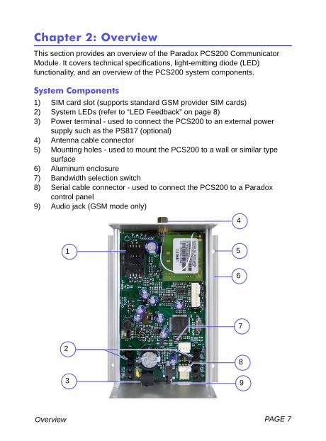
Chapter 2: OverviewThis section provides an overview of the Paradox PCS200 Communicator Module. It covers technical specifications, light-emitting diode (LED) functionality, and an overview of the PCS200 system components.
System Components1) SIM card slot (supports standard GSM provider SIM cards)2) System LEDs (refer to “LED Feedback” on page 8)3) Power terminal - used to connect the PCS200 to an external power
supply such as the PS817 (optional)4) Antenna cable connector5) Mounting holes - used to mount the PCS200 to a wall or similar type
surface6) Aluminum enclosure7) Bandwidth selection switch8) Serial cable connector - used to connect the PCS200 to a Paradox
control panel9) Audio jack (GSM mode only)
2
3 9
8
5
7
1
4
6
PAGE 8 Overview
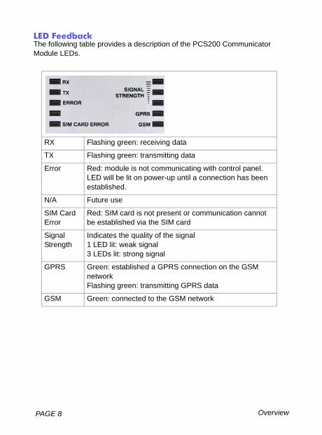
LED FeedbackThe following table provides a description of the PCS200 Communicator Module LEDs.
RX Flashing green: receiving data
TX Flashing green: transmitting data
Error Red: module is not communicating with control panel. LED will be lit on power-up until a connection has been established.
N/A Future use
SIM Card Error
Red: SIM card is not present or communication cannot be established via the SIM card
Signal Strength
Indicates the quality of the signal1 LED lit: weak signal3 LEDs lit: strong signal
GPRS Green: established a GPRS connection on the GSM networkFlashing green: transmitting GPRS data
GSM Green: connected to the GSM network
PAGE 9Overview
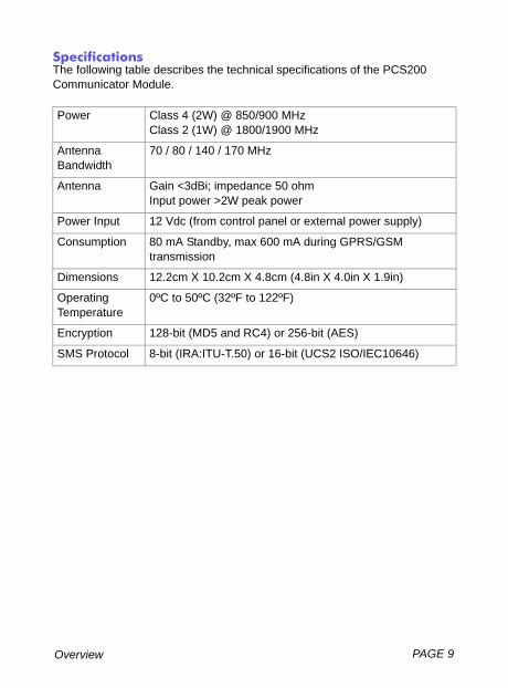
SpecificationsThe following table describes the technical specifications of the PCS200 Communicator Module.
Power Class 4 (2W) @ 850/900 MHzClass 2 (1W) @ 1800/1900 MHz
AntennaBandwidth
70 / 80 / 140 / 170 MHz
Antenna Gain <3dBi; impedance 50 ohmInput power >2W peak power
Power Input 12 Vdc (from control panel or external power supply)
Consumption 80 mA Standby, max 600 mA during GPRS/GSM transmission
Dimensions 12.2cm X 10.2cm X 4.8cm (4.8in X 4.0in X 1.9in)
Operating Temperature
0ºC to 50ºC (32ºF to 122ºF)
Encryption 128-bit (MD5 and RC4) or 256-bit (AES)
SMS Protocol 8-bit (IRA:ITU-T.50) or 16-bit (UCS2 ISO/IEC10646)
PAGE 10 Connections
Chapter 3: ConnectionsThe following sections guide you through the steps required to connect the PCS200 prior to mounting the unit.
SIM Card ConnectionThe PCS200 connects to your Paradox control panel providing wireless communication capabilities to report system events to a monitoring station. The PCS200 supports standard GSM provider SIM cards. The SIM card contains all your cellular telephone account information. In order to activate your SIM card, you must contact your local GSM network provider. Note: Prior to setting up your PCS200, it is important that the Personal Identification Number (PIN) of the SIM card be disabled. Refer to your cellular phone’s manual for more information on how to disable the PIN.
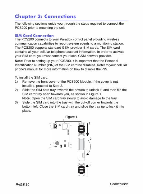
To install the SIM card:1) Remove the front cover of the PCS200 Module. If the cover is not
installed, proceed to Step 2.2) Slide the SIM card tray towards the bottom to unlock it, and then flip the
SIM card tray open towards you, as shown in Figure 1.Note: Open the SIM card tray slowly to avoid damage to the tray.
3) Slide the SIM card into the tray with the cut-off corner towards the bottom left. Close the SIM card tray and slide the tray up to lock it into place.
Figure 1
+ -
1
2
3
PAGE 11Connections
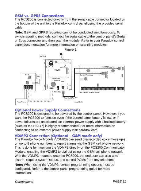
GSM vs. GPRS ConnectionsThe PCS200 is connected directly from the serial cable connector located on the bottom of the unit to the Paradox control panel using the provided serial cable. Note: GSM and GPRS reporting cannot be conducted simultaneously. To switch reporting methods, connect the serial cable to the control panel’s Serial or Ebus connector and then scan the module. Refer to your Paradox control panel documentation for more information on scanning modules.
Figure 2
Optional Power Supply ConnectionsThe PCS200 is designed to be powered by the control panel. However, if you want the PCS200 to function even if the control panel battery is low, or if power failures are anticipated, an external power supply with a backup battery (such as the PS817) is highly recommended. For more information on connecting to an external power supply visit paradox.com.
VDMP3 Connection (Optional - GSM mode only)The Paradox Voice Module (VDMP3) can send pre-recorded voice messages on up to 8 phone numbers to report alarms via the GSM cell phone network. This is done by mounting the VDMP3 directly on the PCS200 Communicator Module, enabling the VDMP3 to dial out using the GSM cell phone network. With the VDMP3 mounted onto the PCS200, the end user can also arm/disarm, request system status, and control PGMs from any telephone. Note: When using the VDMP3, certain programming options must be configured. Refer to the control panel programming guide for more information.
AC AC + - TST
DIAL
ER E
BUS
for GPRS Reporting
for GSM Reporting
SERI
AL
Paradox Control PanelPCS200
PS-817
SIM Card
Transformer
Batt.
Up to 2m ( 6ft.)
SERIAL (UART) +
Serial Cable
Connector
-
VDMP3DI
ALER
EBUS
Serial Cable
PAGE 12 Installation
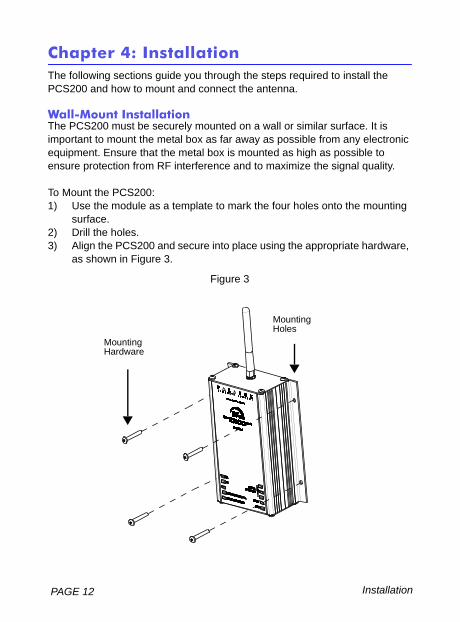
Chapter 4: InstallationThe following sections guide you through the steps required to install the PCS200 and how to mount and connect the antenna.
Wall-Mount InstallationThe PCS200 must be securely mounted on a wall or similar surface. It is important to mount the metal box as far away as possible from any electronic equipment. Ensure that the metal box is mounted as high as possible to ensure protection from RF interference and to maximize the signal quality.
To Mount the PCS200:1) Use the module as a template to mark the four holes onto the mounting
surface. 2) Drill the holes.3) Align the PCS200 and secure into place using the appropriate hardware,
as shown in Figure 3.
Figure 3
MountingHoles
MountingHardware
PAGE 13Installation
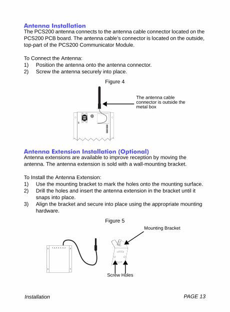
Antenna InstallationThe PCS200 antenna connects to the antenna cable connector located on the PCS200 PCB board. The antenna cable’s connector is located on the outside, top-part of the PCS200 Communicator Module.
To Connect the Antenna:1) Position the antenna onto the antenna connector. 2) Screw the antenna securely into place.
Figure 4
Antenna Extension Installation (Optional)Antenna extensions are available to improve reception by moving the antenna. The antenna extension is sold with a wall-mounting bracket.
To Install the Antenna Extension:1) Use the mounting bracket to mark the holes onto the mounting surface. 2) Drill the holes and insert the antenna extension in the bracket until it
snaps into place. 3) Align the bracket and secure into place using the appropriate mounting
hardware.
Figure 5
The antenna cable connector is outside the metal box
Mounting Bracket
Screw Holes
PAGE 14 Configuring the PCS200
Chapter 5: Configuring the PCS200The PCS200 can be configured for GSM or GPRS reporting. In order for the unit to provide GSM or GPRS reporting, certain configurations must be set. These configurations include modifying the frequency band, configuring GSM network provider information, configuring the PCS200 for WinLoad access, programming GSM reporting options, and registering and programming GPRS reporting options.
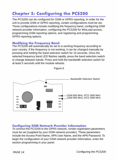
Modifying the Frequency BandThe PCS200 will automatically be set to a working frequency according to your country. If the frequency is not working, it can be changed manually by pressing and holding the band selection switch for 10 seconds. Once the selected frequency band LED flashes rapidly, press the band selection switch to change between bands. Press and hold the bandwidth selection switch for at least 5 seconds until the module reboots.
Figure 6
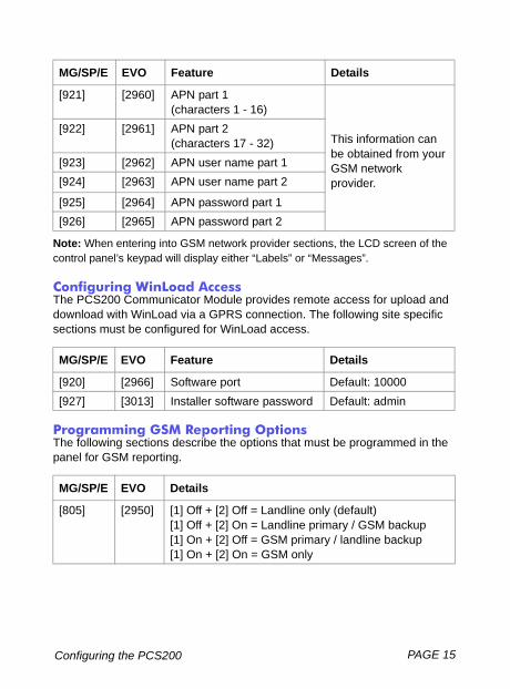
Configuring GSM Network Provider InformationTo connect the PCS200 to the GPRS network, certain registration parameters must be set (supplied by your GSM network provider). These parameters include the Access Point Name, APN User Name, and the APN Password. To begin the configuration of your GSM network provider information, enter the section programming in your panel.
+ -
Bandwidth Selection Switch
GSM 850 MHz, PCS 1900 MHzGSM 900 MHz, DCS 1800 MHz
PAGE 15Configuring the PCS200
Note: When entering into GSM network provider sections, the LCD screen of the control panel’s keypad will display either “Labels” or “Messages”.
Configuring WinLoad AccessThe PCS200 Communicator Module provides remote access for upload and download with WinLoad via a GPRS connection. The following site specific sections must be configured for WinLoad access.
Programming GSM Reporting OptionsThe following sections describe the options that must be programmed in the panel for GSM reporting.
MG/SP/E EVO Feature Details
[921] [2960] APN part 1 (characters 1 - 16)
This information can be obtained from your GSM network provider.
[922] [2961] APN part 2 (characters 17 - 32)
[923] [2962] APN user name part 1[924] [2963] APN user name part 2
[925] [2964] APN password part 1[926] [2965] APN password part 2
MG/SP/E EVO Feature Details
[920] [2966] Software port Default: 10000[927] [3013] Installer software password Default: admin
MG/SP/E EVO Details
[805] [2950] [1] Off + [2] Off = Landline only (default)[1] Off + [2] On = Landline primary / GSM backup[1] On + [2] Off = GSM primary / landline backup[1] On + [2] On = GSM only
PAGE 16 Configuring the PCS200
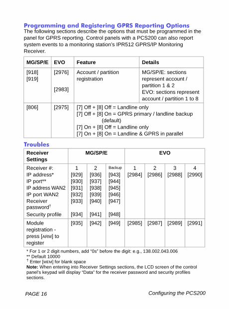
Programming and Registering GPRS Reporting OptionsThe following sections describe the options that must be programmed in the panel for GPRS reporting. Control panels with a PCS200 can also report system events to a monitoring station’s IPR512 GPRS/IP Monitoring Receiver.
Troubles
MG/SP/E EVO Feature Details
[918][919]
[2976] Account / partition registration
MG/SP/E: sections represent account / partition 1 & 2EVO: sections represent account / partition 1 to 8
[2983]
[806] [2975] [7] Off + [8] Off = Landline only [7] Off + [8] On = GPRS primary / landline backup
(default)[7] On + [8] Off = Landline only[7] On + [8] On = Landline & GPRS in parallel
Receiver Settings
MG/SP/E EVO
Receiver #:IP address*IP port**IP address WAN2IP port WAN2Receiver password†
Security profile
1[929][930][931][932][933]
[934]
2[936][937][938][939][940]
[941]
Backup
[943][944][945][946][947]
[948]
1[2984]
2[2986]
3[2988]
4[2990]
Module registration -press [ARM] to register
[935] [942] [949] [2985] [2987] [2989] [2991]
* For 1 or 2 digit numbers, add “0s” before the digit: e.g., 138.002.043.006** Default 10000† Enter [MEM] for blank spaceNote: When entering into Receiver Settings sections, the LCD screen of the control panel’s keypad will display “Data” for the receiver password and security profiles sections.
PAGE 17Configuring the PCS200
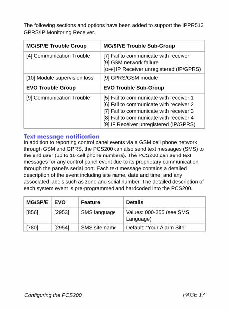
The following sections and options have been added to support the IPPR512 GPRS/IP Monitoring Receiver.
Text message notificationIn addition to reporting control panel events via a GSM cell phone network through GSM and GPRS, the PCS200 can also send text messages (SMS) to the end user (up to 16 cell phone numbers). The PCS200 can send text messages for any control panel event due to its proprietary communication through the panel’s serial port. Each text message contains a detailed description of the event including site name, date and time, and any associated labels such as zone and serial number. The detailed description of each system event is pre-programmed and hardcoded into the PCS200.
MG/SP/E Trouble Group MG/SP/E Trouble Sub-Group
[4] Communication Trouble [7] Fail to communicate with receiver[9] GSM network failure[OFF] IP Receiver unregistered (IP/GPRS)
[10] Module supervision loss [9] GPRS/GSM module
EVO Trouble Group EVO Trouble Sub-Group
[9] Communication Trouble [5] Fail to communicate with receiver 1[6] Fail to communicate with receiver 2[7] Fail to communicate with receiver 3[8] Fail to communicate with receiver 4[9] IP Receiver unregistered (IP/GPRS)
MG/SP/E EVO Feature Details
[856] [2953] SMS language Values: 000-255 (see SMS Language)
[780] [2954] SMS site name Default: “Your Alarm Site”
PAGE 18 Configuring the PCS200
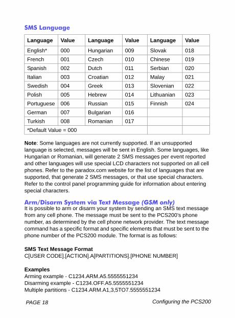
SMS Language
Note: Some languages are not currently supported. If an unsupported language is selected, messages will be sent in English. Some languages, like Hungarian or Romanian, will generate 2 SMS messages per event reported and other languages will use special LCD characters not supported on all cell phones. Refer to the paradox.com website for the list of languages that are supported, that generate 2 SMS messages, or that use special characters. Refer to the control panel programming guide for information about entering special characters.
Arm/Disarm System via Text Message (GSM only)It is possible to arm or disarm your system by sending an SMS text message from any cell phone. The message must be sent to the PCS200’s phone number, as determined by the cell phone network provider. The text message command has a specific format and specific elements that must be sent to the phone number of the PCS200 module. The format is as follows:
SMS Text Message FormatC[USER CODE].[ACTION].A[PARTITIONS].[PHONE NUMBER]
ExamplesArming example - C1234.ARM.A5.5555551234 Disarming example - C1234.OFF.A5.5555551234 Multiple partitions - C1234.ARM.A1,3,5TO7.5555551234
Language Value Language Value Language Value
English* 000 Hungarian 009 Slovak 018French 001 Czech 010 Chinese 019Spanish 002 Dutch 011 Serbian 020Italian 003 Croatian 012 Malay 021Swedish 004 Greek 013 Slovenian 022Polish 005 Hebrew 014 Lithuanian 023Portuguese 006 Russian 015 Finnish 024German 007 Bulgarian 016Turkish 008 Romanian 017*Default Value = 000
PAGE 19Upload/Download
Chapter 6: Upload/DownloadFast upload/download can be configured via WinLoad or NEware using a GPRS connection. Upload and download can be achieved on both public and private networks. To find out the type of provider network you are currently set up on, contact your local SIM card provider for more information.
Public Network (GPRS mode only)In order to connect to the GPRS network, you must verify the connection by receiving the IP address of the PCS200 Communicator Module. Before beginning any upload/download procedures you must ensure that the registration parameters of the PCS200 have been set. Note: It is important that the router used with the PCS200 application (WinLoad and NEware) has been set up for port forwarding to ensure proper system functionality.
To receive the IP address of the PCS200 via text message you must use a cellular phone and enter:
P[TCP/IP passwrd].IP.[phone number to answer back] i.e. Padmin.IP.5551231234
The PCS200 will send a response to the specified phone number displaying the IP address of the module. This information must be entered into the WinLoad application. The IP address can then be used to configure remote software access.
Private NetworkIf your SIM card provider is on a private network, communication to the PCS200 must first be established via an SMS message. When the SMS message is sent to the PCS200, the PCS200 will then initiate a connection with WinLoad. Once communication is established, firmware upgrades, as well as upload and download configurations and system programming can begin. Before beginning any upload/download procedures you must ensure that the registration parameters of the PCS200 have been set. Note: It is important that the router used with the PCS200 application (WinLoad and NEware) has been set up for port forwarding to ensure proper PCS200 system functionality.
PAGE 20 Upload/Download
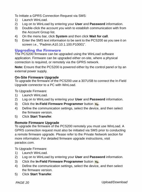
To Initiate a GPRS Connection Request via SMS:1) Launch WinLoad.2) Log on to WinLoad by entering your User and Password information.3) Double-click the account you wish to establish communication with from
the Account Group list.4) On the menu bar, click System and then click Wait for call.5) Enter the SMS text information to be sent to the PCS200 as you see it on
screen i.e., “Padmin.A10.10.1.100.P10001”.
Upgrading the FirmwareThe PCS200 firmware can be upgraded using the WinLoad software application. Firmware can be upgraded either on-site, where a physical connection is required, or remotely via the GPRS network. Note: Ensure that the PCS200 is powered either by the control panel or by an external power supply.
On-Site Firmware UpgradeTo upgrade the firmware of the PCS200 use a 307USB to connect the In-Field Upgrade connector to a PC with WinLoad.
To Upgrade Firmware:1) Launch WinLoad.2) Log on to WinLoad by entering your User and Password information.3) Click the In-Field Firmware Programmer button . 4) Define the communication settings, select the device, and then select
the firmware version. 5) Click Start Transfer.
Remote Firmware UpgradeTo upgrade the firmware of the PCS200 remotely you must use WinLoad. A GPRS connection request must also be initiated via SMS prior to conducting a remote firmware upgrade. Please refer to the Private Network section for more information. For detailed firmware upgrade instructions, visit paradox.com.
To Upgrade Firmware:1) Launch WinLoad.2) Log on to WinLoad by entering your User and Password information.3) Click the In-Field Firmware Programmer button . 4) Define the communication settings, select the device, and then select
the firmware version. 5) Click Start Transfer.
PAGE 21Module Supervision Options
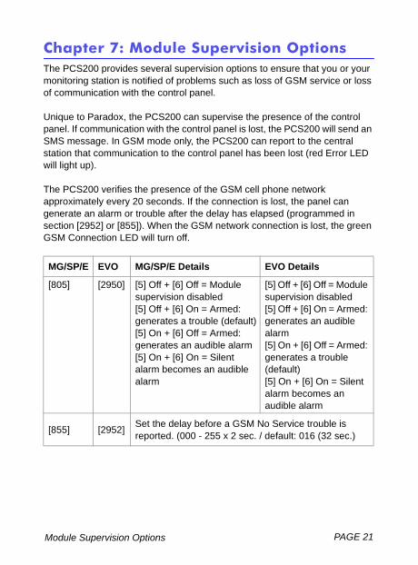
Chapter 7: Module Supervision OptionsThe PCS200 provides several supervision options to ensure that you or your monitoring station is notified of problems such as loss of GSM service or loss of communication with the control panel.
Unique to Paradox, the PCS200 can supervise the presence of the control panel. If communication with the control panel is lost, the PCS200 will send an SMS message. In GSM mode only, the PCS200 can report to the central station that communication to the control panel has been lost (red Error LED will light up).
The PCS200 verifies the presence of the GSM cell phone network approximately every 20 seconds. If the connection is lost, the panel can generate an alarm or trouble after the delay has elapsed (programmed in section [2952] or [855]). When the GSM network connection is lost, the green GSM Connection LED will turn off.
MG/SP/E EVO MG/SP/E Details EVO Details
[805] [2950] [5] Off + [6] Off = Module supervision disabled[5] Off + [6] On = Armed: generates a trouble (default)[5] On + [6] Off = Armed: generates an audible alarm[5] On + [6] On = Silent alarm becomes an audible alarm
[5] Off + [6] Off = Module supervision disabled[5] Off + [6] On = Armed: generates an audible alarm[5] On + [6] Off = Armed: generates a trouble (default)[5] On + [6] On = Silent alarm becomes an audible alarm
[855] [2952] Set the delay before a GSM No Service trouble is reported. (000 - 255 x 2 sec. / default: 016 (32 sec.)
PAGE 22 Module Supervision Options
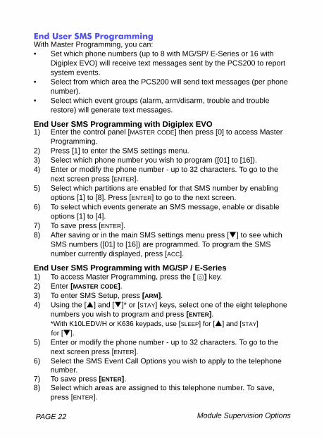
End User SMS ProgrammingWith Master Programming, you can:• Set which phone numbers (up to 8 with MG/SP/ E-Series or 16 with
Digiplex EVO) will receive text messages sent by the PCS200 to report system events.
• Select from which area the PCS200 will send text messages (per phone number).
• Select which event groups (alarm, arm/disarm, trouble and trouble restore) will generate text messages.
End User SMS Programming with Digiplex EVO1) Enter the control panel [MASTER CODE] then press [0] to access Master
Programming.2) Press [1] to enter the SMS settings menu.3) Select which phone number you wish to program ([01] to [16]). 4) Enter or modify the phone number - up to 32 characters. To go to the
next screen press [ENTER].5) Select which partitions are enabled for that SMS number by enabling
options [1] to [8]. Press [ENTER] to go to the next screen.6) To select which events generate an SMS message, enable or disable
options [1] to [4].7) To save press [ENTER]. 8) After saving or in the main SMS settings menu press [ ] to see which
SMS numbers ([01] to [16]) are programmed. To program the SMS number currently displayed, press [ACC].
End User SMS Programming with MG/SP / E-Series1) To access Master Programming, press the [ ] key.2) Enter [MASTER CODE].3) To enter SMS Setup, press [ARM]. 4) Using the [ ] and [ ]* or [STAY] keys, select one of the eight telephone
numbers you wish to program and press [ENTER].*With K10LEDV/H or K636 keypads, use [SLEEP] for [ ] and [STAY] for [ ].
5) Enter or modify the phone number - up to 32 characters. To go to the next screen press [ENTER].
6) Select the SMS Event Call Options you wish to apply to the telephone number.
7) To save press [ENTER].8) Select which areas are assigned to this telephone number. To save,
press [ENTER].
PAGE 23Module Supervision Options
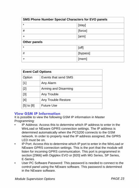
View GSM IP InformationIt is possible to view the following GSM IP information in Master Programming:• IP Address: Access this to determine which IP address to enter in the
WinLoad or NEware GPRS connection settings. The IP address is determined automatically when the PCS200 connects to the GSM network. In order to properly read the IP address assigned, the GPRS LED must be on.
• IP Port: Access this to determine which IP port to enter in the WinLoad or NEware GPRS connection settings. This is the port that the module will listen for incoming GPRS communication. This port is programmed in section [2966] with Digiplex EVO or [920] with MG Series, SP Series, E-Series.
• User PC Software Password: This password is needed to connect to the control panel using the NEware software. This password is determined in the NEware software.
SMS Phone Number Special Characters for EVO panels
* [stay]
# [force]
+ [arm]
Other panels
* [off]
# [bypass]
+ [mem]
Event Call Options
Option Events that send SMS
[1] Any Alarm
[2] Arming and Disarming
[3] Any Trouble
[4] Any Trouble Restore
[5] to [8] Future Use
PAGE 24 Module Supervision Options
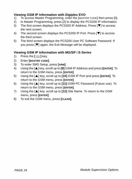
Viewing GSM IP Information with Digiplex EVO1) To access Master Programming, enter the [MASTER CODE] then press [0].2) In Master Programming, press [2] to display the PCS200 IP information.3) The first screen displays the PCS200 IP Address. Press [ ] to access
the next screen. 4) The second screen displays the PCS200 IP Port. Press [ ] to access
the third screen. 5) The third screen displays the PCS200 User PC Software Password. If
you press [ ] again, the Exit Message will be displayed.
Viewing GSM IP Information with MG/SP / E-Series1) Press the [ ] key.2) Enter [MASTER CODE].3) To enter SMS Setup, press [ARM].4) Using the [ ] key, scroll up to [9] GSM IP Address and press [ENTER]. To
return to the GSM menu, press [ENTER].5) Using the [ ] key, scroll up to [10] GSM IP Port and press [ENTER]. To
return to the GSM menu, press [ENTER].6) Using the [ ] key, scroll up to [11] GSM PC Password (Future use). To
return to the GSM menu, press [ENTER].7) Using the [ ] key, scroll up to [12] Site Name. To return to the GSM
menu, press [ENTER].8) To exit the GSM menu, press [CLEAR].
PAGE 25Pre-Defined Text Messages
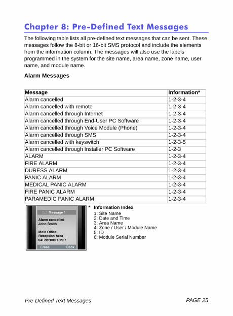
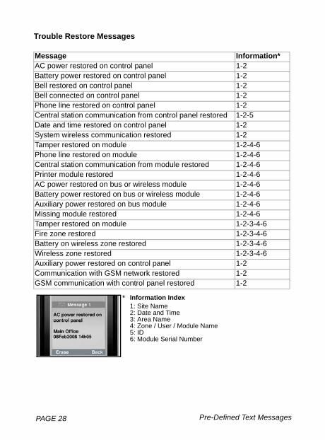
Chapter 8: Pre-Defined Text MessagesThe following table lists all pre-defined text messages that can be sent. These messages follow the 8-bit or 16-bit SMS protocol and include the elements from the information column. The messages will also use the labels programmed in the system for the site name, area name, zone name, user name, and module name.
Alarm Messages
Message Information*Alarm cancelled 1-2-3-4Alarm cancelled with remote 1-2-3-4Alarm cancelled through Internet 1-2-3-4Alarm cancelled through End-User PC Software 1-2-3-4Alarm cancelled through Voice Module (Phone) 1-2-3-4Alarm cancelled through SMS 1-2-3-4Alarm cancelled with keyswitch 1-2-3-5Alarm cancelled through Installer PC Software 1-2-3ALARM 1-2-3-4FIRE ALARM 1-2-3-4DURESS ALARM 1-2-3-4PANIC ALARM 1-2-3-4MEDICAL PANIC ALARM 1-2-3-4FIRE PANIC ALARM 1-2-3-4PARAMEDIC PANIC ALARM 1-2-3-4
Information Index1: Site Name2: Date and Time3: Area Name4: Zone / User / Module Name5: ID6: Module Serial Number
*
PAGE 26 Pre-Defined Text Messages
Arming/Disarming Messages
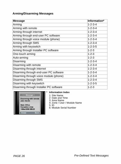
Message Information*Arming 1-2-3-4Arming with remote 1-2-3-4Arming through internet 1-2-3-4Arming through end-user PC software 1-2-3-4Arming through voice module (phone) 1-2-3-4Arming through SMS 1-2-3-4Arming with keyswitch 1-2-3-5Arming through Installer PC software 1-2-3One-touch arming 1-2-3Auto-arming 1-2-3Disarming 1-2-3-4Disarming with remote 1-2-3-4Disarming through internet 1-2-3-4Disarming through end-user PC software 1-2-3-4Disarming through voice module (phone) 1-2-3-4Disarming through SMS 1-2-3-4Disarming with keyswitch 1-2-3-5Disarming through Installer PC software 1-2-3
Information Index1: Site Name2: Date and Time3: Area Name4: Zone / User / Module Name5: ID6: Module Serial Number
*
PAGE 27Pre-Defined Text Messages
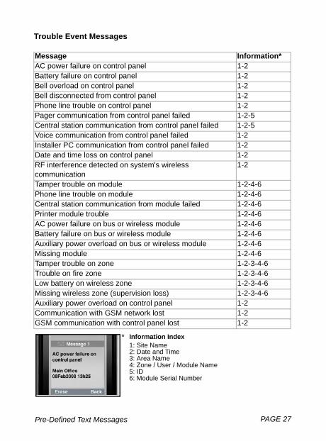
Trouble Event Messages
Message Information*AC power failure on control panel 1-2Battery failure on control panel 1-2Bell overload on control panel 1-2Bell disconnected from control panel 1-2Phone line trouble on control panel 1-2Pager communication from control panel failed 1-2-5Central station communication from control panel failed 1-2-5Voice communication from control panel failed 1-2Installer PC communication from control panel failed 1-2Date and time loss on control panel 1-2RF interference detected on system's wireless communication
1-2
Tamper trouble on module 1-2-4-6Phone line trouble on module 1-2-4-6Central station communication from module failed 1-2-4-6Printer module trouble 1-2-4-6AC power failure on bus or wireless module 1-2-4-6Battery failure on bus or wireless module 1-2-4-6Auxiliary power overload on bus or wireless module 1-2-4-6Missing module 1-2-4-6Tamper trouble on zone 1-2-3-4-6Trouble on fire zone 1-2-3-4-6Low battery on wireless zone 1-2-3-4-6Missing wireless zone (supervision loss) 1-2-3-4-6Auxiliary power overload on control panel 1-2Communication with GSM network lost 1-2GSM communication with control panel lost 1-2
Information Index1: Site Name2: Date and Time3: Area Name4: Zone / User / Module Name5: ID6: Module Serial Number
*
PAGE 28 Pre-Defined Text Messages
Trouble Restore Messages
Message Information*AC power restored on control panel 1-2Battery power restored on control panel 1-2Bell restored on control panel 1-2Bell connected on control panel 1-2Phone line restored on control panel 1-2Central station communication from control panel restored 1-2-5Date and time restored on control panel 1-2System wireless communication restored 1-2Tamper restored on module 1-2-4-6Phone line restored on module 1-2-4-6Central station communication from module restored 1-2-4-6Printer module restored 1-2-4-6AC power restored on bus or wireless module 1-2-4-6Battery power restored on bus or wireless module 1-2-4-6Auxiliary power restored on bus module 1-2-4-6Missing module restored 1-2-4-6Tamper restored on module 1-2-3-4-6Fire zone restored 1-2-3-4-6Battery on wireless zone restored 1-2-3-4-6Wireless zone restored 1-2-3-4-6Auxiliary power restored on control panel 1-2Communication with GSM network restored 1-2GSM communication with control panel restored 1-2
Information Index1: Site Name2: Date and Time3: Area Name4: Zone / User / Module Name5: ID6: Module Serial Number
*
Index PAGE 29
IndexAAccess Point Name................... 14Alarm Messages........................ 25Antenna ................................. 9, 13Antenna Bandwidth ..................... 9antenna cable connector ........... 13Antenna extension ..................... 13Antenna Installation ................... 13Antenna installation ................... 13APN Password .......................... 14APN User Name ........................ 14Arm/Disarm ............................... 18Arming/Disarming Messages .... 26Audio jack .................................... 7
CCancel SMS .............................. 24Compatibility ................................ 6Configuring the PCS200 ............ 14Consumption ............................... 9
DDigiPlex EVO ............................. 22Digiplex EVO ............................. 24Dimensions .................................. 9
EE55 .............................................. 6E65 .............................................. 6Encryption ................................... 9End user SMS programming ..... 22Error ............................................ 8Error LED .................................. 21Event Call Options ..................... 23EVO192 ....................................... 6EVO48 ......................................... 6
FFeatures ....................................... 5
GGPRS ........................................... 8GPRS network ........................... 14GPRS reporting ......................... 16GSM ............................................. 8GSM cell phone network ............ 21GSM Connection LED ............... 21GSM reporting ........................... 15GSM reporting options ............... 14GSM vs. GPRS Connections ..... 11
IIncluded Items ............................. 6Installation .................................. 12IP Address ................................. 23IP Port ........................................ 23IPR512 GPRS/IP Monitoring Receiver ..................................... 16
KK641 ............................................ 6K641R .......................................... 6
LLED ........................................ 7, 14LED Feedback ............................. 8light-emitting diodes ..................... 7Loss of GSM service .................. 21
MMaster Programming ................. 22MG series .................................... 6MG/SP / E-Series ................ 22, 24
PAGE 30 Index
NNEware ...................................... 19
OOn-Site Firmware Upgrade ....... 20Operating Temperature ............... 9
PPower input ................................. 9Power Supply ............................ 11Power Supply connections ........ 11Pre-defined text messages ........ 25Private Network ......................... 19Public Network .......................... 19
RRegistering and programming GPRS reporting options ............ 14Registration parameters ............ 14Remote Firmware Upgrade ....... 20Required/Optional Items .............. 6RX ............................................... 8
SSerial cable ................................ 11Serial cable connector ............... 11Signal Strength ............................ 8SIM Card Connection ................ 10SIM Card Error ............................ 8SMS message ........................... 21SMS Phone Number Special Characters................................. 23SMS Protocol .............................. 9SMS text message format ......... 18SP series ..................................... 6Specifications .............................. 9System Components ................... 7System features .......................... 5
TTechnical specifications ............... 9Text message notification .......... 17Trouble Event Messages ........... 27Trouble Restore Messages ........ 28Troubles ..................................... 16TX ................................................ 8
UUpgrading the Firmware ............ 20Upload/download ....................... 19User PC Software Password ..... 23
VVDMP3 ...................................... 11VDMP3 Connection ................... 11View GSM IP Information .......... 23
WWait for call ................................ 20Wall-Mount Installation .............. 12WinLoad ..................................... 19WinLoad access .................. 14, 15


PCS200-EI06 08/2009 Printed in CanadaPARADOX.COM
For technical support in Canada or the U.S., call 1-800-791-1919, Monday to Friday from 8:00 a.m. to 8:00 p.m. EST. For technical support outside Canada and the U.S., call 00-1-450-491-7444,
Monday to Friday from 8:00 a.m. to 8:00 p.m. EST.Please feel free to visit our website at www.paradox.com.