Embed Size (px)
Citation preview
Installation Manual IM 997
Pathfinder™ Air Cooled Chillers Group: Chillers
Part Number: 10000199901
Date: June 1, 2009
© 2009 McQuay International
Models AWS 300ADS to AWS 350ADS (Standard Efficiency)
Models AWS 350ADH to AWS 405ADH (High Efficiency) 300 to 405 Tons, 1053 to 1420 kW
R-134a
60 Hz
Contents
Introduction . . . . . . . . . . . . . . . . . . . . . . . . . . . . . . . 3Installation and Startup . . . . . . . . . . . . . . . . . . . . . 4
Handling . . . . . . . . . . . . . . . . . . . . . . . . . . . . . 4Location. . . . . . . . . . . . . . . . . . . . . . . . . . . . . . 4Service Access . . . . . . . . . . . . . . . . . . . . . . . . 4Clearance Requirements . . . . . . . . . . . . . . . . 5Restricted Air Flow . . . . . . . . . . . . . . . . . . . . . 6Chilled Water. . . . . . . . . . . . . . . . . . . . . . . . . . 9Water Piping . . . . . . . . . . . . . . . . . . . . . . . . . . 9System Water Volume . . . . . . . . . . . . . . . . . . 9Variable Speed Pumping . . . . . . . . . . . . . . . . 9Evaporator Freeze Protection . . . . . . . . . . . . 10Flow Switch . . . . . . . . . . . . . . . . . . . . . . . . . . 10
Performance Adjustment Factors . . . . . . . . . . 11Physical Data. . . . . . . . . . . . . . . . . . . . . . . . . . . . . 13 . . . . . . . . . . . . . . . . . . . . . . . . . . . . . . . . . . . . . . . . 13 . . . . . . . . . . . . . . . . . . . . . . . . . . . . . . . . . . . . . . . . 14 . . . . . . . . . . . . . . . . . . . . . . . . . . . . . . . . . . . . . . . . 14Dimensions . . . . . . . . . . . . . . . . . . . . . . . . . . . . . . 15Lifting & Mounting Weights . . . . . . . . . . . . . . . . . 21Lifting and Mounting Locations . . . . . . . . . . . . . 22Isolator Locations and Kit Numbers . . . . . . . . . . 25Electrical Data . . . . . . . . . . . . . . . . . . . . . . . . . . . . 28Wiring Diagram . . . . . . . . . . . . . . . . . . . . . . . . . . . 32Troubleshooting Chart . . . . . . . . . . . . . . . . . . . . . 35
Hazard Identification
©2009 McQuay International. Illustrations and data cover the McQuay International product at the time of publication and we reserve the right to make changes in design and construction at anytime without notice. ™® The following are trademarks or registered trademarks of their respective companies: BACnet from ASHRAE; LONMARK, LonTalk, LONWORKS, and the LONMARK logo are managed, granted and used by LONMARK International under a license granted by Echelon Corporation; ElectroFin from AST ElectroFin Inc.; Modbus from Schneider Electric; FanTrol, MicroTech III, Open Choices, and SpeedTrol from McQuay International
DANGER
Dangers indicate a hazardous situation which will result in death or serious injury if not avoided.
WARNING
Warnings indicate potentially hazardous situations, which can result in property damage, severe personal injury, or death if not avoided.
CAUTION
Cautions indicate potentially hazardous situations, which can result in personal injury or equipment damage if not avoided.
Document: IM 997 Issue Date: June 2009Revision Date: June 11, 2009Replaces: June 1, 2009
Modbus
Introduction
IntroductionFigure 1: Model Nomenclature
General Description
Daikin McQuay Pathfinder™ air-cooled chillers are complete, self-contained chillers that include the latest in engineered components arranged to provide a compact and efficient unit. Each unit is completely assembled, factory wired, evacuated, charged, tested and comes complete and ready for installation. Each of two circuits consists of an air-cooled condenser section with an integral subcooler section, a semi-hermetic, single-screw compressor with starter, a multi-circuit, shell-and-tube, direct expansion evaporator, an economizer and complete refrigerant piping. Each compressor has an independent refrigeration circuit. Liquid line components included are a manual liquid line shutoff valve, charging port, filter-drier, sight-glass/moisture indicator, and electronic expansion valve. A combination discharge check and shutoff valve is included and a compressor suction shutoff valve is optional. Other features include compressor heaters, evaporator heaters for freeze protection, automatic, one-time pumpdown of each refrigerant circuit upon circuit shutdown, and an advanced fully integrated microprocessor control system.
Pathfinder units are available as standard efficiency (ADS) or high efficiency (ADH)
A high ambient option is required for operation in ambient temperatures above 105F (40.6C) and up to 125F (51.7C) and when the VFD low ambient option is selected.
Information on the operation of the unit MicroTechIII controller is in the OM 998 manual.
Inspection
When the equipment is received, carefully check all items against the bill of lading to verify for a complete shipment. Check all units for damage upon arrival. All shipping damage must be reported to the carrier and a claim must be filed with the carrier. Check the unit’s serial plate before unloading the unit to be sure that it agrees with the power supply available. Physical damage to a unit after shipment is not McQuay International’s responsibility.
Note: Unit shipping and operating weights are shown in the Physical Data Tables beginning on page 13.
S = Standard EfficiencyH = High Efficiency
A W S XXX A D S
Air-Cooled
World ProductScrew Compressor
Nominal Tons
Dual CompressorDesign Vintage
Table 1: Operating Limits
Maximum standby ambient temperature 130°F (55°C)
Maximum operating ambient temperature 105°F (40.6°C)
with optional high ambient package (see detailed information on page 3 125°F (52°C)
Minimum operating ambient temperature (standard control) 35°F (2°C)
Minimum operating ambient temperature (with optional low-ambient control) 0°F (-18°C)
Leaving chilled water temperature 40°F to 60°F (4.4°C to 15.6°C)
Leaving chilled fluid temperatures (with anti-freeze) - Unloading is not permitted with fluid leaving temperatures below 30°F (-1°C). 20°F to 60°F (-7°C to 16°C)
Operating chilled water delta-T range 6 to 18°F (-14 to -8°C)
Maximum evaporator operating inlet fluid temperature 76°F (24°C)
Maximum evaporator non-operating inlet fluid temperature 100°F (38°C)
IM 997 3
Installation and Startup
Installation and StartupInstallation and maintenance are to be performed only by qualified personnel who are familiar with local codes and regulations, and experienced with this type of equipment.
Start-up by McQuay Factory Service is included on all Pathfinder units sold for installation within the U.S. and Canada and must be performed by them to initiate the standard Limited Product Warranty. Start-up by any party other than McQuay Factory Service or a McQuay Authorized Service Representative will void the Limited Product Warranty. Two-week prior notification of start-up is required. The contractor should obtain a copy of the Start-up Scheduled Request Form from the sales representative or from the nearest McQuay Factory Service office.
Handling
Avoid rough handling shock due to impact or dropping the unit. Do not push or pull the unit. Never allow any part of the unit to fall during unloading or moving, as this can result in serious damage.
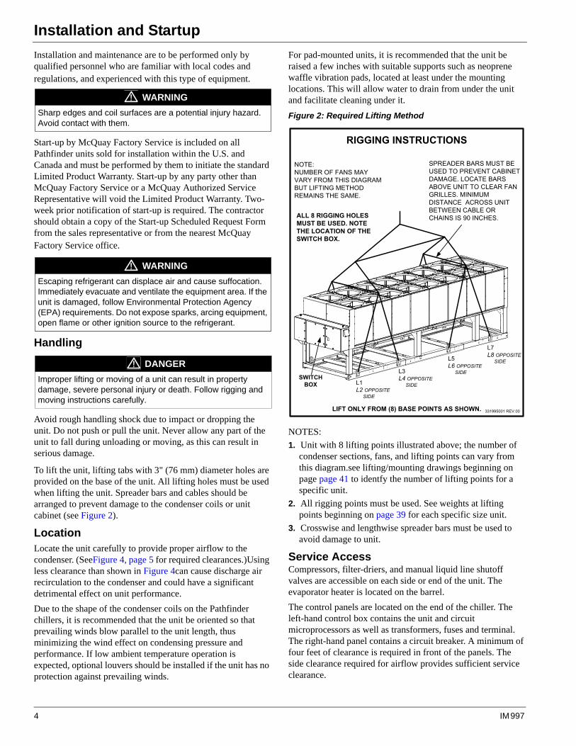
To lift the unit, lifting tabs with 3" (76 mm) diameter holes are provided on the base of the unit. All lifting holes must be used when lifting the unit. Spreader bars and cables should be arranged to prevent damage to the condenser coils or unit cabinet (see Figure 2).
LocationLocate the unit carefully to provide proper airflow to the condenser. (SeeFigure 4, page 5 for required clearances.)Using less clearance than shown in Figure 4can cause discharge air recirculation to the condenser and could have a significant detrimental effect on unit performance.
Due to the shape of the condenser coils on the Pathfinder chillers, it is recommended that the unit be oriented so that prevailing winds blow parallel to the unit length, thus minimizing the wind effect on condensing pressure and performance. If low ambient temperature operation is expected, optional louvers should be installed if the unit has no protection against prevailing winds.
For pad-mounted units, it is recommended that the unit be raised a few inches with suitable supports such as neoprene waffle vibration pads, located at least under the mounting locations. This will allow water to drain from under the unit and facilitate cleaning under it.
Figure 2: Required Lifting Method
NOTES:
1. Unit with 8 lifting points illustrated above; the number of condenser sections, fans, and lifting points can vary from this diagram.see lifting/mounting drawings beginning on page page 41 to identfy the number of lifting points for a specific unit.
2. All rigging points must be used. See weights at lifting points beginning on page 39 for each specific size unit.
3. Crosswise and lengthwise spreader bars must be used to avoid damage to unit.
Service AccessCompressors, filter-driers, and manual liquid line shutoff valves are accessible on each side or end of the unit. The evaporator heater is located on the barrel.
The control panels are located on the end of the chiller. The left-hand control box contains the unit and circuit microprocessors as well as transformers, fuses and terminal. The right-hand panel contains a circuit breaker. A minimum of four feet of clearance is required in front of the panels. The side clearance required for airflow provides sufficient service clearance.
WARNING
Sharp edges and coil surfaces are a potential injury hazard. Avoid contact with them.
WARNING
Escaping refrigerant can displace air and cause suffocation. Immediately evacuate and ventilate the equipment area. If the unit is damaged, follow Environmental Protection Agency (EPA) requirements. Do not expose sparks, arcing equipment, open flame or other ignition source to the refrigerant.
DANGER
Improper lifting or moving of a unit can result in property damage, severe personal injury or death. Follow rigging and moving instructions carefully.
������������������
�������������� ���� ��� ������������� � ���������������������� ��������� ���
���������������
� ������������� ������������������������ ������������������������
���������
��� ��� ������������������������� ������ � ������� ��� �� ��������������� �� ���������������������� ����� ������������������ ������� �����������������
������ ��������������������������������
�������������������
�������������������
��� ���������������
��������������������
4 IM 997
Installation and Startup
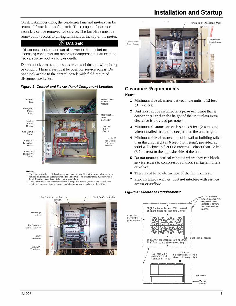
On all Pathfinder units, the condenser fans and motors can be removed from the top of the unit. The complete fan/motor assembly can be removed for service. The fan blade must be removed for access to wiring terminals at the top of the motor.
Do not block access to the sides or ends of the unit with piping or conduit. These areas must be open for service access. Do not block access to the control panels with field-mounted disconnect switches.
Figure 3: Control and Power Panel Component Location Clearance RequirementsNotes:
1 Minimum side clearance between two units is 12 feet (3.7 meters).
2 Unit must not be installed in a pit or enclosure that is deeper or taller than the height of the unit unless extra clearance is provided per note 4.
3 Minimum clearance on each side is 8 feet (2.4 meters) when installed in a pit no deeper than the unit height.
4 Minimum side clearance to a side wall or building taller than the unit height is 6 feet (1.8 meters), provided no solid wall above 6 feet (1.8 meters) is closer than 12 feet (3.7 meters) to the opposite side of the unit.
5 Do not mount electrical conduits where they can block service access to compressor controls, refrigerant driers or valves.
6 There must be no obstruction of the fan discharge.
7 Field installed switches must not interfere with service access or airflow.
Figure 4: Clearance Requirements
DANGER
Disconnect, lockout and tag all power to the unit before servicing condenser fan motors or compressors. Failure to do so can cause bodily injury or death.
Fan Contactors, 1 per Fan Circuit #1
Cir# 1, Fan Circuit Breaker
Fan Contactors 1 per Fan, Circuit #2
Phase/Voltage Monitor
120/24VTransformer
Line/120V Transformer
NOTES:1. The Emergency Switch Relay de-energizes circuit #1 and #2 control power when activated,
causing an immediate compressor and fan shutdown. The red emergency button switch is located on the bottom front of the control panel door.
2. The control power transformer is located in the power panel adjacent to the control panel. 3. Additional extension (aka extension) modules are located elsewhere on the chiller.
Alarm & Limit ExtensionModule
MicroTech III MainController
Optional115VOutlet
Cir #1 & #2 Fan Control ExtensionModule
ControllerFuse
Emergency SwitchRelay
ControlCircuit
Breaker
Unit On/Off Switch
Circuit #1 Pumpdown
Switch
Circuit #2 Pumpdown
Switch
g , , gSingle Point Disconnect Switch
Compressor #1 Circuit Breaker
Compressor #2 Circuit Breaker
5ft (1.5m) if open fence or 50% open wallif solid wall (see note 3 for pit)
5ft (1.5m) if open fence or 50% open wallif solid wall (see note 3 for pit)
No obstructions.Recommended arearequired for unitoperation, air flow and maintenanceaccess.
3ft (1m) for service
See Note 5
Wall or Fence
Air FlowNo obstructions allowedabove unit at any height
See notes 2 & 4concerning wallheight at unit sides.
6ft (1.8m)
6ft (1.8m)
4ft (1.2m)For electricpanel access
IM 997 5
Installation and Startup
Restricted Air Flow
General
The clearances required for design operation of Pathfinder air-cooled chillers are described in the previous section. Occasionally, these clearances cannot be maintained due to site restrictions such as units being too close together or a fence or wall restricting airflow, or both. Pathfinder chillers have several features that may help mitigate the penalties attributable to restricted airflow.
"The condenser section is "W" shaped, as shown below. This allows inlet air for these coils to come in from both sides and the bottom. All the coils in one "V" section serve one compressor. Each compressor has its own independent refrigerant circuit.
"The MicroTech III control is proactive in response to "off-design conditions". In the case of single or compounded influences restricting airflow to the unit, the microprocessor will act to keep the unit running (at reduced capacity), rather than allowing a shut-off on high discharge pressure.
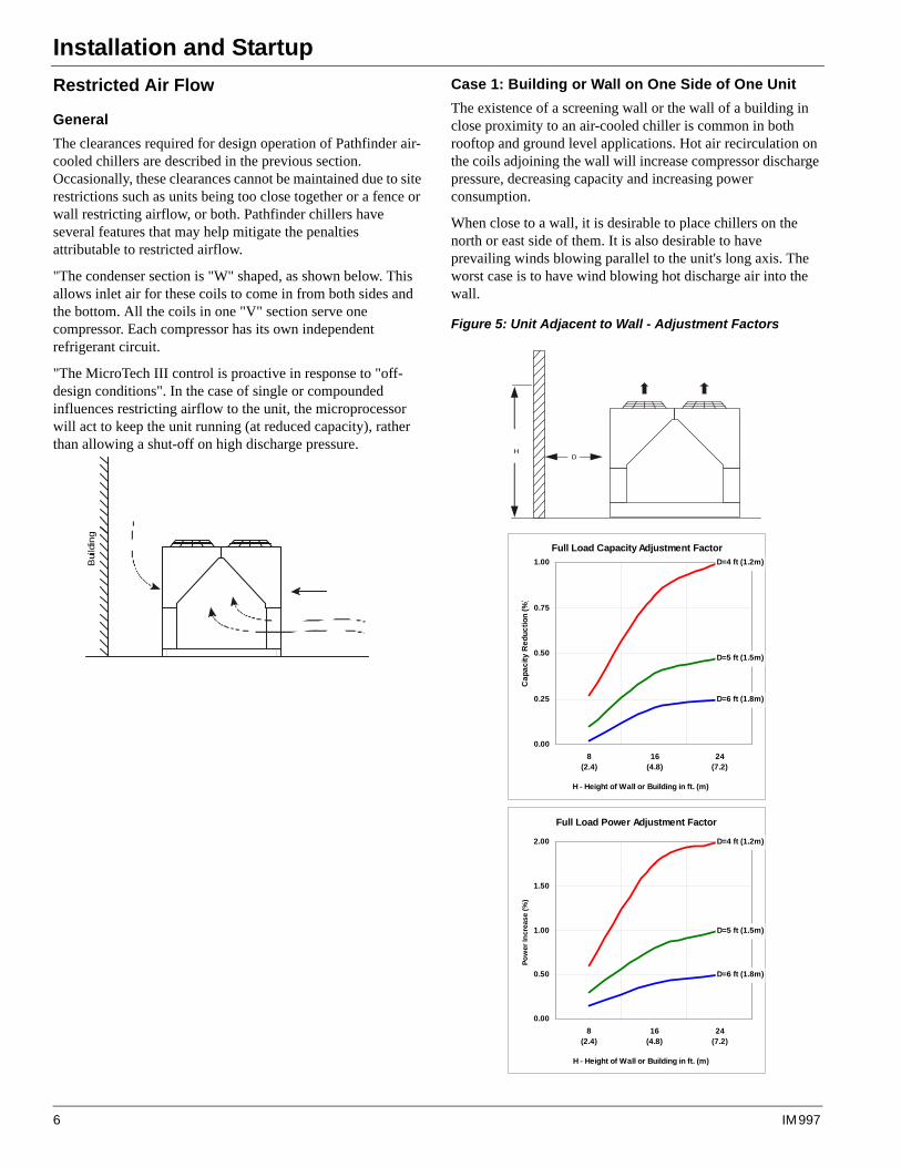
Case 1: Building or Wall on One Side of One Unit
The existence of a screening wall or the wall of a building in close proximity to an air-cooled chiller is common in both rooftop and ground level applications. Hot air recirculation on the coils adjoining the wall will increase compressor discharge pressure, decreasing capacity and increasing power consumption.
When close to a wall, it is desirable to place chillers on the north or east side of them. It is also desirable to have prevailing winds blowing parallel to the unit's long axis. The worst case is to have wind blowing hot discharge air into the wall.
Figure 5: Unit Adjacent to Wall - Adjustment Factors
Bui
ldin
g
Full Load Capacity Adjustment FactorD=4 ft (1.2m)
D=5 ft (1.5m)
D=6 ft (1.8m)
0.00
0.25
0.50
0.75
1.00
8(2.4)
16(4.8)
24(7.2)
H - Height of Wall or Building in ft. (m)
Ca
pa
cit
y R
ed
uc
tio
n (
%)
Full Load Power Adjustment Factor
D=4 ft (1.2m)
D=5 ft (1.5m)
D=6 ft (1.8m)
0.00
0.50
1.00
1.50
2.00
8(2.4)
16(4.8)
24(7.2)
H - Height of Wall or Building in ft. (m)
Po
wer
Incr
ease
(%
)
HD
6 IM 997
Installation and Startup
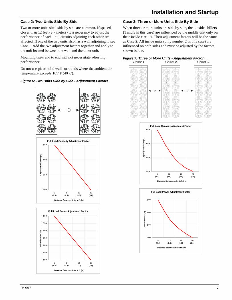
Case 2: Two Units Side By Side
Two or more units sited side by side are common. If spaced closer than 12 feet (3.7 meters) it is necessary to adjust the performance of each unit; circuits adjoining each other are affected. If one of the two units also has a wall adjoining it, see Case 1. Add the two adjustment factors together and apply to the unit located between the wall and the other unit.
Mounting units end to end will not necessitate adjusting performance.
Do not use pit or solid wall surrounds where the ambient air temperature exceeds 105F (40C).
Figure 6: Two Units Side by Side - Adjustment Factors
Case 3: Three or More Units Side By Side
When three or more units are side by side, the outside chillers (1 and 3 in this case) are influenced by the middle unit only on their inside circuits. Their adjustment factors will be the same as Case 2. All inside units (only number 2 in this case) are influenced on both sides and must be adjusted by the factors shown below.
Figure 7: Three or More Units - Adjustment Factor
Full Load Capacity Adjustment Factor
0.00
0.50
1.00
1.50
6(1.8)
8(2.4)
10(3.0)
12(3.6)
Distance Between Units in ft. (m)
Ca
pa
cit
y R
ed
uc
tio
n (
%)
Full Load Power Adjustment Factor
0.00
0.50
1.00
1.50
2.00
2.50
3.00
6(1.8)
8(2.4)
10(3.0)
12(3.6)
Distance Between Units in ft. (m)
Po
wer
Incr
ease
(%
)
Full Load Capacity Adjustment Factor
0.00
1.00
2.00
3.00
8(2.4)
12(3.6)
16(4.8)
20(6.1)
Distance Between Units in ft. (m)
Ca
pa
cit
y R
ed
uc
tio
n (
%)
Full Load Power Adjustment Factor
0.00
2.00
4.00
6.00
8(2.4)
12(3.6)
16(4.8)
20(6.1)
Distance Between Units in ft. (m)
Po
wer
Incr
ease
(%
)
IM 997 7
Installation and Startup
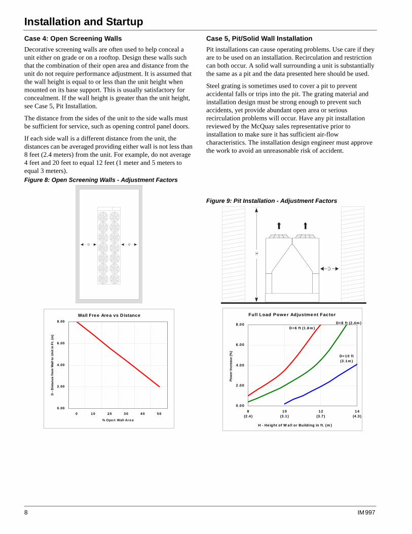
Case 4: Open Screening Walls
Decorative screening walls are often used to help conceal a unit either on grade or on a rooftop. Design these walls such that the combination of their open area and distance from the unit do not require performance adjustment. It is assumed that the wall height is equal to or less than the unit height when mounted on its base support. This is usually satisfactory for concealment. If the wall height is greater than the unit height, see Case 5, Pit Installation.
The distance from the sides of the unit to the side walls must be sufficient for service, such as opening control panel doors.
If each side wall is a different distance from the unit, the distances can be averaged providing either wall is not less than 8 feet (2.4 meters) from the unit. For example, do not average 4 feet and 20 feet to equal 12 feet (1 meter and 5 meters to equal 3 meters).Figure 8: Open Screening Walls - Adjustment Factors
Case 5, Pit/Solid Wall Installation
Pit installations can cause operating problems. Use care if they are to be used on an installation. Recirculation and restriction can both occur. A solid wall surrounding a unit is substantially the same as a pit and the data presented here should be used.
Steel grating is sometimes used to cover a pit to prevent accidental falls or trips into the pit. The grating material and installation design must be strong enough to prevent such accidents, yet provide abundant open area or serious recirculation problems will occur. Have any pit installation reviewed by the McQuay sales representative prior to installation to make sure it has sufficient air-flow characteristics. The installation design engineer must approve the work to avoid an unreasonable risk of accident.
Figure 9: Pit Installation - Adjustment Factors
Wall Free Area vs Distance
0.00
2 .00
4 .00
6 .00
8 .00
0 1 0 2 0 3 0 4 0 5 0
% Ope n Wall Ar e a
D -
Dis
tan
ce f
rom
Wal
l to
Un
it in
Ft.
(m
)
Full Load Powe r Adjustme nt Factor
D=6 ft (1 .8 m )
D=8 ft (2 .4m )
D= 10 ft (3 .1m )
0 .00
2 .00
4 .00
6 .00
8 .00
8(2 .4 )
10(3 .1 )
12(3 .7 )
14(4 .3 )
H - He ight of W all or Building in ft. (m )
Po
we
r In
crea
se
(%)
8 IM 997
Installation and Startup
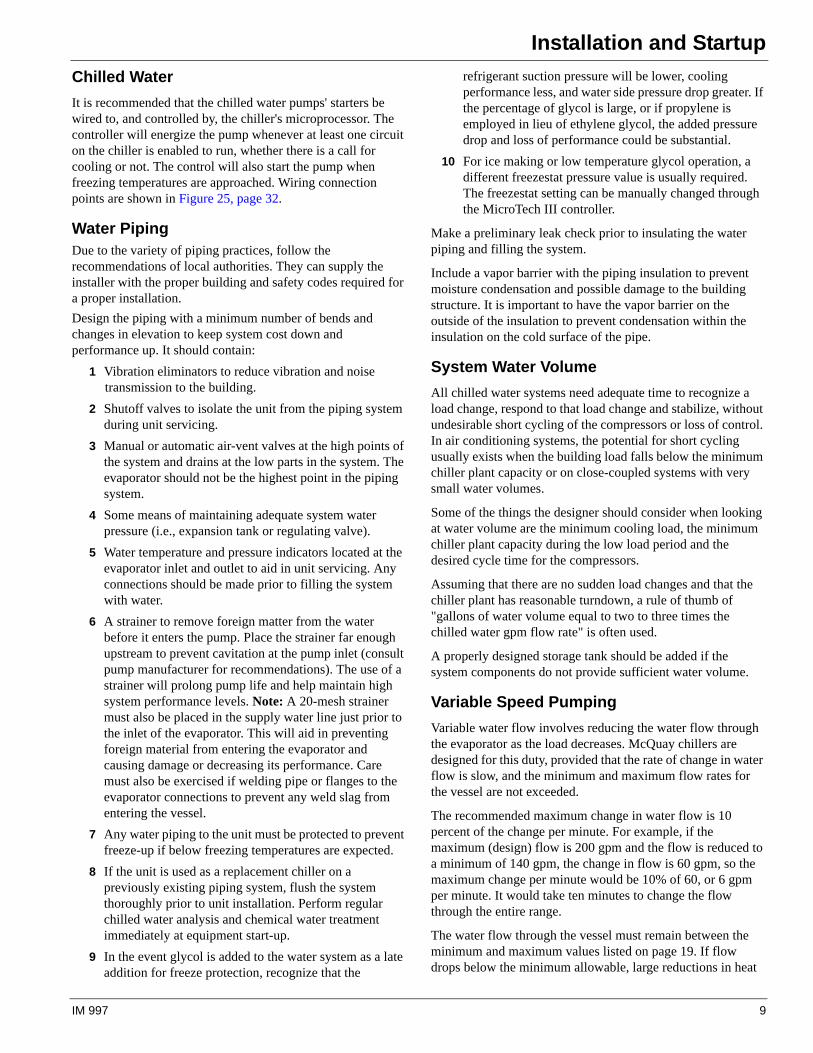
Chilled Water
It is recommended that the chilled water pumps' starters be wired to, and controlled by, the chiller's microprocessor. The controller will energize the pump whenever at least one circuit on the chiller is enabled to run, whether there is a call for cooling or not. The control will also start the pump when freezing temperatures are approached. Wiring connection points are shown in Figure 25, page 32.
Water PipingDue to the variety of piping practices, follow the recommendations of local authorities. They can supply the installer with the proper building and safety codes required for a proper installation.
Design the piping with a minimum number of bends and changes in elevation to keep system cost down and performance up. It should contain:
1 Vibration eliminators to reduce vibration and noise transmission to the building.
2 Shutoff valves to isolate the unit from the piping system during unit servicing.
3 Manual or automatic air-vent valves at the high points of the system and drains at the low parts in the system. The evaporator should not be the highest point in the piping system.
4 Some means of maintaining adequate system water pressure (i.e., expansion tank or regulating valve).
5 Water temperature and pressure indicators located at the evaporator inlet and outlet to aid in unit servicing. Any connections should be made prior to filling the system with water.
6 A strainer to remove foreign matter from the water before it enters the pump. Place the strainer far enough upstream to prevent cavitation at the pump inlet (consult pump manufacturer for recommendations). The use of a strainer will prolong pump life and help maintain high system performance levels. Note: A 20-mesh strainer must also be placed in the supply water line just prior to the inlet of the evaporator. This will aid in preventing foreign material from entering the evaporator and causing damage or decreasing its performance. Care must also be exercised if welding pipe or flanges to the evaporator connections to prevent any weld slag from entering the vessel.
7 Any water piping to the unit must be protected to prevent freeze-up if below freezing temperatures are expected.
8 If the unit is used as a replacement chiller on a previously existing piping system, flush the system thoroughly prior to unit installation. Perform regular chilled water analysis and chemical water treatment immediately at equipment start-up.
9 In the event glycol is added to the water system as a late addition for freeze protection, recognize that the
refrigerant suction pressure will be lower, cooling performance less, and water side pressure drop greater. If the percentage of glycol is large, or if propylene is employed in lieu of ethylene glycol, the added pressure drop and loss of performance could be substantial.
10 For ice making or low temperature glycol operation, a different freezestat pressure value is usually required. The freezestat setting can be manually changed through the MicroTech III controller.
Make a preliminary leak check prior to insulating the water piping and filling the system.
Include a vapor barrier with the piping insulation to prevent moisture condensation and possible damage to the building structure. It is important to have the vapor barrier on the outside of the insulation to prevent condensation within the insulation on the cold surface of the pipe.
System Water Volume
All chilled water systems need adequate time to recognize a load change, respond to that load change and stabilize, without undesirable short cycling of the compressors or loss of control. In air conditioning systems, the potential for short cycling usually exists when the building load falls below the minimum chiller plant capacity or on close-coupled systems with very small water volumes.
Some of the things the designer should consider when looking at water volume are the minimum cooling load, the minimum chiller plant capacity during the low load period and the desired cycle time for the compressors.
Assuming that there are no sudden load changes and that the chiller plant has reasonable turndown, a rule of thumb of "gallons of water volume equal to two to three times the chilled water gpm flow rate" is often used.
A properly designed storage tank should be added if the system components do not provide sufficient water volume.
Variable Speed Pumping
Variable water flow involves reducing the water flow through the evaporator as the load decreases. McQuay chillers are designed for this duty, provided that the rate of change in water flow is slow, and the minimum and maximum flow rates for the vessel are not exceeded.
The recommended maximum change in water flow is 10 percent of the change per minute. For example, if the maximum (design) flow is 200 gpm and the flow is reduced to a minimum of 140 gpm, the change in flow is 60 gpm, so the maximum change per minute would be 10% of 60, or 6 gpm per minute. It would take ten minutes to change the flow through the entire range.
The water flow through the vessel must remain between the minimum and maximum values listed on page 19. If flow drops below the minimum allowable, large reductions in heat
IM 997 9
Installation and Startup
transfer can occur. If the flow exceeds the maximum rate, excessive pressure drop and tube erosion can occur.
Evaporator Freeze Protection
Pathfinder chillers are equipped with thermostatically controlled evaporator heaters that help protect against freeze-up down to -20°F (-28°C). For additional protection, at least one of the followingprocedures should be used during periods of sub-freezing temperatures:
1 Adding of a concentration of a glycol anti-freeze with a freeze point 10°F. below the lowest expected temperature. This will result in decreased capacity and increased pressure drop.
Note: Do not use automotive grade antifreezes as they contain inhibitors harmful to chilled water systems. Use only glycols specifically designated for use in building cooling systems.
2 Draining the water from outdoor equipment and piping and blowing the chiller tubes dry from the chiller. Do not energize the chiller heater when water is drained from the vessel.
3 Providing operation of the chilled water pump, circulating water through the chilled water system and through the evaporator
Note: The heaters come from the factory connected to the control power circuit. The control power can be rewired in the field to a separate 115V supply (do not wire directly to the heater). See the field wiring diagram on page 32. If this is done, it should power the entire control circuit. Mark the disconnect switch clearly to avoid accidental deactivation of the heater during freezing temperatures. Exposed chilled water piping also requires protection. If the evaporator is drained for winter freeze protection, the heaters must be de-energized to prevent heater burnout..
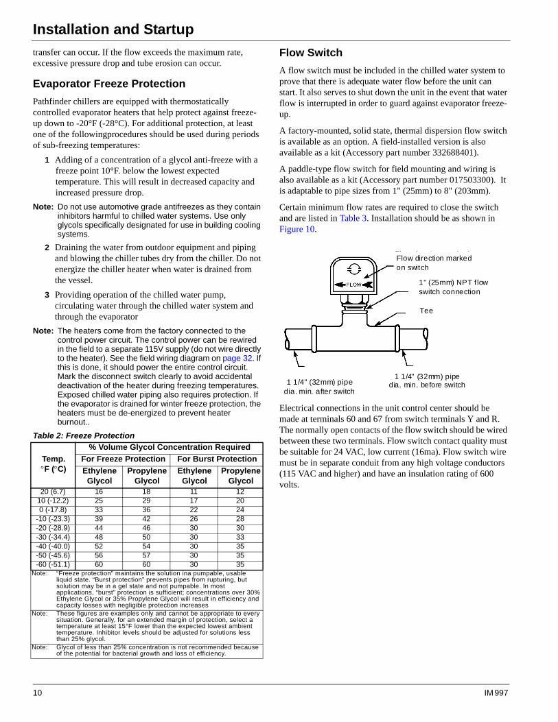
Flow Switch
A flow switch must be included in the chilled water system to prove that there is adequate water flow before the unit can start. It also serves to shut down the unit in the event that water flow is interrupted in order to guard against evaporator freeze-up.
A factory-mounted, solid state, thermal dispersion flow switch is available as an option. A field-installed version is also available as a kit (Accessory part number 332688401).
A paddle-type flow switch for field mounting and wiring is also available as a kit (Accessory part number 017503300). It is adaptable to pipe sizes from 1" (25mm) to 8" (203mm).
Certain minimum flow rates are required to close the switch and are listed in Table 3. Installation should be as shown in Figure 10.
Electrical connections in the unit control center should be made at terminals 60 and 67 from switch terminals Y and R. The normally open contacts of the flow switch should be wired between these two terminals. Flow switch contact quality must be suitable for 24 VAC, low current (16ma). Flow switch wire must be in separate conduit from any high voltage conductors (115 VAC and higher) and have an insulation rating of 600 volts.
Table 2: Freeze Protection
Temp.F (C)
% Volume Glycol Concentration Required
For Freeze Protection For Burst Protection
Ethylene Glycol
Propylene Glycol
Ethylene Glycol
Propylene Glycol
20 (6.7) 16 18 11 1210 (-12.2) 25 29 17 200 (-17.8) 33 36 22 24
-10 (-23.3) 39 42 26 28-20 (-28.9) 44 46 30 30-30 (-34.4) 48 50 30 33-40 (-40.0) 52 54 30 35-50 (-45.6) 56 57 30 35-60 (-51.1) 60 60 30 35
Note: “Freeze protection” maintains the solution ina pumpable, usable liquid state. “Burst protection” prevents pipes from rupturing, but solution may be in a gel state and not pumpable. In most applications, “burst” protection is sufficient; concentrations over 30% Ethylene Glycol or 35% Propylene Glycol will result in efficiency and capacity losses with negligible protection increases
Note: These figures are examples only and cannot be appropriate to every situation. Generally, for an extended margin of protection, select a temperature at least 15°F lower than the expected lowest ambient temperature. Inhibitor levels should be adjusted for solutions less than 25% glycol.
Note: Glycol of less than 25% concentration is not recommended because of the potential for bacterial growth and loss of efficiency.
Flow direction marked on switch
1" (25mm) NPT flow switch connection
Tee
1 1/4" (32mm) pipe dia. min. before switch 1 1/4" (32mm) pipe
dia. min. after switch
Flow direction marked on switch
1" (25mm) NPT f low switch connection
1 1/4" (32mm) pipe dia. min. before switch 1 1/4" (32mm) pipe
dia. min. after switch
Tee
10 IM 997
Installation and Startup
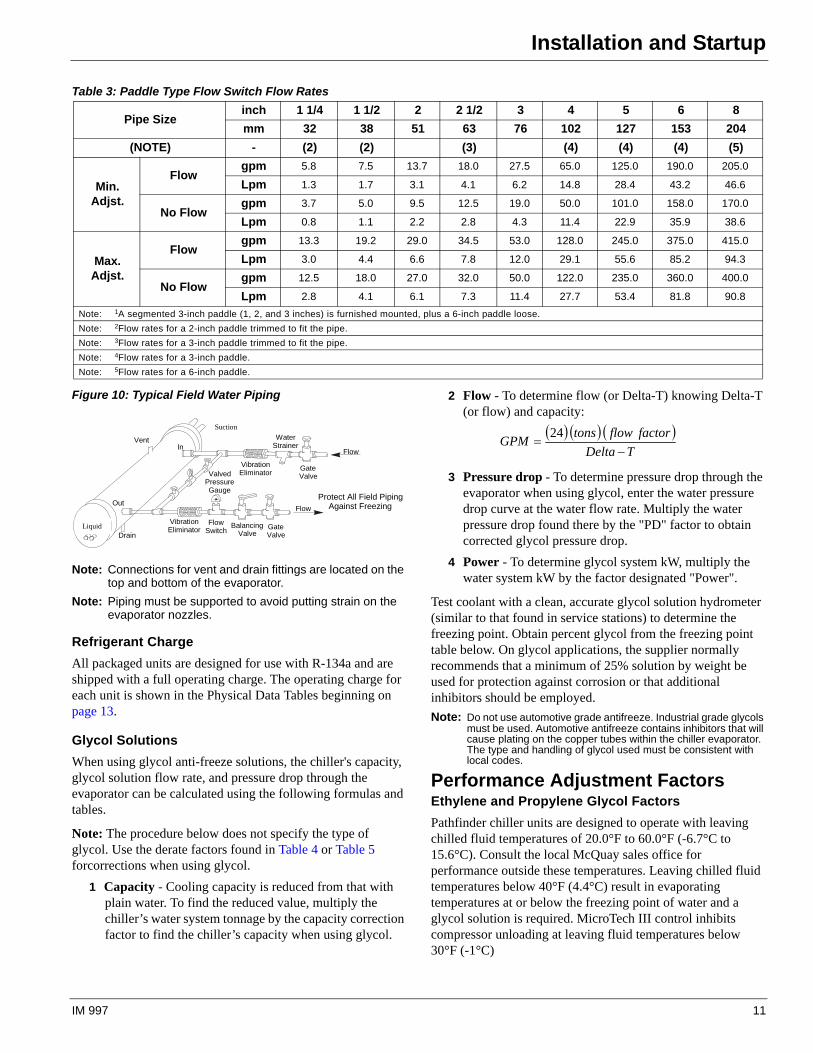
Figure 10: Typical Field Water Piping
Note: Connections for vent and drain fittings are located on the top and bottom of the evaporator.
Note: Piping must be supported to avoid putting strain on the evaporator nozzles.
Refrigerant Charge
All packaged units are designed for use with R-134a and are shipped with a full operating charge. The operating charge for each unit is shown in the Physical Data Tables beginning on page 13.
Glycol Solutions
When using glycol anti-freeze solutions, the chiller's capacity, glycol solution flow rate, and pressure drop through the evaporator can be calculated using the following formulas and tables.
Note: The procedure below does not specify the type of glycol. Use the derate factors found in Table 4 or Table 5 forcorrections when using glycol.
1 Capacity - Cooling capacity is reduced from that with plain water. To find the reduced value, multiply the chiller’s water system tonnage by the capacity correction factor to find the chiller’s capacity when using glycol.
2 Flow - To determine flow (or Delta-T) knowing Delta-T (or flow) and capacity:
3 Pressure drop - To determine pressure drop through the evaporator when using glycol, enter the water pressure drop curve at the water flow rate. Multiply the water pressure drop found there by the "PD" factor to obtain corrected glycol pressure drop.
4 Power - To determine glycol system kW, multiply the water system kW by the factor designated "Power".
Test coolant with a clean, accurate glycol solution hydrometer (similar to that found in service stations) to determine the freezing point. Obtain percent glycol from the freezing point table below. On glycol applications, the supplier normally recommends that a minimum of 25% solution by weight be used for protection against corrosion or that additional inhibitors should be employed.
Note: Do not use automotive grade antifreeze. Industrial grade glycols must be used. Automotive antifreeze contains inhibitors that will cause plating on the copper tubes within the chiller evaporator. The type and handling of glycol used must be consistent with local codes.
Performance Adjustment Factors Ethylene and Propylene Glycol Factors
Pathfinder chiller units are designed to operate with leaving chilled fluid temperatures of 20.0°F to 60.0°F (-6.7°C to 15.6°C). Consult the local McQuay sales office for performance outside these temperatures. Leaving chilled fluid temperatures below 40°F (4.4°C) result in evaporating temperatures at or below the freezing point of water and a glycol solution is required. MicroTech III control inhibits compressor unloading at leaving fluid temperatures below 30°F (-1°C)
Table 3: Paddle Type Flow Switch Flow Rates
Pipe Size inch 1 1/4 1 1/2 2 2 1/2 3 4 5 6 8
mm 32 38 51 63 76 102 127 153 204
(NOTE) - (2) (2) (3) (4) (4) (4) (5)
Min.Adjst.
Flowgpm 5.8 7.5 13.7 18.0 27.5 65.0 125.0 190.0 205.0
Lpm 1.3 1.7 3.1 4.1 6.2 14.8 28.4 43.2 46.6
No Flowgpm 3.7 5.0 9.5 12.5 19.0 50.0 101.0 158.0 170.0
Lpm 0.8 1.1 2.2 2.8 4.3 11.4 22.9 35.9 38.6
Max.Adjst.
Flowgpm 13.3 19.2 29.0 34.5 53.0 128.0 245.0 375.0 415.0
Lpm 3.0 4.4 6.6 7.8 12.0 29.1 55.6 85.2 94.3
No Flowgpm 12.5 18.0 27.0 32.0 50.0 122.0 235.0 360.0 400.0
Lpm 2.8 4.1 6.1 7.3 11.4 27.7 53.4 81.8 90.8
Note: 1A segmented 3-inch paddle (1, 2, and 3 inches) is furnished mounted, plus a 6-inch paddle loose.
Note: 2Flow rates for a 2-inch paddle trimmed to fit the pipe.
Note: 3Flow rates for a 3-inch paddle trimmed to fit the pipe.
Note: 4Flow rates for a 3-inch paddle.
Note: 5Flow rates for a 6-inch paddle.
Vent
Drain
GateValve
WaterStrainer
VibrationEliminatorValved
PressureGauge
In
OutProtect All Field Piping
Against Freezing
Flow
VibrationEliminator
FlowSwitch
BalancingValve
GateValve
Flow
Liquid
Suction TDelta
factorflowtonsGPM
24
IM 997 11
Installation and Startup
.
Electrical Connections
All wiring must be done in accordance with applicable local and national codes. Pathfinder units can be ordered with either standard multi-point power or optional single point power connections and with various disconnect and circuit breaker options. Wiring within the unit is sized in accordance with the U.S.A. National Electrical Code. Field-supplied disconnect switches are required if not factory-supplied with the unit.
Note: Disconnect switches are molded case construction with lockable through-the-door handles. They can be used to remove the unit/circuit from the power system.
Note: The individual compressor isolation circuit breakers for each circuit isolate the compressor and do not have through-the-door handles. They are operable only after the panel doors are opened.
Note: The high short circuit rated panel means that a short circuit current up to the ratings shown in Table 8, Interrupt Ratings (kAmps)will be contained in the panel. There is a short period of time when the circuit breaker will short circuit before opening a circuit that can damage downstream components. In other words, the enclosure is stronger than a standard enclosure. It has a high interrupt rated disconnect switch.
Note: The factory-mounted control power transformer is protected by fuses.Note: Condenser fans are protected and isolated by circuit breakers.
Disconnecting means are addressed by Article 440 of the U.S.A. National Electrical Code (NEC), which requires “disconnecting means capable of disconnecting air conditioning and refrigerating equipment including motor-compressors, and controllers from the circuit feeder.” Select and locate the disconnect switch per the NEC guidelines. Maximum recommended fuse sizes are given in the electrical data tables of this catalog for help in sizing the disconnect.
Terminals are provided in a unit control panel for optional field hookup of the control circuit to a separate fused 115-volt power supply in lieu of the standard factory installed control transformer.
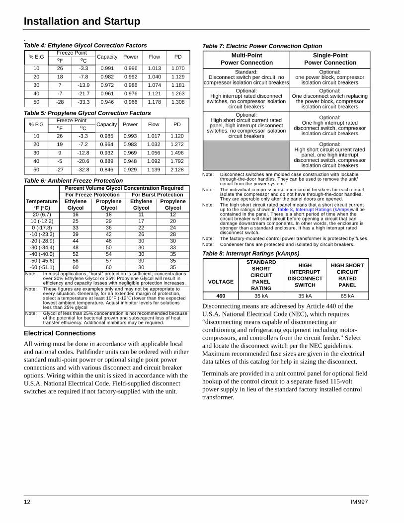
Table 4: Ethylene Glycol Correction Factors
% E.GFreeze Point
Capacity Power Flow PDoF oC
10 26 -3.3 0.991 0.996 1.013 1.070
20 18 -7.8 0.982 0.992 1.040 1.129
30 7 -13.9 0.972 0.986 1.074 1.181
40 -7 -21.7 0.961 0.976 1.121 1.263
50 -28 -33.3 0.946 0.966 1.178 1.308
Table 5: Propylene Glycol Correction Factors
% P.GFreeze Point
Capacity Power Flow PDoF oC
10 26 -3.3 0.985 0.993 1.017 1.120
20 19 -7.2 0.964 0.983 1.032 1.272
30 9 -12.8 0.932 0.969 1.056 1.496
40 -5 -20.6 0.889 0.948 1.092 1.792
50 -27 -32.8 0.846 0.929 1.139 2.128
Table 6: Ambient Freeze Protection
TemperatureF (C)
Percent Volume Glycol Concentration RequiredFor Freeze Protection For Burst ProtectionEthylene
GlycolPropylene
GlycolEthylene
GlycolPropylene
Glycol20 (6.7) 16 18 11 12
10 (-12.2) 25 29 17 200 (-17.8) 33 36 22 24
-10 (-23.3) 39 42 26 28-20 (-28.9) 44 46 30 30-30 (-34.4) 48 50 30 33-40 (-40.0) 52 54 30 35-50 (-45.6) 56 57 30 35-60 (-51.1) 60 60 30 35
Note: In most applications, “burst” protection is sufficient; concentrations over 30% Ethylene Glycol or 35% Propylene Glycol will result in efficiency and capacity losses with negligible protection increases.
Note: These figures are examples only and may not be appropriate to every situation. Generally, for an extended margin of protection, select a temperature at least 10°F (-12°C) lower than the expected lowest ambient temperature. Adjust inhibitor levels for solutions less than 25% glycol
Note: Glycol of less than 25% concentration is not recommended because of the potential for bacterial growth and subsequent loss of heat transfer efficiency. Additional inhibitors may be required.
Table 7: Electric Power Connection Option
Multi-PointPower Connection
Single-Point Power Connection
Standard:Disconnect switch per circuit, no
compressor isolation circuit breakers
Optional: one power block, compressor
isolation circuit breakers
Optional:High interrupt rated disconnect
switches, no compressor isolation circuit breakers
Optional:One disconnect switch replacing
the power block, compressor isolation circuit breakers
Optional: High short circuit current rated panel, high interrupt disconnect
switches, no compressor isolation circuit breakers
Optional:One high interrupt rated
disconnect switch, compressor isolation circuit breakers
Optional:High short circuit current rated
panel, one high interrupt disconnect switch, compressor
isolation circuit breakers
Table 8: Interrupt Ratings (kAmps)
VOLTAGE
STANDARD SHORT
CIRCUIT PANEL RATING
HIGH INTERRUPT
DISCONNECT SWITCH
HIGH SHORT CIRCUIT RATED PANEL
460 35 kA 35 kA 65 kA
12 IM 997
Physical Data
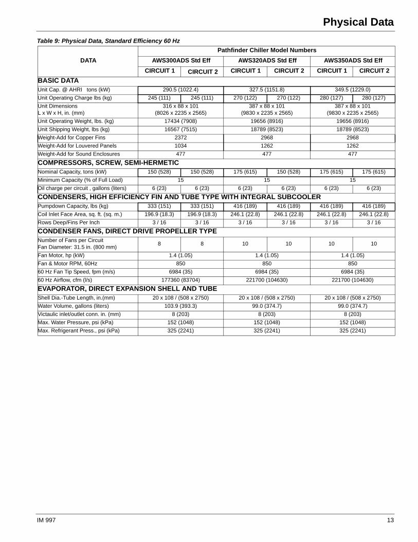
Physical DataTable 9: Physical Data, Standard Efficiency 60 Hz
DATA
Pathfinder Chiller Model Numbers
AWS300ADS Std Eff AWS320ADS Std Eff AWS350ADS Std Eff
CIRCUIT 1 CIRCUIT 2 CIRCUIT 1 CIRCUIT 2 CIRCUIT 1 CIRCUIT 2
BASIC DATAUnit Cap. @ AHRI tons (kW) 290.5 (1022.4) 327.5 (1151.8) 349.5 (1229.0)
Unit Operating Charge lbs (kg) 245 (111) 245 (111) 270 (122) 270 (122) 280 (127) 280 (127)
Unit DimensionsL x W x H, in. (mm)
316 x 88 x 101(8026 x 2235 x 2565)
387 x 88 x 101(9830 x 2235 x 2565)
387 x 88 x 101(9830 x 2235 x 2565)
Unit Operating Weight, lbs. (kg) 17434 (7908) 19656 (8916) 19656 (8916)
Unit Shipping Weight, lbs (kg) 16567 (7515) 18789 (8523) 18789 (8523)
Weight-Add for Copper Fins 2372 2968 2968
Weight-Add for Louvered Panels 1034 1262 1262
Weight-Add for Sound Enclosures 477 477 477
COMPRESSORS, SCREW, SEMI-HERMETICNominal Capacity, tons (kW) 150 (528) 150 (528) 175 (615) 150 (528) 175 (615) 175 (615)
Minimum Capacity (% of Full Load) 15 15 15
Oil charge per circuit , gallons (liters) 6 (23) 6 (23) 6 (23) 6 (23) 6 (23) 6 (23)
CONDENSERS, HIGH EFFICIENCY FIN AND TUBE TYPE WITH INTEGRAL SUBCOOLERPumpdown Capacity, lbs (kg) 333 (151) 333 (151) 416 (189) 416 (189) 416 (189) 416 (189)
Coil Inlet Face Area, sq. ft. (sq. m.) 196.9 (18.3) 196.9 (18.3) 246.1 (22.8) 246.1 (22.8) 246.1 (22.8) 246.1 (22.8)
Rows Deep/Fins Per Inch 3 / 16 3 / 16 3 / 16 3 / 16 3 / 16 3 / 16
CONDENSER FANS, DIRECT DRIVE PROPELLER TYPENumber of Fans per Circuit Fan Diameter: 31.5 in. (800 mm)
8 8 10 10 10 10
Fan Motor, hp (kW) 1.4 (1.05) 1.4 (1.05) 1.4 (1.05)
Fan & Motor RPM, 60Hz 850 850 850
60 Hz Fan Tip Speed, fpm (m/s) 6984 (35) 6984 (35) 6984 (35)
60 Hz Airflow, cfm (l/s) 177360 (83704) 221700 (104630) 221700 (104630)
EVAPORATOR, DIRECT EXPANSION SHELL AND TUBEShell Dia.-Tube Length, in.(mm) 20 x 108 / (508 x 2750) 20 x 108 / (508 x 2750) 20 x 108 / (508 x 2750)
Water Volume, gallons (liters) 103.9 (393.3) 99.0 (374.7) 99.0 (374.7)
Victaulic inlet/outlet conn. in. (mm) 8 (203) 8 (203) 8 (203)
Max. Water Pressure, psi (kPa) 152 (1048) 152 (1048) 152 (1048)
Max. Refrigerant Press., psi (kPa) 325 (2241) 325 (2241) 325 (2241)
IM 997 13
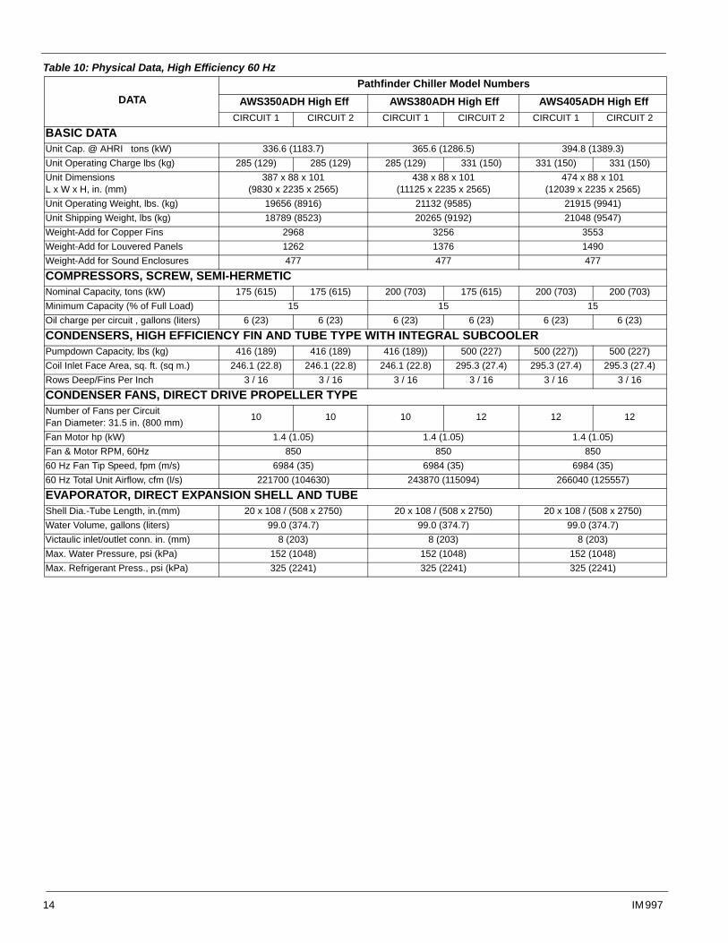
Table 10: Physical Data, High Efficiency 60 Hz
DATA
Pathfinder Chiller Model Numbers
AWS350ADH High Eff AWS380ADH High Eff AWS405ADH High Eff
CIRCUIT 1 CIRCUIT 2 CIRCUIT 1 CIRCUIT 2 CIRCUIT 1 CIRCUIT 2
BASIC DATAUnit Cap. @ AHRI tons (kW) 336.6 (1183.7) 365.6 (1286.5) 394.8 (1389.3)
Unit Operating Charge lbs (kg) 285 (129) 285 (129) 285 (129) 331 (150) 331 (150) 331 (150)
Unit DimensionsL x W x H, in. (mm)
387 x 88 x 101(9830 x 2235 x 2565)
438 x 88 x 101(11125 x 2235 x 2565)
474 x 88 x 101(12039 x 2235 x 2565)
Unit Operating Weight, lbs. (kg) 19656 (8916) 21132 (9585) 21915 (9941)
Unit Shipping Weight, lbs (kg) 18789 (8523) 20265 (9192) 21048 (9547)
Weight-Add for Copper Fins 2968 3256 3553
Weight-Add for Louvered Panels 1262 1376 1490
Weight-Add for Sound Enclosures 477 477 477
COMPRESSORS, SCREW, SEMI-HERMETICNominal Capacity, tons (kW) 175 (615) 175 (615) 200 (703) 175 (615) 200 (703) 200 (703)
Minimum Capacity (% of Full Load) 15 15 15
Oil charge per circuit , gallons (liters) 6 (23) 6 (23) 6 (23) 6 (23) 6 (23) 6 (23)
CONDENSERS, HIGH EFFICIENCY FIN AND TUBE TYPE WITH INTEGRAL SUBCOOLERPumpdown Capacity, lbs (kg) 416 (189) 416 (189) 416 (189)) 500 (227) 500 (227)) 500 (227)
Coil Inlet Face Area, sq. ft. (sq m.) 246.1 (22.8) 246.1 (22.8) 246.1 (22.8) 295.3 (27.4) 295.3 (27.4) 295.3 (27.4)
Rows Deep/Fins Per Inch 3 / 16 3 / 16 3 / 16 3 / 16 3 / 16 3 / 16
CONDENSER FANS, DIRECT DRIVE PROPELLER TYPENumber of Fans per Circuit Fan Diameter: 31.5 in. (800 mm)
10 10 10 12 12 12
Fan Motor hp (kW) 1.4 (1.05) 1.4 (1.05) 1.4 (1.05)
Fan & Motor RPM, 60Hz 850 850 850
60 Hz Fan Tip Speed, fpm (m/s) 6984 (35) 6984 (35) 6984 (35)
60 Hz Total Unit Airflow, cfm (l/s) 221700 (104630) 243870 (115094) 266040 (125557)
EVAPORATOR, DIRECT EXPANSION SHELL AND TUBEShell Dia.-Tube Length, in.(mm) 20 x 108 / (508 x 2750) 20 x 108 / (508 x 2750) 20 x 108 / (508 x 2750)
Water Volume, gallons (liters) 99.0 (374.7) 99.0 (374.7) 99.0 (374.7)
Victaulic inlet/outlet conn. in. (mm) 8 (203) 8 (203) 8 (203)
Max. Water Pressure, psi (kPa) 152 (1048) 152 (1048) 152 (1048)
Max. Refrigerant Press., psi (kPa) 325 (2241) 325 (2241) 325 (2241)
14 IM 997
Dimensions
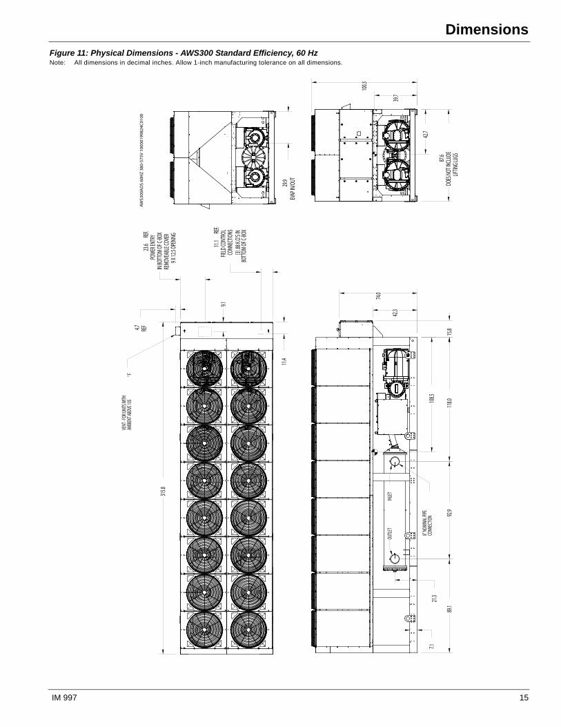
DimensionsFigure 11: Physical Dimensions - AWS300 Standard Efficiency, 60 Hz Note: All dimensions in decimal inches. Allow 1-inch manufacturing tolerance on all dimensions.
108.5
42.3
21.3
92.9
118.0
89.1
15.8
74.0
7.18"
NOMI
NAL P
IPECO
NNEC
TION
INLET
OUTLE
T
11.4
11.1
REF.
FIELD
CONT
ROL
CONN
ECTIO
NS(3)
.88 K.O
.'S IN
BOTT
OM OF
C-BO
X
9.1
23.6
REF.
POWE
R ENT
RYIN
BOTT
OM OF
C-BO
XRE
MOVE
ABLE
COVE
R9 X
12.5 O
PENIN
G
4.7 REF
315.8
VENT
- FOR
UNITS
WITH
AMBIE
NT AB
OVE 1
05°F
39.7
42.7
87.6
DOES
NOT IN
CLUD
ELIF
TING L
UGS
100.3
29.9
EVAP
IN/O
UT
AWS3
00A
DS
60H
Z 38
0-57
5V 1
0000
1998
24C0
100
IM 997 15
Dimensions
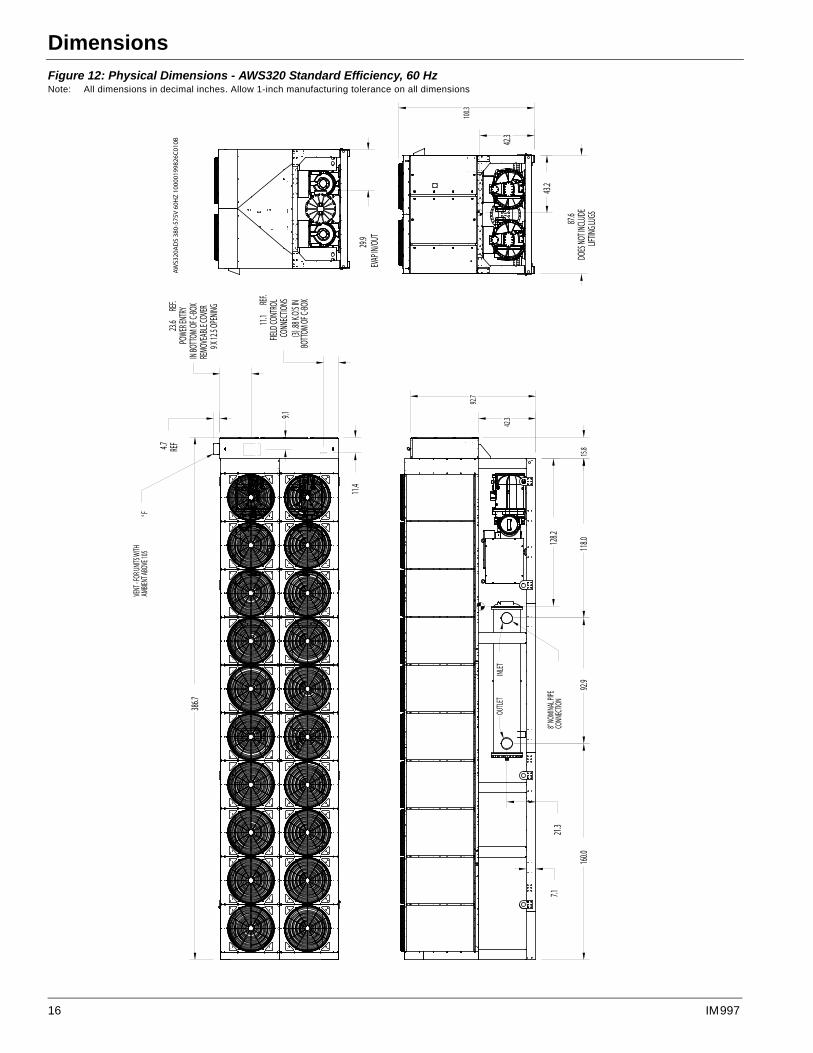
Figure 12: Physical Dimensions - AWS320 Standard Efficiency, 60 Hz Note: All dimensions in decimal inches. Allow 1-inch manufacturing tolerance on all dimensions
128.2
21.3
92.9
118.0
160.0
7.1
92.7
42.3
15.8
8" NO
MINA
L PIPE
CONN
ECTIO
N
INLET
OUTLE
T
11.4
11.1
REF.
FIELD
CONT
ROL
CONN
ECTIO
NS(3)
.88 K.O
.'S IN
BOTT
OM OF
C-BO
X
9.1
23.6
REF.
POWE
R ENT
RYIN
BOTT
OM OF
C-BO
XRE
MOVE
ABLE
COVE
R9 X
12.5 O
PENIN
G
4.7 REF
386.7
VENT
- FOR
UNITS
WITH
AMBIE
NT AB
OVE 1
05°F
42.3
43.2
87.6
DOES
NOT IN
CLUD
ELIF
TING L
UGS
100.3
29.9
EVAP
IN/O
UT
AWS3
20A
DS
380-
575V
60H
Z 10
0001
9982
6C01
0B
16 IM 997
Dimensions
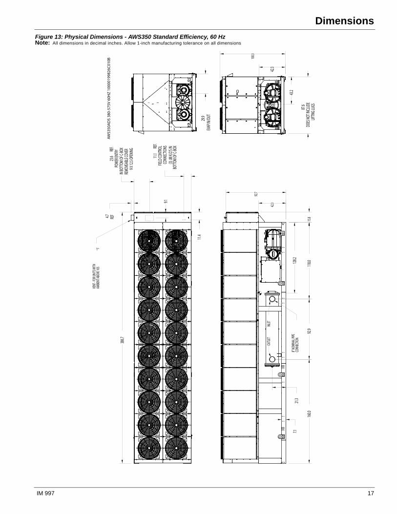
Figure 13: Physical Dimensions - AWS350 Standard Efficiency, 60 HzNote: All dimensions in decimal inches. Allow 1-inch manufacturing tolerance on all dimensions
128.2
21.3
92.9
118.0
160.0
7.1
92.7
42.3
15.8
8" NO
MINA
L PIPE
CONN
ECTIO
N
INLET
OUTLE
T
11.4
11.1
REF.
FIELD
CONT
ROL
CONN
ECTIO
NS(3)
.88 K.O
.'S IN
BOTT
OM OF
C-BO
X
9.1
23.6
REF.
POWE
R ENT
RYIN
BOTT
OM OF
C-BO
XRE
MOVE
ABLE
COVE
R9 X
12.5 O
PENIN
G
4.7 REF
386.7
VENT
- FOR
UNITS
WITH
AMBIE
NT AB
OVE 1
05°F
42.3
43.2
87.6
DOES
NOT IN
CLUD
ELIF
TING L
UGS
100.3
29.9
EVAP
IN/O
UT
AWS3
50A
DS
380-
575V
60H
Z 10
0001
9982
6C01
0B
IM 997 17

Dimensions
Figure 14: Physical Dimensions - AWS350 High Efficiency, 60 Hz Note: All dimensions in decimal inches. Allow 1-inch manufacturing tolerance on all dimensions
128.2
21.3
92.9
118.0
160.0
7.1
92.7
42.3
15.8
8" NO
MINA
L PIPE
CONN
ECTIO
N
INLET
OUTLE
T
11.4
11.1
REF.
FIELD
CONT
ROL
CONN
ECTIO
NS(3)
.88 K.O
.'S IN
BOTT
OM OF
C-BO
X
9.1
23.6
REF.
POWE
R ENT
RYIN
BOTT
OM OF
C-BO
XRE
MOVE
ABLE
COVE
R9 X
12.5 O
PENIN
G
4.7 REF
386.7
VENT
- FOR
UNITS
WITH
AMBIE
NT AB
OVE 1
05°F
42.3
43.2
87.6
DOES
NOT IN
CLUD
ELIF
TING L
UGS
100.3
29.9
EVAP
IN/O
UT
AWS3
50A
DH
208
-575
V 60
HZ
1000
0199
826C
010B
18 IM 997
Dimensions
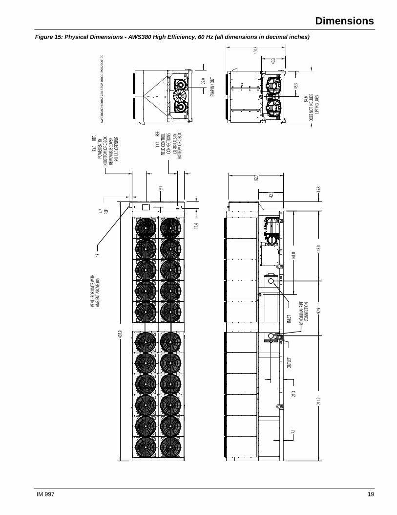
Figure 15: Physical Dimensions - AWS380 High Efficiency, 60 Hz (all dimensions in decimal inches)
EVAP
IN / O
UT
141.0
42.3
211.2
92.9
118.0
15.8
7.121
.3
92.7
OUTLE
TINL
ET
8" NO
MINA
L PIPE
CONN
ECTIO
N
11.4
11.1
REF.
FIELD
CONT
ROL
CONN
ECTIO
NS(3)
.88 K.O
.'S IN
BOTT
OM OF
C-BO
X
9.1
23.6
REF.
POWE
R ENT
RYIN
BOTT
OM OF
C-BO
XRE
MOVA
BLE C
OVER
9 X 12
.5 OPE
NING
437.9
VENT
- FOR
UNITS
WITH
AMBIE
NT AB
OVE 1
05°F
43.3
40.3
29.9
4.7 REF
87.6
DOES
NOT IN
CLUD
ELIF
TING L
UGS
100.3
AWS3
80A
DH
60H
Z 28
0-57
5V 1
0000
1998
27C0
100
IM 997 19
Dimensions
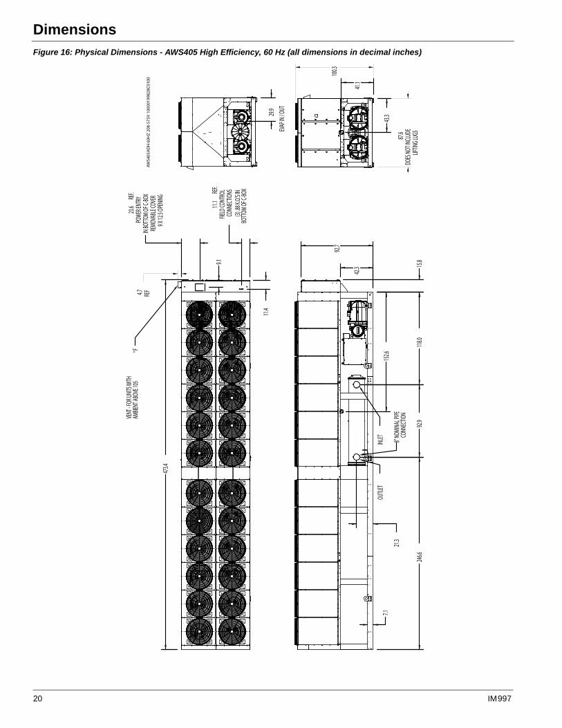
Figure 16: Physical Dimensions - AWS405 High Efficiency, 60 Hz (all dimensions in decimal inches)
EVAP
IN / O
UT
152.6
42.3
246.6
92.9
118.0
15.8
7.1
21.3
92.7
OUTLE
TINL
ET 8" NO
MINA
L PIPE
CONN
ECTIO
N
11.4
11.1
REF.
FIELD
CONT
ROL
CONN
ECTIO
NS(3)
.88 K.O
.'S IN
BOTT
OM OF
C-BO
X
9.1
23.6
REF.
POWE
R ENT
RYIN
BOTT
OM OF
C-BO
XRE
MOVA
BLE C
OVER
9 X 12
.5 OPE
NING
473.4
VENT
- FOR
UNITS
WITH
AMBIE
NT AB
OVE 1
05°F
43.3
41.1
29.9
4.7 REF
87.6
DOES
NOT IN
CLUD
ELIF
TING L
UGS
100.3
AWS4
05A
DH
60H
Z 20
8-57
5V 1
0000
1998
28C0
100
20 IM 997
Lifting & Mounting Weights
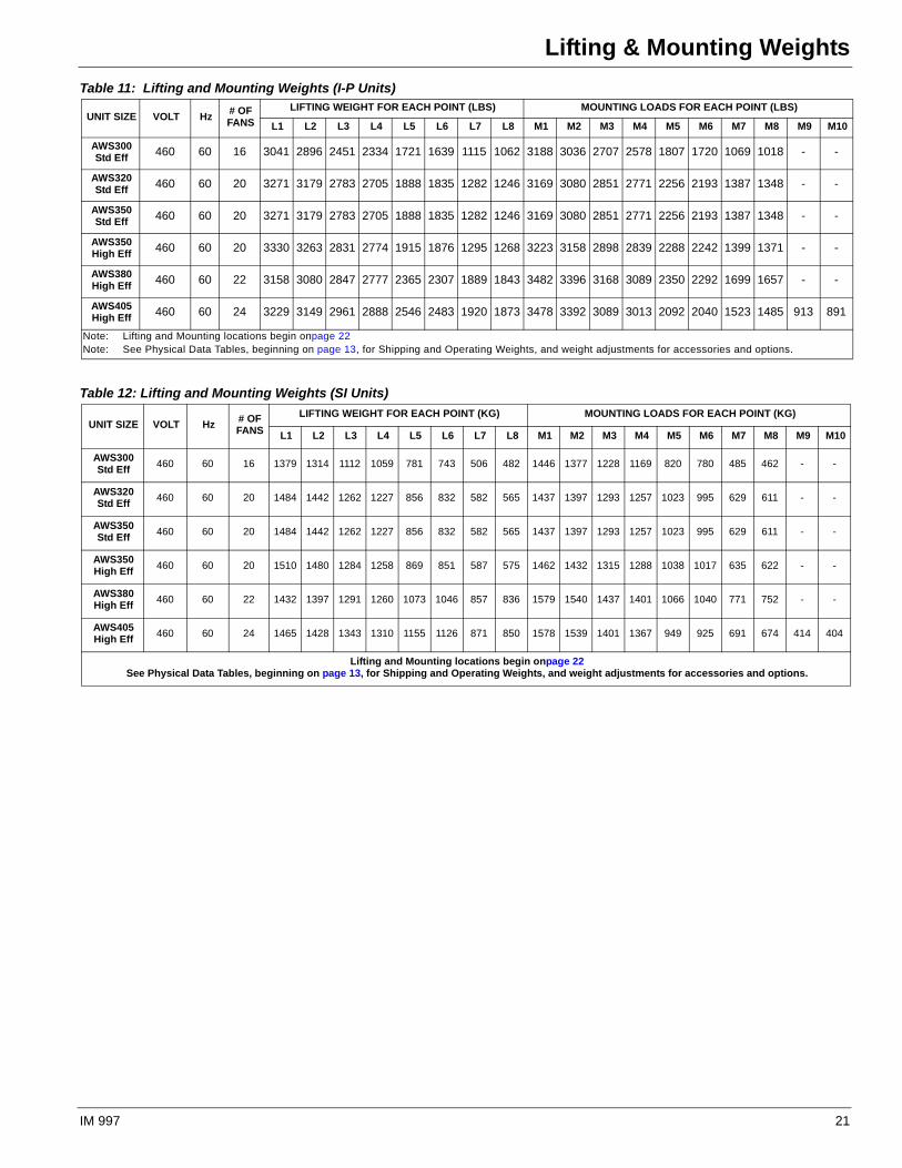
Lifting & Mounting WeightsTable 11: Lifting and Mounting Weights (I-P Units)
UNIT SIZE VOLT Hz# OF FANS
LIFTING WEIGHT FOR EACH POINT (LBS) MOUNTING LOADS FOR EACH POINT (LBS)
L1 L2 L3 L4 L5 L6 L7 L8 M1 M2 M3 M4 M5 M6 M7 M8 M9 M10
AWS300Std Eff 460 60 16 3041 2896 2451 2334 1721 1639 1115 1062 3188 3036 2707 2578 1807 1720 1069 1018 - -
AWS320Std Eff 460 60 20 3271 3179 2783 2705 1888 1835 1282 1246 3169 3080 2851 2771 2256 2193 1387 1348 - -
AWS350Std Eff 460 60 20 3271 3179 2783 2705 1888 1835 1282 1246 3169 3080 2851 2771 2256 2193 1387 1348 - -
AWS350High Eff 460 60 20 3330 3263 2831 2774 1915 1876 1295 1268 3223 3158 2898 2839 2288 2242 1399 1371 - -
AWS380High Eff 460 60 22 3158 3080 2847 2777 2365 2307 1889 1843 3482 3396 3168 3089 2350 2292 1699 1657 - -
AWS405High Eff 460 60 24 3229 3149 2961 2888 2546 2483 1920 1873 3478 3392 3089 3013 2092 2040 1523 1485 913 891
Note: Lifting and Mounting locations begin onpage 22Note: See Physical Data Tables, beginning on page 13, for Shipping and Operating Weights, and weight adjustments for accessories and options.
Table 12: Lifting and Mounting Weights (SI Units)
UNIT SIZE VOLT Hz# OF FANS
LIFTING WEIGHT FOR EACH POINT (KG) MOUNTING LOADS FOR EACH POINT (KG)
L1 L2 L3 L4 L5 L6 L7 L8 M1 M2 M3 M4 M5 M6 M7 M8 M9 M10
AWS300Std Eff
460 60 16 1379 1314 1112 1059 781 743 506 482 1446 1377 1228 1169 820 780 485 462 - -
AWS320Std Eff
460 60 20 1484 1442 1262 1227 856 832 582 565 1437 1397 1293 1257 1023 995 629 611 - -
AWS350Std Eff
460 60 20 1484 1442 1262 1227 856 832 582 565 1437 1397 1293 1257 1023 995 629 611 - -
AWS350High Eff
460 60 20 1510 1480 1284 1258 869 851 587 575 1462 1432 1315 1288 1038 1017 635 622 - -
AWS380High Eff
460 60 22 1432 1397 1291 1260 1073 1046 857 836 1579 1540 1437 1401 1066 1040 771 752 - -
AWS405High Eff
460 60 24 1465 1428 1343 1310 1155 1126 871 850 1578 1539 1401 1367 949 925 691 674 414 404
Lifting and Mounting locations begin onpage 22See Physical Data Tables, beginning on page 13, for Shipping and Operating Weights, and weight adjustments for accessories and options.
IM 997 21
Lifting and Mounting Locations
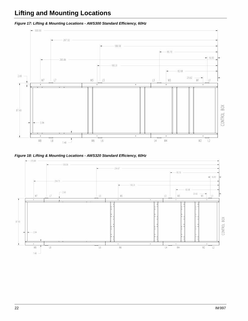
Lifting and Mounting LocationsFigure 17: Lifting & Mounting Locations - AWS300 Standard Efficiency, 60Hz
Figure 18: Lifting & Mounting Locations - AWS320 Standard Efficiency, 60Hz
22 IM 997
Lifting and Mounting Locations
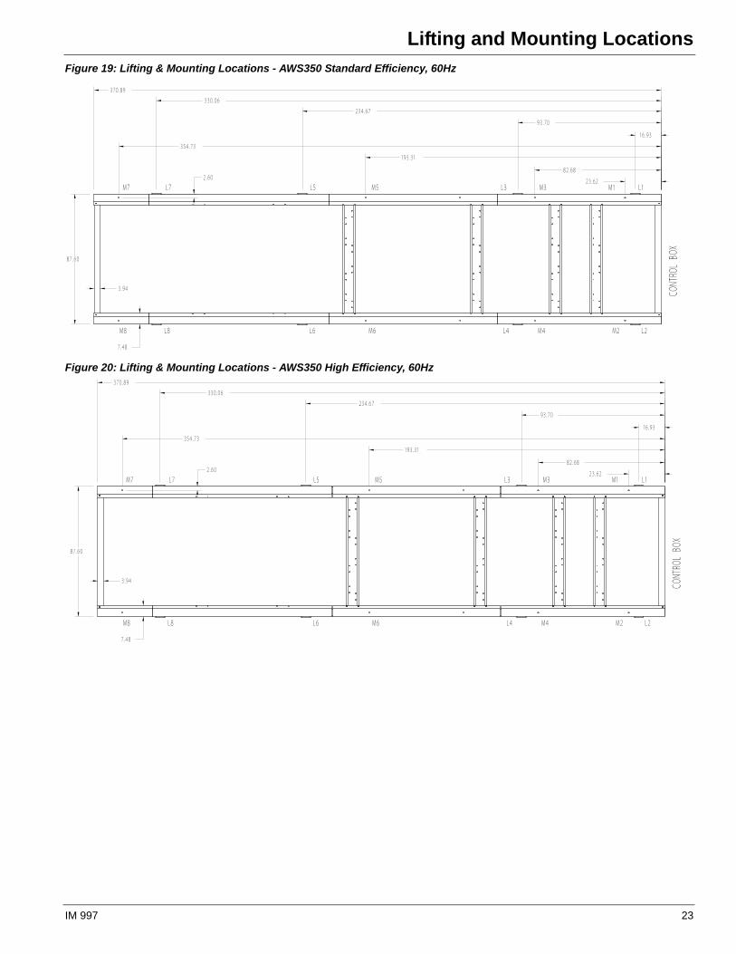
Figure 19: Lifting & Mounting Locations - AWS350 Standard Efficiency, 60Hz
Figure 20: Lifting & Mounting Locations - AWS350 High Efficiency, 60Hz
IM 997 23
Lifting and Mounting Locations
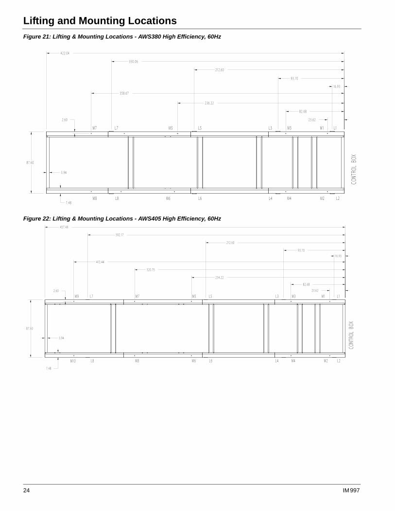
Figure 21: Lifting & Mounting Locations - AWS380 High Efficiency, 60Hz
Figure 22: Lifting & Mounting Locations - AWS405 High Efficiency, 60Hz
24 IM 997
Isolator Locations and Kit Numbers
Isolator Locations and Kit Numbers
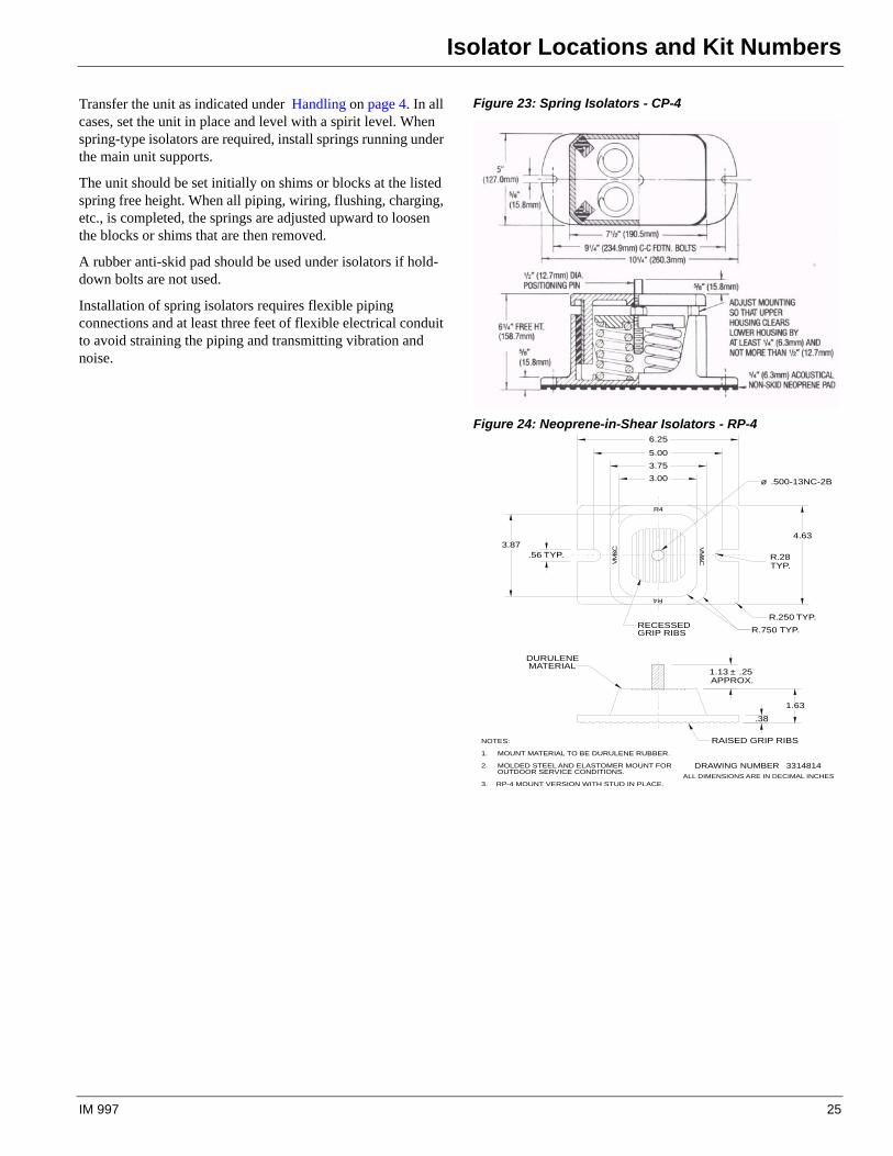
Transfer the unit as indicated under Handling on page 4. In all cases, set the unit in place and level with a spirit level. When spring-type isolators are required, install springs running under the main unit supports.
The unit should be set initially on shims or blocks at the listed spring free height. When all piping, wiring, flushing, charging, etc., is completed, the springs are adjusted upward to loosen the blocks or shims that are then removed.
A rubber anti-skid pad should be used under isolators if hold-down bolts are not used.
Installation of spring isolators requires flexible piping connections and at least three feet of flexible electrical conduit to avoid straining the piping and transmitting vibration and noise.
Figure 23: Spring Isolators - CP-4
Figure 24: Neoprene-in-Shear Isolators - RP-4
NOTES:
MOUNT MATERIAL TO BE DURULENE RUBBER.1.
MOLDED STEEL AND ELASTOMER MOUNT FOR2.OUTDOOR SERVICE CONDITIONS.
3. RP-4 MOUNT VERSION WITH STUD IN PLACE.ALL DIMENSIONS ARE IN DECIMAL INCHES
DRAWING NUMBER 3314814
1.13 ± .25APPROX.
1.63
.38
DURULENEMATERIAL
RAISED GRIP RIBS
3.00
3.75
5.00
6.25
3.87.56 TYP.
4.63
R.28TYP.
R.250 TYP.
R.750 TYP.RECESSEDGRIP RIBS
ø .500-13NC-2B
R4
R4
VM
&C
VM
&C
IM 997 25
Isolator Locations and Kit Numbers
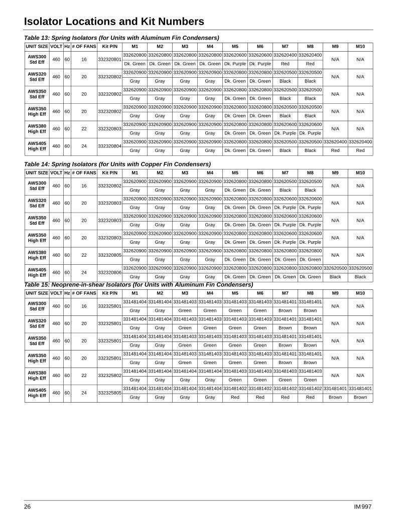
Table 13: Spring Isolators (for Units with Aluminum Fin Condensers)UNIT SIZE VOLT Hz # OF FANS Kit P/N M1 M2 M3 M4 M5 M6 M7 M8 M9 M10
AWS300Std Eff
460 60 16 332320801332620800 332620800 332620800 332620800 332620600 332620600 332620400 332620400
N/A N/ADk. Green Dk. Green Dk. Green Dk. Green Dk. Purple Dk. Purple Red Red
AWS320Std Eff
460 60 20 332320802332620900 332620900 332620900 332620900 332620800 332620800 332620500 332620500
N/A N/AGray Gray Gray Gray Dk. Green Dk. Green Black Black
AWS350Std Eff
460 60 20 332320802332620900 332620900 332620900 332620900 332620800 332620800 332620500 332620500
N/A N/AGray Gray Gray Gray Dk. Green Dk. Green Black Black
AWS350High Eff
460 60 20 332320802332620900 332620900 332620900 332620900 332620800 332620800 332620500 332620500
N/A N/AGray Gray Gray Gray Dk. Green Dk. Green Black Black
AWS380High Eff
460 60 22 332320803332620900 332620900 332620900 332620900 332620800 332620800 332620600 332620600
N/A N/AGray Gray Gray Gray Dk. Green Dk. Green Dk. Purple Dk. Purple
AWS405High Eff
460 60 24 332320804332620900 332620900 332620900 332620900 332620800 332620800 332620500 332620500 332620400 332620400
Gray Gray Gray Gray Dk. Green Dk. Green Black Black Red Red
Table 14: Spring Isolators (for Units with Copper Fin Condensers)UNIT SIZE VOLT Hz # OF FANS Kit P/N M1 M2 M3 M4 M5 M6 M7 M8 M9 M10
AWS300Std Eff
460 60 16 332320802332620900 332620900 332620900 332620900 332620800 332620800 332620500 332620500
N/A N/AGray Gray Gray Gray Dk. Green Dk. Green Black Black
AWS320Std Eff
460 60 20 332320803332620900 332620900 332620900 332620900 332620800 332620800 332620600 332620600
N/A N/AGray Gray Gray Gray Dk. Green Dk. Green Dk. Purple Dk. Purple
AWS350Std Eff
460 60 20 332320803332620900 332620900 332620900 332620900 332620800 332620800 332620600 332620600
N/A N/AGray Gray Gray Gray Dk. Green Dk. Green Dk. Purple Dk. Purple
AWS350High Eff
460 60 20 332320803332620900 332620900 332620900 332620900 332620800 332620800 332620600 332620600
N/A N/AGray Gray Gray Gray Dk. Green Dk. Green Dk. Purple Dk. Purple
AWS380High Eff
460 60 22 332320805332620900 332620900 332620900 332620900 332620800 332620800 332620800 332620800
N/A N/AGray Gray Gray Gray Dk. Green Dk. Green Dk. Green Dk. Green
AWS405High Eff
460 60 24 332320806332620900 332620900 332620900 332620900 332620800 332620800 332620800 332620800 332620500 332620500
Gray Gray Gray Gray Dk. Green Dk. Green Dk. Green Dk. Green Black Black
Table 15: Neoprene-in-shear Isolators (for Units with Aluminum Fin Condensers)UNIT SIZE VOLT Hz # OF FANS Kit P/N M1 M2 M3 M4 M5 M6 M7 M8 M9 M10
AWS300Std Eff
460 60 16 332325801331481404 331481404 331481403 331481403 331481403 331481403 331481401 331481401
N/A N/AGray Gray Green Green Green Green Brown Brown
AWS320Std Eff
460 60 20 332325801331481404 331481404 331481403 331481403 331481403 331481403 331481401 331481401
N/A N/AGray Gray Green Green Green Green Brown Brown
AWS350Std Eff
460 60 20 332325801331481404 331481404 331481403 331481403 331481403 331481403 331481401 331481401
N/A N/AGray Gray Green Green Green Green Brown Brown
AWS350High Eff
460 60 20 332325801331481404 331481404 331481403 331481403 331481403 331481403 331481401 331481401
N/A N/AGray Gray Green Green Green Green Brown Brown
AWS380High Eff
460 60 22 332325802331481404 331481404 331481404 331481404 331481403 331481403 331481403 331481403
N/A N/AGray Gray Gray Gray Green Green Green Green
AWS405High Eff
460 60 24 332325805331481404 331481404 331481404 331481404 331481402 331481402 331481402 331481402 331481401 331481401
Gray Gray Gray Gray Red Red Red Red Brown Brown
26 IM 997
Isolator Locations and Kit Numbers
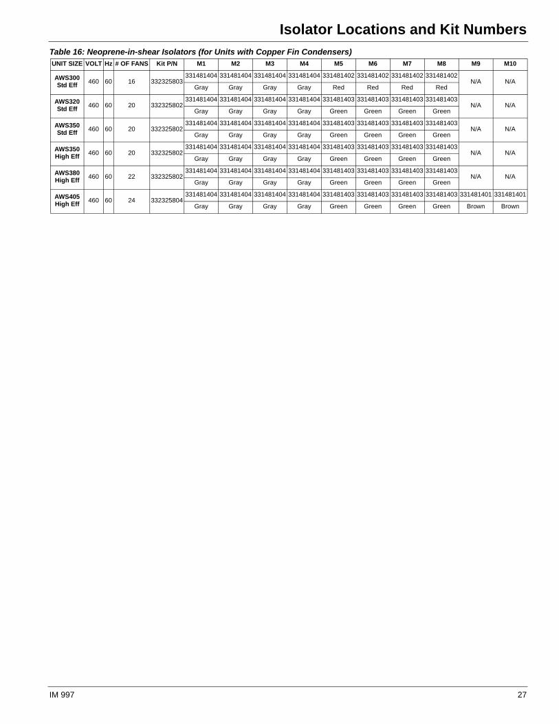
Table 16: Neoprene-in-shear Isolators (for Units with Copper Fin Condensers)UNIT SIZE VOLT Hz # OF FANS Kit P/N M1 M2 M3 M4 M5 M6 M7 M8 M9 M10
AWS300Std Eff
460 60 16 332325803331481404 331481404 331481404 331481404 331481402 331481402 331481402 331481402
N/A N/AGray Gray Gray Gray Red Red Red Red
AWS320Std Eff
460 60 20 332325802331481404 331481404 331481404 331481404 331481403 331481403 331481403 331481403
N/A N/AGray Gray Gray Gray Green Green Green Green
AWS350Std Eff
460 60 20 332325802331481404 331481404 331481404 331481404 331481403 331481403 331481403 331481403
N/A N/AGray Gray Gray Gray Green Green Green Green
AWS350High Eff
460 60 20 332325802331481404 331481404 331481404 331481404 331481403 331481403 331481403 331481403
N/A N/AGray Gray Gray Gray Green Green Green Green
AWS380High Eff
460 60 22 332325802331481404 331481404 331481404 331481404 331481403 331481403 331481403 331481403
N/A N/AGray Gray Gray Gray Green Green Green Green
AWS405High Eff
460 60 24 332325804331481404 331481404 331481404 331481404 331481403 331481403 331481403 331481403 331481401 331481401
Gray Gray Gray Gray Green Green Green Green Brown Brown
IM 997 27

Electrical Data
Electrical DataField WiringWiring must comply with all applicable codes and ordinances. Warranty does not cover damage to the equipment caused by wiring not complying with specifications.
An open fuse indicates a short, ground, or overload. Before replacing a fuse or restarting a compressor or fan motor, the trouble must be found and corrected.
Copper wire is required for all power lead terminations at the unit, and copper must be used for all other wiring to the unit.
Pathfinder chillers can be ordered with main power wiring for either multi-point power connection (standard) or single-point connection (optional).
If the optional single-point power connection is ordered, a single power connection is made to a power block (or optional disconnect switch) in the unit power panel. A separate disconnect is required if the optional factory-mounted disconnect is not ordered. Factory-mounted isolation circuit breakers for each circuit are included as standard on all single-point connection options.
If the standard multiple-point power wiring is ordered, two power connections are required. They are made to factory-mounted disconnect switches in the power panel. See the dimension drawings beginning on page 15 for entry locations.
It can be desirable to have the unit evaporator heaters on a separate disconnect switch from the main unit power supply so that the unit power can be shut down without defeating the freeze protection provided by the evaporator heaters. See the field wiring diagram on page 32 for connection details.
The 120-volt control transformer is factory mounted and wired.
.
CAUTION
If a separate disconnect is used for the 120V supply to the unit, it must power the entire control circuit. It must be clearly marked so that it is not accidentally shut off during freezing temperatures, thereby de-energizing the evaporator heaters. Freeze damage to the evaporator could result. If the evaporator is drained for winter freeze protection, the heaters must be de-energized to prevent heater burnout.
CAUTION
Pathfinder unit compressors are single-direction rotation compressors and can be damaged if rotated in the wrong direction. For this reason, proper phasing of electrical power is important. Electrical phasing must be A, B, C for electrical phases 1, 2 and 3 (A=L1, B=L2, C=L3) for single or multiple point wiring arrangements. The solid-state starters contain phase reversal protection. DO NOT ALTER THE WIRING TO THE STARTERS.
28 IM 997
Electrical Data
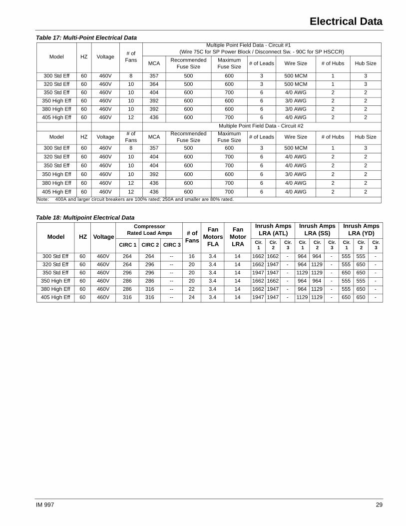
Table 17: Multi-Point Electrical Data
Model HZ Voltage# of
Fans
Multiple Point Field Data - Circuit #1 (Wire 75C for SP Power Block / Disconnect Sw. - 90C for SP HSCCR)
MCARecommended
Fuse SizeMaximum Fuse Size
# of Leads Wire Size # of Hubs Hub Size
300 Std Eff 60 460V 8 357 500 600 3 500 MCM 1 3
320 Std Eff 60 460V 10 364 500 600 3 500 MCM 1 3
350 Std Eff 60 460V 10 404 600 700 6 4/0 AWG 2 2
350 High Eff 60 460V 10 392 600 600 6 3/0 AWG 2 2
380 High Eff 60 460V 10 392 600 600 6 3/0 AWG 2 2
405 High Eff 60 460V 12 436 600 700 6 4/0 AWG 2 2
Multiple Point Field Data - Circuit #2
Model HZ Voltage# of
FansMCA
Recommended Fuse Size
Maximum Fuse Size
# of Leads Wire Size # of Hubs Hub Size
300 Std Eff 60 460V 8 357 500 600 3 500 MCM 1 3
320 Std Eff 60 460V 10 404 600 700 6 4/0 AWG 2 2
350 Std Eff 60 460V 10 404 600 700 6 4/0 AWG 2 2
350 High Eff 60 460V 10 392 600 600 6 3/0 AWG 2 2
380 High Eff 60 460V 12 436 600 700 6 4/0 AWG 2 2
405 High Eff 60 460V 12 436 600 700 6 4/0 AWG 2 2Note: 400A and larger circuit breakers are 100% rated; 250A and smaller are 80% rated.
Table 18: Multipoint Electrical Data
Model HZ Voltage
CompressorRated Load Amps # of
Fans
Fan Motors
FLA
Fan Motor LRA
Inrush AmpsLRA (ATL)
Inrush Amps LRA (SS)
Inrush AmpsLRA (YD)
CIRC 1 CIRC 2 CIRC 3 Cir. 1
Cir. 2
Cir. 3
Cir. 1
Cir. 2
Cir. 3
Cir. 1
Cir. 2
Cir. 3
300 Std Eff 60 460V 264 264 -- 16 3.4 14 1662 1662 - 964 964 - 555 555 -
320 Std Eff 60 460V 264 296 -- 20 3.4 14 1662 1947 - 964 1129 - 555 650 -
350 Std Eff 60 460V 296 296 -- 20 3.4 14 1947 1947 - 1129 1129 - 650 650 -
350 High Eff 60 460V 286 286 -- 20 3.4 14 1662 1662 - 964 964 - 555 555 -
380 High Eff 60 460V 286 316 -- 22 3.4 14 1662 1947 - 964 1129 - 555 650 -
405 High Eff 60 460V 316 316 -- 24 3.4 14 1947 1947 - 1129 1129 - 650 650 -
IM 997 29
Electrical Data
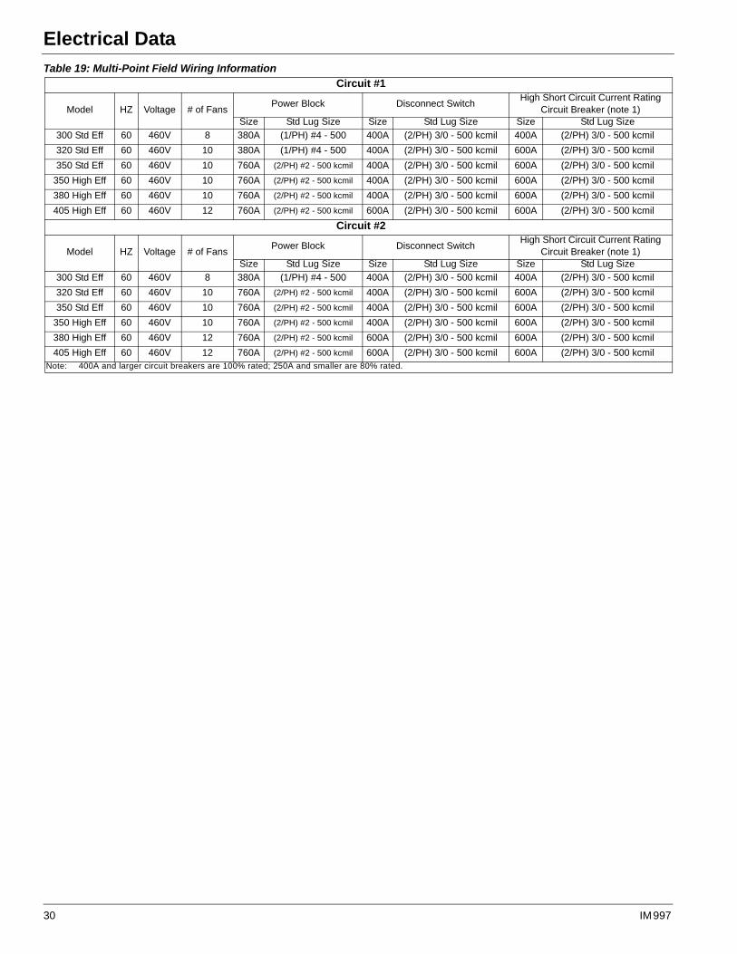
Table 19: Multi-Point Field Wiring Information Circuit #1
Model HZ Voltage # of FansPower Block Disconnect Switch
High Short Circuit Current Rating Circuit Breaker (note 1)
Size Std Lug Size Size Std Lug Size Size Std Lug Size
300 Std Eff 60 460V 8 380A (1/PH) #4 - 500 400A (2/PH) 3/0 - 500 kcmil 400A (2/PH) 3/0 - 500 kcmil
320 Std Eff 60 460V 10 380A (1/PH) #4 - 500 400A (2/PH) 3/0 - 500 kcmil 600A (2/PH) 3/0 - 500 kcmil
350 Std Eff 60 460V 10 760A (2/PH) #2 - 500 kcmil 400A (2/PH) 3/0 - 500 kcmil 600A (2/PH) 3/0 - 500 kcmil
350 High Eff 60 460V 10 760A (2/PH) #2 - 500 kcmil 400A (2/PH) 3/0 - 500 kcmil 600A (2/PH) 3/0 - 500 kcmil
380 High Eff 60 460V 10 760A (2/PH) #2 - 500 kcmil 400A (2/PH) 3/0 - 500 kcmil 600A (2/PH) 3/0 - 500 kcmil
405 High Eff 60 460V 12 760A (2/PH) #2 - 500 kcmil 600A (2/PH) 3/0 - 500 kcmil 600A (2/PH) 3/0 - 500 kcmil
Circuit #2
Model HZ Voltage # of FansPower Block Disconnect Switch
High Short Circuit Current Rating Circuit Breaker (note 1)
Size Std Lug Size Size Std Lug Size Size Std Lug Size
300 Std Eff 60 460V 8 380A (1/PH) #4 - 500 400A (2/PH) 3/0 - 500 kcmil 400A (2/PH) 3/0 - 500 kcmil
320 Std Eff 60 460V 10 760A (2/PH) #2 - 500 kcmil 400A (2/PH) 3/0 - 500 kcmil 600A (2/PH) 3/0 - 500 kcmil
350 Std Eff 60 460V 10 760A (2/PH) #2 - 500 kcmil 400A (2/PH) 3/0 - 500 kcmil 600A (2/PH) 3/0 - 500 kcmil
350 High Eff 60 460V 10 760A (2/PH) #2 - 500 kcmil 400A (2/PH) 3/0 - 500 kcmil 600A (2/PH) 3/0 - 500 kcmil
380 High Eff 60 460V 12 760A (2/PH) #2 - 500 kcmil 600A (2/PH) 3/0 - 500 kcmil 600A (2/PH) 3/0 - 500 kcmil
405 High Eff 60 460V 12 760A (2/PH) #2 - 500 kcmil 600A (2/PH) 3/0 - 500 kcmil 600A (2/PH) 3/0 - 500 kcmilNote: 400A and larger circuit breakers are 100% rated; 250A and smaller are 80% rated.
30 IM 997
Electrical Data
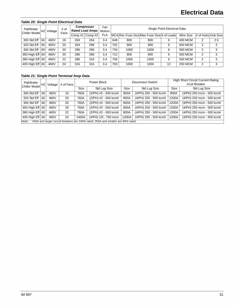
Table 20: Single Point Electrical Data
Pathfinder Chiller Model
HZ Voltage# of
Fans
CompressorRated Load Amps
Fan Motors
FLA
Single Point Electrical Data
Comp #1 Comp #2 MCA Rec Fuse Size Max Fuse Size # of Leads Wire Size # of Hubs Hub Size
300 Std Eff 60 460V 16 264 264 3.4 648 800 800 6 400 MCM 2 2.5
320 Std Eff 60 460V 20 264 296 3.4 702 800 800 6 500 MCM 2 3
350 Std Eff 60 460V 20 296 296 3.4 734 1000 1000 6 500 MCM 2 3
350 High Eff 60 460V 20 286 286 3.4 712 800 800 6 500 MCM 2 3
380 High Eff 60 460V 22 286 316 3.4 756 1000 1000 6 500 MCM 2 3
405 High Eff 60 460V 24 316 316 3.4 793 1000 1000 12 250 MCM 2 3
Table 21: Single Point Terminal Amp Data
PathfinderChiller Model
HZ Voltage # of FansPower Block Disconnect Switch
High Short Circuit Current Ratingircuit Breaker
Size Std Lug Size Size Std Lug Size Size Std Lug Size
300 Std Eff 60 460V 16 760A (2/PH) #2 - 500 kcmil 800A (4/PH) 250 - 500 kcmil 800A (4/PH) 250 mcm - 500 kcmil
320 Std Eff 60 460V 20 760A (2/PH) #2 - 500 kcmil 800A (4/PH) 250 - 500 kcmil 1200A (4/PH) 250 mcm - 500 kcmil
350 Std Eff 60 460V 20 760A (2/PH) #2 - 500 kcmil 800A (4/PH) 250 - 500 kcmil 1200A (4/PH) 250 mcm - 500 kcmil
350 High Eff 60 460V 20 760A (2/PH) #2 - 500 kcmil 800A (4/PH) 250 - 500 kcmil 1200A (4/PH) 250 mcm - 500 kcmil
380 High Eff 60 460V 22 760A (2/PH) #2 - 500 kcmil 800A (4/PH) 250 - 500 kcmil 1200A (4/PH) 250 mcm - 500 kcmil
405 High Eff 60 460V 24 1400A (4/PH) 1/0 - 750 mcm 1200A (4/PH) 250 - 500 kcmil 1200A (4/PH) 250 mcm - 500 kcmilNote: 400A and larger circuit breakers are 100% rated; 250A and smaller are 80% rated.
IM 997 31
Wiring Diagram
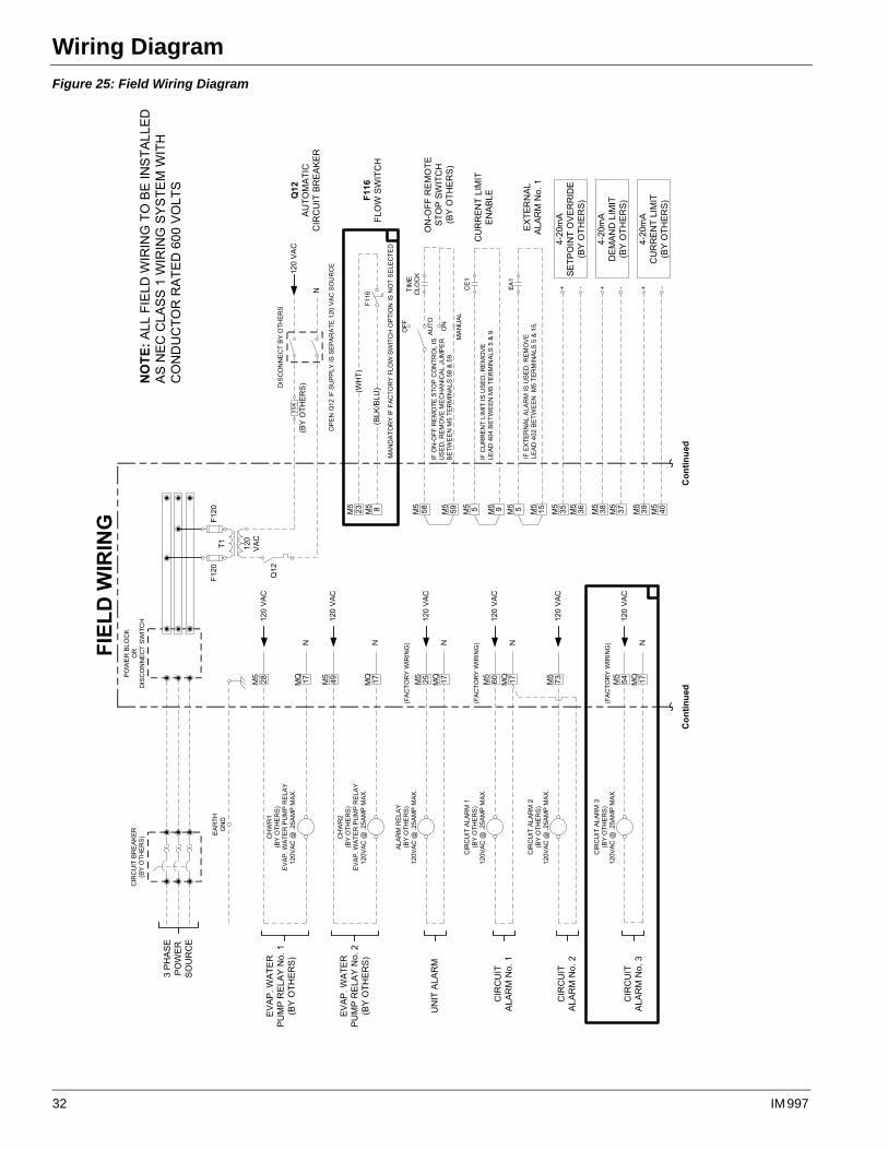
Wiring DiagramFigure 25: Field Wiring Diagram
������������
�� �������
�����
����
�����
����������
��
����������������
����
����
���
����
��
���
���
�������
�� ���� ��!���
�� �������
�����
�� �������
���������� ����
������"���# �� $�
#
�
�������
�� ���� ��!���
�� �������
#
�
�������
�� ��!���
#
�
�������
�� ��!���
#
�������
�� ��!���
#
�
����������
�� �������
������
�
���������������� ���������������������
����������� ������
�#
�����
���%
�� #
����&����
' #
����� ��������� ��������������������������������
##' ##(
���
���
��
���
��
�����
��)����� ���
�����������
�� �������
�����)����� �������������������
���*�� ��� �������+� ���
����� #��� �����#'�,�#(�
��������� ��
���
$����
�� ��!���
# ( #
#
��
������������ ���������*�� ��
���-�-������ #��� �����#�,�(�
�
���$������� �������*�� ���
���-��������� #��� �����#�,��#�
. )
#
# # �# #
#�# �%
-)��/
��������������
�� �������
� �
��� ���
������������
� �
�����������
���������
���������
. ) #
#�' �0
-)��/
� ����� ��
�� �������
�' �0 -( �0 %� �0 0� #- �0
��
. ) #
#�( -�
-)��/
��������� ��
�� �������
������
�
������
� �
������
������
������
�
���������������������������������
�������������������� �� ������
��������������%��������
�������
#
�
�� ���
�� �������
������"���# �� $�
�# �0
������
�
���������� ��
�� �������
������"���# �� $�
���������� ��
�� �������
������"���# �� $�
���������� ��
�� �������
������"���# �� $�
������ ��������
������ ��������
������ ��������
�����
�� �������
���������� ����
������"���# �� $�
32 IM 997
Wiring Diagram
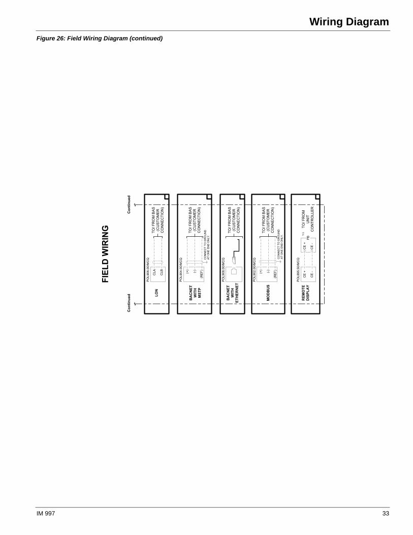
Figure 26: Field Wiring Diagram (continued)
����������
� �������
� �������
����������
� ����
����
���� �����
�
�
����������� �
��
����������
� ����
����
���� �����
���
���
����������� �
������
�����
����
�����
����������
� ����
����
���� �����
����������� �
�����
����
������
����
����
��������
������������� �
����������
� ����
����
���� �����
���
���
�����!����� �
������
�����
���� ����
��������
������������� �
���������
�����
����
�����
�����"�"��� �
������
�������
����
���
���
���
�#$
�
IM 997 33

Wiring Diagram
34 IM 997
Troubleshooting Chart
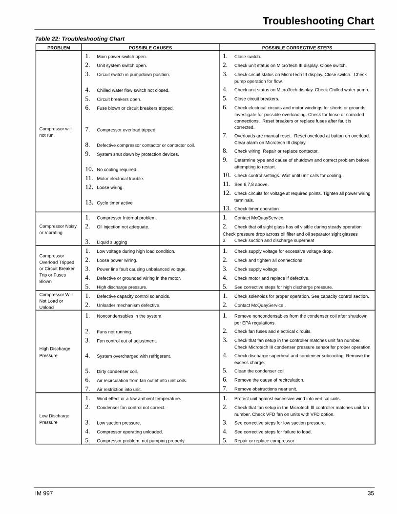
Troubleshooting ChartTable 22: Troubleshooting Chart
PROBLEM POSSIBLE CAUSES POSSIBLE CORRECTIVE STEPS
Compressor will
not run.
1. Main power switch open.
2. Unit system switch open.
3. Circuit switch in pumpdown position.
4. Chilled water flow switch not closed.
5. Circuit breakers open.
6. Fuse blown or circuit breakers tripped.
7. Compressor overload tripped.
8. Defective compressor contactor or contactor coil.
9. System shut down by protection devices.
10. No cooling required.
11. Motor electrical trouble.
12. Loose wiring.
13. Cycle timer active
1. Close switch.
2. Check unit status on MicroTech III display. Close switch.
3. Check circuit status on MicroTech III display. Close switch. Check
pump operation for flow.
4. Check unit status on MicroTech display. Check Chilled water pump.
5. Close circuit breakers.
6. Check electrical circuits and motor windings for shorts or grounds.
Investigate for possible overloading. Check for loose or corroded
connections. Reset breakers or replace fuses after fault is
corrected.
7. Overloads are manual reset. Reset overload at button on overload.
Clear alarm on Microtech III display.
8. Check wiring. Repair or replace contactor.
9. Determine type and cause of shutdown and correct problem before
attempting to restart.
10. Check control settings. Wait until unit calls for cooling.
11. See 6,7,8 above.
12. Check circuits for voltage at required points. Tighten all power wiring
terminals.
13. Check timer operation
Compressor Noisy
or Vibrating
1. Compressor Internal problem.
2. Oil injection not adequate.
3. Liquid slugging
1. Contact McQuayService.
2. Check that oil sight glass has oil visible during steady operation
Check pressure drop across oil filter and oil separator sight glasses3. Check suction and discharge superheat
Compressor
Overload Tripped
or Circuit Breaker
Trip or Fuses
Blown
1. Low voltage during high load condition.
2. Loose power wiring.
3. Power line fault causing unbalanced voltage.
4. Defective or grounded wiring in the motor.
5. High discharge pressure.
1. Check supply voltage for excessive voltage drop.
2. Check and tighten all connections.
3. Check supply voltage.
4. Check motor and replace if defective.
5. See corrective steps for high discharge pressure.
Compressor Will
Not Load or
Unload
1. Defective capacity control solenoids.
2. Unloader mechanism defective.
1. Check solenoids for proper operation. See capacity control section.
2. Contact McQuayService .
High Discharge
Pressure
1. Noncondensables in the system.
2. Fans not running.
3. Fan control out of adjustment.
4. System overcharged with refrigerant.
5. Dirty condenser coil.
6. Air recirculation from fan outlet into unit coils.
7. Air restriction into unit.
1. Remove noncondensables from the condenser coil after shutdown
per EPA regulations.
2. Check fan fuses and electrical circuits.
3. Check that fan setup in the controller matches unit fan number.
Check Microtech III condenser pressure sensor for proper operation.
4. Check discharge superheat and condenser subcooling. Remove the
excess charge.
5. Clean the condenser coil.
6. Remove the cause of recirculation.
7. Remove obstructions near unit.
Low Discharge
Pressure
1. Wind effect or a low ambient temperature.
2. Condenser fan control not correct.
3. Low suction pressure.
4. Compressor operating unloaded.
5. Compressor problem, not pumping properly
1. Protect unit against excessive wind into vertical coils.
2. Check that fan setup in the Microtech III controller matches unit fan
number. Check VFD fan on units with VFD option.
3. See corrective steps for low suction pressure.
4. See corrective steps for failure to load.
5. Repair or replace compressor
IM 997 35
Troubleshooting Chart
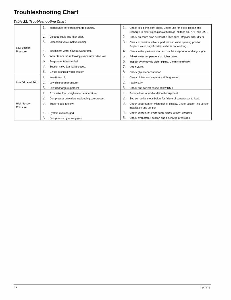
Low Suction
Pressure
1. Inadequate refrigerant charge quantity.
2. Clogged liquid line filter-drier.
3. Expansion valve malfunctioning.
4. Insufficient water flow to evaporator.
5. Water temperature leaving evaporator is too low.
6. Evaporator tubes fouled.
7. Suction valve (partially) closed.
8. Glycol in chilled water system
1. Check liquid line sight glass. Check unit for leaks. Repair and
recharge to clear sight glass at full load, all fans on, 75F min OAT..
2. Check pressure drop across the filter-drier. Replace filter-driers.
3. Check expansion valve superheat and valve opening position.
Replace valve only if certain valve is not working.
4. Check water pressure drop across the evaporator and adjust gpm.
5. Adjust water temperature to higher value.
6. Inspect by removing water piping. Clean chemically.
7. Open valve.
8. Check glycol concentration
Low Oil Level Trip
1. Insufficient oil.
2. Low discharge pressure.
3. Low discharge superheat
1. Check oil line and separator sight glasses.
2. Faulty EXV.
3. Check and correct cause of low DSH
High Suction
Pressure
1. Excessive load - high water temperature.
2. Compressor unloaders not loading compressor.
3. Superheat is too low.
4. System overcharged
5. Compressor bypassing gas
1. Reduce load or add additional equipment.
2. See corrective steps below for failure of compressor to load.
3. Check superheat on Microtech III display. Check suction line sensor
installation and sensor.
4. Check charge, an overcharge raises suction pressure
5. Check evaporator, suction and discharge pressures
Table 22: Troubleshooting Chart
36 IM 997


© 2009 McQuay International • www.mcquay.com • 800-432-1342 06/09
McQuay Training and Development
Now that you have made an investment in modern, efficient McQuay equipment, its care should be a high priority. For training information on all McQuay HVAC products, please visit us at www.mcquay.com and click on training, or call 540-248-9646 and ask for the Training Department.
Warranty
All McQuay equipment is sold pursuant to its standard terms and conditions of sale, including Limited Product Warranty. Consult your local McQuay Representative for warranty details. To find your local McQuay Representative, go to www.mcquay.com.
This document contains the most current product information as of this printing. For the most up-to-date product information, please go to www.mcquay.com.