Embed Size (px)
Citation preview

C-CL1-3-C9115-B INA-1308 Printed in Japan (MDOC) 2013
Revised publication effective Aug.2013.Superseding publication of C-CL1-3-C9115-A Mar.2013.
Specifications are subject to change without notice.
PASSENGER ELEVATOR(COMPACT MACHINE ROOM SYSTEM)Series-IP/AP Version2Series-IP
Eco Changes is the Mitsubishi Electric Group’s environmental statement,and expresses the Group’s stance on environmental management. Through a wide range of businesses, we are helping contribute to the realization of a sustainable society.
Visit our website at:http://www.mitsubishielectric.com/elevator/

Based on our policy, “Quality in Motion”,
we provide elevators and escalators that will
satisfy our customers with high levels of
comfort, efficiency, ecology and safety.
Principle
We strive to be green in all of our business activities.We take every action to reduce environmental burden during each process of our elevators’ and escalators’ lifecycle.
1 2
Contents
Variable Traveling Speed Elevator System
Group Control
5–6
9–10
Compact Machine Room
Green Technology 3–4
Efficiently using resources and minimizing environmental burden through leading-edge technologies.
An elevator that travels faster according to the number of passengers, reducing waiting and traveling time.
The machine room area is the same as that of a hoistway, maximizing available space in the building.
Advanced group control systems enhance transport efficiency and reduce passenger waiting time through optimum car allocation.
7–8
Our
Glo
bal S
tand
ards
for
Com
pact
Mac
hine
Roo
m E
leva
tors
Application
450 630 750 900 1050 1200 1350 1600 1800 2025 2250 2500 (kg)
0.75
1.0
1.6
1.75
2.0
2.5
3.0
3.5
(m/sec)
Note: The applicable range of the rated capacity may differ depending on the manufacturing factory, please consult our local agents for details.
Standard Design 11
Features 12–14
Basic Specifications 15–20
Important Information on Elevator Planning 21–22

SUSTAINABLE ENERGY USE
Efficient use of powerElevators usually travel using power from a power supply (powered operation); however, when they travel down with a heavy car load or up with a light car load (regenerative operation), the traction machine functions as a power generator. Although the power generated during traction machine operation is usually dissipated as heat, the Regenerative Converter transmits the power back to the distribution transformer and feeds it into the electrical
network in the building along with electricity from the power supply. Compared to the same type of elevator without a regenerative converter, this system provides an energy-saving effect of up to 35%. (Reduction in CO2 emissions: 1400 kg/year)In addition, the regenerative converter has the effect of decreasing harmonic currents.
Mitsubishi Electric’s leading-edge technologies have made it possible for elevators to conserve energy. Our Regenerative Converter makes the most of power generated by the traction machine. Additionally, thanks to the joint-lapped core in permanent magnet (PM) motor and energy-saving features, the elevators use energy more wisely and efficiently.
Curbing energy consumptionMitsubishi Electric offers features that help to reduce the energy consumption of elevators.
Energy-saving Operation– Number of Cars (ESO-N) (Optional for ΣAI-22)The number of service cars is automatically reduced tosome extent without affecting passenger waiting time. Energy-saving Operation– Allocation Control (ESO-W) (ΣAI-2200C only)Based on each elevator’s potential energy consumption, the system selects the elevator that best balances operational efficiency and energy consumption. Car Light/Fan Shut Off– Automatic (CLO-A/CFO-A)The car lighting/ventilation fan is automatically turnedoff if there are no calls for a specified period.
Smaller carbon footprintThe joint-lapped core built in the PM motor of the traction machine features flexible joints. The iron core can be like a hinge, which allows coils to be wound around the core more densely, resulting in improved motor efficiency and compactness. High-density magnetic field is produced, enabling lower use of energy and resources and reduced CO2 emissions.
Powered operation Regenerative operation
Motor
Control panel & regenerative converter
Motor
Control panel & regenerative converter
Distribution transformerPower supply
Distribution transformerPower supply
3 4
Regenerative Converter (Optional)Joint-lapped Core in PermanentMagnet (PM) Motor Energy-saving Features
Green Technology
Variable Traveling Speed Elevator System (VSE) (Optional)*
5 6
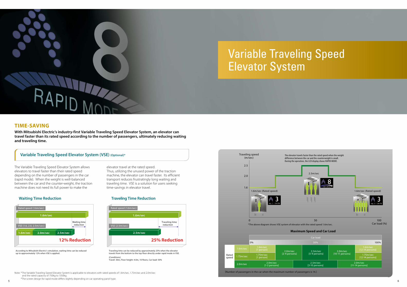
TIME-SAVINGWith Mitsubishi Electric’s industry-first Variable Traveling Speed Elevator System, an elevator can travel faster than its rated speed according to the number of passengers, ultimately reducing waiting and traveling time.
Note: *The Variable Traveling Speed Elevator System is applicable to elevators with rated speeds of 1.6m/sec, 1.75m/sec and 2.0m/sec and the rated capacity of 750kg to 1350kg. *The screen design for rapid mode differs slightly depending on car operating panel type.
The Variable Traveling Speed Elevator System allows elevators to travel faster than their rated speed depending on the number of passengers in the car (rapid mode). When the weight is well-balanced between the car and the counter-weight, the traction machine does not need its full power to make the
elevator travel at the rated speed. Thus, utilizing the unused power of the traction machine, the elevator can travel faster. Its efficient transport reduces frustratingly long waiting and traveling time. VSE is a solution for users seeking time-savings in elevator travel.
Car load
Ratedspeed
0% 50% 100%
1.6m/sec
1.75m/sec
2.0m/sec
1.6m/sec[1 person]
1.75m/sec[1 person]
1.6m/sec[12-14 persons]
1.75m/sec[12-14 persons]
2.0m/sec[2-4 persons]
2.5m/sec[5-9 persons]
2.0m/sec[10-11 persons]
2.0m/sec[1-2 persons]
2.5m/sec[3-10 persons]
2.0m/sec[11-14 persons]
Maximum Speed and Car Load
[Number of passengers in the car when the maximum number of passengers is 14.]
*The above diagram shows VSE system of elevator with the rated speed 1.6m/sec.
Traveling speed(m/sec)
The elevator travels faster than the rated speed when the weightdifference between the car and the counterweight is small.During the operation, the LCD display shows RAPID MODE.
2.5
2.0
1.6
2.5m/sec
1.6m/sec (Rated speed) 1.6m/sec (Rated speed)
100 Car load (%)
0 50
Variable Traveling SpeedElevator System
1.6m/sec
According to Mitsubishi Electric’s simulation, waiting time can be reduced up to approximately 12% when VSE is applied.
Waiting Time Reduction
2.0m/sec 2.5m/sec
VSE (1.6, 2.0, 2.5m/sec)
Rated speed (1.6m/sec)
12% Reduction
Waiting timereduction
1.6m/sec
Traveling time can be reduced by approximately 25% when the elevatortravels from the bottom to the top floor directly under rapid mode in VSE. (Conditions)Travel: 36m, Floor height: 4.0m, 10 floors, Car load: 50%
Traveling Time Reduction
25% Reduction
Rated speed (1.6m/sec)
VSE (2.5m/sec) Traveling time
reduction
1.6m/sec
2.5m/sec

Compact PM Gearless Traction Machine Compact Control Panel
7 8
SPACE-SAVINGThrough the development of the Compact Gearless Traction Machine and Compact Control Panel, Mitsubishi Electric has successfully reduced the machine room area to that of hoistway*1, where the machine room used to require an area twice as large as that of hoistway. It offers the most advanced elevator features without requiring a large machine room, thus maximizing the use of building space.
The control panel that drives the PM motor has also been reduced in size. Incorporating the most advanced, low-loss IGBT (Insulated Gate Bipolar Transistor) into an optimal design, the power unit has decreased in size significantly, making the control panel itself smaller than previous models. The functions and performance of this Compact Control Panel remain unchanged.
The VVVF Inverter Control delivers smooth, high-precision control of the traction machine. A combina-tion of these state-of-the-art components contributes to significant power savings, while achieving the desired functions and performance of the control panel.
Mitsubishi Electric was the first company to replaceinduction motors with its highly sophisticated PM (permanent magnet) motors for high-speed and super high-speed elevators. The extremely thin PM motor manufactured using Mitsubishi Electric’s unique stator core technology –Joint-lapped Core* in Permanent Magnet (PM) Motor– has dramatically reduced not only the size of traction machines but also energy consumption. Furthermore, the PM motor suppresses harmonic noise and torque ripple, providing greater riding comfort.
Notes:*1: The area of the machine room may have to be
larger than that of the hoistway in case of (a), (b) and/or (c) below.
(a) An optional feature that requires a panel(s), in addition to the control panel, is requested.
(b) The car interior width (AA) is less than 1600mm, and the entrance width (JJ) is less than 900mm for 2-panel center opening (CO) or 1100mm for 2-panel side opening (2S).
(c) The counterweight is installed in a side drop position.
*2: The area of the machine room can be reduced approximately 9m2 when the rated capacity is
1050kg and the rated speed is 1.75m/sec. The area may differ depending on the conditions.
Compact Machine RoomConventional Machine Room
NexWay-S
-9m2 *2
GPS-III
Example of Space-saving
Machine room area: 13m2 Machine room area: 4m2
Compact Control Panel
Compact PM Gearless Traction Machine
Note: *Please refer to page 4 for details.
Compact Machine Room

Dynamic Rule-set Optimizer
9 10
EFFICIENT TRANSPORTATIONMitsubishi Electric’s breakthrough AI Neural Network* technology in elevator control enhances transport efficiency and reduces passenger waiting time through optimum car allocation, which allows elevators to use energy effectively. Two basic group control systems offer a variety of innovative group control features.Note: *Neural Network is a mathematical model that emulates the structure of the nerves and cells of the human brain and its information processing mechanism.
DOAS-S (Lobby floor(s))DOAS-S hall operating panels are installed only on busy floor(s) such as the lobby while other floors have conventional hall fixtures. This is particularly beneficial for improving the traffic flow leaving from the busy floor. It is especially useful in buildings with heavy up-peak traffic.
DOAS-S (All floors)DOAS-S hall operating panels are installed on all floors. Cars receive destination information from all floors to provide the best service for more complex traffic conditions throughout the day.
Example of hall arrangement Example of hall arrangement
The features introduced on these pages are applicable to ΣAI-2200C only. Please refer to page 13 and 14, and the ΣAI-2200C brochure for other features and details.
Group controlsystems
ΣAI-22 system
ΣAI-2200C system
Suitable building size
Small to medium
Large(Especially buildingswith dynamic traffic
conditions)
Number of carsin a group
3 to 4 cars
3 to 8 carsSelects optimum car allocation through rule-set simulationsBased on real traffic data, passenger traffic is predicted every few minutes. According to the prediction, real-time simulation selects the best rule-set (multiple rules have been set as car allocation patterns), which optimizes transport efficiency.
Allocates passengers to cars depending on destination floorsWhen a passenger enters a destination floor at a hall, the hall operating panel immediately indicates which car will serve the floor. Because the destination floor is already registered, the passenger does not need to press a button in the car. Further-more, dispersing passengers by destination prevents congestion in cars and minimizes their waiting and traveling time.Forecasts a near-future hall call to reduce long waits
When a hall call is registered, the algorithm assumes near-future calls that could require long waits. Through evaluation of the registered hall call and the forecasted call, the best car is assigned. All cars work cooperatively for optimum operation.
Destination Oriented Prediction System (DOAS-S) (Optional)
Performance
0
5
10
15
20
25
30
Morning uppeak
Lunchtime Eveningdown peak
Daytime0
2
4
6
8
10
Morning uppeak
Lunchtime Eveningdown peak
Daytime
Average waiting time Long-wait rate (60 seconds or longer) (sec) (%)
AI-2100N (Conventional system)
AI-2200C
Cooperative Optimization Assignment
Please consult our local agents for DOAS-S (all floors).
All floors
Other floors
Lobby
Group Control
AI-2100N (Conventional system)[A hall call is registered at 6th Fl.]Allocates the closest car B.[Another hall call is soon registered at 11th Fl.]Allocates D, resulting in long wait of 26 sec.
ΣAI-2200C (New)[A hall call is registered at 6th Fl.]Allocates D, which is moving upward.[Another hall call is soon registered at 11th Fl.]Allocates B, which immediately arrives at the floor.
Ele. No.
Hall call Traveling directionCar callCar
Ele. No.
1211
Notes:*1: Maximum number of floors: 22 floors*2: Some letters of the alphabets are not available. Please consult our local agents for details.
Actual colors may differ slightly from those shown.Please refer to the design guide for details and other designs.
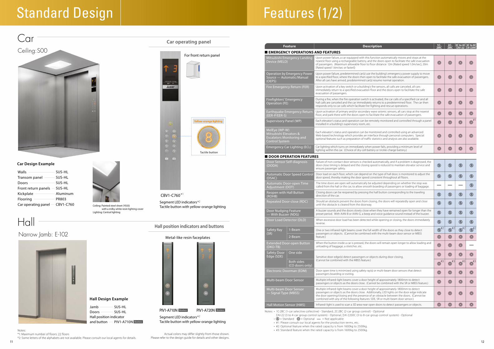
SUS-HLSUS-HLSUS-HLSUS-HLAluminumPR803CBV1-C760 Ceiling: Painted steel sheet (Y033)
with a milky white resin lighting coverLighting: Central lighting
WallsTransom panelDoorsFront return panelsKickplateFlooringCar operating panel
Car Design Example
Hall Design Example
Car
Hall
Segment LED indicatorsTactile button with yellow-orange lighting
Car operating panel
Hall position indicators and buttons
*2
JambDoorsHall position indicatorand button
SUS-HLSUS-HL
PIV1-A710N
Narrow Jamb: E-102
Ceiling: S00
Boxless
PIV1-A710N PIV1-A720N
Metal-like resin faceplates
Features (1/2)
CBV1-C760*1
*2Segment LED indicatorsTactile button with yellow-orange lighting
For front return panel
Yellow-orange lighting
Tactile button
Boxless Boxless
Feature Description 3C to 8CΣAI-2200C
3C to 4CΣAI-22
1C-2BC
2C-2BC
■ EMERGENCY OPERATIONS AND FEATURESUpon power failure, a car equipped with this function automatically moves and stops at the nearest floor using a rechargeable battery, and the doors open to facilitate the safe evacuation of passengers. (Maximum allowable floor to floor distance: 12m [Rated speed 1.0m/sec], 20m [Rated speed 1.6m/sec or faster])
Mitsubishi Emergency LandingDevice (MELD)
Upon power failure, predetermined car(s) use the building’s emergency power supply to move to a specified floor, where the doors then open to facilitate the safe evacuation of passengers. After all cars have arrived, predetermined car(s) resume normal operation.
Operation by Emergency PowerSource — Automatic/Manual(OEPS)
Upon activation of a key switch or a building’s fire sensors, all calls are canceled, all cars immediately return to a specified evacuation floor and the doors open to facilitate the safe evacuation of passengers.
Fire Emergency Return (FER)
During a fire, when the fire operation switch is activated, the car calls of a specified car and all hall calls are canceled and the car immediately returns to a predetermined floor. The car then responds only to car calls which facilitate fire-fighting and rescue operations.
Firefighters’ EmergencyOperation (FE)
Upon activation of primary and/or secondary wave seismic sensors, all cars stop at the nearest floor, and park there with the doors open to facilitate the safe evacuation of passengers.
Earthquake Emergency Return(EER-P/EER-S)
Each elevator’s status and operation can be remotely monitored and controlled through a panel installed in a building’s supervisory room, etc.
Supervisory Panel (WP)
MelEye (WP-W)Mitsubishi Elevators & Escalators Monitoring and Control System
Each elevator’s status and operation can be monitored and controlled using an advanced Web-based technology which provides an interface through personal computers. Special optional features such as preparation of traffic statistics and analysis are also available.
Car lighting which turns on immediately when power fails, providing a minimum level of lighting within the car. (Choice of dry-cell battery or trickle-charge battery.)
Emergency Car Lighting (ECL)
#1
■ DOOR OPERATION FEATURESFailure of non-contact door sensors is checked automatically, and if a problem is diagnosed, the door-close timing is delayed and the closing speed is reduced to maintain elevator service and ensure passenger safety.
Door Sensor Self-diagnosis(DODA)
Door load on each floor, which can depend on the type of hall door, is monitored to adjust the door speed, thereby making the door speed consistent throughout all floors.
Automatic Door Speed Control(DSAC)
The time doors are open will automatically be adjusted depending on whether the stop was called from the hall or the car, to allow smooth boarding of passengers or loading of baggage.
Automatic Door-open TimeAdjustment (DOT)
Closing doors can be reopened by pressing the hall button corresponding to the traveling direction of the car.
Reopen with Hall Button(ROHB)
Should an obstacle prevent the doors from closing, the doors will repeatedly open and close until the obstacle is cleared from the doorway.
Repeated Door-close (RDC)
When the button inside a car is pressed, the doors will remain open longer to allow loading and unloading of baggage, a stretcher, etc.
Extended Door-open Button(DKO-TB)
When excessive door load has been detected while opening or closing, the doors immediately reverse.
Door Load Detector (DLD)
Safety Door Edge (SDE)
Safety Ray (SR)
1-Beam
2-Beam
Electronic Doorman (EDM) Door open time is minimized using safety ray(s) or multi-beam door sensors that detect passengers boarding or exiting.
Door Nudging Feature— With Buzzer (NDG)
A buzzer sounds and the doors slowly close when they have remained open for longer than the preset period. With AAN-B or AAN-G, a beep and voice guidance sound instead of the buzzer.
One side
Both sides(CO doors only)
Sensitive door edge(s) detect passengers or objects during door closing.(Cannot be combined with the MBSS feature.)
One or two infrared-light beams cover the full width of the doors as they close to detect passengers or objects. (Cannot be combined with the multi-beam door sensor or MBSS feature.)
Multi-beam Door Sensor Multiple infrared-light beams cover a door height of approximately 1800mm to detect passengers or objects as the doors close. (Cannot be combined with the SR or MBSS feature.)
Multi-beam Door Sensor— Signal Type (MBSS)
Multiple infrared-light beams cover a door height of approximately 1800mm to detect passengers or objects as the doors close. Additionally, LED lights on the door edge indicate the door opening/closing and the presence of an obstacle between the doors. (Cannot be combined with any of the following features: SDE, SR or multi-beam door sensor.)
Hall Motion Sensor (HMS) Infrared-light is used to scan a 3D area near open doors to detect passengers or objects.
Notes: • 1C-2BC (1-car selective collective) - Standard, 2C-2BC (2-car group control) - Optional ΣAI-22 (3 to 4-car group control system) - Optional, ΣAI-2200C (3 to 8-car group control system) - Optional • = Standard = Optional = Not applicable • #1: Please consult our local agents for the production terms, etc. • #2: Optional feature when the rated capacity is from 1600kg to 2500kg. • #3: Standard feature when the rated capacity is from 1600kg to 2500kg.
Standard Design
#2#2 #2 #2
#3#3 #3 #3

A click-type car button which emits an electronic beep sound when pressed to indicate that the call has been registered.
Sonic Car Button — ClickType (ACB)
Controls the number of cars to be allocated and the timing of car allocation in order to meet increased demand for downward travel during office leaving time, hotel check-out time, etc. to minimize passenger waiting time.
Down Peak Service (DPS)
Energy-saving Operation— Number of Cars (ESO-N)
To save energy, the number of service cars is automatically reduced to some extent, but not so much that it adversely affects passenger waiting time. Please refer to page 4.
Feature Description 3C to 8CΣAI-2200C
3C to 4CΣAI-22
1C-2BC
2C-2BC Feature Description 3C to 8C
ΣAI-2200C3C to 4CΣAI-22
1C-2BC
2C-2BC
1413
■ OPERATIONAL AND SERVICE FEATURES
Forced Floor Stop (FFS) All cars in a bank automatically make a stop at a predetermined floor on every trip without being called.
Main Floor Parking (MFP) An available car always parks on the main (lobby) floor with the doors open/closed (China only).
An operation by car controllers which automatically maintains elevator operation in the event that a microprocessor or transmission line in the group controller has failed.
With a key switch on the supervisory panel, etc., a car can be called to a specified floor after responding to all car calls, and then automatically be taken out of service.
Out-of-service-remote (RCS)
To enhance security, car calls for desired floors can be registered only by entering secret codes using the car buttons on the car operating panel. This function is automatically deactivated during emergency operation.
Secret Call Service (SCS-B)
To enhance security, car calls for desired floors can be registered only by placing a card over a card reader. This function is automatically deactivated during emergency operation.
Non-service TemporaryRelease for Car Call— Card Reader Type (NSCR-C)
To enhance security, service to specific floors can be disabled using the car operating panel. This function is automatically deactivated during emergency operation.
Non-service to Specific Floors— Car Button Type (NS-CB)
To enhance security, service to specific floors can be disabled using a manual or timer switch. This function is automatically deactivated during emergency operation.
Non-service to Specific Floors— Switch/Timer Type (NS/NS-T)
For maintenance or energy-saving measures, a car can be taken out of service temporarily with a key switch (with or without a timer) mounted in a specified hall.
Out-of-service by Hall KeySwitch (HOS/HOS-T)
Using a key switch on the supervisory panel, a car can be withdrawn from group control operation and called to a specified floor. The car will park on that floor with the doors open, and not accept any calls until independent operations begin.
Return Operation (RET)
Exclusive operation where an elevator can be operated using the buttons and switches located in the car operating panel, allowing smooth boarding of passengers or loading of baggage.
Attendant Service (AS)
According to the number of passengers in the car, the car travels faster than the rated speed. Please refer to page 5 and 6.
Variable Traveling SpeedElevator System (VSE)
For energy conservation, power regenerated by a traction machine can be used by other electrical systems in the building. Please refer to page 3.
Regenerative Converter(PCNV)
Exclusive operation where a car is withdrawn from group control operation for independent use, such as maintenance or repair, and responds only to car calls.
Independent Service (IND)
If a car has stopped between floors due to some equipment malfunction, the controller checks the cause, and if it is considered safe to move the car, the car will move to the nearest floor at a low speed and the doors will open.
Safe Landing (SFL)
If the elevator doors do not open fully at a destination floor, the doors close, and the car automatically moves to the next or nearest floor where the doors will open.
Next Landing (NXL)
A car which is experiencing trouble is automatically withdrawn from group control operation to maintain overall group performance.
Continuity of Service (COS)
A fully-loaded car bypasses hall calls in order to maintain maximum operational efficiency.Automatic Bypass (ABP)
Overload Holding Stop (OLH)
If one car cannot carry all waiting passengers because it is full, another car will automatically be assigned for the remaining passengers.
Automatic Hall Call Registration (FSAT)Car Call Canceling (CCC)
If there are no calls for a specified period, the car ventilation fan will automatically turn off to conserve energy. Please refer to page 4.
If there are no calls for a specified period, the car lighting will automatically turn off to conserve energy. Please refer to page 4.
If the number of registered car calls does not correspond to the car load, all calls are canceled to avoid unnecessary stops.
False Call Canceling — Automatic (FCC-A)
When a car has responded to the final car call in one direction, the system regards remaining calls in the other direction as mistakes and clears them from the memory.
A buzzer sounds to alert the passengers that the car is overloaded. The doors remain open and the car will not leave that floor until enough passengers exit the car.
Special Floor Priority Service(SFPS)
Special floors, such as floors with VIP rooms or executive rooms, are given higher priority for car allocation when a call is made on those floors. (Cannot be combined with hall position indicators.)
A function to give priority allocation to the car closest to the floor where a hall call button has been pressed, or to reverse the closing doors of the car closest to the pressed hall call button on that floor. (Cannot be combined with hall position indicators.)
Closest-car Priority Service(CNPS)
#1
#1
#1
Notes: • 1C-2BC (1-car selective collective) - Standard, 2C-2BC (2-car group control) - Optional ΣAI-22 (3 to 4-car group control system) - Optional, ΣAI-2200C (3 to 8-car group control system) - Optional • = Standard = Optional = Not applicable • #1: Please consult our local agents for the production terms, etc. • #2: When DOAS-S is applied, SR or multi-beam door sensor should be installed. • #3: Standard feature when the rated capacity is from 1600kg to 2500kg.
If the wrong car button is pressed, it can be canceled by quickly pressing the same button again twice.
False Call Canceling— Car Button Type (FCC-P)
Backup Operation for GroupControl Microprocessor (GCBK)
Car Fan Shut Off — Automatic (CFO-A)
Car Light Shut Off — Automatic (CLO-A)
Features (2/2)
■ GROUP CONTROL FEATURES
To maximize transport efficiency, an elevator bank is divided into two groups of cars to serve upper and lower floors separately during up peak. In addition, the number of cars to be allocated, the timing of car allocation to the lobby floor, the timing of door closing, etc. are controlled based on predicted traffic data.
Intense Up Peak (IUP)
Controls the number of cars to be allocated to the lobby floor, as well as the car allocation timing, in order to meet increased demand for upward travel from the lobby floor during office starting time, hotel check-in times, etc., and minimize passenger waiting time.
Up Peak Service (UPS)
When a passenger enters a destination floor at a hall, the hall operating panel indicates which car will serve the floor. The passenger does not need to press a button in the car. Dispersing passengers by destination prevents congestion in the cars and minimizes their waiting and traveling time. (Cannot be combined with some features. Please consult our local agents for details.) Please refer to page 10.
Destination Oriented Prediction System (DOAS-S) #2
#1#1#1#1
The timing of car allocation and the number of cars to be allocated to floors where meeting rooms or ballrooms exist and the traffic intensifies for short periods of time are controlled according to the detected traffic density data for those floors.
Congested-floor Service (CFS)
Hall buttons and the cars called by each button can be divided into several groups for independent group control operation to serve special needs or different floors.
Bank-separation Operation(BSO)
A specified car is withdrawn from group control operation for VIP service operation. When activated, the car responds only to existing car calls, moves to a specified floor and parks there with the doors open. The car will then respond only to car calls.
VIP Operation (VIP-S)
During the first half of lunchtime, calls for a restaurant floor are served with higher priority, and during the latter half, the number of cars allocated to the restaurant floor, the allocation timing for each car and the door opening and closing timing are all controlled based on predicted data.
Lunchtime Service (LTS)
This feature is effective for buildings with two main (lobby) floors. The floor designated as the “main floor” in a group control operation can be changed as necessary using a manual switch.
Main Floor ChangeoverOperation (TFS)
When traffic is light, empty or lightly-loaded cars are given higher priority to respond to hall calls in order to minimize passenger travel time. (Cannot be combined with hall position indicators.)
Light-load Car Priority Service(UCPS)
Special cars, such as observation elevators and elevators with basement service, are given higher priority to respond to hall calls. (Cannot be combined with hall position indicators.)
Special Car Priority Service(SCPS)
#1
#1
#1
#1
■ SIGNAL AND DISPLAY FEATURES
Electronic chimes sound to indicate that a car will soon arrive. (The chimes are mounted either on the top and bottom of the car, or in each hall.)
Car Arrival Chime Car (AECC)
Hall (AECH)
When a passenger has registered a hall call, the best car to respond to that call is immediately selected, the corresponding hall lantern lights up and a chime sounds once to indicate which doors will open.
Immediate Prediction Indication (AIL)
When a hall is crowded to the extent that one car cannot accommodate all waiting passengers, a hall lantern will light up to indicate the next car to serve the hall.
Second Car Prediction (TCP)
A synthetic voice (and/or buzzer) alerts passengers inside a car that elevator operation has been temporarily interrupted by overloading or a similar cause. (Voice available only in English.)
Basic Announcement (AAN-B)
Information on elevator service such as the current floor or service direction is given to the passengers inside a car. (Voice guidance available only in English.)
Voice Guidance System(AAN-G)
An additional car control panel which can be installed for large-capacity elevators, heavy-traffic elevators, etc.
Auxiliary Car Operating Panel(ACS)
A system which allows communication between passengers inside a car and the building personnel.
Inter-communication System(ITP)
A hall lantern, which corresponds to a car’s service direction, flashes to indicate that the car will soon arrive.
Flashing Hall Lantern (FHL)
This 5.7-inch LCD for car operating panels shows the date and time, car position, travel direction and elevator status messages.
Car LCD Position Indicator (CID-S)
This LCD (10.4- or 15-inch) for car front return panels shows the date and time, car position, travel direction and elevator status messages.
Car Information Display (CID)
This 5.7-inch LCD for elevator halls shows the date and time, car position, travel direction and elevator status messages.
Hall LCD Position Indicator(HID-S)
This LCD (10.4- or 15-inch) for elevator halls shows the date and time, car position, travel direction and elevator status messages.
Hall Information Display (HID)
#3#3#3
1615
Basic Specifications (750kg to 1350kg)G
B c
ode
EN81
-1
Ratedcapacity
(kg)
Number ofpersons
Codenumber
Doortype
Counter-weight
position
Car internaldimensions
(mm)AAxBB
Entrancewidth (mm)
JJ
Minimum hoistway dimensions (mm)AHxBH
Rated speed (m/sec)2.5
Travel (m) TR120<TR≤150
1950x18902160x1700 *1
2000x19402290x1740 *1
1790x25102400x19902690x1770 *2
1970x27102400x20902690x1870 *1
1950x18402140x1690 *1
1950x18902160x1700 *1
2000x18702290x1690 *1
2000x19402290x1740 *1
2200x18902490x1700 *1
2000x20402290x1840 *1
1790x25102200x20902490x1870 *1
2400x19402690x1740 *2
2400x19902690x1770 *2
1970x27102400x20902690x1870 *1
2200x22702490x2020 *3
1950x1890
2030x1990
2430x1990
2430x2090
1950x1840
1950x1890
2030x1870
2030x1990
2230x1940
2030x2090
2230x2090
2430x1940
2430x1990
2430x2090
2230x2270
900
1100
900
1000
900
1000
1100
1000
1400x1350
1600x1400
1100x2100
2000x1400
1200x2300
2000x1500
1400x1300
1400x1350
1600x1330
1600x1400
1800x1350
1600x1500
1100x2100
1800x1500
2000x1350
2000x1400
1200x2300
2000x1500
1800x1680
RearSideRear
Side
Rear
Side
RearSideRearSideRearSideRearSideRearSideRearSideRear
Side
RearSideRearSideRear
Side
RearSideRearSide
CO
2S
CO
2S
CO
CO
2S
CO
2S
CO
825
1050
1275
1350
750
825
900
1050
1200
1275
1350
11
14
17
18
10
11
12
14
16
17
18
P11
P14
P17
P18
P10
P11
P12
P14
P16
P17
P18
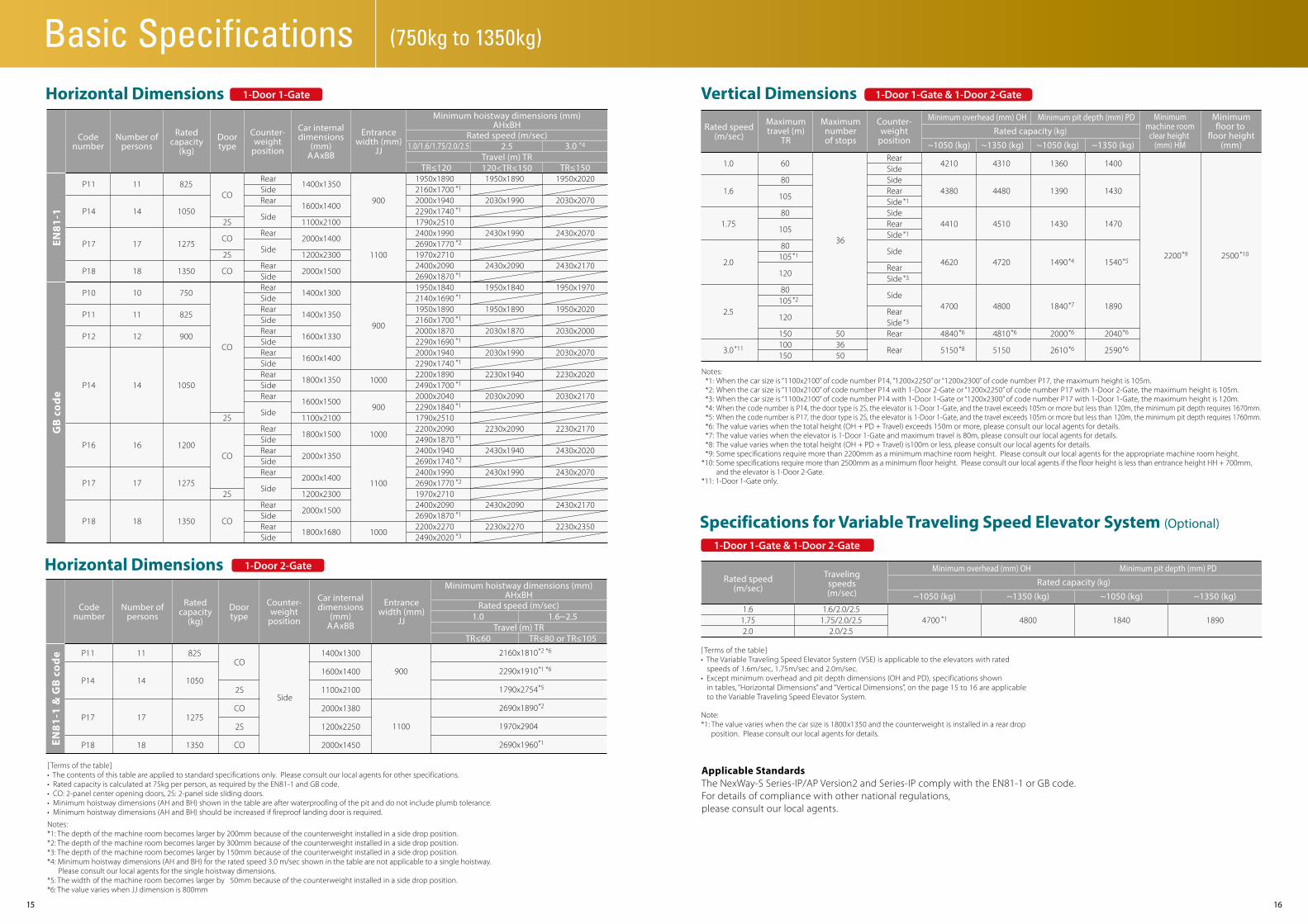
[ Terms of the table]• The contents of this table are applied to standard specifications only. Please consult our local agents for other specifications.• Rated capacity is calculated at 75kg per person, as required by the EN81-1 and GB code.• CO: 2-panel center opening doors, 2S: 2-panel side sliding doors.• Minimum hoistway dimensions (AH and BH) shown in the table are after waterproofing of the pit and do not include plumb tolerance.• Minimum hoistway dimensions (AH and BH) should be increased if fireproof landing door is required.
Notes: *1: The depth of the machine room becomes larger by 200mm because of the counterweight installed in a side drop position.*2: The depth of the machine room becomes larger by 300mm because of the counterweight installed in a side drop position.*3: The depth of the machine room becomes larger by 150mm because of the counterweight installed in a side drop position.*4: Minimum hoistway dimensions (AH and BH) for the rated speed 3.0 m/sec shown in the table are not applicable to a single hoistway. Please consult our local agents for the single hoistway dimensions.*5: The width of the machine room becomes larger by 50mm because of the counterweight installed in a side drop position.*6: The value varies when JJ dimension is 800mm
1.0/1.6/1.75/2.0/2.5 3.0 *4
TR≤120 TR≤1501950x2020
2030x2070
2430x2070
2430x2170
1950x1970
1950x2020
2030x2000
2030x2070
2230x2020
2030x2170
2230x2170
2430x2020
2430x2070
2430x2170
2230x2350
Horizontal Dimensions Rated speed
(m/sec)
Maximumtravel (m)
TR
Maximumnumberof stops
Minimummachine room
clear height (mm) HM
Minimumfloor to
floor height(mm)
Minimum overhead (mm) OH Minimum pit depth (mm) PDRated capacity (kg)
~1050 (kg) ~1350 (kg) ~1050 (kg) ~1350 (kg)
Counter-weight
position
RearSideSideRearSideSideRearSide
Side
RearSide
Side
RearSideRear
Rear
1.0
1.6
1.75
2.0
2.5
3.0
60
80
105
80
105
80105
120
80105
120
150100150
4210
4380
4410
4620
4700
4840
5150
1360
1390
1430
1490
1840
2000
2610
1400
1430
1470
1540
1890
2040
2590
36
503650
*1
*1
*1
*3
*3
*6
*11
*6 *6
*7
*6
*6
*4 *5
*6 *8
*2
4310
4480
4510
4720
4800
4810
5150
2200 *9 2500 *10
Notes: *1: When the car size is “1100x2100” of code number P14, “1200x2250” or “1200x2300” of code number P17, the maximum height is 105m. *2: When the car size is “1100x2100” of code number P14 with 1-Door 2-Gate or “1200x2250” of code number P17 with 1-Door 2-Gate, the maximum height is 105m. *3: When the car size is “1100x2100” of code number P14 with 1-Door 1-Gate or “1200x2300” of code number P17 with 1-Door 1-Gate, the maximum height is 120m. *4: When the code number is P14, the door type is 2S, the elevator is 1-Door 1-Gate, and the travel exceeds 105m or more but less than 120m, the minimum pit depth requires 1670mm. *5: When the code number is P17, the door type is 2S, the elevator is 1-Door 1-Gate, and the travel exceeds 105m or more but less than 120m, the minimum pit depth requires 1760mm. *6: The value varies when the total height (OH + PD + Travel) exceeds 150m or more, please consult our local agents for details. *7: The value varies when the elevator is 1-Door 1-Gate and maximum travel is 80m, please consult our local agents for details. *8: The value varies when the total height (OH + PD + Travel) is100m or less, please consult our local agents for details. *9: Some specifications require more than 2200mm as a minimum machine room height. Please consult our local agents for the appropriate machine room height.*10: Some specifications require more than 2500mm as a minimum floor height. Please consult our local agents if the floor height is less than entrance height HH + 700mm, and the elevator is 1-Door 2-Gate.*11: 1-Door 1-Gate only.
Vertical Dimensions 1-Door 1-Gate 1-Door 1-Gate & 1-Door 2-Gate
EN81
-1 &
GB
co
de
Ratedcapacity
(kg)
Number ofpersons
Codenumber
Doortype
Counter-weight
position
Car internaldimensions
(mm)AAxBB
Entrancewidth (mm)
JJ
Minimum hoistway dimensions (mm)AHxBH
Rated speed (m/sec)
Travel (m) TR
900
1100
1400x1300
1600x1400
1100x2100
2000x1380
1200x2250
2000x1450
825
1050
1275
1350
P11
P14
P17
P18
11
14
17
18
CO
2S
CO
2S
CO
2160x1810
2290x1910
1790x2754
2690x1890
1970x2904
2690x1960
Side
*2 *6
*1 *6
*5
*2
*1
1.0
TR≤60
1.6~2.5
TR≤80 or TR≤105
Horizontal Dimensions 1-Door 2-Gate
Note:*1: The value varies when the car size is 1800x1350 and the counterweight is installed in a rear drop position. Please consult our local agents for details.
Specifications for Variable Traveling Speed Elevator System (Optional)
Rated speed(m/sec)
Travelingspeeds(m/sec)
1.61.752.0
1.6/2.0/2.51.75/2.0/2.5
2.0/2.54700 *1 4800 1840 1890
Minimum overhead (mm) OH Minimum pit depth (mm) PDRated capacity (kg)
~1050 (kg) ~1350 (kg) ~1050 (kg) ~1350 (kg)
[ Terms of the table]• The Variable Traveling Speed Elevator System (VSE) is applicable to the elevators with rated speeds of 1.6m/sec, 1.75m/sec and 2.0m/sec.• Except minimum overhead and pit depth dimensions (OH and PD), specifications shown in tables, “Horizontal Dimensions” and “Vertical Dimensions”, on the page 15 to 16 are applicable to the Variable Traveling Speed Elevator System.
Applicable StandardsThe NexWay-S Series-IP/AP Version2 and Series-IP comply with the EN81-1 or GB code. For details of compliance with other national regulations, please consult our local agents.
1-Door 1-Gate & 1-Door 2-Gate

Hoistway Plan Hoistway Section
1817
Mac
hine
roo
mcl
ear
heig
ht: H
MO
verh
ead
: OH
Entr
ance
hei
ght:
HH
2100
(Sta
ndar
d)
Cei
ling
heig
ht22
00 (S
tand
ard
)
Trav
el: T
R
Floo
r to
floo
r he
ight
Pit
dep
th: P
D
AA
BB
AH
JJ
BH
JJ
Shown for CO doorsCounterweight side drop
AH
AA
BB
BH
JJ
JJ
Shown for 2S doorsCounterweight side drop
Basic Specifications (750kg to 1350kg)
Hoistway Plan Hoistway Section
Hoistway width: AH
Entrancewidth: JJ
Car internalwidth: AA
Car
inte
rnal
dep
th: B
B
Hoi
stw
ay d
epth
: BH
Shown for CO doorsCounterweight rear drop
AH
AA
BB
BH
JJ
Shown for 2S doorsCounterweight side drop
Shown for CO doorsCounterweight side drop
JJ
AA
BB
AH
BH
Mac
hine
roo
mcl
ear
heig
ht: H
MO
verh
ead
: OH
Entr
ance
hei
ght:
HH
2100
(Sta
ndar
d)
Cei
ling
heig
ht22
00 (S
tand
ard
)
Trav
el: T
R
Floo
r to
floo
r he
ight
Pit
dep
th: P
D
1-Door 1-Gate 1-Door 2-Gate
2019
Basic Specifications (1600kg to 2500kg)G
B c
od
eEN
81-1
Ratedcapacity
(kg)
Number ofpersons
Codenumber
Doortype
Counter-weight
position
Car internaldimensions
(mm)AAxBB
Entrancewidth (mm)
JJMinimum hoistway dimensions (mm)
AHxBH
2000x1750
2100x1800
2100x1950
2300x1950
2300x2100
2000x1750
2100x1800
2100x1950
2300x1950
2300x2130
2540x2460
2600x2550
2640x2740
2800x2750
2800x2900
2540x2460
2600x2550
2640x2740
2800x2750
2800x2930
1100
1100
1200
1200
1200
1100
1100
1200
1200
1200
RearCO
1600
1800
2025
2250
2500
1600
1800
2025
2250
2500
21
24
27
30
33
21
24
27
30
33
P21
P24
P27
P30
P33
P21
P24
P27
P30
P33
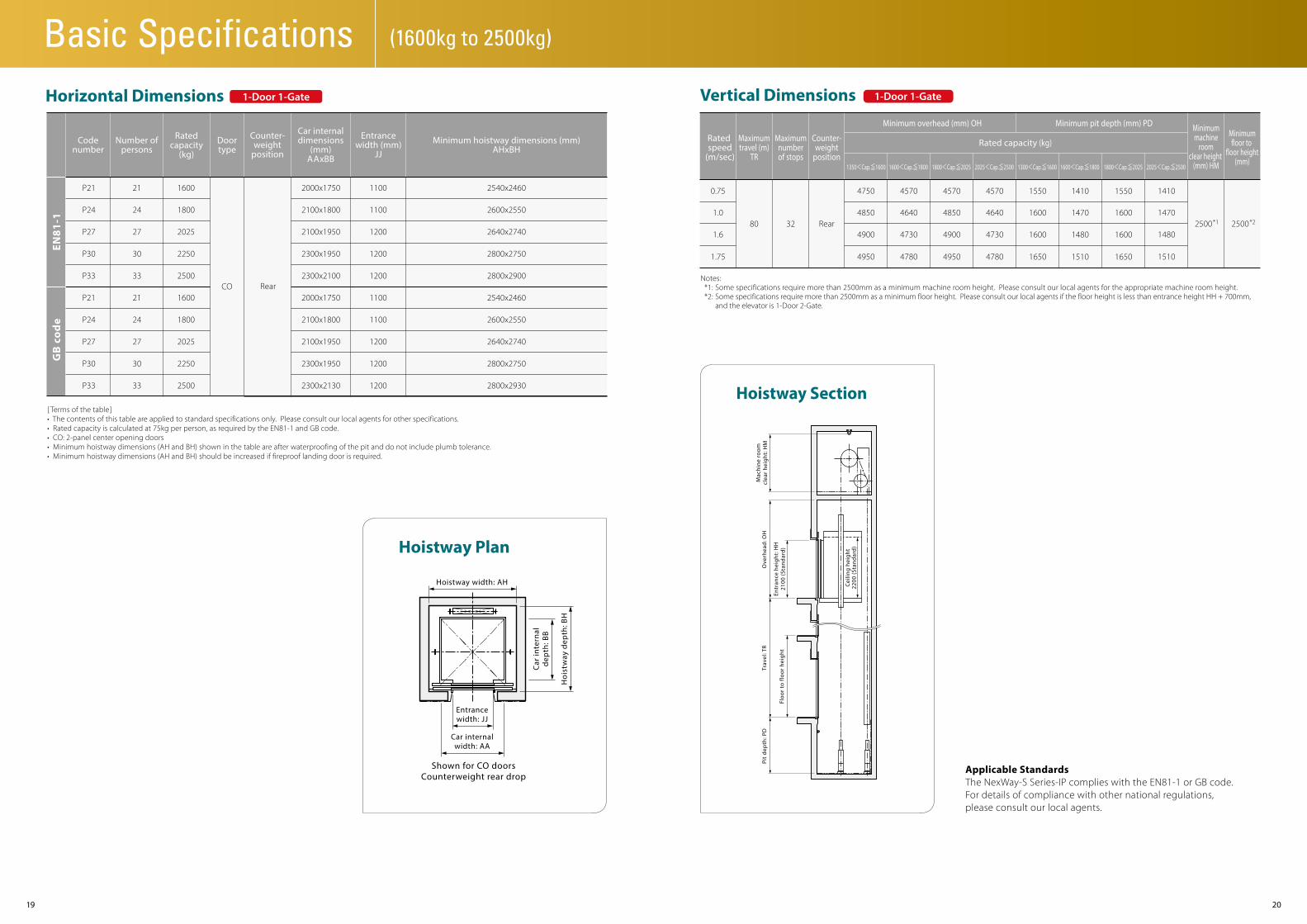
[ Terms of the table]• The contents of this table are applied to standard specifications only. Please consult our local agents for other specifications.• Rated capacity is calculated at 75kg per person, as required by the EN81-1 and GB code.• CO: 2-panel center opening doors• Minimum hoistway dimensions (AH and BH) shown in the table are after waterproofing of the pit and do not include plumb tolerance.• Minimum hoistway dimensions (AH and BH) should be increased if fireproof landing door is required.
Horizontal Dimensions 1-Door 1-Gate
Hoistway width: AH
Entrancewidth: JJ
Car internalwidth: AA
Car
inte
rnal
dep
th: B
B
Hoi
stw
ay d
epth
: BH
Shown for CO doorsCounterweight rear drop
Rated speed
(m/sec)
Maximumtravel (m)
TR
Maximumnumberof stops
Minimummachine
roomclear height
(mm) HM
Minimumfloor to
floor height(mm)
Minimum overhead (mm) OH Minimum pit depth (mm) PD
Rated capacity (kg)
1350<Cap.≦1600 1600<Cap.≦1800 1800<Cap.≦2025 2025<Cap.≦2500 1300<Cap.≦1600 1600<Cap.≦1800 1800<Cap.≦2025 2025<Cap.≦2500
Counter-weight
position
Rear
0.75
1.0
1.6
1.75
4750
4850
4900
4950
4570
4640
4730
4780
4570
4850
4900
4950
4570
4640
4730
4780
1550
1600
1600
1650
1410
1470
1480
1510
1550
1600
1600
1650
80 32
Notes: *1: Some specifications require more than 2500mm as a minimum machine room height. Please consult our local agents for the appropriate machine room height. *2: Some specifications require more than 2500mm as a minimum floor height. Please consult our local agents if the floor height is less than entrance height HH + 700mm, and the elevator is 1-Door 2-Gate.
Vertical Dimensions 1-Door 1-Gate
1410
1470
1480
1510
2500 *1 2500 *2
Applicable StandardsThe NexWay-S Series-IP complies with the EN81-1 or GB code. For details of compliance with other national regulations, please consult our local agents.
Hoistway Plan
Hoistway Section
Mac
hine
roo
mcl
ear
heig
ht: H
MO
verh
ead
: OH
Entr
ance
hei
ght:
HH
2100
(Sta
ndar
d)
Cei
ling
heig
ht22
00 (S
tand
ard
)
Trav
el: T
R
Floo
r to
floo
r he
ight
Pit
dep
th: P
D
2221
Work Not Included in Elevator Contract
Ordering Information
The following items are excluded from Mitsubishi Electric’s elevator installation work, and are therefore the responsibility of the building owner or general contractor: • Construction of the elevator machine room with proper beams and slabs, equipped with a lock, complete with illumination, ventilation and
waterproofing.• Access to the elevator machine room sufficient to allow passage of the control panel and traction machine.• Architectural finishing of the machine room floor, and the walls and floors in the vicinity of the entrance hall after installation has been completed.• Construction of an illuminated, ventilated and waterproofed elevator hoistway.• A ladder to the elevator pit.• The provision of cutting the necessary openings and joists.• Separate beams, when the hoistway dimensions markedly exceed the specifications, and intermediate beams when two or more elevators are installed.• All other work related to building construction.• The machine room power-receiving panel and the electrical wiring for illumination, plus the electrical wiring from the electrical room to the
power-receiving panel.• The laying of conduits and wiring between the elevator pit and the terminating point for the devices installed outside the hoistway, such as the
emergency bell, intercom, monitoring and security devices, etc.• The power consumed in installation work and test operations.• All the necessary building materials for grouting in of brackets, bolts, etc.• The test provision and subsequent alteration as required, and eventual removal of the scaffolding as required by the elevator contractor, and any other
protection of the work as may be required during the process.• The provision of a suitable, locked space for the storage of elevator equipment and tools during elevator installation.• The security system, such as a card reader, connected to Mitsubishi Electric’s elevator controller, when supplied by the building owner or general
contractor.* Work responsibilities in installation and construction shall be determined according to local laws. Please consult our local agents for details.
• The temperature of the machine room and elevator hoistway shall be below 40˚C.• The following conditions are required for maintaining elevator performance.
a. The relative humidity shall be below 90% on a monthly average and below 95% on a daily average.b. Prevention shall be provided against icing and condensation occurring due to a rapid drop in the temperature in the machine room and elevator hoistway.c. The machine room and the elevator hoistway shall be finished with mortar or other materials so as to prevent concrete dust.
• Voltage fluctuation shall be within a range of +5% to -10%.
Please include the following information when ordering or requesting estimates:• The desired number of units, speed and loading capacity.• The number of stops or number of floors to be served.• The total elevator travel and each floor-to-floor height.• Operation system.• Selected design and size of car.• Entrance design.• Signal equipment.• A sketch of the part of the building where the elevators are to be installed.• The voltage, number of phases, and frequency of the power source for the motor and lighting.
Mitsubishi Elevator Asia Co., Ltd. has acquired ISO 9001 certification from the International Organization for Standardization based on a review of quality management.The company has also acquired environmental management system standard ISO 14001 certification.
Important Information on Elevator Planning
Mitsubishi Elevator Inazawa Works has acquired ISO 9001 certification from the International Organization for Standardization based on a review of quality management.The company has also acquired environmental management system standard ISO 14001 certification.
Elevator Site Requirements

C-CL1-3-C9115-B INA-1308 Printed in Japan (MDOC) 2013
Revised publication effective Aug.2013.Superseding publication of C-CL1-3-C9115-A Mar.2013.
Specifications are subject to change without notice.
PASSENGER ELEVATOR(COMPACT MACHINE ROOM SYSTEM)Series-IP/AP Version2Series-IP
Eco Changes is the Mitsubishi Electric Group’s environmental statement,and expresses the Group’s stance on environmental management. Through a wide range of businesses, we are helping contribute to the realization of a sustainable society.
Visit our website at:http://www.mitsubishielectric.com/elevator/