Embed Size (px)
Citation preview

1800kg, 2025kg, 2250kg, 2500kg
PASSENGER ELEVATOR(MACHINE-ROOM-LESS SYSTEM)Series-IP Version2
Eco Changes is the Mitsubishi Electric Group’s environmental statement,and expresses the Group’s stance on environmental management. Through a wide range of businesses, we are helping contribute to the realization of a sustainable society.
Visit our website at:http://www.mitsubishielectric.com/elevator/

21

Mitsubishi Electric elevators, escalators and building management systems are always evolving, helping achieve our goal of being the No.1 brand in quality.In order to satisfy customers in all aspects of comfort, efficiency and safety while realizing a sustainable society, quality must be of the highest level in all products and business activities, while priority is place on consideration for the environment. As the times change, Mitsubishi Electric promises to utilize the collective strengths of its advanced and environmental technologies to offer its customers safe and reliable products while contributing to society.
Based on our policy, “Quality in Motion”,
we provide elevators and escalators that will
satisfy our customers with high levels of
comfort, efficiency, ecology and safety.
Principle
We strive to be green in all of our business activities.We take every action to reduce environmental burden during each process of our elevators’ and escalators’ lifecycle.
Contents
Application
Machine-room-less 7–8
Group Control 9–10
Standard design 11–12
Features 13–16
Basic Specifications and Important Information on Elevator Planning 17–18
5–6Green Technology
1.75
1.6
1.0
1800 2025 2250 2500 (kg)
(m/sec)
(Series-IP Version2)
3 4
Green Technology
SUSTAINABLE ENERGY USEMitsubishi Electric’s leading-edge technologies have made it possible for elevators to conserve energy. Our regenerative converter makes the most of power generated by the traction machine. Additionally, thanks to the joint-lapped core in permanent magnet (PM) motor and energy-saving features, the elevators use energy more wisely and efficiently.
Regenerative Converter (PCNV) (Optional)Joint-lapped Core in PermanentMagnet (PM) Motor Energy-saving Features
Smaller carbon footprintThe joint-lapped core built in the PM motor of the traction machine features flexible joints. The iron core can be like a hinge, which allows coils to be wound around the core more densely, resulting in improved motor efficiency and compactness. High-density magnetic field is produced, enabling lower use of energy and resources and reduced CO2 emissions.
Curbing energy consumptionMitsubishi Electric offers features that help to reduce the energy consumption of elevators.
Energy-saving Operation– Number of Cars (ESO-N) (Optional for ΣAI-22)The number of service cars is automatically reduced to some extent without affecting passenger waiting time.
Energy-saving Operation– Allocation Control (ESO-W) (ΣAI-2200C only)Based on each elevator’s potential energy consumption, the system selects the elevator that best balances operational efficiency and energy consumption.
Car Light/Fan Shut Off– Automatic (CLO-A/CFO-A)The car lighting/ventilation fan is automatically turned off if there are no calls for a specified period.
Efficient use of powerElevators usually travel using power from a power supply (powered operation); however, when they travel down with a heavy car load or up with a light car load (regenerative operation), the traction machine functions as a power generator. Although the power generated during traction machine operation is usually dissipated as heat, the regenerative converter transmits the power back to the distribution transformer and feeds it into the electrical
network in the building along with electricity from the power supply. Compared to the same type of elevator without a regenerative converter, this system provides an energy-saving effect of up to 35%. (Reduction in CO2 emissions: 1400 kg/year)In addition, the regenerative converter has the effect of decreasing harmonic currents.
Using Energy Wisely Our long-term commitment to developing energy-efficient elevators has created systems and functions that make intelligent use of power.
Milestones of Energy-saving Technologies in Elevator Development
Notes:*1: Alternative current, variable voltage*2: Variable voltage, variable frequency*3: • CO2 emissions in this table are from elevator
operation and do not include emissions frommanufacturing, transportation and other processes.
• Calculated from the power consumption with coefficient of 0.6kg/kWh.• The CO2 emissions values in this table vary according to conditions.
Powered operation Regenerative operation
Distribution transformerPower supply
Motor
Control panel & regenerative converter
Distribution transformerPower supply
Motor
Control panel & regenerative converter
5 6
Machine-room-less
SPACE-SAVINGAs all equipment is installed within the hoistway, there are fewer restrictions on building design except for the actual space required for the shaft. Architects and interior designers have more design freedom. Compact PM Gearless Machine Slim Control Panel
The gearless traction machine with a PM (permanent magnet) motor is packed with cutting-edge technology, such as our unique stator-core structure and built-in double brakes.This optimized motor design dramatically reduces the level of torque ripple, which positively affects the quality of the ride. So even though the machinery is compact, the ride is smooth, quiet and comfortable.
Furthermore, the PM motor suppresses harmonic noise and torque ripple, providing greater riding comfort.
More technological advances, such as the high-accumulation LSI and low-noise PWM inverter, enable the VVVF (variable voltage, variable frequency) inverter to deliver smooth, high-precision control of the traction machine. In addition, an IPU (Integrated Power Unit) acts as a high-efficiency power supply circuit for the motor drive and, along with the PM motor, delivers great energy-savings. The result is more efficient, more reliable drive control.
Compact PM Gearless Machine
Slim Control Panel
7 8
0
5
10
15
20
25
30
Morning uppeak
Lunchtime Eveningdown peak
Daytime0
2
4
6
8
10
Morning uppeak
Lunchtime Eveningdown peak
Daytime
Average waiting time Long-wait rate (60 seconds or longer) (sec) (%)
AI-2100N (Conventional system)
AI-2200C
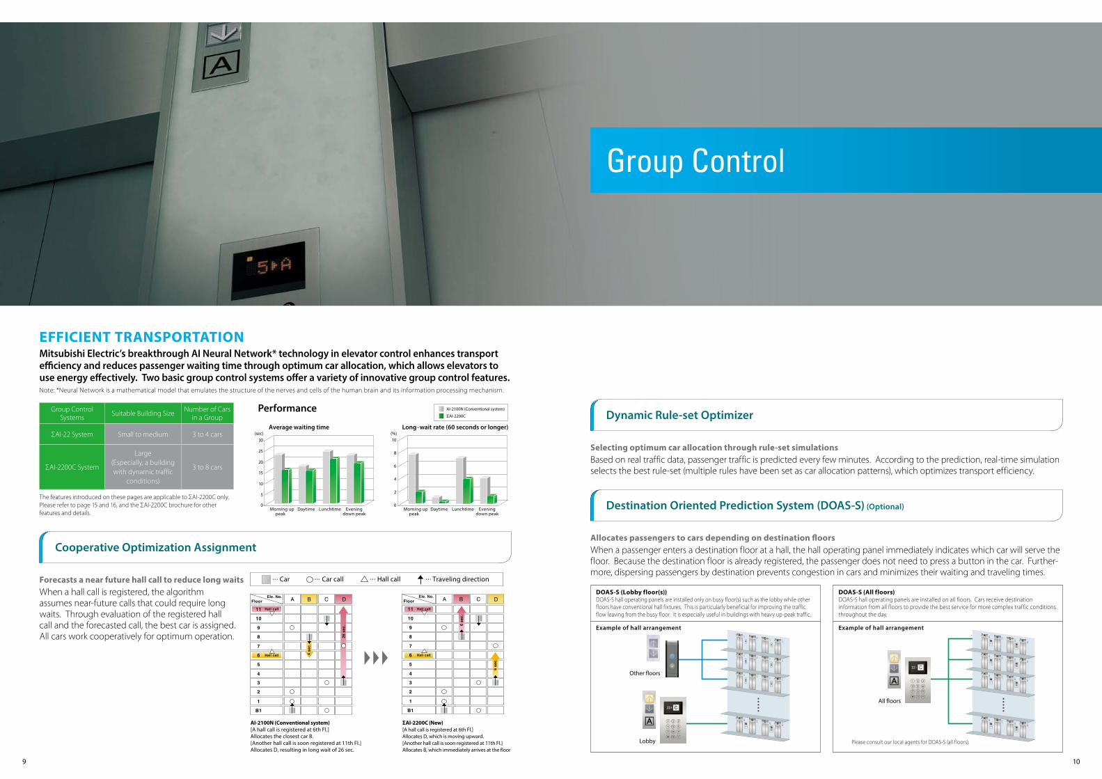
AI-2100N (Conventional system)[A hall call is registered at 6th Fl.]Allocates the closest car B.[Another hall call is soon registered at 11th Fl.]Allocates D, resulting in long wait of 26 sec.
ΣAI-2200C (New)[A hall call is registered at 6th Fl.]Allocates D, which is moving upward.[Another hall call is soon registered at 11th Fl.]Allocates B, which immediately arrives at the floor.
Ele. No.
Hall call Traveling directionCar callCar
Ele. No.
0
5
10
15
20
25
30
Morning uppeak
Lunchtime Eveningdown peak
Daytime0
2
4
6
8
10
Morning uppeak
Lunchtime Eveningdown peak
Daytime
Average waiting time Long-wait rate (60 seconds or longer) (sec) (%)
AI-2100N (Conventional system)
AI-2200C
AI-2100N (Conventional system)[A hall call is registered at 6th Fl.]Allocates the closest car B.[Another hall call is soon registered at 11th Fl.]Allocates D, resulting in long wait of 26 sec.
ΣAI-2200C (New)[A hall call is registered at 6th Fl.]Allocates D, which is moving upward.[Another hall call is soon registered at 11th Fl.]Allocates B, which immediately arrives at the floor.
Ele. No.
Hall call Traveling directionCar callCar
Ele. No.
Group Control
EFFICIENT TRANSPORTATION Mitsubishi Electric’s breakthrough AI Neural Network* technology in elevator control enhances transport efficiency and reduces passenger waiting time through optimum car allocation, which allows elevators to use energy effectively. Two basic group control systems offer a variety of innovative group control features.
Dynamic Rule-set Optimizer
Destination Oriented Prediction System (DOAS-S) (Optional)
Cooperative Optimization Assignment
Selecting optimum car allocation through rule-set simulationsBased on real traffic data, passenger traffic is predicted every few minutes. According to the prediction, real-time simulation selects the best rule-set (multiple rules have been set as car allocation patterns), which optimizes transport efficiency.
Allocates passengers to cars depending on destination floorsWhen a passenger enters a destination floor at a hall, the hall operating panel immediately indicates which car will serve the floor. Because the destination floor is already registered, the passenger does not need to press a button in the car. Further-more, dispersing passengers by destination prevents congestion in cars and minimizes their waiting and traveling times.
Forecasts a near future hall call to reduce long waitsWhen a hall call is registered, the algorithm assumes near-future calls that could require long waits. Through evaluation of the registered hall call and the forecasted call, the best car is assigned. All cars work cooperatively for optimum operation.
Note: *Neural Network is a mathematical model that emulates the structure of the nerves and cells of the human brain and its information processing mechanism.
Group ControlSystems Suitable Building Size Number of Cars
in a Group
ΣAI-22 System Small to medium 3 to 4 cars
ΣAI-2200C System
Large(Especially, a buildingwith dynamic traffic
conditions)
3 to 8 cars
The features introduced on these pages are applicable to ΣAI-2200C only. Please refer to page 15 and 16, and the ΣAI-2200C brochure for other features and details.
DOAS-S (Lobby floor(s))DOAS-S hall operating panels are installed only on busy floor(s) such as the lobby while other floors have conventional hall fixtures. This is particularly beneficial for improving the traffic flow leaving from the busy floor. It is especially useful in buildings with heavy up-peak traffic.
DOAS-S (All floors)DOAS-S hall operating panels are installed on all floors. Cars receive destination information from all floors to provide the best service for more complex traffic conditions throughout the day.
Example of hall arrangement
All floors
Please consult our local agents for DOAS-S (all floors).
Other floors
Lobby
Example of hall arrangement
Performance
9 10

Standard design
Car HallCar operating panel Hall position indicators and buttons
Car Design Example
Walls SUS-HLTransom panel SUS-HLDoors SUS-HLFront return panels SUS-HLKickplate AluminumFlooring PR803Car operating panel CBV1-C760
Hall Design Example
Jamb SUS-HLDoors SUS-HLHall position indicatorand button PIV1-A710N Boxless
Ceiling : Painted steel sheet (Y033) with a milky white resin lighting coverLighting : Central lighting
Notes:*1: Maximum number of floors: 22 floors *2: Some letters of the alphabets are not available. Please consult our local agents for details.
For front return panel Metal-like resin faceplates
CBV1-C760*1
Segment LED indicators*2
Tactile button with yellow-orange lighting
PIV1-A710N Boxless PIV1-A720N Boxless
Segment LED indicators*2
Tactile button with yellow-orange lighting
Actual colors may differ slightly from those shown.Please refer to the design guide for details and other designs.
Ceiling: S00 Narrow Jamb: E-102
Yellow-orange lighting
Tactile button
11 12
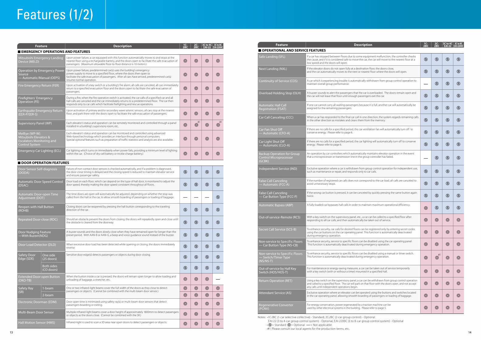
Feature Description 1C-2BC
2C-2BC
3C to 4CΣAI-22
3C to 8CΣAI-2200C
n EMERGENCY OPERATIONS AND FEATURES
Mitsubishi Emergency LandingDevice (MELD)
Upon power failure, a car equipped with this function automatically moves to and stops at the nearest floor using a rechargeable battery, and the doors open to facilitate the safe evacuation of passengers. (Maximum allowable floor-to-floor distance is 10 meters.)
Operation by Emergency PowerSource — Automatic/Manual (OEPS)
Upon power failure, predetermined car(s) uses the building’s emergencypower supply to move to a specified floor, where the doors then open tofacilitate the safe evacuation of passengers. After all cars have arrived, predetermined car(s) resume normal operation.
Fire Emergency Return (FER) Upon activation of a key switch or a building’s fire alarm, all calls are canceled, all cars immediately return to a specified evacuation floor and the doors open to facilitate the safe evacuation of passengers.
Firefighters’ EmergencyOperation (FE)
During a fire, when the fire operation switch is activated, the car calls of a specified car and all hall calls are canceled and the car immediately returns to a predetermined floor. The car then responds only to car calls which facilitate firefighting and rescue operations.
Earthquake Emergency Return(EER-P/EER-S)
Upon activation of primary and/or secondary wave seismic sensors, all cars stop at the nearest floor, and park there with the doors open to facilitate the safe evacuation of passengers.
Supervisory Panel (WP) Each elevator’s status and operation can be remotely monitored and controlled through a panel installed in a building’s supervisory room, etc.
#1 #1
MelEye (WP-W)Mitsubishi Elevators & Escalators Monitoring and Control System
Each elevator’s status and operation can be monitored and controlled using advanced Web-based technology which provides an interface through personal computers. Special optional features such as preparation of traffic statistics and analysis are also available.
Emergency Car Lighting (ECL) Car lighting which turns on immediately when power fails, providing a minimum level of lighting within the car. (Choice of dry-cell battery or trickle-charge battery.)
n DOOR OPERATION FEATURES
Door Sensor Self-diagnosis(DODA)
Failure of non-contact door sensors is checked automatically, and if a problem is diagnosed,the door-close timing is delayed and the closing speed is reduced to maintain elevator service and ensure passenger safety.
Automatic Door Speed Control(DSAC)
Door load on each floor, which can depend on the type of hall door, is monitored to adjust the door speed, thereby making the door speed consistent throughout all floors.
Automatic Door-open TimeAdjustment (DOT)
The time doors are open will automatically be adjusted, depending on whether the stop was called from the hall or the car, to allow smooth boarding of passengers or loading of baggage.
Reopen with Hall Button(ROHB)
Closing doors can be reopened by pressing the hall button corresponding to the traveling direction of the car.
Repeated Door-close (RDC) Should an obstacle prevent the doors from closing, the doors will repeatedly open and close until the obstacle is cleared from the doorway.
Door Nudging Feature—With Buzzer(NDG)
A buzzer sounds and the doors slowly close when they have remained open for longer than the preset period. With AAN-B or AAN-G, a beep and voice guidance sound instead of the buzzer.
Door Load Detector (DLD) When excessive door load has been detected while opening or closing, the doors immediately reverse.
Safety Door Edge (SDE)
One side(2S doors)
Sensitive door edge(s) detects passengers or objects during door closing.
Both sides(CO doors)
Extended Door-open Button(DKO-TB)
When the button inside a car is pressed, the doors will remain open longer to allow loading and unloading of baggage, a stretcher, etc.
Safety Ray (SR)
1-beam One or two infrared-light beams cover the full width of the doors as they close to detect passengers or objects. (Cannot be combined with the multi-beam door sensor.)
2-beam
Electronic Doorman (EDM) Door open time is minimized using safety ray(s) or multi-beam door sensors that detect passengers boarding or exiting.
Multi-Beam Door Sensor Multiple infrared-light beams cover a door height of approximately 1800mm to detect passengers or objects as the doors close. (Cannot be combined with the SR.)
Hall Motion Sensor (HMS) Infrared-light is used to scan a 3D area near open doors to detect passengers or objects.
Features (1/2)
Feature Description 1C-2BC
2C-2BC
3C to 4CΣAI-22
3C to 8CΣAI-2200C
n OPERATIONAL AND SERVICE FEATURES
Safe Landing (SFL) If a car has stopped between floors due to some equipment malfunction, the controller checks the cause, and if it is considered safe to move the car, the car will move to the nearest floor at a low speed and the doors will open.
Next Landing (NXL) If the elevator doors do not open fully at a destination floor, the doors close, and the car automatically moves to the next or nearest floor where the doors will open.
Continuity of Service (COS) A car which is experiencing trouble is automatically withdrawn from group control operation to maintain overall group performance.
Overload Holding Stop (OLH) A buzzer sounds to alert the passengers that the car is overloaded. The doors remain open and the car will not leave that floor until enough passengers exit the car.
Automatic Hall Call Registration (FSAT)
If one car cannot carry all waiting passengers because it is full, another car will automatically be assigned for the remaining passengers.
Car Call Canceling (CCC) When a car has responded to the final car call in one direction, the system regards remaining calls in the other direction as mistakes and clears them from the memory.
Car Fan Shut Off — Automatic (CFO-A)
If there are no calls for a specified period, the car ventilation fan will automatically turn off to conserve energy. Please refer to page 6.
Car Light Shut Off — Automatic (CLO-A)
If there are no calls for a specified period, the car lighting will automatically turn off to conserve energy. Please refer to page 6.
Backup Operation for GroupControl Microprocessor (GCBK)
An operation by car controllers which automatically maintains elevator operation in the event that a microprocessor or transmission line in the group controller has failed.
Independent Service (IND) Exclusive operation where a car is withdrawn from group control operation for independent use, such as maintenance or repair, and responds only to car calls.
False Call Canceling — Automatic (FCC-A)
If the number of registered car calls does not correspond to the car load, all calls are canceled to avoid unnecessary stops.
False Call Canceling — Car Button Type (FCC-P)
If the wrong car button is pressed, it can be canceled by quickly pressing the same button again twice.
Automatic Bypass (ABP) A fully-loaded car bypasses hall calls in order to maintain maximum operational efficiency.
Out-of-service-Remote (RCS) With a key switch on the supervisory panel, etc., a car can be called to a specified floor after responding to all car calls, and then automatically be taken out of service.
Secret Call Service (SCS-B) To enhance security, car calls for desired floors can be registered only by entering secret codes using the car buttons on the car operating panel. This function is automatically deactivated during emergency operation.
Non-service to Specif ic Floors— Car Button Type (NS-CB)
To enhance security, service to specific floors can be disabled using the car operating panel. This function is automatically deactivated during emergency operation.
Non-service to Specif ic Floors— Switch/Timer Type (NS/NS-T)
To enhance security, service to specific floors can be disabled using a manual or timer switch. This function is automatically deactivated during emergency operation.
#1
Out-of-service by Hall KeySwitch (HOS/HOS-T)
For maintenance or energy-saving measures, a car can be taken out of service temporarily with a key switch (with or without a timer) mounted in a specified hall.
Return Operation (RET) Using a key switch on the supervisory panel, a car can be withdrawn from group control operation and called to a specified floor. The car will park on that floor with the doors open, and not accept any calls until independent operations begin.
Attendant Service (AS) Exclusive operation where an elevator can be operated using the buttons and switches located in the car operating panel, allowing smooth boarding of passengers or loading of baggage.
Regenerative Converter(PCNV)
For energy conservation, power regenerated by a traction machine can beused by other electrical systems in the building. Please refer to page 5.
Notes: •1C-2BC (1-car selective collective) - Standard, 2C-2BC (2-car group control) - OptionalΣAI-22 (3 to 4-car group control system) - Optional, ΣAI-2200C (3 to 8-car group control system) - Optional
• = Standard = Optional = Not applicable•#1: Please consult our local agents for the production terms, etc.
13 14

Features (2/2)
Feature Description 1C-2BC
2C-2BC
3C to 4CΣAI-22
3C to 8CΣAI-2200C
n GROUP CONTROL FEATURES
Expert System and Fuzzy Logic Artificial expert knowledge, which has been programmed using “expert system” and “fuzzy logic”, is applied to select the ideal operational rule which maximizes the efficiency of group control operations.
Psychological Waiting TimeEvaluation
Cars are allocated according to the predicted psychological waiting time for each hall call. The rules evaluating psychological waiting time are automatically changed in a timely manner in response to actual service conditions.
Cooperative OptimizationAssignment
The system predicts a potential hall call, which could cause longer waiting time. Car assignment is performed considering not only current and new calls but also near-future calls. Please refer to page 9.
Car Travel Time Evaluation Cars are allocated to hall calls by considering the number of car calls that will reduce passenger waiting time in each hall and the travel time of each car.
Distinction of Traffic Flow withNeural Networks (NN)
Traffic flows in a building are constantly monitored using neural network technology, and the optimum operational pattern, such as Lunchtime Service or Up Peak Service, is selected or canceled accordingly at the appropriate time.
Car Allocation Tuning (CAT) The number of cars allocated or parked on crowded floors is controlled not just according to the conditions on those crowded floors but also the operational status of each car and the traffic on each floor.
Dynamic Rule-set Optimizer(DRO)
Traffic flows in a building are constantly predicted using neural network technology, and an optimum rule-set for group control operations is selected through real-time simulations based on prediction results. Please refer to page 10.
Peak Traffic Control (PTC) A floor which temporarily has the heaviest traffic is served with higher priority over other floors, but not to the extent that it interferes with the service to other floors.
Strategic Overall Spotting(SOHS)
To reduce passenger waiting time, cars which have finished service are automatically directed to positions where they can respond to predicted hall calls as quickly as possible.
Energy-saving Operation — Allocation Control (ESO-W)
The system selects the elevator that best balances operational efficiency and energy consumption according to each elevator’s current location and passenger load as well as predicted congestion levels throughout the day. Please refer to page 6.
Energy-saving Operation — Number of Cars (ESO-N)
To save energy, the number of service cars is automatically reduced to some extent, but not so much that it adversely affects passenger waiting time. Please refer to page 6.
Destination Oriented Prediction System (DOAS-S)
When a passenger enters a destination floor at a hall, the hall operating panel indicates which car will serve the floor. The passenger does not need to press a button in the car. Dispersing passengers by destination prevents congestion in the cars and minimizes their waiting and traveling times. Please refer to page 10.
#2
Up Peak Service (UPS) Controls the number of cars to be allocated to the lobby floor, as well as the car allocation timing, in order to meet increased demands for upward travel from the lobby floor during office starting time, hotel check-in time, etc., and minimize passenger waiting time.
Down Peak Service (DPS) Controls the number of cars to be allocated and the timing of car allocation in order to meet increased demand for downward travel during office leaving time, hotel check-out times etc., and minimize passenger waiting time.
Main Floor Parking (MFP) An available car always parks on the main (lobby) floor with the doors open/closed (China only).
Forced Floor Stop (FFS) All cars in a bank automatically make a stop at a predetermined floor on every trip without being called.
Special Floor Priority Service(SFPS)
Special floors, such as floors with VIP rooms or executive rooms, are given higher priority for car allocation when a call is made on those floors. (Cannot be combined with hall position indicators.)
#1
Closest-car Priority Service(CNPS)
A function to give priority allocation to the car closest to the floor where a hall call button has been pressed, or to reverse the closing doors of the car closest to the pressed hall call button on that floor. (Cannot be combined with hall position indicators.)
#1
Light-load Car Priority Service(UCPS)
When traffic is light, empty or lightly-loaded cars are given higher priority to respond to hall calls in order to minimize passenger travel time. (Cannot be combined with hall position indicators.)
#1
Special Car Priority Service(SCPS)
Special cars, such as observation elevators and elevators with basement service, are given higher priority to respond to hall calls. (Cannot be combined with hall position indicators.)
#1
Congested-floor Service (CFS)
The timing of car allocation and the number of cars to be allocated to floors where meeting rooms or ballrooms exist and the traffic intensifies for short periods of time are controlled according to the detected traffic density data for those floors.
Feature Description 1C-2BC
2C-2BC
3C to 4CΣAI-22
3C to 8CΣAI-2200C
Bank-separation Operation(BSO)
Hall buttons and the cars called by each button can be divided into several groups for independent group control operation to serve special needs or different floors.
#1
VIP Operation (VIP-S) A specified car is withdrawn from group control operation for VIP service operation. When activated, the car responds only to existing car calls, moves to a specified floor and parks there with the doors open. The car will then respond only to car calls.
#1
Lunchtime Service (LTS) During the first half of lunchtime, calls for a restaurant floor are served with higher priority, and during the latter half, the number of cars allocated to the restaurant floor, the allocation timing for each car and the door opening and closing timing are all controlled based on predicted data.
Main Floor ChangeoverOperation (TFS)
This feature is effective for buildings with two main (lobby) floors. The floor designated as the “main floor” in a group control operation can be changed as necessary using a manual switch.
n SIGNAL AND DISPLAY FEATURES
Basic Announcement (AAN-B) A synthetic voice (and/or buzzer) alerts passengers inside a car that elevator operation has been temporarily interrupted due to overloading or a similar cause. (Voice available only in English.)
Flashing Hall Lantern (FHL) A hall lantern, which corresponds to a car’s service direction, flashes to indicate that the car will soon arrive.
Car Arrival Chime — Car or Hall (AECC/AECH)
Electronic chimes sound to indicate that a car will soon arrive. (The chimes are mounted either on the top and bottom of the car, or in each hall.)
(Each floor)
Sonic Car Button — Click Type (ACB)
A click-type car button which emits an electronic beep sound when pressed to indicate that the call has been registered.
Immediate Prediction Indication (AIL)
When a passenger has registered a hall call, the best car to respond to that call is immediately selected, the corresponding hall lantern lights up and a chime sounds once to indicate which doors will open.
Second Car Prediction (TCP) When a hall is crowded to the extent that one car cannot accommodate all waiting passengers, a hall lantern will light up to indicate the next car to serve the hall.
Voice Guidance System(AAN-G)
Information on elevator service such as the current floor or service direction is given to the passengers inside a car. (Voice guidance available only in English.)
Auxiliary Car Operating Panel(ACS)
An additional car operating panel which can be installed for large-capacity elevators, heavy-traffic elevators, etc.
Inter-communication System(ITP)
A system which allows communication between passengers inside a car and the building personnel.
LCD Position Indicator (CID-S) This 5.7-inch LCD for car operating panels shows the date and time, car positions, travel direction and elevator status messages.
Hall LCD Position Indicator(HID-S)
This 5.7-inch LCD for elevator halls shows the date and time, car position, travel direction and elevator status messages.
Car Information Display (CID) This LCD (10.4- or 15-inch) for car front return panels shows the date and time, car position, travel direction and elevator status messages.
Hall Information Display (HID) This LCD (10.4- or 15-inch) for elevator halls shows the date and time, car position, travel direction and elevator status messages.
Notes: •1C-2BC (1-car selective collective) - Standard, 2C-2BC (2-car group control) - OptionalΣAI-22 (3 to 4-car group control system) - Optional, ΣAI-2200C (3 to 8-car group control system) - Optional
• = Standard = Optional = Not applicable•#1: Please consult our local agents for the production terms, etc.•#2: When DOAS-S is applied, SR or Multi-Beam Door Sensor should be installed.
Please consult our local agents when DOAS-S hall operating panels are installed on all floors.
15 16
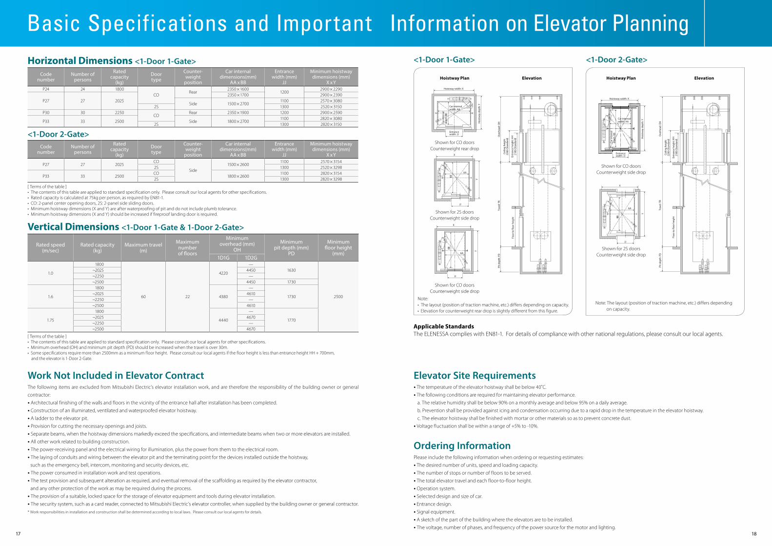
Basic Specifications and Important Information on Elevator PlanningHorizontal Dimensions <1-Door 1-Gate>
Vertical Dimensions <1-Door 1-Gate & 1-Door 2-Gate>
Codenumber
Number ofpersons
Ratedcapacity
(kg)
Doortype
Counter-weight
position
Car internaldimensions(mm)
AA x BB
Entrancewidth (mm)
JJ
Minimum hoistwaydimensions (mm)
X x YP24 24 1800
CORear
2350 ×16001200
2900 × 2290
P27 27 20252350 ×1700 2900 × 2390
Side 1500 × 27001100 2570 × 3080
2S 1300 2520 × 3150P30 30 2250
CORear 2350 ×1900 1200 2900 × 2590
P33 33 2500 Side 1800 × 27001100 2820 × 3080
2S 1300 2820 × 3150
<1-Door 2-Gate>Code
numberNumber of
persons
Ratedcapacity
(kg)
Doortype
Counter-weight
position
Car internaldimensions(mm)
AA x BB
Entrancewidth (mm)
JJ
Minimum hoistwaydimensions (mm)
X x Y
P27 27 2025CO
Side1500 × 2600
1100 2570 × 31542S 1300 2520 × 3298
P33 33 2500CO
1800 × 26001100 2820 × 3154
2S 1300 2820 × 3298
Rated speed(m/sec)
Rated capacity(kg)
Maximum travel(m)
Maximumnumberof floors
Minimumoverhead (mm)
OHMinimum
pit depth (mm)PD
Minimumfloor height
(mm)1D1G 1D2G
1.0
1800
60 22
4220
—1630
2500
~2025 4450~2250 —~2500 4450 1730
1.6
1800
4380
—
1730~2025 4610~2250 —~2500 4610
1.75
1800
4440
—
1770~2025 4670~2250 —~2500 4670
[ Terms of the table ]• The contents of this table are applied to standard specification only. Please consult our local agents for other specifications.• Rated capacity is calculated at 75kg per person, as required by EN81-1.• CO: 2-panel center opening doors, 2S: 2-panel side sliding doors.• Minimum hoistway dimensions (X and Y) are after waterproofing of pit and do not include plumb tolerance.• Minimum hoistway dimensions (X and Y) should be increased if fireproof landing door is required.
[ Terms of the table ]• The contents of this table are applied to standard specification only. Please consult our local agents for other specifications.• Minimum overhead (OH) and minimum pit depth (PD) should be increased when the travel is over 30m.• Some specifications require more than 2500mm as a minimum floor height. Please consult our local agents if the floor height is less than entrance height HH + 700mm,
and the elevator is 1-Door 2-Gate.
Elevator Site Requirements• The temperature of the elevator hoistway shall be below 40˚C.
• The following conditions are required for maintaining elevator performance.
a. The relative humidity shall be below 90% on a monthly average and below 95% on a daily average.
b. Prevention shall be provided against icing and condensation occurring due to a rapid drop in the temperature in the elevator hoistway.
c. The elevator hoistway shall be finished with mortar or other materials so as to prevent concrete dust.
• Voltage fluctuation shall be within a range of +5% to -10%.
Ordering InformationPlease include the following information when ordering or requesting estimates:
• The desired number of units, speed and loading capacity.
• The number of stops or number of floors to be served.
• The total elevator travel and each floor-to-floor height.
• Operation system.
• Selected design and size of car.
• Entrance design.
• Signal equipment.
• A sketch of the part of the building where the elevators are to be installed.
• The voltage, number of phases, and frequency of the power source for the motor and lighting.
Work Not Included in Elevator Contract The following items are excluded from Mitsubishi Electric’s elevator installation work, and are therefore the responsibility of the building owner or general
contractor:
• Architectural finishing of the walls and floors in the vicinity of the entrance hall after installation has been completed.
• Construction of an illuminated, ventilated and waterproofed elevator hoistway.
• A ladder to the elevator pit.
• Provision for cutting the necessary openings and joists.
• Separate beams, when the hoistway dimensions markedly exceed the specifications, and intermediate beams when two or more elevators are installed.
• All other work related to building construction.
• The power-receiving panel and the electrical wiring for illumination, plus the power from them to the electrical room.
• The laying of conduits and wiring between the elevator pit and the terminating point for the devices installed outside the hoistway, such as the emergency bell, intercom, monitoring and security devices, etc.
• The power consumed in installation work and test operations.
• The test provision and subsequent alteration as required, and eventual removal of the scaffolding as required by the elevator contractor, and any other protection of the work as may be required during the process.
• The provision of a suitable, locked space for the storage of elevator equipment and tools during elevator installation.
• The security system, such as a card reader, connected to Mitsubishi Electric’s elevator controller, when supplied by the building owner or general contractor.* Work responsibilities in installation and construction shall be determined according to local laws. Please consult our local agents for details.
<1-Door 1-Gate> <1-Door 2-Gate>
Note:• The layout (position of traction machine, etc.) differs depending on capacity.• Elevation for counterweight rear drop is slightly different from this figure.
Note: The layout (position of traction machine, etc.) differs depending on capacity.
Applicable StandardsThe ELENESSA complies with EN81-1. For details of compliance with other national regulations, please consult our local agents.
Hoistway Plan Hoistway PlanElevation Elevation① ② ③
④ ⑤
Car internalwidth: AA
Hoistway width: X
Entrance width: JJ
JJJJ
Hoistway width: X
Car internalwidth: AA
Car internal
depth: BB
Car internal
depth: BB
Hoistway depth: Y
Hoistway depth: Y
XX
Y
Y
AA
AA
BB
BB
Entrance width: JJ
X
Y
JJ
AA
BB
① ② ③
④ ⑤
Car internalwidth: AA
Hoistway width: X
Entrance width: JJ
JJJJ
Hoistway width: X
Car internalwidth: AA
Car internal
depth: BB
Car internal
depth: BB
Hoistway depth: Y
Hoistway depth: Y
XX
Y
Y
AA
AA
BB
BB
Entrance width: JJ
X
Y
JJ
AA
BB
① ② ③
④ ⑤
Car internalwidth: AA
Hoistway width: X
Entrance width: JJ
JJJJ
Hoistway width: X
Car internalwidth: AA
Car internal
depth: BB
Car internal
depth: BB
Hoistway depth: Y
Hoistway depth: Y
XX
Y
Y
AA
AA
BB
BB
Entrance width: JJ
X
Y
JJ
AA
BB
① ② ③
④ ⑤
Car internalwidth: AA
Hoistway width: X
Entrance width: JJ
JJJJ
Hoistway width: X
Car internalwidth: AA
Car internal
depth: BB
Car internal
depth: BB
Hoistway depth: Y
Hoistway depth: Y
XX
Y
Y
AA
AA
BB
BB
Entrance width: JJ
X
Y
JJ
AA
BB
① ② ③
④ ⑤
Car internalwidth: AA
Hoistway width: X
Entrance width: JJ
JJJJ
Hoistway width: X
Car internalwidth: AA
Car internal
depth: BB
Car internal
depth: BB
Hoistway depth: Y
Hoistway depth: Y
XX
Y
Y
AA
AA
BB
BB
Entrance width: JJ
X
YJJ
AA
BB
Entrance height: HH
2100 (Standard)
Entrance height: HH
2100 (Standard)
Ceiling height
2200 (Standard)
Ceiling height
2200 (Standard)
Floor to floor height
Floor to floor height
Pit depth: PD
Pit depth: PD
Travel: TR
Overhead: OH
Overhead: OH
Travel: TR
① ②
Entrance height: HH
2100 (Standard)
Entrance height: HH
2100 (Standard)
Ceiling height
2200 (Standard)
Ceiling height
2200 (Standard)
Floor to floor height
Floor to floor height
Pit depth: PD
Pit depth: PD
Travel: TR
Overhead: OH
Overhead: OH
Travel: TR
① ②
Shown for CO doors Counterweight rear drop
Shown for CO doorsCounterweight side drop
Shown for 2S doorsCounterweight side drop
Shown for CO doors Counterweight side drop
Shown for 2S doors Counterweight side drop
17 18

Mitsubishi Elevator Inazawa Works has acquired ISO 9001 certification from the International Organization for Standardization based on a review of quality management.The company has also acquired environmental management system standard ISO 14001 certification.
C-CL1-3-C9226-A INA-1309 Printed in Japan (MDOC)
New publication effective Sep. 2013.Specifications are subject to change without notice.
2013
Eco Changes is the Mitsubishi Electric Group’s environmental statement,and expresses the Group’s stance on environmental management. Through a wide range of businesses, we are helping contribute to the realization of a sustainable society.
Visit our website at:http://www.mitsubishielectric.com/elevator/