Embed Size (px)
Citation preview
www.usmicroproducts.com CONFIDENTIAL (800) 741-7755
TFT-LCD PRODUCT SPECIFICATION
PART NUMBER:
DESCRIPTION:
ISSUE DATE APPROVED BY (Customer Use Only)
CHECKED BY PREPARED BY
PROPRIETARY NOTE:
THIS SPECIFICATION IS THE PROPERTY OF US MICRO PRODUCTS AND SHALL NOT BE REPRODUCED OR COPIED WITHOUT THE WRITTEN PERMISSION OF US MICRO PRODUCTS AND MUST BE RETURNED TO
US MICRO PRODUCTS UPON ITS REQUEST.
3.5” TFT LCD with 320 x 240 resolution,
Digital 24-bits RGB Interface and 6 O’Clock Viewing Direction
USMP-TT035Q-01D
History of Version
Date Ver. Edi. Description Page Design by
03/11/2008 0 - New drawing - LIUJIN
04/24/2008 0 - New Sample - LIUJIN
05/28/2008 A -Modify the Module’s Supply Current ,Power
Consumption and Uniformity- LIUJIN
05/30/2008 01 001 Mass Production - LIUJIN
Total: 26 Page
CO
NFID
EN
TIAL
Part # USMP-TT035Q-01D
www.usmicroproducts.com 1 (800) 741-7755
Contents1. SPECIFICATIONS
1.1 Features1.2 Mechanical Specifications1.3 Absolute Maximum Ratings 1.4 DC Electrical Characteristics1.5 Optical Characteristics 1.6 Backlight Characteristics
2. MODULE STRUCTURE2.1 Counter Drawing2.2 Interface Pin Description2.3 Timing Characteristics
3. QUALITY ASSURANCE SYSTEM3.1 Quality Assurance Flow Chart3.2 Inspection Specification
4. RELIABILITY TEST4.1 Reliability Test Condition
5. PRECAUTION RELATING PRODUCT HANDLING5.1 Safety5.2 Handling5.3 Storage5.4 Terms of Warranty
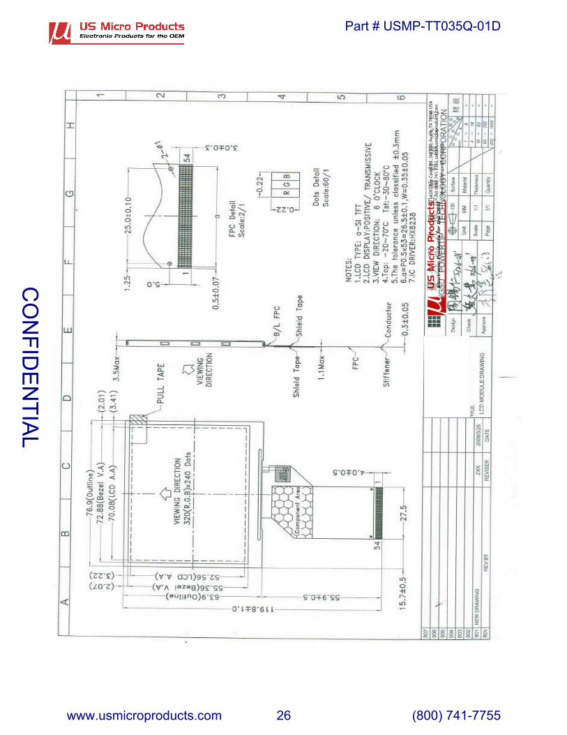
Appendix LCM Drawing
CO
NFID
EN
TIAL
Part # USMP-TT035Q-01D
www.usmicroproducts.com 2 (800) 741-7755
1. SPECIFICATIONS
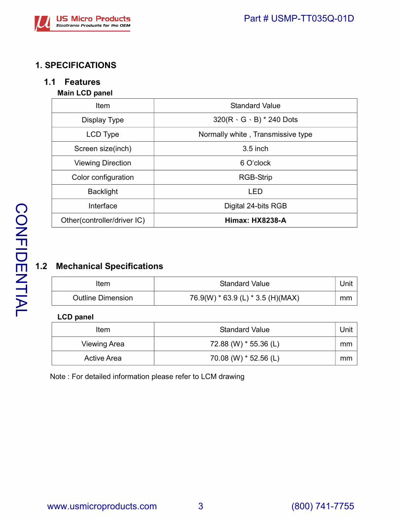
1.1 FeaturesMain LCD panel
eulaVdradnatSmetI
Display Type 320(R G B) * 240 Dots
epytevissimsnarT,etihwyllamroNepyTDCL
hcni5.3)hcni(ezisneercS
O 6noitceriDgniweiV ’clock
pirtS-BGRnoitarugifnoc roloC
DELthgilkcaB
BGRstib-42latigiDecafretnI
Other(controller/driver IC) Himax: HX8238-A
1.2 Mechanical Specifications
tinUeulaVdradnatSmetI
Outline Dimension 76.9(W) * 63.9 (L) * 3.5 (H)(MAX) mm
LCD paneltinUeulaVdradnatSmetI
mm)L( 63.55* )W(88.27aerAgniweiV
mm)L( 65.25* )W(80.07aerAevitcA
Note : For detailed information please refer to LCM drawingC
ON
FIDE
NTIA
L
Part # USMP-TT035Q-01D
www.usmicroproducts.com 3 (800) 741-7755
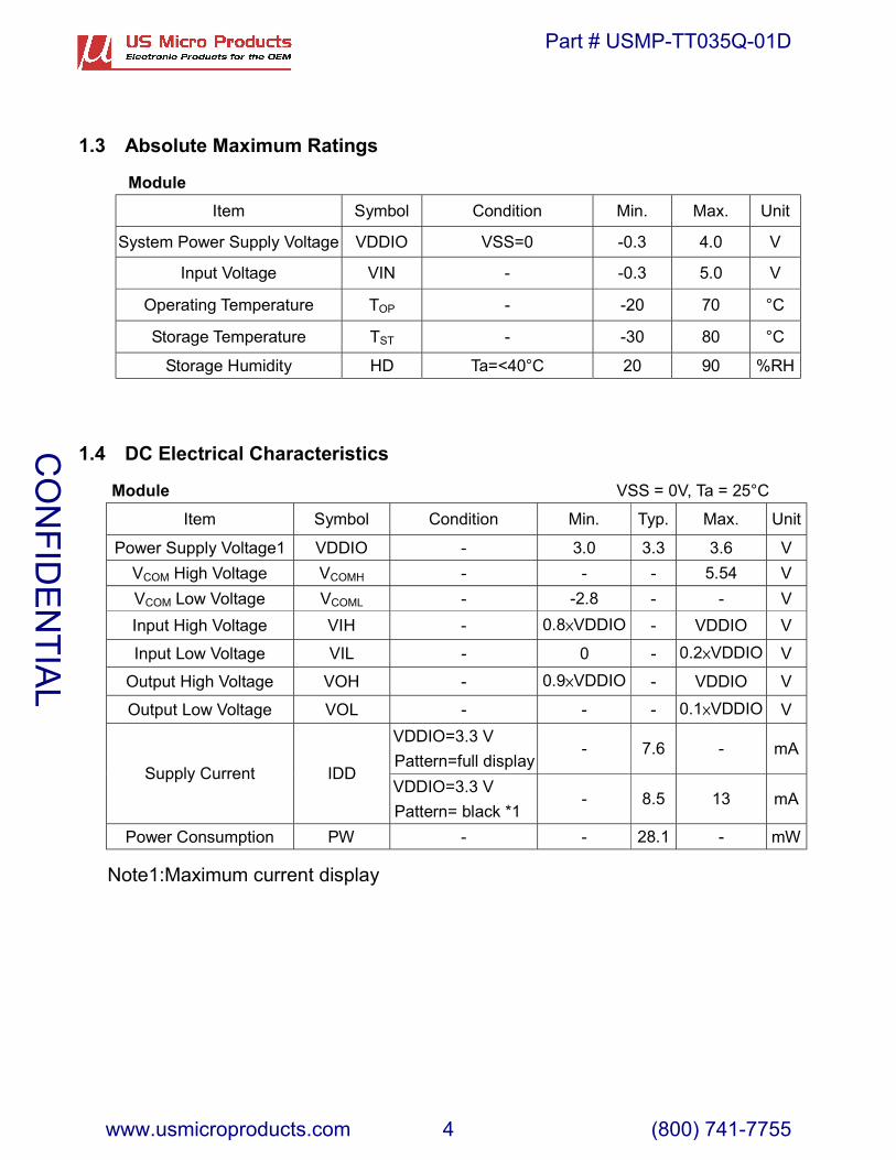
1.3 Absolute Maximum Ratings
ModuleItem Symbol Condition Min. Max. Unit
System Power Supply Voltage VDDIO VSS=0 -0.3 4.0 V
Input Voltage VIN - -0.3 5.0 V
Operating Temperature TOP - -20 70 °C
Storage Temperature TST - -30 80 °C
Storage Humidity HD Ta=<40°C 20 90 %RH
1.4 DC Electrical Characteristics
Module VSS = 0V, Ta = 25°C
Item Symbol Condition Min. Typ. Max. Unit
Power Supply Voltage1 VDDIO - 3.0 3.3 3.6 VVCOM High Voltage VCOMH - - - 5.54 VVCOM Low Voltage VCOML - -2.8 - - VInput High Voltage VIH - 0.8�VDDIO - VDDIO V
Input Low Voltage VIL - 0 - 0.2�VDDIO V
Output High Voltage VOH - 0.9�VDDIO - VDDIO V
Output Low Voltage VOL - - - 0.1�VDDIO VVDDIO=3.3 VPattern=full display
- 7.6 - mASupply Current IDD
VDDIO=3.3 VPattern= black *1
- 8.5 13 mA
Power Consumption PW - - 28.1 - mW
Note1:Maximum current displayC
ON
FIDE
NTIA
L
Part # USMP-TT035Q-01D
www.usmicroproducts.com 4 (800) 741-7755

1.5 Optical CharacteristicsTFT LCD Module VDDIO=3.3V, Ta=25°C
Item Symbol Condition Min. Typ. Max. unit -
Response time Tr+ Tf Ta = 25°CθX, θY = 0°
- 35 53 ms Note2
Top θY+ - 45 -Bottom θY- - 50 -
Left θX- - 50 -Viewing angle
Right θX+
CR ≥ 10
- 50 -
Deg. Note4
Contrast ratio CR 200 250 - - Note3X 0.24 0.29 0.34
WhiteY 0.26 0.31 0.36X 0.57 0.62 0.67
RedY 0.31 0.36 0.41X 0.27 0.32 0.37
GreenY 0.56 0.61 0.66X 0.09 0.14 0.19
Color of CIE Coordinate�With B/L�
BlueY
Ta = 25°CθX , θY = 0°
0.03 0.08 0.13
-
Average BrightnessPattern=white display
(With B/L) *1IV IF=20 mA 240 280 - cd/m2
Uniformity(With B/L)*1
�B IF=20 mA 70 - - %
Note1
Note1:1� �B=B(min) / B(max)
2�Measurement Condition for Optical Characteristics:3�
a�Environment: 25 ±� 5� / 60�20%R.H�no wind�dark room below 10 Lux at typical lamp
current and typical operating frequency.b�Measurement Distance: 500 ± 50 � �(θ= 0°)
c�Equipment: TOPCON BM-7 fast�(field 1)�after 10 minutes operation.
d�The uncertainty of the C.I.E coordinate measurement ±0.01�Average Brightness ± 4%
1 2 3
6 5 4
7 8 9
VIEW AREA
LCM
Colorimeter=BM 7 fast
500�
CO
NFID
EN
TIAL
Part # USMP-TT035Q-01D
www.usmicroproducts.com 5 (800) 741-7755

Note2: Definition of response time: The output signals of photo detector are measured when the input signals arechanged from “black” to “white”(falling time) and from “white” to “black”(rising time),
respectively. The response time is defined as the time interval between the 10% and 90%of Amplitudes.
Refer to figure as below:
100%90%
10%0%
Signal (Relative value)
"Black"
Tr Tf
"White" "White"
Note3: Definition of contrast ratio:Contrast ratio is calculated with the following formula
Photo detector output when LCD is at “White” stateContrast ratio (CR) =
Photo detector output when LCD is at “Black” stateNote4: Definition of viewing angle:
Refer to figure as below:
� �
� �
� �
� �
� �
��
� � �
�
� �
� �
� �
� �
CO
NFID
EN
TIAL
Part # USMP-TT035Q-01D
www.usmicroproducts.com 6 (800) 741-7755
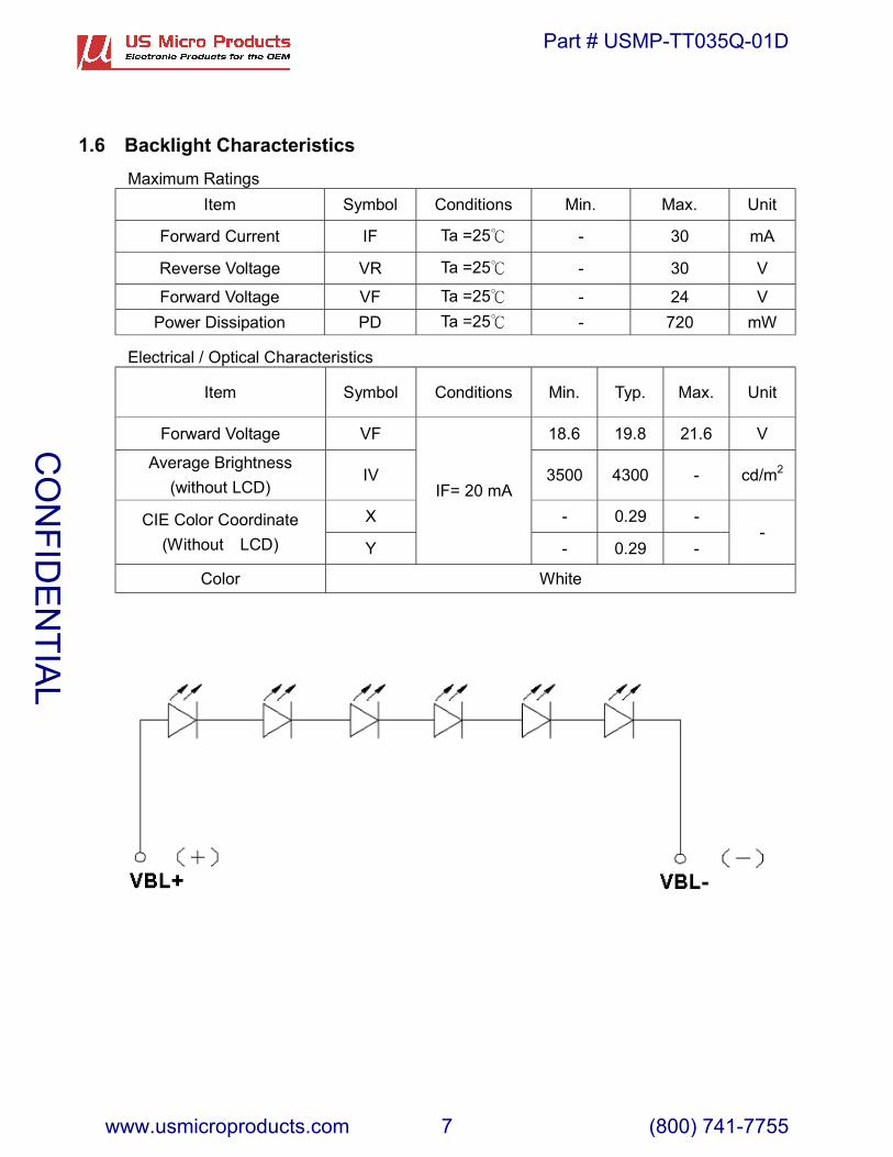
1.6 Backlight CharacteristicsMaximum Ratings
Item Symbol Conditions Min. Max. Unit
Forward Current IF Ta =25� - 30 mA
Reverse Voltage VR Ta =25� - 30 V
Forward Voltage VF Ta =25� - 24 VPower Dissipation PD Ta =25� - 720 mW
Electrical / Optical Characteristics
Item Symbol Conditions Min. Typ. Max. Unit
Forward Voltage VF 18.6 19.8 21.6 V
Average Brightness(without LCD)
IV 3500 4300 - cd/m2
X - 0.29 -CIE Color Coordinate(Without LCD) Y
IF= 20 mA
- 0.29 --
Color White
CO
NFID
EN
TIAL
Part # USMP-TT035Q-01D
www.usmicroproducts.com 7 (800) 741-7755

2. MODULE STRUCTURE2.1 Counter Drawing
2.1.1 LCM Mechanical Diagram
* See Appendix
2.1.2 Block Diagram
CO
NFID
EN
TIAL
Part # USMP-TT035Q-01D
www.usmicroproducts.com 8 (800) 741-7755
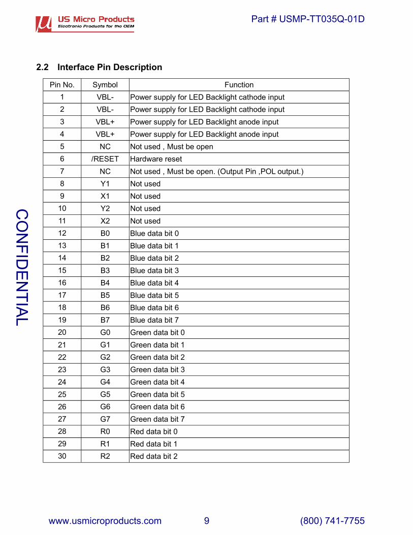
2.2 Interface Pin Description
Pin No. Symbol Function1 VBL- Power supply for LED Backlight cathode input2 VBL- Power supply for LED Backlight cathode input3 VBL+ Power supply for LED Backlight anode input 4 VBL+ Power supply for LED Backlight anode input 5 NC Not used , Must be open6 /RESET Hardware reset7 NC Not used , Must be open. (Output Pin ,POL output.)8 Y1 Not used9 X1 Not used10 Y2 Not used11 X2 Not used12 B0 Blue data bit 0 13 B1 Blue data bit 1 14 B2 Blue data bit 2 15 B3 Blue data bit 3 16 B4 Blue data bit 4 17 B5 Blue data bit 5 18 B6 Blue data bit 6 19 B7 Blue data bit 7 20 G0 Green data bit 0 21 G1 Green data bit 1 22 G2 Green data bit 2 23 G3 Green data bit 3 24 G4 Green data bit 4 25 G5 Green data bit 5 26 G6 Green data bit 6 27 G7 Green data bit 7 28 R0 Red data bit 0 29 R1 Red data bit 1 30 R2 Red data bit 2
CO
NFID
EN
TIAL
Part # USMP-TT035Q-01D
www.usmicroproducts.com 9 (800) 741-7755

31 R3 Red data bit 3 32 R4 Red data bit 4 33 R5 Red data bit 5 34 R6 Red data bit 6 35 R7 Red data bit 7 36 HSYNC Horizontal sync input37 VSYNC Vertical sync input38 DOTCLK Dot data clock39 VDDIO Digital power40 VDDIO Digital power41 VDDIO Digital power42 VDDIO Digital power43 SPENA Serial port data enable signal44 NC Not used , Must be open45 NC Not used , Must be open (Output Pin ,VGL ,Gate off power.)46 NC Not used , Must be open47 NC Not used , Must be open (Output Pin ,VGH, Gate on power.)
48 SHUT
Display shut down pin to put the driver into sleep mode. A sharpfalling edge must be provided to such pin when IC power on.Internal pull low.- Connect to VDDIO for sleep mode- Connect to VSS for normal operating mode(Refer to Power Up Sequence)
49 SPCLK Serial data clock50 SPDAT Serial data51 NC Not used , Must be open (Output Pin ,VCOM power.)52 ENB Data enable control53 VSS Ground54 VSS Ground
CO
NFID
EN
TIAL
Part # USMP-TT035Q-01D
www.usmicroproducts.com 10 (800) 741-7755

2.3 Timing Characteristics
Note�The interface of this module can drive by digital 24-bit data.
CO
NFID
EN
TIAL
Part # USMP-TT035Q-01D
www.usmicroproducts.com 11 (800) 741-7755
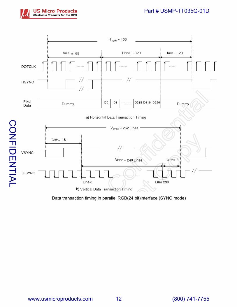
Data transaction timing in parallel RGB(24 bit)interface (SYNC mode)
CO
NFID
EN
TIAL
Part # USMP-TT035Q-01D
www.usmicroproducts.com 12 (800) 741-7755

2.4 Power Sequence2.4.1 Power up sequence
VDDIO
/RESET
CO
NFID
EN
TIAL
Part # USMP-TT035Q-01D
www.usmicroproducts.com 13 (800) 741-7755
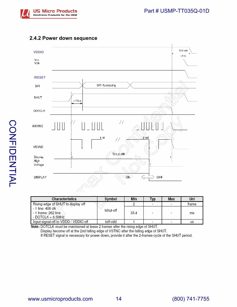
2.4.2 Power down sequence
/RESET
VDDIO
CO
NFID
EN
TIAL
Part # USMP-TT035Q-01D
www.usmicroproducts.com 14 (800) 741-7755
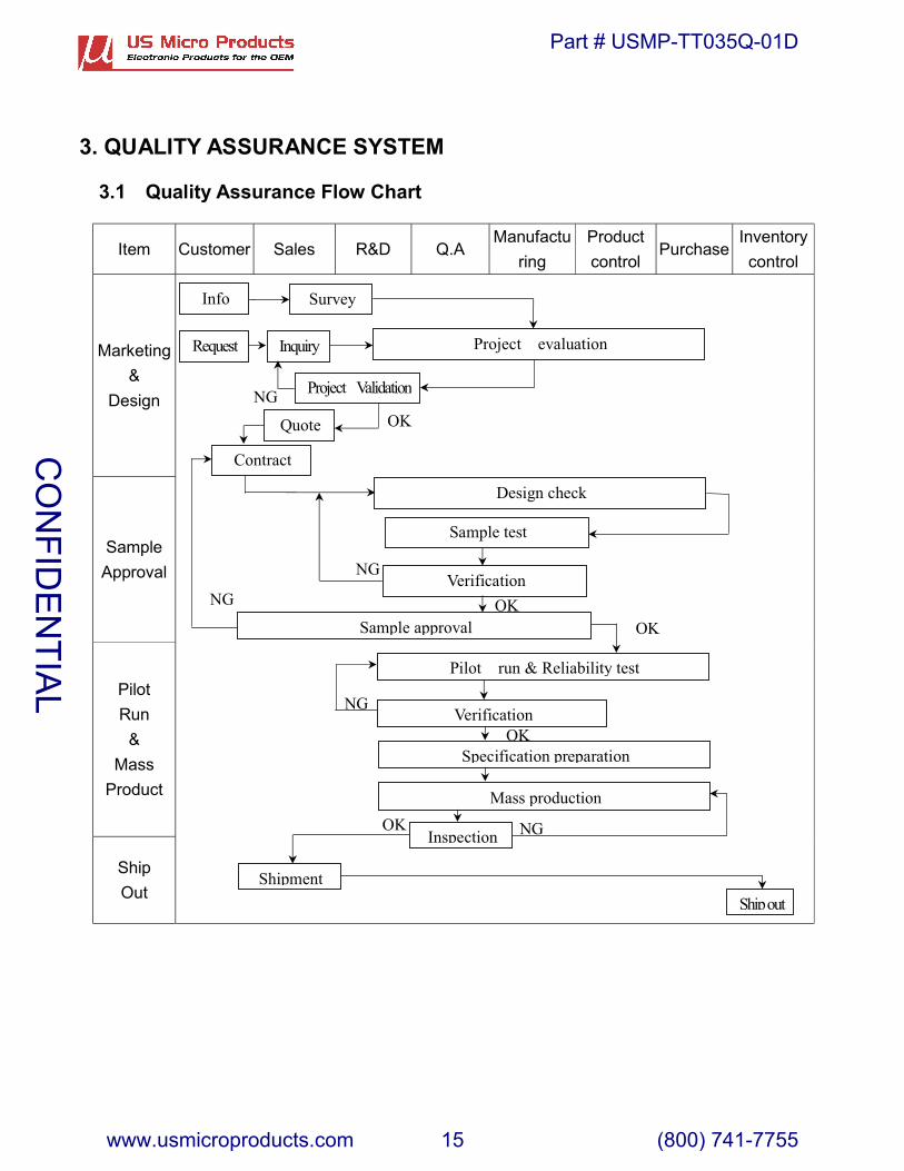
3. QUALITY ASSURANCE SYSTEM
3.1 Quality Assurance Flow Chart
Item Customer Sales R&D Q.AManufactu
ringProductcontrol
PurchaseInventorycontrol
Marketing&
Design
SampleApproval
PilotRun
&Mass
Product
ShipOut
OK
Request
Info Survey
Inquiry Project evaluation
Project Validation
Quote OKNG
Contract
Design check
Sample test
Verification
Sample approval
NG
NG
Pilot run & Reliability test
Verification
Specification preparationOK
Mass production
Inspection NGOK
Shipment
NG
Ship out
OK
CO
NFID
EN
TIAL
Part # USMP-TT035Q-01D
www.usmicroproducts.com 15 (800) 741-7755
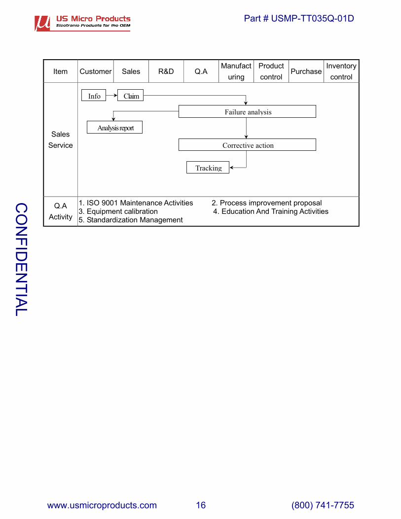
Item Customer Sales R&D Q.AManufact
uringProductcontrol
PurchaseInventorycontrol
SalesService
Q.AActivity
1. ISO 9001 Maintenance Activities 2. Process improvement proposal3. Equipment calibration 4. Education And Training Activities5. Standardization Management
Info Claim
Failure analysis
Corrective action
Tracking
Analysis report
CO
NFID
EN
TIAL
Part # USMP-TT035Q-01D
www.usmicroproducts.com 16 (800) 741-7755

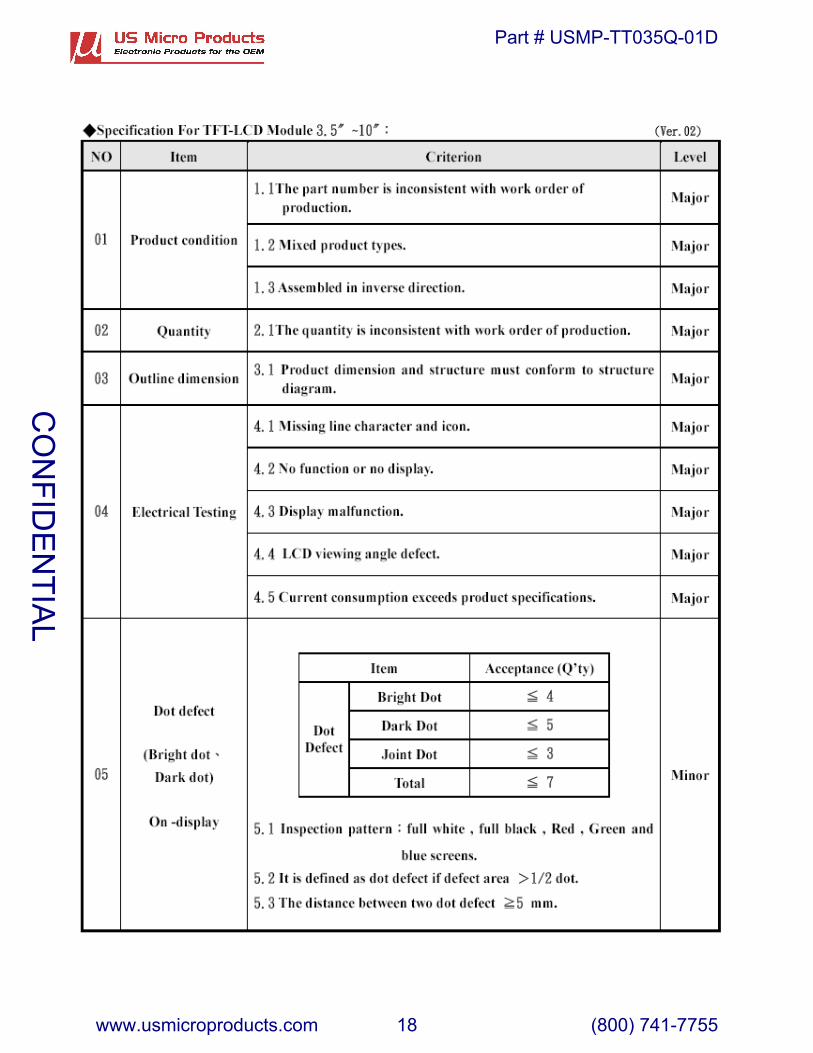
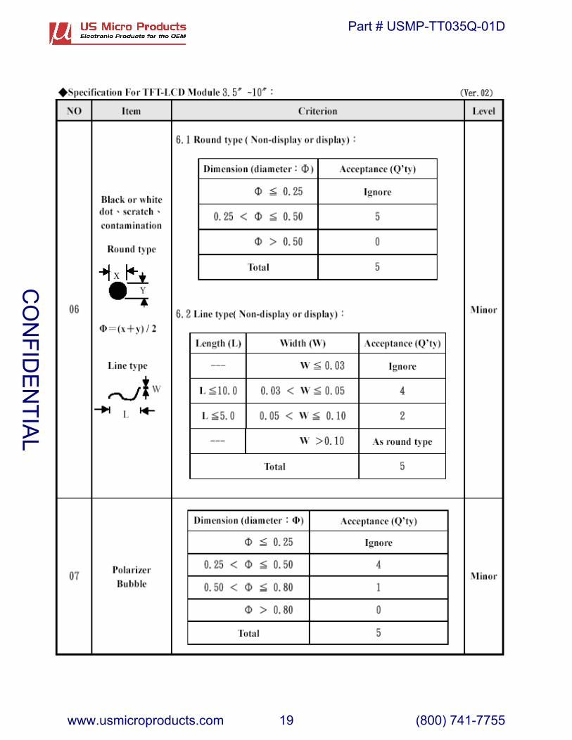
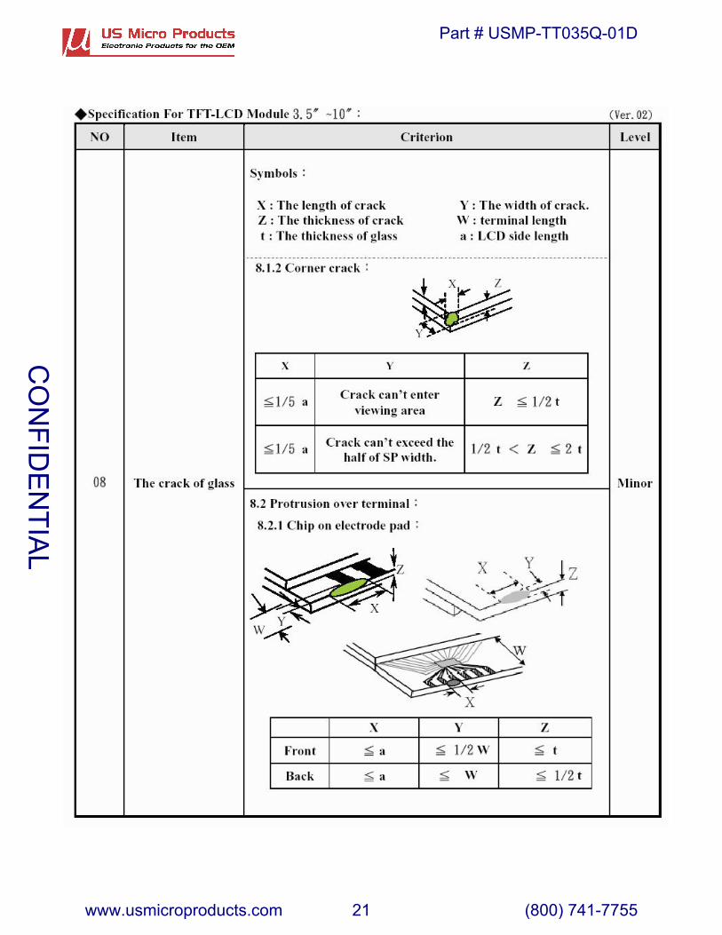
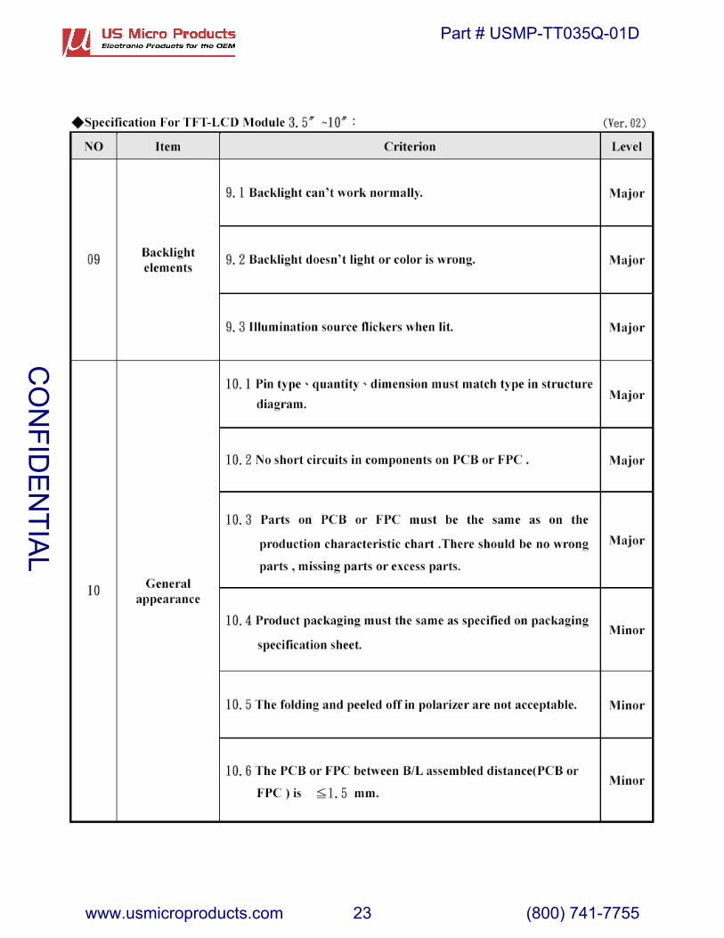
3.2 Inspection Specification
CO
NFID
EN
TIAL
Part # USMP-TT035Q-01D
www.usmicroproducts.com 17 (800) 741-7755
CO
NFID
EN
TIAL
Part # USMP-TT035Q-01D
www.usmicroproducts.com 18 (800) 741-7755
CO
NFID
EN
TIAL
Part # USMP-TT035Q-01D
www.usmicroproducts.com 19 (800) 741-7755

CO
NFID
EN
TIAL
Part # USMP-TT035Q-01D
www.usmicroproducts.com 20 (800) 741-7755
CO
NFID
EN
TIAL
Part # USMP-TT035Q-01D
www.usmicroproducts.com 21 (800) 741-7755

CO
NFID
EN
TIAL
Part # USMP-TT035Q-01D
www.usmicroproducts.com 22 (800) 741-7755
CO
NFID
EN
TIAL
Part # USMP-TT035Q-01D
www.usmicroproducts.com 23 (800) 741-7755
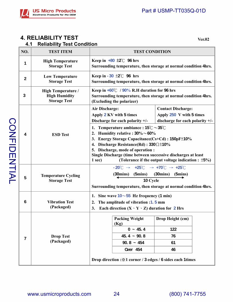
4. RELIABILITY TEST4.1 Reliability Test Condition
NO. TEST ITEM TEST CONDITION
1 High TemperatureStorage Test
Keep in +80 ��2� 96 hrs Surrounding temperature, then storage at normal condition 4hrs.
2 Low TemperatureStorage Test
Keep in -30 �2� 96 hrsSurrounding temperature, then storage at normal condition 4hrs.
3High Temperature /
High HumidityStorage Test
Keep in +60� / 90% R.H duration for 96 hrsSurrounding temperature, then storage at normal condition 4hrs.(Excluding the polarizer)
Air Discharge:Apply 2 KV with 5 timesDischarge for each polarity +/-
Contact Discharge:Apply 250 V with 5 timesdischarge for each polarity +/-
4 ESD Test1. Temperature ambiance : 15��35�2. Humidity relative : 30%�60%3. Energy Storage Capacitance(Cs+Cd) : 150pF�10%4. Discharge Resistance(Rd) : 330��10%5. Discharge, mode of operation :Single Discharge (time between successive discharges at least1 sec) (Tolerance if the output voltage indication : �5%)
5 Temperature CyclingStorage Test
-20� � +25� � +70� � +25�(30mins) (5mins) (30mins) (5mins)
10 CycleSurrounding temperature, then storage at normal condition 4hrs.
6 Vibration Test(Packaged)
1. Sine wave 10�55 Hz frequency (1 min)2. The amplitude of vibration :1.5 mm3. Each direction (X�Y�Z) duration for 2 Hrs
7 Drop Test(Packaged)
Drop direction :1 corner / 3 edges / 6 sides each 1times
Packing Weight(Kg)
Drop Height (cm)
0 ~ 45.4 12245.4 ~ 90.8 7690.8 ~ 454 61Over 454 46
Ver.02
CO
NFID
EN
TIAL
Part # USMP-TT035Q-01D
www.usmicroproducts.com 24 (800) 741-7755
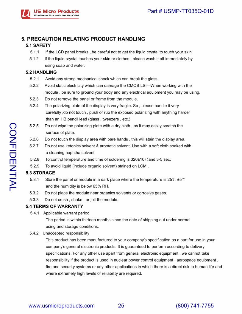
5. PRECAUTION RELATING PRODUCT HANDLING5.1 SAFETY
5.1.1 If the LCD panel breaks , be careful not to get the liquid crystal to touch your skin.5.1.2 If the liquid crystal touches your skin or clothes , please wash it off immediately by
using soap and water.
5.2 HANDLING5.2.1 Avoid any strong mechanical shock which can break the glass.5.2.2 Avoid static electricity which can damage the CMOS LSI—When working with the
module , be sure to ground your body and any electrical equipment you may be using.5.2.3 Do not remove the panel or frame from the module.5.2.4 The polarizing plate of the display is very fragile. So , please handle it very
carefully ,do not touch , push or rub the exposed polarizing with anything harder than an HB pencil lead (glass , tweezers , etc.)
5.2.5 Do not wipe the polarizing plate with a dry cloth , as it may easily scratch thesurface of plate.
5.2.6 Do not touch the display area with bare hands , this will stain the display area.5.2.7 Do not use ketonics solvent & aromatic solvent. Use with a soft cloth soaked with
a cleaning naphtha solvent.5.2.8 To control temperature and time of soldering is 320±10 and 3� -5 sec.5.2.9 To avoid liquid (include organic solvent) stained on LCM .
5.3 STORAGE5.3.1 Store the panel or module in a dark place where the temperature is 25 ±5� �
and the humidity is below 65% RH.5.3.2 Do not place the module near organics solvents or corrosive gases.5.3.3 Do not crush , shake , or jolt the module.
5.4 TERMS OF WARRANTY5.4.1 Applicable warrant period
The period is within thirteen months since the date of shipping out under normalusing and storage conditions.
5.4.2 Unaccepted responsibilityThis product has been manufactured to your company’s specification as a part for use in yourcompany’s general electronic products. It is guaranteed to perform according to deliveryspecifications. For any other use apart from general electronic equipment , we cannot takeresponsibility if the product is used in nuclear power control equipment , aerospace equipment , fire and security systems or any other applications in which there is a direct risk to human life andwhere extremely high levels of reliability are required.
CO
NFID
EN
TIAL
Part # USMP-TT035Q-01D
www.usmicroproducts.com 25 (800) 741-7755
6207
Bee
Cav
es R
d.,
Ste.
330
; Au
stin
, TX
787
46 U
SATe
l: (8
00) 7
41-7
755,
sal
es@
usm
icro
pro
du
cts.
com
ww
w.u
smic
rop
rod
uct
s.co
m
CO
NFID
EN
TIAL
Part # USMP-TT035Q-01D
www.usmicroproducts.com 26 (800) 741-7755
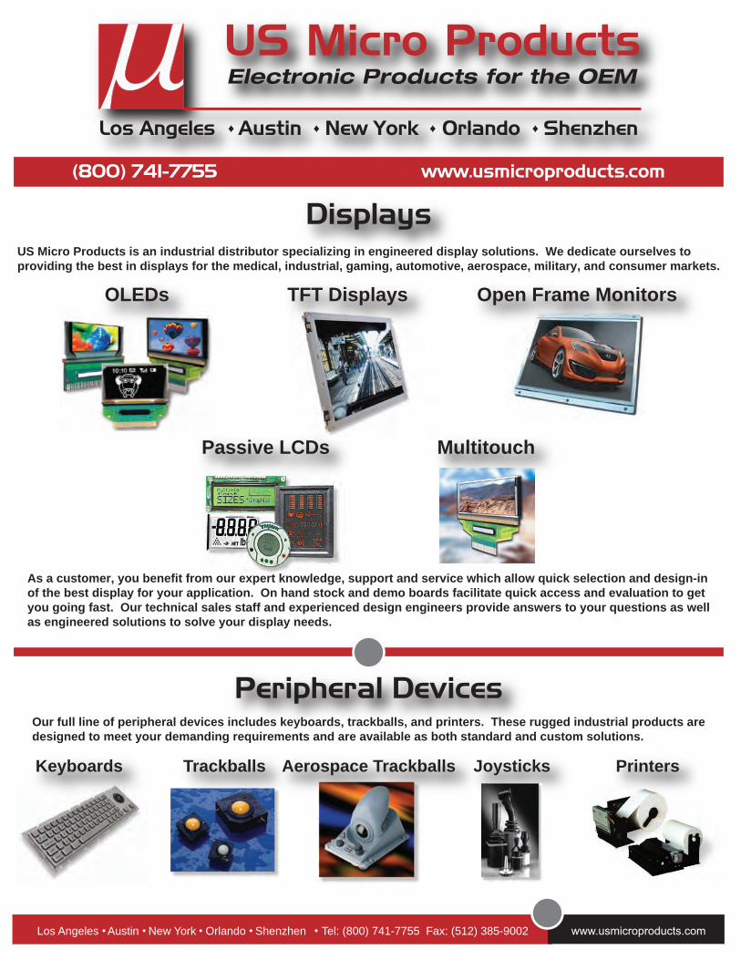
Los Angeles Austin New York Orlando Shenzhen ♦ ♦ ♦ ♦
PrintersKeyboards JoysticksTrackballs Aerospace Trackballs
Los Angeles Austin New York Orlando Shenzhen Tel: (800) 741-7755 Fax: (512) 385-9002
OLEDs TFT Displays Open Frame Monitors
Passive LCDs Multitouch
(800) 741-7755 www.usmicroproducts.com
Displays
Peripheral Devices
US Micro Products is an industrial distributor specializing in engineered display solutions. We dedicate ourselves toproviding the best in displays for the medical, industrial, gaming, automotive, aerospace, military, and consumer markets.
Our full line of peripheral devices includes keyboards, trackballs, and printers. These rugged industrial products aredesigned to meet your demanding requirements and are available as both standard and custom solutions.
As a customer, you benefit from our expert knowledge, support and service which allow quick selection and design-inof the best display for your application. On hand stock and demo boards facilitate quick access and evaluation to getyou going fast. Our technical sales staff and experienced design engineers provide answers to your questions as wellas engineered solutions to solve your display needs.