Embed Size (px)
Citation preview
Copyright University of Strathclyde, prepared by FK Crawley for IChemE 74
Part D
DESIGN FOR SAFE OPERATION AND SAFE OPERATION TECHNIQUES
Some of this is a repeat of the Part B on Identification. The topics have two homes so it is better to repeat them rather than miss them.
D 1 Introduction and Background
It is not possible to eliminate all hazards to personnel/property however much effort is put into the task but there will always be a chance that a hazard will occur.
The very nature of hazards is that they are a complex interplay of causes (reverse of Defence in Depth). No firm rules can be laid down and so this part, on design features, is presented in general terms so that you will be able to appreciate the application of techniques and solutions to particular processes. These are just some of the hardware “Defences” in Defence in Depth.
In general, the effects of hazards can be divided into the following categories:
• Pollution (including noise)
• Chemical Reactions and Reactivity
• Toxicity (including Asphyxiation and long term effects)
• Mechanical Failure
• Corrosion
• Nuclear Radiation (where appropriate)
• The small event leading to a larger event (Domino Effect)
• Fire
• Explosion
The hazards may affect the following:-
1. The environment (land, water, air)
2. Company employees within, or the public outside the site
3. Plant equipment, storage facilities, offices, warehouses, laboratories, etc.
4. Property outside the site
Copyright University of Strathclyde, prepared by FK Crawley for IChemE 75
5. The company cash flow (by loss of revenue, replacement of damaged equipment and/or payment of claims for damages)
Commonly hazards are controlled by:-
1. Elimination
2. Containment
3. Reduced Frequency
4. Reduced Effect
5. 'First Aid' Measures
In some cases the hazard will be dealt with by a hardware or engineering solution and in others by a management or "software" procedure. Generally hardware solutions are used during the design phases of a project and software procedures during the start-up and operating phases of the project. The relative costs and ease of implementation will also affect the choice of solution. While it is possible to specify the performance of a hardware protective system and test the hardware to determine if the desired performance is achieved, it is less easy to assess the performance of software systems and to determine the performance of the software (procedures.) Procedures tend to become degraded with time and it is often difficult to assess the level of degradation other by an Audit (See Advanced Management Systems Part F.)
As accidents cannot be totally eliminated you must aim to reduce them to an acceptably low level. Further, you should recognise that reducing one risk may increase another and the final result must be a balance of risks. For example, a solution which reduces human risk may increase the environmental risk and the designer must take into account this delicate balance. The total risk to the environment, humans, plant fabric and cash flow must be acceptable both to the company and to the Regulatory Authorities.
The “prevention” of incidents leading to injury, health problems and pollution of the environment must therefore start at the design stage. Once design faults are incorporated it is very much a case of the use of palliatives. This is not in the spirit of “inherently safer”. There are a number of tried and tested design procedures which have been applied and it is appropriate to put these into one condensed Part. These have been selected and probably represent a small percentage of the possible list of design techniques or tools. The order given is not in priority.
D 2 Hazard Studies Design Phases and Details
The various design phases were introduced in Part A as it is a corner stone of procedures, design and others such as maintenance. It is now necessary to add a little more detail; the numbering is as in Part A as this has stood the test of time and Engineers can relate to this numbering.
Study 0 Inherency
Inherency is that concept that challenges the accepted and asks “Is there a better way?” The objective is to make the design safer by the very design. Various strategies can be adopted and are triggered by “guide words” as given. See Part D 13 for examples.
Copyright University of Strathclyde, prepared by FK Crawley for IChemE 76
Intensify
Concentrate the process in a smaller, higher pressure reactor and reduce the working inventory or total leak potential. An example might be a high pressure catalytic reactor which is significantly smaller than the conventional low pressure reactor. Another might be the use of a linear reactor instead of a continuously stirred back mixed reactor. Another might be the use of specialised equipment which has by the very nature of the design a very low inventory, some of the modern compact heat exchangers would fit into this heading. The end point is that while the peak out flow rate from a hole (loss of containment – LOC) may be higher the total out flow will be significantly lower.
Attenuate
Reduce the working pressure/temperature such that the leak rate – should it occur – is less or less likely to ignite/vaporise. An example might be the use of refrigerated storage of cryogenics instead of pressurised storage. Once again the use of a catalyst lends to inherency.
Substitute
Change the process route using chemicals which are safer or which do not produce hazardous by-products or intermediates. Steam is inherently safer than hot oil. Steam heating may be inherently safer than electrical heating in that it has a self limiting upper temperature limit.
Simplify
This is self evident.
Getting it Right First Time
Avoid the need for last minute change or even recognising the whole spectrum of conditions which may apply to choosing the correct materials for fabrication and the choice of design pressure for equipment. It can also mean “de-clutter” the process and avoid a surfeit of “add-on safety features” which do little for SHE or efficiency but create operational problems.
Change
While the concept of change is simple it does require a bit of thought! Consider the “change” in a layout such as to segregate flammable materials from sources of ignition or the positioning of a valve such that access is enhanced – the layout or access is then inherently safer. Change may involve a new process if the environmental implications were adverse. “Change” is simple but finding the solution is less so!
Eliminate
This is more a statement of the obvious. Consider the design pressures; can you eliminate the need for overpressure protection by the selection of the equipment design pressures?
Eliminate and Change look at the same basics problem from different directions.
Second Chance/fails safe
The ability to recover from and to survive an upset or to tolerate the extremes of the operating/upset conditions envelope.
Copyright University of Strathclyde, prepared by FK Crawley for IChemE 77
Capture and recycle.
Capture leakage and rework it. This has application in terms of the environment.
Study 1 Concept - well before sanction
Objective To identify the major problems which have to be overcome before the concept can become a viable project.
End Point The concept should be capable of development into a project
Basically, are there any “show stoppers” which are so insurmountable that it is not worth carrying on with the Project?
The concept requires a fundamental review of all aspects that could stop the development of the project or the process chosen. They need not necessarily be process related but will also address the possible effluents, the source of feedstocks, the source of water, the availability of trained staff for operation and maintenance. Finally the site chosen may be “Brown Field” or one that has been used before and may require remedial treatment. Even worse it may be on recovered land and require consolidation or piling.
The chemistry and the separation processes will require serious review as will the reaction process to make the product. During this phase the major issues must be highlighted with potential solutions. If there are no solutions it is likely that the project will fail at a later stage.
Study 2 Concept Development or Front End Engineering Design
During the conceptual design there is an attempt to identify those problems which must be solved before there is a viable project. You must be satisfied that there is a safe, reliable process with minimal environmental impact. Shortly after conceptual design it will also be necessary to satisfy the regulatory authorities and local planning authorities of its safety. This may require a “Safety Case”. If all the significant hazards are not identified during this phase, redesign may be expensive, the project may be delayed and the extra design features may make the project non viable.
Chemical, Physical and Toxicological Properties
Do you understand the chemistry of the process in particular the thermal stability of the reactants and reactions? Is there a potential for an exothermic reaction of the reactants at elevated temperature? Under what conditions may the reaction become thermally unstable and “runaway”? In addition to analysing the basic chemical reaction consideration you should also consider side reactions and reactions between products, by-products and intermediate products. These should be examined over a wide range of pressures, temperatures, concentrations and residence times. The extremes of conditions should be realistic - the maximum temperature could be that of the steam jacket, the maximum pressure could be that of the relief valve lift pressure plus accumulated pressure. See Part D 4 Chemical Reactors.
Chemical processes which must be considered to be potentially hazardous are those which:-
• Involve fast reactions
• Have exothermic reactions
Copyright University of Strathclyde, prepared by FK Crawley for IChemE 78
• Contain chemicals which react vigorously with common contaminants such as rust or water or by-products
• Produce exotherms (or may produce exotherms in the possible design temperature range)
• Produce polymers either by intent or accident
• Handle unsaturated hydrocarbons (particularly Acetylene)
• Handle flammable fluids at elevated temperature and pressure
• Involve oxidation or hydrogenation processes
• Handle or produce thermally sensitive feed stock, products or by-products
• Handle acids or alkalis
• Handle toxic compounds
• Produce dusts or sprays
• Have high stored pressure energy
This work can be facilitated by examining databases, both chemical and hazard, and world wide experience. From this it should be possible to draw up the physical, chemical, and toxicological properties of the materials processed including feedstock, product/by-product intermediate products and catalysts. (MHDS) Remember to include additives used for water treatment, boiler feed treatment, catalysts and other treatment agents such as used for anti-corrosion. Suitable reference sources are manufacturers' data sheets, and databases. It may be necessary to initiate investigations to determine the properties of intermediate and by-product which may not have been studied in detail but have been identified in the laboratory or the Pilot Plant. The properties of the materials should include not only short term but also the long-term effects on both humans and the environment.
Consideration should be given to the inadvertent mixing of incompatible fluids in drains or effluent systems. This has been a safety issue on many plants. It may be necessary to have segregated drains which can be handled according to the properties of the materials.
It is worth noting that historically one of the major sources of hazard has been the lack of knowledge of both the nature of the by-products and their properties, the classic example being Seveso.
Effluent
Estimates of the types of effluent that might be handled; the quantities and concentrations should be drawn up. Remember that noise and smell are nuisance effluents. Consider how you are to handle abnormal materials and amount and nature of the off-specification “products” produced under upset conditions such as commissioning, start-up and production upset when off specification materials are inevitable. Means for disposing of these effluents should be outlined and may include:-
• Dilution (within consent limits)
• Neutralisation or chemical destruction
Copyright University of Strathclyde, prepared by FK Crawley for IChemE 79
• Bio treatment
• Combustion in a flare or incinerator - (consider also the effects of the by-products of a combustion)
• Regeneration/Recycling. (This has a limited life as it can only take place while there is storage available. Sometimes it is possible to re-run or recycle small amount at a time and so to recover the products.)
• Reduction/Attenuation in the case of noise
Consider in addition the effects of fugitive emissions from tank vents and simple process leaks. Could these be unsafe or a nuisance either to the employee or the public?
Feedstock/Product Handling
An assessment should be made of the type of storage of feedstock, products and intermediates. Consideration should be given to how the materials will be transported to/from the site and the risks associated with the transport. In general transport by a pipeline is safer than transport by road/rail and results in smaller buffer storage.
Layout (See also D 5 for more detail)
Layout of the plant is at best a form of compromise. The plant will inevitably have neighbours or the public and all attempts must be made to arrange the layout which is both visually acceptable, produces the minimum of disturbance by light, noise and odour and has the lowest risk to the public. This is a difficult task! Consider the following-
Segregate process furnaces with open combustion, from adjacent sources of flammable fluids.
Segregate large inventories of flammable fluids by means of fire breaks and containment bunds?
Arrange the layout such that large volumes of flammable and toxic fluids can be located as far away from the public, offices and control rooms as is practicable
Arrange the layout so that noisy equipment such as compressors are located as far as is practicable from the public.
Likewise sources of visual disturbance such as flare stacks and tall equipment like distillation columns. Is it better to arrange the column as two sections of half the height? (This may be in conflict with inherency!)
Arrange the layout such that sources of malodorous effluent are located as far from the public as is practicable.
Can inventories be reduced at study 0 by the “inherently safer” approach?
Note that fire breaks or breaks between reactors and process equipment can be created by interposing safe (non combustible) services such as instrument air systems or road and access ways.
Copyright University of Strathclyde, prepared by FK Crawley for IChemE 80
Finally, but not least, the layout should also take into account the prevailing wind direction and atmospheric conditions. This will affect the way toxic and flammable fumes could spread across and outside the site.
Process Equipment
Are there any unusual features which may create problems in the future or which must be eliminated during the design phase of the project? Typical problem areas could be:
• Exotic materials of construction which require special means of hydro test.
• Arduous shaft sealing duties - for example slurries or high speed shafts
• Novel processing equipment which has not been proven in the field
• Operating in a condition close to a phase change – boiling or freezing when special precautions such as heat tracing to avoid freezing may be required.
• Operations which require extremes of cleanliness not only cleanliness from dirt but also from water should it freeze. (Traces of oxygen can produce stress corrosion cracking of Ammonia storage vessels).
Consideration should also be given to the following:-
The potential for damage to pipelines and essential services through fire, impact or corrosion. This could be internal due to the process or external due to wet lagging.
The access for emergency services for rescue of the injured. The access for the Fire engines to various parts of the site and how the fire engines can reach the site may be a complex study.)
Two access routes are essential.
Can the local topography affect the way in which fires may spread? Look at the topography and ask: “Can a fire or toxic gas flow downhill to vulnerable equipment?
Risk Assessment and Safety Cases
As a result of the risk assessment and the Safety Case it may be necessary to change the process or layout. It may be that the “protective systems”, active or passive, have to be enhanced. (Active refers to Shutdown Systems (See Part D 8) and Passive refers to Fire Protection by “fireproofing lagging” and the like). The layout including the location of major inventories may have to be changed. It is self evident that the Safety Case hurdle has to be overcome before construction can start!
If the performance of the Shut down System (SIS) is left till the Detail Design Stage there is the possibility of project delays as the design is rethought and equipment ordered.
Study 3 Detailed Design
Whereas the conceptual design phase gives a general outline of what the process system will look like there are no firm decisions made. In the design phase you will make many decisions which finalise the plant design. Most of these concern equipment which, once ordered, is not readily replaced or modified.
Copyright University of Strathclyde, prepared by FK Crawley for IChemE 81
Pressure Vessels must be designed and tested to recognise design standards and are also subject to legal requirements – these vary round the world. They must be designed correctly, tested correctly, inspected correctly and operated correctly.
The design of seals on Pumps/Compressors requires careful analysis so as to minimise harmful leakage of toxic, flammable, corrosive or other harmful fluids. Where appropriate the leakage should be captured and recycled.
Piping must be carefully designed for stresses imposed on it by both internal pressure as well as thermal growth/contraction. It must be carefully designed for reaction forces at bends and constrained to move only in one axis at any location. The stress analysis is complex and often uses sophisticated computer programmes.
The detailed design phase should not only address the plant safety with respect to the list given in the introduction - it should also address access, tripping, falling and other operational hazards. Access will involve safe removal of equipment.
During conceptual design the problems associated with the chemical reactions and/or processing system should have identified. The toxicological and physical properties of the reactants products/by-products intermediate products and catalysts should also have been determined and hazardous properties sheets been drawn up. The likely disposal routes for effluents should have identified and the required site and plot dimensions should have been specified.
Part B identified typical procedures which should be carried out to identify and quantify hazards. When P & IDs have been completed Hazard and Operability studies should be carried out and any necessary changes incorporated. When pipe routes are defined, Relief and Blow down studies should be carried out to ensure that the relieving capacities and pipe sizes (pressure drops) are adequate for the largest foreseeable demands and combination of relief loads.
The following phases have been analysed in Part A:
4 Construction
5 Prestart-up
6 Post Start-up
7 Demolition
It is important that Demolition is considered at all stages of the design
D 3 General Design Principles
The design must be robust and capable of handling both over-pressure and under-pressure conditions and temperature excursions where appropriate. The design should be such as to ensure a secure containment system. The design MUST use internationally recognised codes/standards for equipment, likewise piping.
“Mix and Match” is NOT an acceptable design philosophy.
Copyright University of Strathclyde, prepared by FK Crawley for IChemE 82
If the process handles flammable materials the sources of ignition must be kept to a minimum and the specification of the electrical equipment must be appropriate to the gases (see later D 7) and the likely occurrence of flammable vapour. It should also be tolerant of small fires and be so designed as to minimise the frequency of large fires and/or explosions.
In the case of corrosive fluids the design should be tolerant of corrosion both inside and outside the containment. This means that leakage of corrosive materials must not damage its support or the support of another system.
The design should be such as to avoid one event setting off another larger event – the “domino effect”. A simple example would be a power failure which leads to a runaway reaction resulting in an explosion; another could be corrosion which results in structural collapse.
Safe design can be achieved by the use of a number of tried and tested techniques which will be expanded upon in separate discrete sections.
D 4 Chemical Reactors
See the notes on stability in section B 1.1 Reactors come in many forms: 1a Exothermic – heat given out by the reaction 1b Endothermic – heat consumed by the reaction 2a Solid bed – usually a catalyst 2b Back-mixed – internally mixed (usually liquid phase) 3a Liquid phase 3b Gas phase
The combinations of types 1, 2 and 3 give 8 possible types.
Exothermic, Solid Bed, Liquid Phase Endothermic, Solid Bed, Liquid Phase Exothermic, Back Mixed, Liquid Phase etc.
In general the endothermic reactions are not as issue as they “die” if heat is not added. There may be some issues about by-products under these circumstances.
The main issue is with EXOTHERMIC reactions. In these heat is generated and if not controlled or removed the reactants warm up and follow the ARRHENIUS LAW so the reaction accelerates. It is not difficult to see that the loss of temperature control of the reactor could (and does) result in an EXPLOSIVE REACTION.
It follows therefore that integrity (reliability) of the temperature control is fundamental to both operability and safety. Heat exchangers used to cool the reactor should be oversized to account for
possible fouling and likewise pumps due to fouling or wear and tear.
The reliability has to be assessed as part of the process safety; a weak link could be disastrous. Typical exothermic reactions involve hydrogenation and oxidation but polymerisation reactions have exothermic
Copyright University of Strathclyde, prepared by FK Crawley for IChemE 83
potential. Increasingly more fine chemical processes are being used with small scale batch reactors with elegant chemistry which also have the potential for exothermic reactions.
There are some possible twists that require consideration with catalysts. Some catalysts are very selective over a limited temperature band and become non selective outside that band creating adverse by-products which may cause product contamination or reactive by-products. As a generalisation, catalysts also have to be raised to a “critical” temperature before the reaction can take place and if they cool too much the reaction will die or stop. “Critical” is case specific, in the case of the partial combustion of methanol to make formaldehyde it is about 850oC but in others it can be as low as 60oC. Catalysts can also become poisoned by impurities - this can be used to kill a runaway reaction or it may require careful control of the quality of the reactants to avoid poisoning the catalyst.
The safety of a chemical reactor design should be treated on an individual basis. The following hints may find application.
1. Reduce the inventory of reactants and products as far as practicable.
2. Dilute the reactants with an inert fluid (to increase the heat sink) if the reaction is exothermic and fast. This slows the rate of temperature build up – it does not arrest it. Temperature control is still vital. The heat can then be removed by cooling the batch with an internal or external cooler or by allowing the inert fluid to boil and then be returned as liquid from a condenser.
3. In exothermic reactions ensure that there is an excess of cooling capacity - design the cooler (condenser) for the worst possible reactor temperature conditions and if necessary add some extra surface area against internal and external surface fouling or fall off in performance of the recirculation pump(s).
4a. Avoid stagnant flow areas in reactors where catalysts may settle out (particularly in a continuous back mixed liquid phase reactor) or where vigorous side reactions may be initiated in liquid phase reactions. Enhanced mixing may be required following flow modelling.
4b. Ensure vigorous vertical and radial mixing in liquid phase reactions.
4c. Locate the inlet branches on the reactor such as to assist the mixing process. This may require a detailed analysis of the fluid dynamics in the reactor. (Model tests have simulated complex flow regimes within reactors, including a “switching” from one flow regime to another.)
5. Install a coolant quench which will flood the reactor with a cold inert fluid, so cooling the reaction below an initiating temperature or dump the reactants into a quench tank. (This is used in the nitration of glycerine.)
6. Install a catalyst kill system.
7. Carefully sequence and control the rate of addition of the reactants (and catalysts if applicable) into the reactor to avoid high rate of temperature rise conditions (a variant of 2).
8. Monitor the temperature of the bulk of reactor at many points to locate "hot spots" particularly on fixed bed exothermic reactors.
9. Monitor the reactor for deviations in level, temperature, flow, pressure, catalysts, imbalance in reactant flows and abnormal residence times.
Copyright University of Strathclyde, prepared by FK Crawley for IChemE 84
10. Monitor the feed reactant qualities to determine if abnormal adverse impurities are present.
11. Monitor the reactor effluents for evidence of adverse chemical reactions - for example oxides of carbon in hydrocarbon oxidation processes.
12. In the ultimate case it may be appropriate to install bursting discs which rupture and depressurise the reaction process to a safe disposal point. This is the Design Institute Emergency Relief Systems (DIERS) approach. The rate of reaction is reduced by the adiabatic expansion of the reactor contents and some reactants are ejected in the venting process where they are recovered.
This is a specialised design process.
It has to be analysed and assessed by the hazard studies 1 and 2.
The list is not complete but is meant to be indicative of the range of potential controls which may be required.
The problems with reactors and therefore many – these are just some:-
Runaway – loss of cooling Channelling and hot spots By-product formation if operated outside closely defined conditions Reactant slippage (incomplete conversion) Catalyst Poisoning Explosive decomposition of reactants/products
The monitoring and control of the reactor is fundamental and special shutdown features are imperative to avoid hazardous conditions. Shutdowns could involve arresting the feed of one of the reactants, dumping the reactants, adding a “kill” reagent to arrest the reaction, over sizing coolers to give adequate safety margins, depressurise the reactor to reduce the reaction rate. There are no rules only a series of strategies developed from the knowledge of the reaction, its by-products and the catalyst used.
The objective of the design must be to prevent an untoward event and, if it cannot be totally prevented, you should reduce it to an acceptable magnitude and frequency.
It follows that there has to be a detailed understanding of the reaction characteristics as well as the catalyst characteristics for efficient and safe operation.
This requires a detailed dialogue between the Chemist and the Chemical Engineer.
The following are some historic problems which have occurred:-
Seveso
In this reaction no harmful by-products were expected but it was believed that superheated steam in the steam heating coil created a hot spot. The reaction was generally endothermic but the reaction which produced dioxin was exothermic and once initiated on the hot spot it could not be controlled. (LPB 104)
Nitration of Glycerine
Copyright University of Strathclyde, prepared by FK Crawley for IChemE 85
This reaction is generally a slow exothermic reaction, which is controlled by cooling. If the temperature rises the reaction becomes more vigorous, the Arrhenius equation shows this. If the heat can not be removed fast enough ultimately the reaction will lead to the detonation of the Nitro-glycerine within the reactor with catastrophic results. The cooler is therefore oversized so as to prevent the thermal runaway and ultimately the reactants are dumped into a sink of cold water which both cools the reactants and dilutes the acids so arresting the reaction.
Acetylene (Ethyne) Hydrogenation
A mixture of acetylene (Ethyne) and Ethylene (Ethene) and ethane is passed over a Palladium Catalyst with Hydrogen. The reaction is exothermic but the flow of hydrogen is controlled at the stoichioimetric amount to convert Ethyne to Ethene. During a process upset or if the reactor temperature exceeds fixed values the Hydrogen flow is stopped. If the hydrogen flow is not stopped and the hydrocarbon flow is stopped the reaction will carry on, eventually leading the hydrogenation of Ethene. The reaction temperature rises and can eventually reach temperatures which initiate decomposition of the Ethene leading to an explosive detonation. As a result a leaking (passing) hydrogen valves can create a reactor explosion and the shut down system and integrity of the isolation of the hydrogen is safety critical.
Hydrocarbon Oxidation
Many synthetic fibres and produced by air oxidation of hydrocarbons. Nylon starts with the air oxidation of liquid Cyclohexane and Terylene starts with the air oxidation of liquid Paraxylene. In general the reaction is self-regulating as the hydrocarbon is in excess in the liquid phase and the air flow is controlled to maintain the correct conversion ratio. If the air flow rises, more heat is produced and more hydrocarbon is vaporised and condensed and returned to the reactor so maintaining the reactor in a stable regime. If the air is not internally mixed there can be localised hot spots at the air inlet pipes which result in the combustion of cyclohexane/paraxylene to produce Carbon Dioxide. This is called “submerged combustion”.
The production of ethylene oxide is a gas phase reaction over a catalyst close to the lower flammable limit. Once again there is the potential for an explosive decomposition of ethylene and/or ethylene oxide so the control of the reaction temperature and oxygen/ethane ratio is critical and involves a complex shutdown system with majority voting (n out of m). (See Part D 8)
Air Oxidation of Ammonia
Nitric Acid is produced by the air oxidation of Ammonia on an exotic metal catalyst at about 1000oC. The Oxygen/Ammonia ratio is just on the lean side of the flammable limit. If the converter is lit at the wrong ratio (ammonia rich) there could be an explosion and if the reaction is incomplete due to low catalyst bed temperatures the Ammonia slip could result in the formation of Ammonium Nitrate. Ammonium Nitrate is potentially explosive!
Bhopal
The full story of Bhopal is confused but the likely cause was the systematic erosion of the safety systems in the storage of a large quantity of methyl isocyanide (MIC). First, the material was contaminated with chloroform (a by-product of the reaction process). Second, a refrigeration system was non-operational (it had broken down and had not been repaired.) Third some pre-warning alarms had not been fitted. Fourth, and this is not totally clear, the evidence indicates that the final link in the chain – a flare or “also known as a thermal oxidiser” was not lit. The initiating event appears to have been the inadvertent introduction of water (Yes! Water!) into the storage. This was the catalyst that initiated the exothermic decomposition of
Copyright University of Strathclyde, prepared by FK Crawley for IChemE 86
the MIC which was then vented through the flare stack. Inherent safety would indicate that the use of the guideword “attenuate” was applied the materials would have been stored at low temperature (as was the intent but the refrigeration unit was not working) but there was another approach namely “reduce the quantity in storage”.
To recap:
The problems with reactors and therefore many – these are just some:-
Runaway – loss of cooling (following the Arrhenius Equation) Channelling and hot spots leading to by-products or loss of conversion
• By-product formation if operated outside closely defined conditions • Reactant slippage (incomplete conversion)
Catalyst Poisoning due to impurities in the feedstock Explosive decomposition of reactants/products
The monitoring and control of the reactor is fundamental and special shutdown features are imperative to avoid hazardous conditions.
Shutdowns could involve:
1. Arresting the feed of one of the reactants 2. Dumping the reactants 3. Adding a “kill” reagent to arrest the reaction 4. Over sizing coolers to give adequate safety margins, 5. Depressurise the reactor to reduce the reaction rate by means of a bursting disc.
There are no rules, only a series of strategies developed from the knowledge of the chemistry of the reaction, its by-products and the catalyst used.
The objective of the design is to prevent an untoward event and, if it cannot be totally prevented, reduce it to an acceptable magnitude and frequency. Many potentially runaway processes are carried out
remotely.
D 5 Layout and Access
Layout involves placing compatible equipment (persons) in different areas from incompatible equipment (persons). Two incompatible pieces will be Fired Heaters and sources of flammable gases/liquids. This is a sensible example as fired heaters would be at variance with Hazardous Area Classification (Part D 7). Another incompatibility may be people and moving equipment such as drive shafts – this means fitting guards.
Other safety-related issues associated with layout are:
Access – maintenance
All equipment which might require maintenance should be accessible by lifting equipment and /or means of transporting if for repair at a workshop or other safe area. Lifting beams or davits should be fitted and withdrawing space defined for heat exchangers or dropping zones for other equipment. These lifting
Copyright University of Strathclyde, prepared by FK Crawley for IChemE 87
systems require to be inspected on routine. Clear access routes for moving large pieces of equipment – such as heat exchangers should be defined and kept clear. Moving loads have the potential for serious impact and possible loss of containment. Loads passing over pressurised equipment are not recommended. (See access human).
In addition, there should be safe access for those working on the equipment; this will involve safe access to valves (for isolation), orientation of valves and safe access to the equipment as well as a safe escape should there be an emergency.
All equipment, which has rotating parts, should be guarded to avoid contact with hands, feet, hair or loose clothing.
All hot metal (and cold metal) should be lagged/shielded from contact by humans. Cold burns hurt as much as hot burns!!!
Access – human
Particular attention must be paid to access. Good access is required for operational, maintenance and emergencies (escape of personnel and access for fire fighting and rescue). This is regrettably not always achieved, as there is a loss of information exchange between design disciplines.
The following are some access problems which need attention during design.
1. Escape routes - It is a general rule that TWO means of access/escape are required; this is not always possible at, say, the top of a distillation column, but for most structures it can be readily arranged.
2. Head clearance.
3. Valve access - should they be fitted vertically or horizontally and should the valve spindle move up or down? Is there an excessive reach or twist of the body needed for access?
4. Position of valve spindles = do they protrude into an access way?
5. Position of ladders and stairways – ladders should not open to a handrail due to the risk of falling over the rail when leaving the safety cage.
6. Adequate means of ventilating vessels before entry - manholes, position of weirs and internals.
7. Space for pulling tube bundles.
8. Routes for equipment removal – pumps, heat exchangers, pressure relief valves and the potential for impact on pressurised equipment.
In the case of processes handling toxic or corrosive fluids it may be desirable to forbid access to certain areas. In this case the design may have to cater for remote valve operation and instruments may have to be located out of the restricted area.
Valves requiring routine operation should not be located in pits or other inaccessible areas.
Other areas where access should be restricted include areas with automatic CO2 fire protection and areas where ignition sources could be present (e.g. analyses houses and switch rooms in process areas).
Copyright University of Strathclyde, prepared by FK Crawley for IChemE 88
In addition to access to/from equipment and potential for injury, consideration must be given to emergency access/escape. Single walkways should be an absolute minimum of 1m and preferably 1.5m wide. Escape routes or routes where injured personnel may require stretchers must be at least 1.5m wide and have sufficient access on landings to turn a stretcher. Headroom in all cases should be at least 2.25m.
The guiding question must be “can I get into and out of the area in an emergency and can I assist an injured person out of the area?”
When entering confined spaces under permit control TWO routes are preferred (or more) for both gas freeing the space and then ventilation, but in some cases this may not be possible due to other design constraints.
Access must also include access/reach to avoid back injury, so the location of valves, instruments and access structures requires detailed analysis.
Access – Emergency Services
The need for medical access is obvious, but fire-fighters have different needs. They may have to set up cooling firewater nozzles through 360°; these can be hindered by walkways or similar. Emergency services may also require hard standing for fire engines (or ambulances) and easy access to fire water ponds/hydrants.
Access – Lighting
The location of lighting with respect to equipment may cast shadows and personnel may trip and bump into “something”. For half the year artificial lighting will be required on continuous process plants. The placement of equipment and strip/floodlights requires care and skilful analysis to avoid dark spots/shadows.
Spacing
It is self-evident that congested equipment creates potential air turbulence, which increases the over pressure potential in a vapour cloud explosion (See also Part E – explosions). An open, airy plant is desirable, but it increases the capital costs and land usage. In general, a long, thin plant is better than a square plant, but it requires more piping and financial constraints may lead to congestion.
As a “rule of thumb”, the projected area of the plant should be “about” 20 times the footprint area of ALL of the major pieces of equipment. This will allow sufficient area for access for maintenance and also give some “segregation” and allowance for Hazardous Area Classification. Sometimes the classified area includes roadways. This is not a problem as; in general, it is not good practice to have vehicles driven round a plant (due to the risks of road accidents and pedestrian injury). If access is required it can be done under permit control and, of course, in an emergency, the access for Emergency Services will be under supervised controls.
Remember that the layout is a three dimensional study which also looks in the vertical plane. Condensers will be above their receiver and the pumps will be below their suction vessel. Should the pump be offset such that a seal fire will not play on the vessel? (The off-set is a good design principal.)
Segregation
Fired Heaters are potential sources of ignition, but pumps are potential sources of both fuel and fires.
Copyright University of Strathclyde, prepared by FK Crawley for IChemE 89
In general, pumps should not be placed close to or under other vulnerable equipment (as discussed above.)
Other potential problem areas are agitator shafts, filters and other equipment opened up frequently where process fluids may be trapped or released.
Layout is a complex issue which is more experience than rule based. These notes are an attempt to record some of the generalizations. In the final analysis there is an engineering limit to the spread of
the equipment due to increasing costs and operational costs. Layout is eventually a risk-based decision.
Layout is, therefore, dictated by the laws of Chemical Engineering as well as Safety and Loss Prevention.
D 6 Overpressure Protection or Relief and Blow down Systems
Equipment is, in general, not designed for the “worst case” imposed pressure. For example it may not be possible to design a vessel to contain liquid methane at ambient temperature, the design pressure and the stresses in the vessel walls may be excessive. All materials have an ultimate stress limit which will dictate the pressure limitation. Overpressure can be mitigated by a Pressure Relief Valves (PRV) and system. The pressure relief system should be designed for the greatest credible flow. For example, it is not realistic to expect all fire relief valves to lift together and discharge into the headers but it is possible that many valves will lift on cooling water failure or for discrete sections of the plant to be engulfed in fire.
The sizing of the pressure relief valve for any one piece of equipment should address all of the upset conditions which might occur.
The following conditions which could result in an overpressure arising so require a little more detail.
1. The total or localised failure of the power supply, this allows liquid levels to build up. Localised failure of power may result in an obstruction to flow at some point in the process line.
2. The failure of the cooling system, be this water or refrigerant (see also 6b below), while heating sources are still in operation.
3. Failure of heating systems, which might result in high viscosity fluids and restricted flow.
4. Localised instrument failure on the exit flow out of a vessel or into a vessel. This may cause a control valve to open or close. An opening control valve may result in a high pressure to low pressure “blow-by” (see also 9 below) and a closed valve may result in the isolation of the system or loss of control.
5. The total of the Instrument Air supply, which allows all valves to move into the predetermine position. This requires a careful review. Many valves will close on air failure BUT some should open, particularly if they control the cooling cycle.
6a. The failure of a pump, this might allow liquid levels to build up, or the loss of a coolant circulation. Pumps are usually provided to increase pressure and flow rates.
6b. The failure of a compressor, which stops forward flow of gases or stops a refrigerant system (see 2 above).
Copyright University of Strathclyde, prepared by FK Crawley for IChemE 90
7. The dead head of a pump or compressor, with the dead head over pressuring the piping. (This is particularly important with a positive displacement pump or compressor where the peak flow is the swept volume of the device.)
8. The failure of a heat exchange tube, with the gross leakage of fluids from the high to the low pressure side. (It is assumed that the “worst case scenario” is two guillotined ends, with a clean split of the tube as if cut by a guillotine.) Sadly, the dynamics following the transient of forcing out liquids to allow a gas channel to the relief valve could be such as to cause the vessel to rupture if the tube split is "sudden" (high pressure gas on tube side cooling water on shell side). Fortunately sudden total severance is very rare and is indicated initially by leakage.
9. Interconnections, such that fluids may flow from one part of the plant to another (including a change from liquid to gas - i.e. blow-by). This is a particular problem with complex inter-connecting drains systems. (see 4 above)
10. Blow out or purging, this might result in an excess flows of high pressure gases into a low pressure system. It is most likely to occur during preparation for inspection and particularly with atmospheric storage tanks.
11. Blockage of piping due to solids or ice or the physical isolation of the cold side of the heat exchanger with the heating side still flowing. Consider also the thermal expansion of fluids, which are isolated and trapped between two closed valves due to fire or solar radiation.
12. Operator error, which results in loss of flow or reverse flow. One such example might be the isolation of one side of a heat exchanger while the heating fluid is still flowing.
13. Fires under vessels which result in gross heat input to vessels. (See later)
14. Chemical reactions, which result in the release of large volumes of gases. See Part D 4 – this may require a complex assessment of the rates of pressure rise and the effects of multi-phase flow through the device. In general the solution will require the installation of a full flow bursting disc (DIERS) and a collecting/disposal system.
15. Control valve bypass too large for the process. (See also 4 & 9 above.)
16 Others it should also note that low pressure tanks are particularly vulnerable to over pressure caused by rapid filling or overfilling. Also they can be over pressured by the rapid boiling of water heels above oil or process liquids whose temperature is in excess of 100oC (boil over/froth over) or volatile fluids dropped into hot oil. Likewise consider the effects of a “roll-over”.
Note that there is a move to use instrumented protective systems in place of pressure relief valves. The assessment MUST take into account any leakage passing the final shut off valve. This can be more
complex than first thought particularly in the case of hydraulic systems.
Examples of under pressure conditions are:-
1. The draining down or pumping out of a vessel.
2. Cooling a vessel with a cooling coil.
3. Condensing steam in a vessel when the weather changes or cold fluids are put into the vessel.
Copyright University of Strathclyde, prepared by FK Crawley for IChemE 91
In the case of heavy duty process vessels the design may already cater for full vacuum in which case under pressure is not a consideration but this will not be the case with low pressure storage vessels.
Relief Devices
There are two main categories of relief devices: pressure relief valves and bursting discs. We will look briefly at each type.
Pressure Relief Valves
There are three main types of relief valve:-
Pilot Operated
• This valve gives good seating/sealing at high pressure differentials. It also has an on/off snap action which makes it particularly useful for atmospheric dispersion.
Balanced Bellows
• This valve is particularly useful on high back pressure systems where there is a high pressure drop in the header. However, the vent in the bellows must never be plugged or lead to the flare system.
Conventional
• This valve is simple and effective but it can chatter if there is a high back pressure or low flow.
Bursting Discs
Normally used on heat exchangers where there are high pressure gases on the tube side and fast response is required.
The Rupture Disc
• This disc is designed to burst and tear out. Its setting is not very accurate.
Reverse Buckling Disc
• This disc is designed to flip and come out of a holder. The setting is very accurate but it must be put in the correct way, bowing into the pressure, or else it will operate at the wrong pressure.
It is worth indicating some fallacies about relief valves.
1. A pressure relief valve will not protect a gas filled vessel from rupture in a fire. It maintains the pressure while the wall softens and eventually ruptures. This can also occur in the vapour spaces of vessels. Good design will also include depressurising systems.
2. A pressure relief valve opens relatively slowly due to inertial effects, and will not necessarily protect a vessel against a very high pressure gas burst tube. Bursting discs are more effective. They will not protect against explosions.
Copyright University of Strathclyde, prepared by FK Crawley for IChemE 92
3. A relief valve sized to handle “x” volumes of gas per minute will only handle a fraction of the flow as liquid. Mixed flow is a more complex and special design case.
4. A control valve designed to pass liquid will pass an enormous volume of gas, so much so that a downstream pressure relief valve could be overloaded by 'blow by'. (See earlier D 6 .9)
Given the critical analysis that has to be undertaken in making the correct selection of a particular valve for a particular task it will be appreciated that it is essential that relief valves are not subject to tampering. Subsequent substitution or replacement of a valve must only take place if it matches the original design specifications and has been subject to a detailed review.
All relief valve calculations must be put into a Safety Dossier for future reference/review.
It is a safety requirement that every valve must have a name plate, as shown in American Petroleum Institute Recommended Practice 520, displaying the following information:-
• Size Set Pressure
• Type Back Pressure
• Capacity at Over Pressure
• Cold Differential Test Pressure
• Serial Number
It is worth noting that sizing of a pressure relief valve is dictated by flange sizes (inches nominal bore) and the size of the orifice, e.g. 4P6 means 4" inlet 6" outlet, P is the code letter for a particular orifice size. The set pressure is the same as the lift pressure. However, the cold differential test pressure may not be the same as it takes allowance of back pressures and thermal effects.
Factors Affecting Release Rates
General
Having assessed the source of the overpressure condition the designer must now consider the amount of fluid (liquid or vapour) that has to be removed to prevent the overpressure or under pressure of the piece of equipment. Some allowance can be taken for the elevation of the boiling point of the fluids due to the pressure accumulation (10%) due to the lift characteristics of a Pressure Relief Valve (PRV). See Sizing of Pressure Relief Valves Process Load below.
The designer has to decide which condition produces the highest release rate and under what condition. This is not always as simple as it might seem and requires a systematic approach examining all of the possible causes. Certain vessels are completely full of liquid and a vapour space may have to be generated before a vapour relief route is available. This may affect the sizing of the relief valve and the flare headers.
All conditions must be checked and the worst condition established.
It is normal to size the protective pressure relief valve on 'single jeopardy' conditions - that is, only a single failure event. In general this will be realistic but the designer has to be aware that two events may occur
Copyright University of Strathclyde, prepared by FK Crawley for IChemE 93
together and create an even worse condition. There are no hard and fast rules for this and any causes should be identified on a Hazard and Operability Study (see earlier).
The results of all of the studies are committed to record (and future audit) in data sheet in a safety register.
Experience shows that, in general, there are two dominating cases. The first is the effect of the maximum heat flow into the system without any cooling and the second is the effect of the maximum heat flow from a fire, but it is not always true.
Once the likely release rates have been identified, the designer has to decide what type of relieving device should be installed as above.
D 7 Sizing of Pressure Relief Valves (PRV)
This requires derailed calculations which should be independently verified. The size of the pressure relief valve orifice increases by about a factor of 50% per size. This means that the size at the cusp between two orifice sizes has to be chosen with care. More particularly this is important if the LARGER size is selected producing on/off flow and if the smaller is chosen and the pressure drops are not assessed properly there is the risk of “chatter” or “feathering” where the valve does not open cleanly and the cycling leads to damage to the seat of the valve.
Valves usually have a specification change INSIDE the body itself. The inlet must of course satisfy the process conditions but the outlet could be class 150 lb to class 300 lb., shown by a spec change running across the valve.
The sizing follows the compressible/incompressible flow valves but Cd is taken as 0.975 (or the valve designers figure) plus a number of other factors which allow for: -
• Back Pressure
• Fluid Viscosity
• Valve Characteristics, etc
Always read the designer’s literature and ask him/her to verify your calculations. Normally Relief Devices are set by codes about 10% above operating pressure for many good reasons some of which are:-
The actual set pressure is often the MAXIMUM ALLOWABLE WORKING PRESSURE (MAWP) However, dependent on the codes; the valve does not normally reach full flow until 10% over pressure is reached. This allows the valve to open then "float" to give a steady "blow". Inlet pressure drops are limited to 3% of set pressure to avoid "chatter". [Think of what would happen if the pressure drop was high. The PRV would open then the pressure at the valve would fall so it would reseat. The static pressure would now lift the valve and the cycle goes on].
Process Load
Consider now for example a heater. As the pressure rises, the boiling point also rises and it is theoretically possible for a process to "stop boiling". A classic example could be a reboiler on a distillation column. In
Copyright University of Strathclyde, prepared by FK Crawley for IChemE 94
practical the elevation of the boiling point reduces the log mean temperature difference such that the relief capacity could be less that the process duty. All of this is covered by heat transfer.
Demand (kg/unit times) HEAT LATENT
LOAD HEAT =
All values at 110% of MAWP.
Fire Load
In the case of a fire it is normally assumed flames can be up to 15 metres high (an arbitrary number which was 50 feet prior to metrication). Some allowance is made for the fire protection but heat will still reach the vessel. In any totally full vessel the liquid will expand when heated and dribble out of the relief valve. As the temperature increases the liquids will boil off low molecular weight gas. These in turn must displace liquids before they can discharge freely. (That is a two-phase flow will pass through the relief valve). At higher temperatures higher molecular weight gases will pass through the relief valve. This may influence the final sizing of the relief valve. (The two phase flow regime may dictate the final sizing)
The sizing for fire is somewhat different and is covered by the American Petroleum Institute codes.
1) Determine the "wetted area" that is the likely highest liquid level in the vessel including walls and dished ends.
2) Add a notional value for piping etc.
This is the area through which heat may flow - as in a "kettle".
3) Use the chart D 6.1 to determine the heat flow into the vessel - note it is not linear.
4) Determine the "demand" as above.
5) Size your valve accordingly.
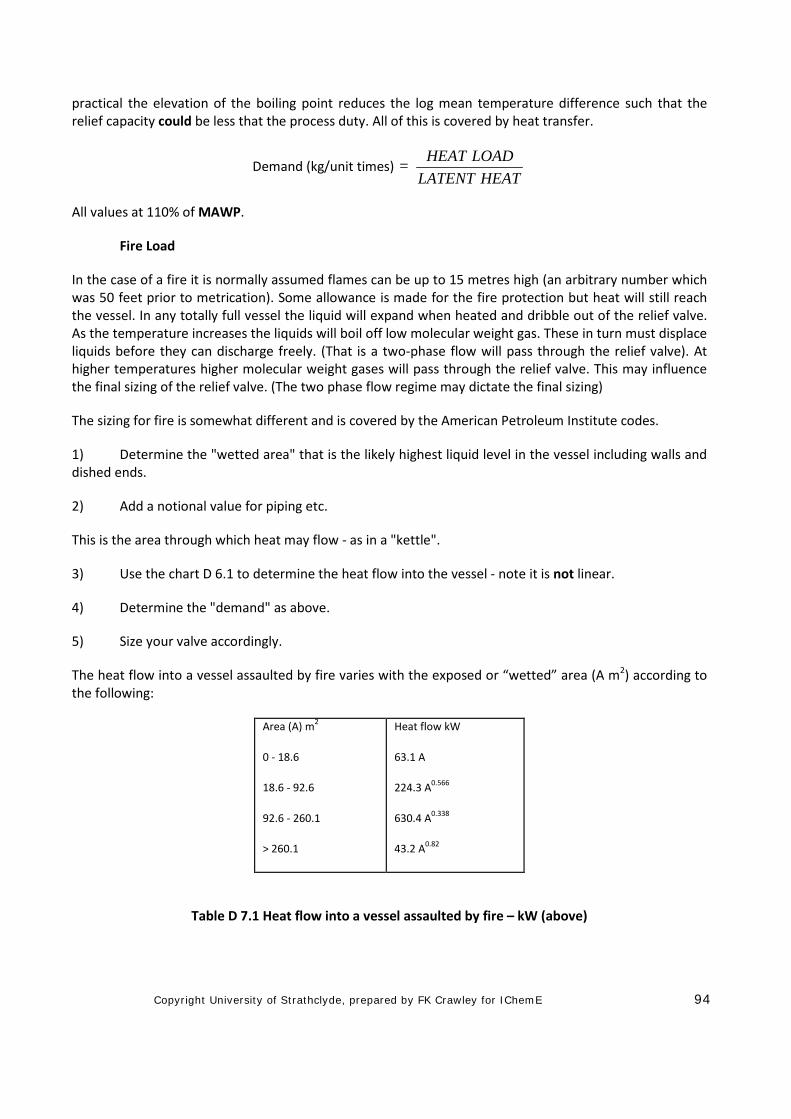
The heat flow into a vessel assaulted by fire varies with the exposed or “wetted” area (A m2) according to the following:
Area (A) m2
0 - 18.6
18.6 - 92.6
92.6 - 260.1
> 260.1
Heat flow kW
63.1 A
224.3 A0.566
630.4 A0.338
43.2 A0.82
Table D 7.1 Heat flow into a vessel assaulted by fire – kW (above)
Copyright University of Strathclyde, prepared by FK Crawley for IChemE 95
As will all designers the sizing valves is very much RULE DRIVEN and various extenuating factors are added such that the final assessment often looks like "a fix". One of the set of "fixes" are to be found for relief valves in fire, you can have factors for "LAGGING" and factors for "SURFACE DRAINAGE". Each is less than times 1. The lagging factor is usually 0.3 for securely held process lagging.
Disposal Routes Relief Headers and Flare Stacks (Thermal oxidisers)
The design of the relief headers should pay particular attention to drainage; lutes (U traps) are to be avoided, as are two-phase flow in the form of “slugs” and the mixing of water and cryogenic fluids which could cause the blockage of relief lines.
The designer should choose the disposal point for the fluid very carefully. If the vapours are to be burnt in a flare stack (also known as a “thermal oxidiser”) there should be a liquid knock out drum and a liquid disposal system before the gases enter the stack. There must also be adequate gas purging to avoid oxygen ingress as well as a reliable pilot system.
Flare stack areas are often remote from the plant to allow for high thermal radiation and liquid drop out. Process equipment should not be installed in areas of high thermal radiation.
Low level ground flares are becoming more common but the reliability of the pilot system must be exceedingly high. Where multistage burners are switched on by pressure switches their reliability must be adequate.
Low flow vents as well as high velocity vents for steam and inert gases can discharge directly to atmosphere if the gas dispersion is adequate and it is not pollutant. Toxic and corrosive vent gases, however, may have to be processed through a wash/scrubber system or even an incinerator to absorb, neutralise or destroy the harmful components of the gases.
Headers Sizing
The sizing of headers does not assume that "worst on worst" case or else they would be very heavy and very large. Normally fire relief is based on "Fire Zones or Areas"; this may be 20 to 30% of the plant area and treated as "moving circles" to capture the worst combination. Process relief may be sized for "works power failure" or "local power failure" whichever is the worse. A total power failure may result in a shut down with no heat flow into equipment but a local failure could produce a flooded condenser and produce a high demand.
• The header sizing must now consider:
• Pressure Drop
• Effects of back pressure on relief valves
• Drainage slope
• Single or two phase flow
• Sequence in header
(Low set pressure nearest the low pressure exit not the high pressure closed end).
Copyright University of Strathclyde, prepared by FK Crawley for IChemE 96
Flare stacks are a learned document all on its own right!
D 8 Hazardous Area Classification
Hazardous Area Classification follows on from the Dangerous Substances and Explosive Atmospheres Regs. It is quite a simple concept; it requires that the quality of electrical equipment is matched to the likelihood of there being flammable gases present, therefore it is risk based. In areas where flammable fluids are likely the quality of the electrical equipment must be such that sparks, for whatever reason, are unlikely indeed.
Hazardous Area Classification Methodologies, of which there are many, are based on the likely presence of flammable vapours. It does not consider the effects of an emergency such as a full bore rupture of piping. However fittings do leak and there could be a small plume of flammable gas round plant fittings.
The following is a very general presentation of the topic - each company or code will have its own approach which will probably be based on this model.
Sources of Fuel
There are three main sources of flammable gas:
• Continuously present where flammable gas is present such as inside vessels or sumps.
• Frequently present where flammable gas is
• Bund areas
expected during normal operation such as:
• Sample points
• Near pump seals
• Tanker loading points
• Atmospheric Storage Tank breathers
• Analyser houses
• Filters opened frequently for cleaning
• Vents and drains in frequent use
• Infrequently present where flammable gas is not
• Flanges
expected during normal operation:
• Blanked vents and drains
• Compressor seals (away from the immediate area)
Copyright University of Strathclyde, prepared by FK Crawley for IChemE 97
• Filters opened very infrequently
Classification of Zones
It is self evident that for safe design every effort should be made to reduce these sites by all engineering methods available.
It is normal to review the classification in a pragmatic way. If there are many flanges in an area the judgement may be that overall some leakage could be expected during normal operation. The durations have no scientific basis, other than they are based on “engineering judgement” and experience and that they work.
• Zone 0 flammable gas is expected over 1000 hrs/year
• Zone 1 flammable gas is expected 10 to 1000 hours/year (cross hatch in the figure above)
• Zone 2 flammable gas is expected up to 10 hours/year (single hatch in the figure above)
Non-Hazardous flammable gas is not expected by virtue of its location and the equipment in this area.
Note: non-hazardous does not mean safe – it only means that hazards are not
Extent of the Hazardous Zone
expected.
The extent of each zone depends upon the following factors:
• the type of hazard (possible outflow) • the effectiveness of ventilation • characteristics of the released flammable liquid, gas or vapour, particularly whether it is lighter or
heavier than air • the layout of equipment
For the extent of Zone, reference may be made to relevant codes, e.g.
Institute of Petroleum American Petroleum Institute British Standard, Corporate Codes,
HSE Guidelines - Quadvent
Code Distances
Each code will have slightly different distances for the extent of the three zones. It is not appropriate to quote them in detail but do not mix two codes, use one in its entirety.
It will be notes that the metrification of the imperial distances has produced a sense of accuracy due to the introduction of a decimal place!!! This is not a reality. The original distances were typically: 3 feet, 5 feet, 10 feet, 25 feet and 50 feet. These have become 1 m, 1.5 m, 3 m, 7.5 m and 15 m!
Copyright University of Strathclyde, prepared by FK Crawley for IChemE 98
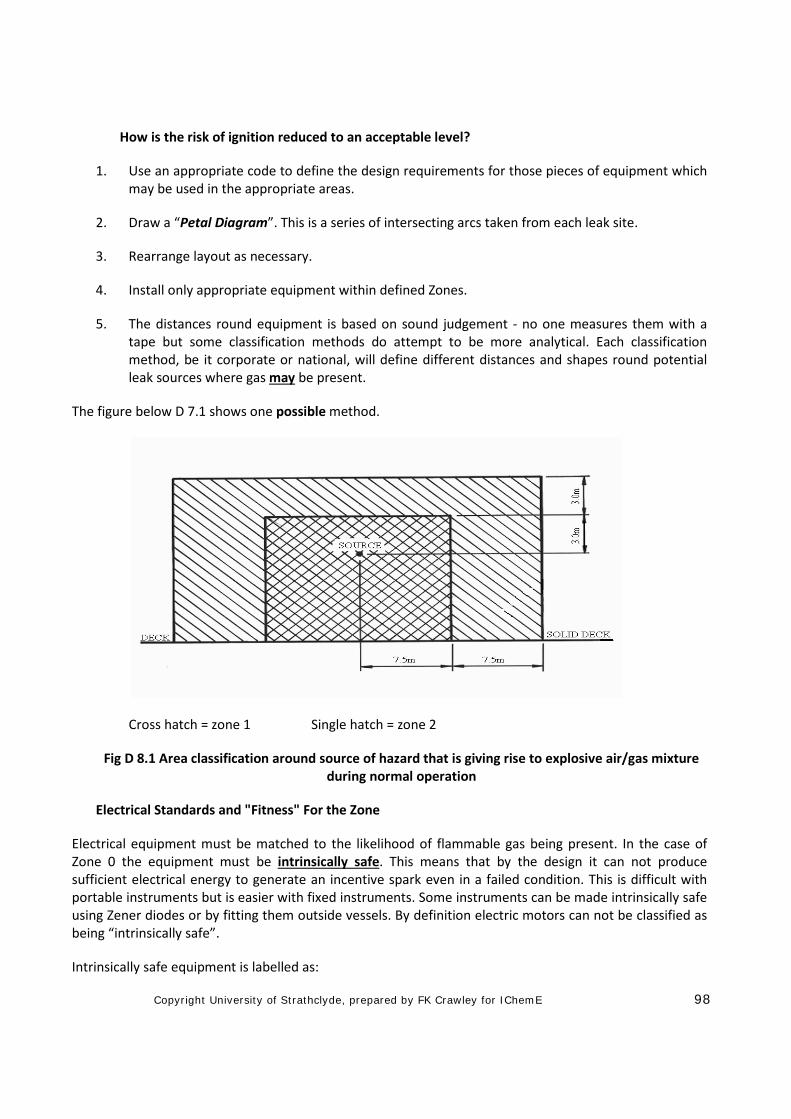
How is the risk of ignition reduced to an acceptable level?
1. Use an appropriate code to define the design requirements for those pieces of equipment which may be used in the appropriate areas.
2. Draw a “Petal Diagram”. This is a series of intersecting arcs taken from each leak site.
3. Rearrange layout as necessary.
4. Install only appropriate equipment within defined Zones.
5. The distances round equipment is based on sound judgement - no one measures them with a tape but some classification methods do attempt to be more analytical. Each classification method, be it corporate or national, will define different distances and shapes round potential leak sources where gas may be present.
The figure below D 7.1 shows one possible method.
Cross hatch = zone 1 Single hatch = zone 2
Fig D 8.1 Area classification around source of hazard that is giving rise to explosive air/gas mixture during normal operation
Electrical Standards and "Fitness" For the Zone
Electrical equipment must be matched to the likelihood of flammable gas being present. In the case of Zone 0 the equipment must be intrinsically safe. This means that by the design it can not produce sufficient electrical energy to generate an incentive spark even in a failed condition. This is difficult with portable instruments but is easier with fixed instruments. Some instruments can be made intrinsically safe using Zener diodes or by fitting them outside vessels. By definition electric motors can not be classified as being “intrinsically safe”.
Intrinsically safe equipment is labelled as:
Copyright University of Strathclyde, prepared by FK Crawley for IChemE 99
Exia or Exib
In Zone 1 areas there are two types of electric equipment preferred. In this case electrical equipment could be a motor or an instrument.
1. Pressurised and interlocked to shut down if pressuring fails, designated "Exp"
2. Flameproof - that is, the flanges are specially designed to quench any flame, designated "Exd".
Note: If anyone disturbs the interlock on Exp or interferes with the flanges on Exd equipment the electrical integrity may be lost.
"Exd" equipment is expensive and has to be inspected and checked for integrity on a regular basis so it is not surprising that electrical equipment is only localised in Zone 1 areas when it is really essential.
In Zone 1 areas sometimes equipment with increased safety features and special internal clearances are used and is designed "Exe". There is some debate about the use of Exe equipment in Zone 1. In Zone 2 areas the non sparking equipment used is designed "Exn". "None sparking" does not mean "never none sparking".
"Fitness" for the Gas (Energy)
Gases are categorised into groups according to the ignition energy. See Fires Part E.
• Group 1 contains the higher ignition energy gases.
• Group 11A contains saturated gases such as Methane, Ethane and the paraffin series.
• Group 11B includes unsaturated gases such as Ethylene or Propylene.
• Group 11C includes Hydrogen and Acetylene.
"Fitness" for Gas (Auto Ignition)
Gases are further categorised according to their auto Ignition Temperatures. See also Fires Part E.
T6 means the maximum surface temperature must not exceed 85oC under maximum load similarly
• T5 will not exceed 100oC
• T4 will not exceed 135oC
• T3 will not exceed 200oC
• T2 will not exceed 300oC
• T1 will not exceed 450oC
Overall “Fitness”
Electrical equipment must not only satisfy the demands of spark frequency but it must also match the demands of energy and temperature.
Copyright University of Strathclyde, prepared by FK Crawley for IChemE 100
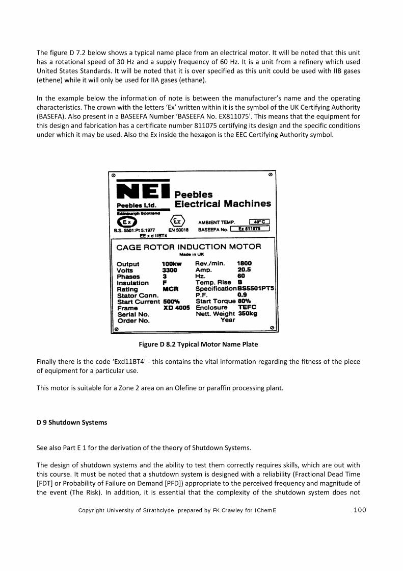
The figure D 7.2 below shows a typical name place from an electrical motor. It will be noted that this unit has a rotational speed of 30 Hz and a supply frequency of 60 Hz. It is a unit from a refinery which used United States Standards. It will be noted that it is over specified as this unit could be used with IIB gases (ethene) while it will only be used for IIA gases (ethane). In the example below the information of note is between the manufacturer’s name and the operating characteristics. The crown with the letters ‘Ex’ written within it is the symbol of the UK Certifying Authority (BASEFA). Also present in a BASEEFA Number ‘BASEEFA No. EX811075'. This means that the equipment for this design and fabrication has a certificate number 811075 certifying its design and the specific conditions under which it may be used. Also the Ex inside the hexagon is the EEC Certifying Authority symbol.
Figure D 8.2 Typical Motor Name Plate
Finally there is the code ‘Exd11BT4' - this contains the vital information regarding the fitness of the piece of equipment for a particular use.
This motor is suitable for a Zone 2 area on an Olefine or paraffin processing plant.
D 9 Shutdown Systems
See also Part E 1 for the derivation of the theory of Shutdown Systems.
The design of shutdown systems and the ability to test them correctly requires skills, which are out with this course. It must be noted that a shutdown system is designed with a reliability (Fractional Dead Time [FDT] or Probability of Failure on Demand [PFD]) appropriate to the perceived frequency and magnitude of the event (The Risk). In addition, it is essential that the complexity of the shutdown system does not
Copyright University of Strathclyde, prepared by FK Crawley for IChemE 101
inhibit safe and reliable operation. Shutdown systems sometimes have to be overridden to facilitate start up (such as a low level or low pressure shutdown – the shutdown system must be inhibited until a level or pressure is established. The design of the override is complex and must not be used indiscriminately.
The elements are:
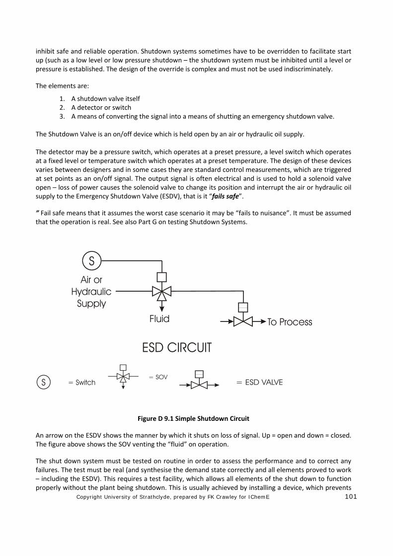
1. A shutdown valve itself 2. A detector or switch 3. A means of converting the signal into a means of shutting an emergency shutdown valve.
The Shutdown Valve is an on/off device which is held open by an air or hydraulic oil supply. The detector may be a pressure switch, which operates at a preset pressure, a level switch which operates at a fixed level or temperature switch which operates at a preset temperature. The design of these devices varies between designers and in some cases they are standard control measurements, which are triggered at set points as an on/off signal. The output signal is often electrical and is used to hold a solenoid valve open – loss of power causes the solenoid valve to change its position and interrupt the air or hydraulic oil supply to the Emergency Shutdown Valve (ESDV), that is it “fails safe”.
” Fail safe means that it assumes the worst case scenario it may be “fails to nuisance”. It must be assumed that the operation is real. See also Part G on testing Shutdown Systems.
Figure D 9.1 Simple Shutdown Circuit
An arrow on the ESDV shows the manner by which it shuts on loss of signal. Up = open and down = closed. The figure above shows the SOV venting the “fluid” on operation.
The shut down system must be tested on routine in order to assess the performance and to correct any failures. The test must be real (and synthesise the demand state correctly and all elements proved to work – including the ESDV). This requires a test facility, which allows all elements of the shut down to function properly without the plant being shutdown. This is usually achieved by installing a device, which prevents
Copyright University of Strathclyde, prepared by FK Crawley for IChemE 102
total closure of the ESDV (or plant shutdown). During testing, the shutdown system has to be inhibited leading to TRIP TEST DEAD TIME. The design of the test facilities and the test programme requires detailed analysis and obviously consideration has to be given to means of overriding the test facilities, should a genuine plant upset occur during the testing (TRIP TESTING). As already discussed, sometimes the shutdown has to be bypassed to facilitate start up of the process. This creates potential hazards if the bypass is left in place. The design can incorporate automatic resets of the shutdown or key controlled bypasses, controlled by rigorous procedures, which can only be operated by senior personnel. If the system is not restored to the operating state there results in a factor for HUMAN “UNRELIABILITY”.
In some shutdown systems it may not acceptable to override the trip for testing purposes. A fully redundant trip system is then installed as below, figures D 8.2 and D 8.3.
Each sensor and valve can be tested on routine with no interruptions to the process.
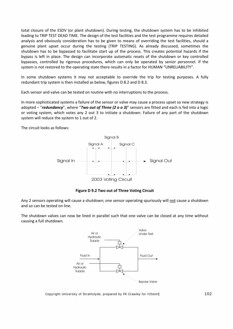
In more sophisticated systems a failure of the sensor or valve may cause a process upset so new strategy is adopted – “redundancy”, where “Two out of Three (2 o o 3)” sensors are fitted and each is fed into a logic or voting system, which votes any 2 out 3 to initiate a shutdown. Failure of any part of the shutdown system will reduce the system to 1 out of 2.
The circuit looks as follows:
Figure D 9.2 Two out of Three Voting Circuit
Any 2 sensors operating will cause a shutdown; one sensor operating spuriously will not cause a shutdown and so can be tested on line.
The shutdown valves can now be lined in parallel such that one valve can be closed at any time without causing a full shutdown.
Copyright University of Strathclyde, prepared by FK Crawley for IChemE 103
Figure D 9.3 Shut Down Valve with Test Valve in Parallel
Ultimately, 6 sensors could be used, 3 to close both valve A and 3 to close both valve B – this is a fully redundant showdown. The whole system can be fully tested without any Trip Test Dead Time. Nuclear shut downs are one level more complex and use multiple shut off valves in series. Even this can be devised to be tested on line.
THE DESIGN AND TESTING OF SHUTDOWN SYSTEMS IS AN ART/SKILL.
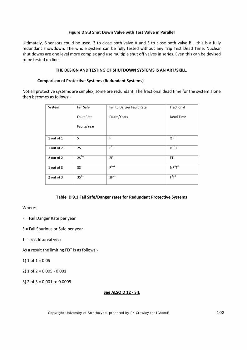
Comparison of Protective Systems (Redundant Systems)
Not all protective systems are simplex, some are redundant. The fractional dead time for the system alone then becomes as follows:-
System Fail Safe
Fault Rate
Faults/Year
Fail to Danger Fault Rate
Faults/Years
Fractional
Dead Time
1 out of 1 S F ½FT
1 out of 2 2S F2T ⅓F2T2
2 out of 2 2S2T 2F FT
1 out of 3 3S F3T2 ⅔F3T3
2 out of 3 3S2T 3F2T F2T2
Table D 9.1 Fail Safe/Danger rates for Redundant Protective Systems
Where: -
F = Fail Danger Rate per year
S = Fail Spurious or Safe per year
T = Test Interval year
As a result the limiting FDT is as follows:-
1) 1 of 1 = 0.05
2) 1 of 2 = 0.005 - 0.001
3) 2 of 3 = 0.001 to 0.0005
See ALSO D 12 - SIL
Copyright University of Strathclyde, prepared by FK Crawley for IChemE 104
However, the typical test dead time for a 2 out of 3 system can tend to zero as on-line testing is possible. The human element still remains.
D 10 Standards of isolation
Standards of Isolation are at the interface between safe design and safe operation.
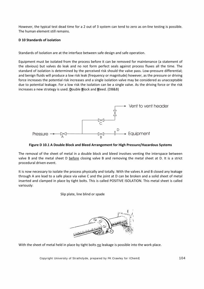
Equipment must be isolated from the process before it can be removed for maintenance (a statement of the obvious) but valves do leak and no not form perfect seals against process fluxes all the time. The standard of isolation is determined by the perceived risk should the valve pass. Low-pressure differential; and benign fluids will produce a low risk leak (frequency or magnitude) however, as the pressure or driving force increases the potential risk increases and a single isolation valve may be considered as unacceptable due to potential leakage. For a low risk the isolation can be a single valve. As the driving force or the risk increases a new strategy is used. Double Block and Bleed. (DB&B)
Figure D 10.1 A Double Block and Bleed Arrangement for High Pressure/Hazardous Systems
The removal of the sheet of metal in a double block and bleed involves venting the interspace between valve B and the metal sheet D before closing valve B and removing the metal sheet at D. It is a strict procedural driven event.
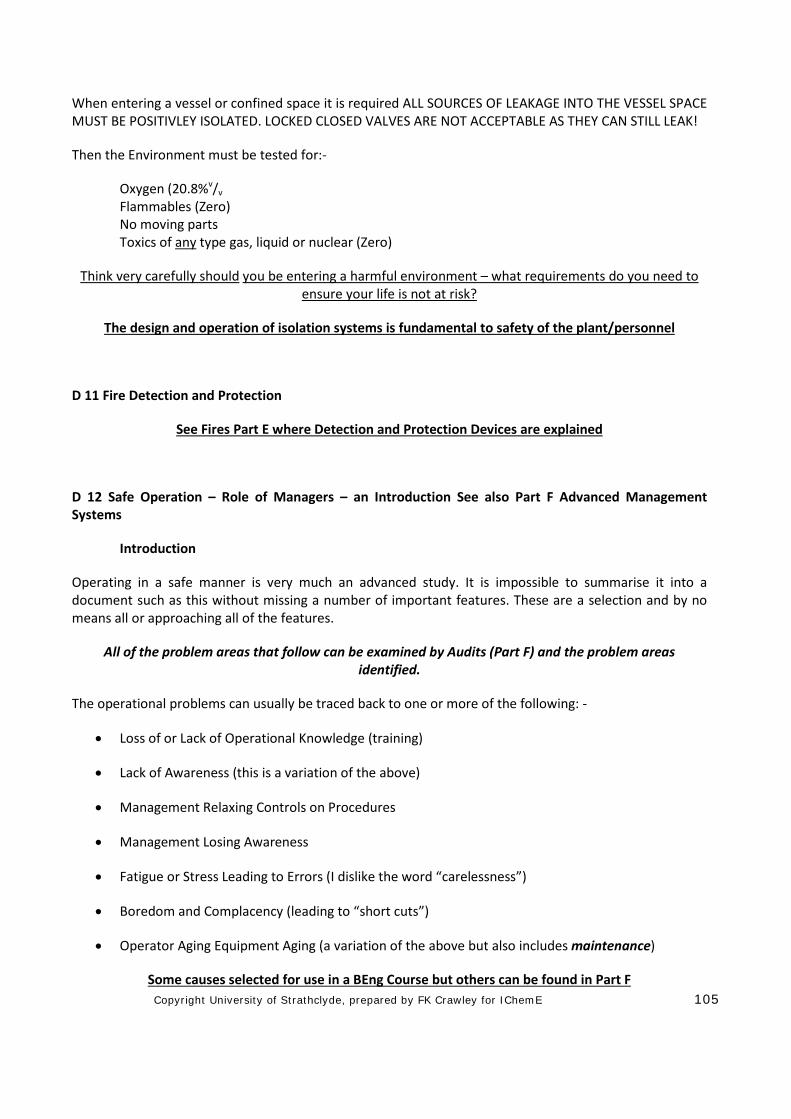
It is now necessary to isolate the process physically and totally. With the valves A and B closed any leakage through A are lead to a safe place via valve C and the joint at D can be broken and a solid sheet of metal inserted and clamped in place by tight bolts. This is called POSITIVE ISOLATION. This metal sheet is called variously:
Slip plate, line blind or spade
With the sheet of metal held in place by tight bolts no leakage is possible into the work place.
Copyright University of Strathclyde, prepared by FK Crawley for IChemE 105
When entering a vessel or confined space it is required ALL SOURCES OF LEAKAGE INTO THE VESSEL SPACE MUST BE POSITIVLEY ISOLATED. LOCKED CLOSED VALVES ARE NOT ACCEPTABLE AS THEY CAN STILL LEAK!
Then the Environment must be tested for:-
Oxygen (20.8%v/v Flammables (Zero) No moving parts Toxics of any type gas, liquid or nuclear (Zero)
Think very carefully should you be entering a harmful environment – what requirements do you need to ensure your life is not at risk?
The design and operation of isolation systems is fundamental to safety of the plant/personnel
D 11 Fire Detection and Protection
See Fires Part E where Detection and Protection Devices are explained
D 12 Safe Operation – Role of Managers – an Introduction See also Part F Advanced Management Systems
Introduction
Operating in a safe manner is very much an advanced study. It is impossible to summarise it into a document such as this without missing a number of important features. These are a selection and by no means all or approaching all of the features.
All of the problem areas that follow can be examined by Audits (Part F) and the problem areas identified.
The operational problems can usually be traced back to one or more of the following: -
• Loss of or Lack of Operational Knowledge (training)
• Lack of Awareness (this is a variation of the above)
• Management Relaxing Controls on Procedures
• Management Losing Awareness
• Fatigue or Stress Leading to Errors (I dislike the word “carelessness”)
• Boredom and Complacency (leading to “short cuts”)
• Operator Aging Equipment Aging (a variation of the above but also includes maintenance)
Some causes selected for use in a BEng Course but others can be found in Part F
Copyright University of Strathclyde, prepared by FK Crawley for IChemE 106
Operational Knowledge
The skills and knowledge of the Managers and the Operating Team are possibly the most important features in maintaining safe operation. The training of the manager may well have involved a degree of “grooming” such that the skills were available when the manager took up the role. However, it is impossible to learn all of the finer features of the plant and its peculiarities without experiencing them first.
One final potential for loss of skills and knowledge is during the final run down of a Plant prior to shut down and demolition when the best operations team is moved to a new plant and the ”second team” is left to carry on.
Hand over
One vital feature of the handover between Managers is the listing of the equipment, the problems experienced, the problems to look out for and how to handle them. This is the downward knowledge transfer. There is second source of knowledge to be found in databases of that type of process. Both are essential readings. Finally the operators can (and will) tell you some stories about their operating problems!
The shift or team hand over is equally important and should contain a list of the Permits in operation, the process status, any concerns or work that has to be carried out, such the preparation of a piece of equipment for maintenance.
Hand over in a Management Role and a Shift Role are one of the highest risk drivers
Training
The training of the Team Operators may well have been by the traditional cascade from the more senior operators. This does carry some potential risks in that some of the teaching may not be “best practice”, some may even be bad practice. Training Schools are available as are courses on operations. These should be reviewed and applied for new recruits. Refresher training is also to be encouraged.
The one situation where training is essential is on a new process or if the operation instructions have been changed. The instructions should be reviewed periodically, about once every two years to determine if they are appropriate to the plant in the light of best practice and new operational experience/conditions.
Training for Managers starts at University and then continues through CPD.
Awareness
Awareness comes from observation! It is necessary to “look” for potential problems. The only way of finding these problems, be they design and operations practice, is to look, listen and feel. (Look, listen and feel can also apply to an office environment. Tour the Plant (Office) each day, take a different route each day, try to approach the Plant (Office) from a different direction each day and try to time the tour at different times (if this is possible and it is recognised that this may be a constraint).
LOOK
Copyright University of Strathclyde, prepared by FK Crawley for IChemE 107
Look for trip hazards.
Observe operators (staff) – are they following the instructions?
Observe maintenance work – are they following the PtW? (Parts A and F)
Look for leaks, damaged lagging, loose fittings, “house keeping”, missing blanks on vents and drains. (Are there any trip hazards in an office?)
Where possible look around the process equipment – this may be limited in scope.
Look at the plant records and laboratory records. Are the parameters and analyses in the correct bands? (Are the design procedures used correctly in an office environment?)
If any parameter is out of range what actions have been or should have been taken?
If no action was taken what are your duties?
If you take your eyes out for a tour they will SEE something, somewhere!
LISTEN
Listen to what the operations team (staff) are saying – they may well have a good point but can not put it into technical language.
Listen to the grievances – they may be justified.
Listen to the worries – one of the team may have problems at home, health or financial problems.
Is there any evidence of persons being picked upon?
Is there any evidence of persons working outside their remit?
Listen to the equipment – it may be telling you something.
If you take your ears out for a tour they will HEAR something, somewhere
FEEL
Use your human feelings to identify concerns which may not be expressed explicitly.
Use your human touch with those with worries.
Feel the equipment – is it telling you anything?
If you take your senses out for a tour they will FEEL something, somewhere
Management Relaxing Control
This could be known as “aging management” when Management lose their enthusiasm (see later). This may be due to the age of the plant and equipment or it may be that the managers realise that the job is
Copyright University of Strathclyde, prepared by FK Crawley for IChemE 108
very much a “dead end” with no future. Senior Managers must be alert to this and to resist it by whatever means they can.
Audits are a very powerful tool in the event of managers relaxing controls.
Management Losing Awareness
This might be called “manager fatigue” The likely loss of awareness is that the Manager (or Operations Team) have been in the job for too long, have lost incentive and possibly see no future in that role. This is a Senior Management issue – does the problem go all of the way to the top, is the problem at the top of the organisation?
After a few years it is possible that some form of complacency will set in and it is time for that manager moved to a new post.
Audits are required on a routine to identify this “drift”.
Fatigue Leading to Errors (See also Part F)
Fatigue can come in two forms. First there is the “fatigue” caused by lack of stimulation or job advancement and second there is the pure physical and mental fatigue. The first is very much a Management issue and has to be dealt by Management; the second is the result of long, hard days on the Plant with little rest. This is most likely to be the result of a major shut down (turn-around) and a long and difficult start-up or an urgent design in the office. This is again a Management issue and all Managers must be alert to the symptoms and the effects on the team. At some time all staff will experience this form of fatigue and it beholds the prudent Manager to take a little longer to think through the problem and not to jump to the first conclusion!
There is no complete answer to this problem other that the use of a little management sensitivity!
Boredom and Complacency (leading to “short cuts”)
This can result from three main causes. The first is the Plant which has no vices, operates without any intervention and, possibly, is entering the end of life cycle. The second is likely to come from fatigue and the third comes from the lack of awareness by the Manager and the Manager relaxing control. The first cause is very much a Management issue but it is likely that it is a hidden effect that can best be addressed by audits. Inevitably “short cuts” will be adopted but the alert Manager will stop them at the first opportunity. The Manager must not tolerate these or else the Manager is equally guilty of “complacency”. If the Manager loses control it is time that he/she moved to a new post.
Audits (Part F) are powerful tools in identifying this problem.
Operator Aging
Just as with equipment operators age and become less alert and dextrous. This is a fact of life and as industries mature and go into their twilight years so also do the operators. The Managers must be alert to the aging process leads to a loss of dexterity but they must also be aware that the plant operations knowledge base is often held by the older/senior operators and that any retirements must not dilute this knowledge. This means that the average age of the team should be maintained and not allowed to drift upwards.
Copyright University of Strathclyde, prepared by FK Crawley for IChemE 109
Equipment Aging
This has two meanings, day to day maintenance and true end of life aging (as with a car or any mechanical equipment).
During the life of the plant equipment it will require routine maintenance due to “fair wear and tear”. There are three potential strategies for maintenance, one is “break-down maintenance”, the next is “routine maintenance” on a fixed schedule and the last is “on condition maintenance”. However, the act of maintaining equipment has the potential to age it! For example the removal of a bearing from a pump shaft does scrape a thin sliver of metal such that after many changes the fit is lost and the shaft can only be scrapped. (See end of life).
Maintenance
Routine Maintenance
This involves taking the equipment out of service (with a spare in place) and renewing key components which are known to known to have a finite life span before they come to the end of that span. This is very much the approach to maintenance on a car. Unfortunately not all of the components can be or are replaced and one will fail at some time in the future leading to break-down maintenance
Break-down Maintenance
This involves running the equipment until it fails in duty. Normally some of the more vulnerable equipment will be fitted with a stand-by spare so, provided the changeover can be affected before failure, all will be well.
Consider risk based maintenance for aging equipment. It may be more frequent than for new equipment. See also End of Life below
On Condition Maintenance
This involves monitoring “key performance parameters” on the equipment and when key indicators are found the maintenance is made.
The key parameters may be one or more of the following: -
• Vibration (velocity or acceleration) with or without analysis to assist the diagnostics
• Oil debris using Ferrography or Spectrometric Analysis of Oil Pollutants (SAOP)
• Heat
• True performance using process parameters such as heat transfer coefficients, polytrophic parameters and the like
• Physical inspection such as may be used for inspection of major pieces of equipment
• Non destructive techniques such as ultrasonic thickness detection are appropriate to both equipment and piping systems.

Copyright University of Strathclyde, prepared by FK Crawley for IChemE 110
There are no firm rights or wrongs for maintenance other than to note that any break-down which involves a loss of containment is not acceptable.
End of life
As the equipment reaches the end of life it has been overhauled on many occasions. Interference clearances or fits open up and the likelihood of failure can increase for that reason alone but also that the equipment is truly reaching the end of its life – the “wear out” phase”. In this phase there is no satisfactory maintenance routine other than total replacement. However it may be that the plant and equipment is now being “run into the ground” and the maintenance is reduced to a minimum when in fact it should be increased. This is a dangerous approach and carries many potential risks non less than the accumulative wear and tear which may result in the following problems: -
• Corrosion Under Insulation – external - (CUI)
• Corrosion inside piping
• Erosion inside piping
• Fatigue in equipment subject to cyclic loads (pressurising and depressurising is one such cyclic load)
As equipment ages a new approach is required – RISK BASED MAINTENANCE. This requires that the frequency of maintenance is adjusted to the perceived risk. It may be that the frequency must be increased or that special attention is paid to corrosion. In high temperature equipment it might be necessary to monitor the equipment for “high temperature creep” and in equipment subject to cyclic loads it might be necessary to monitor for “fatigue”.
These examples are only some of many monitoring policies.
At some point the equipment will be so aged that no matter what amount of maintenance it will have to be scrapped.
There is always a great temptation to “Sweat the Assets” at the end of life. This must be resisted, as it has been a major cause of incidents.
D 13 Layer of Protection Analysis (LOPA) and Safety Integrity Level (SIL)
One of the inevitable changes in any a dynamic technology is that old techniques are reinvented and called by new names!! In addition it develops its own jargon or language; this makes it a form of closed shop! This is true of LOPA and SIL. Both have been in use for over 40 years but were known by another name. LOPA developed from the very first form of Risk Assessment when the conditional probabilities were ill defined and SIL was developed from a relatively simple technique which was an attempt to classify the performance of shutdown systems against loss of production, environment and life.
LOPA should be treated as “screening tool” as it is more tuned to low risk event and not to high risk events (see the definitions).
These are tools of which all engineers should be aware.
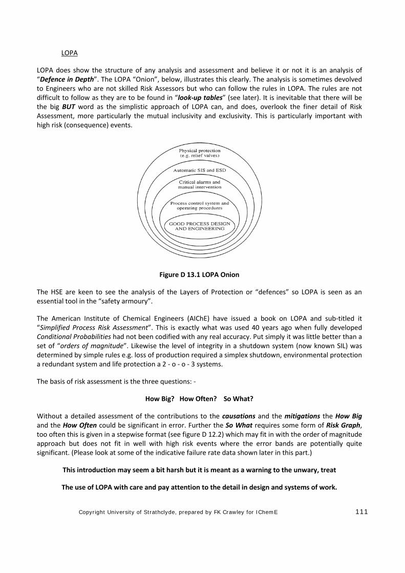
Copyright University of Strathclyde, prepared by FK Crawley for IChemE 111
LOPA
LOPA does show the structure of any analysis and assessment and believe it or not it is an analysis of “Defence in Depth”. The LOPA “Onion”, below, illustrates this clearly. The analysis is sometimes devolved to Engineers who are not skilled Risk Assessors but who can follow the rules in LOPA. The rules are not difficult to follow as they are to be found in “look-up tables” (see later). It is inevitable that there will be the big BUT word as the simplistic approach of LOPA can, and does, overlook the finer detail of Risk Assessment, more particularly the mutual inclusivity and exclusivity. This is particularly important with high risk (consequence) events.
Figure D 13.1 LOPA Onion
The HSE are keen to see the analysis of the Layers of Protection or “defences” so LOPA is seen as an essential tool in the “safety armoury”.
The American Institute of Chemical Engineers (AIChE) have issued a book on LOPA and sub-titled it “Simplified Process Risk Assessment”. This is exactly what was used 40 years ago when fully developed Conditional Probabilities had not been codified with any real accuracy. Put simply it was little better than a set of “orders of magnitude”. Likewise the level of integrity in a shutdown system (now known SIL) was determined by simple rules e.g. loss of production required a simplex shutdown, environmental protection a redundant system and life protection a 2 - o - o - 3 systems.
The basis of risk assessment is the three questions: -
How Big? How Often? So What?
Without a detailed assessment of the contributions to the causations and the mitigations the How Big and the How Often could be significant in error. Further the So What requires some form of Risk Graph, too often this is given in a stepwise format (see figure D 12.2) which may fit in with the order of magnitude approach but does not fit in well with high risk events where the error bands are potentially quite significant. (Please look at some of the indicative failure rate data shown later in this part.)
This introduction may seem a bit harsh but it is meant as a warning to the unwary, treat
The use of LOPA with care and pay attention to the detail in design and systems of work.
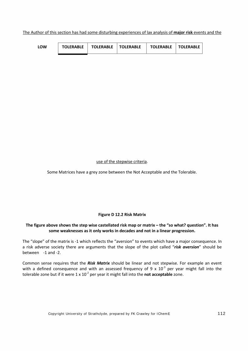
Copyright University of Strathclyde, prepared by FK Crawley for IChemE 112
The Author of this section has had some disturbing experiences of lax analysis of major risk events and the
use of the stepwise criteria.
Some Matrices have a grey zone between the Not Acceptable and the Tolerable.
Figure D 12.2 Risk Matrix
The figure above shows the step wise castellated risk map or matrix – the “so what? question”. It has some weaknesses as it only works in decades and not in a linear progression.
The “slope” of the matrix is -1 which reflects the “aversion” to events which have a major consequence. In a risk adverse society there are arguments that the slope of the plot called “risk aversion” should be between -1 and -2.
Common sense requires that the Risk Matrix should be linear and not stepwise. For example an event with a defined consequence and with an assessed frequency of 9 x 10⁻³ per year might fall into the tolerable zone but if it were 1 x 10⁻² per year it might fall into the not acceptable zone.
LOW TOLERABLE TOLERABLE TOLERABLE TOLERABLE TOLERABLE
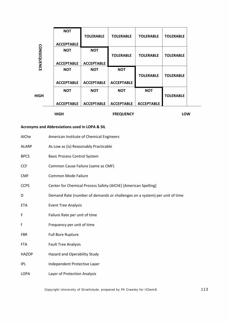
Copyright University of Strathclyde, prepared by FK Crawley for IChemE 113
Acronyms and Abbreviations used in LOPA & SIL
AIChe American Institute of Chemical Engineers
ALARP As Low as (is) Reasonably Practicable
BPCS Basic Process Control System
CCF Common Cause Failure (same as CMF)
CMF Common Mode Failure
CCPS Center for Chemical Process Safety (AIChE) [American Spelling]
D Demand Rate (number of demands or challenges on a system) per unit of time
ETA Event Tree Analysis
F Failure Rate per unit of time
f Frequency per unit of time
FBR Full Bore Rupture
FTA Fault Tree Analysis
HAZOP Hazard and Operability Study
IPL Independent Protective Layer
LOPA Layer of Protection Analysis
CON
SEQU
ENCE
NOT
ACCEPTABLE
TOLERABLE TOLERABLE TOLERABLE TOLERABLE
NOT
ACCEPTABLE
NOT
ACCEPTABLE
TOLERABLE TOLERABLE TOLERABLE
NOT
ACCEPTABLE
NOT
ACCEPTABLE
NOT
ACCEPTABLE
TOLERABLE TOLERABLE
HIGH NOT
ACCEPTABLE
NOT
ACCEPTABLE
NOT
ACCEPTABLE
NOT
ACCEPTABLE
TOLERABLE
HIGH FREQUENCY LOW
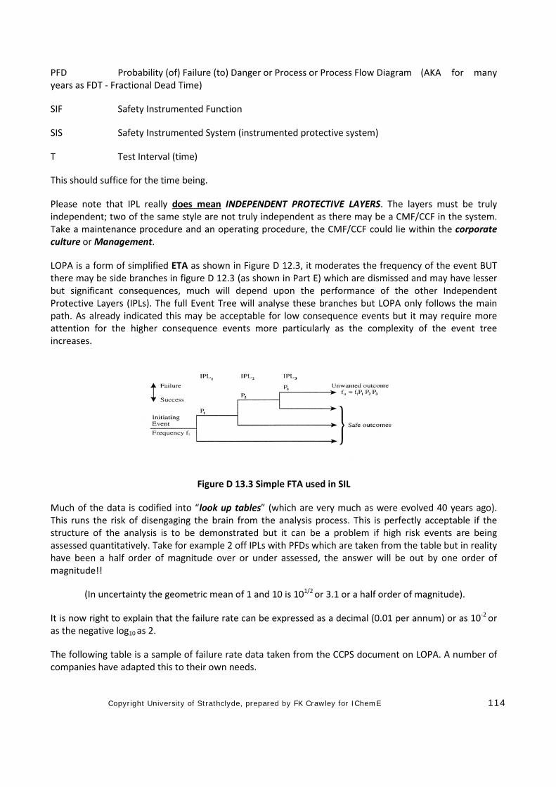
Copyright University of Strathclyde, prepared by FK Crawley for IChemE 114
PFD Probability (of) Failure (to) Danger or Process or Process Flow Diagram (AKA for many years as FDT - Fractional Dead Time)
SIF Safety Instrumented Function
SIS Safety Instrumented System (instrumented protective system)
T Test Interval (time)
This should suffice for the time being.
Please note that IPL really does mean INDEPENDENT PROTECTIVE LAYERS. The layers must be truly independent; two of the same style are not truly independent as there may be a CMF/CCF in the system. Take a maintenance procedure and an operating procedure, the CMF/CCF could lie within the corporate culture or Management.
LOPA is a form of simplified ETA as shown in Figure D 12.3, it moderates the frequency of the event BUT there may be side branches in figure D 12.3 (as shown in Part E) which are dismissed and may have lesser but significant consequences, much will depend upon the performance of the other Independent Protective Layers (IPLs). The full Event Tree will analyse these branches but LOPA only follows the main path. As already indicated this may be acceptable for low consequence events but it may require more attention for the higher consequence events more particularly as the complexity of the event tree increases.
Figure D 13.3 Simple FTA used in SIL
Much of the data is codified into “look up tables” (which are very much as were evolved 40 years ago). This runs the risk of disengaging the brain from the analysis process. This is perfectly acceptable if the structure of the analysis is to be demonstrated but it can be a problem if high risk events are being assessed quantitatively. Take for example 2 off IPLs with PFDs which are taken from the table but in reality have been a half order of magnitude over or under assessed, the answer will be out by one order of magnitude!!
(In uncertainty the geometric mean of 1 and 10 is 101/2 or 3.1 or a half order of magnitude).
It is now right to explain that the failure rate can be expressed as a decimal (0.01 per annum) or as 10-2 or as the negative log10 as 2.
The following table is a sample of failure rate data taken from the CCPS document on LOPA. A number of companies have adapted this to their own needs.
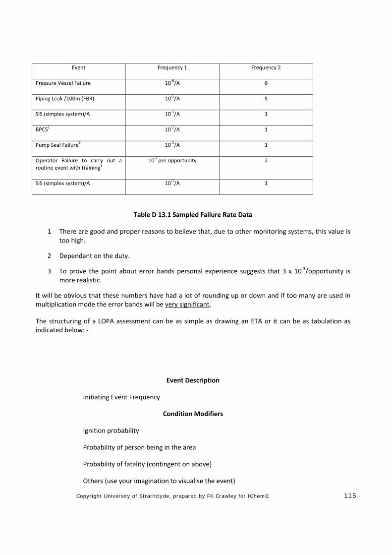
Copyright University of Strathclyde, prepared by FK Crawley for IChemE 115
Event Frequency 1 Frequency 2
Pressure Vessel Failure 10-6/A 6
Piping Leak /100m (FBR) 10-5/A 5
SIS (simplex system)/A 10-1/A 1
BPCS1 10-1/A 1
Pump Seal Failure2 10-1/A 1
Operator Failure to carry out a routine event with training3
10-2 per opportunity 2
SIS (simplex system)/A 10-1/A 1
Table D 13.1 Sampled Failure Rate Data
1 There are good and proper reasons to believe that, due to other monitoring systems, this value is too high.
2 Dependant on the duty.
3 To prove the point about error bands personal experience suggests that 3 x 10⁻³/opportunity is more realistic.
It will be obvious that these numbers have had a lot of rounding up or down and if too many are used in multiplication mode the error bands will be very significant.
The structuring of a LOPA assessment can be as simple as drawing an ETA or it can be as tabulation as indicated below: -
Event Description
Initiating Event Frequency
Condition Modifiers
Ignition probability
Probability of person being in the area
Probability of fatality (contingent on above)
Others (use your imagination to visualise the event)
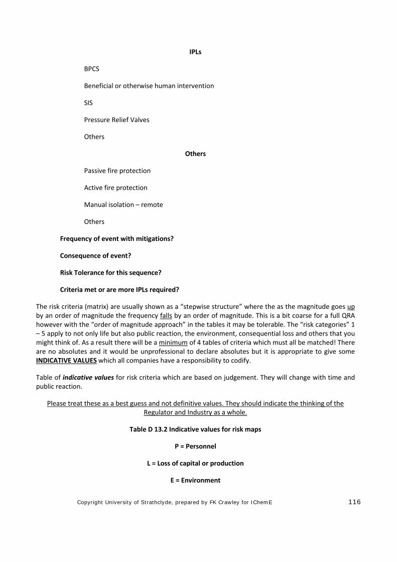
Copyright University of Strathclyde, prepared by FK Crawley for IChemE 116
IPLs
BPCS
Beneficial or otherwise human intervention
SIS
Pressure Relief Valves
Others
Others
Passive fire protection
Active fire protection
Manual isolation – remote
Others
Frequency of event with mitigations?
Consequence of event?
Risk Tolerance for this sequence?
Criteria met or are more IPLs required?
The risk criteria (matrix) are usually shown as a “stepwise structure” where the as the magnitude goes up by an order of magnitude the frequency falls by an order of magnitude. This is a bit coarse for a full QRA however with the “order of magnitude approach” in the tables it may be tolerable. The “risk categories” 1 – 5 apply to not only life but also public reaction, the environment, consequential loss and others that you might think of. As a result there will be a minimum of 4 tables of criteria which must all be matched! There are no absolutes and it would be unprofessional to declare absolutes but it is appropriate to give some INDICATIVE VALUES which all companies have a responsibility to codify.
Table of indicative values for risk criteria which are based on judgement. They will change with time and public reaction.
Please treat these as a best guess and not definitive values. They should indicate the thinking of the Regulator and Industry as a whole.
Table D 13.2 Indicative values for risk maps
P = Personnel
L = Loss of capital or production
E = Environment
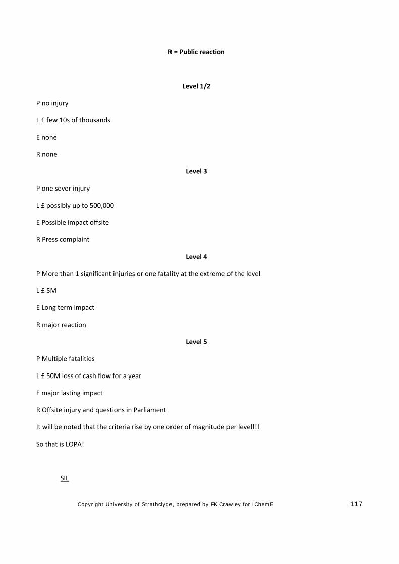
Copyright University of Strathclyde, prepared by FK Crawley for IChemE 117
R = Public reaction
Level 1/2
P no injury
L £ few 10s of thousands
E none
R none
Level 3
P one sever injury
L £ possibly up to 500,000
E Possible impact offsite
R Press complaint
Level 4
P More than 1 significant injuries or one fatality at the extreme of the level
L £ 5M
E Long term impact
R major reaction
Level 5
P Multiple fatalities
L £ 50M loss of cash flow for a year
E major lasting impact
R Offsite injury and questions in Parliament
It will be noted that the criteria rise by one order of magnitude per level!!!
So that is LOPA!
SIL
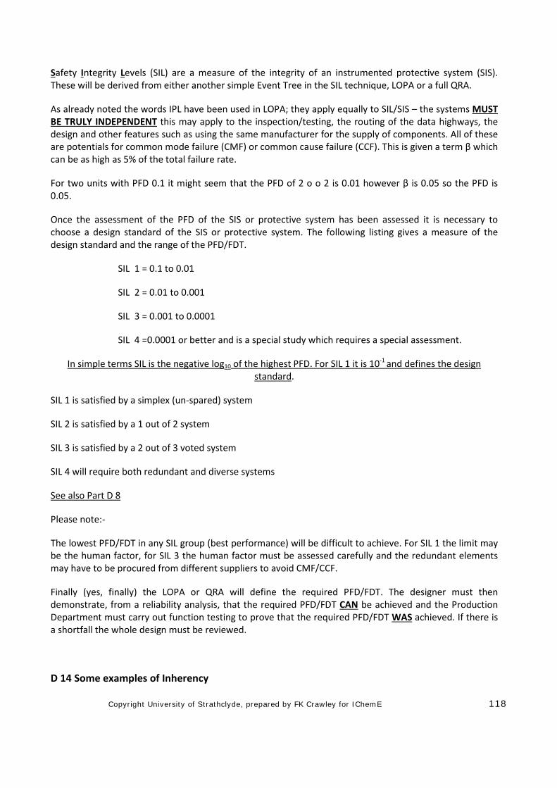
Copyright University of Strathclyde, prepared by FK Crawley for IChemE 118
Safety Integrity Levels (SIL) are a measure of the integrity of an instrumented protective system (SIS). These will be derived from either another simple Event Tree in the SIL technique, LOPA or a full QRA.
As already noted the words IPL have been used in LOPA; they apply equally to SIL/SIS – the systems MUST BE TRULY INDEPENDENT this may apply to the inspection/testing, the routing of the data highways, the design and other features such as using the same manufacturer for the supply of components. All of these are potentials for common mode failure (CMF) or common cause failure (CCF). This is given a term β which can be as high as 5% of the total failure rate.
For two units with PFD 0.1 it might seem that the PFD of 2 o o 2 is 0.01 however β is 0.05 so the PFD is 0.05.
Once the assessment of the PFD of the SIS or protective system has been assessed it is necessary to choose a design standard of the SIS or protective system. The following listing gives a measure of the design standard and the range of the PFD/FDT.
SIL 1 = 0.1 to 0.01
SIL 2 = 0.01 to 0.001
SIL 3 = 0.001 to 0.0001
SIL 4 =0.0001 or better and is a special study which requires a special assessment.
In simple terms SIL is the negative log10 of the highest PFD. For SIL 1 it is 10-1 and defines the design standard.
SIL 1 is satisfied by a simplex (un-spared) system
SIL 2 is satisfied by a 1 out of 2 system
SIL 3 is satisfied by a 2 out of 3 voted system
SIL 4 will require both redundant and diverse systems
See also Part D 8
Please note:-
The lowest PFD/FDT in any SIL group (best performance) will be difficult to achieve. For SIL 1 the limit may be the human factor, for SIL 3 the human factor must be assessed carefully and the redundant elements may have to be procured from different suppliers to avoid CMF/CCF.
Finally (yes, finally) the LOPA or QRA will define the required PFD/FDT. The designer must then demonstrate, from a reliability analysis, that the required PFD/FDT CAN be achieved and the Production Department must carry out function testing to prove that the required PFD/FDT WAS achieved. If there is a shortfall the whole design must be reviewed.
D 14 Some examples of Inherency
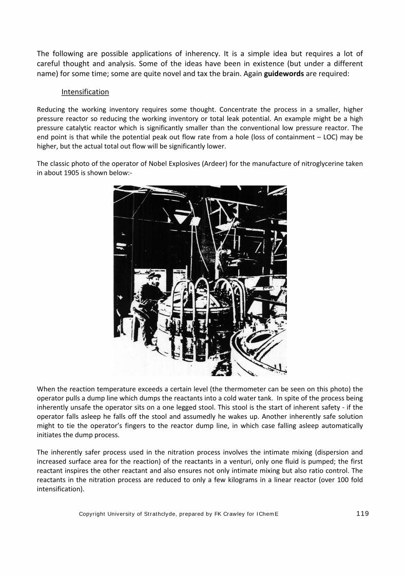
Copyright University of Strathclyde, prepared by FK Crawley for IChemE 119
The following are possible applications of inherency. It is a simple idea but requires a lot of careful thought and analysis. Some of the ideas have been in existence (but under a different name) for some time; some are quite novel and tax the brain. Again guidewords are required:
Intensification
Reducing the working inventory requires some thought. Concentrate the process in a smaller, higher pressure reactor so reducing the working inventory or total leak potential. An example might be a high pressure catalytic reactor which is significantly smaller than the conventional low pressure reactor. The end point is that while the potential peak out flow rate from a hole (loss of containment – LOC) may be higher, but the actual total out flow will be significantly lower.
The classic photo of the operator of Nobel Explosives (Ardeer) for the manufacture of nitroglycerine taken in about 1905 is shown below:-
When the reaction temperature exceeds a certain level (the thermometer can be seen on this photo) the operator pulls a dump line which dumps the reactants into a cold water tank. In spite of the process being inherently unsafe the operator sits on a one legged stool. This stool is the start of inherent safety - if the operator falls asleep he falls off the stool and assumedly he wakes up. Another inherently safe solution might to tie the operator’s fingers to the reactor dump line, in which case falling asleep automatically initiates the dump process.
The inherently safer process used in the nitration process involves the intimate mixing (dispersion and increased surface area for the reaction) of the reactants in a venturi, only one fluid is pumped; the first reactant inspires the other reactant and also ensures not only intimate mixing but also ratio control. The reactants in the nitration process are reduced to only a few kilograms in a linear reactor (over 100 fold intensification).
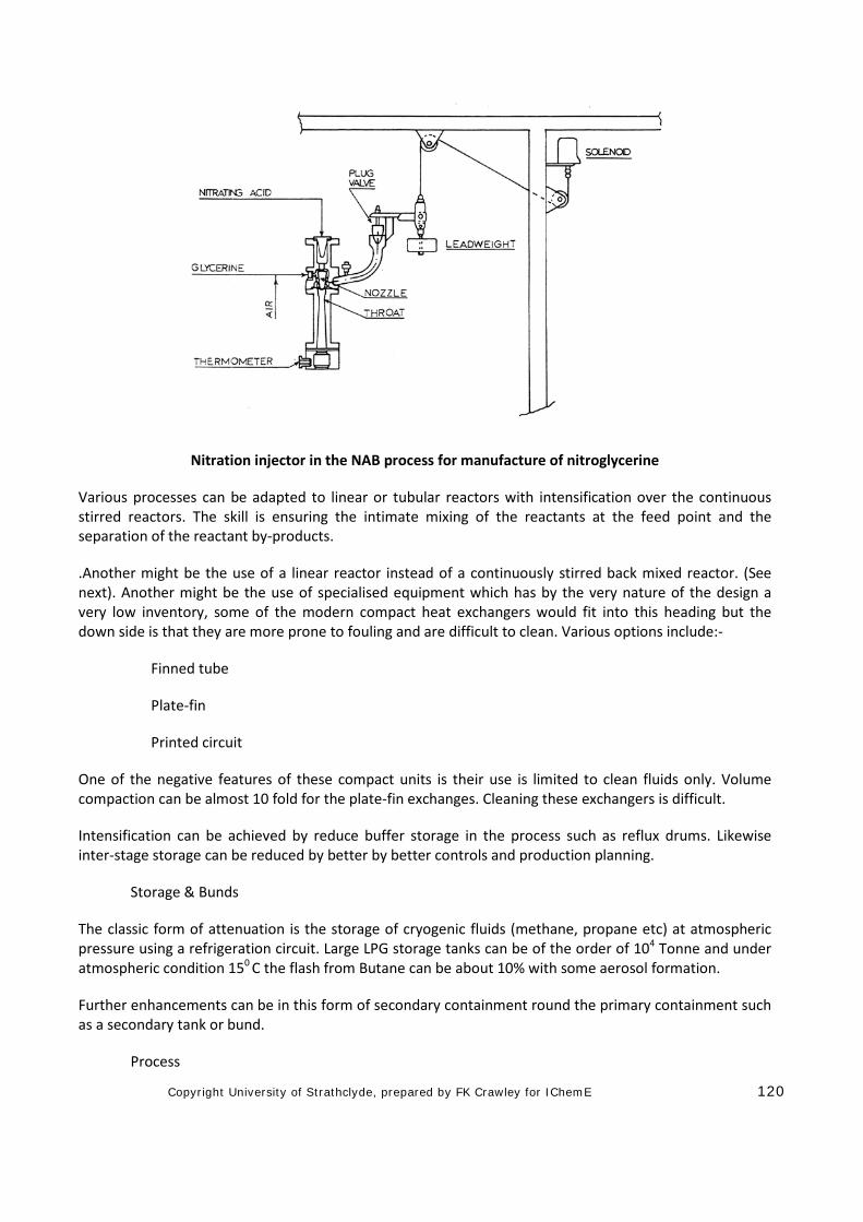
Copyright University of Strathclyde, prepared by FK Crawley for IChemE 120
Nitration injector in the NAB process for manufacture of nitroglycerine
Various processes can be adapted to linear or tubular reactors with intensification over the continuous stirred reactors. The skill is ensuring the intimate mixing of the reactants at the feed point and the separation of the reactant by-products.
.Another might be the use of a linear reactor instead of a continuously stirred back mixed reactor. (See next). Another might be the use of specialised equipment which has by the very nature of the design a very low inventory, some of the modern compact heat exchangers would fit into this heading but the down side is that they are more prone to fouling and are difficult to clean. Various options include:-
Finned tube
Plate-fin
Printed circuit
One of the negative features of these compact units is their use is limited to clean fluids only. Volume compaction can be almost 10 fold for the plate-fin exchanges. Cleaning these exchangers is difficult.
Intensification can be achieved by reduce buffer storage in the process such as reflux drums. Likewise inter-stage storage can be reduced by better by better controls and production planning.
Storage & Bunds
The classic form of attenuation is the storage of cryogenic fluids (methane, propane etc) at atmospheric pressure using a refrigeration circuit. Large LPG storage tanks can be of the order of 104 Tonne and under atmospheric condition 150 C the flash from Butane can be about 10% with some aerosol formation.
Further enhancements can be in this form of secondary containment round the primary containment such as a secondary tank or bund.
Process
Copyright University of Strathclyde, prepared by FK Crawley for IChemE 121
Any process which uses a catalyst will be expected to operate at lower temperatures and/or pressures.
In general, for the same conditions of temperatures and pressure a liquid leak from any given hole size will be 10 to 15 times that of a gas leak. The value is dependent on the fluid properties and is not a fixed value and may be influenced by any flashing effects at the orifice - a flashing leak is about a quarter of the liquid leak. This suggests that catalysed gas phase reactions are better than liquid phase reactions but is contrary to the laws of mass action.
The original polythene plants operated at a pressure of about 109 Pa but the modern ones operate at nearer 106 Pa with enhanced catalysts. Changes in the polypropylene process have resulted in a vapour phase reaction as opposed to liquid phase reactions. This example straddles “intensification” and “attenuation”.
The variable of Temperature, Pressure and Phase do make separation processes less amenable to alteration but reactors and storage do offer some scope.
Tray hold up can be reduced by a factor of two for packed columns and a factor of four for film type trays. One distillation column for the separation of propane and propylene was 5m diameter and contained 150 trays. The reflux ratio was 11:1 and the velocity time lag between a change in reflux and its effect on the base was of the order of 10 minutes. The column was very sluggish!
The inventories were:-
Trays & downcomers 40m3
Reflux Drum 50m3
Base 50m3
140m3 or 100 Tonnes
The feed rate was 30 tonnes per hour therefore the holdup represented 3 hours of production!! Various inherently safer routes could be considered:
Operating at lower pressure with enhanced relative volatility/separation
Change the column intervals with savings in the tray hold up and the reflux drum and base inventory.
(The condenser for this column used ‘re-used’ water - it first passed through refrigeration condensers so saving power on the compressor drivers before its second use in a condenser. Efficiency and environmental issues were not always in harmony with safety!) See also ‘HIGEE’.
HIGEE is a concept looking for an application. It appears to be technically sound but has a number of engineering weaknesses namely the seal of the drive shaft and its overall availability. The process is essentially a rotating mesh or packed drum with a liquid fed at the centre and a vapour exit at the periphery.
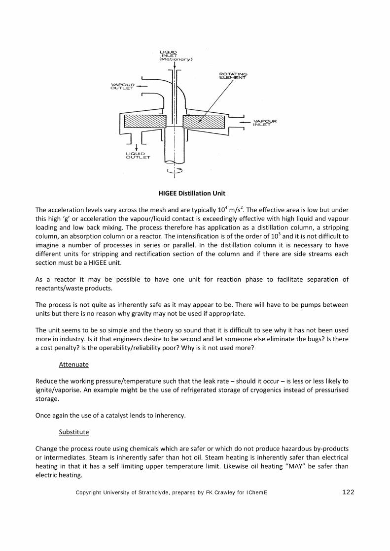
Copyright University of Strathclyde, prepared by FK Crawley for IChemE 122
HIGEE Distillation Unit
The acceleration levels vary across the mesh and are typically 104 m/s2. The effective area is low but under this high ‘g’ or acceleration the vapour/liquid contact is exceedingly effective with high liquid and vapour loading and low back mixing. The process therefore has application as a distillation column, a stripping column, an absorption column or a reactor. The intensification is of the order of 103 and it is not difficult to imagine a number of processes in series or parallel. In the distillation column it is necessary to have different units for stripping and rectification section of the column and if there are side streams each section must be a HIGEE unit.
As a reactor it may be possible to have one unit for reaction phase to facilitate separation of reactants/waste products.
The process is not quite as inherently safe as it may appear to be. There will have to be pumps between units but there is no reason why gravity may not be used if appropriate.
The unit seems to be so simple and the theory so sound that it is difficult to see why it has not been used more in industry. Is it that engineers desire to be second and let someone else eliminate the bugs? Is there a cost penalty? Is the operability/reliability poor? Why is it not used more?
Attenuate
Reduce the working pressure/temperature such that the leak rate – should it occur – is less or less likely to ignite/vaporise. An example might be the use of refrigerated storage of cryogenics instead of pressurised storage.
Once again the use of a catalyst lends to inherency.
Substitute
Change the process route using chemicals which are safer or which do not produce hazardous by-products or intermediates. Steam is inherently safer than hot oil. Steam heating is inherently safer than electrical heating in that it has a self limiting upper temperature limit. Likewise oil heating “MAY” be safer than electric heating.
Copyright University of Strathclyde, prepared by FK Crawley for IChemE 123
Change
While the concept of change is simple it does require a bit of thought! Consider the “change” in a layout such as to segregate flammable materials from sources of ignition or the positioning of a valve such that access is enhanced – the layout or access is then inherently safer. Change may involve a new process if the environmental implications were adverse. “Change” is simple but finding the solution is less so!
Eliminate
This is more a statement of the obvious. Consider the design pressures; can you eliminate the need for overpressure protection by the selection of the equipment design pressures?
Has the need for a protective system been fully analysed and understood. Is there a more simple solution?
Eliminate and Change look at the same basics problem from different directions.
It is possible to specify pumps which do not have seals. In effect the leak source at the seal is eliminated.
A welded system as opposed to flanged systems eliminates a leak source BUT it might make maintenance more difficult.
Simplify
This is self evident.
Is there an easier way? There is no doubt that Engineers are taught to think verticality. ‘This the way we always do it’. Engineers do not always look for other ways. The design is usually examined, a hazard identified and then a protective system added. Why not find an alternative route? The simple ‘break tank’ in a home or elsewhere is a means to preventing reverse flow and cross contamination, it is inherently safer than a non return valve.
Capture and recover
This idea may apply more to the environment. An alternative may be “recycle”.
Modern flare systems can capture leakage into the piping from passing (leaking) valves, compress and recycle it to the process as opposed to combustion.
Getting it Right First Time
Avoid the need for last minute change or even recognising the whole spectrum of conditions which may apply so choosing the correct materials for fabrication and the choice of design pressure for equipment. It can also mean “de-clutter” the process and avoid a surfeit of “add-on safety features” which do little for SHE or efficiency but create operational problems.
Can a process be devised which does not require a complex pressure relief system by the specification of the system design pressures? In one hydrocarbon processing plant, the operating pressure was 900kPa and a relief system was required because the vessels were designed for 1100kPa (the piping was designed for 1800kPa). It was then realised that the relief valves discharged to atmosphere and vapours could fall to the ground, ignite and generate a VCE. The initial solution was to add a simple high pressure shut down system. The performance was assessed and it was found that the discharge frequency was still too high, so
Copyright University of Strathclyde, prepared by FK Crawley for IChemE 124
a 2 out of 3 shut down system was added (vertical thought). The maximum process pressure due to heating with steam was 1500kPa - the piping was adequate for this and a small increase in the wall thickness - possible as with as little as 1mm of steel would have eliminated all the soul searching. Of course a small fire relief system would still be required, this would be relatively cheap, but the inherent safety and operability would be much higher. The net cost of thicker vessels would have been lower than the ‘added on’ features and the process would be more operable.
What is the worst case scenario and can a change to the design eliminate the scenario?
The classic example of this dilemma is to be found with Chernobyl Pressurised Water Reactor. The RBMK - 1000 reactor had a positive void coefficient which meant that at below 20% power, there was a positive power coefficient which made it intrinsically unstable at low power. The accident occurred basically because the reactor entered this regime for a series of reasons explained in Part H. The RBMK - 1000 did not fail safe but the UK PWRs do fail safe, the difference between the two reactors is based on efficiency - the stable unit is less efficient but it is safer.
Second Chance/fails safe
The ability to recover from and to survive an upset or to tolerate the extremes of the operating/upset conditions envelope. The brittle failure of a heat exchanger at Longford, Victoria, Australia was caused by a thermal shock. If the materials were specified for colder duty the exchanger would have tolerated the shock.
Variations on fail safe can be found on the control of the rates of reactants and the thermal inertia in the system. The cyclohexane oxidation process has such inertia but entails a high recycle of reactants.
The hydrogenation of ethyne in Olefine plants can either be at the front end where the process gases, a mix of hydrocarbons and hydrogen, are fed across a catalyst. The alternative process at the back end, involves feeding hydrogen into a mixed ethane, ethene, ethyne. In the front end process, the reactor has a high thermal inertia and the arrest of the feed produces no runaway. The back end process requires careful ratio control of the fed and hydrogen, hydrogen has to be stopped to avoid thermal runaway and explosive decomposition of ethene. The first catalyst is truly fail safe. Once again the problem illustrating fail safe is finding specific and easy to explain examples of how it might operate.
Intrusive v Non Intrusive Instruments
Non Intrusive instruments not only eliminate a source of leakage but they can be readily overhauled without intrusion into the process. There are now many types of non-intrusive instruments – flow by Doppler, level by nucleonic.
Materials which are specified for the expected operating envelope are far better than ones which are specified for a limited band. The process depressuring can often result in very low temperatures which may prohibit start up until the equipment has warmed up. Low temperature steels are more operable than carbon steel.
Passive Fire Protection is inherently safer than active fire protection with deluge.
Attention must be paid to ensuring any leakage does not accumulate in vulnerable areas? The sloping of concrete should be to direct spills away from vulnerable equipment. The design and location of the drains can also reduce the accumulation of fuel in vulnerable areas of the plant.

Copyright University of Strathclyde, prepared by FK Crawley for IChemE 125
A pump located outside the confinements of a pipe track with suitable bunding and sloping of concrete will result in less damage, less escalation potential, as well as a site where the fire attack can be more effective.
The design of pump seals and also remote shut off valves will also produce an inherently safer process. Double mechanical seals with buffer fluids give a second chance against leakage but they may not be as operable.


![Safe Injection Techniques[1]](https://img.pdfslide.us/doc/110x75/577dab981a28ab223f8cab70/safe-injection-techniques1.jpg)