Embed Size (px)
Citation preview
Safe Operation Practices • Set-Up • Operation • Service • Troubleshooting
WARNINGREAD AND FOLLOW ALL SAFETY RULES AND INSTRUCTIONS IN THIS MANUAL
BEFORE ATTEMPTING TO OPERATE THIS MACHINE.
FAILURE TO COMPLY WITH THESE INSTRUCTIONS MAY RESULT IN PERSONAL INJURY.
OPERATOR’S MANUAL
Form No. 769-11510C (May 17, 2017)
Safe Operation Practices ........................................ 2Assembly & Set-Up .................................................. 5Controls & Operation .............................................18
Product Care .......................................................... 23Parts/Warranty .............. See Separate SupplementSpanish ................................................................... 29
Table of Contents
NOTE: This Operator’s Manual covers several models. Features may vary by model. Not all features in this manual are applicable to all models and the model depicted may differ from yours.
Snow Thrower
2-Stage and 3-Stage
(300, 500, 600 & 800 Series)

Important Safe Operation Practices 1
2
WARNING!
This symbol points out important safety instructions which, if not followed, could endanger the personal safety and/or property of yourself and others. Read and follow all instructions in this manual before attempting to operate the equipment. Failure to comply with these instructions may result in personal injury. When you see this symbol. HEED ITS
WARNING!
WARNING!
CALIFORNIA PROPOSITION 65
Engine Exhaust, some of its constituents, and certain vehicle components contain or emit chemicals known to State of California to cause cancer and birth defects or other reproductive harm.
DANGER!
This machine was built to be operated according to the safe operation practices in this manual. As with any type of power equipment, carelessness or error on the part of the operator can result in serious injury. This machine is capable of amputating fingers, hands, toes and feet and throwing foreign objects. Failure to observe the following safety instructions could result in serious injury or death.
Training1. Read, understand, and follow all
instructions on the machine and in the manual(s) before attempting to assemble and operate. Keep this manual in a safe place for future and regular reference and for ordering replacement parts.
2. Be familiar with all controls and their proper operation. Know how to stop the machine and disengage them quickly.
3. Never allow children under 14 years of age to operate this machine. Children 14 and over should read and understand the instructions and safe operation practices in this manual and on the machine and be trained and supervised by an adult.
4. Never allow adults to operate this machine without proper instruction.
5. Thrown objects can cause serious personal injury. Plan your snow-throwing pattern to avoid discharge of material toward roads, bystanders and the like.
6. Keep bystanders, pets and children at least 75 feet from the machine while it is in operation. Stop machine if anyone enters the area.
7. Exercise caution to avoid slipping or falling, especially when operating in reverse.
PreparationThoroughly inspect the area where the equipment is to be used. Remove all doormats, newspapers, sleds, boards, wires and other foreign objects, which could be tripped over or thrown by the auger.
1. Always wear safety glasses or eye shields during operation and while performing an adjustment or repair to protect your eyes. Thrown objects which ricochet can cause serious injury to the eyes.
2. Do not operate without wearing adequate winter outer garments. Do not wear jewelry, long scarves or other loose clothing, which could become entangled in moving parts. Wear footwear which will improve footing on slippery surfaces.
3. Use a grounded three-wire extension cord and receptacle for all machines with electric start engines.
4. Adjust auger housing height to clear gravel or crushed rock surfaces.
5. Disengage all control levers before starting the engine.
6. Never attempt to make any adjustments while engine is running, except where specifically recommended in the operator’s manual.
7. Let engine and machine adjust to outdoor temperature before starting to clear snow.
Safe Handling of GasolineTo avoid personal injury or property damage use extreme care in handling gasoline. Gasoline is extremely flammable and the vapors are explosive. Serious personal injury can occur when gasoline is spilled on yourself or your clothes which can ignite. Wash your skin and change clothes immediately.
1. Use only an approved gasoline container.
2. Extinguish all cigarettes, cigars, pipes and other sources of ignition.
3. Never fuel machine indoors.
4. Never remove gas cap or add fuel while the engine is hot or running.
5. Allow engine to cool at least two minutes before refueling.
6. Never over fill fuel tank. Fill tank to no more than ½ inch below bottom of filler neck to provide space for fuel expansion.
7. Replace gasoline cap and tighten securely.
8. If gasoline is spilled, wipe it off the engine and equipment. Move machine to another area. Wait 5 minutes before starting the engine. If fuel is spilled on clothing, change clothing immediately.
9. Never store the machine or fuel container inside where there is an open flame, spark or pilot light (e.g. furnace, water heater, space heater, clothes dryer etc.).
10. Allow machine to cool at least 5 minutes before storing.
11. Never fill containers inside a vehicle or on a truck or trailer bed with a plastic liner. Always place containers on the ground away from your vehicle before filling.
12. If possible, remove gas-powered equipment from the truck or trailer and refuel it on the ground. If this is not possible, then refuel such equipment on a trailer with a portable container, rather than from a gasoline dispenser nozzle.
13. Keep the nozzle in contact with the rim of the fuel tank or container opening at all times until fueling is complete. Do not use a nozzle lock-open device.
Operation1. Do not put hands or feet near rotating
parts, in the auger housing or chute assembly. Contact with the rotating parts can amputate hands and feet.
2. The auger control lever is a safety device. Never bypass its operation. Doing so makes the machine unsafe and may cause personal injury.
3. The control levers must operate easily in both directions and automatically return to the disengaged position when released.
4. Never operate with a missing or damaged chute assembly. Keep all safety devices in place and working.
5. Never run an engine indoors or in a poorly ventilated area. Engine exhaust contains carbon monoxide, an odorless and deadly gas.
6. Do not operate machine while under the influence of alcohol or drugs.
7. Muffler and engine become hot and can cause a burn. Do not touch. Keep children away.
3SECTION 1 — IMPORTANT SAFE OPERATION PRACTICES
8. Exercise extreme caution when operating on or crossing gravel surfaces. Stay alert for hidden hazards or traffic.
9. Exercise caution when changing direction and while operating on slopes. Do not operate on steep slopes.
10. Plan your snow-throwing pattern to avoid discharge towards windows, walls, cars etc. Thus, avoiding possible property damage or personal injury caused by a ricochet.
11. Never direct discharge at children, bystanders and pets or allow anyone in front of the machine.
12. Do not overload machine capacity by attempting to clear snow at too fast of a rate.
13. Never operate this machine without good visibility or light. Always be sure of your footing and keep a firm hold on the handles. Walk, never run.
14. Release auger control lever to disengage power to the auger when transporting or not clearing snow.
15. Never operate machine at high transport speeds on slippery surfaces. Look down and behind and use care when backing up.
16. After striking a foreign object or if the machine should start to vibrate abnormally, stop the engine, disconnect the spark plug wire and ground it against the engine. Inspect thoroughly for damage. Repair any damage before starting and operating.
17. Disengage all control levers and stop engine before you leave the operating position (behind the handles). Wait until the auger comes to a complete stop before unclogging the chute assembly, making any adjustments, or inspections.
18. Never put your hand in the discharge or collector openings. Always use the clean-out tool provided to unclog the discharge opening. Do not unclog chute assembly while engine is running. Shut off engine and remain behind handles until all moving parts have stopped before unclogging.
19. Use only attachments and accessories approved by the manufacturer (e.g. wheel weights, tire chains, cabs etc.).
20. When starting engine, pull cord slowly until resistance is felt, then pull rapidly. Rapid retraction of starter cord (kickback) will pull hand and arm toward engine faster than you can let go. Broken bones, fractures, bruises or sprains could result.
21. If situations occur which are not covered in this manual, use care and good judgment. Contact Customer Support for assistance and the name of your nearest servicing dealer.
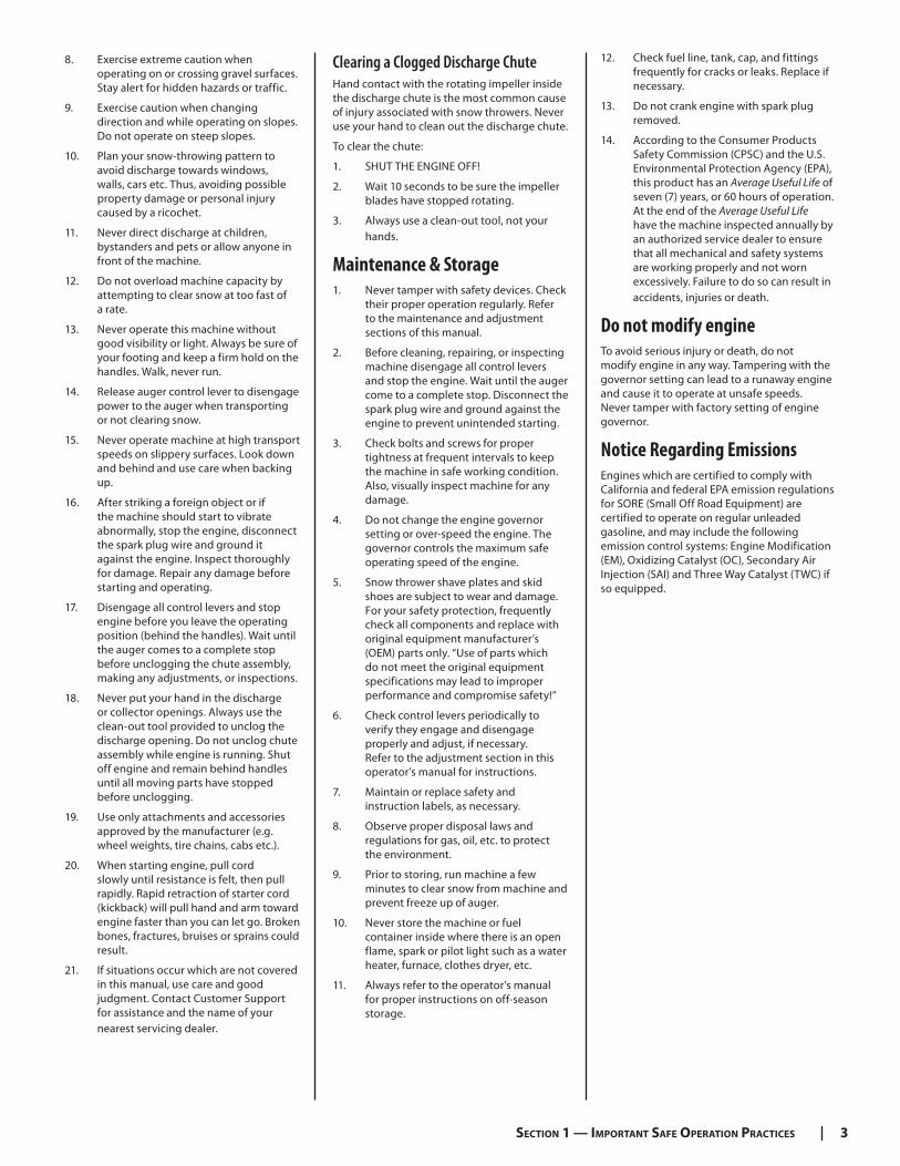
Clearing a Clogged Discharge ChuteHand contact with the rotating impeller inside the discharge chute is the most common cause of injury associated with snow throwers. Never use your hand to clean out the discharge chute.
To clear the chute:
1. SHUT THE ENGINE OFF!
2. Wait 10 seconds to be sure the impeller blades have stopped rotating.
3. Always use a clean-out tool, not your hands.
Maintenance & Storage1. Never tamper with safety devices. Check
their proper operation regularly. Refer to the maintenance and adjustment sections of this manual.
2. Before cleaning, repairing, or inspecting machine disengage all control levers and stop the engine. Wait until the auger come to a complete stop. Disconnect the spark plug wire and ground against the engine to prevent unintended starting.
3. Check bolts and screws for proper tightness at frequent intervals to keep the machine in safe working condition. Also, visually inspect machine for any damage.
4. Do not change the engine governor setting or over-speed the engine. The governor controls the maximum safe operating speed of the engine.
5. Snow thrower shave plates and skid shoes are subject to wear and damage. For your safety protection, frequently check all components and replace with original equipment manufacturer’s (OEM) parts only. “Use of parts which do not meet the original equipment specifications may lead to improper performance and compromise safety!”
6. Check control levers periodically to verify they engage and disengage properly and adjust, if necessary. Refer to the adjustment section in this operator’s manual for instructions.
7. Maintain or replace safety and instruction labels, as necessary.
8. Observe proper disposal laws and regulations for gas, oil, etc. to protect the environment.
9. Prior to storing, run machine a few minutes to clear snow from machine and prevent freeze up of auger.
10. Never store the machine or fuel container inside where there is an open flame, spark or pilot light such as a water heater, furnace, clothes dryer, etc.
11. Always refer to the operator’s manual for proper instructions on off-season storage.
12. Check fuel line, tank, cap, and fittings frequently for cracks or leaks. Replace if necessary.
13. Do not crank engine with spark plug removed.
14. According to the Consumer Products Safety Commission (CPSC) and the U.S. Environmental Protection Agency (EPA), this product has an Average Useful Life of seven (7) years, or 60 hours of operation. At the end of the Average Useful Life have the machine inspected annually by an authorized service dealer to ensure that all mechanical and safety systems are working properly and not worn excessively. Failure to do so can result in accidents, injuries or death.
Do not modify engineTo avoid serious injury or death, do not modify engine in any way. Tampering with the governor setting can lead to a runaway engine and cause it to operate at unsafe speeds. Never tamper with factory setting of engine governor.
Notice Regarding EmissionsEngines which are certified to comply with California and federal EPA emission regulations for SORE (Small Off Road Equipment) are certified to operate on regular unleaded gasoline, and may include the following emission control systems: Engine Modification (EM), Oxidizing Catalyst (OC), Secondary Air Injection (SAI) and Three Way Catalyst (TWC) if so equipped.
4 SECTION 1 — IMPORTANT SAFE OPERATION PRACTICES
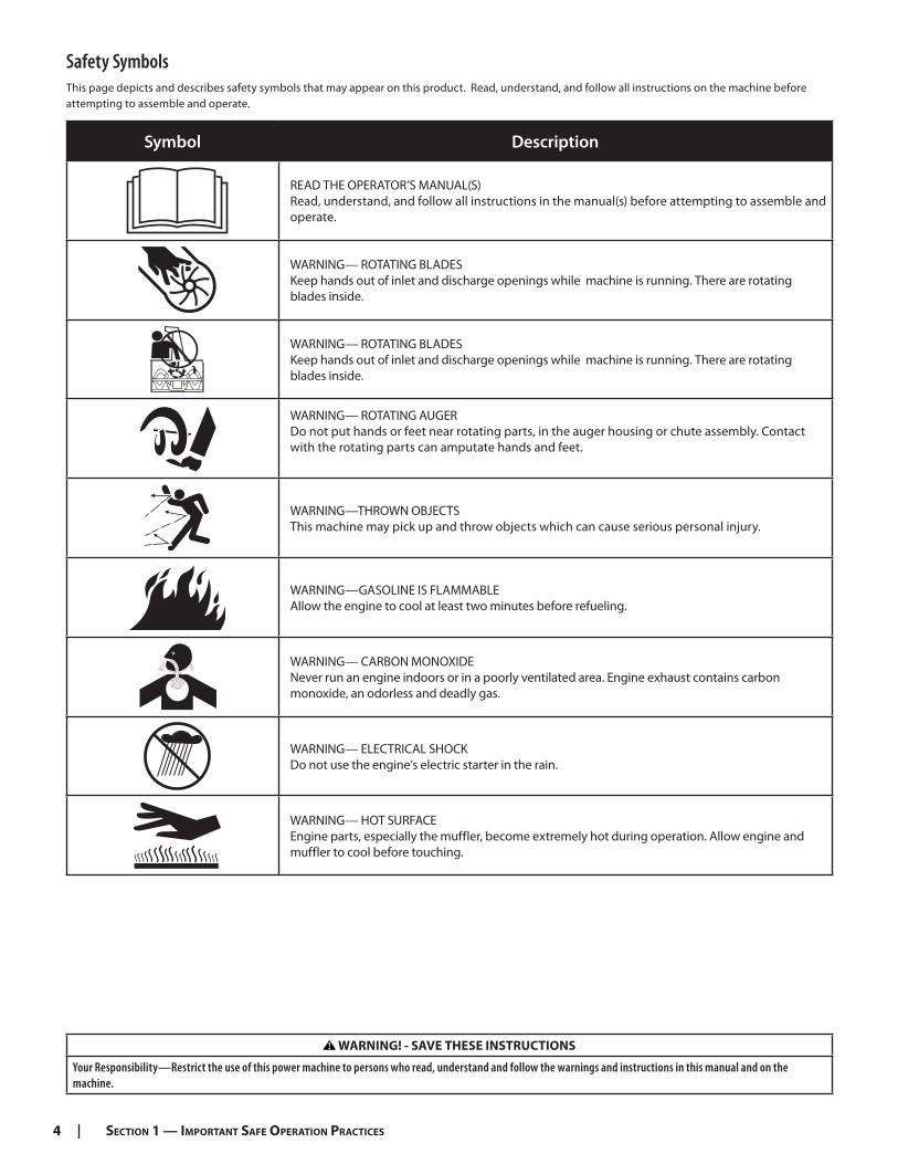
Safety SymbolsThis page depicts and describes safety symbols that may appear on this product. Read, understand, and follow all instructions on the machine before attempting to assemble and operate.
Symbol Description
READ THE OPERATOR’S MANUAL(S) Read, understand, and follow all instructions in the manual(s) before attempting to assemble and operate.
WARNING— ROTATING BLADES Keep hands out of inlet and discharge openings while machine is running. There are rotating blades inside.
WARNING— ROTATING BLADES Keep hands out of inlet and discharge openings while machine is running. There are rotating blades inside.
WARNING— ROTATING AUGER Do not put hands or feet near rotating parts, in the auger housing or chute assembly. Contact with the rotating parts can amputate hands and feet.
WARNING—THROWN OBJECTS This machine may pick up and throw objects which can cause serious personal injury.
WARNING—GASOLINE IS FLAMMABLE Allow the engine to cool at least two minutes before refueling.
WARNING— CARBON MONOXIDENever run an engine indoors or in a poorly ventilated area. Engine exhaust contains carbon monoxide, an odorless and deadly gas.
WARNING— ELECTRICAL SHOCK Do not use the engine’s electric starter in the rain.
WARNING— HOT SURFACE Engine parts, especially the muffler, become extremely hot during operation. Allow engine and muffler to cool before touching.
WARNING! - SAVE THESE INSTRUCTIONS
Your Responsibility—Restrict the use of this power machine to persons who read, understand and follow the warnings and instructions in this manual and on the machine.
5
Assembly & Set-Up 2
Thank you for purchasing this product. It was carefully engineered to provide excellent performance when properly operated and maintained.
Please read this entire manual prior to operating the equipment. It instructs you how to safely and easily set up, operate and maintain your machine. Please be sure that you, and any other persons who will operate the machine, carefully follow the recommended safety practices at all times. Failure to do so could result in personal injury or property damage.
All information in this manual is relative to the most recent product information available at the time of printing. Review this manual frequently to familiarize yourself with the machine, its features and operation. Please be aware that this Operator’s Manual may cover a range of product specifications for various models. Characteristics and features discussed
and/or illustrated in this manual may not be applicable to all models. We reserve the right to change product specifications, designs and equipment without notice and without incurring obligation.
If applicable, the power testing information used to establish the power rating of the engine equipped on this machine can be found at www.opei.org or the engine manufacturer’s web site.
If you have any problems or questions concerning the machine, phone your local authorized service dealer or contact us directly. We want to ensure your complete satisfaction at all times.
Throughout this manual, all references to right and left side of the machine are observed from the operating position.
Thank You
Contents of Carton
• Snow Thrower (1) • Chute Assembly (1) • Chute Control Rod, Flex Shaft, or Side
• Replacement Auger Shear Pins (2-4) • Safety Key (2) Crank Rod Assembly† (1)
• Snow Thrower Operator’s Manual (1) • Engine Operator’s Manual (1) • Parts/Warranty Document (1)
• Carriage Screw† (2) • Flange Lock Nut† (2) • Product Registration Card (1)
† If Equipped
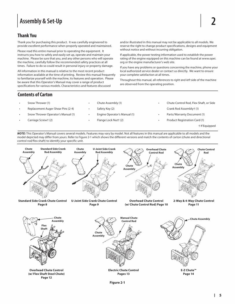
NOTE: This Operator’s Manual covers several models. Features may vary by model. Not all features in this manual are applicable to all models and the model depicted may differ from yours. Refer to Figure 2-1 which shows the different versions and match the contents of carton (chute and directional control rod/flex shaft) to identify your specific unit.
Overhead Chute Control
(w/ Flex Shaft Steel Chute)
Page 12
Electric Chute Control
Pages 13
Manual Chute
Control Rod
Chute
Assembly
Chute
Assembly
Flex
Shaft
E-Z Chute™Page 14
Chute Assembly
U-Joint Side Crank Chute Control
Page 9
2-Way & 4-Way Chute Control
Page 11
Overhead Chute Control
(w/ Chute Control Rod) Page 10
Standard Side Crank Chute Control
Page 8
Standard Side Crank
Rod Assembly
U-Joint Side Crank
Rod AssemblyOverhead Chute
Control Rod
Chute Control
Rod
Chute
Assembly
Chute
Assembly
Chute
Assembly
Chute
Assembly
Figure 2-1
6 SECTION 2 — ASSEMBLY & SET-UP
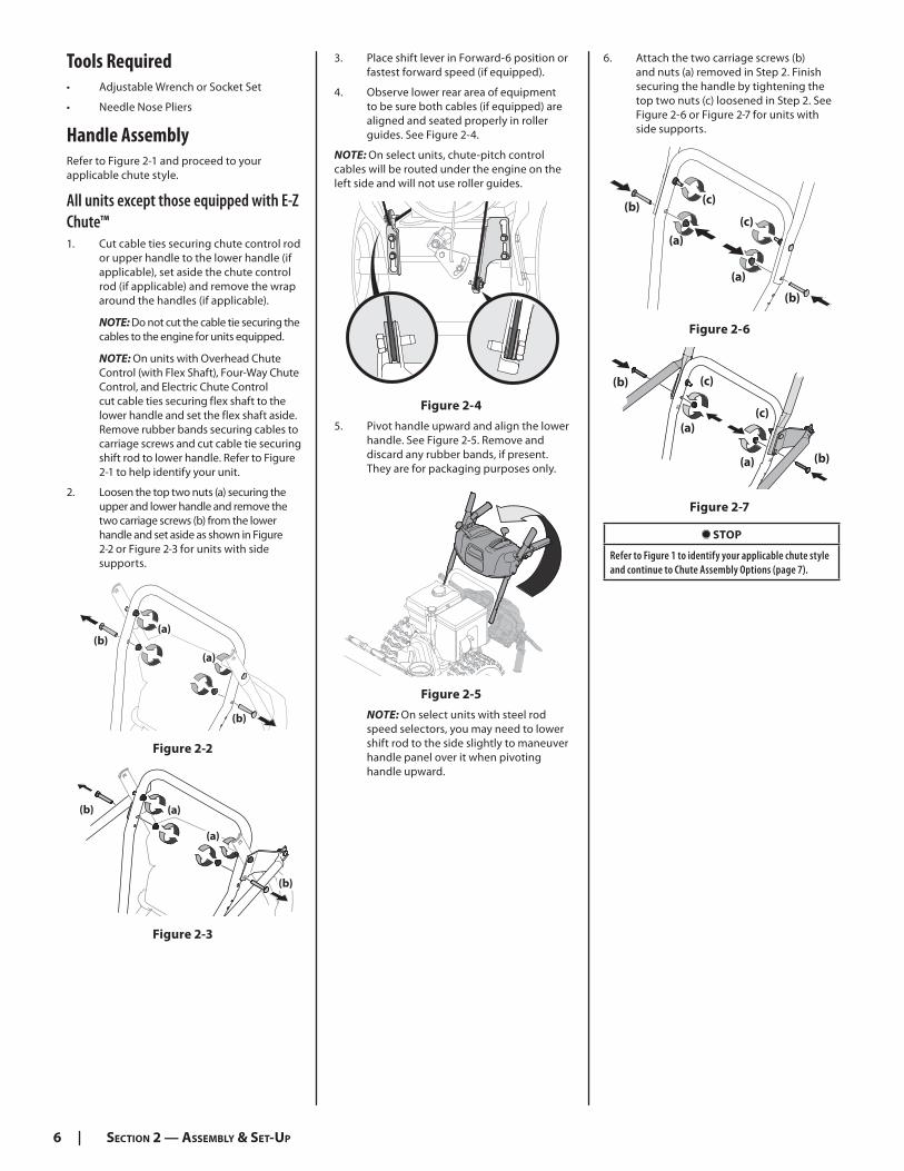
Tools Required• Adjustable Wrench or Socket Set
• Needle Nose Pliers
Handle AssemblyRefer to Figure 2-1 and proceed to your applicable chute style.
All units except those equipped with E-Z Chute™1. Cut cable ties securing chute control rod
or upper handle to the lower handle (if applicable), set aside the chute control rod (if applicable) and remove the wrap around the handles (if applicable).
NOTE: Do not cut the cable tie securing the cables to the engine for units equipped.
NOTE: On units with Overhead Chute Control (with Flex Shaft), Four-Way Chute Control, and Electric Chute Control cut cable ties securing flex shaft to the lower handle and set the flex shaft aside. Remove rubber bands securing cables to carriage screws and cut cable tie securing shift rod to lower handle. Refer to Figure 2-1 to help identify your unit.
2. Loosen the top two nuts (a) securing the upper and lower handle and remove the two carriage screws (b) from the lower handle and set aside as shown in Figure 2-2 or Figure 2-3 for units with side supports.
(a)
(a)(b)
(b)
Figure 2-2
(a)
(a)
(b)
(b)
Figure 2-3
3. Place shift lever in Forward-6 position or fastest forward speed (if equipped).
4. Observe lower rear area of equipment to be sure both cables (if equipped) are aligned and seated properly in roller guides. See Figure 2-4.
NOTE: On select units, chute-pitch control cables will be routed under the engine on the left side and will not use roller guides.
Figure 2-4
5. Pivot handle upward and align the lower handle. See Figure 2-5. Remove and discard any rubber bands, if present. They are for packaging purposes only.
Figure 2-5
NOTE: On select units with steel rod speed selectors, you may need to lower shift rod to the side slightly to maneuver handle panel over it when pivoting handle upward.
6. Attach the two carriage screws (b) and nuts (a) removed in Step 2. Finish securing the handle by tightening the top two nuts (c) loosened in Step 2. See Figure 2-6 or Figure 2-7 for units with side supports.
(c)
(c)
(b)
(b)
(a)
(a)
Figure 2-6
(c)
(c)
(a)
(a) (b)
(b)
Figure 2-7
STOP
Refer to Figure 1 to identify your applicable chute style and continue to Chute Assembly Options (page 7).
7SECTION 2 — ASSEMBLY & SET-UP
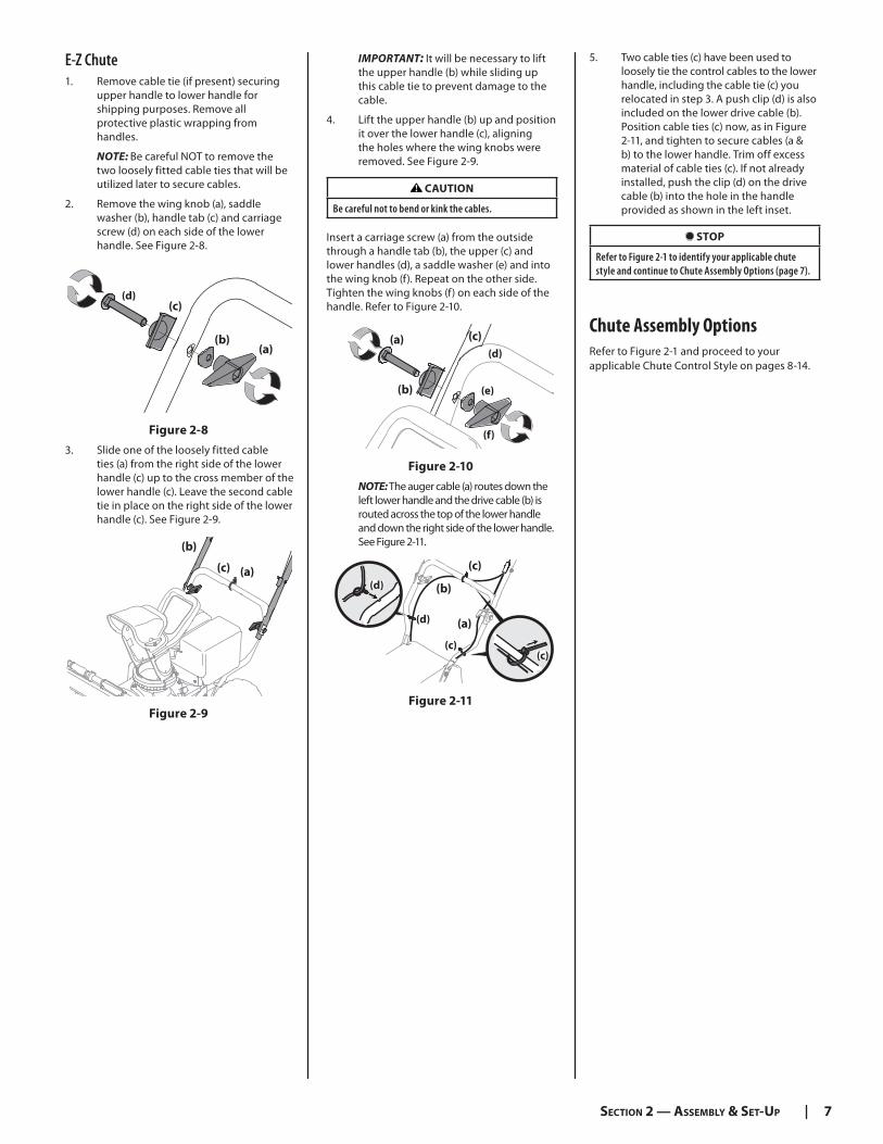
IMPORTANT: It will be necessary to lift the upper handle (b) while sliding up this cable tie to prevent damage to the cable.
4. Lift the upper handle (b) up and position it over the lower handle (c), aligning the holes where the wing knobs were removed. See Figure 2-9.
CAUTION
Be careful not to bend or kink the cables. Insert a carriage screw (a) from the outside through a handle tab (b), the upper (c) and lower handles (d), a saddle washer (e) and into the wing knob (f). Repeat on the other side. Tighten the wing knobs (f) on each side of the handle. Refer to Figure 2-10.
(c)
(e)(b)
(a)(d)
(f)
Figure 2-10
NOTE: The auger cable (a) routes down the left lower handle and the drive cable (b) is routed across the top of the lower handle and down the right side of the lower handle. See Figure 2-11.
(c)
(d)
(c)
(b)
(a)
(c)
(d)
Figure 2-11
5. Two cable ties (c) have been used to loosely tie the control cables to the lower handle, including the cable tie (c) you relocated in step 3. A push clip (d) is also included on the lower drive cable (b). Position cable ties (c) now, as in Figure 2-11, and tighten to secure cables (a & b) to the lower handle. Trim off excess material of cable ties (c). If not already installed, push the clip (d) on the drive cable (b) into the hole in the handle provided as shown in the left inset.
STOP
Refer to Figure 2-1 to identify your applicable chute style and continue to Chute Assembly Options (page 7).
Chute Assembly Options
Refer to Figure 2-1 and proceed to your applicable Chute Control Style on pages 8-14.
E-Z Chute1. Remove cable tie (if present) securing
upper handle to lower handle for shipping purposes. Remove all protective plastic wrapping from handles.
NOTE: Be careful NOT to remove the two loosely fitted cable ties that will be utilized later to secure cables.
2. Remove the wing knob (a), saddle washer (b), handle tab (c) and carriage screw (d) on each side of the lower handle. See Figure 2-8.
(c)
(b)(a)
(d)
Figure 2-8
3. Slide one of the loosely fitted cable ties (a) from the right side of the lower handle (c) up to the cross member of the lower handle (c). Leave the second cable tie in place on the right side of the lower handle (c). See Figure 2-9.
(c)
(b)
(a)
Figure 2-9
8 SECTION 2 — ASSEMBLY & SET-UP
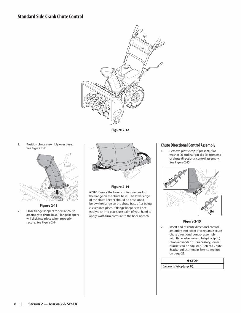
Chute Directional Control Assembly1. Remove plastic cap (if present), flat
washer (a) and hairpin clip (b) from end of chute directional control assembly. See Figure 2-15.
(a)
(b)
Figure 2-15
2. Insert end of chute directional control assembly into lower bracket and secure chute directional control assembly with flat washer (a) and hairpin clip (b) removed in Step 1. If necessary, lower bracket can be adjusted. Refer to Chute Bracket Adjustment in Service section on page 25.
STOP
Continue to Set-Up (page 14).
Figure 2-14
NOTE: Ensure the lower chute is secured to the flange on the chute base. The lower edge of the chute keeper should be positioned below the flange on the chute base after being clicked into place. If flange keepers will not easily click into place, use palm of your hand to apply swift, firm pressure to the back of each.
1. Position chute assembly over base. See Figure 2-13.
Figure 2-13
2. Close flange keepers to secure chute assembly to chute base. Flange keepers will click into place when properly secure. See Figure 2-14.
Standard Side Crank Chute Control
Figure 2-12

9SECTION 2 — ASSEMBLY & SET-UP
U-Joint Side Crank Chute Control
Figure 2-16
1. Position chute assembly over base. See Figure 2-17.
Figure 2-17
2. Close flange keepers to secure chute assembly to chute base. Flange keepers will click into place when properly secure. See Figure 2-18.
Figure 2-18
NOTE: Ensure the lower chute is secured to the flange on the chute base. The lower edge of the chute keeper should be positioned below the flange on the chute base after being clicked into place. If flange keepers will not easily click into place, use palm of your hand to apply swift, firm pressure to the back of each.
Chute Directional Control Assembly1. Remove cotter pin from end of
unattached chute directional control assembly.
2. Insert unattached chute directional control assembly into eye bolt on left side of handle assembly. See Figure 2-19.
(a)
Figure 2-19
3. Line up holes in the end of unattached chute directional control assembly with holes in U-joint attached to lower chute directional control assembly. Insert cotter pin (a). See Figure 2-19. If necessary, bracket securing lower chute directional control assembly to chute base can be adjusted. Refer to Chute Bracket Adjustment in Service section on page 25.
STOP
Continue to Set-Up (page 14).
10 SECTION 2 — ASSEMBLY & SET-UP
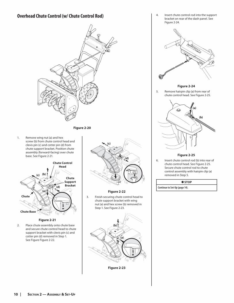
Overhead Chute Control (w/ Chute Control Rod)
Figure 2-20
1. Remove wing nut (a) and hex screw (b) from chute control head and clevis pin (c) and cotter pin (d) from chute support bracket. Position chute assembly (forward-facing) over chute base. See Figure 2-21.
(a)
(b)(c)
(d)
Chute
Support
Bracket
Chute Control
Head
Chute
Chute Base
Figure 2-21
2. Place chute assembly onto chute base and secure chute control head to chute support bracket with clevis pin (c) and cotter pin (d) removed in Step 1. See Figure Figure 2-22.
(c)
(d)
Figure 2-22
3. Finish securing chute control head to chute support bracket with wing nut (a) and hex screw (b) removed in Step 1. See Figure 2-23.
(a)
(b)
Figure 2-23
4. Insert chute control rod into the support bracket on rear of the dash panel. See Figure 2-24.
Figure 2-24
5. Remove hairpin clip (a) from rear of chute control head. See Figure 2-25.
(a)
(b)
Figure 2-25
6. Insert chute control rod (b) into rear of chute control head. See Figure 2-25. Secure chute control rod to chute control assembly with hairpin clip (a) removed in Step 5.
STOP
Continue to Set-Up (page 14).

11SECTION 2 — ASSEMBLY & SET-UP
2-Way & 4-Way Chute Control
Figure 2-26
1. Remove hairpin clip (a), wing nut (b) and hex screw (c) from chute control head and clevis pin (d) and bow-tie cotter pin (e) from chute support bracket. See Figure 2-27.
(a)
(b)
(c)
(d)
Chute Control Head
Chute
Chute
Support
Bracket
Chute Base
(e)
Figure 2-27
NOTE: For smoothest operation, cables should all be to the left of the chute directional control rod.
2. Insert chute control rod into chute control head. Push rod as far into chute control head as possible, keeping holes in rod pointing upward. See Figure 2-28.
Figure 2-28
3. Place chute onto chute base and ensure chute control rod is positioned under handle panel. Install hex screw (c) removed in Step 1, but do not secure with wing nut at this time. See Figure 2-29.
(c)
Figure 2-29
4. Squeeze trigger on joystick and rotate chute by hand to face forward. The holes in chute control input will be facing up. See Figure 2-30.
Chute Control InputTop View
Joystick
Figure 2-30
NOTE: Chute will not rotate without squeezing trigger on joystick.
5. Rotate joystick to one o’clock position so that indicator arrow on pinion gear below control panel faces upward. See Figure 2-31.
Figure 2-31
6. Insert chute control rod into pinion gear below joystick. Make sure to line up hole in rod with arrow on pinion gear. See Figure 2-32.
Figure 2-32
NOTE: Chute control rod will fit snug into pinion gear. Support rear of dash panel with one hand while inserting rod with your other hand to ensure rod is inserted all the way into pinion gear.
NOTE: The hole in the chute directional control rod is a reference for aligning rod with indicator arrow on pinion gear, and will be visible after rod has been inserted.

12 SECTION 2 — ASSEMBLY & SET-UP
7. Push chute control rod toward control panel until hole in rod lines up with hole in chute control input closest to chute control head and insert hairpin clip (a)removed in Step 1. See Figure 2-33.
(a)
Figure 2-33
NOTE: Second hole is used to achieve further engagement of chute control rod into pinion gear if required. Refer to Service section for Chute Control Rod adjustments.
8. Finish securing chute control head to chute support bracket with wing nut (b), clevis pin (d), and bow-tie cotter pin (e) removed in Step 1.
STOP
Continue to Set-Up (page 14)
Overhead Chute Control (w/ Flex Shaft & Steel Chute)
Figure 2-34
1. Remove lock nuts (a) and hex screws (b)from chute support bracket (this will require two wrenches). See Figure 2-35.
Chute
Assembly
Chute Base
Chute Support
Bracket
Chute Control Head
(a)
(a)
(b)
(b)
Figure 2-35
2. Place chute assembly onto chute base and chute control head onto chute support bracket. See Figure 2-36.
3. Secure chute control head to chute support bracket with lock nuts (a) and hex screws (b) removed in Step 1. See Figure 2-36.
(a)
(a)
(b)
(b)
Figure 2-36
NOTE: For smoothest operation, cables should all be to the left of the chute directional control rod.
4. Remove hairpin clip (a) from rear of chute control assembly. See Figure 2-37.
(a)
(b)
Figure 2-37
13SECTION 2 — ASSEMBLY & SET-UP
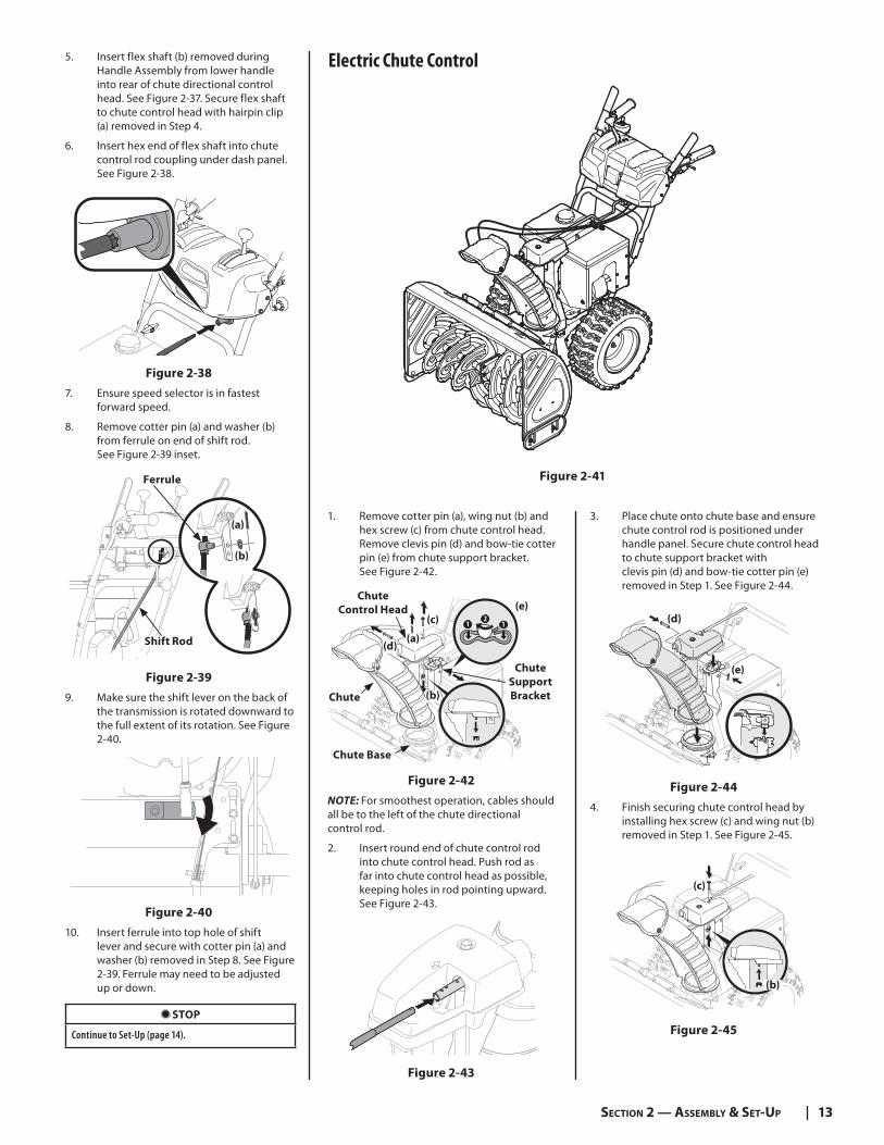
5. Insert flex shaft (b) removed during Handle Assembly from lower handle into rear of chute directional control head. See Figure 2-37. Secure flex shaft to chute control head with hairpin clip (a) removed in Step 4.
6. Insert hex end of flex shaft into chute control rod coupling under dash panel. See Figure 2-38.
Figure 2-38
7. Ensure speed selector is in fastest forward speed.
8. Remove cotter pin (a) and washer (b) from ferrule on end of shift rod. See Figure 2-39 inset.
(a)
(b)
Shift Rod
Ferrule
Figure 2-39
9. Make sure the shift lever on the back of the transmission is rotated downward to the full extent of its rotation. See Figure 2-40.
Figure 2-40
10. Insert ferrule into top hole of shift lever and secure with cotter pin (a) and washer (b) removed in Step 8. See Figure 2-39. Ferrule may need to be adjusted up or down.
STOP
Continue to Set-Up (page 14).
Electric Chute Control
Figure 2-41
1. Remove cotter pin (a), wing nut (b) and hex screw (c) from chute control head. Remove clevis pin (d) and bow-tie cotter pin (e) from chute support bracket. See Figure 2-42.
(c)
(e)
1 12
Chute
Chute
Support
Bracket
Chute Base
(a)(d)
(b)
Chute
Control Head
Figure 2-42
NOTE: For smoothest operation, cables should all be to the left of the chute directional control rod.
2. Insert round end of chute control rod into chute control head. Push rod as far into chute control head as possible, keeping holes in rod pointing upward. See Figure 2-43.
Figure 2-43
3. Place chute onto chute base and ensure chute control rod is positioned under handle panel. Secure chute control head to chute support bracket with clevis pin (d) and bow-tie cotter pin (e) removed in Step 1. See Figure 2-44.
(d)
(e)
Figure 2-44
4. Finish securing chute control head by installing hex screw (c) and wing nut (b) removed in Step 1. See Figure 2-45.
(c)
(b)
Figure 2-45

14 SECTION 2 — ASSEMBLY & SET-UP
5. Insert other end of chute control rod into coupler below handle panel. Make sure to line up flat end of rod and flat end of coupler. You may need to rotate rod around until these two surfaces line up. See Figure 2-46 inset.
Figure 2-46
6. Push chute control rod toward the control panel until hole in rod lines up with middle hole in chute control input and insert cotter pin (a) removed in Step 1. See Figure 2-47.
(a)
Figure 2-47
NOTE: There is a reference hole provided at rear end of control rod to help know when holes are vertical.
NOTE: Hole furthest from chute control head is used to achieve further engagement of chute control rod into coupler if required. Refer to Service section for Chute Control Rod adjustment on page 25. Hole closest to chute control head is used for manual movement of chute assembly if required. Refer to Controls & Operation section on page 18.
STOP
Continue to Set-Up (page 14)
E-Z Chute Control™
Figure 2-48
STOP
Continue to Set-Up (page 14)
Set-Up
Chute Control Cable Routing (If Equipped)For units equipped with 2-way or 4-way chute control joystick, electric chute control and/or chute-pitch controls, ensure control cables are routed properly.
Chute control cables are routed through a single wire guide (a) on top of the engine and/or through two wire guides (b) located on the left side of the unit.
NOTE: For smoothest operation, cables should all be to the left of the chute directional control rod.
NOTE: The number of cables routed through the wire guides will depend on unit model.
1. Locate cable guide(s) and perform the following:
• Units with Top Mounted Wire Guide (a) - Check that all cables are properly routed through cable guide on top of engine. See Figure 2-49.
• Units with Side Mounted Wire Guides (b) - Check that all cables are properly routed through the wire guide below the left side of the engine and the wire guide below the chute control head. See Figure 2-49.
(b)
(a)
(c)
(c)
Figure 2-49
The E-Z Chute™ does not require any installation.
15SECTION 2 — ASSEMBLY & SET-UP
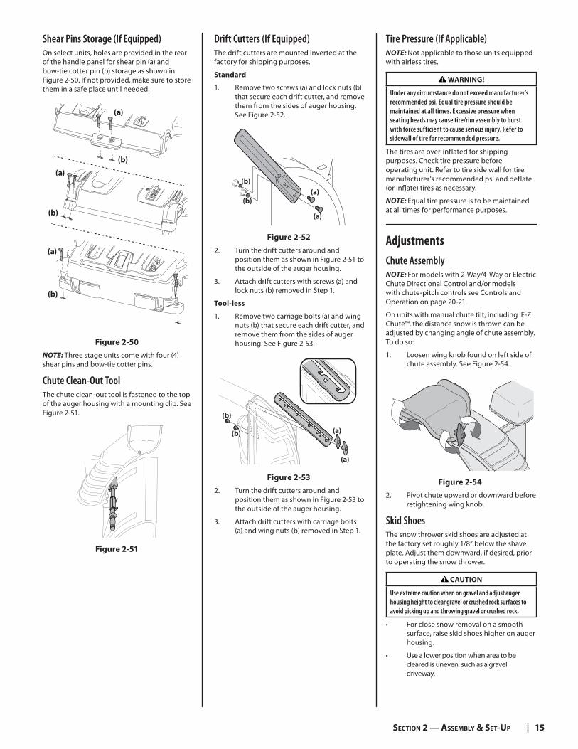
Shear Pins Storage (If Equipped)On select units, holes are provided in the rear of the handle panel for shear pin (a) and bow-tie cotter pin (b) storage as shown in Figure 2-50. If not provided, make sure to store them in a safe place until needed.
(a)
(b)
(a)
(b)
(a)
(b)
Figure 2-50
NOTE: Three stage units come with four (4) shear pins and bow-tie cotter pins.
Chute Clean-Out ToolThe chute clean-out tool is fastened to the top of the auger housing with a mounting clip. See Figure 2-51.
Figure 2-51
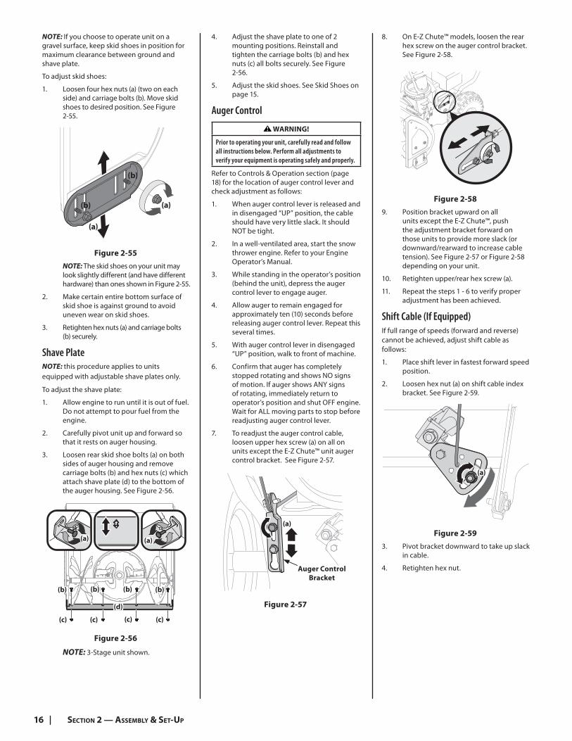
Drift Cutters (If Equipped)The drift cutters are mounted inverted at the factory for shipping purposes.
Standard
1. Remove two screws (a) and lock nuts (b)that secure each drift cutter, and remove them from the sides of auger housing. See Figure 2-52.
(a)
(a)
(b)
(b)
Figure 2-52
2. Turn the drift cutters around and position them as shown in Figure 2-51 to the outside of the auger housing.
3. Attach drift cutters with screws (a) and lock nuts (b) removed in Step 1.
Tool-less
1. Remove two carriage bolts (a) and wing nuts (b) that secure each drift cutter, and remove them from the sides of auger housing. See Figure 2-53.
(b)
(b) (a)
(a)
Figure 2-53
2. Turn the drift cutters around and position them as shown in Figure 2-53 to the outside of the auger housing.
3. Attach drift cutters with carriage bolts (a) and wing nuts (b) removed in Step 1.
Tire Pressure (If Applicable)NOTE: Not applicable to those units equipped with airless tires.
WARNING!
Under any circumstance do not exceed manufacturer’s recommended psi. Equal tire pressure should be maintained at all times. Excessive pressure when seating beads may cause tire/rim assembly to burst with force sufficient to cause serious injury. Refer to sidewall of tire for recommended pressure.
The tires are over-inflated for shipping purposes. Check tire pressure before operating unit. Refer to tire side wall for tire manufacturer’s recommended psi and deflate (or inflate) tires as necessary.
NOTE: Equal tire pressure is to be maintained at all times for performance purposes.
Adjustments
Chute Assembly NOTE: For models with 2-Way/4-Way or Electric Chute Directional Control and/or models with chute-pitch controls see Controls and Operation on page 20-21.
On units with manual chute tilt, including E-Z Chute™, the distance snow is thrown can be adjusted by changing angle of chute assembly. To do so:
1. Loosen wing knob found on left side of chute assembly. See Figure 2-54.
Figure 2-54
2. Pivot chute upward or downward before retightening wing knob.
Skid ShoesThe snow thrower skid shoes are adjusted at the factory set roughly 1/8” below the shave plate. Adjust them downward, if desired, prior to operating the snow thrower.
CAUTION
Use extreme caution when on gravel and adjust auger housing height to clear gravel or crushed rock surfaces to avoid picking up and throwing gravel or crushed rock.
• For close snow removal on a smooth surface, raise skid shoes higher on auger housing.
• Use a lower position when area to be cleared is uneven, such as a gravel driveway.
16 SECTION 2 — ASSEMBLY & SET-UP
NOTE: If you choose to operate unit on a gravel surface, keep skid shoes in position for maximum clearance between ground and shave plate.
To adjust skid shoes:
1. Loosen four hex nuts (a) (two on each side) and carriage bolts (b). Move skid shoes to desired position. See Figure 2-55.
(a)
(a)
(b)
(b)
Figure 2-55
NOTE: The skid shoes on your unit may look slightly different (and have different hardware) than ones shown in Figure 2-55.
2. Make certain entire bottom surface of skid shoe is against ground to avoid uneven wear on skid shoes.
3. Retighten hex nuts (a) and carriage bolts (b) securely.
Shave PlateNOTE: this procedure applies to units equipped with adjustable shave plates only.
To adjust the shave plate:
1. Allow engine to run until it is out of fuel. Do not attempt to pour fuel from the engine.
2. Carefully pivot unit up and forward so that it rests on auger housing.
3. Loosen rear skid shoe bolts (a) on both sides of auger housing and remove carriage bolts (b) and hex nuts (c) which attach shave plate (d) to the bottom of the auger housing. See Figure 2-56.
(a)(a)
(b)(b)(b)(b)
(c) (c)(c)(c)
(d)
Figure 2-56
NOTE: 3-Stage unit shown.
4. Adjust the shave plate to one of 2 mounting positions. Reinstall and tighten the carriage bolts (b) and hex nuts (c) all bolts securely. See Figure 2-56.
5. Adjust the skid shoes. See Skid Shoes on page 15.
Auger Control
WARNING!
Prior to operating your unit, carefully read and follow all instructions below. Perform all adjustments to verify your equipment is operating safely and properly.
Refer to Controls & Operation section (page 18) for the location of auger control lever and check adjustment as follows:
1. When auger control lever is released and in disengaged “UP” position, the cable should have very little slack. It should NOT be tight.
2. In a well-ventilated area, start the snow thrower engine. Refer to your Engine Operator’s Manual.
3. While standing in the operator’s position (behind the unit), depress the auger control lever to engage auger.
4. Allow auger to remain engaged for approximately ten (10) seconds before releasing auger control lever. Repeat this several times.
5. With auger control lever in disengaged “UP” position, walk to front of machine.
6. Confirm that auger has completely stopped rotating and shows NO signs of motion. If auger shows ANY signs of rotating, immediately return to operator’s position and shut OFF engine. Wait for ALL moving parts to stop before readjusting auger control lever.
7. To readjust the auger control cable, loosen upper hex screw (a) on all on units except the E-Z Chute™ unit auger control bracket. See Figure 2-57.
Auger Control
Bracket
(a)
Figure 2-57
8. On E-Z Chute™ models, loosen the rear hex screw on the auger control bracket. See Figure 2-58.
Figure 2-58
9. Position bracket upward on all units except the E-Z Chute™, push the adjustment bracket forward on those units to provide more slack (or downward/rearward to increase cable tension). See Figure 2-57 or Figure 2-58 depending on your unit.
10. Retighten upper/rear hex screw (a).
11. Repeat the steps 1 - 6 to verify proper adjustment has been achieved.
Shift Cable (If Equipped)If full range of speeds (forward and reverse) cannot be achieved, adjust shift cable as follows:
1. Place shift lever in fastest forward speed position.
2. Loosen hex nut (a) on shift cable index bracket. See Figure 2-59.
(a)
Figure 2-59
3. Pivot bracket downward to take up slack in cable.
4. Retighten hex nut.
17SECTION 2 — ASSEMBLY & SET-UP
Shift Rod (If Equipped)If full range of speeds (forward and reverse) cannot be achieved, adjust shift rod as follows:
1. Place shift lever in fastest forward speed position.
2. Remove cotter pin (a) and washer (b) from adjustment ferrule on shift rod and pull it out from shift lever. See Figure 2-60.
(a)
(b)
Figure 2-60
3. Pivot shift bracket downward as far as it will go. See Figure 2-61.
Figure 2-61
4. Rotate ferrule up or down on shift rod as necessary until it lines up with upper hole in shift lever. Refer to Figure 2-60 inset.
5. Insert the ferrule into the upper hole and secure with the washer and cotter pin.
Drive Control (Models with out Hydro Transmission) (If Equipped)NOTE: Drive control on units with E-Z Chute™ is non-adjustable.
When drive control lever is released and in disengaged “UP” position, cable should have very little slack. It should NOT be tight.
NOTE: If excessive slack is present in drive cable or if unit’s drive is disengaging intermittently during operation, the cable may be in need of adjustment.
Check adjustment of drive control levers follows:
1. With drive control lever released, push unit gently forward. It should roll freely.
2. Engage drive control lever and gently attempt to push the unit forward. The wheels should not turn. The unit should not roll freely.
3. If equipped with a shift lever, with drive control lever released, move shift lever back and forth between the R2 position and the F6 position several times. There should be no resistance in the shift lever.
If any of the above tests failed, the drive cable is in need of adjustment. Proceed as follows:
1. Shut OFF engine. Refer to the Engine Operator’s Manual.
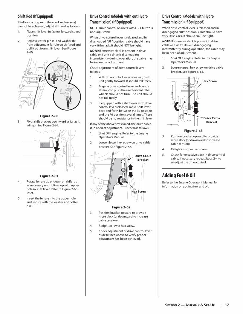
2. Loosen lower hex screw on drive cable bracket. See Figure 2-62.
Drive Cable
Bracket
Hex Screw
Figure 2-62
3. Position bracket upward to provide more slack (or downward to increase cable tension).
4. Retighten lower hex screw.
5. Check adjustment of drive control lever as described above to verify proper adjustment has been achieved.
Drive Control (Models with Hydro Transmission) (If Equipped)When drive control lever is released and in disengaged “UP” position, cable should have very little slack. It should NOT be tight.
NOTE: If excessive slack is present in drive cable or if unit’s drive is disengaging intermittently during operation, the cable may be in need of adjustment.
1. Shut OFF engine. Refer to the Engine Operator’s Manual.
2. Loosen upper hex screw on drive cable bracket. See Figure 5-63.
Drive Cable
Bracket
Hex Screw
Figure 2-63
3. Position bracket upward to provide more slack (or downward to increase cable tension).
4. Retighten upper hex screw.
5. Check for excessive slack in drive control cable. If necessary repeat Steps 2-4 to re-adjust the drive control.
Adding Fuel & Oil
Refer to the Engine Operator’s Manual for information on adding fuel and oil.
18
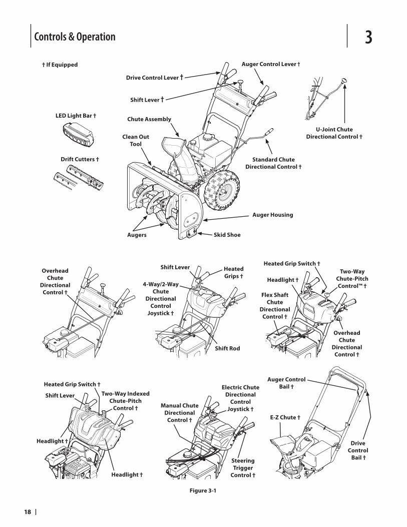
Controls & Operation 3† If Equipped
Standard Chute
Directional Control †
Shift Lever †
Augers Skid Shoe
Clean Out
Tool
Chute Assembly
Drive Control Lever †
Auger Control Lever †
Auger Housing
U-Joint Chute
Directional Control †
LED Light Bar †
Drift Cutters †
Overhead
Chute
Directional
Control †
Heated
Grips †
Shift Lever
4-Way/2-Way
Chute
Directional
Control
Joystick †
Shift Rod
Manual Chute
Directional
Control †
Electric Chute
Directional
Control
Joystick †
Steering
Trigger
Control †
Headlight †
Flex Shaft
Chute
Directional
Control †
Heated Grip Switch †
Two-Way
Chute-Pitch
Control™ †
Overhead
Chute
Directional
Control †
Shift Lever Two-Way Indexed
Chute-Pitch
Control †
Heated Grip Switch †
Headlight †
Headlight †
Drive
Control
Bail †
Auger Control
Bail †
E-Z Chute †
Figure 3-1
19SECTION 3 — CONTROLS & OPERATION
Snow thrower controls and features are described below and illustrated in Figure 3-1.
NOTE: This Operator’s Manual covers several models. Snow thrower features may vary by model. Not all features in this manual are applicable to all snow thrower models and the snow thrower depicted may differ from yours.
NOTE: All references to the left or right side of the snow thrower are from the operator’s position. Any exceptions will be noted.
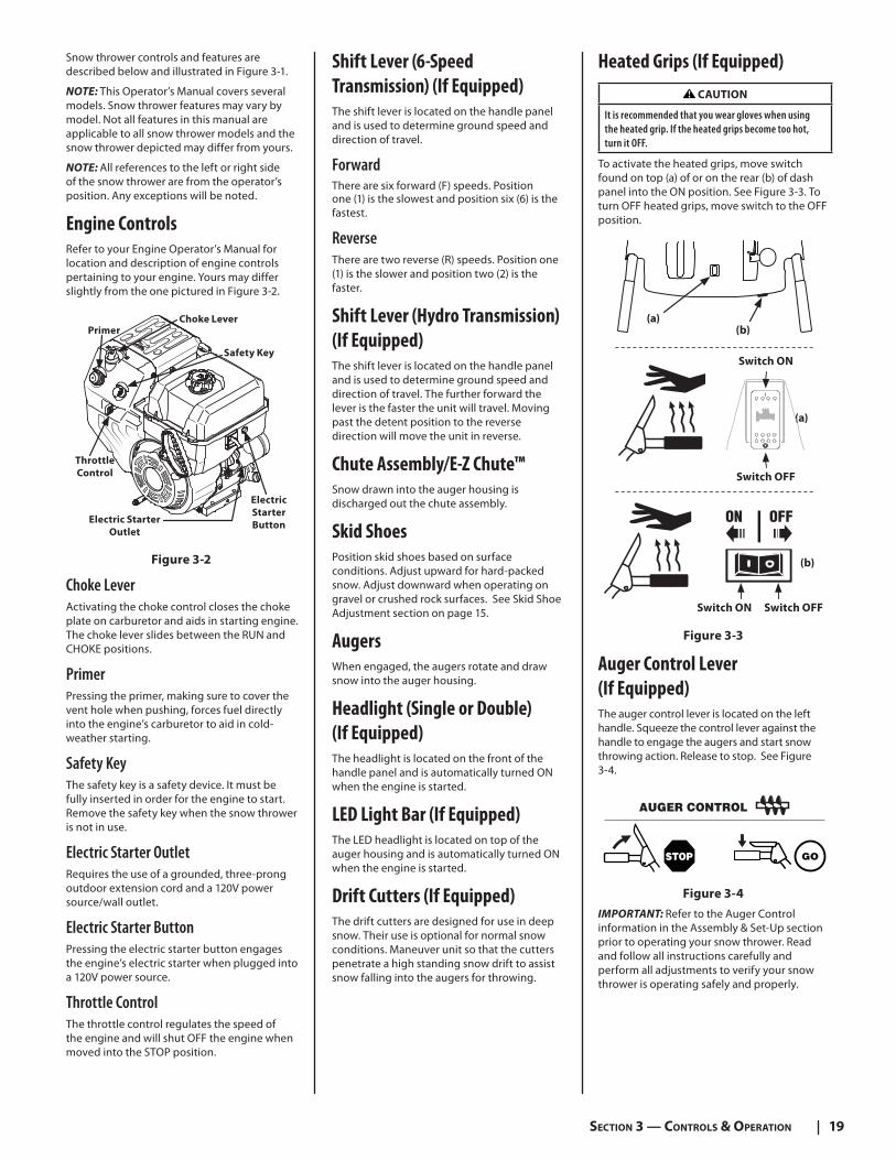
Engine ControlsRefer to your Engine Operator’s Manual for location and description of engine controls pertaining to your engine. Yours may differ slightly from the one pictured in Figure 3-2.
Choke Lever
Electric Starter
Outlet
Electric
Starter
Button
Throttle
Control
Safety Key
Primer
Figure 3-2
Choke LeverActivating the choke control closes the choke plate on carburetor and aids in starting engine. The choke lever slides between the RUN and CHOKE positions.
PrimerPressing the primer, making sure to cover the vent hole when pushing, forces fuel directly into the engine’s carburetor to aid in cold-weather starting.
Safety KeyThe safety key is a safety device. It must be fully inserted in order for the engine to start. Remove the safety key when the snow thrower is not in use.
Electric Starter OutletRequires the use of a grounded, three-prong outdoor extension cord and a 120V power source/wall outlet.
Electric Starter ButtonPressing the electric starter button engages the engine’s electric starter when plugged into a 120V power source.
Throttle ControlThe throttle control regulates the speed of the engine and will shut OFF the engine when moved into the STOP position.
Shift Lever (6-Speed
Transmission) (If Equipped)The shift lever is located on the handle panel and is used to determine ground speed and direction of travel.
ForwardThere are six forward (F) speeds. Position one (1) is the slowest and position six (6) is the fastest.
ReverseThere are two reverse (R) speeds. Position one (1) is the slower and position two (2) is the faster.
Shift Lever (Hydro Transmission)
(If Equipped)The shift lever is located on the handle panel and is used to determine ground speed and direction of travel. The further forward the lever is the faster the unit will travel. Moving past the detent position to the reverse direction will move the unit in reverse.
Chute Assembly/E-Z Chute™Snow drawn into the auger housing is discharged out the chute assembly.
Skid ShoesPosition skid shoes based on surface conditions. Adjust upward for hard-packed snow. Adjust downward when operating on gravel or crushed rock surfaces. See Skid Shoe Adjustment section on page 15.
AugersWhen engaged, the augers rotate and draw snow into the auger housing.
Headlight (Single or Double)
(If Equipped)The headlight is located on the front of the handle panel and is automatically turned ON when the engine is started.
LED Light Bar (If Equipped)The LED headlight is located on top of the auger housing and is automatically turned ON when the engine is started.
Drift Cutters (If Equipped)The drift cutters are designed for use in deep snow. Their use is optional for normal snow conditions. Maneuver unit so that the cutters penetrate a high standing snow drift to assist snow falling into the augers for throwing.
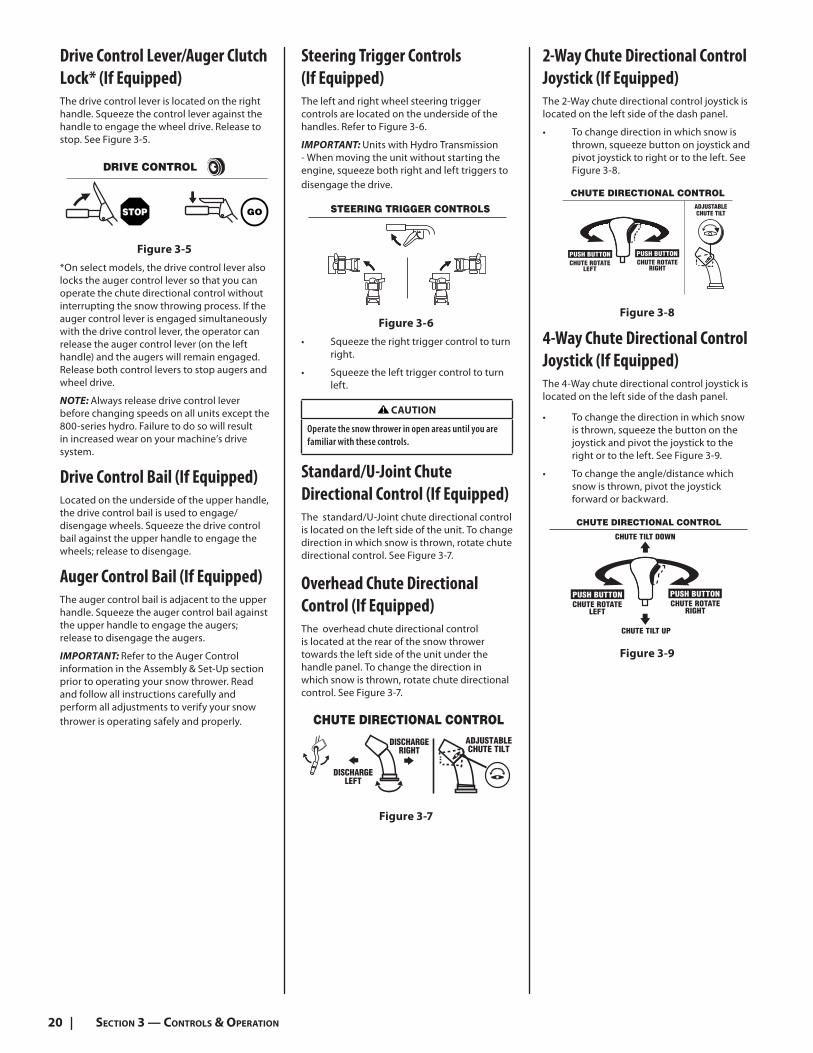
Heated Grips (If Equipped)
CAUTION
It is recommended that you wear gloves when using the heated grip. If the heated grips become too hot, turn it OFF.
To activate the heated grips, move switch found on top (a) of or on the rear (b) of dash panel into the ON position. See Figure 3-3. To turn OFF heated grips, move switch to the OFF position.
Switch ON Switch OFF
(b)
(a)(b)
(a)
Switch ON
Switch OFF
Figure 3-3
Auger Control Lever
(If Equipped)The auger control lever is located on the left handle. Squeeze the control lever against the handle to engage the augers and start snow throwing action. Release to stop. See Figure 3-4.
Figure 3-4
IMPORTANT: Refer to the Auger Control information in the Assembly & Set-Up section prior to operating your snow thrower. Read and follow all instructions carefully and perform all adjustments to verify your snow thrower is operating safely and properly.
20 SECTION 3 — CONTROLS & OPERATION
Drive Control Lever/Auger Clutch
Lock* (If Equipped)The drive control lever is located on the right handle. Squeeze the control lever against the handle to engage the wheel drive. Release to stop. See Figure 3-5.
Figure 3-5
*On select models, the drive control lever also locks the auger control lever so that you can operate the chute directional control without interrupting the snow throwing process. If the auger control lever is engaged simultaneously with the drive control lever, the operator can release the auger control lever (on the left handle) and the augers will remain engaged. Release both control levers to stop augers and wheel drive.
NOTE: Always release drive control lever before changing speeds on all units except the 800-series hydro. Failure to do so will result in increased wear on your machine’s drive system.
Drive Control Bail (If Equipped)Located on the underside of the upper handle, the drive control bail is used to engage/disengage wheels. Squeeze the drive control bail against the upper handle to engage the wheels; release to disengage.
Auger Control Bail (If Equipped)The auger control bail is adjacent to the upper handle. Squeeze the auger control bail against the upper handle to engage the augers; release to disengage the augers.
IMPORTANT: Refer to the Auger Control information in the Assembly & Set-Up section prior to operating your snow thrower. Read and follow all instructions carefully and perform all adjustments to verify your snow thrower is operating safely and properly.
Steering Trigger Controls
(If Equipped)The left and right wheel steering trigger controls are located on the underside of the handles. Refer to Figure 3-6.
IMPORTANT: Units with Hydro Transmission - When moving the unit without starting the engine, squeeze both right and left triggers to disengage the drive.
Figure 3-6
• Squeeze the right trigger control to turn right.
• Squeeze the left trigger control to turn left.
CAUTION
Operate the snow thrower in open areas until you are familiar with these controls.
Standard/U-Joint Chute
Directional Control (If Equipped)The standard/U-Joint chute directional control is located on the left side of the unit. To change direction in which snow is thrown, rotate chute directional control. See Figure 3-7.
Overhead Chute Directional
Control (If Equipped)The overhead chute directional control is located at the rear of the snow thrower towards the left side of the unit under the handle panel. To change the direction in which snow is thrown, rotate chute directional control. See Figure 3-7.
Figure 3-7
2-Way Chute Directional Control
Joystick (If Equipped)The 2-Way chute directional control joystick is located on the left side of the dash panel.
• To change direction in which snow is thrown, squeeze button on joystick and pivot joystick to right or to the left. See Figure 3-8.
Figure 3-8
4-Way Chute Directional Control
Joystick (If Equipped)The 4-Way chute directional control joystick is located on the left side of the dash panel.
• To change the direction in which snow is thrown, squeeze the button on the joystick and pivot the joystick to the right or to the left. See Figure 3-9.
• To change the angle/distance which snow is thrown, pivot the joystick forward or backward.
Figure 3-9
21SECTION 3 — CONTROLS & OPERATION
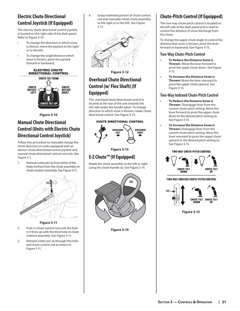
Electric Chute Directional
Control Joystick (If Equipped)The electric chute directional control joystick is located on the right side of the dash panel. Refer to Figure 3-10.
• To change the direction in which snow is thrown, move the joystick to the right or to the left.
• To change the angle/distance which snow is thrown, pivot the joystick forward or backward.
DIRECTIONAL CONTROLELECTRIC CHUTE
CHUTEROTATE
LEFT
CHUTEROTATERIGHT
CHUTE TILT UP
CHUTE TILT DOWN
Figure 3-10
Manual Chute Directional
Control (Units with Electric Chute
Directional Control Joystick)Follow this procedure to manually change the chute direction on units equipped with an electric chute directional control joystick and manual chute directional control rod only. See Figure 3-1.
1. Remove cotter pin (a) from either of the holes furthest from the chute assembly on chute rotation assembly. See Figure 3-11.
(a)
Figure 3-11
2. Push in chute control rod until the hole in it lines up with the third hole in chute rotation assembly. See Figure 3-11.
3. Reinsert cotter pin (a) through this hole and chute control rod as shown in Figure 3-11.
4. Grasp indented portion of chute control rod and manually rotate chute assembly to the right or to the left. See Figure 3-12.
Figure 3-12
Overhead Chute Directional
Control (w/ Flex Shaft) (If
Equipped)The overhead chute directional control is located at the rear of the unit towards the left side under the handle panel. To change direction in which snow is thrown, rotate chute directional control. See Figure 3-13.
CHUTE DIRECTIONAL CONTROL
DISCHARGELEFT
DISCHARGERIGHT
Figure 3-13
E-Z Chute™ (If Equipped)Rotate the chute assembly to the left or right using the chute handle (a). See Figure 3-14.
(a)
Figure 3-14
Chute-Pitch Control (If Equipped)The two-way chute-pitch control is located on the left side of the dash panel and is used to control the distance of snow discharge from the chute.
To change the upper chute angle to control the distance that snow is thrown, pivot the lever forward or backward. See Figure 3-15.
Two-Way Chute-Pitch Control• To Reduce the Distance Snow is
Thrown: Move the lever forward to pivot the upper chute down. See Figure 3-15.
• To Increase the Distance Snow is
Thrown: Move the lever rearward to pivot the upper chute upward. See Figure 3-15.
Two-Way Indexed Chute-Pitch Control• To Reduce the Distance Snow is
Thrown: Disengage lever from the current chute-pitch setting. Move the lever forward to pivot the upper chute down to the desired pitch setting (a). See Figure 3-15.
• To Increase the Distance Snow is
Thrown: Disengage lever from the current chute-pitch setting. Move the lever rearward to pivot the upper chute upward to the desired pitch setting (a). See Figure 3-15.
TWO-WAY CHUTE-PITCH CONTROL
CHUTE TILTDOWN
CHUTE TILTUP
TWO-WAY INDEXED CHUTE-PITCH CONTROL
CHUTE TILTDOWN
CHUTE TILTUP
(a)
Figure 3-15
22 SECTION 3 — CONTROLS & OPERATION
Starting and Stopping the
Engine
WARNING!
Always keep hands and feet clear of moving parts. Do not use a pressurized starting fluid. Vapors are flammable.
Refer to the Engine Operator’s Manual for instructions on starting and stopping the engine.
Pull StartElectric Start
Figure 3-16
To Engage Drive (Drive Control
Lever Units)1. With the throttle control in the Fast
(rabbit) position, move the shift lever into one of the six forward (F) positions or two reverse (R) positions on 6-speed units or in the desired position on the Hydro units. Select a speed appropriate for the snow conditions and a comfortable pace.
2. Squeeze the drive control lever against the handle and the snow thrower will move. Release it and drive motion will stop.
To Engage Augers (Auger Control
Lever Units)To engage the augers and start throwing snow, squeeze the auger control lever against the left handle. Release to stop the augers.
To Engage Drive (Drive Control
Bail Units)1. Move the throttle control into the Fast
(rabbit) position.
2. To engage the drive, squeeze the drive control bail completely against the upper handle to engage the wheels. To stop the forward motion, release the drive control bail.
To Engage Augers (Auger Control
Bail Units)To engage the augers, squeeze the auger control bail completely against the upper handle. To stop the augers, release handle.
To Steer (If Equipped)With the drive control lever engaged, squeeze the right steering trigger control to turn right. Squeeze the left steering trigger control to turn left.
CAUTION
Operate the snow thrower in open areas and at slow speeds until you are familiar with the drive control and comfortable operating the steering controls.
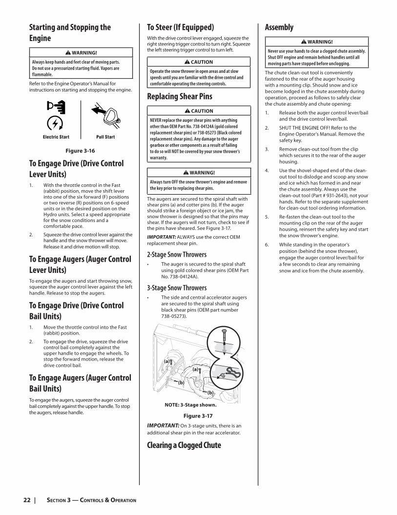
Replacing Shear Pins
CAUTION
NEVER replace the auger shear pins with anything other than OEM Part No. 738-04124A (gold colored replacement shear pins) or 738-05273 (Black colored replacement shear pins). Any damage to the auger gearbox or other components as a result of failing to do so will NOT be covered by your snow thrower’s warranty.
WARNING!
Always turn OFF the snow thrower’s engine and remove the key prior to replacing shear pins.
The augers are secured to the spiral shaft with shear pins (a) and cotter pins (b). If the auger should strike a foreign object or ice jam, the snow thrower is designed so that the pins may shear. If the augers will not turn, check to see if the pins have sheared. See Figure 3-17.
IMPORTANT: ALWAYS use the correct OEM replacement shear pin.
2-Stage Snow Throwers • The auger is secured to the spiral shaft
using gold colored shear pins (OEM Part No. 738-04124A).
3-Stage Snow Throwers • The side and central accelerator augers
are secured to the spiral shaft using black shear pins (OEM part number 738-05273).
NOTE: 3-Stage shown.
(a)
(a)
(b)
(b)
Figure 3-17
IMPORTANT: On 3-stage units, there is an additional shear pin in the rear accelerator.
Clearing a Clogged Chute
Assembly
WARNING!
Never use your hands to clear a clogged chute assembly. Shut OFF engine and remain behind handles until all moving parts have stopped before unclogging.
The chute clean-out tool is conveniently fastened to the rear of the auger housing with a mounting clip. Should snow and ice become lodged in the chute assembly during operation, proceed as follows to safely clear the chute assembly and chute opening:
1. Release both the auger control lever/bail and the drive control lever/bail.
2. SHUT THE ENGINE OFF! Refer to the Engine Operator’s Manual. Remove the safety key.
3. Remove clean-out tool from the clip which secures it to the rear of the auger housing.
4. Use the shovel-shaped end of the clean-out tool to dislodge and scoop any snow and ice which has formed in and near the chute assembly. Always use the clean-out tool (Part # 931-2643), not your hands. Refer to the separate supplement for clean-out tool ordering information.
5. Re-fasten the clean-out tool to the mounting clip on the rear of the auger housing, reinsert the safety key and start the snow thrower’s engine.
6. While standing in the operator’s position (behind the snow thrower), engage the auger control lever/bail for a few seconds to clear any remaining snow and ice from the chute assembly.

23
Product Care 4 WARNING!
Before servicing, repairing or inspecting the snow thrower, disengage the auger control lever. Stop the engine and remove the safety key to prevent unintended starting.
Troubleshooting
Engine Fails to Start1. Choke not in CHOKE position.
• Move choke to CHOKE position. See Engine Operator’s Manual.
2. Spark plug wire disconnected.
• Connect wire to spark plug. See Engine Operator’s Manual.
3. Fuel tank empty or stale fuel.
• Fill tank with clean, fresh fuel. See Engine Operator’s Manual.
4. Engine not primed.
• Prime engine as instructed in Engine Operator’s Manual.
5. Faulty spark plug.
• Clean, adjust gap or replace. See Engine Operator’s Manual.
6. Safety key not in switch.
• Insert safety key fully into switch.
7. Extension cord not connected when using electric start button.
• Connect one end of extension cord to electric starter outlet and other end to a three-prong 120V, grounded, AC outlet. See Engine Operator’s Manual.
Engine Running Erratically/Inconsistent RPM (Hunting or Surging)1. Engine running on CHOKE.
• Move choke lever to RUN position. See Engine Operator’s Manual.
2. Stale fuel.
• Fill tank with clean, fresh fuel. See Engine Operator’s Manual.
3. Water or dirt in fuel system.
• Drain fuel tank. Refill with fresh fuel. See Engine Operator’s Manual.
4. Carburetor out of adjustment.
• Contact an authorized Service Center.
5. Engine over-governed.
• Contact an authorized Service Center.
Engine Overheats1. Engine oil level low.
• Fill engine with proper amount of engine oil.
Excessive Vibration1. Loose parts or damaged auger.
• Stop engine immediately and disconnect the spark plug wire. Check for possible damage. Tighten all nuts and bolts. Repair as needed. If the problem persists, contact an authorized service center.
Unit Fails to Propel Itself1. Drive control cable in need of
adjustment.
• Adjust drive control cable. Refer to Drive Control on page 17.
2. Drive belt loose or damaged.
• Replace drive belt. Contact an authorized Service Center.
3. Friction wheel worn.
• Replace friction wheel. Refer to Service section on page 27.
Unit Fails to Discharge Snow1. Chute assembly clogged.
• Stop engine immediately and disconnect spark plug wire. See Engine Operator’s Manual. Clean chute assembly and inside of auger housing with clean-out tool. Refer to Cleaning a Clogged Chute Assembly on page 22.
2. Foreign object lodged in auger.
• Stop engine immediately and disconnect spark plug wire. See Engine Operator’s Manual. Remove object from auger with clean-out tool. Refer to Cleaning a Clogged Chute Assembly on page 22.
3. Auger control cable in need of adjustment.
• Refer to Auger Control on page 16.
4. Auger belt loose or damaged.
• Refer to Auger Belt Replacement on page 25 and 26.
5. Shear pin(s) sheared.
• Refer to Replacing Shear Pins on page 22.
Chute fails to easily rotate 180 -200 degrees1. Chute assembled incorrectly.
• Unassemble chute control and reassemble as directed in the
Assembly & Set-up section.
Unit Plows Snow Instead of Blowing It1. Low/slow ground speed in wet/slushy
snow 1-3” in depth.
• Increase ground speed and always operate snow thrower engine at FULL throttle. Refer to Cleaning a Clogged Chute Assembly on page 22.
2. Shear pin(s) sheared.
• Refer to Replacing Shear Pins on page 22.
Overhead Chute Crank Does Not Stay Stationary While Throwing Snow1. Insufficient preload applied to chute
control.
• Refer to Chute Assembly on page 25.
Maintenance
EngineRefer to Engine Operator’s Manual.
Tire PressureRefer to Assembly & Set-up section (page 15) for information regarding tire pressure.
Shave Plate & Skid ShoesThe shave plate and skid shoes on the bottom of the snow thrower are subject to wear. They should be checked periodically and replaced when necessary.
NOTE: Deluxe skid shoes (on select models) have two wear edges. When one side wears out, they can be rotated 180° to use the other edge.
24 SECTION 4— PRODUCT CARE
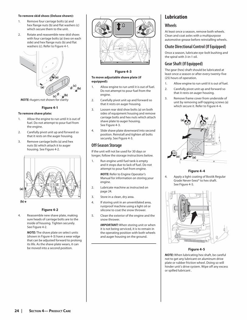
To remove skid shoes (Deluxe shown):
1. Remove four carriage bolts (a) and hex flange nuts (b) and flat washers (c) which secure them to the unit.
2. Rotate and reassemble new skid shoes with four carriage bolts (a) (two on each side) and hex flange nuts (b) and flat washers (c). Refer to Figure 4-1.
NOTE: Augers not shown for clarity
(a)
(a)(c)
(c)
(b)
(b)
Figure 4-1
To remove shave plate:
1. Allow the engine to run until it is out of fuel. Do not attempt to pour fuel from the engine.
2. Carefully pivot unit up and forward so that it rests on the auger housing.
3. Remove carriage bolts (a) and hex nuts (b) which attach it to auger housing. See Figure 4-2.
(a)
(b)
Figure 4-2
4. Reassemble new shave plate, making sure heads of carriage bolts are to the inside of housing. Tighten securely. See Figure 4-2.
NOTE: The shave plate on select units (shown in Figure 4-3) have a wear edge that can be adjusted forward to prolong its life. As the shave plate wears, it can be moved into a second position.
(a)(a)
Figure 4-3
To move adjustable shave plate (if
equipped):
1. Allow engine to run until it is out of fuel. Do not attempt to pour fuel from the engine.
2. Carefully pivot unit up and forward so that it rests on auger housing.
3. Loosen rear skid shoe bolts (a) on both sides of equipment housing and remove carriage bolts and hex nuts which attach shave plate to auger housing. See Figure 4-3.
4. Slide shave plate downward into second position. Reinstall and tighten all bolts securely. See Figure 4-3.
Off-Season StorageIf the unit will not be used for 30 days or longer, follow the storage instructions below.
1. Run engine until fuel tank is empty and it stops due to lack of fuel. Do not attempt to pour fuel from engine.
NOTE: Refer to Engine Operator’s Manual for information on storing your engine.
2. Lubricate machine as instructed on page 24.
3. Store in a clean, dry area.
4. If storing unit in an unventilated area, rustproof machine using a light oil or silicone to coat the snow thrower.
5. Clean the exterior of the engine and the snow thrower.
IMPORTANT: When storing unit or when it is not being serviced, it is to remain in the operating position with both wheels and auger housing on the ground.
Lubrication
WheelsAt least once a season, remove both wheels. Clean and coat axles with a multipurpose automotive grease before reinstalling wheels.
Chute Directional Control (If Equipped)Once a season, lubricate eye-bolt bushing and the spiral with 3-in-1 oil.
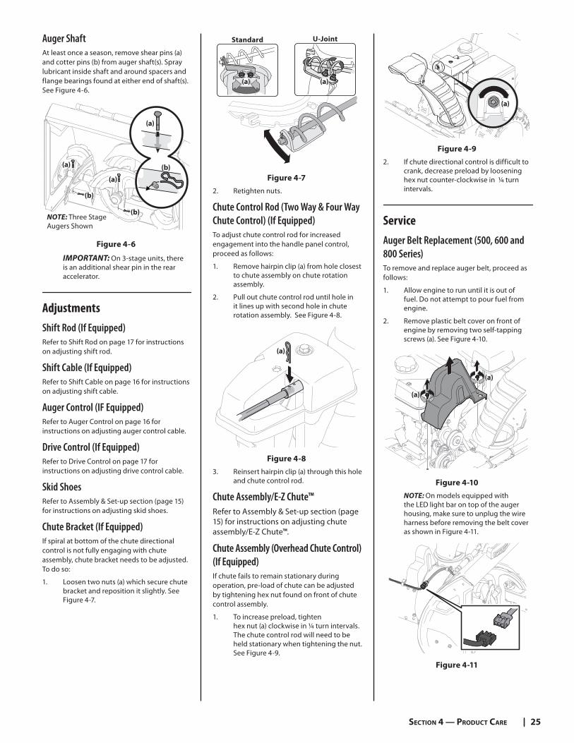
Gear Shaft (If Equipped)The gear (hex) shaft should be lubricated at least once a season or after every twenty-five (25) hours of operation.
1. Allow engine to run until it is out of fuel.
2. Carefully pivot unit up and forward so that it rests on auger housing.
3. Remove frame cover from underside of unit by removing self-tapping screws (a) which secure it. Refer to Figure 4-4.
(a) (a)
(a)(a)
Figure 4-4
4. Apply a light coating of Bostik Regular Grade Never-Seez® to hex shaft. See Figure 4-5.
Figure 4-5
NOTE: When lubricating hex shaft, be careful not to get any lubricant on aluminum drive plate or rubber friction wheel. Doing so will hinder unit’s drive system. Wipe off any excess or spilled lubricant .
25SECTION 4 — PRODUCT CARE
Auger ShaftAt least once a season, remove shear pins (a) and cotter pins (b) from auger shaft(s). Spray lubricant inside shaft and around spacers and flange bearings found at either end of shaft(s). See Figure 4-6.
(a)
(a)
(b)
(b)NOTE: Three Stage Augers Shown
(a)
(b)
Figure 4-6
IMPORTANT: On 3-stage units, there is an additional shear pin in the rear accelerator.
Adjustments
Shift Rod (If Equipped)Refer to Shift Rod on page 17 for instructions on adjusting shift rod.
Shift Cable (If Equipped)Refer to Shift Cable on page 16 for instructions on adjusting shift cable.
Auger Control (IF Equipped)Refer to Auger Control on page 16 for instructions on adjusting auger control cable.
Drive Control (If Equipped)Refer to Drive Control on page 17 for instructions on adjusting drive control cable.
Skid ShoesRefer to Assembly & Set-up section (page 15) for instructions on adjusting skid shoes.
Chute Bracket (If Equipped)If spiral at bottom of the chute directional control is not fully engaging with chute assembly, chute bracket needs to be adjusted. To do so:
1. Loosen two nuts (a) which secure chute bracket and reposition it slightly. See Figure 4-7.
Standard U-Joint
(a) (a)
Figure 4-7
2. Retighten nuts.
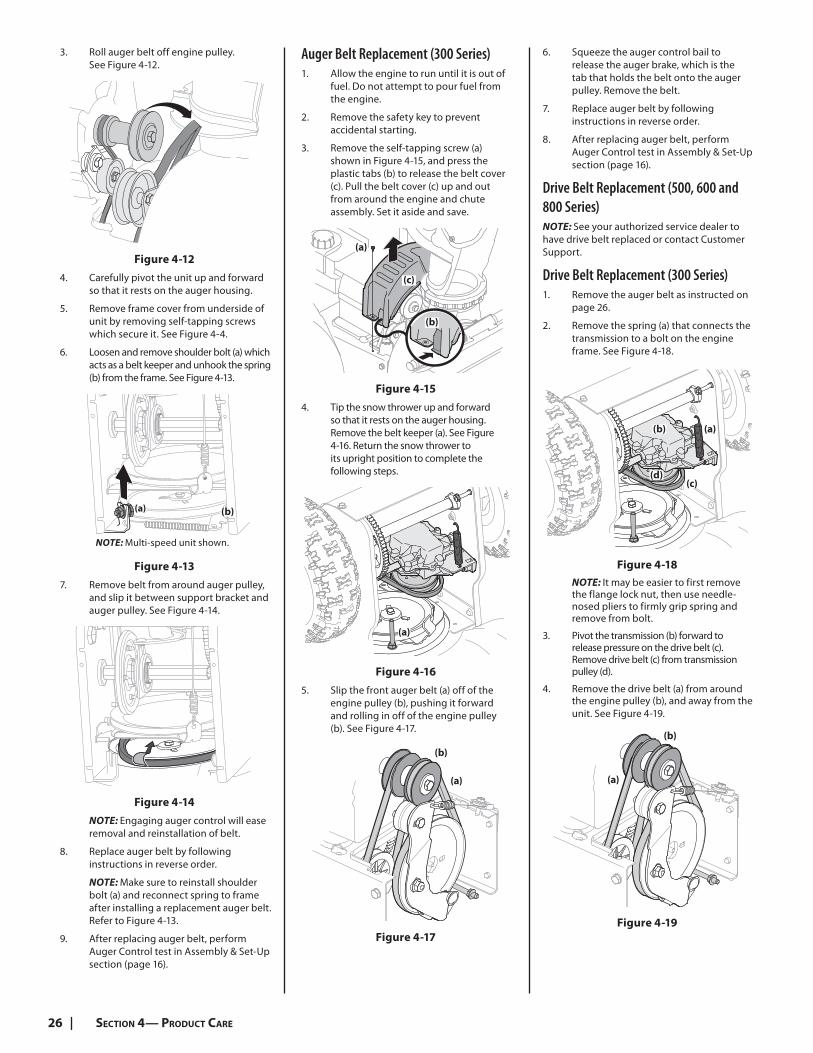
Chute Control Rod (Two Way & Four Way Chute Control) (If Equipped)To adjust chute control rod for increased engagement into the handle panel control, proceed as follows:
1. Remove hairpin clip (a) from hole closest to chute assembly on chute rotation assembly.
2. Pull out chute control rod until hole in it lines up with second hole in chute rotation assembly. See Figure 4-8.
(a)
Figure 4-8
3. Reinsert hairpin clip (a) through this hole and chute control rod.
Chute Assembly/E-Z Chute™Refer to Assembly & Set-up section (page 15) for instructions on adjusting chute assembly/E-Z Chute™.
Chute Assembly (Overhead Chute Control) (If Equipped)If chute fails to remain stationary during operation, pre-load of chute can be adjusted by tightening hex nut found on front of chute control assembly.
1. To increase preload, tighten hex nut (a) clockwise in ¼ turn intervals. The chute control rod will need to be held stationary when tightening the nut. See Figure 4-9.
(a)
Figure 4-9
2. If chute directional control is difficult to crank, decrease preload by loosening hex nut counter-clockwise in ¼ turn intervals.
Service
Auger Belt Replacement (500, 600 and 800 Series)To remove and replace auger belt, proceed as follows:
1. Allow engine to run until it is out of fuel. Do not attempt to pour fuel from engine.
2. Remove plastic belt cover on front of engine by removing two self-tapping screws (a). See Figure 4-10.
(a)
(a)
Figure 4-10
NOTE: On models equipped with the LED light bar on top of the auger housing, make sure to unplug the wire harness before removing the belt cover as shown in Figure 4-11.
Figure 4-11
26 SECTION 4— PRODUCT CARE
3. Roll auger belt off engine pulley. See Figure 4-12.
Figure 4-12
4. Carefully pivot the unit up and forward so that it rests on the auger housing.
5. Remove frame cover from underside of unit by removing self-tapping screws which secure it. See Figure 4-4.
6. Loosen and remove shoulder bolt (a) which acts as a belt keeper and unhook the spring (b) from the frame. See Figure 4-13.
NOTE: Multi-speed unit shown.
(a) (b)
Figure 4-13
7. Remove belt from around auger pulley, and slip it between support bracket and auger pulley. See Figure 4-14.
Figure 4-14
NOTE: Engaging auger control will ease removal and reinstallation of belt.
8. Replace auger belt by following instructions in reverse order.
NOTE: Make sure to reinstall shoulder bolt (a) and reconnect spring to frame after installing a replacement auger belt. Refer to Figure 4-13.
9. After replacing auger belt, perform Auger Control test in Assembly & Set-Up section (page 16).
Auger Belt Replacement (300 Series)1. Allow the engine to run until it is out of
fuel. Do not attempt to pour fuel from the engine.
2. Remove the safety key to prevent accidental starting.
3. Remove the self-tapping screw (a) shown in Figure 4-15, and press the plastic tabs (b) to release the belt cover (c). Pull the belt cover (c) up and out from around the engine and chute assembly. Set it aside and save.
(a)
(c)
(b)
Figure 4-15
4. Tip the snow thrower up and forward so that it rests on the auger housing. Remove the belt keeper (a). See Figure 4-16. Return the snow thrower to its upright position to complete the following steps.
(a)
Figure 4-16
5. Slip the front auger belt (a) off of the engine pulley (b), pushing it forward and rolling in off of the engine pulley (b). See Figure 4-17.
(a)
(b)
Figure 4-17
6. Squeeze the auger control bail to release the auger brake, which is the tab that holds the belt onto the auger pulley. Remove the belt.
7. Replace auger belt by following instructions in reverse order.
8. After replacing auger belt, perform Auger Control test in Assembly & Set-Up section (page 16).
Drive Belt Replacement (500, 600 and 800 Series)NOTE: See your authorized service dealer to have drive belt replaced or contact Customer Support.
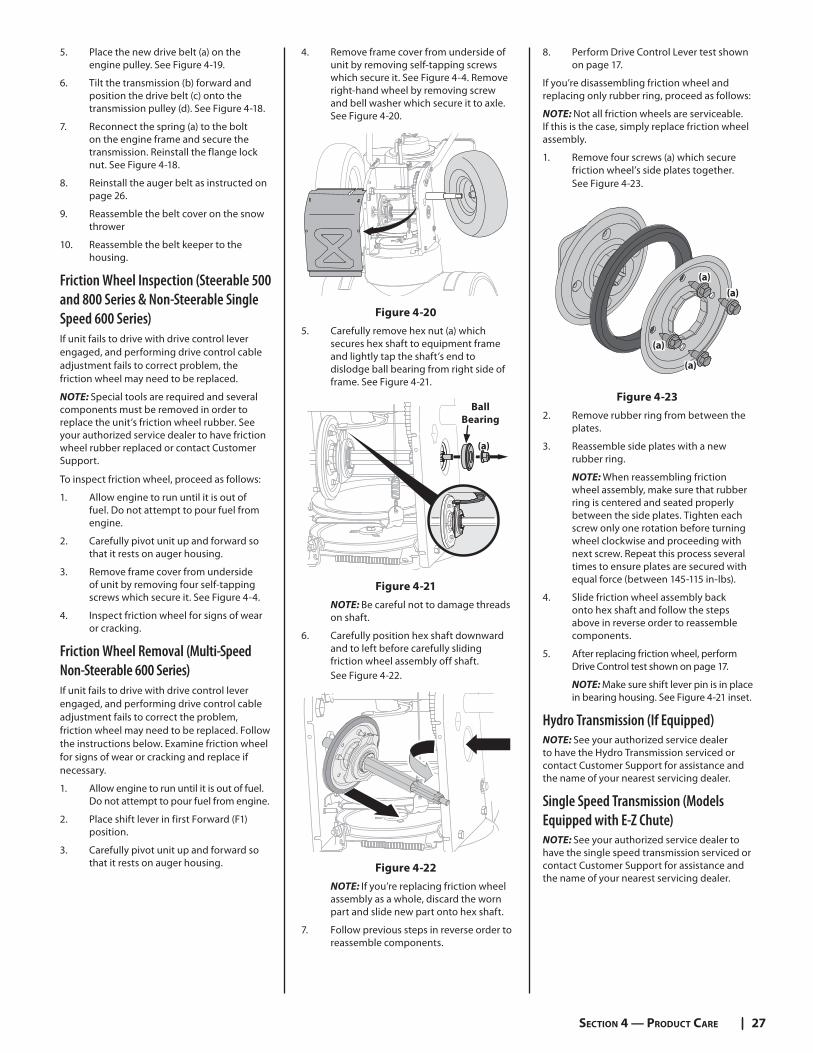
Drive Belt Replacement (300 Series)1. Remove the auger belt as instructed on
page 26.
2. Remove the spring (a) that connects the transmission to a bolt on the engine frame. See Figure 4-18.
(a)
(c)
(b)
(d)
Figure 4-18
NOTE: It may be easier to first remove the flange lock nut, then use needle-nosed pliers to firmly grip spring and remove from bolt.
3. Pivot the transmission (b) forward to release pressure on the drive belt (c). Remove drive belt (c) from transmission pulley (d).
4. Remove the drive belt (a) from around the engine pulley (b), and away from the unit. See Figure 4-19.
(a)
(b)
Figure 4-19
27SECTION 4 — PRODUCT CARE
5. Place the new drive belt (a) on the engine pulley. See Figure 4-19.
6. Tilt the transmission (b) forward and position the drive belt (c) onto the transmission pulley (d). See Figure 4-18.
7. Reconnect the spring (a) to the bolt on the engine frame and secure the transmission. Reinstall the flange lock nut. See Figure 4-18.
8. Reinstall the auger belt as instructed on page 26.
9. Reassemble the belt cover on the snow thrower
10. Reassemble the belt keeper to the housing.
Friction Wheel Inspection (Steerable 500 and 800 Series & Non-Steerable Single Speed 600 Series)If unit fails to drive with drive control lever engaged, and performing drive control cable adjustment fails to correct problem, the friction wheel may need to be replaced.
NOTE: Special tools are required and several components must be removed in order to replace the unit’s friction wheel rubber. See your authorized service dealer to have friction wheel rubber replaced or contact Customer Support.
To inspect friction wheel, proceed as follows:
1. Allow engine to run until it is out of fuel. Do not attempt to pour fuel from engine.
2. Carefully pivot unit up and forward so that it rests on auger housing.
3. Remove frame cover from underside of unit by removing four self-tapping screws which secure it. See Figure 4-4.
4. Inspect friction wheel for signs of wear or cracking.
Friction Wheel Removal (Multi-Speed Non-Steerable 600 Series)If unit fails to drive with drive control lever engaged, and performing drive control cable adjustment fails to correct the problem, friction wheel may need to be replaced. Follow the instructions below. Examine friction wheel for signs of wear or cracking and replace if necessary.
1. Allow engine to run until it is out of fuel. Do not attempt to pour fuel from engine.
2. Place shift lever in first Forward (F1) position.
3. Carefully pivot unit up and forward so that it rests on auger housing.
4. Remove frame cover from underside of unit by removing self-tapping screws which secure it. See Figure 4-4. Remove right-hand wheel by removing screw and bell washer which secure it to axle. See Figure 4-20.
Figure 4-20
5. Carefully remove hex nut (a) which secures hex shaft to equipment frame and lightly tap the shaft’s end to dislodge ball bearing from right side of frame. See Figure 4-21.
(a)
Ball
Bearing
Figure 4-21
NOTE: Be careful not to damage threads on shaft.
6. Carefully position hex shaft downward and to left before carefully sliding friction wheel assembly off shaft. See Figure 4-22.
Figure 4-22
NOTE: If you’re replacing friction wheel assembly as a whole, discard the worn part and slide new part onto hex shaft.
7. Follow previous steps in reverse order to reassemble components.
8. Perform Drive Control Lever test shown on page 17.
If you’re disassembling friction wheel and replacing only rubber ring, proceed as follows:
NOTE: Not all friction wheels are serviceable. If this is the case, simply replace friction wheel assembly.
1. Remove four screws (a) which secure friction wheel’s side plates together. See Figure 4-23.
(a)
(a)
(a)
(a)
Figure 4-23
2. Remove rubber ring from between the plates.
3. Reassemble side plates with a new rubber ring.
NOTE: When reassembling friction wheel assembly, make sure that rubber ring is centered and seated properly between the side plates. Tighten each screw only one rotation before turning wheel clockwise and proceeding with next screw. Repeat this process several times to ensure plates are secured with equal force (between 145-115 in-lbs).
4. Slide friction wheel assembly back onto hex shaft and follow the steps above in reverse order to reassemble components.
5. After replacing friction wheel, perform Drive Control test shown on page 17.
NOTE: Make sure shift lever pin is in place in bearing housing. See Figure 4-21 inset.
Hydro Transmission (If Equipped)NOTE: See your authorized service dealer to have the Hydro Transmission serviced or contact Customer Support for assistance and the name of your nearest servicing dealer.
Single Speed Transmission (Models Equipped with E-Z Chute)NOTE: See your authorized service dealer to have the single speed transmission serviced or contact Customer Support for assistance and the name of your nearest servicing dealer.

Notes
28