Embed Size (px)
Citation preview

Page 1 of 1 SUBCONTRACTOR’S SUBMITTAL TRANSMITTAL
PROJECT NO.
TRANSMITTAL NO. 14B
DATE 7/17/17
FROM CONTRACTOR HUMPHREY MECHANICAL, INC.
PROJECT TITLE AND LOCATION
PENDERLEA K-8 SCHOOL WILLARD, NC TO
METCON CONTRACTOR USE ONLY REVEIWER USE ONLY
*List only one specification division per form.
List only one of the following categories on each transmittal form and indicate which is being submitted.
**ACTION CODES
A-Approved D-Disapproved AN-Approved as noted RA-Receipt acknowledged C-Comments R-Resubmit
Contractor Approved Approved
Deviation/Substitution For Approval
ITEM NO
PROJ. SPEC. SECT. & PARA. and/or PROJ.
DWG. NO.
ITEM IDENTIFICATION (Type, size, model no., Mfg. Name, dwg. or
brochure number)
NO. OF COPIES
ACTION CODES
***
REVIEWER’S INITIALS
CODE AND DATE
1 23 73 13 CENTRAL STATION AIR HANDLING UNTS
AIR HANDLERS
REVISED-AHU6
CONTRACTOR’S COMMENTS
See attached resolution letter
COPY OF TRANSMITTAL AND SUBMITTALS TO ROICC
CONTRACTOR REPRESENTATIVE (Signature)
Lisa Neagle DATE RECEIVED BY REVIEWER
FROM (Reviewer) TO
REVIEWER’S COMMENTS
COPIES TO:
DATE SIGNATURE

SUBMITTAL # 14 23 73 13-001 AIR HANDLER UNITS
DISPOSITION / RESOLUTION TO SUBMITTAL COMMENTS
Comment # Comment Disposition / Resolution
1 Deletion of piping vestibules on all units is acceptable, provide credit to owner for change
There is no credit for deletion of vestibules to the AHUs as we did not include vetibules on them in the first place since they were indoor units and do not require vestibules and it does not make sense to be specifying vestibules for indoor units where the piping is not going to be connected to the units from the bottom of the unit. Piping work is not deleted as it will be worked in the field to connect to the unit. Besides, assuming that piping was to feed the units from below and into a vestibule, a credit for that vestibule will be offset by the added longer piping runs and the added insulation.
2
Only provide CHW UV coil protection on AHUs 1,2,3,4. Provide shorter CHW coil and access sections on ahu-5 as part of this change. Provide credit to owner for deletion of UV lights on AHU’s 5,6,7,8.
We have revised the AHUs submittals and incorporated all comments per the attached submittal. Credit for the deletion of the UV lights on 3 AHUs heating coils from the manufacturer is $1500 ($500 per coil)
3
Provide AHU-6 as attached (13 pages directly following this cover and prior to the METCON transmittal sheet) in lieu of AHU-6 submitted. Adjust unit locations for increased unit sizing to fit on platform with contractor coordination drawings. Coordinate water flow changes with flow control device rep and tab contractor.
Revised submittals for the AHIUs is attached that incorporates all changes requested.
4 TRAQ dampers in mixing boxes are not approved, provide standard mixing boxes with filter rack assembly
We can provide that but does this mean that the AFS are not needed? If so we can provide credit for these noting that we complied with the specs and drawings requirements regarding these TRAQ dampers and if air measuring flow stations will be required then there is an added cost to it.
5
Coordinate motors with operation over 60HZ with VFD manufacturer and tab contractor. Trane to confirm warranties still valid for operating at greater than 60 HZ.
The manufacturer has confirmed that the AHU motors can be run over 60 HZ. See attached white paper published by Trane regarding operating motors over 60 HZ. We confirm also that the VFDs can operate even at higher frequencies than what the motors can run.

White Paper
Understanding Flexible Motor Speed Selection for
Direct-Drive Plenum Fans
Executive Summary
Direct-drive plenum (DDP) fans, particularly when used in arrays, are a popular, efficient, and versatile option for air handling units in many applications. The Flexible Motor Speed selection method uses a variable frequency drive (VFD) to vary the fan speed - above or below the motor nominal speed - to achieve the desired fan operating point. Operating near or above motor nominal speed will ensure that efficiency, acoustics, and turndown are optimized.
Problem
When using DDP fans, it's rare that the speed needed by the fan matches the nominal speed of an available motor. Unlike belt driven fans, there is no drive kit to allow matching of the motor speed to the desired fan speed. The VFD can be used to set the fan speed to something other than motor nominal, but the motor must be selected correctly to ensure proper performance and avoid any issues.
Solution
VFDs are commonly used to vary the speed of fans between a minimum speed and the motor nominal speed (typically 20Hz - 60Hz). A VFD can also be used to set the base speed of a direct-drive fan similar to how a drive kit is applied with a belt driven fan.
If the fan speed happens to match the motor nominal speed, then we can treat our system just as if the fan were belt-driven. However, in the much more common case where the fan speed does not match an available motor nominal speed, the VFD can allow us to easily dial in the fan operation.
We will consider two approaches using this VFD plus motor combination to achieve our needed fan speed, one of which has many advantages over the other:
CLCH-PRB061A-ENSeptember 2016

2 CLCH-PRB061A-EN
• Under-speed: Picking a motor with a nominal speed above the selected fan speed and using the VFD to limit operation below motor nominal speed.
• Over-speed: Picking a motor with a nominal speed below the selected fan speed and using the VFD to allow operation above motor nominal speed.
Solution Details
To understand motor application at non-nominal speeds, it's important to understand the fundamentals of VFD and motor operation as well as fan behavior at different speeds. We'll begin with a brief review of these topics.
Fundamentals
Induction Motor Basics
We will limit this discussion to NEMA Design B 3-phase motors, which are common in HVAC fan applications. A Design B motor has favorable characteristics for fan use since it has a maximum 5 percent slip (more typically 1-3 percent), reasonable starting current, high locked rotor torque, and break down torque suitable for general applications. A generic torque versus speed curve is shown in Figure 1 for a Design B motor at a constant input voltage and frequency.
There are a few important parameters necessary for discussing induction motor operation:
• Locked Rotor Torque: The locked rotor torque is the starting torque the motor is able to produce from a full stop.
• Breakdown Torque: The breakdown torque is the maximum torque the motor can produce without stalling.
• Synchronous Speed: The motor synchronous speed is the theoretical speed of the motor at no load and with no internal losses.
• Nominal Speed: The nominal speed is the rated speed of the motor at rated input voltage and frequency.
• Slip: Slip is the difference between the synchronous and nominal speeds. The motor's rated slip is a good general indicator of efficiency, but slip will vary during normal operation as the load, voltage, and frequency change.
These parameters are all a function of the motor design, are determined through testing, and can not be changed when running at rated conditions.
The construction of all motors in the US is dictated by the NEMA MG-1 standard. The standard covers the construction, testing, and minimum performance of the motors.
Three phase motors can only be constructed with a finite number of magnetic poles. Because the poles must be in matched pairs, the number of poles must be an even number with a minimum of two. The number of these poles dictates the synchronous speed of the motor through the relationship:
The synchronous speed of a motor is thus inversely proportional to its number of poles. For example:
• 2-pole motor rated at 60 Hz would have a synchronous speed of 3600 RPM
• 4-pole motor rated at 60 Hz would have a synchronous speed of 1800 RPM
• 6-pole motor rated at 60 Hz would have a synchronous speed of 1200 RPM, and so on.
Figure 1. Idealized torque vs. speed curve for a NEMA
Design B motor with constant input voltage
and frequency
Equation 1
-ns = (120 * f) / p
-where,
-ns is the motor synchronous speed in RPM
-f is the frequency of the motor input voltage in Hz
-p is the number of motor poles
Figure 2. Cut-away sketch of Design B TEFC motor

CLCH-PRB061A-EN 3
Fan Basics
Direct-drive plenum fans have a number of advantages over more traditional fan types. They are efficient, quiet, and require very little maintenance. They can also be used in an array for redundancy applications.
A belt-driven fan uses a drive kit to translate the motor speed, typically 1800 RPM, to the fan speed needed to meet the duty point. Because a direct-drive fan doesn’t have a drive kit, an alternate approach must be used. When discussing direct-drive selection methods, there are two common approaches: synchronous motor speed and flexible motor speed.
Synchronous Motor Speed
The synchronous motor speed selection method simply operates the fan at the motor synchronous speed with 1200, 1800, and 3600 rpm being typical. To tune the fan for a specific operating point, the fan width and diameter are adjusted. With this approach, capacity adjustments to account for a missed system, etc. are not easily achieved. Also, this selection method will result in higher speeds which will increase the sound levels.
Flexible Motor Speed
The more common approach is known as the flexible motor speed selection method. This approach utilizes a VFD as a drive kit to operate a motor below—or above—motor synchronous speed. The VFD can also be used to make easy capacity adjustments if a system is missed or for future operation.
Fan selection begins with an airflow and a pressure needed to overcome that airflow. Outputs of fan selection include the fan speed and power requirements. When selecting a motor using the flexible motor speed method, the fan will dictate the motor speed and power requirements.
For a given system, fan performance at speeds different from design can be predicted using fan affinity laws. In particular, the shaft power requirements change with the cube of shaft speed. In other words: if the fan speed is increased by 10 percent, the fan will require 33 percent more power to operate. As we discuss motors operating above their synchronous speed, it’s important to distinguish the selection of a fan at a speed matching 60Hz and the selection of a fan at a speed above 60Hz.
Motor Operation on a VFD
A VFD, as the name suggests, controls motor speed by varying the frequency of the motor's input voltage. As shown in Equation 1, the synchronous speed of the motor changes proportionally with frequency. This results in a very reliable speed control method.
As the input frequency to the motor is reduced, the input voltage must be varied as well to maintain stable motor temperature and torque. The motor torque is directly
proportional to the magnetizing current in the stator windings. The magnetizing current is defined by:
The magnetizing current is thus proportional to voltage and inversely proportional to frequency. As the magnetizing current is increased, the iron core losses in the motor increase due to the electrical resistance of the iron so—to minimize losses and prevent over heating of the iron core—the magnetizing current must be reduced by lowering the voltage as the frequency is reduced.
The reduction in voltage as frequency/speed decreases allows a VFD operated motor to maintain a constant level of torque below the motor rated, or base, frequency (60 Hz for example). Constant torque with decreasing speed gives an approximately linear reduction in horsepower as the motor slows. To deliver full torque at the motor rated frequency, the VFD must output full voltage. For frequencies above the base frequency, the VFD is already at maximum voltage so voltage must be held constant as frequency increases. This causes the torque to decrease as frequency, and thus speed, increases in this region of operation which gives a near constant horsepower above base frequency Equation 3 shows this torque – horsepower relationship. Refer to Figure 4 for a representation of the torque and horsepower over the full speed range.
Equation 2
-Im = (V/(2 * π * f * L))
where
Im is the magnetizing current
f is the operating frequency
L is the motor inductance
V is the operating voltage
Figure 3. Motor torque curves shifted as VFD
frequency changes

4 CLCH-PRB061A-EN
Theoretically, as the motor frequency increases above base frequency, motor torque will drop linearly as shown in Equation 2. As the rotor spins faster, there are additional windage and friction losses that must be accounted for. To ensure these losses are covered, and to give an additional margin of safety to the design, the torque is assumed to decrease as the square of the speed when selecting a motor in this region.
The available horsepower will, theoretically, remain constant in this region over base frequency. This is true to at least 150 percent of base frequency for a NEMA Design B motor. Due to the decreasing torque, the available motor horsepower will begin to decrease slightly between 150 and 200 percent of base frequency depending on the characteristics of the motor.
Motor Operation Below Nominal Speed
The first approach to selecting a motor and VFD for a DDP fan, sometimes called under-speed, is to select a motor with a nominal speed above the fan design speed and use the VFD to limit the motor speed to the fan design speed. This slows the motor to below the base frequency and operates in the constant torque / reduced HP region.
The under-speed concept is often easily accepted, because it is so similar to how a VFD works with other fan types -
by slowing down the motor from nominal speed. However, there are several negatives to this approach:
• The design speed is below the motor nominal speed. If the VFD is not setup properly to limit the speed, the fan could produce higher than design airflow and there could be nuisance overcurrent tripping of the VFD as well as the possibility of over pressurizing the system.
• The motor is being selected in the region of decreased horsepower. This requires that the motor be derated from its nameplate horsepower by the ratio of fan speed to motor nominal speed. For example, a 10 hp 1777 rpm motor on a fan selected at 1400 rpm would only have (10 * 1400 / 1777) = 7.9 hp available at the reduced speed. The motor would thus need to be up sized to 15 hp if the fan required more than 7.9 brake horsepower.
• One of the biggest factors in the efficiency of a given motor is the loading. A motor is designed to provide its highest efficiency at, or near, full load and begins to drop quickly below approximately 50 percent load. In our previous example, the motor efficiency at the fan speed is below the motor full load efficiency because of the derating. Figure 5 shows the efficiency curve of a typical 10 hp 1800 rpm motor compared to the percent of full load. If we assume the bhp of 8 from our example fan, which would require a 15 hp motor, the motor efficiency will be limited from 92 percent down to 90 percent at the fan speed.
• With maximum motor speed limited below nominal, the available fan turn down can be greatly reduced. We'll assume a minimum acceptable motor speed of 20 Hz. Referring to our last example again, the 1777 rpm motor has a minimum speed of (1777 * 20 / 60) 592 rpm. A fan selected at nominal speed would have a 3:1,
Equation 3
T = 5252 * HP / RPM
where
T is motor torque
HP is motor horsepower
RPM is motor speed
Figure 4. Idealized torque and horsepower of VFD plus
motor combination vs frequency/speed
Figure 5. Typical induction motor efficiency curve

CLCH-PRB061A-EN 5
or 33 percent, turn down ratio (592/1777) while the under-speed selection allows for only a 2.3:1, or 42 percent, turn down ratio (592 / 1400). This reduced turn down capability could cause control issues at minimum airflow when the fan may still be producing more than the desired airflow at minimum fan speed.
With the above in mind, care must be taken with this approach to ensure that the motor is derated properly and that the VFD is properly configured to avoid serious problems.
As can be seen, an undersped motor has many disadvantages. The most visible potential advantage would be the possibility of a slightly more efficient motor when the fan speed is close to the motor nominal speed of the next motor. For example, an undersped 3600 rpm motor could be more efficient than an oversped 1800 rpm motor at a fan speed of 3300 rpm. This is because the 1800 rpm motor may have been upsized to handle the torque necessary to operate at this speed.
Motor Operation Above Nominal Speed
The second approach to selecting a motor and VFD for a DDP fan, sometimes called over-speed, is to select a motor with a nominal speed less than the fan design speed and use a VFD to increase the maximum motor speed to match the fan design speed. In general, this second approach is far superior to the first, but it has possible issues that must be accounted for.
While operation above nominal speed may seem like a new trend, the NEMA MG-1 standard has required certain motors be designed for this operation for many years. These would be general purpose motors, intended for use with VFDs, directly coupled to a load (e.g., direct-drive).
Figure 6 contains excerpts from the standard. Section 30.2.2.2.4 discusses proper motor selection when applying a motor above nominal speed, which we will summarize and clarify below. Table 30-1 lists the minimum operating speeds the motors must be capable of running at. Note how motors 30 hp and below—rated at 1200, 1800, and 3600 rpm—must be designed up to one and one-half times the motor base speed or 90 Hz. Motors 20 hp and below—rated at 1800 rpm—must be designed up to two times the motor base speed or 120 Hz.
Figure 6. Excerpts from the NEMA MG-1 Standard

6 CLCH-PRB061A-EN
There are several advantages to this approach which result in superior performance:
• A fan design speed above motor nominal speed gives an improved turn down ratio. Considering the 10 hp 1777 rpm motor from earlier, this time with a fan speed of 2700 rpm, the turn down ratio will improve to 4.6:1, or 21 percent, (592 / 2700).
• Since the fan speed is above the motor nominal speed, there will be no over current trips and there is no danger of over pressurizing the system if the VFD is not setup properly. On the other hand, the fan will not meet design airflow.
• The fan design speed is selected in the region of constant horsepower so there is no motor derate required; although torque above 90 Hz must be evaluated.
• Motor efficiency at fan design speed will be at, or near, the motor nominal efficiency (the motor does not have to be derated). That is, efficiency will be near that of full load.
While there are a number of advantages, the disadvantages are few:
• Slight reduction in bearing life as a result of increased speed. Compared to a belt-driven fan however, the bearing life, even when oversped, is much better for a direct-driven fan.
• Slight reduction in motor efficiency as a result of the increased losses that are a function of speed (windage and friction primarily). However, since derating of the motor is not necessary, the efficiency advantages of over speed far outweigh under speed.
When selecting a motor above nominal speed, ensure that the motor is capable of the required design speed. Table 30-1 in Figure 6 is a good reference to verify the motor design speeds. This also ensures the motor bearings are designed for these higher speeds.
If the fan speed will not exceed 90 Hz, then the motor can be sized using the nameplate rated horsepower—there is no derate of horsepower required in this range. The only requirement is that the brake horsepower at the fan speed must be less than the nameplated motor horsepower (optimized motor selections being the exception).
As an example let's consider a DDP fan selected at 2400 rpm and 9.0 bhp. Using an 1800 rpm 10 hp motor, we first confirm that the motor will operate at 90 Hz, or less, by scaling the base frequency up by the ratio of speed increase: (2400 / 1800 * 60) = 80 Hz. In this case, the fan brake horsepower is less than the motor rated horsepower and the motor speed will be less than 90 Hz so this is a good selection.
If the fan speed will be between 90 Hz and 120 Hz, then the torque capabilities of the motor will need to be evaluated. The available motor torque decreases, conservatively, with the square of the speed increase above nominal. In this range, the torque reduction may begin to affect the
motor's available horsepower. Rather than finding the available motor torque at the fan speed directly, Equation 4 can be used to find the maximum fan speed (in Hz, based on 60 Hz nominal speed) at which a given motor can stably operate based on the motor parameters and brake horsepower required.
Note: A 10 percent voltage loss below motor rated voltage is assumed.
As an example let's consider a DDP fan selected at 3000 rpm and 12.5 bhp. We must first find the required motor speed and confirm that the motor is capable of operation there. An 1800 rpm motor would need to be ran at (3000 / 1800 * 60) = 100 Hz for this selection. Using Table 30-1 in Figure 6, both the 15 and 20 hp 1800 rpm motors are capable of operation up to 120 Hz. The break down torque must be obtained from the motor manufacturer for the motor to be evaluated.
In this example, we will assume a 225 percent break down torque for both the 15 and 20 hp motors. Using Equation 4, we find that the 15 hp motor is only able to support (15 / 12.5 * 0.9 * 60 * SQRT(225 / 100)) = 97.2 Hz at our required brake horsepower. We evaluate the 20 hp motor to find that it is able to support up to (20 / 12.5 * 0.9 * 60 * SQRT(225 / 100)) = 129.6 Hz at our required brake horsepower, which is more than enough for this selection. For this application, even though it had plenty of horsepower, the 15 hp motor did not have enough torque available so the next larger motor must be used.
It’s important to note that operation above nominal speed is a design method, not a band-aid. As we’ve seen, a motor can be easily oversped and selected based on the bhp at the fan speed above 60Hz. If the motor is instead sized for the brake horsepower assuming the fan/motor is running at 60Hz, the motor will quickly over current considering how the fan’s power requirements will increase with the cube of speed based on fan affinity laws.
TOPSS Selection Software
In the TOPSS selection software, there are multiple options to address motor speed selection:
• Best available
• At or above synchronous speed
• Below synchronous speed
Equation 4
Smax = HP / BHP * 0.9 * 60 * SQRT(BDT / 100)
where,
Smax is the maximum fan speed in Hz, based on a 60 Hz nominal speed
HP is the motor nameplate horsepower
BHP is the required fan brake horsepower
BDT is the motor break down torque in percent

Trane optimizes the performance of homes and buildings around the world. A business of Ingersoll Rand, the leader increating and sustaining safe, comfortable and energy efficient environments, Trane offers a broad portfolio of advancedcontrols and HVAC systems, comprehensive building services, and parts. For more information, visit www.Trane.com.
Trane has a policy of continuous product and product data improvement and reserves the right to change design and specifications without notice.
We are committed to using environmentally
conscious print practices that reduce waste.
The “Best available” option will chose “Below synchronous speed” if close to the motor synchronous speed (e.g., a fan speed of 1700 vs. a motor synchronous speed of 1800) and “At or above synchronous speed” otherwise. Also, “Best available” will try to minimize the use of unregulated, 8-pole (900 rpm) motors.
Action
The flexible motor speed selection method is a superior way to operate a direct-drive fan in the most efficient manner possible. Share this document with your customers that are uncomfortable with overspeeding a motor beyond 60Hz; noting the differences between a band aid and a selection method in particular.
Figure 7. Exploded view of Design B TEFC motor
© 2016 Trane All rights reserved
CLCH-PRB061A-EN 30 Sep 2016
(NEW)
Prepared For: Optima Engineering
Date: June 21, 2017 Customer P.O. Number: Customer Project Number:
Sold To: Humphrey Mechanical 2421 N. Marine Boulevard JACKSONVILLE, NC 28546
Job Number: Job Name: Penderlea K-8
Trane U.S. Inc. is pleased to provide the enclosed submittal for your review and approval. Product Summary
Qty Product 8 Performance Climate Changer – AHU-1 – AHU-8 Submittal Notes:
AHU-1 – AHU-8 motor voltage is 460/60/3 phase
AHU-1, AHU-2, AHU-5, AHU-8 have right hand doors, coil connections, and drain pan connections (air in face)
AHU-3, AHU-4, AHU-6, AHU-7 have left hand doors, coil connections, and drain pan connections (air in face)
AHU-1, 2, 3, 4, 7 have dual motors
All AHU’s provide with 3 Total Sets of filters
Trane is requesting permission to exclude piping vestibulles (Accessory R) since all of the AHU’s are indoor units.
AHU-6 show a scheduled size 8 air handler. With a CFM of 5,600 a size 12 is necessary to keep the face velocity on the coils in a good operating range. Please confirm a size 12 will fit in the space and the 5,600 CFM is correct.
Revision Notes:
Piping vestibule credit break down form MC
UV Lights were removed from AHU-5, 6, 7, and 8. MC to provide credit break down.
AHU-6 selected per returned submittal from engineer.
TRAQ dampers in mixing boxes removed. Ebrtron duct mounted air flow stations to be provided
Trane confrims warranties still valid for operating at greater than 60Hz
AHU-7 adjusted from 1.5” SP to 1.25” SP as scheduled
Pre-Heat coils reselected with EAT of 20F
Kevin Fischer Trane 6736A Netherlands Dr. Wilmington, NC 28405 Phone: (910) 792-0339 Fax: (910) 792-1466
The attached information describes the equipment we propose to furnish for this project, and is submitted for your approval. Product performance and submittal data is valid for a period of 6 months from the date of submittal generation. If six months or more has elapsed between submittal generation and equipment release, the product performance and submittal data will need to be verified. It is the customer’s responsibility to obtain such verification.
Revised Submittal
J:\JOBS\159\22796\2\Penderlea K-8 AHU Submittal R2.doc

Table Of Contents
Product Summary ........................................................................................................................... 1
Performance Climate Changer (Items A1 - A8) ............................................................................ 3 Tag Data .................................................................................................................................................. 3 Product Data ............................................................................................................................................ 3 Performance Data .................................................................................................................................. 12 Mechanical Specifications ...................................................................................................................... 15 As-Built ................................................................................................................................................... 20 Fan Curve .............................................................................................................................................. 76 Accessory .............................................................................................................................................. 89 Field Wiring ............................................................................................................................................ 99
Field Installed Options - Part/Order Number Summary .......................................................... 102 Performance Climate Changer ............................................................................................................. 102

Penderlea K-8 June 21, 2017
FLD = Furnished by Trane U.S. Inc. / Installed by Others
Equipment Submittal Page 3 of 102
Tag Data - Performance Climate Changer (Qty: 8) Item Tag(s) Qty Description Model Number
A1 AHU-1 1 Performance Climate Changer ( CSAA ) CSAA035UA
A2 AHU-2 1 Performance Climate Changer ( CSAA ) CSAA035UA
A3 AHU-3 1 Performance Climate Changer ( CSAA ) CSAA035UA
A4 AHU-4 1 Performance Climate Changer ( CSAA ) CSAA035UA
A5 AHU-5 1 Performance Climate Changer ( CSAA ) CSAA014UA
A6 AHU-6 1 Performance Climate Changer ( CSAA ) CSAA012UA
A7 AHU-7 1 Performance Climate Changer ( CSAA ) CSAA035UA
A8 AHU-8 1 Performance Climate Changer ( CSAA ) CSAA006UA
Product Data - Performance Climate Changer
Item: A1 Qty: 1 Tag(s): AHU-1 Unit level options Indoor Unit size 35 6in. integral base frame UL listed unit Multiple composite handles/latches ASHRAE 111 Class 6 Casing Leakage External Junction Box UV Lights on Cooling Coil Ebtron Air Flow Monitoring Station (Fld) Air mixing section (Pos #1) Mixing box w/filter Door- right side Back damper - parallel blade Top damper 2in. filter frame with Pleated media filter set (Fld) Preheat Coil section (Pos #2) No drain pan Right side - coil supply Hot Water Heating coil Type "5W" coil 1 row 118 fins per foot nominal fin spacing Aluminum fins Prima flo H (Hi efficient) .020" (0.508 mm) copper tubes 5/8in. tube diameter (15.875 mm) Galvanized steel coil casing Access section (Pos #3) Door- right side Cooling Coil section (Pos #4) Stainless steel drain pan Right side - drain connection Right side - coil supply Chilled Water Cooling coil Type "UW" coil 6 rows 94 fins per foot nominal fin spacing Aluminum fins Delta flo H (Hi efficient) .016" (0.406 mm) copper tubes 1/2in. tube diameter (12.7 mm) Galvanized steel coil casing Access section (Pos #5) Door- right side Thermal window - right side Supply Fan section (Pos #6) Door- right side 22.25in. dd plenum, 80% width, M press Improved sound quality

Penderlea K-8 June 21, 2017
FLD = Furnished by Trane U.S. Inc. / Installed by Others
Equipment Submittal Page 4 of 102
2 Fan quantity Plenum fan Right side drive NEMA premium compliant ODP Voltage 460/3 10 max applied hp 1800 RPM Inverter balance with SGR Front rectangular discharge External junction box Item: A2 Qty: 1 Tag(s): AHU-2 Indoor Unit size 35 6in. integral base frame UL listed unit Multiple composite handles/latches ASHRAE 111 Class 6 Casing Leakage External Junction Box UV Lights on Cooling Coil Ebtron Air Flow Monitoring Station (Fld) Air mixing section (Pos #1) Mixing box w/filter Door- right side Back damper - parallel blade Top damper - low flow TRAQ 2in. filter frame with Pleated media filter set (Fld) Preheat Coil section (Pos #2) No drain pan Right side - coil supply Hot Water Heating coil Type "5W" coil 1 row 132 fins per foot nominal fin spacing Aluminum fins Prima flo E (energy efficient) .020" (0.508 mm) copper tubes 5/8in. tube diameter (15.875 mm) Galvanized steel coil casing Access section (Pos #3) Door- right side Cooling Coil section (Pos #4) Stainless steel drain pan Right side - drain connection Right side - coil supply Chilled Water Cooling coil Type "UW" coil 6 rows 100 fins per foot nominal fin spacing Aluminum fins Delta flo H (Hi efficient) .016" (0.406 mm) copper tubes 1/2in. tube diameter (12.7 mm) Galvanized steel coil casing Access section (Pos #5) Door- right side Thermal window - right side Supply Fan section (Pos #6) Door- right side 22.25in. dd plenum, 80% width, M press 2 Fan quantity Plenum fan Right side drive NEMA premium compliant ODP

Penderlea K-8 June 21, 2017
FLD = Furnished by Trane U.S. Inc. / Installed by Others
Equipment Submittal Page 5 of 102
Voltage 460/3 10 max applied hp 1800 RPM Inverter balance with SGR Front rectangular discharge External junction box Item: A3 Qty: 1 Tag(s): AHU-3 Unit level options Indoor Unit size 35 6in. integral base frame UL listed unit Multiple composite handles/latches ASHRAE 111 Class 6 Casing Leakage External Junction Box UV Lights on Cooling Coil Ebtron Air Flow Monitoring Station (Fld) Air mixing section (Pos #1) Mixing box w/filter Door- left side Back damper - parallel blade Top damper - low flow TRAQ 2in. filter frame with Pleated media filter set (Fld) Preheat Coil section (Pos #2) No drain pan Left side - coil supply Hot Water Heating coil Type "5W" coil 1 row 118 fins per foot nominal fin spacing Aluminum fins Prima flo H (Hi efficient) .020" (0.508 mm) copper tubes 5/8in. tube diameter (15.875 mm) Galvanized steel coil casing Access section (Pos #3) Door- left side Cooling Coil section (Pos #4) Stainless steel drain pan Left side - drain connection Left side - coil supply Chilled Water Cooling coil Type "UW" coil 8 rows 72 fins per foot nominal fin spacing Aluminum fins Delta flo E (energy efficient) .016" (0.406 mm) copper tubes 1/2in. tube diameter (12.7 mm) Galvanized steel coil casing Access section (Pos #5) Door- left side Thermal window - left side Supply Fan section (Pos #6) Door- left side 22.25in. dd plenum, full width, M press 2 Fan quantity Plenum fan Left side drive NEMA premium compliant ODP Voltage 460/3 12.5 max applied hp 1800 RPM

Penderlea K-8 June 21, 2017
FLD = Furnished by Trane U.S. Inc. / Installed by Others
Equipment Submittal Page 6 of 102
Inverter balance with SGR Front rectangular discharge External junction box Item: A4 Qty: 1 Tag(s): AHU-4 Unit level options Indoor Unit size 35 6in. integral base frame UL listed unit Multiple composite handles/latches ASHRAE 111 Class 6 Casing Leakage External Junction Box UV Lights on Cooling Coil Ebtron Air Flow Monitoring Station (Fld) Air mixing section (Pos #1) Mixing box w/filter Door- left side Back damper - parallel blade Top damper - low flow TRAQ 2in. filter frame with Pleated media filter set (Fld) Preheat Coil section (Pos #2) No drain pan Left side - coil supply Hot Water Heating coil Type "5W" coil 1 row 118 fins per foot nominal fin spacing Aluminum fins Prima flo H (Hi efficient) .020" (0.508 mm) copper tubes 5/8in. tube diameter (15.875 mm) Galvanized steel coil casing Access section (Pos #3) Door- left side Cooling Coil section (Pos #4) Stainless steel drain pan Left side - drain connection Left side - coil supply Chilled Water Cooling coil Type "UW" coil 8 rows 84 fins per foot nominal fin spacing Aluminum fins Delta flo H (Hi efficient) .016" (0.406 mm) copper tubes 1/2in. tube diameter (12.7 mm) Galvanized steel coil casing Access section (Pos #5) Door- left side Thermal window - left side Supply Fan section (Pos #6) Door- left side 22.25in. dd plenum, full width, M press 2 Fan quantity Plenum fan Left side drive NEMA premium compliant ODP Voltage 460/3 12.5 max applied hp 1800 RPM Inverter balance with SGR Front rectangular discharge External junction box

Penderlea K-8 June 21, 2017
FLD = Furnished by Trane U.S. Inc. / Installed by Others
Equipment Submittal Page 7 of 102
Item: A5 Qty: 1 Tag(s): AHU-5 Unit level options Indoor Unit size 14 6in. integral base frame UL listed unit Multiple composite handles/latches ASHRAE 111 Class 6 Casing Leakage External Junction Box Ebtron Air Flow Monitoring Station (Fld) Air mixing section (Pos #1) Mixing box w/filter Door- right side Back damper - parallel blade Top damper 2in. filter frame with Pleated media filter set (Fld) Preheat Coil section (Pos #2) No drain pan Right side - coil supply Hot Water Heating coil Type "5W" coil 1 row 136 fins per foot nominal fin spacing Aluminum fins Prima flo H (Hi efficient) .020" (0.508 mm) copper tubes 5/8in. tube diameter (15.875 mm) Galvanized steel coil casing Access section (Pos #3) Door- right side Cooling Coil section (Pos #4) Stainless steel drain pan Right side - drain connection Right side - coil supply Chilled Water Cooling coil Type "UW" coil 6 rows 95 fins per foot nominal fin spacing Aluminum fins Delta flo H (Hi efficient) .016" (0.406 mm) copper tubes 1/2in. tube diameter (12.7 mm) Galvanized steel coil casing Turbulators Access section (Pos #5) Door- right side Reheat Coil section (Pos #6) No drain pan Right side - coil supply Hot Water Heating coil Type "UW" coil 2 rows 84 fins per foot nominal fin spacing Aluminum fins Delta flo E (energy efficient) .016" (0.406 mm) copper tubes 1/2in. tube diameter (12.7 mm) Galvanized steel coil casing Access section (Pos #7) Door- right side

Penderlea K-8 June 21, 2017
FLD = Furnished by Trane U.S. Inc. / Installed by Others
Equipment Submittal Page 8 of 102
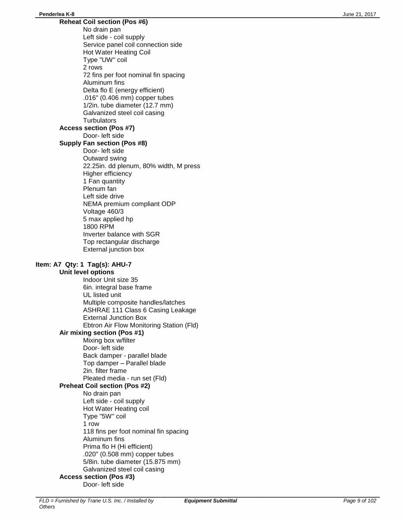
Supply Fan section (Pos #8) Door- right side 20in. dd plenum, full width, M press 1 Fan quantity Plenum fan Right side drive NEMA premium compliant ODP Voltage 460/3 10 max applied hp 1800 RPM Inverter balance with SGR Top rectangular discharge External junction box Item: A6 Qty: 1 Tag(s): AHU-6 Unit level options Indoor Unit size 12 6in. integral base frame UL listed unit Multiple composite handles/latches ASHRAE 111 Class 6 Casing Leakage External Junction Box Ebtron Air Flow Monitoring Station (Fld) Air mixing section (Pos #1) Mixing box w/filter Door- left side Back damper - parallel blade Top damper - parallel blade 2in. filter frame with Pleated media - run set (Fld) Preheat Coil section (Pos #2) No drain pan Left side - coil supply Service panel coil connection side Hot Water Heating coil Type "5W" coil 1 row 80 fins per foot nominal fin spacing Aluminum fins Prima flo H (Hi efficient) .020" (0.508 mm) copper tubes 5/8in. tube diameter (15.875 mm) Galvanized steel coil casing Access section (Pos #3) Door- left side Cooling Coil section (Pos #4) Stainless steel drain pan Left side - drain connection Left side - coil supply Service panel coil connection side Chilled Water Cooling Coil Type "UW" coil 6 rows 105 fins per foot nominal fin spacing Aluminum fins Delta flo H (Hi efficient) .016" (0.406 mm) copper tubes 1/2in. tube diameter (12.7 mm) Galvanized steel coil casing Turbulators Access section (Pos #5) Door- left side
Penderlea K-8 June 21, 2017
FLD = Furnished by Trane U.S. Inc. / Installed by Others
Equipment Submittal Page 9 of 102
Reheat Coil section (Pos #6) No drain pan Left side - coil supply Service panel coil connection side Hot Water Heating Coil Type "UW" coil 2 rows 72 fins per foot nominal fin spacing Aluminum fins Delta flo E (energy efficient) .016" (0.406 mm) copper tubes 1/2in. tube diameter (12.7 mm) Galvanized steel coil casing Turbulators Access section (Pos #7) Door- left side Supply Fan section (Pos #8) Door- left side Outward swing 22.25in. dd plenum, 80% width, M press Higher efficiency 1 Fan quantity Plenum fan Left side drive NEMA premium compliant ODP Voltage 460/3 5 max applied hp 1800 RPM Inverter balance with SGR Top rectangular discharge External junction box Item: A7 Qty: 1 Tag(s): AHU-7 Unit level options Indoor Unit size 35 6in. integral base frame UL listed unit Multiple composite handles/latches ASHRAE 111 Class 6 Casing Leakage External Junction Box Ebtron Air Flow Monitoring Station (Fld) Air mixing section (Pos #1) Mixing box w/filter Door- left side Back damper - parallel blade Top damper – Parallel blade 2in. filter frame Pleated media - run set (Fld) Preheat Coil section (Pos #2) No drain pan Left side - coil supply Hot Water Heating coil Type "5W" coil 1 row 118 fins per foot nominal fin spacing Aluminum fins Prima flo H (Hi efficient) .020" (0.508 mm) copper tubes 5/8in. tube diameter (15.875 mm) Galvanized steel coil casing Access section (Pos #3) Door- left side

Penderlea K-8 June 21, 2017
FLD = Furnished by Trane U.S. Inc. / Installed by Others
Equipment Submittal Page 10 of 102
Cooling Coil section (Pos #4)
Stainless steel drain pan Left side - drain connection Left side - coil supply Chilled Water Cooling coil Type "UW" coil 8 rows 72 fins per foot nominal fin spacing Aluminum fins Delta flo E (energy efficient) .016" (0.406 mm) copper tubes 1/2in. tube diameter (12.7 mm) Galvanized steel coil casing Access section (Pos #5) Door- left side Reheat Coil section (Pos #6) No drain pan Left side - coil supply Hot Water Heating coil Type "UW" coil 2 rows 72 fins per foot nominal fin spacing Aluminum fins Delta flo E (energy efficient) .016" (0.406 mm) copper tubes 1/2in. tube diameter (12.7 mm) Galvanized steel coil casing Access section (Pos #7) Door- left side Supply Fan section (Pos #8) Door- left side 22.25in. dd plenum, full width, M press 2 Fan quantity Plenum fan Left side drive NEMA premium compliant ODP Voltage 460/3 10 max applied hp 1800 RPM Inverter balance with SGR Top rectangular discharge External junction box Item: A8 Qty: 1 Tag(s): AHU-8 Unit level options Indoor Unit size 6 6in. integral base frame UL listed unit Multiple composite handles/latches ASHRAE 111 Class 6 Casing Leakage External Junction Box Ebtron Air Flow Monitoring Station (Fld) Air mixing section (Pos #1) Mixing box w/filter Door- right side Back damper - parallel blade Top damper - low flow TRAQ 2in. filter frame Pleated media - run set (Fld)

Penderlea K-8 June 21, 2017
FLD = Furnished by Trane U.S. Inc. / Installed by Others
Equipment Submittal Page 11 of 102
Chilled Water Coil section (Pos #2) Stainless steel drain pan Right side - drain connection Right side - coil supply Chilled Water Cooling coil Type "UW" coil 6 rows 111 fins per foot nominal fin spacing Aluminum fins Delta flo E (energy efficient) .016" (0.406 mm) copper tubes 1/2in. tube diameter (12.7 mm) Galvanized steel coil casing Turbulators Access section (Pos #3) Door- right side Reheat Coil section (Pos #4) No drain pan Right side - coil supply Hot Water Heating coil Type "UW" coil 2 rows 81 fins per foot nominal fin spacing Aluminum fins Delta flo E (energy efficient) .016" (0.406 mm) copper tubes 1/2in. tube diameter (12.7 mm) Galvanized steel coil casing Turbulators Access section (Pos #5) Door- right side Supply Fan section (Pos #6) Door- right side 16.5in. dd plenum, 80% width, M press 1 Fan quantity Plenum fan Right side drive NEMA premium compliant ODP Voltage 460/3 5 max applied hp 1800 RPM Inverter balance with SGR Top rectangular discharge External junction box

Penderlea K-8 June 21, 2017
FLD = Furnished by Trane U.S. Inc. / Installed by Others
Equipment Submittal Page 12 of 102
Performance Data - Performance Climate Changer
Tags AHU-1 AHU-2 AHU-3
Fan section
Position #6 #6 #6
Fan airflow (cfm) 15400 16000 17200
Overall ESP (in H2O) 2.500 2.500 2.500
Total static pressure (in H2O) 3.938 4.010 3.787
Fan pressure drop (in H2O) 2.701 2.717 2.751
Speed (rpm) 2072 2145 1941
Total brake horsepower (hp) 15.522 17.528 16.709
Unit static efficiency (%) 61.59 57.71 61.45
Motor hertz (Hz) 70 73 66
Discharge 1 front - airflow (cfm) - 16000 17200
Discharge 1 front - face velocity (ft/min) 1136 1180 1269
Discharge 1 front - pressure drop (in H2O) 0.201 0.217 0.251
Discharge 1 front - area (sq ft) 13.56 13.56 13.56
Coil section
Position #2 #4 #2 #4 #2 #4
Coil performance airflow (cfm) 15400 15400 16000 16000 17200 17200
Total capacity (MBh) 592.40 554.93 575.44 573.59 627.00 628.26
Sensible capacity (MBh) - 407.42 - 423.29 - 457.40
Entering dry bulb (F) 20.00 80.00 20.00 80.00 20.00 80.00
Entering wet bulb (F) - 67.00 - 67.00 - 67.00
Leaving dry bulb (F) 55.47 56.00 53.16 56.00 53.61 55.88
Leaving wet bulb (F) - 55.45 - 55.51 - 55.27
Entering fluid temperature (F) 180.00 44.00 180.00 44.00 180.00 44.00
Leaving fluid temperature (F) 140.00 58.75 140.00 59.25 140.00 59.66
Fluid temperature rise (F) - 14.75 - 15.25 - 15.66
Fluid temperature drop (F) 40.00 - 40.00 - 40.00 -
Standard fluid flow rate (gpm) 29.61 75.00 28.76 75.00 31.34 80.00
Fluid pressure drop (ft H2O) 2.99 6.64 2.85 6.63 3.30 9.32
Fluid velocity (ft/s) 1.82 2.86 1.77 2.86 1.92 3.05
Fluid volume (gal) 5.12 22.44 5.12 22.44 5.12 29.09
Coil face area (sq ft) 32.63 34.94 32.63 34.94 32.63 34.94
Coil face velocity (ft/min) 472 441 490 458 527 492
Air pressure drop (in H2O) 0.064 0.525 0.065 0.570 0.078 0.713
Air mixing section
Position #1 #1 #1
Opening 1 back - airflow (cfm) 15400 16000 17200
Opening 1 back - area (sq ft) 14.32 14.32 14.32
Opening 1 back - face velocity (ft/min) 1075 1117 1201
Opening 1 back - pressure drop (in H2O) 0.094 0.101 0.117
Opening 1 top - airflow (cfm) 15400 16000 17200
Opening 1 top - area (sq ft) 14.32 14.32 14.32
Opening 1 top - face velocity (ft/min) 1075 1117 1201
Opening 1 top - pressure drop (in H2O) 0.094 0.101 0.117
Filter condition Mid-life Mid-life Clean
Filter airflow (cfm) 15400 16000 17200
Filter area (sq ft) 63.33 63.33 63.33
Filter face velocity (ft/min) 243 253 272
Filter pressure drop (in H2O) 0.553 0.557 0.128
Total mixing section pressure drop (in H2O) 0.647 0.658 0.245
Top total pressure drop (in H2O) 0.094 0.101 0.117

Penderlea K-8 June 21, 2017
FLD = Furnished by Trane U.S. Inc. / Installed by Others
Equipment Submittal Page 13 of 102
Tags AHU-4 AHU-5 AHU-6
Fan section
Position #6 #8 #8
Fan airflow (cfm) 16500 7000 5600
Overall ESP (in H2O) 2.500 1.250 1.250
Total static pressure (in H2O) 4.202 3.261 3.140
Fan pressure drop (in H2O) 2.731 1.552 1.559
Speed (rpm) 1947 2114 1670
Total brake horsepower (hp) 17.148 6.178 4.263
Unit static efficiency (%) 63.75 58.25 65.03
Motor hertz (Hz) 66 72 57
Discharge 1 front - airflow (cfm) 16500 - -
Discharge 1 front - face velocity (ft/min) 1217 - -
Discharge 1 front - pressure drop (in H2O) 0.231 - -
Discharge 1 front - area (sq ft) 13.56 - -
Discharge 1 top - airflow (cfm) - 7000 5600
Discharge 1 top - face velocity (ft/min) - 1557 1575
Discharge 1 top - pressure drop (in H2O) - 0.302 0.309
Discharge 1 top - area (sq ft) - 4.50 3.56
Coil section
Position #2 #4 #2 #4 #6 #2
Coil performance airflow (cfm) 16500 16500 7000 7000 7000 5600
Total capacity (MBh) 613.86 642.88 240.72 254.01 303.00 185.17
Sensible capacity (MBh) - 460.01 - 185.19 - -
Entering dry bulb (F) 20.00 80.00 20.00 80.00 55.00 20.00
Entering wet bulb (F) - 67.00 - 67.00 - -
Leaving dry bulb (F) 54.30 54.71 51.71 56.00 94.91 50.49
Leaving wet bulb (F) - 54.38 - 55.36 - -
Entering fluid temperature (F) 180.00 44.00 180.00 44.00 180.00 180.00
Leaving fluid temperature (F) 140.00 60.02 140.00 58.47 140.00 140.00
Fluid temperature rise (F) - 16.02 - 14.47 - -
Fluid temperature drop (F) 40.00 - 40.00 - 40.00 40.00
Standard fluid flow rate (gpm) 30.68 80.00 12.03 35.00 15.14 9.26
Fluid pressure drop (ft H2O) 3.18 9.32 1.17 8.58 0.35 0.29
Fluid velocity (ft/s) 1.88 3.05 1.33 2.40 1.04 1.02
Fluid volume (gal) 5.12 29.09 2.25 8.79 3.59 2.10
Coil face area (sq ft) 32.63 34.94 12.50 13.65 13.65 11.25
Coil face velocity (ft/min) 506 472 560 513 513 498
Air pressure drop (in H2O) 0.072 0.732 0.086 0.672 0.148 0.070
Air mixing section
Position #1 #1 #1
Opening 1 back - airflow (cfm) 16500 7000 5600
Opening 1 back - area (sq ft) 14.32 5.66 5.10
Opening 1 back - face velocity (ft/min) 1152 1237 1098
Opening 1 back - pressure drop (in H2O) 0.108 0.197 0.218
Opening 1 top - airflow (cfm) 16500 7000 5600
Opening 1 top - area (sq ft) 14.32 5.66 5.10
Opening 1 top - face velocity (ft/min) 1152 1237 1098
Opening 1 top - pressure drop (in H2O) 0.108 0.197 0.218
Filter condition Mid-life Mid-life Mid-life
Filter area (sq ft) 63.33 18.06 16.67
Filter face velocity (ft/min) 261 388 336
Filter pressure drop (in H2O) 0.559 0.605 0.586
Total mixing section pressure drop (in H2O) 0.667 0.803 0.805
Back total pressure drop (in H2O) 0.108 0.197 0.218
Top total pressure drop (in H2O) 0.108 0.197 0.218

Penderlea K-8 June 21, 2017
FLD = Furnished by Trane U.S. Inc. / Installed by Others
Equipment Submittal Page 14 of 102
Tags AHU-6 AHU-7 AHU-8
Fan section
Position #8 #6
Fan airflow (cfm) 15800 3100
Overall ESP (in H2O) 1.250 1.250
Total static pressure (in H2O) 2.900 3.330
Fan pressure drop (in H2O) 1.432 1.500
Speed (rpm) 1746 2474
Total brake horsepower (hp) 12.039 2.865
Unit static efficiency (%) 60.00 56.81
Motor hertz (Hz) 59 84
Discharge 1 top - airflow (cfm) 15800 -
Discharge 1 top - face velocity (ft/min) 1207 1417
Discharge 1 top - pressure drop (in H2O) 0.182 0.250
Discharge 1 top - area (sq ft) 13.09 2.19
Coil section
Position #4 #6 #2 #4 #6 #2 #4
Coil performance airflow (cfm) 5600 5600 15800 15800 15800 3100 3100
Total capacity (MBh) 215.02 265.85 600.32 605.49 703.14 110.99 134.50
Sensible capacity (MBh) 154.32 - - 432.73 - 82.01 -
Entering dry bulb (F) 80.00 50.00 20.00 80.00 56.00 80.00 55.00
Entering wet bulb (F) 67.00 - - 67.00 - 67.00 -
Leaving dry bulb (F) 55.00 93.77 55.03 55.15 97.03 56.00 95.01
Leaving wet bulb (F) 54.59 - - 54.62 - 55.53 -
Entering fluid temperature (F) 44.00 180.00 180.00 44.00 180.00 44.00 180.00
Leaving fluid temperature (F) 58.97 140.00 140.00 59.09 140.00 57.83 140.00
Fluid temperature rise (F) 14.97 - - 15.09 - 13.83 -
Fluid temperature drop (F) - 40.00 40.00 - 40.00 - 40.00
Standard fluid flow rate (gpm) 28.63 13.29 30.01 80.00 35.14 16.00 6.72
Fluid pressure drop (ft H2O) 5.62 0.81 3.06 9.33 0.73 2.39 0.54
Fluid velocity (ft/s) 1.96 0.91 1.84 3.05 1.34 1.37 0.58
Fluid volume (gal) 8.06 3.35 5.12 29.09 9.15 4.10 1.69
Coil face area (sq ft) 12.30 12.30 32.63 34.94 34.94 6.11 6.11
Coil face velocity (ft/min) 455 455 484 452 452 508 508
Air pressure drop (in H2O) 0.590 0.116 0.067 0.632 0.115 0.696 0.144
Air mixing section
Position #1 #1
Opening 1 back - airflow (cfm) 15800 3100
Opening 1 back - area (sq ft) 14.32 2.45
Opening 1 back - face velocity (ft/min) 1103 1265
Opening 1 back - pressure drop (in H2O) 0.099 0.399
Opening 1 top - airflow (cfm) 15800 3100
Opening 1 top - area (sq ft) 14.32 2.45
Opening 1 top - face velocity (ft/min) 1103 1265
Opening 1 top - pressure drop (in H2O) 0.099 0.399
Greatest entry PD (in H2O) 0.099 0.399
Filter condition Mid-life Mid-life
Filter area (sq ft) 63.33 8.89
Filter face velocity (ft/min) 249 349
Filter pressure drop (in H2O) 0.556 0.591
Total mixing section pressure drop (in H2O) 0.655 0.990
Back total pressure drop (in H2O) 0.099 0.399
Top total pressure drop (in H2O) 0.099 0.399

Penderlea K-8 June 21, 2017
FLD = Furnished by Trane U.S. Inc. / Installed by Others
Equipment Submittal Page 15 of 102
Mechanical Specifications - Performance Climate Changer Item: A1 - A8 Qty: 8 Tag(s): AHU-1, AHU-2, AHU-3, AHU-4, AHU-5, AHU-6, AHU-7, AHU-8 GENERAL Per ASHRAE 62.1 recommendation, indoor air handling units will be shipped stretch-wrapped to protect unit from in-transit rain and debris. Installing contractor is responsible for long term storage in accordance with the Installation, Operation, and Maintenance manual (CLCH-SVX07B-EN). Unit shall be UL and C-UL Listed. Supply fans within the scope of AHRI Standard 430 shall be certified in accordance with AHRI Standard 430. Unit sound performance data shall be provided using AHRI Standard 260 test methods and reported as sound power. Trane, in providing this program and data, does not certify or warrant NC levels. These levels are affected by factors specific to each application and/or installation and therefore unable to be predicted or certified by Trane. Refer to product data for specific fan footnote references. - Footnote 2: Predictions for dual fan units in single fan operation based on a single fan unit. - Footnote 4: Sound Power Levels are in accordance with AHRI 260. Unit Construction All unit panels shall be 2" solid, double-wall construction to facilitate cleaning of unit interior. Unit panels shall be provided with a mid-span, no-through-metal, internal thermal break. Casing thermal performance shall be such that under 55°F supply air temperature and design conditions on the exterior of the unit of 81°F dry bulb and 73°F wet bulb, condensation shall not form on the casing exterior. All exterior and interior indoor AHU panels will be made of galvanized steel. Unit Paint Unit to ship unpainted from factory. If required, unit to be painted by 3rd party finisher, or by painting contractor at job site. Casing Deflection The casing shall not exceed 0.0042 inch deflection per inch of panel span at 1.00 times design static pressure. Maximum design static shall not exceed +8 inches w.g. in all positive pressure sections and -8 inches w.g. in all negative pressure sections. Floor Construction The unit floor shall be of sufficient strength to support a 300.0 lb load during maintenance activities and shall deflect no more than 0.0042 inch per inch of panel span. Unit base Manufacturer to provide a full perimeter integral base frame for either ceiling suspension of units or to support and raise all sections of the unit for proper trapping. Indoor unit base frame will either be bolted construction or welded construction. All outdoor unit base frames shall be welded construction. For indoor units, refer to schedule for base height and construction type. Contractor will be responsible for providing a housekeeping pad when unit base frame is not of sufficient height to properly trap unit. Unit base frames not constructed of galvanized steel shall be chemically cleaned and coated with both a rust-inhibiting primer and finished coat of rust-inhibiting enamel. Unit base height to be included in total height required for proper trap height. Insulation Panel insulation shall provide a minimum thermal resistance (R) value of 13 ft²-h-ºF/Btu throughout the entire unit. Insulation shall completely fill the panel cavities in all directions so that no voids exist and settling of insulation is prevented. Panel insulation shall comply with NFPA 90A. Drain Pan In sections provided with a drain pan, the drain pan shall be designed in accordance with ASHRAE 62.1. To address indoor air quality (IAQ) the drain pan shall be sloped in two planes promoting positive drainage to eliminate stagnant water conditions. Drain pan shall be insulated, and of double wall construction. The outlet shall be the lowest point on

Penderlea K-8 June 21, 2017
FLD = Furnished by Trane U.S. Inc. / Installed by Others
Equipment Submittal Page 16 of 102
the pan, and shall be of sufficient diameter to preclude drain pan overflow under normally expected operating conditions. All drain pans connections shall have a threaded connection, extending a minimum of 2-1/2" beyond the unit base, and shall be made from the same material as the drain pan. Drain pan located under a cooling coil shall be of sufficient size to collect all condensate produced from the coil. Refer to Product Data for specific information on which sections are supplied with a drain pan, the drain pan material and connection location. Access Door Construction Access doors shall be 2" double wall construction. Interior and exterior door panels shall be of the same construction as the interior and exterior wall panels respectively. All doors shall be provided with a thermal break construction of door panel and door frame. Gasketing shall be provided around the full perimeter of the doors to prevent air leakage. Surface mounted handles shall be provided to allow quick access to the interior of the functional section and to prevent through cabinet penetrations that could likely weaken the casing leakage and thermal performance. Handle hardware shall be designed to prevent unintended closure. Access doors shall be hinged and removable for quick easy access. Hinges shall be interchangeable with the door handle hardware to allow for alternating door swing in the field to minimize access interference due to unforeseen job site obstructions. Door handle hardware shall be adjustable and visually indicate locking position of door latch external to the section. Door hinges shall be galvanized. All doors shall be a minimum of 60" high when sufficient height is available or the maximum height allowed by the unit height. Door handles shall be provided for each latching point of the door necessary to maintain the specified air leakage integrity of the unit. Optionally for indoor AHUs and as standard on outdoor AHUs, outward swing doors are provided with a single handle linked to multiple latching points. An optional shatterproof window shall be provided in access doors where indicated on the plans. Window shall either be single pane, or thermal dual pane, as defined on schedule. Window shall be capable of withstanding unit operating pressures and shall be safe for viewing UV-C lamps. Refer to Product Data for specific information on which sections are supplied with an access door, the door location, a single handle and a window. MIXING SECTION A mixing section shall be provided to support the damper assembly for outdoor, return, and/or exhaust air. Dampers Dampers shall modulate the volume of outdoor, return, or exhaust air. The dampers shall be of double-skin airfoil design with metal, compressible jamb seals and flexible blade-edge seals on all blades. The blades shall rotate on stainless-steel sleeve bearings. The dampers shall be rated for a maximum leakage rate of 3 cfm/ft² at 1 in. w.g. complying with ASHRAE 90.1 maximum damper leakage. All leakage testing and pressure ratings shall be based on AMCA Standard 500-D. Dampers may be arranged in a parallel or opposed-blade configuration. Dampers Dampers shall modulate the volume of outdoor, return, or exhaust air. The dampers shall be of double-skin airfoil design with metal, compressible jamb seals and flexible blade-edge seals on all blades. The blades shall rotate on stainless-steel sleeve bearings. The dampers shall be rated for a maximum leakage rate of 3 cfm/ft² at 1 in. w.g. complying with ASHRAE 90.1 maximum damper leakage. All leakage testing and pressure ratings shall be based on AMCA Standard 500-D. Dampers may be arranged in a parallel or opposed-blade configuration. The following specifications apply only to units with outside air and return air dampers, with actuators. The 5 year warranty applies only to these items. This unit contains Economizer that meets or exceeds all mandatory requirements prescribed by Title 24, including but not limited to: - 5 yr parts only warranty - Successfully tested to 60,000 Actuations - Less than 10 cfm/sq.ft. of damper leakage at 1" WG per AMCA 500L Filters Mixing sections shall be provided with a filter rack as indicated in the Product Data and As-Built sections of the submittal. 2-inch pleated media filters made with 100% synthetic fibers that are continuously laminated to a supported steel-wire grid with water repellent adhesive shall be provided. Filters shall be capable of operating up to 625 fpm face velocity without loss of filter efficiency and holding capacity. The filters shall have a MERV 8 rating when tested in accordance with the ANSI/ASHRAE Standard 52.2.
Penderlea K-8 June 21, 2017
FLD = Furnished by Trane U.S. Inc. / Installed by Others
Equipment Submittal Page 17 of 102
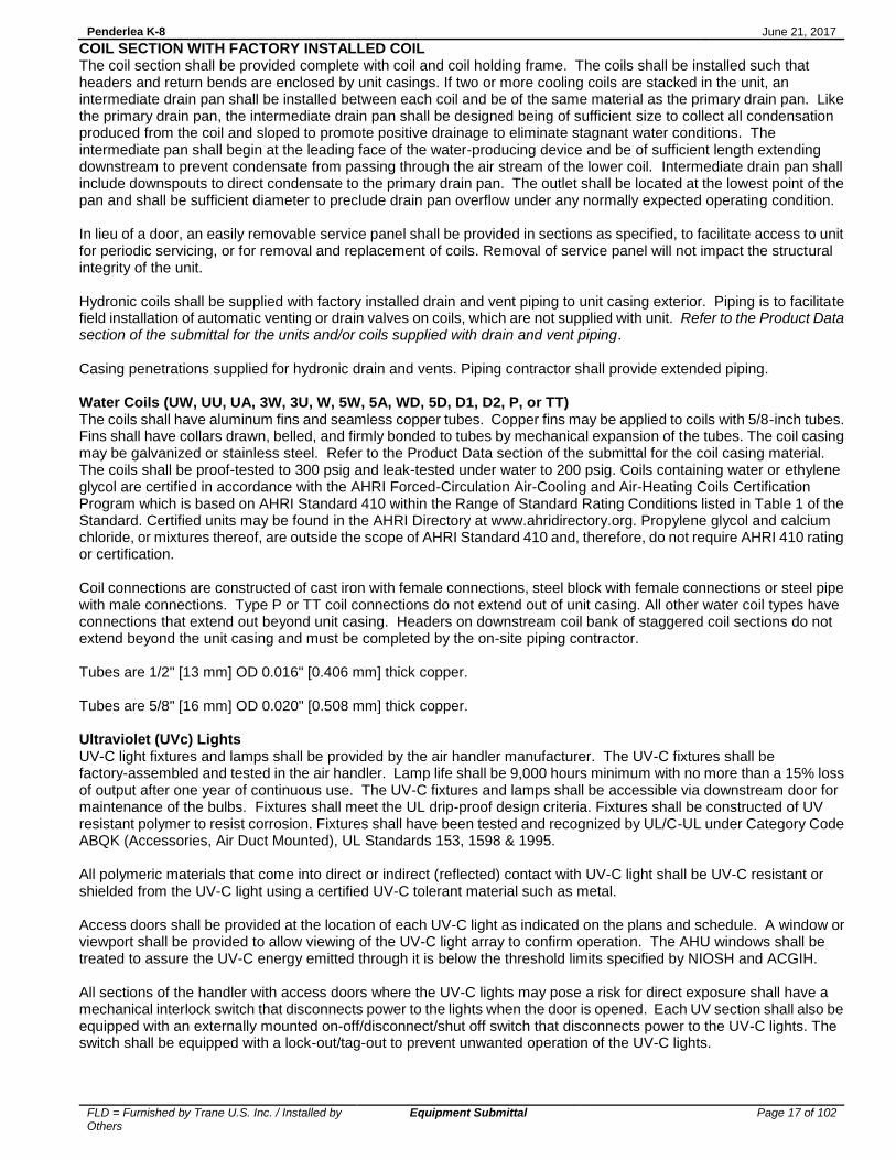
COIL SECTION WITH FACTORY INSTALLED COIL The coil section shall be provided complete with coil and coil holding frame. The coils shall be installed such that headers and return bends are enclosed by unit casings. If two or more cooling coils are stacked in the unit, an intermediate drain pan shall be installed between each coil and be of the same material as the primary drain pan. Like the primary drain pan, the intermediate drain pan shall be designed being of sufficient size to collect all condensation produced from the coil and sloped to promote positive drainage to eliminate stagnant water conditions. The intermediate pan shall begin at the leading face of the water-producing device and be of sufficient length extending downstream to prevent condensate from passing through the air stream of the lower coil. Intermediate drain pan shall include downspouts to direct condensate to the primary drain pan. The outlet shall be located at the lowest point of the pan and shall be sufficient diameter to preclude drain pan overflow under any normally expected operating condition. In lieu of a door, an easily removable service panel shall be provided in sections as specified, to facilitate access to unit for periodic servicing, or for removal and replacement of coils. Removal of service panel will not impact the structural integrity of the unit. Hydronic coils shall be supplied with factory installed drain and vent piping to unit casing exterior. Piping is to facilitate field installation of automatic venting or drain valves on coils, which are not supplied with unit. Refer to the Product Data section of the submittal for the units and/or coils supplied with drain and vent piping. Casing penetrations supplied for hydronic drain and vents. Piping contractor shall provide extended piping. Water Coils (UW, UU, UA, 3W, 3U, W, 5W, 5A, WD, 5D, D1, D2, P, or TT) The coils shall have aluminum fins and seamless copper tubes. Copper fins may be applied to coils with 5/8-inch tubes. Fins shall have collars drawn, belled, and firmly bonded to tubes by mechanical expansion of the tubes. The coil casing may be galvanized or stainless steel. Refer to the Product Data section of the submittal for the coil casing material. The coils shall be proof-tested to 300 psig and leak-tested under water to 200 psig. Coils containing water or ethylene glycol are certified in accordance with the AHRI Forced-Circulation Air-Cooling and Air-Heating Coils Certification Program which is based on AHRI Standard 410 within the Range of Standard Rating Conditions listed in Table 1 of the Standard. Certified units may be found in the AHRI Directory at www.ahridirectory.org. Propylene glycol and calcium chloride, or mixtures thereof, are outside the scope of AHRI Standard 410 and, therefore, do not require AHRI 410 rating or certification. Coil connections are constructed of cast iron with female connections, steel block with female connections or steel pipe with male connections. Type P or TT coil connections do not extend out of unit casing. All other water coil types have connections that extend out beyond unit casing. Headers on downstream coil bank of staggered coil sections do not extend beyond the unit casing and must be completed by the on-site piping contractor. Tubes are 1/2" [13 mm] OD 0.016" [0.406 mm] thick copper. Tubes are 5/8" [16 mm] OD 0.020" [0.508 mm] thick copper. Ultraviolet (UVc) Lights UV-C light fixtures and lamps shall be provided by the air handler manufacturer. The UV-C fixtures shall be factory-assembled and tested in the air handler. Lamp life shall be 9,000 hours minimum with no more than a 15% loss of output after one year of continuous use. The UV-C fixtures and lamps shall be accessible via downstream door for maintenance of the bulbs. Fixtures shall meet the UL drip-proof design criteria. Fixtures shall be constructed of UV resistant polymer to resist corrosion. Fixtures shall have been tested and recognized by UL/C-UL under Category Code ABQK (Accessories, Air Duct Mounted), UL Standards 153, 1598 & 1995. All polymeric materials that come into direct or indirect (reflected) contact with UV-C light shall be UV-C resistant or shielded from the UV-C light using a certified UV-C tolerant material such as metal. Access doors shall be provided at the location of each UV-C light as indicated on the plans and schedule. A window or viewport shall be provided to allow viewing of the UV-C light array to confirm operation. The AHU windows shall be treated to assure the UV-C energy emitted through it is below the threshold limits specified by NIOSH and ACGIH. All sections of the handler with access doors where the UV-C lights may pose a risk for direct exposure shall have a mechanical interlock switch that disconnects power to the lights when the door is opened. Each UV section shall also be equipped with an externally mounted on-off/disconnect/shut off switch that disconnects power to the UV-C lights. The switch shall be equipped with a lock-out/tag-out to prevent unwanted operation of the UV-C lights.

Penderlea K-8 June 21, 2017
FLD = Furnished by Trane U.S. Inc. / Installed by Others
Equipment Submittal Page 18 of 102
ACCESS/INSPECTION / TURNING SECTION A section shall be provided to allow additional access/inspection of unit components and space for field-installed components as needed. An access door shall be provided for easy access. All access sections shall be complete with a double-wall, removable door downstream for inspection, cleaning, and maintenance. Interior and exterior door panels shall be of the same construction as the interior and exterior wall panels, respectively. All doors downstream of cooling coils shall be provided with a thermal break construction of door panel and door frame. Fans that are selected with inverter balancing shall first be dynamically balanced at design RPM. The fans then will be checked in the factory from 25% to 100% of design RPM to insure they are operating within vibration tolerance specifications, and that there are no resonant frequency issues throughout this operating range. Inverter balancing that requires lockout frequencies inputted into a variable frequency drive to in order to bypass resonant frequencies shall not be acceptable. If supplied in this manner by the unit manufacturer, the contractor will be responsible for rebalancing in the field after unit installation. Fans selected with inverter balancing shall have a maintenance free grounding assembly installed on the fan motor to discharge both static and induced shaft currents to ground. DIRECT-DRIVE PLENUM FAN SECTION The fan type shall be provided as required for stable operation and optimum energy efficiency. The fan shall be a single-width, single-inlet, multiblade-type direct-drive plenum fan. Motor bearing life of the direct-drive plenum fan shall be not less than L-10 250,000 hrs. Refer to the Product Data section for fan quantity and number of blades selected within each unit. Fans shall be certified as complying with AHRI Standard 430 for airflow performance. Fans shall be tested and rated in-accordance with AHRI Standard 260 for sound performance. On units supplied with plenum or motorized impeller fans, expanded metal door guard(s) shall be supplied on the access door(s) to the fan and those downstream access door(s) where unintended access to the plenum or motorized impeller fan could occur. Door guard is intended to deter unauthorized entry and incidental contact with rotating components. Refer to the Product Data section for fans with access door guard(s). Motor Frame The motor shall be mounted integral to the isolated fan assembly and furnished by the unit manufacturer. The motor is mounted inside the unit casing on an adjustable base to permit adjustment of drive belt tension (not applicable for direct drive plenum fans). The motor shall meet or exceed all NEMA Standards Publication MG 1 requirements and comply with NEMA Premium efficiency levels when applicable except for fractional horsepower motors which are not covered by the NEMA classification. The motor shall be T-frame, squirrel cage with size, type, and electrical characteristics as shown on the equipment schedule. Refer to the Product Data section for selected fan motors within each unit. Two-Inch Spring Isolators Direct-drive fan and motor assemblies shall be internally isolated from the unit casing with 2-inch (50.8 mm) deflection spring isolators. The isolation system shall be designed to resist loads produced by external forces, such as earthquakes, and conform to the current IBC seismic requirements. Design VFD frequency is less than line frequency. Use caution during startup to ensure the VFD will not operate at the line frequency, or ensure that the air delivery system can handle being over-pressurized. Indoor Units with an External Motor Junction Box The fan section shall have motor leads extended to a factory-installed NEMA external junction box to facilitate field supplied starter or VFD wiring and to maintain air leakage integrity of the casing. For units with a full-load amp rating less than or equal to 110 amps, the enclosure shall be a NEMA 1 enclosure. For units with a full-load amp rating greater than 110 amps, the enclosure shall be a NEMA 4 enclosure. Refer to the Product Data section for fans with an external motor junction box. Overload box Overload panel is a factory mounted NEMA type 1 enclosure for indoor units, and NEMA type 4 enclosure for outdoor units. The panel will take one field VFD power input and distribute to 2, 4 or 6 fans. These fans will be protected by manual motor protectors, one per fan. Auxiliary contacts are wired in series to terminal blocks for generic trip signaling. Panel is rated for WYE power systems up to 600V. Lifting Instructions The air handling units must be rigged, lifted, and installed in strict accordance with the Installation, Operation, and Maintenance manual (CLCH-SVX07G-EN). The units are also to be installed in strict accordance with the specifications. Units may be shipped fully assembled or disassembled to the minimum functional section size in accordance with shipping and job site requirements. Indoor units shall be shipped on an integral base frame (variable from the standard 2.5" to 8" height) for the purpose of

Penderlea K-8 June 21, 2017
FLD = Furnished by Trane U.S. Inc. / Installed by Others
Equipment Submittal Page 19 of 102
mounting units to a housekeeping pad and providing additional height to properly trap condensate from the unit. The integral base frame may be used for ceiling suspension, external isolation, or as a housekeeping pad. Indoor sizes 3 to 30 will also be shipped with a shipping skid designed for forklift transport. Refer to the unit As-Built or Product Data section of the submittal for the base frame height of each unit. All units will be shipped with an integral base frame designed with the necessary number of lift points for safe installation. All lifting lugs are to be utilized during lift. The lift points will be designed to accept standard rigging devices and be removable after installation. Units shipped in sections will have a minimum of four points of lift.

Penderlea K-8 June 21, 2017
FLD = Furnished by Trane U.S. Inc. / Installed by Others
Equipment Submittal Page 20 of 102
As-Built - Performance Climate Changer Item: A1 Qty: 1 Tag(s): AHU-1
OP
EN
ING
AN
D D
IME
NS
ION
S M
AY
VA
RY
FR
OM
CO
NT
RA
CT
DO
CU
ME
NT
S / R
ET
UR
N O
F A
PP
RO
VE
D D
RA
WIN
GS
CO
NS
TIT
UT
ES
AC
CE
PT
AN
CE
OF
TH
ES
E V
AR
IAN
CE
S / N
OT
TO
SC
AL
E
Unit s
ize
: 3
5
Pro
du
ct g
rou
p: In
do
or
unit
Inte
gra
l b
ase
fra
me
: 6
in. in
teg
ral b
ase
fra
me
Pa
int: U
np
ain
ted
/fie
ld p
ain
ted
Jo
b N
am
e:
Actu
al a
irflo
w: 1
54
00
cfm
Sa
les O
ffic
e:
Un
it C
asin
g: 2in
Do
ub
le W
all
Fo
am
Pro
po
sa
l N
um
be
r:
Rig
gin
g/In
sta
lled
We
igh
t: 4
18
5.5
lb
/ 4
41
5.7
lb
Perform
ance C
limate
Changer
Air H
andle
rs
22"
10"
15"
20"
15 1
/2
69
19 1
/2
61
7 7
/83
1/4
100
12
34
56
78
6 2
1 1
/8
34 1
/4
22 3
/8
32
46 3
/4
5 1
/2
34 1
/220 1
/8
78 5
/82 3
/4
6 1
/23
4 1
/4
1.2
5"
N.P
.T.E
10
11
75 5
/8S
hip
Sp
lit1875
lb
s
91 1
/8S
hip
Split
247
6 lbs
166 5
/8
70 3
/4
1 2 3 4 5 6 7 8 9 10
11
Op
enin
g f
ront
32.0
00 x
61.0
00
Ple
num
fan -
22
.25
in.
dd
ple
num
, 8
0%
wid
th,
Mpre
ss S
upp
ly f
an 1
0 h
p460/3
Overl
oad b
ox R
HU
V lig
ht
sw
itch R
HC
oolin
g c
oil
- 6
Coil
type
UW
Heating
coil
- 1
C
oil
type
5W
Dam
per
top-p
ara
llel b
lade
34.2
50 x
69.0
00
Dam
per
back-p
ara
llel
bla
de
34.2
50 x
69.0
00
1.2
5"
N.P
.T.E
UV
lig
ht
rack
Angle
d f
ilters
-
Doors
22 w
idth
x 6
1 h
eig
ht
15 w
idth
x 6
1 h
eig
ht
10 w
idth
x 6
1 h
eig
ht
20 w
idth
x 6
1 h
eig
ht
Fo
r m
an
eu
veri
ng
pu
rpo
ses,
inclu
de 1
.125 i
nch
es t
o e
ach
sh
ip s
pli
t le
ng
th f
or
overl
ap
pin
g p
an
el
flan
ge.
Fla
ng
e w
ill
no
t ad
d t
o o
vera
ll i
nsta
lled
un
it l
en
gth
sh
ow
n.
Penderlea K-8 June 21, 2017
FLD = Furnished by Trane U.S. Inc. / Installed by Others
Equipment Submittal Page 21 of 102
As-Built - Performance Climate Changer Item: A1 Qty: 1 Tag(s): AHU-1
OPENING AND DIMENSIONS MAY VARY FROM CONTRACT DOCUMENTS / RETURN OF APPROVED DRAWINGS CONSTITUTES ACCEPTANCE OF THESE VARIANCES / NOT TO SCALE
Unit size: 35
Product group: Indoor unit
Integral base frame: 6in. integral base frame
Paint: Unpainted/field painted
Job Name:
Actual airflow: 15400 cfm
Sales Office:
Unit Casing: 2in Double Wall Foam
Proposal Number:
Rigging/Installed Weight: 4185.5 lb/ 4415.7 lb
Performance Climate Changer
Air Handlers
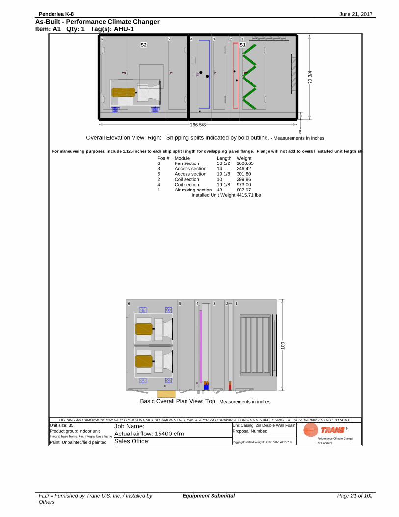
Pos #635241
ModuleFan sectionAccess sectionAccess sectionCoil sectionCoil sectionAir mixing section
Length56 1/214 19 1/810 19 1/848
Weight1606.65246.42301.80399.86973.00887.97
Installed Unit Weight 4415.71 lbs
6 35 24 1
100
Basic Overall Plan View: Top - Measurements in inches
S2 S1
6
6 35 24 1
166 5/8
70
3/4
Overall Elevation View: Right - Shipping splits indicated by bold outline. - Measurements in inches
For maneuvering purposes, include 1.125 inches to each ship split length for overlapping panel flange. Flange will not add to overall installed unit length shown.

Penderlea K-8 June 21, 2017
FLD = Furnished by Trane U.S. Inc. / Installed by Others
Equipment Submittal Page 22 of 102
As-Built - Performance Climate Changer Item: A1 Qty: 1 Tag(s): AHU-1
OPENING AND DIMENSIONS MAY VARY FROM CONTRACT DOCUMENTS / RETURN OF APPROVED DRAWINGS CONSTITUTES ACCEPTANCE OF THESE VARIANCES / NOT TO SCALE
Unit size: 35
Product group: Indoor unit
Integral base frame: 6in. integral base frame
Paint: Unpainted/field painted
Job Name:
Actual airflow: 15400 cfm
Sales Office:
Unit Casing: 2in Double Wall Foam
Proposal Number:
Rigging/Installed Weight: 4185.5 lb/ 4415.7 lb
Performance Climate Changer
Air Handlers
6 35 24 1
43
34 1/2
3
3
7 1/4
20
1/8
2 3
/4
34 1
/4
56 1/2
14
19 1/8 10 19 1/8
48
1.378 dia elec con(NEMA)
1.378 dia. elec. conn.(UV lts)
3 5
/8
7 7/8
3 1/4 15 1
/2
8 5
7 7
/8
69
100
Right Side of Unit Detailed Plan View: Top - Measurements in inches
6 35 24 1
56 1/2 14 19 1/8 10 19 1/8 48
Left Side of Unit Detailed Plan View: Bottom - Measurements in inches

Penderlea K-8 June 21, 2017
FLD = Furnished by Trane U.S. Inc. / Installed by Others
Equipment Submittal Page 23 of 102
As-Built - Performance Climate Changer Item: A1 Qty: 1 Tag(s): AHU-1
OPENING AND DIMENSIONS MAY VARY FROM CONTRACT DOCUMENTS / RETURN OF APPROVED DRAWINGS CONSTITUTES ACCEPTANCE OF THESE VARIANCES / NOT TO SCALE
Unit size: 35
Product group: Indoor unit
Integral base frame: 6in. integral base frame
Paint: Unpainted/field painted
Job Name:
Actual airflow: 15400 cfm
Sales Office:
Unit Casing: 2in Double Wall Foam
Proposal Number:
Rigging/Installed Weight: 4185.5 lb/ 4415.7 lb
Performance Climate Changer
Air Handlers
63 52 41
56 1/214 19 1/810 19 1/848
6
70
3/4
Detailed Elevation View: Left - Measurements in inches
6 6 7/8 7 3/4
21 1/822 3/826 1/4
46 3/4
32
20
60
1/2
5 1
/2
34 1
/4
6 35 24 1
34 1/2
2 1/2
2 1/82 1/8 3
9 3/8
2 1/8
7 1/4
20 1
/822" 10"15"
2 3
/4
20"
34
1/4
1.25" N.P.T.E
166 5/8
70 3
/4
Detailed Elevation View: Right - Measurements in inches
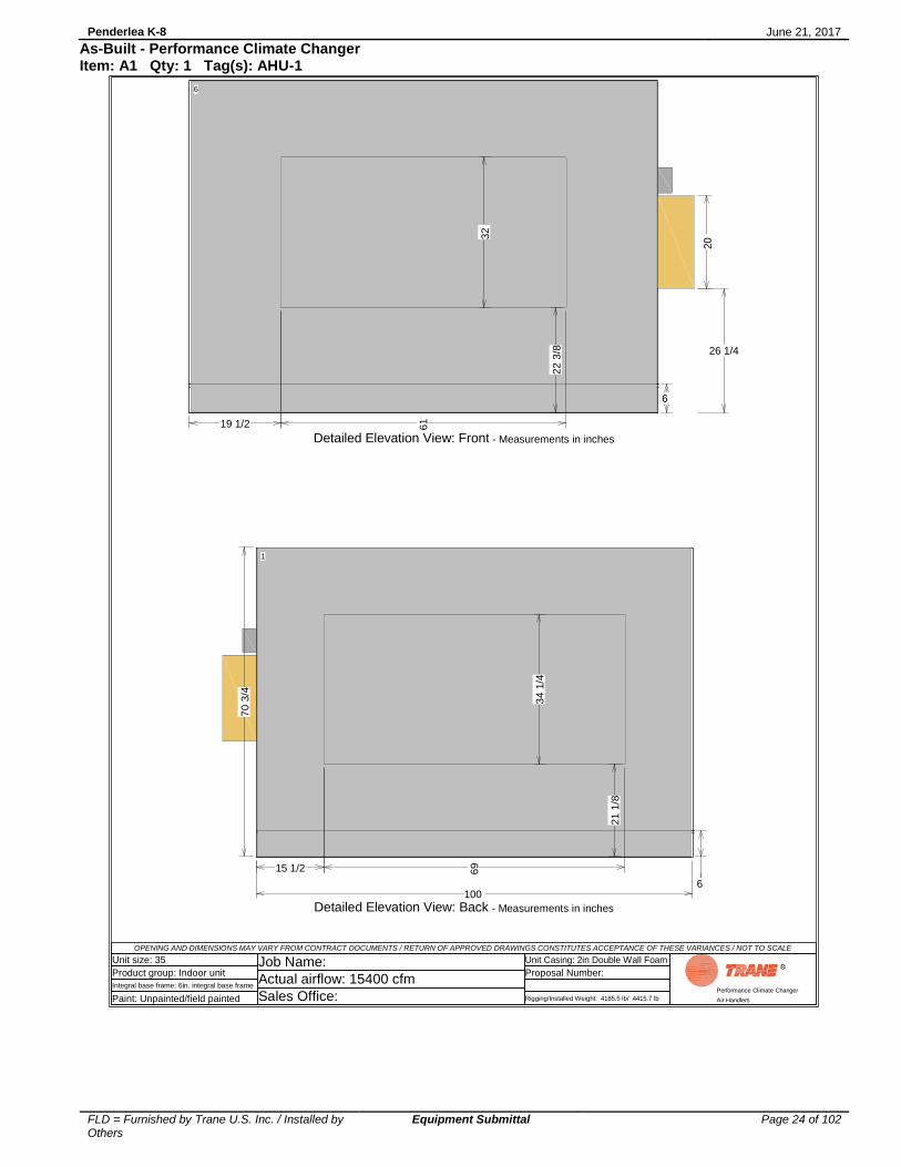
Penderlea K-8 June 21, 2017
FLD = Furnished by Trane U.S. Inc. / Installed by Others
Equipment Submittal Page 24 of 102
As-Built - Performance Climate Changer Item: A1 Qty: 1 Tag(s): AHU-1
OPENING AND DIMENSIONS MAY VARY FROM CONTRACT DOCUMENTS / RETURN OF APPROVED DRAWINGS CONSTITUTES ACCEPTANCE OF THESE VARIANCES / NOT TO SCALE
Unit size: 35
Product group: Indoor unit
Integral base frame: 6in. integral base frame
Paint: Unpainted/field painted
Job Name:
Actual airflow: 15400 cfm
Sales Office:
Unit Casing: 2in Double Wall Foam
Proposal Number:
Rigging/Installed Weight: 4185.5 lb/ 4415.7 lb
Performance Climate Changer
Air Handlers
1
69
34 1
/4
15 1/2
100 6
21 1
/8
70 3
/4
Detailed Elevation View: Back - Measurements in inches
6
61
32
20
19 1/2
6
22 3
/8 26 1/4
Detailed Elevation View: Front - Measurements in inches

Penderlea K-8 June 21, 2017
FLD = Furnished by Trane U.S. Inc. / Installed by Others
Equipment Submittal Page 25 of 102
As-Built - Performance Climate Changer Item: A1 Qty: 1 Tag(s): AHU-1
OP
EN
ING
AN
D D
IME
NS
ION
S M
AY
VA
RY
FR
OM
CO
NT
RA
CT
DO
CU
ME
NT
S / R
ET
UR
N O
F A
PP
RO
VE
D D
RA
WIN
GS
CO
NS
TIT
UT
ES
AC
CE
PT
AN
CE
OF
TH
ES
E V
AR
IAN
CE
S / N
OT
TO
SC
AL
E
Unit s
ize
: 3
5
Pro
du
ct g
rou
p: In
do
or
unit
Inte
gra
l b
ase
fra
me
: 6
in. in
teg
ral b
ase
fra
me
Pa
int: U
np
ain
ted
/fie
ld p
ain
ted
Jo
b N
am
e:
Actu
al a
irflo
w: 1
54
00
cfm
Sa
les O
ffic
e:
Un
it C
asin
g: 2in
Do
ub
le W
all
Fo
am
Pro
po
sa
l N
um
be
r:
Rig
gin
g/In
sta
lled
We
igh
t: 4
18
5.5
lb
/ 4
41
5.7
lb
Perform
ance C
limate
Changer
Air H
andle
rs
33 1
/836 1
/239 5
/840 5
/8
70 3/4
63
52
41
7 1
/4
5 1
/2
15 5
/8
10
1/4
56 1
/214
19 1
/810
19 1
/848
1.5
" (N
PT
E)
Retu
rn
1.5
" (N
PT
E)
Supply
3/8
" (N
PT
I) V
ent
3/8
" d
rain
(N
PT
I)
2.5
" (N
PT
E)
Retu
rn
2.5
" (N
PT
E)
Supply
3/8
" (N
PT
I) V
ent
3/8
" dra
in (
NP
TI)
166 5
/8
Coil
co
nnection v
iew
: R
ight
- M
easu
rem
ents
in inch
es
NP
TI
: N
ati
on
al
Pip
e T
hre
ad
In
tern
al
Co
nn
ecti
on
NP
TE
: N
ati
on
al
Pip
e T
hre
ad
Exte
rna
l C
on
ne
cti
on

Penderlea K-8 June 21, 2017
FLD = Furnished by Trane U.S. Inc. / Installed by Others
Equipment Submittal Page 26 of 102
As-Built - Performance Climate Changer Item: A1 Qty: 1 Tag(s): AHU-1
OP
EN
ING
AN
D D
IME
NS
ION
S M
AY
VA
RY
FR
OM
CO
NT
RA
CT
DO
CU
ME
NT
S / R
ET
UR
N O
F A
PP
RO
VE
D D
RA
WIN
GS
CO
NS
TIT
UT
ES
AC
CE
PT
AN
CE
OF
TH
ES
E V
AR
IAN
CE
S / N
OT
TO
SC
AL
E
Unit s
ize
: 3
5
Pro
du
ct g
rou
p: In
do
or
unit
Inte
gra
l b
ase
fra
me
: 6
in. in
teg
ral b
ase
fra
me
Pa
int: U
np
ain
ted
/fie
ld p
ain
ted
Jo
b N
am
e:
Actu
al a
irflo
w: 1
54
00
cfm
Sa
les O
ffic
e:
Un
it C
asin
g: 2in
Do
ub
le W
all
Fo
am
Pro
po
sa
l N
um
be
r:
Rig
gin
g/In
sta
lled
We
igh
t: 4
18
5.5
lb
/ 4
41
5.7
lb
Perform
ance C
limate
Changer
Air H
andle
rs
63
52
41
56 1
/214
19
1/8
10
19 1
/848
70 3/4
16
6 5
/8C
oil
co
nnection v
iew
: Left
- M
easu
rem
ents
in inch
es
NP
TI
: N
ati
on
al
Pip
e T
hre
ad
In
tern
al
Co
nn
ecti
on
NP
TE
: N
ati
on
al
Pip
e T
hre
ad
Exte
rna
l C
on
ne
cti
on

Penderlea K-8 June 21, 2017
FLD = Furnished by Trane U.S. Inc. / Installed by Others
Equipment Submittal Page 27 of 102
As-Built - Performance Climate Changer Item: A2 Qty: 1 Tag(s): AHU-2
OP
EN
ING
AN
D D
IME
NS
ION
S M
AY
VA
RY
FR
OM
CO
NT
RA
CT
DO
CU
ME
NT
S / R
ET
UR
N O
F A
PP
RO
VE
D D
RA
WIN
GS
CO
NS
TIT
UT
ES
AC
CE
PT
AN
CE
OF
TH
ES
E V
AR
IAN
CE
S / N
OT
TO
SC
AL
E
Unit s
ize
: 3
5
Pro
du
ct g
rou
p: In
do
or
unit
Inte
gra
l b
ase
fra
me
: 6
in. in
teg
ral b
ase
fra
me
Pa
int: U
np
ain
ted
/fie
ld p
ain
ted
Jo
b N
am
e:
Actu
al a
irflo
w: 1
60
00
cfm
Sa
les O
ffic
e:
Un
it C
asin
g: 2in
Do
ub
le W
all
Fo
am
Pro
po
sa
l N
um
be
r:
Rig
gin
g/In
sta
lled
We
igh
t: 4
19
4.3
lb
/ 4
42
4.5
lb
Perform
ance C
limate
Changer
Air H
andle
rs
22"
10"
15"
20"
15 1
/2
69
19 1
/2
61
7 7
/83
1/4
100
12
34
56
78
6 2
1 1
/8
34 1
/4
22 3
/8
32
46 3
/4
5 1
/2
34 1
/220 1
/8
78 5
/82 3
/4
6 1
/23
4 1
/4
1.2
5"
N.P
.T.E
10
11
75 5
/8S
hip
Sp
lit1875
lb
s
91 1
/8S
hip
Split
248
5 lbs
166 5
/8
70 3
/4
1 2 3 4 5 6 7 8 9 10
11
Op
enin
g f
ront
32.0
00 x
61.0
00
Ple
num
fan -
22
.25
in.
dd
ple
num
, 8
0%
wid
th,
Mpre
ss S
upp
ly f
an 1
0 h
p460/3
Overl
oad b
ox R
HU
V lig
ht
sw
itch R
HC
oolin
g c
oil
- 6
Coil
type
UW
Heating
coil
- 1
C
oil
type
5W
Dam
per
top-p
ara
llel b
lade
34.2
50 x
69.0
00
Dam
per
back-p
ara
llel
bla
de
34.2
50 x
69.0
00
1.2
5"
N.P
.T.E
UV
lig
ht
rack
Angle
d f
ilters
-
Doors
22 w
idth
x 6
1 h
eig
ht
15 w
idth
x 6
1 h
eig
ht
10 w
idth
x 6
1 h
eig
ht
20 w
idth
x 6
1 h
eig
ht
Fo
r m
an
eu
veri
ng
pu
rpo
ses,
inclu
de 1
.125 i
nch
es t
o e
ach
sh
ip s
pli
t le
ng
th f
or
overl
ap
pin
g p
an
el
flan
ge.
Fla
ng
e w
ill
no
t ad
d t
o o
vera
ll i
nsta
lled
un
it l
en
gth
sh
ow
n.

Penderlea K-8 June 21, 2017
FLD = Furnished by Trane U.S. Inc. / Installed by Others
Equipment Submittal Page 28 of 102
As-Built - Performance Climate Changer Item: A2 Qty: 1 Tag(s): AHU-2
OPENING AND DIMENSIONS MAY VARY FROM CONTRACT DOCUMENTS / RETURN OF APPROVED DRAWINGS CONSTITUTES ACCEPTANCE OF THESE VARIANCES / NOT TO SCALE
Unit size: 35
Product group: Indoor unit
Integral base frame: 6in. integral base frame
Paint: Unpainted/field painted
Job Name:
Actual airflow: 16000 cfm
Sales Office:
Unit Casing: 2in Double Wall Foam
Proposal Number:
Rigging/Installed Weight: 4194.3 lb/ 4424.5 lb
Performance Climate Changer
Air Handlers
Pos #635241
ModuleFan sectionAccess sectionAccess sectionCoil sectionCoil sectionAir mixing section
Length56 1/214 19 1/810 19 1/848
Weight1606.65246.42301.80399.86981.80887.97
Installed Unit Weight 4424.51 lbs
6 35 24 1
100
Basic Overall Plan View: Top - Measurements in inches
S2 S1
6
6 35 24 1
166 5/8
70
3/4
Overall Elevation View: Right - Shipping splits indicated by bold outline. - Measurements in inches
For maneuvering purposes, include 1.125 inches to each ship split length for overlapping panel flange. Flange will not add to overall installed unit length shown.

Penderlea K-8 June 21, 2017
FLD = Furnished by Trane U.S. Inc. / Installed by Others
Equipment Submittal Page 29 of 102
As-Built - Performance Climate Changer Item: A2 Qty: 1 Tag(s): AHU-2
OPENING AND DIMENSIONS MAY VARY FROM CONTRACT DOCUMENTS / RETURN OF APPROVED DRAWINGS CONSTITUTES ACCEPTANCE OF THESE VARIANCES / NOT TO SCALE
Unit size: 35
Product group: Indoor unit
Integral base frame: 6in. integral base frame
Paint: Unpainted/field painted
Job Name:
Actual airflow: 16000 cfm
Sales Office:
Unit Casing: 2in Double Wall Foam
Proposal Number:
Rigging/Installed Weight: 4194.3 lb/ 4424.5 lb
Performance Climate Changer
Air Handlers
6 35 24 1
43
34 1/2
3
3
7 1/4
20
1/8
2 3
/4
34 1
/4
56 1/2
14
19 1/8 10 19 1/8
48
1.378 dia elec con(NEMA)
1.378 dia. elec. conn.(UV lts)
3 5
/8
7 7/8
3 1/4 15 1
/2
8 5
7 7
/8
69
100
Right Side of Unit Detailed Plan View: Top - Measurements in inches
6 35 24 1
56 1/2 14 19 1/8 10 19 1/8 48
Left Side of Unit Detailed Plan View: Bottom - Measurements in inches

Penderlea K-8 June 21, 2017
FLD = Furnished by Trane U.S. Inc. / Installed by Others
Equipment Submittal Page 30 of 102
As-Built - Performance Climate Changer Item: A2 Qty: 1 Tag(s): AHU-2
OPENING AND DIMENSIONS MAY VARY FROM CONTRACT DOCUMENTS / RETURN OF APPROVED DRAWINGS CONSTITUTES ACCEPTANCE OF THESE VARIANCES / NOT TO SCALE
Unit size: 35
Product group: Indoor unit
Integral base frame: 6in. integral base frame
Paint: Unpainted/field painted
Job Name:
Actual airflow: 16000 cfm
Sales Office:
Unit Casing: 2in Double Wall Foam
Proposal Number:
Rigging/Installed Weight: 4194.3 lb/ 4424.5 lb
Performance Climate Changer
Air Handlers
63 52 41
56 1/214 19 1/810 19 1/848
6
70
3/4
Detailed Elevation View: Left - Measurements in inches
6 6 7/8 7 3/4
21 1/822 3/826 1/4
46 3/4
32
20
60
1/2
5 1
/2
34 1
/4
6 35 24 1
34 1/2
2 1/2
2 1/82 1/8 3
9 3/8
2 1/8
7 1/4
20 1
/822" 10"15"
2 3
/4
20"
34
1/4
1.25" N.P.T.E
166 5/8
70 3
/4
Detailed Elevation View: Right - Measurements in inches

Penderlea K-8 June 21, 2017
FLD = Furnished by Trane U.S. Inc. / Installed by Others
Equipment Submittal Page 31 of 102
As-Built - Performance Climate Changer Item: A2 Qty: 1 Tag(s): AHU-2
OPENING AND DIMENSIONS MAY VARY FROM CONTRACT DOCUMENTS / RETURN OF APPROVED DRAWINGS CONSTITUTES ACCEPTANCE OF THESE VARIANCES / NOT TO SCALE
Unit size: 35
Product group: Indoor unit
Integral base frame: 6in. integral base frame
Paint: Unpainted/field painted
Job Name:
Actual airflow: 16000 cfm
Sales Office:
Unit Casing: 2in Double Wall Foam
Proposal Number:
Rigging/Installed Weight: 4194.3 lb/ 4424.5 lb
Performance Climate Changer
Air Handlers
1
69
34 1
/4
15 1/2
100 6
21 1
/8
70 3
/4
Detailed Elevation View: Back - Measurements in inches
6
61
32
20
19 1/2
6
22 3
/8 26 1/4
Detailed Elevation View: Front - Measurements in inches

Penderlea K-8 June 21, 2017
FLD = Furnished by Trane U.S. Inc. / Installed by Others
Equipment Submittal Page 32 of 102
As-Built - Performance Climate Changer Item: A2 Qty: 1 Tag(s): AHU-2
OP
EN
ING
AN
D D
IME
NS
ION
S M
AY
VA
RY
FR
OM
CO
NT
RA
CT
DO
CU
ME
NT
S / R
ET
UR
N O
F A
PP
RO
VE
D D
RA
WIN
GS
CO
NS
TIT
UT
ES
AC
CE
PT
AN
CE
OF
TH
ES
E V
AR
IAN
CE
S / N
OT
TO
SC
AL
E
Unit s
ize
: 3
5
Pro
du
ct g
rou
p: In
do
or
unit
Inte
gra
l b
ase
fra
me
: 6
in. in
teg
ral b
ase
fra
me
Pa
int: U
np
ain
ted
/fie
ld p
ain
ted
Jo
b N
am
e:
Actu
al a
irflo
w: 1
60
00
cfm
Sa
les O
ffic
e:
Un
it C
asin
g: 2in
Do
ub
le W
all
Fo
am
Pro
po
sa
l N
um
be
r:
Rig
gin
g/In
sta
lled
We
igh
t: 4
19
4.3
lb
/ 4
42
4.5
lb
Perform
ance C
limate
Changer
Air H
andle
rs
33 1
/836 1
/239 5
/840 5
/8
70 3/4
63
52
41
7 1
/4
5 1
/2
15 5
/8
10
1/4
56 1
/214
19 1
/810
19 1
/848
1.5
" (N
PT
E)
Retu
rn
1.5
" (N
PT
E)
Supply
3/8
" (N
PT
I) V
ent
3/8
" d
rain
(N
PT
I)
2.5
" (N
PT
E)
Retu
rn
2.5
" (N
PT
E)
Supply
3/8
" (N
PT
I) V
ent
3/8
" dra
in (
NP
TI)
166 5
/8
Coil
co
nnection v
iew
: R
ight
- M
easu
rem
ents
in inch
es
NP
TI
: N
ati
on
al
Pip
e T
hre
ad
In
tern
al
Co
nn
ecti
on
NP
TE
: N
ati
on
al
Pip
e T
hre
ad
Exte
rna
l C
on
ne
cti
on

Penderlea K-8 June 21, 2017
FLD = Furnished by Trane U.S. Inc. / Installed by Others
Equipment Submittal Page 33 of 102
As-Built - Performance Climate Changer Item: A2 Qty: 1 Tag(s): AHU-2
OP
EN
ING
AN
D D
IME
NS
ION
S M
AY
VA
RY
FR
OM
CO
NT
RA
CT
DO
CU
ME
NT
S / R
ET
UR
N O
F A
PP
RO
VE
D D
RA
WIN
GS
CO
NS
TIT
UT
ES
AC
CE
PT
AN
CE
OF
TH
ES
E V
AR
IAN
CE
S / N
OT
TO
SC
AL
E
Unit s
ize
: 3
5
Pro
du
ct g
rou
p: In
do
or
unit
Inte
gra
l b
ase
fra
me
: 6
in. in
teg
ral b
ase
fra
me
Pa
int: U
np
ain
ted
/fie
ld p
ain
ted
Jo
b N
am
e:
Actu
al a
irflo
w: 1
60
00
cfm
Sa
les O
ffic
e:
Un
it C
asin
g: 2in
Do
ub
le W
all
Fo
am
Pro
po
sa
l N
um
be
r:
Rig
gin
g/In
sta
lled
We
igh
t: 4
19
4.3
lb
/ 4
42
4.5
lb
Perform
ance C
limate
Changer
Air H
andle
rs
63
52
41
56 1
/214
19
1/8
10
19 1
/848
70 3/4
16
6 5
/8C
oil
co
nnection v
iew
: Left
- M
easu
rem
ents
in inch
es
NP
TI
: N
ati
on
al
Pip
e T
hre
ad
In
tern
al
Co
nn
ecti
on
NP
TE
: N
ati
on
al
Pip
e T
hre
ad
Exte
rna
l C
on
ne
cti
on

Penderlea K-8 June 21, 2017
FLD = Furnished by Trane U.S. Inc. / Installed by Others
Equipment Submittal Page 34 of 102
As-Built - Performance Climate Changer Item: A3 Qty: 1 Tag(s): AHU-3
OP
EN
ING
AN
D D
IME
NS
ION
S M
AY
VA
RY
FR
OM
CO
NT
RA
CT
DO
CU
ME
NT
S / R
ET
UR
N O
F A
PP
RO
VE
D D
RA
WIN
GS
CO
NS
TIT
UT
ES
AC
CE
PT
AN
CE
OF
TH
ES
E V
AR
IAN
CE
S / N
OT
TO
SC
AL
E
Unit s
ize
: 3
5
Pro
du
ct g
rou
p: In
do
or
unit
Inte
gra
l b
ase
fra
me
: 6
in. in
teg
ral b
ase
fra
me
Pa
int: U
np
ain
ted
/fie
ld p
ain
ted
Jo
b N
am
e:
Actu
al a
irflo
w: 1
72
00
cfm
Sa
les O
ffic
e:
Un
it C
asin
g: 2in
Do
ub
le W
all
Fo
am
Pro
po
sa
l N
um
be
r:
Rig
gin
g/In
sta
lled
We
igh
t: 4
44
2.9
lb
/ 4
72
8.6
lb
Perform
ance C
limate
Changer
Air H
andle
rs
22"
10
"15"
20"
15 1
/2
69
19 1
/2
61 7 7
/8
3 1
/4
100
12
3
4
56
78
6 2
1 1
/8
34 1
/4
22 3
/8
32
6 1
/234 1
/4
91
0
75 5
/8S
hip
Sp
lit204
7 lb
s
91
1/8
Ship
Split
26
17 lbs
166 5
/8
70 3
/4
1 2 3 4 5 6 7 8 9 10
Openin
g f
ront
32
.000
x 6
1.0
00
Ple
nu
m f
an
- 2
2.2
5in
. dd
ple
num
, fu
ll w
idth
, M
pre
ss
Supply
fan 1
2.5
hp 4
60/3
UV
lig
ht
sw
itch L
HO
ve
rload b
ox L
HC
oo
ling
coil
- 8
C
oil
type
UW
Hea
tin
g c
oil
- 1
Coil
type
5W
Dam
per
top-p
ara
llel bla
de
34
.250
x 6
9.0
00
Dam
per
back-p
ara
llel
bla
de
34
.250
x 6
9.0
00
UV
lig
ht
rack
Angle
d f
ilters
-
Doo
rs22
wid
th x
61 h
eig
ht
15
wid
th x
61 h
eig
ht
10
wid
th x
61 h
eig
ht
20
wid
th x
61 h
eig
ht
Fo
r m
an
eu
veri
ng
pu
rpo
ses,
inclu
de 1
.125 i
nch
es t
o e
ach
sh
ip s
pli
t le
ng
th f
or
overl
ap
pin
g p
an
el
flan
ge.
Fla
ng
e w
ill
no
t ad
d t
o o
vera
ll i
nsta
lled
un
it l
en
gth
sh
ow
n.
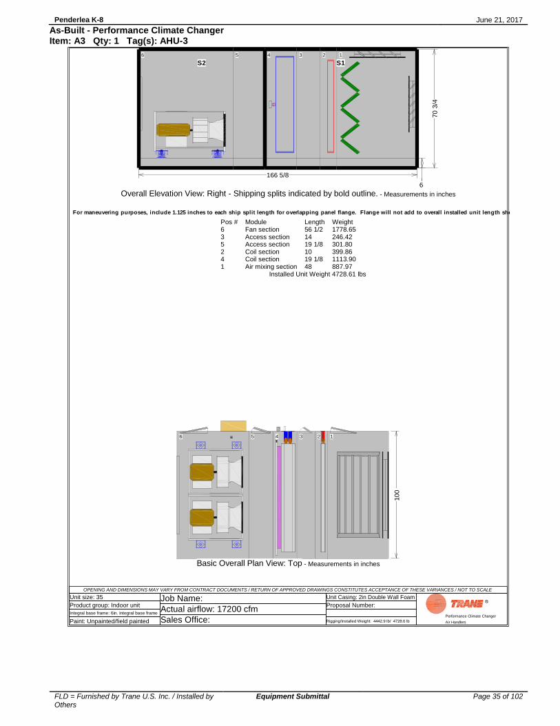
Penderlea K-8 June 21, 2017
FLD = Furnished by Trane U.S. Inc. / Installed by Others
Equipment Submittal Page 35 of 102
As-Built - Performance Climate Changer Item: A3 Qty: 1 Tag(s): AHU-3
OPENING AND DIMENSIONS MAY VARY FROM CONTRACT DOCUMENTS / RETURN OF APPROVED DRAWINGS CONSTITUTES ACCEPTANCE OF THESE VARIANCES / NOT TO SCALE
Unit size: 35
Product group: Indoor unit
Integral base frame: 6in. integral base frame
Paint: Unpainted/field painted
Job Name:
Actual airflow: 17200 cfm
Sales Office:
Unit Casing: 2in Double Wall Foam
Proposal Number:
Rigging/Installed Weight: 4442.9 lb/ 4728.6 lb
Performance Climate Changer
Air Handlers
Pos #635241
ModuleFan sectionAccess sectionAccess sectionCoil sectionCoil sectionAir mixing section
Length56 1/214 19 1/810 19 1/848
Weight1778.65246.42301.80399.861113.90887.97
Installed Unit Weight 4728.61 lbs
6 35 24 1
100
Basic Overall Plan View: Top - Measurements in inches
S2 S1
6
6 35 24 1
166 5/8
70
3/4
Overall Elevation View: Right - Shipping splits indicated by bold outline. - Measurements in inches
For maneuvering purposes, include 1.125 inches to each ship split length for overlapping panel flange. Flange will not add to overall installed unit length shown.

Penderlea K-8 June 21, 2017
FLD = Furnished by Trane U.S. Inc. / Installed by Others
Equipment Submittal Page 36 of 102
As-Built - Performance Climate Changer Item: A3 Qty: 1 Tag(s): AHU-3
OPENING AND DIMENSIONS MAY VARY FROM CONTRACT DOCUMENTS / RETURN OF APPROVED DRAWINGS CONSTITUTES ACCEPTANCE OF THESE VARIANCES / NOT TO SCALE
Unit size: 35
Product group: Indoor unit
Integral base frame: 6in. integral base frame
Paint: Unpainted/field painted
Job Name:
Actual airflow: 17200 cfm
Sales Office:
Unit Casing: 2in Double Wall Foam
Proposal Number:
Rigging/Installed Weight: 4442.9 lb/ 4728.6 lb
Performance Climate Changer
Air Handlers
6 35 24 1
43 3 7 1/4
34
1/4
56 1/2
14
19 1/8 10 19 1/8 48
1.378 dia elec con(NEMA)
1.378 dia. elec. conn.(UV lts)
15 1
/2
92 95
69
100
Right Side of Unit Detailed Plan View: Top - Measurements in inches
6 35 24 1
56 1/2 14 19 1/8 10 19 1/8 48
Left Side of Unit Detailed Plan View: Bottom - Measurements in inches
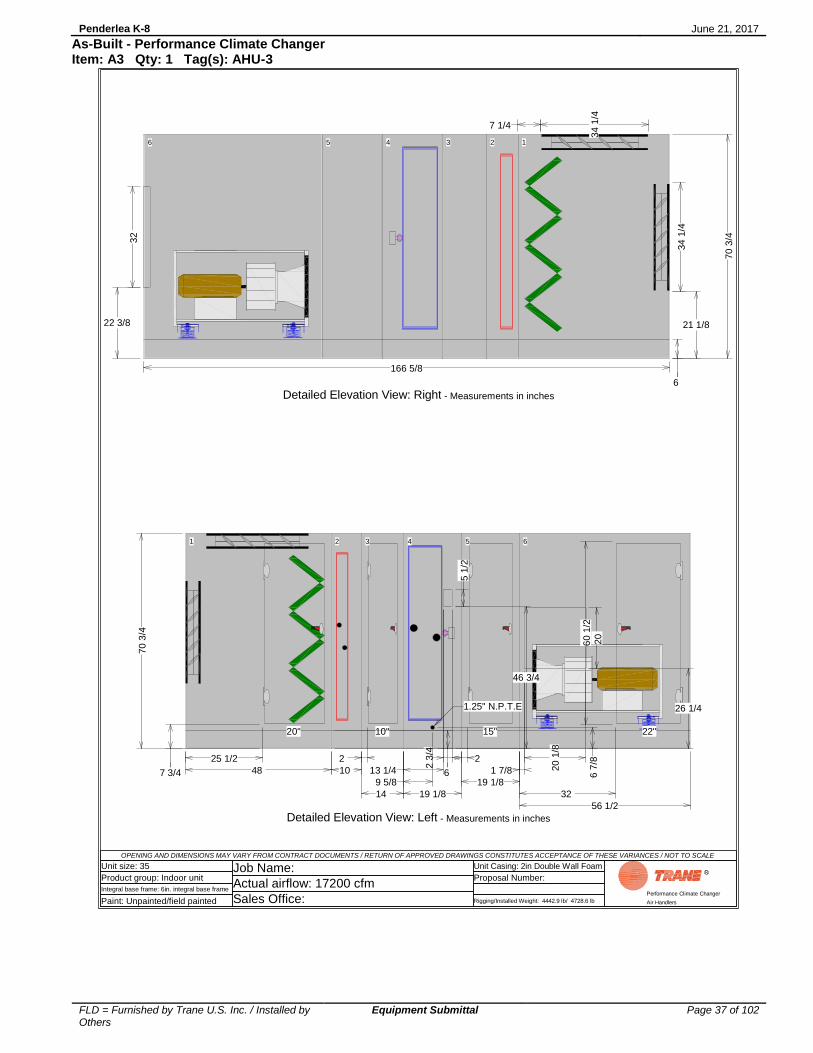
Penderlea K-8 June 21, 2017
FLD = Furnished by Trane U.S. Inc. / Installed by Others
Equipment Submittal Page 37 of 102
As-Built - Performance Climate Changer Item: A3 Qty: 1 Tag(s): AHU-3
OPENING AND DIMENSIONS MAY VARY FROM CONTRACT DOCUMENTS / RETURN OF APPROVED DRAWINGS CONSTITUTES ACCEPTANCE OF THESE VARIANCES / NOT TO SCALE
Unit size: 35
Product group: Indoor unit
Integral base frame: 6in. integral base frame
Paint: Unpainted/field painted
Job Name:
Actual airflow: 17200 cfm
Sales Office:
Unit Casing: 2in Double Wall Foam
Proposal Number:
Rigging/Installed Weight: 4442.9 lb/ 4728.6 lb
Performance Climate Changer
Air Handlers
63 52 41
20 1
/8
22"10" 15"
2 3
/4
20"
20
60 1
/2
5 1
/2
1 7/8
32
2 2
13 1/4
9 5/8
25 1/2
56 1/2
14
19 1/8
10
19 1/8
48
1.25" N.P.T.E
6 6 7
/8
7 3/4
26 1/4
46 3/4
70 3
/4
Detailed Elevation View: Left - Measurements in inches
6
21 1/822 3/8
32
34 1
/4
6 35 24 1
7 1/4
34 1
/4
166 5/8
70 3
/4
Detailed Elevation View: Right - Measurements in inches
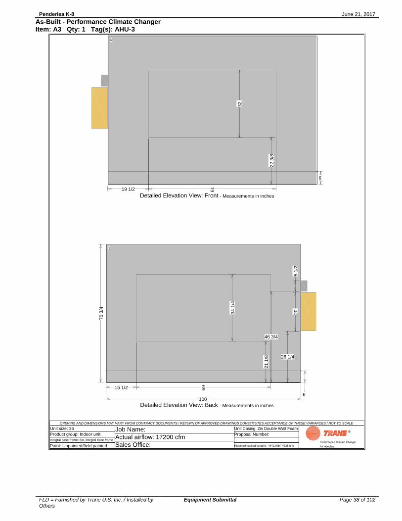
Penderlea K-8 June 21, 2017
FLD = Furnished by Trane U.S. Inc. / Installed by Others
Equipment Submittal Page 38 of 102
As-Built - Performance Climate Changer Item: A3 Qty: 1 Tag(s): AHU-3
OPENING AND DIMENSIONS MAY VARY FROM CONTRACT DOCUMENTS / RETURN OF APPROVED DRAWINGS CONSTITUTES ACCEPTANCE OF THESE VARIANCES / NOT TO SCALE
Unit size: 35
Product group: Indoor unit
Integral base frame: 6in. integral base frame
Paint: Unpainted/field painted
Job Name:
Actual airflow: 17200 cfm
Sales Office:
Unit Casing: 2in Double Wall Foam
Proposal Number:
Rigging/Installed Weight: 4442.9 lb/ 4728.6 lb
Performance Climate Changer
Air Handlers
1
69
20
5 1
/2
34
1/4
15 1/2
100 6
21 1
/8 26 1/4
46 3/4
70 3
/4
Detailed Elevation View: Back - Measurements in inches
6
61
32
19 1/2
6
22 3
/8
Detailed Elevation View: Front - Measurements in inches
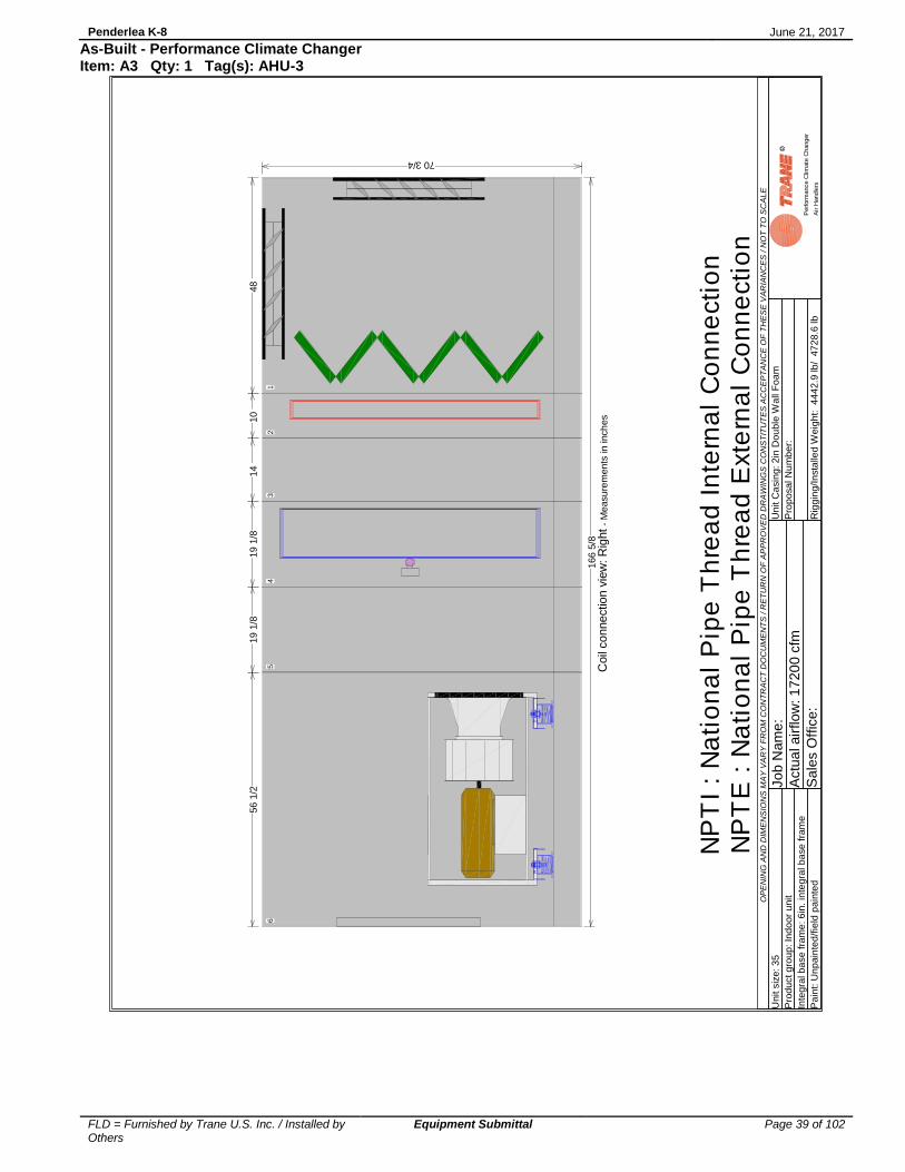
Penderlea K-8 June 21, 2017
FLD = Furnished by Trane U.S. Inc. / Installed by Others
Equipment Submittal Page 39 of 102
As-Built - Performance Climate Changer Item: A3 Qty: 1 Tag(s): AHU-3
OP
EN
ING
AN
D D
IME
NS
ION
S M
AY
VA
RY
FR
OM
CO
NT
RA
CT
DO
CU
ME
NT
S / R
ET
UR
N O
F A
PP
RO
VE
D D
RA
WIN
GS
CO
NS
TIT
UT
ES
AC
CE
PT
AN
CE
OF
TH
ES
E V
AR
IAN
CE
S / N
OT
TO
SC
AL
E
Unit s
ize
: 3
5
Pro
du
ct g
rou
p: In
do
or
unit
Inte
gra
l b
ase
fra
me
: 6
in. in
teg
ral b
ase
fra
me
Pa
int: U
np
ain
ted
/fie
ld p
ain
ted
Jo
b N
am
e:
Actu
al a
irflo
w: 1
72
00
cfm
Sa
les O
ffic
e:
Un
it C
asin
g: 2in
Do
ub
le W
all
Fo
am
Pro
po
sa
l N
um
be
r:
Rig
gin
g/In
sta
lled
We
igh
t: 4
44
2.9
lb
/ 4
72
8.6
lb
Perform
ance C
limate
Changer
Air H
andle
rs
70 3/4
63
52
41
56 1
/214
19 1
/810
19 1
/848
166 5
/8C
oil
co
nnection v
iew
: R
ight
- M
easu
rem
ents
in inch
es
NP
TI
: N
ati
on
al
Pip
e T
hre
ad
In
tern
al
Co
nn
ecti
on
NP
TE
: N
ati
on
al
Pip
e T
hre
ad
Exte
rna
l C
on
ne
cti
on

Penderlea K-8 June 21, 2017
FLD = Furnished by Trane U.S. Inc. / Installed by Others
Equipment Submittal Page 40 of 102
As-Built - Performance Climate Changer Item: A3 Qty: 1 Tag(s): AHU-3
OP
EN
ING
AN
D D
IME
NS
ION
S M
AY
VA
RY
FR
OM
CO
NT
RA
CT
DO
CU
ME
NT
S / R
ET
UR
N O
F A
PP
RO
VE
D D
RA
WIN
GS
CO
NS
TIT
UT
ES
AC
CE
PT
AN
CE
OF
TH
ES
E V
AR
IAN
CE
S / N
OT
TO
SC
AL
E
Unit s
ize
: 3
5
Pro
du
ct g
rou
p: In
do
or
unit
Inte
gra
l b
ase
fra
me
: 6
in. in
teg
ral b
ase
fra
me
Pa
int: U
np
ain
ted
/fie
ld p
ain
ted
Jo
b N
am
e:
Actu
al a
irflo
w: 1
72
00
cfm
Sa
les O
ffic
e:
Un
it C
asin
g: 2in
Do
ub
le W
all
Fo
am
Pro
po
sa
l N
um
be
r:
Rig
gin
g/In
sta
lled
We
igh
t: 4
44
2.9
lb
/ 4
72
8.6
lb
Perform
ance C
limate
Changer
Air H
andle
rs
63
52
41
2 3
/4
4 1
/2
3 3
/8
10 7
/8
56 1
/214
19
1/8
10
19 1
/848
1.5
" (N
PT
E)
Retu
rn
1.5
" (N
PT
E)
Supply
3/8
" (N
PT
I) V
ent
3/8
" dra
in (
NP
TI)
2.5
" (N
PT
E)
Re
turn
2.5
" (N
PT
E)
Supp
ly
3/8
" (N
PT
I) V
ent
3/8
" d
rain
(N
PT
I)
33 1
/836 1
/239 5
/840 5
/8
70 3/4
16
6 5
/8
Coil
co
nnection v
iew
: Left
- M
easu
rem
ents
in inch
es
NP
TI
: N
ati
on
al
Pip
e T
hre
ad
In
tern
al
Co
nn
ecti
on
NP
TE
: N
ati
on
al
Pip
e T
hre
ad
Exte
rna
l C
on
ne
cti
on

Penderlea K-8 June 21, 2017
FLD = Furnished by Trane U.S. Inc. / Installed by Others
Equipment Submittal Page 41 of 102
As-Built - Performance Climate Changer Item: A4 Qty: 1 Tag(s): AHU-4
OP
EN
ING
AN
D D
IME
NS
ION
S M
AY
VA
RY
FR
OM
CO
NT
RA
CT
DO
CU
ME
NT
S / R
ET
UR
N O
F A
PP
RO
VE
D D
RA
WIN
GS
CO
NS
TIT
UT
ES
AC
CE
PT
AN
CE
OF
TH
ES
E V
AR
IAN
CE
S / N
OT
TO
SC
AL
E
Unit s
ize
: 3
5
Pro
du
ct g
rou
p: In
do
or
unit
Inte
gra
l b
ase
fra
me
: 6
in. in
teg
ral b
ase
fra
me
Pa
int: U
np
ain
ted
/fie
ld p
ain
ted
Jo
b N
am
e:
Actu
al a
irflo
w: 1
65
00
cfm
Sa
les O
ffic
e:
Un
it C
asin
g: 2in
Do
ub
le W
all
Fo
am
Pro
po
sa
l N
um
be
r:
Rig
gin
g/In
sta
lled
We
igh
t: 4
46
6.4
lb
/ 4
75
2.1
lb
Perform
ance C
limate
Changer
Air H
andle
rs
22"
10
"15"
20"
15 1
/2
69
19 1
/2
61 7 7
/8
3 1
/4
100
12
3
4
56
78
6 2
1 1
/8
34 1
/4
22 3
/8
32
6 1
/234 1
/4
91
0
75 5
/8S
hip
Sp
lit204
7 lb
s
91
1/8
Ship
Split
26
41 lbs
166 5
/8
70 3
/4
1 2 3 4 5 6 7 8 9 10
Openin
g f
ront
32
.000
x 6
1.0
00
Ple
nu
m f
an
- 2
2.2
5in
. dd
ple
num
, fu
ll w
idth
, M
pre
ss
Supply
fan 1
2.5
hp 4
60/3
UV
lig
ht
sw
itch L
HO
ve
rload b
ox L
HC
oo
ling
coil
- 8
C
oil
type
UW
Hea
tin
g c
oil
- 1
Coil
type
5W
Dam
per
top-p
ara
llel bla
de
34
.250
x 6
9.0
00
Dam
per
back-p
ara
llel
bla
de
34
.250
x 6
9.0
00
UV
lig
ht
rack
Angle
d f
ilters
-
Doo
rs22
wid
th x
61 h
eig
ht
15
wid
th x
61 h
eig
ht
10
wid
th x
61 h
eig
ht
20
wid
th x
61 h
eig
ht
Fo
r m
an
eu
veri
ng
pu
rpo
ses,
inclu
de 1
.125 i
nch
es t
o e
ach
sh
ip s
pli
t le
ng
th f
or
overl
ap
pin
g p
an
el
flan
ge.
Fla
ng
e w
ill
no
t ad
d t
o o
vera
ll i
nsta
lled
un
it l
en
gth
sh
ow
n.

Penderlea K-8 June 21, 2017
FLD = Furnished by Trane U.S. Inc. / Installed by Others
Equipment Submittal Page 42 of 102
As-Built - Performance Climate Changer Item: A4 Qty: 1 Tag(s): AHU-4
OPENING AND DIMENSIONS MAY VARY FROM CONTRACT DOCUMENTS / RETURN OF APPROVED DRAWINGS CONSTITUTES ACCEPTANCE OF THESE VARIANCES / NOT TO SCALE
Unit size: 35
Product group: Indoor unit
Integral base frame: 6in. integral base frame
Paint: Unpainted/field painted
Job Name:
Actual airflow: 16500 cfm
Sales Office:
Unit Casing: 2in Double Wall Foam
Proposal Number:
Rigging/Installed Weight: 4466.4 lb/ 4752.1 lb
Performance Climate Changer
Air Handlers
Pos #635241
ModuleFan sectionAccess sectionAccess sectionCoil sectionCoil sectionAir mixing section
Length56 1/214 19 1/810 19 1/848
Weight1778.65246.42301.80399.861137.40887.97
Installed Unit Weight 4752.11 lbs
6 35 24 1
100
Basic Overall Plan View: Top - Measurements in inches
S2 S1
6
6 35 24 1
166 5/8
70
3/4
Overall Elevation View: Right - Shipping splits indicated by bold outline. - Measurements in inches
For maneuvering purposes, include 1.125 inches to each ship split length for overlapping panel flange. Flange will not add to overall installed unit length shown.

Penderlea K-8 June 21, 2017
FLD = Furnished by Trane U.S. Inc. / Installed by Others
Equipment Submittal Page 43 of 102
As-Built - Performance Climate Changer Item: A4 Qty: 1 Tag(s): AHU-4
OPENING AND DIMENSIONS MAY VARY FROM CONTRACT DOCUMENTS / RETURN OF APPROVED DRAWINGS CONSTITUTES ACCEPTANCE OF THESE VARIANCES / NOT TO SCALE
Unit size: 35
Product group: Indoor unit
Integral base frame: 6in. integral base frame
Paint: Unpainted/field painted
Job Name:
Actual airflow: 16500 cfm
Sales Office:
Unit Casing: 2in Double Wall Foam
Proposal Number:
Rigging/Installed Weight: 4466.4 lb/ 4752.1 lb
Performance Climate Changer
Air Handlers
6 35 24 1
43 3 7 1/4
34
1/4
56 1/2
14
19 1/8 10 19 1/8 48
1.378 dia elec con(NEMA)
1.378 dia. elec. conn.(UV lts)
15 1
/2
92 95
69
100
Right Side of Unit Detailed Plan View: Top - Measurements in inches
6 35 24 1
56 1/2 14 19 1/8 10 19 1/8 48
Left Side of Unit Detailed Plan View: Bottom - Measurements in inches

Penderlea K-8 June 21, 2017
FLD = Furnished by Trane U.S. Inc. / Installed by Others
Equipment Submittal Page 44 of 102
As-Built - Performance Climate Changer Item: A4 Qty: 1 Tag(s): AHU-4
OPENING AND DIMENSIONS MAY VARY FROM CONTRACT DOCUMENTS / RETURN OF APPROVED DRAWINGS CONSTITUTES ACCEPTANCE OF THESE VARIANCES / NOT TO SCALE
Unit size: 35
Product group: Indoor unit
Integral base frame: 6in. integral base frame
Paint: Unpainted/field painted
Job Name:
Actual airflow: 16500 cfm
Sales Office:
Unit Casing: 2in Double Wall Foam
Proposal Number:
Rigging/Installed Weight: 4466.4 lb/ 4752.1 lb
Performance Climate Changer
Air Handlers
63 52 41
20 1
/8
22"10" 15"
2 3
/4
20"
20
60 1
/2
5 1
/2
1 7/8
32
2 2
13 1/4
9 5/8
25 1/2
56 1/2
14
19 1/8
10
19 1/8
48
1.25" N.P.T.E
6 6 7
/8
7 3/4
26 1/4
46 3/4
70 3
/4
Detailed Elevation View: Left - Measurements in inches
6
21 1/822 3/8
32
34 1
/4
6 35 24 1
7 1/4
34 1
/4
166 5/8
70 3
/4
Detailed Elevation View: Right - Measurements in inches

Penderlea K-8 June 21, 2017
FLD = Furnished by Trane U.S. Inc. / Installed by Others
Equipment Submittal Page 45 of 102
As-Built - Performance Climate Changer Item: A4 Qty: 1 Tag(s): AHU-4
OPENING AND DIMENSIONS MAY VARY FROM CONTRACT DOCUMENTS / RETURN OF APPROVED DRAWINGS CONSTITUTES ACCEPTANCE OF THESE VARIANCES / NOT TO SCALE
Unit size: 35
Product group: Indoor unit
Integral base frame: 6in. integral base frame
Paint: Unpainted/field painted
Job Name:
Actual airflow: 16500 cfm
Sales Office:
Unit Casing: 2in Double Wall Foam
Proposal Number:
Rigging/Installed Weight: 4466.4 lb/ 4752.1 lb
Performance Climate Changer
Air Handlers
1
69
20
5 1
/2
34
1/4
15 1/2
100 6
21 1
/8 26 1/4
46 3/4
70 3
/4
Detailed Elevation View: Back - Measurements in inches
6
61
32
19 1/2
6
22 3
/8
Detailed Elevation View: Front - Measurements in inches

Penderlea K-8 June 21, 2017
FLD = Furnished by Trane U.S. Inc. / Installed by Others
Equipment Submittal Page 46 of 102
As-Built - Performance Climate Changer Item: A4 Qty: 1 Tag(s): AHU-4
OP
EN
ING
AN
D D
IME
NS
ION
S M
AY
VA
RY
FR
OM
CO
NT
RA
CT
DO
CU
ME
NT
S / R
ET
UR
N O
F A
PP
RO
VE
D D
RA
WIN
GS
CO
NS
TIT
UT
ES
AC
CE
PT
AN
CE
OF
TH
ES
E V
AR
IAN
CE
S / N
OT
TO
SC
AL
E
Unit s
ize
: 3
5
Pro
du
ct g
rou
p: In
do
or
unit
Inte
gra
l b
ase
fra
me
: 6
in. in
teg
ral b
ase
fra
me
Pa
int: U
np
ain
ted
/fie
ld p
ain
ted
Jo
b N
am
e:
Actu
al a
irflo
w: 1
65
00
cfm
Sa
les O
ffic
e:
Un
it C
asin
g: 2in
Do
ub
le W
all
Fo
am
Pro
po
sa
l N
um
be
r:
Rig
gin
g/In
sta
lled
We
igh
t: 4
46
6.4
lb
/ 4
75
2.1
lb
Perform
ance C
limate
Changer
Air H
andle
rs
70 3/4
63
52
41
56 1
/214
19 1
/810
19 1
/848
166 5
/8C
oil
co
nnection v
iew
: R
ight
- M
easu
rem
ents
in inch
es
NP
TI
: N
ati
on
al
Pip
e T
hre
ad
In
tern
al
Co
nn
ecti
on
NP
TE
: N
ati
on
al
Pip
e T
hre
ad
Exte
rna
l C
on
ne
cti
on

Penderlea K-8 June 21, 2017
FLD = Furnished by Trane U.S. Inc. / Installed by Others
Equipment Submittal Page 47 of 102
As-Built - Performance Climate Changer Item: A4 Qty: 1 Tag(s): AHU-4
OP
EN
ING
AN
D D
IME
NS
ION
S M
AY
VA
RY
FR
OM
CO
NT
RA
CT
DO
CU
ME
NT
S / R
ET
UR
N O
F A
PP
RO
VE
D D
RA
WIN
GS
CO
NS
TIT
UT
ES
AC
CE
PT
AN
CE
OF
TH
ES
E V
AR
IAN
CE
S / N
OT
TO
SC
AL
E
Unit s
ize
: 3
5
Pro
du
ct g
rou
p: In
do
or
unit
Inte
gra
l b
ase
fra
me
: 6
in. in
teg
ral b
ase
fra
me
Pa
int: U
np
ain
ted
/fie
ld p
ain
ted
Jo
b N
am
e:
Actu
al a
irflo
w: 1
65
00
cfm
Sa
les O
ffic
e:
Un
it C
asin
g: 2in
Do
ub
le W
all
Fo
am
Pro
po
sa
l N
um
be
r:
Rig
gin
g/In
sta
lled
We
igh
t: 4
46
6.4
lb
/ 4
75
2.1
lb
Perform
ance C
limate
Changer
Air H
andle
rs
63
52
41
2 3
/4
4 1
/2
3 3
/8
10 7
/8
56 1
/214
19
1/8
10
19 1
/848
1.5
" (N
PT
E)
Retu
rn
1.5
" (N
PT
E)
Supply
3/8
" (N
PT
I) V
ent
3/8
" dra
in (
NP
TI)
2.5
" (N
PT
E)
Re
turn
2.5
" (N
PT
E)
Supp
ly
3/8
" (N
PT
I) V
ent
3/8
" d
rain
(N
PT
I)
33 1
/836 1
/239 5
/840 5
/8
70 3/4
16
6 5
/8
Coil
co
nnection v
iew
: Left
- M
easu
rem
ents
in inch
es
NP
TI
: N
ati
on
al
Pip
e T
hre
ad
In
tern
al
Co
nn
ecti
on
NP
TE
: N
ati
on
al
Pip
e T
hre
ad
Exte
rna
l C
on
ne
cti
on

Penderlea K-8 June 21, 2017
FLD = Furnished by Trane U.S. Inc. / Installed by Others
Equipment Submittal Page 48 of 102
As-Built - Performance Climate Changer Item: A5 Qty: 1 Tag(s): AHU-5
OP
EN
ING
AN
D D
IME
NS
ION
S M
AY
VA
RY
FR
OM
CO
NT
RA
CT
DO
CU
ME
NT
S / R
ET
UR
N O
F A
PP
RO
VE
D D
RA
WIN
GS
CO
NS
TIT
UT
ES
AC
CE
PT
AN
CE
OF
TH
ES
E V
AR
IAN
CE
S / N
OT
TO
SC
AL
E
Unit s
ize
: 1
4
Pro
du
ct g
rou
p: In
do
or
unit
Inte
gra
l b
ase
fra
me
: 6
in. in
teg
ral b
ase
fra
me
Pa
int: U
np
ain
ted
/fie
ld p
ain
ted
Jo
b N
am
e:
Actu
al a
irflo
w: 7
00
0 c
fm
Sa
les O
ffic
e:
Un
it C
asin
g: 2in
Do
ub
le W
all
Fo
am
Pro
po
sa
l N
um
be
r:
Rig
gin
g/In
sta
lled
We
igh
t: 2
30
5.8
lb
/ 2
42
8.0
lb
Perform
ance C
limate
Changer
Air H
andle
rs
18
"10
"10"
15"
31"
13 7
/8
44 1
/4
17
1/2
37
4
72
1
2
3
45
67
8
6 1
4 1
/4
22 3
/4
6 1
/817 1
/22
1/2
22 3
/4
1"
N.P
.T.E
10
78 1
/8S
hip
Split
1161 lbs
88 1
/8S
hip
Split
1202 lbs
16
6 1
/8
45
1 2 3 4 5 6 7 8 9 10
Ple
nu
m f
an
- 2
0in
. dd
ple
num
, fu
ll w
idth
, M
pre
ss
Supply
fan 1
0 h
p 4
60/3
Openin
g t
op
17
.500
x 3
7.0
00
Exte
rnal ju
nction b
ox R
HH
ea
tin
g c
oil
- 2
Coil
type
UW
Coo
ling
coil
- 6
C
oil
type
UW
Hea
tin
g c
oil
- 1
Coil
type
5W
Dam
per
top-p
ara
llel bla
de
22
.750
x 4
4.2
50
Dam
per
back-p
ara
llel
bla
de
22
.750
x 4
4.2
50
1"
N.P
.T.E
Angle
d f
ilters
-
Doo
rs18
wid
th x
35 h
eig
ht
15
wid
th x
35 h
eig
ht
10
wid
th x
35 h
eig
ht
31
wid
th x
35 h
eig
ht
Fo
r m
an
eu
veri
ng
pu
rpo
ses,
inclu
de 1
.125 i
nch
es t
o e
ach
sh
ip s
pli
t le
ng
th f
or
overl
ap
pin
g p
an
el
flan
ge.
Fla
ng
e w
ill
no
t ad
d t
o o
vera
ll i
nsta
lled
un
it l
en
gth
sh
ow
n.

Penderlea K-8 June 21, 2017
FLD = Furnished by Trane U.S. Inc. / Installed by Others
Equipment Submittal Page 49 of 102
As-Built - Performance Climate Changer Item: A5 Qty: 1 Tag(s): AHU-5
OPENING AND DIMENSIONS MAY VARY FROM CONTRACT DOCUMENTS / RETURN OF APPROVED DRAWINGS CONSTITUTES ACCEPTANCE OF THESE VARIANCES / NOT TO SCALE
Unit size: 14
Product group: Indoor unit
Integral base frame: 6in. integral base frame
Paint: Unpainted/field painted
Job Name:
Actual airflow: 7000 cfm
Sales Office:
Unit Casing: 2in Double Wall Foam
Proposal Number:
Rigging/Installed Weight: 2305.8 lb/ 2428.0 lb
Performance Climate Changer
Air Handlers
Pos #83572461
ModuleFan sectionAccess sectionAccess sectionAccess sectionCoil sectionCoil sectionCoil sectionAir mixing section
Length49 14 14 1/819 10 14 10 1/836
Weight818.86109.42120.80135.00195.16414.92244.84388.95
Installed Unit Weight 2427.96 lbs
8 357 246 1
72
Basic Overall Plan View: Top - Measurements in inches
S2 S1
6
8 357 246 1
166 1/8
45
Overall Elevation View: Right - Shipping splits indicated by bold outline. - Measurements in inches
For maneuvering purposes, include 1.125 inches to each ship split length for overlapping panel flange. Flange will not add to overall installed unit length shown.
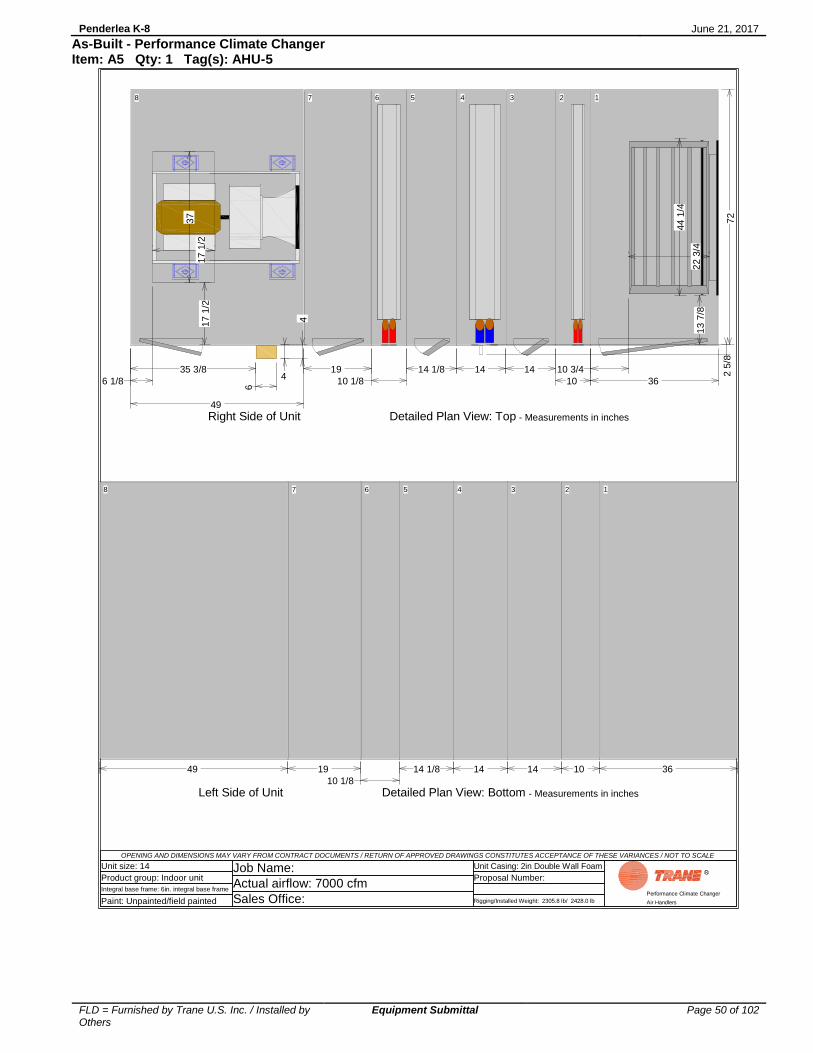
Penderlea K-8 June 21, 2017
FLD = Furnished by Trane U.S. Inc. / Installed by Others
Equipment Submittal Page 50 of 102
As-Built - Performance Climate Changer Item: A5 Qty: 1 Tag(s): AHU-5
OPENING AND DIMENSIONS MAY VARY FROM CONTRACT DOCUMENTS / RETURN OF APPROVED DRAWINGS CONSTITUTES ACCEPTANCE OF THESE VARIANCES / NOT TO SCALE
Unit size: 14
Product group: Indoor unit
Integral base frame: 6in. integral base frame
Paint: Unpainted/field painted
Job Name:
Actual airflow: 7000 cfm
Sales Office:
Unit Casing: 2in Double Wall Foam
Proposal Number:
Rigging/Installed Weight: 2305.8 lb/ 2428.0 lb
Performance Climate Changer
Air Handlers
8 357 246 1
35 3/8
6 1/8
10 3/4
6
17
1/2
22 3
/4
49
14 14 1/819
10
14
10 1/8 36
2 5
/8
4
13 7
/8
17 1
/2
4
37
44 1
/4
72
Right Side of Unit Detailed Plan View: Top - Measurements in inches
8 357 246 1
49 14 14 1/819 10 14
10 1/8
36
Left Side of Unit Detailed Plan View: Bottom - Measurements in inches

Penderlea K-8 June 21, 2017
FLD = Furnished by Trane U.S. Inc. / Installed by Others
Equipment Submittal Page 51 of 102
As-Built - Performance Climate Changer Item: A5 Qty: 1 Tag(s): AHU-5
OPENING AND DIMENSIONS MAY VARY FROM CONTRACT DOCUMENTS / RETURN OF APPROVED DRAWINGS CONSTITUTES ACCEPTANCE OF THESE VARIANCES / NOT TO SCALE
Unit size: 14
Product group: Indoor unit
Integral base frame: 6in. integral base frame
Paint: Unpainted/field painted
Job Name:
Actual airflow: 7000 cfm
Sales Office:
Unit Casing: 2in Double Wall Foam
Proposal Number:
Rigging/Installed Weight: 2305.8 lb/ 2428.0 lb
Performance Climate Changer
Air Handlers
83 5 72 4 61
49 14 14 1/8 19 10 14
10 1/8
36
6
45
Detailed Elevation View: Left - Measurements in inches
6 6 7
/8
7 3/4
11 3/4 14 1/48
34 3
/4
22 3
/4
8 357 246 1
35 3/8
6 1/8
2 5/8
2 1/82 1/82 1/8 7 2 1/8
10 3/4
6
17
1/2
18" 10"10"15" 31"
22 3
/4
1" N.P.T.E
166 1/8
45
Detailed Elevation View: Right - Measurements in inches

Penderlea K-8 June 21, 2017
FLD = Furnished by Trane U.S. Inc. / Installed by Others
Equipment Submittal Page 52 of 102
As-Built - Performance Climate Changer Item: A5 Qty: 1 Tag(s): AHU-5
OPENING AND DIMENSIONS MAY VARY FROM CONTRACT DOCUMENTS / RETURN OF APPROVED DRAWINGS CONSTITUTES ACCEPTANCE OF THESE VARIANCES / NOT TO SCALE
Unit size: 14
Product group: Indoor unit
Integral base frame: 6in. integral base frame
Paint: Unpainted/field painted
Job Name:
Actual airflow: 7000 cfm
Sales Office:
Unit Casing: 2in Double Wall Foam
Proposal Number:
Rigging/Installed Weight: 2305.8 lb/ 2428.0 lb
Performance Climate Changer
Air Handlers
1
44 1
/4
22 3
/4
13 7/8
72
6
14 1
/4
45
Detailed Elevation View: Back - Measurements in inches
8
8
11 3/4
Detailed Elevation View: Front - Measurements in inches

Penderlea K-8 June 21, 2017
FLD = Furnished by Trane U.S. Inc. / Installed by Others
Equipment Submittal Page 53 of 102
As-Built - Performance Climate Changer Item: A5 Qty: 1 Tag(s): AHU-5
OP
EN
ING
AN
D D
IME
NS
ION
S M
AY
VA
RY
FR
OM
CO
NT
RA
CT
DO
CU
ME
NT
S / R
ET
UR
N O
F A
PP
RO
VE
D D
RA
WIN
GS
CO
NS
TIT
UT
ES
AC
CE
PT
AN
CE
OF
TH
ES
E V
AR
IAN
CE
S / N
OT
TO
SC
AL
E
Unit s
ize
: 1
4
Pro
du
ct g
rou
p: In
do
or
unit
Inte
gra
l b
ase
fra
me
: 6
in. in
teg
ral b
ase
fra
me
Pa
int: U
np
ain
ted
/fie
ld p
ain
ted
Jo
b N
am
e:
Actu
al a
irflo
w: 7
00
0 c
fm
Sa
les O
ffic
e:
Un
it C
asin
g: 2in
Do
ub
le W
all
Fo
am
Pro
po
sa
l N
um
be
r:
Rig
gin
g/In
sta
lled
We
igh
t: 2
30
5.8
lb
/ 2
42
8.0
lb
Perform
ance C
limate
Changer
Air H
andle
rs
20 1
/42
3 1
/826 1
/427 3
/4
45
83
57
24
61
7 1
/4
5 1
/2
10 5
/8
5 1
/4
6 1
/8
3 7
/8
49
14
14
1/8
19
10
14
10 1
/836
1.5
" (N
PT
E)
Retu
rn
1.5
" (N
PT
E)
Supp
ly
3/8
" (N
PT
I) V
ent
3/8
" dra
in (
NP
TI)
2"
(NP
TE
) R
etu
rn
2"
(NP
TE
) S
upply
3/8
" (N
PT
I) V
ent
3/8
" d
rain
(N
PT
I)
2"
(NP
TE
) R
etu
rn
2"
(NP
TE
) S
upply
3/8
" (N
PT
I) V
ent
3/8
" dra
in (
NP
TI)
166 1
/8
Coil
co
nnection v
iew
: R
ight
- M
easu
rem
ents
in inch
es
NP
TI
: N
ati
on
al
Pip
e T
hre
ad
In
tern
al
Co
nn
ecti
on
NP
TE
: N
ati
on
al
Pip
e T
hre
ad
Exte
rna
l C
on
ne
cti
on

Penderlea K-8 June 21, 2017
FLD = Furnished by Trane U.S. Inc. / Installed by Others
Equipment Submittal Page 54 of 102
As-Built - Performance Climate Changer Item: A5 Qty: 1 Tag(s): AHU-5
OP
EN
ING
AN
D D
IME
NS
ION
S M
AY
VA
RY
FR
OM
CO
NT
RA
CT
DO
CU
ME
NT
S / R
ET
UR
N O
F A
PP
RO
VE
D D
RA
WIN
GS
CO
NS
TIT
UT
ES
AC
CE
PT
AN
CE
OF
TH
ES
E V
AR
IAN
CE
S / N
OT
TO
SC
AL
E
Unit s
ize
: 1
4
Pro
du
ct g
rou
p: In
do
or
unit
Inte
gra
l b
ase
fra
me
: 6
in. in
teg
ral b
ase
fra
me
Pa
int: U
np
ain
ted
/fie
ld p
ain
ted
Jo
b N
am
e:
Actu
al a
irflo
w: 7
00
0 c
fm
Sa
les O
ffic
e:
Un
it C
asin
g: 2in
Do
ub
le W
all
Fo
am
Pro
po
sa
l N
um
be
r:
Rig
gin
g/In
sta
lled
We
igh
t: 2
30
5.8
lb
/ 2
42
8.0
lb
Perform
ance C
limate
Changer
Air H
andle
rs
83
57
24
61
49
14
14 1
/819
10
14
10 1
/836
45
16
6 1
/8
Coil
co
nnection v
iew
: Left
- M
easu
rem
ents
in inch
es
NP
TI
: N
ati
on
al
Pip
e T
hre
ad
In
tern
al
Co
nn
ecti
on
NP
TE
: N
ati
on
al
Pip
e T
hre
ad
Exte
rna
l C
on
ne
cti
on
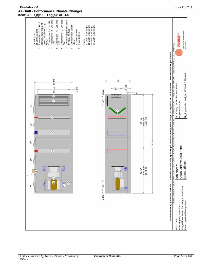
Penderlea K-8 June 21, 2017
FLD = Furnished by Trane U.S. Inc. / Installed by Others
Equipment Submittal Page 55 of 102
As-Built - Performance Climate Changer Item: A6 Qty: 1 Tag(s): AHU-6
OP
EN
ING
AN
D D
IME
NS
ION
S M
AY
VA
RY
FR
OM
CO
NT
RA
CT
DO
CU
ME
NT
S / R
ET
UR
N O
F A
PP
RO
VE
D D
RA
WIN
GS
CO
NS
TIT
UT
ES
AC
CE
PT
AN
CE
OF
TH
ES
E V
AR
IAN
CE
S / N
OT
TO
SC
AL
E
Unit s
ize
: 1
2
Pro
du
ct g
rou
p: In
do
or
unit
Inte
gra
l b
ase
fra
me
: 6
in. in
teg
ral b
ase
fra
me
Pa
int: U
np
ain
ted
/fie
ld p
ain
ted
Jo
b N
am
e:
Actu
al a
irflo
w: 5
60
0 c
fm
Sa
les O
ffic
e:
Un
it C
asin
g: 2in
Do
ub
le W
all
Fo
am
Pro
po
sa
l N
um
be
r:
Rig
gin
g/In
sta
lled
We
igh
t: 2
17
0.8
lb
/ 2
28
3.6
lb
Perform
ance C
limate
Changer
Air H
andle
rs
17
"10"
15
"15"
31"
5 1
/2
55
1/2
17 1
/4
32
4
66 1
/2
1
2
3
45
67
8
6 1
7 1
/8
17
6 1
/816
2 1
/217
9
78 1
/8S
hip
Sp
lit1074
lb
s
93 1
/8S
hip
Split
1157 lbs
171
1/8
45
1 2 3 4 5 6 7 8 9
Openin
g t
op
16
.000
x 3
2.0
00
Ple
num
fan
- 2
2.2
5in
. dd
ple
num
, 80%
wid
th,
Mpre
ss S
up
ply
fan 5
hp
46
0/3
Exte
rnal ju
nction b
ox L
HH
eating c
oil
- 2
Coil
type
UW
Co
olin
g c
oil
- 6
C
oil
type
UW
He
ating c
oil
- 1
Coil
type
5W
Da
mper
top-p
ara
llel bla
de
17
.000
x 5
5.5
00
Da
mper
back-p
ara
llel
bla
de
17
.000
x 5
5.5
00
Angle
d f
ilters
-
Do
ors
17
wid
th x
35 h
eig
ht
15
wid
th x
35 h
eig
ht
10
wid
th x
35 h
eig
ht
31
wid
th x
35 h
eig
ht
Fo
r m
an
eu
veri
ng
pu
rpo
ses,
inclu
de 1
.125 i
nch
es t
o e
ach
sh
ip s
pli
t le
ng
th f
or
overl
ap
pin
g p
an
el
flan
ge.
Fla
ng
e w
ill
no
t ad
d t
o o
vera
ll i
nsta
lled
un
it l
en
gth
sh
ow
n.

Penderlea K-8 June 21, 2017
FLD = Furnished by Trane U.S. Inc. / Installed by Others
Equipment Submittal Page 56 of 102
As-Built - Performance Climate Changer Item: A6 Qty: 1 Tag(s): AHU-6
OPENING AND DIMENSIONS MAY VARY FROM CONTRACT DOCUMENTS / RETURN OF APPROVED DRAWINGS CONSTITUTES ACCEPTANCE OF THESE VARIANCES / NOT TO SCALE
Unit size: 12
Product group: Indoor unit
Integral base frame: 6in. integral base frame
Paint: Unpainted/field painted
Job Name:
Actual airflow: 5600 cfm
Sales Office:
Unit Casing: 2in Double Wall Foam
Proposal Number:
Rigging/Installed Weight: 2170.8 lb/ 2283.6 lb
Performance Climate Changer
Air Handlers
Pos #83572461
ModuleFan sectionAccess sectionAccess sectionAccess sectionCoil sectionCoil sectionCoil sectionAir mixing section
Length49 14 19 1/819 10 14 10 1/836
Weight740.99104.42139.51129.00182.56389.92230.07367.08
Installed Unit Weight 2283.56 lbs
8 357 246 1
66 1
/2
Basic Overall Plan View: Top - Measurements in inches
S2 S1
6
8 357 246 1
171 1/8
45
Overall Elevation View: Right - Shipping splits indicated by bold outline. - Measurements in inches
For maneuvering purposes, include 1.125 inches to each ship split length for overlapping panel flange. Flange will not add to overall installed unit length shown.

Penderlea K-8 June 21, 2017
FLD = Furnished by Trane U.S. Inc. / Installed by Others
Equipment Submittal Page 57 of 102
As-Built - Performance Climate Changer Item: A6 Qty: 1 Tag(s): AHU-6
OPENING AND DIMENSIONS MAY VARY FROM CONTRACT DOCUMENTS / RETURN OF APPROVED DRAWINGS CONSTITUTES ACCEPTANCE OF THESE VARIANCES / NOT TO SCALE
Unit size: 12
Product group: Indoor unit
Integral base frame: 6in. integral base frame
Paint: Unpainted/field painted
Job Name:
Actual airflow: 5600 cfm
Sales Office:
Unit Casing: 2in Double Wall Foam
Proposal Number:
Rigging/Installed Weight: 2170.8 lb/ 2283.6 lb
Performance Climate Changer
Air Handlers
8 357 246 1
6 1/8 16 1/2
16
17
49
14 19 1/819 10 14
10 1/8 36 5 1
/2
17 1
/4
32
55
1/2
66 1
/2
Right Side of Unit Detailed Plan View: Top - Measurements in inches
8 357 246 1
49 14 19 1/819 10 14
10 1/8
36
Left Side of Unit Detailed Plan View: Bottom - Measurements in inches
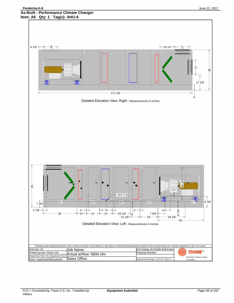
Penderlea K-8 June 21, 2017
FLD = Furnished by Trane U.S. Inc. / Installed by Others
Equipment Submittal Page 58 of 102
As-Built - Performance Climate Changer Item: A6 Qty: 1 Tag(s): AHU-6
OPENING AND DIMENSIONS MAY VARY FROM CONTRACT DOCUMENTS / RETURN OF APPROVED DRAWINGS CONSTITUTES ACCEPTANCE OF THESE VARIANCES / NOT TO SCALE
Unit size: 12
Product group: Indoor unit
Integral base frame: 6in. integral base frame
Paint: Unpainted/field painted
Job Name:
Actual airflow: 5600 cfm
Sales Office:
Unit Casing: 2in Double Wall Foam
Proposal Number:
Rigging/Installed Weight: 2170.8 lb/ 2283.6 lb
Performance Climate Changer
Air Handlers
83 5 72 4 61
6
17"10" 15" 15"31"
8
34 3
/4
7 5/8
29 1/8
2 2 2 7 2 7/8
49
14 19 1/8
19
10 14
10 1/8
36
1" N.P.T.E
6 6 7
/8
7 3/411 3/4
45
Detailed Elevation View: Left - Measurements in inches
6
17 1/8
17
8 357 246 1
6 1/8 16 1/216
17
171 1/8
45
Detailed Elevation View: Right - Measurements in inches

Penderlea K-8 June 21, 2017
FLD = Furnished by Trane U.S. Inc. / Installed by Others
Equipment Submittal Page 59 of 102
As-Built - Performance Climate Changer Item: A6 Qty: 1 Tag(s): AHU-6
OPENING AND DIMENSIONS MAY VARY FROM CONTRACT DOCUMENTS / RETURN OF APPROVED DRAWINGS CONSTITUTES ACCEPTANCE OF THESE VARIANCES / NOT TO SCALE
Unit size: 12
Product group: Indoor unit
Integral base frame: 6in. integral base frame
Paint: Unpainted/field painted
Job Name:
Actual airflow: 5600 cfm
Sales Office:
Unit Casing: 2in Double Wall Foam
Proposal Number:
Rigging/Installed Weight: 2170.8 lb/ 2283.6 lb
Performance Climate Changer
Air Handlers
1
55 1
/2
8
17
5 1/2
66 1/2
6
11 3/4
17 1
/8
45
Detailed Elevation View: Back - Measurements in inches
8
Detailed Elevation View: Front - Measurements in inches

Penderlea K-8 June 21, 2017
FLD = Furnished by Trane U.S. Inc. / Installed by Others
Equipment Submittal Page 60 of 102
As-Built - Performance Climate Changer Item: A6 Qty: 1 Tag(s): AHU-6
OP
EN
ING
AN
D D
IME
NS
ION
S M
AY
VA
RY
FR
OM
CO
NT
RA
CT
DO
CU
ME
NT
S / R
ET
UR
N O
F A
PP
RO
VE
D D
RA
WIN
GS
CO
NS
TIT
UT
ES
AC
CE
PT
AN
CE
OF
TH
ES
E V
AR
IAN
CE
S / N
OT
TO
SC
AL
E
Unit s
ize
: 1
2
Pro
du
ct g
rou
p: In
do
or
unit
Inte
gra
l b
ase
fra
me
: 6
in. in
teg
ral b
ase
fra
me
Pa
int: U
np
ain
ted
/fie
ld p
ain
ted
Jo
b N
am
e:
Actu
al a
irflo
w: 5
60
0 c
fm
Sa
les O
ffic
e:
Un
it C
asin
g: 2in
Do
ub
le W
all
Fo
am
Pro
po
sa
l N
um
be
r:
Rig
gin
g/In
sta
lled
We
igh
t: 2
17
0.8
lb
/ 2
28
3.6
lb
Perform
ance C
limate
Changer
Air H
andle
rs
45
83
57
24
61
49
14
19 1
/819
10
14
10 1
/836
171 1
/8
Coil
co
nnection v
iew
: R
ight
- M
easu
rem
ents
in inch
es
NP
TI
: N
ati
on
al
Pip
e T
hre
ad
In
tern
al
Co
nn
ecti
on
NP
TE
: N
ati
on
al
Pip
e T
hre
ad
Exte
rna
l C
on
ne
cti
on

Penderlea K-8 June 21, 2017
FLD = Furnished by Trane U.S. Inc. / Installed by Others
Equipment Submittal Page 61 of 102
As-Built - Performance Climate Changer Item: A6 Qty: 1 Tag(s): AHU-6
OP
EN
ING
AN
D D
IME
NS
ION
S M
AY
VA
RY
FR
OM
CO
NT
RA
CT
DO
CU
ME
NT
S / R
ET
UR
N O
F A
PP
RO
VE
D D
RA
WIN
GS
CO
NS
TIT
UT
ES
AC
CE
PT
AN
CE
OF
TH
ES
E V
AR
IAN
CE
S / N
OT
TO
SC
AL
E
Unit s
ize
: 1
2
Pro
du
ct g
rou
p: In
do
or
unit
Inte
gra
l b
ase
fra
me
: 6
in. in
teg
ral b
ase
fra
me
Pa
int: U
np
ain
ted
/fie
ld p
ain
ted
Jo
b N
am
e:
Actu
al a
irflo
w: 5
60
0 c
fm
Sa
les O
ffic
e:
Un
it C
asin
g: 2in
Do
ub
le W
all
Fo
am
Pro
po
sa
l N
um
be
r:
Rig
gin
g/In
sta
lled
We
igh
t: 2
17
0.8
lb
/ 2
28
3.6
lb
Perform
ance C
limate
Changer
Air H
andle
rs
83
57
24
61
2 3
/4
4 1
/2
3 3
/8
8 3
/4
3 7
/8
6 1
/8
49
14
19 1
/819
10
14
10 1
/836
1.5
" (N
PT
E)
Retu
rn
1.5
" (N
PT
E)
Supply
3/8
" (N
PT
I) V
en
t
3/8
" dra
in (
NP
TI)
2"
(NP
TE
) R
etu
rn
2"
(NP
TE
) S
upply
3/8
" (N
PT
I) V
en
t
3/8
" dra
in (
NP
TI)
2"
(NP
TE
) R
etu
rn
2"
(NP
TE
) S
upply
3/8
" (N
PT
I) V
ent
3/8
" dra
in (
NP
TI)
20 1
/423 1
/82
6 1
/427 3
/4
45
171 1
/8
Coil
co
nnection v
iew
: Left
- M
easu
rem
ents
in inch
es
NP
TI
: N
ati
on
al
Pip
e T
hre
ad
In
tern
al
Co
nn
ecti
on
NP
TE
: N
ati
on
al
Pip
e T
hre
ad
Exte
rna
l C
on
ne
cti
on

Penderlea K-8 June 21, 2017
FLD = Furnished by Trane U.S. Inc. / Installed by Others
Equipment Submittal Page 62 of 102
As-Built - Performance Climate Changer Item: A7 Qty: 1 Tag(s): AHU-7
OP
EN
ING
AN
D D
IME
NS
ION
S M
AY
VA
RY
FR
OM
CO
NT
RA
CT
DO
CU
ME
NT
S / R
ET
UR
N O
F A
PP
RO
VE
D D
RA
WIN
GS
CO
NS
TIT
UT
ES
AC
CE
PT
AN
CE
OF
TH
ES
E V
AR
IAN
CE
S / N
OT
TO
SC
AL
E
Unit s
ize
: 3
5
Pro
du
ct g
rou
p: In
do
or
unit
Inte
gra
l b
ase
fra
me
: 6
in. in
teg
ral b
ase
fra
me
Pa
int: U
np
ain
ted
/fie
ld p
ain
ted
Jo
b N
am
e:
Actu
al a
irflo
w: 1
58
00
cfm
Sa
les O
ffic
e:
Un
it C
asin
g: 2in
Do
ub
le W
all
Fo
am
Pro
po
sa
l N
um
be
r:
Rig
gin
g/In
sta
lled
We
igh
t: 4
94
4.5
lb
/ 5
30
6.4
lb
Perform
ance C
limate
Changer
Air H
andle
rs
22"
10"
15
"15"
20"
15 1
/2
69
17
1/2
65
7 7
/8
100
1
2
3
45
67
8
6 2
1 1
/8
34 1
/4
14
1/4
29
6 1
/234 1
/4
9
56 5
/8S
hip
Sp
lit1573
lbs
72 1
/8S
hip
Split
1519 lbs
62 1
/8S
hip
Split
2114 lbs
190 3
/4
70 3
/4
1 2 3 4 5 6 7 8 9
Openin
g t
op
29.0
00 x
65.0
00
Ple
num
fa
n -
22.2
5in
. d
dp
lenum
, fu
ll w
idth
, M
pre
ss
Sup
ply
fan 1
0 h
p 4
60/3
Overloa
d b
ox L
HH
eating c
oil
- 2
Coil
typ
eU
WC
oolin
g c
oil
- 8
Coil
type
UW
Heating c
oil
- 1
Coil
typ
e5
WD
am
pe
r to
p-p
ara
llel bla
de
34.2
50 x
69.0
00
Dam
pe
r ba
ck-p
ara
llel
bla
de
34.2
50 x
69.0
00
Ang
led f
ilters
-
Doors
22 w
idth
x 6
1 h
eig
ht
15 w
idth
x 6
1 h
eig
ht
10 w
idth
x 6
1 h
eig
ht
20 w
idth
x 6
1 h
eig
ht
Fo
r m
an
eu
veri
ng
pu
rpo
ses,
inclu
de 1
.125 i
nch
es t
o e
ach
sh
ip s
pli
t le
ng
th f
or
overl
ap
pin
g p
an
el
flan
ge.
Fla
ng
e w
ill
no
t ad
d t
o o
vera
ll i
nsta
lled
un
it l
en
gth
sh
ow
n.

Penderlea K-8 June 21, 2017
FLD = Furnished by Trane U.S. Inc. / Installed by Others
Equipment Submittal Page 63 of 102
As-Built - Performance Climate Changer Item: A7 Qty: 1 Tag(s): AHU-7
OPENING AND DIMENSIONS MAY VARY FROM CONTRACT DOCUMENTS / RETURN OF APPROVED DRAWINGS CONSTITUTES ACCEPTANCE OF THESE VARIANCES / NOT TO SCALE
Unit size: 35
Product group: Indoor unit
Integral base frame: 6in. integral base frame
Paint: Unpainted/field painted
Job Name:
Actual airflow: 15800 cfm
Sales Office:
Unit Casing: 2in Double Wall Foam
Proposal Number:
Rigging/Installed Weight: 4944.5 lb/ 5306.4 lb
Performance Climate Changer
Air Handlers
Pos #83572461
ModuleFan sectionAccess sectionAccess sectionAccess sectionCoil sectionCoil sectionCoil sectionAir mixing section
Length56 5/814 1/819 19 1/810 14 1/810 48
Weight1622.45262.22286.00301.80399.861047.62498.46887.97
Installed Unit Weight 5306.40 lbs
8 357 246 1
100
Basic Overall Plan View: Top - Measurements in inches
S3 S1S2
6
8 357 246 1
190 3/4
70 3
/4
Overall Elevation View: Right - Shipping splits indicated by bold outline. - Measurements in inches
For maneuvering purposes, include 1.125 inches to each ship split length for overlapping panel flange. Flange will not add to overall installed unit length shown.

Penderlea K-8 June 21, 2017
FLD = Furnished by Trane U.S. Inc. / Installed by Others
Equipment Submittal Page 64 of 102
As-Built - Performance Climate Changer Item: A7 Qty: 1 Tag(s): AHU-7
OPENING AND DIMENSIONS MAY VARY FROM CONTRACT DOCUMENTS / RETURN OF APPROVED DRAWINGS CONSTITUTES ACCEPTANCE OF THESE VARIANCES / NOT TO SCALE
Unit size: 35
Product group: Indoor unit
Integral base frame: 6in. integral base frame
Paint: Unpainted/field painted
Job Name:
Actual airflow: 15800 cfm
Sales Office:
Unit Casing: 2in Double Wall Foam
Proposal Number:
Rigging/Installed Weight: 4944.5 lb/ 5306.4 lb
Performance Climate Changer
Air Handlers
8 357 246 1
14 1/4
43
7 1/4
29
34 1
/4
56 5/8
14 1/819 19 1/8
10
14 1/810
48
1.378 dia elec con(NEMA)
15 1
/2
17 1
/295 6
5
69
100
Right Side of Unit Detailed Plan View: Top - Measurements in inches
8 357 246 1
56 5/8 14 1/819 19 1/8 10 14 1/810 48
Left Side of Unit Detailed Plan View: Bottom - Measurements in inches

Penderlea K-8 June 21, 2017
FLD = Furnished by Trane U.S. Inc. / Installed by Others
Equipment Submittal Page 65 of 102
As-Built - Performance Climate Changer Item: A7 Qty: 1 Tag(s): AHU-7
OPENING AND DIMENSIONS MAY VARY FROM CONTRACT DOCUMENTS / RETURN OF APPROVED DRAWINGS CONSTITUTES ACCEPTANCE OF THESE VARIANCES / NOT TO SCALE
Unit size: 35
Product group: Indoor unit
Integral base frame: 6in. integral base frame
Paint: Unpainted/field painted
Job Name:
Actual airflow: 15800 cfm
Sales Office:
Unit Casing: 2in Double Wall Foam
Proposal Number:
Rigging/Installed Weight: 4944.5 lb/ 5306.4 lb
Performance Climate Changer
Air Handlers
83 5 72 4 61
20 1
/8
22"10" 15" 15"20"
20
60 1
/2
1 7/8
32
2 2 2
7 1/8
25 1/2
56 5/8
14 1/8
19
19 1/8
10
14 1/8
10 48
1.25" N.P.T.E
6 6 7
/8
7 3/4
26 1/4
70 3
/4
Detailed Elevation View: Left - Measurements in inches
6
21 1/8
34 1
/4
8 357 246 1
14 1/4 7 1/429
34
1/4
190 3/4
70 3
/4
Detailed Elevation View: Right - Measurements in inches

Penderlea K-8 June 21, 2017
FLD = Furnished by Trane U.S. Inc. / Installed by Others
Equipment Submittal Page 66 of 102
As-Built - Performance Climate Changer Item: A7 Qty: 1 Tag(s): AHU-7
OPENING AND DIMENSIONS MAY VARY FROM CONTRACT DOCUMENTS / RETURN OF APPROVED DRAWINGS CONSTITUTES ACCEPTANCE OF THESE VARIANCES / NOT TO SCALE
Unit size: 35
Product group: Indoor unit
Integral base frame: 6in. integral base frame
Paint: Unpainted/field painted
Job Name:
Actual airflow: 15800 cfm
Sales Office:
Unit Casing: 2in Double Wall Foam
Proposal Number:
Rigging/Installed Weight: 4944.5 lb/ 5306.4 lb
Performance Climate Changer
Air Handlers
1
69
20
34
1/4
15 1/2
100 6
21 1
/8 26 1/4
70 3
/4
Detailed Elevation View: Back - Measurements in inches
8
6
Detailed Elevation View: Front - Measurements in inches
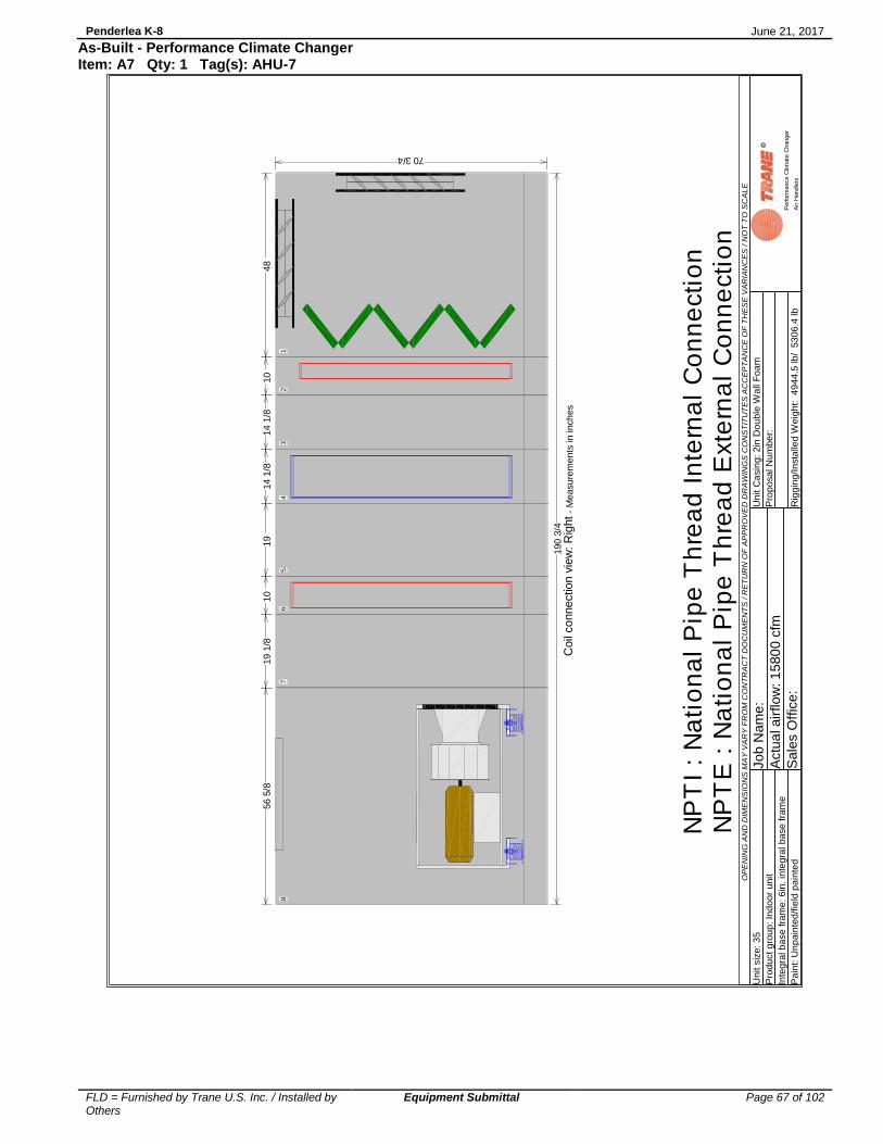
Penderlea K-8 June 21, 2017
FLD = Furnished by Trane U.S. Inc. / Installed by Others
Equipment Submittal Page 67 of 102
As-Built - Performance Climate Changer Item: A7 Qty: 1 Tag(s): AHU-7
OP
EN
ING
AN
D D
IME
NS
ION
S M
AY
VA
RY
FR
OM
CO
NT
RA
CT
DO
CU
ME
NT
S / R
ET
UR
N O
F A
PP
RO
VE
D D
RA
WIN
GS
CO
NS
TIT
UT
ES
AC
CE
PT
AN
CE
OF
TH
ES
E V
AR
IAN
CE
S / N
OT
TO
SC
AL
E
Unit s
ize
: 3
5
Pro
du
ct g
rou
p: In
do
or
unit
Inte
gra
l b
ase
fra
me
: 6
in. in
teg
ral b
ase
fra
me
Pa
int: U
np
ain
ted
/fie
ld p
ain
ted
Jo
b N
am
e:
Actu
al a
irflo
w: 1
58
00
cfm
Sa
les O
ffic
e:
Un
it C
asin
g: 2in
Do
ub
le W
all
Fo
am
Pro
po
sa
l N
um
be
r:
Rig
gin
g/In
sta
lled
We
igh
t: 4
94
4.5
lb
/ 5
30
6.4
lb
Perform
ance C
limate
Changer
Air H
andle
rs
70 3/4
83
57
24
61
56 5
/814 1
/819
19 1
/810
14 1
/810
48
190 3
/4
Coil
co
nnection v
iew
: R
ight
- M
easu
rem
ents
in inch
es
NP
TI
: N
ati
on
al
Pip
e T
hre
ad
In
tern
al
Co
nn
ecti
on
NP
TE
: N
ati
on
al
Pip
e T
hre
ad
Exte
rna
l C
on
ne
cti
on

Penderlea K-8 June 21, 2017
FLD = Furnished by Trane U.S. Inc. / Installed by Others
Equipment Submittal Page 68 of 102
As-Built - Performance Climate Changer Item: A7 Qty: 1 Tag(s): AHU-7
OP
EN
ING
AN
D D
IME
NS
ION
S M
AY
VA
RY
FR
OM
CO
NT
RA
CT
DO
CU
ME
NT
S / R
ET
UR
N O
F A
PP
RO
VE
D D
RA
WIN
GS
CO
NS
TIT
UT
ES
AC
CE
PT
AN
CE
OF
TH
ES
E V
AR
IAN
CE
S / N
OT
TO
SC
AL
E
Unit s
ize
: 3
5
Pro
du
ct g
rou
p: In
do
or
unit
Inte
gra
l b
ase
fra
me
: 6
in. in
teg
ral b
ase
fra
me
Pa
int: U
np
ain
ted
/fie
ld p
ain
ted
Jo
b N
am
e:
Actu
al a
irflo
w: 1
58
00
cfm
Sa
les O
ffic
e:
Un
it C
asin
g: 2in
Do
ub
le W
all
Fo
am
Pro
po
sa
l N
um
be
r:
Rig
gin
g/In
sta
lled
We
igh
t: 4
94
4.5
lb
/ 5
30
6.4
lb
Perform
ance C
limate
Changer
Air H
andle
rs
83
57
24
61
2 3
/4
4 1
/2
3 3
/8
10 7
/8
3 5
/8
6 3
/8
56
5/8
14 1
/819
19 1
/810
14 1
/81
0
48
1.5
" (N
PT
E)
Retu
rn
1.5
" (N
PT
E)
Supply
3/8
" (N
PT
I) V
en
t
3/8
" dra
in (
NP
TI)
2.5
" (N
PT
E)
Retu
rn
2.5
" (N
PT
E)
Supply
3/8
" (N
PT
I) V
en
t
3/8
" dra
in (
NP
TI)
2.5
" (N
PT
E)
Retu
rn
2.5
" (N
PT
E)
Supply
3/8
" (N
PT
I) V
ent
3/8
" dra
in (
NP
TI)
33 1
/836 1
/239 5
/840 5
/8
70 3/4
190 3
/4
Coil
co
nnection v
iew
: Left
- M
easu
rem
ents
in inch
es
NP
TI
: N
ati
on
al
Pip
e T
hre
ad
In
tern
al
Co
nn
ecti
on
NP
TE
: N
ati
on
al
Pip
e T
hre
ad
Exte
rna
l C
on
ne
cti
on

Penderlea K-8 June 21, 2017
FLD = Furnished by Trane U.S. Inc. / Installed by Others
Equipment Submittal Page 69 of 102
As-Built - Performance Climate Changer Item: A8 Qty: 1 Tag(s): AHU-8
OP
EN
ING
AN
D D
IME
NS
ION
S M
AY
VA
RY
FR
OM
CO
NT
RA
CT
DO
CU
ME
NT
S / R
ET
UR
N O
F A
PP
RO
VE
D D
RA
WIN
GS
CO
NS
TIT
UT
ES
AC
CE
PT
AN
CE
OF
TH
ES
E V
AR
IAN
CE
S / N
OT
TO
SC
AL
E
Unit s
ize
: 6
Pro
du
ct g
rou
p: In
do
or
unit
Inte
gra
l b
ase
fra
me
: 6
in. in
teg
ral b
ase
fra
me
Pa
int: U
np
ain
ted
/fie
ld p
ain
ted
Jo
b N
am
e:
Actu
al a
irflo
w: 3
10
0 c
fm
Sa
les O
ffic
e:
Un
it C
asin
g: 2in
Do
ub
le W
all
Fo
am
Pro
po
sa
l N
um
be
r:
Rig
gin
g/In
sta
lled
We
igh
t: 1
33
0.3
lb
/ 1
37
8.6
lb
Perform
ance C
limate
Changer
Air H
andle
rs
17
"15"
15"
29"
7 7
/8
28 1
/4
11 1
/2
21
4
44
12
3
45
67
6 1
1 3
/4
17
6 7
/815
2 1
/21
7
1"
N.P
.T.E9
62
7/8
Ship
Split
62
4 lbs
77 1
/8S
hip
Sp
lit710
lbs
13
9 7
/8
38
3/4
1 2 3 4 5 6 7 8 9
Openin
g t
op
15
.000
x 2
1.0
00
Ple
num
fan
- 1
6.5
in.
dd
ple
num
, 80%
wid
th,
Mpre
ss S
up
ply
fan 5
hp
46
0/3
Exte
rnal ju
nction b
ox R
HH
eating c
oil
- 2
Coil
type
UW
Co
olin
g c
oil
- 6
C
oil
type
UW
Da
mper
top-p
ara
llel bla
de
17
.000
x 2
8.2
50
Da
mper
back-p
ara
llel
bla
de
17
.000
x 2
8.2
50
1"
N.P
.T.E
Angle
d f
ilters
-
Do
ors
17
wid
th x
29 h
eig
ht
15
wid
th x
29 h
eig
ht
29
wid
th x
29 h
eig
ht
Fo
r m
an
eu
veri
ng
pu
rpo
ses,
inclu
de 1
.125 i
nch
es t
o e
ach
sh
ip s
pli
t le
ng
th f
or
overl
ap
pin
g p
an
el
flan
ge.
Fla
ng
e w
ill
no
t ad
d t
o o
vera
ll i
nsta
lled
un
it l
en
gth
sh
ow
n.
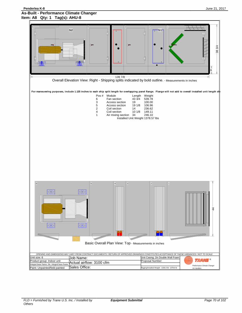
Penderlea K-8 June 21, 2017
FLD = Furnished by Trane U.S. Inc. / Installed by Others
Equipment Submittal Page 70 of 102
As-Built - Performance Climate Changer Item: A8 Qty: 1 Tag(s): AHU-8
OPENING AND DIMENSIONS MAY VARY FROM CONTRACT DOCUMENTS / RETURN OF APPROVED DRAWINGS CONSTITUTES ACCEPTANCE OF THESE VARIANCES / NOT TO SCALE
Unit size: 6
Product group: Indoor unit
Integral base frame: 6in. integral base frame
Paint: Unpainted/field painted
Job Name:
Actual airflow: 3100 cfm
Sales Office:
Unit Casing: 2in Double Wall Foam
Proposal Number:
Rigging/Installed Weight: 1330.3 lb/ 1378.6 lb
Performance Climate Changer
Air Handlers
Pos #635241
ModuleFan sectionAccess sectionAccess sectionCoil sectionCoil sectionAir mixing section
Length43 3/419 19 1/814 10 1/834
Weight539.78100.00106.96236.62149.11246.10
Installed Unit Weight 1378.57 lbs
6 35 24 1
44
Basic Overall Plan View: Top - Measurements in inches
S2 S1
6
6 35 24 1
139 7/8
38 3
/4
Overall Elevation View: Right - Shipping splits indicated by bold outline. - Measurements in inches
For maneuvering purposes, include 1.125 inches to each ship split length for overlapping panel flange. Flange will not add to overall installed unit length shown.

Penderlea K-8 June 21, 2017
FLD = Furnished by Trane U.S. Inc. / Installed by Others
Equipment Submittal Page 71 of 102
As-Built - Performance Climate Changer Item: A8 Qty: 1 Tag(s): AHU-8
OPENING AND DIMENSIONS MAY VARY FROM CONTRACT DOCUMENTS / RETURN OF APPROVED DRAWINGS CONSTITUTES ACCEPTANCE OF THESE VARIANCES / NOT TO SCALE
Unit size: 6
Product group: Indoor unit
Integral base frame: 6in. integral base frame
Paint: Unpainted/field painted
Job Name:
Actual airflow: 3100 cfm
Sales Office:
Unit Casing: 2in Double Wall Foam
Proposal Number:
Rigging/Installed Weight: 1330.3 lb/ 1378.6 lb
Performance Climate Changer
Air Handlers
6 35 24 1
30 1/8
6 7/8
14 1/2
6
15
17
43 3/4
19 19 1/8 14 10 1/8
34
2 5
/8
4
7 7
/8
11 1
/2
4
21
28 1
/4
44
Right Side of Unit Detailed Plan View: Top - Measurements in inches
6 35 24 1
43 3/4 19 19 1/8 14 10 1/8 34
Left Side of Unit Detailed Plan View: Bottom - Measurements in inches

Penderlea K-8 June 21, 2017
FLD = Furnished by Trane U.S. Inc. / Installed by Others
Equipment Submittal Page 72 of 102
As-Built - Performance Climate Changer Item: A8 Qty: 1 Tag(s): AHU-8
OPENING AND DIMENSIONS MAY VARY FROM CONTRACT DOCUMENTS / RETURN OF APPROVED DRAWINGS CONSTITUTES ACCEPTANCE OF THESE VARIANCES / NOT TO SCALE
Unit size: 6
Product group: Indoor unit
Integral base frame: 6in. integral base frame
Paint: Unpainted/field painted
Job Name:
Actual airflow: 3100 cfm
Sales Office:
Unit Casing: 2in Double Wall Foam
Proposal Number:
Rigging/Installed Weight: 1330.3 lb/ 1378.6 lb
Performance Climate Changer
Air Handlers
63 52 41
43 3/419 19 1/814 10 1/834
6
38 3
/4
Detailed Elevation View: Left - Measurements in inches
6 6 7
/8
7 3/411 3/411 3/4
8
28 1
/2
17
6 35 24 1
30 1/8
6 7/8
2 5/8
2 1/82 1/8 7 2 1/8
14 1/2
6
15
17" 15"15" 29"
17
1" N.P.T.E
139 7/8
38 3
/4
Detailed Elevation View: Right - Measurements in inches
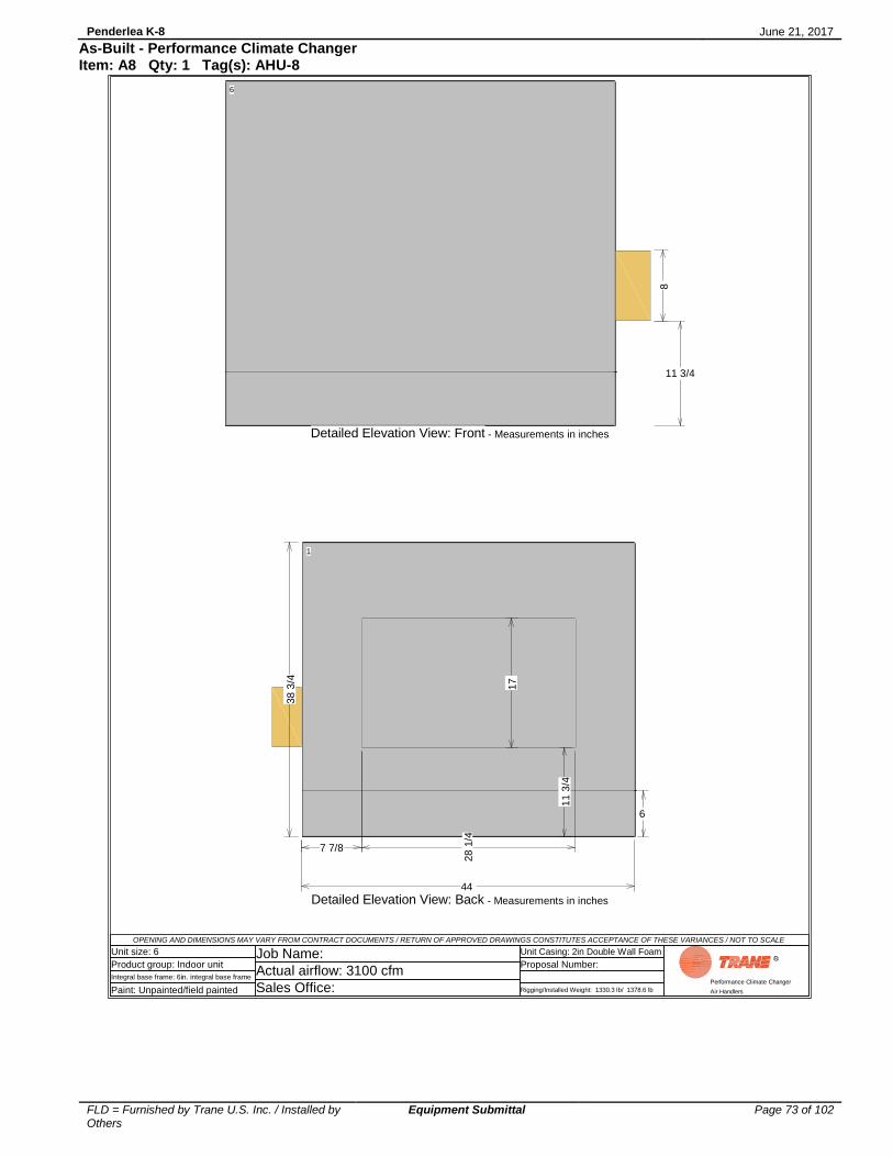
Penderlea K-8 June 21, 2017
FLD = Furnished by Trane U.S. Inc. / Installed by Others
Equipment Submittal Page 73 of 102
As-Built - Performance Climate Changer Item: A8 Qty: 1 Tag(s): AHU-8
OPENING AND DIMENSIONS MAY VARY FROM CONTRACT DOCUMENTS / RETURN OF APPROVED DRAWINGS CONSTITUTES ACCEPTANCE OF THESE VARIANCES / NOT TO SCALE
Unit size: 6
Product group: Indoor unit
Integral base frame: 6in. integral base frame
Paint: Unpainted/field painted
Job Name:
Actual airflow: 3100 cfm
Sales Office:
Unit Casing: 2in Double Wall Foam
Proposal Number:
Rigging/Installed Weight: 1330.3 lb/ 1378.6 lb
Performance Climate Changer
Air Handlers
1
28
1/4
17
7 7/8
44
6
11 3
/4
38 3
/4
Detailed Elevation View: Back - Measurements in inches
6
8
11 3/4
Detailed Elevation View: Front - Measurements in inches

Penderlea K-8 June 21, 2017
FLD = Furnished by Trane U.S. Inc. / Installed by Others
Equipment Submittal Page 74 of 102
As-Built - Performance Climate Changer Item: A8 Qty: 1 Tag(s): AHU-8
OP
EN
ING
AN
D D
IME
NS
ION
S M
AY
VA
RY
FR
OM
CO
NT
RA
CT
DO
CU
ME
NT
S / R
ET
UR
N O
F A
PP
RO
VE
D D
RA
WIN
GS
CO
NS
TIT
UT
ES
AC
CE
PT
AN
CE
OF
TH
ES
E V
AR
IAN
CE
S / N
OT
TO
SC
AL
E
Unit s
ize
: 6
Pro
du
ct g
rou
p: In
do
or
unit
Inte
gra
l b
ase
fra
me
: 6
in. in
teg
ral b
ase
fra
me
Pa
int: U
np
ain
ted
/fie
ld p
ain
ted
Jo
b N
am
e:
Actu
al a
irflo
w: 3
10
0 c
fm
Sa
les O
ffic
e:
Un
it C
asin
g: 2in
Do
ub
le W
all
Fo
am
Pro
po
sa
l N
um
be
r:
Rig
gin
g/In
sta
lled
We
igh
t: 1
33
0.3
lb
/ 1
37
8.6
lb
Perform
ance C
limate
Changer
Air H
andle
rs
20
23 1
/8
38 3/4
63
52
41
10 5
/8
5 1
/4
5 7
/8
4 1
/8
43 3
/419
19 1
/814
10 1
/834
1.5
" (N
PT
E)
Retu
rn
1.5
" (N
PT
E)
Supply
3/8
" (N
PT
I) V
ent
3/8
" dra
in (
NP
TI)
1.5
" (N
PT
E)
Retu
rn
1.5
" (N
PT
E)
Supply
3/8
" (N
PT
I) V
ent
3/8
" dra
in (
NP
TI)
139 7
/8
Coil
co
nnection v
iew
: R
ight
- M
easu
rem
ents
in inch
es
NP
TI
: N
ati
on
al
Pip
e T
hre
ad
In
tern
al
Co
nn
ecti
on
NP
TE
: N
ati
on
al
Pip
e T
hre
ad
Exte
rna
l C
on
ne
cti
on

Penderlea K-8 June 21, 2017
FLD = Furnished by Trane U.S. Inc. / Installed by Others
Equipment Submittal Page 75 of 102
As-Built - Performance Climate Changer Item: A8 Qty: 1 Tag(s): AHU-8
OP
EN
ING
AN
D D
IME
NS
ION
S M
AY
VA
RY
FR
OM
CO
NT
RA
CT
DO
CU
ME
NT
S / R
ET
UR
N O
F A
PP
RO
VE
D D
RA
WIN
GS
CO
NS
TIT
UT
ES
AC
CE
PT
AN
CE
OF
TH
ES
E V
AR
IAN
CE
S / N
OT
TO
SC
AL
E
Unit s
ize
: 6
Pro
du
ct g
rou
p: In
do
or
unit
Inte
gra
l b
ase
fra
me
: 6
in. in
teg
ral b
ase
fra
me
Pa
int: U
np
ain
ted
/fie
ld p
ain
ted
Jo
b N
am
e:
Actu
al a
irflo
w: 3
10
0 c
fm
Sa
les O
ffic
e:
Un
it C
asin
g: 2in
Do
ub
le W
all
Fo
am
Pro
po
sa
l N
um
be
r:
Rig
gin
g/In
sta
lled
We
igh
t: 1
33
0.3
lb
/ 1
37
8.6
lb
Perform
ance C
limate
Changer
Air H
andle
rs
63
52
41
43 3
/419
19
1/8
14
10 1
/834
38 3/4
139 7
/8
Coil
co
nnection v
iew
: Left
- M
easu
rem
ents
in inch
es
NP
TI
: N
ati
on
al
Pip
e T
hre
ad
In
tern
al
Co
nn
ecti
on
NP
TE
: N
ati
on
al
Pip
e T
hre
ad
Exte
rna
l C
on
ne
cti
on
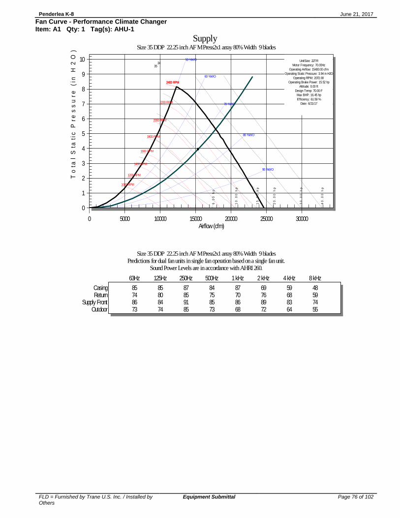
Penderlea K-8 June 21, 2017
FLD = Furnished by Trane U.S. Inc. / Installed by Others
Equipment Submittal Page 76 of 102
Fan Curve - Performance Climate Changer Item: A1 Qty: 1 Tag(s): AHU-1
6.
00
h
p
10
.0
0
hp
15
.0
0
hp
20
.0
0
hp
30
.0
0
hp
40
.0
0
hp
1000 RPM
1200 RPM
1400 RPM
1600 RPM
1800 RPM
2000 RPM
2200 RPM
2400 RPM2403 RPM
50 %WO
60 %WO
70 %WO
80 %WO
90 %WO
UnitSize: 22TR
Motor Frequency: 70.00Hz
Operating Airflow: 15400.00 cfm
Operating Static Pressure: 3.94 in H2O
Operating RPM: 2072.00
Operating Brake Power: 15.52 hp
Altitude: 0.00 ft
Design Temp: 70.00 F
Max BHP: 16.45 hp
Efficiency: 61.59 %
Date: 6/21/17
34
35
0
1
2
3
4
5
6
7
8
9
10
0 5000 10000 15000 20000 25000 30000
Supply Size 35 DDP 22.25 inch AF M Press2x1 array 80% Width 9 blades
To
tal
Sta
tic
Pr
es
su
re
(in
H2
O)
Airflow (cfm)
Size 35 DDP 22.25 inch AF M Press2x1 array 80% Width 9 bladesPredictions for dual fan units in single fan operation based on a single fan unit.
Sound Power Levels are in accordance with AHRI 260.
63Hz 125Hz 250Hz 500Hz 1 kHz 2 kHz 4 kHz 8 kHz
Casing 85 85 87 84 87 69 59 48Return 74 80 85 75 70 76 68 59
Supply Front 86 84 91 85 86 89 83 74Outdoor 73 74 85 73 68 72 64 55

Penderlea K-8 June 21, 2017
FLD = Furnished by Trane U.S. Inc. / Installed by Others
Equipment Submittal Page 77 of 102
Fan Curve - Performance Climate Changer Item: A1 Qty: 1 Tag(s): AHU-1
3.
00
h
p
5.
00
h
p
7.
50
h
p
10
.0
0
hp
15
.0
0 h
p
20
.0
0 h
p
1000 RPM
1200 RPM
1400 RPM
1600 RPM
1800 RPM
2000 RPM
2200 RPM
2400 RPM2403 RPM
50 %WO
60 %WO
70 %WO
80 %WO
90 %WO
UnitSize: 22TR
Motor Frequency: 70.00Hz
Operating Airflow: 7700.00 cfm
Operating Static Pressure: 3.94 in H2O
Operating RPM: 2072.00
Operating Brake Power: 7.76 hp
Altitude: 0.00 ft
Design Temp: 70.00 F
Max BHP: 8.23 hp
Efficiency: 61.59 %
Date: 6/21/17
34
35
0
1
2
3
4
5
6
7
8
9
10
0 2500 5000 7500 10000 12500 15000
Supply Size 35 DDP 22.25 inch AF M Press2x1 array 80% Width 9 blades - Single Fan
To
tal
Sta
tic
Pre
ss
ure
(in
H2
O)
Airflow (cfm)

Penderlea K-8 June 21, 2017
FLD = Furnished by Trane U.S. Inc. / Installed by Others
Equipment Submittal Page 78 of 102
Fan Curve - Performance Climate Changer Item: A2 Qty: 1 Tag(s): AHU-2
6.
00
h
p
10
.0
0
hp
15
.0
0
hp
20
.0
0
hp
30
.0
0
hp
40
.0
0
hp
1000 RPM
1200 RPM
1400 RPM
1600 RPM
1800 RPM
2000 RPM
2200 RPM
2400 RPM2403 RPM
50 %WO
60 %WO
70 %WO
80 %WO
90 %WO
UnitSize: 22TR
Motor Frequency: 73.00Hz
Operating Airflow: 16000.00 cfm
Operating Static Pressure: 4.01 in H2O
Operating RPM: 2145.00
Operating Brake Power: 17.53 hp
Altitude: 0.00 ft
Design Temp: 70.00 F
Max BHP: 18.58 hp
Efficiency: 57.71 %
Date: 6/21/17
34
35
0
1
2
3
4
5
6
7
8
9
10
0 5000 10000 15000 20000 25000 30000
Supply Size 35 DDP 22.25 inch AF M Press2x1 array 80% Width 12 blades
To
tal
Sta
tic
Pr
es
su
re
(in
H2
O)
Airflow (cfm)
Size 35 DDP 22.25 inch AF M Press2x1 array 80% Width 12 bladesPredictions for dual fan units in single fan operation based on a single fan unit.
Sound Power Levels are in accordance with AHRI 260.
63Hz 125Hz 250Hz 500Hz 1 kHz 2 kHz 4 kHz 8 kHz
Casing 84 83 82 83 88 70 60 48Return 74 79 80 77 71 78 71 60
Supply Front 84 84 84 88 86 91 85 75Outdoor 73 74 80 75 69 74 67 56

Penderlea K-8 June 21, 2017
FLD = Furnished by Trane U.S. Inc. / Installed by Others
Equipment Submittal Page 79 of 102
Fan Curve - Performance Climate Changer Item: A2 Qty: 1 Tag(s): AHU-2
3.
00
h
p
5.
00
h
p
7.
50
h
p
10
.0
0
hp
15
.0
0 h
p
20
.0
0 h
p
1000 RPM
1200 RPM
1400 RPM
1600 RPM
1800 RPM
2000 RPM
2200 RPM
2400 RPM2403 RPM
50 %WO
60 %WO
70 %WO
80 %WO
90 %WO
UnitSize: 22TR
Motor Frequency: 73.00Hz
Operating Airflow: 8000.00 cfm
Operating Static Pressure: 4.01 in H2O
Operating RPM: 2145.00
Operating Brake Power: 8.76 hp
Altitude: 0.00 ft
Design Temp: 70.00 F
Max BHP: 9.29 hp
Efficiency: 57.71 %
Date: 6/21/17
34
35
0
1
2
3
4
5
6
7
8
9
10
0 2500 5000 7500 10000 12500 15000
Supply Size 35 DDP 22.25 inch AF M Press2x1 array 80% Width 12 blades - Single Fan
To
tal
Sta
tic
Pre
ss
ure
(in
H2
O)
Airflow (cfm)

Penderlea K-8 June 21, 2017
FLD = Furnished by Trane U.S. Inc. / Installed by Others
Equipment Submittal Page 80 of 102
Fan Curve - Performance Climate Changer Item: A3 Qty: 1 Tag(s): AHU-3
6.
00
h
p
10
.0
0
hp
15
.0
0
hp
20
.0
0
hp
30
.0
0
hp
40
.0
0
hp
1000 RPM
1200 RPM
1400 RPM
1600 RPM
1800 RPM
2000 RPM
2200 RPM
2400 RPM2403 RPM
50 %WO
60 %WO
70 %WO
80 %WO
90 %WO
UnitSize: 22TF
Motor Frequency: 66.00Hz
Operating Airflow: 17200.00 cfm
Operating Static Pressure: 3.79 in H2O
Operating RPM: 1941.00
Operating Brake Power: 16.71 hp
Altitude: 0.00 ft
Design Temp: 70.00 F
Max BHP: 17.71 hp
Efficiency: 61.45 %
Date: 6/21/17
34
35
0
1
2
3
4
5
6
7
8
9
10
0 5000 10000 15000 20000 25000 30000 35000
Supply Size 35 DDP 22.25 inch AF M Press2x1 array 100% Width 12 blades
To
tal
Sta
tic
Pr
es
su
re
(in
H2
O)
Airflow (cfm)
Size 35 DDP 22.25 inch AF M Press2x1 array 100% Width 12 bladesPredictions for dual fan units in single fan operation based on a single fan unit.
Sound Power Levels are in accordance with AHRI 260.
63Hz 125Hz 250Hz 500Hz 1 kHz 2 kHz 4 kHz 8 kHz
Casing 85 85 84 87 88 70 57 45Return 75 79 80 85 70 76 66 57
Supply Front 84 84 85 87 84 89 80 72Outdoor 74 74 80 83 68 72 62 53

Penderlea K-8 June 21, 2017
FLD = Furnished by Trane U.S. Inc. / Installed by Others
Equipment Submittal Page 81 of 102
Fan Curve - Performance Climate Changer Item: A3 Qty: 1 Tag(s): AHU-3
3.
00
h
p
5.
00
h
p
7.
50
h
p
10
.0
0
hp
15
.0
0 h
p
20
.0
0 h
p
1000 RPM
1200 RPM
1400 RPM
1600 RPM
1800 RPM
2000 RPM
2200 RPM
2400 RPM2403 RPM
50 %WO
60 %WO
70 %WO
80 %WO
90 %WO
UnitSize: 22TF
Motor Frequency: 66.00Hz
Operating Airflow: 8600.00 cfm
Operating Static Pressure: 3.79 in H2O
Operating RPM: 1941.00
Operating Brake Power: 8.35 hp
Altitude: 0.00 ft
Design Temp: 70.00 F
Max BHP: 8.86 hp
Efficiency: 61.45 %
Date: 6/21/17
34
35
0
1
2
3
4
5
6
7
8
9
10
0 2500 5000 7500 10000 12500 15000 17500
Supply Size 35 DDP 22.25 inch AF M Press2x1 array 100% Width 12 blades - Single Fan
To
tal
Sta
tic
Pre
ss
ure
(in
H2
O)
Airflow (cfm)

Penderlea K-8 June 21, 2017
FLD = Furnished by Trane U.S. Inc. / Installed by Others
Equipment Submittal Page 82 of 102
Fan Curve - Performance Climate Changer Item: A4 Qty: 1 Tag(s): AHU-4
6.
00
h
p
10
.0
0
hp
15
.0
0
hp
20
.0
0
hp
30
.0
0
hp
40
.0
0
hp
1000 RPM
1200 RPM
1400 RPM
1600 RPM
1800 RPM
2000 RPM
2200 RPM
2400 RPM2403 RPM
50 %WO
60 %WO
70 %WO
80 %WO
90 %WO
UnitSize: 22TF
Motor Frequency: 66.00Hz
Operating Airflow: 16500.00 cfm
Operating Static Pressure: 4.20 in H2O
Operating RPM: 1947.00
Operating Brake Power: 17.15 hp
Altitude: 0.00 ft
Design Temp: 70.00 F
Max BHP: 18.18 hp
Efficiency: 63.75 %
Date: 6/21/17
34
35
0
1
2
3
4
5
6
7
8
9
10
11
0 5000 10000 15000 20000 25000 30000 35000
Supply Size 35 DDP 22.25 inch AF M Press2x1 array 100% Width 12 blades
To
tal
Sta
tic
Pr
es
su
re
(in
H2
O)
Airflow (cfm)
Size 35 DDP 22.25 inch AF M Press2x1 array 100% Width 12 bladesPredictions for dual fan units in single fan operation based on a single fan unit.
Sound Power Levels are in accordance with AHRI 260.
63Hz 125Hz 250Hz 500Hz 1 kHz 2 kHz 4 kHz 8 kHz
Casing 85 84 84 87 87 70 56 45Return 75 78 80 84 69 75 65 57
Supply Front 84 84 85 87 84 88 79 71Outdoor 74 74 80 82 67 72 61 53

Penderlea K-8 June 21, 2017
FLD = Furnished by Trane U.S. Inc. / Installed by Others
Equipment Submittal Page 83 of 102
Fan Curve - Performance Climate Changer Item: A4 Qty: 1 Tag(s): AHU-4
3.
00
h
p
5.
00
h
p
7.
50
h
p
10
.0
0
hp
15
.0
0 h
p
20
.0
0 h
p
1000 RPM
1200 RPM
1400 RPM
1600 RPM
1800 RPM
2000 RPM
2200 RPM
2400 RPM2403 RPM
50 %WO
60 %WO
70 %WO
80 %WO
90 %WO
UnitSize: 22TF
Motor Frequency: 66.00Hz
Operating Airflow: 8250.00 cfm
Operating Static Pressure: 4.20 in H2O
Operating RPM: 1947.00
Operating Brake Power: 8.57 hp
Altitude: 0.00 ft
Design Temp: 70.00 F
Max BHP: 9.09 hp
Efficiency: 63.75 %
Date: 6/21/17
34
35
0
1
2
3
4
5
6
7
8
9
10
11
0 2500 5000 7500 10000 12500 15000 17500
Supply Size 35 DDP 22.25 inch AF M Press2x1 array 100% Width 12 blades - Single Fan
To
tal
Sta
tic
Pre
ss
ure
(in
H2
O)
Airflow (cfm)

Penderlea K-8 June 21, 2017
FLD = Furnished by Trane U.S. Inc. / Installed by Others
Equipment Submittal Page 84 of 102
Fan Curve - Performance Climate Changer Item: A5 Qty: 1 Tag(s): AHU-5
2.
00
h
p
3.
00
h
p
5.
00
h
p
7.
50
h
p
10
.0
0
hp
15
.0
0
hp
1100 RPM
1300 RPM
1500 RPM
1700 RPM
1900 RPM
2100 RPM
2300 RPM
2500 RPM
2674 RPM
50 %WO
60 %WO
70 %WO
80 %WO
90 %WO
UnitSize: 20TF
Motor Frequency: 72.00Hz
Operating Airflow: 7000.00 cfm
Operating Static Pressure: 3.26 in H2O
Operating RPM: 2114.00
Operating Brake Power: 6.18 hp
Altitude: 0.00 ft
Design Temp: 70.00 F
Max BHP: 6.55 hp
Efficiency: 58.25 %
Date: 6/21/17
34
35
0
1
2
3
4
5
6
7
8
9
10
0 2500 5000 7500 10000 12500
Supply Size 14 DDP 20 inch AF M Press 100% Width 9 blades - Single Fan
To
tal
Sta
tic
Pr
es
su
re
(in
H2
O)
Airflow (cfm)
Size 14 DDP 20 inch AF M Press 100% Width 9 bladesSound Power Levels are in accordance with AHRI 260.
63Hz 125Hz 250Hz 500Hz 1 kHz 2 kHz 4 kHz 8 kHz
Casing 78 77 89 80 73 62 59 51Return 72 73 83 69 65 67 60 50
Supply Top 79 81 89 81 79 77 72 64Outdoor 71 68 83 67 63 64 56 46

Penderlea K-8 June 21, 2017
FLD = Furnished by Trane U.S. Inc. / Installed by Others
Equipment Submittal Page 85 of 102
Fan Curve - Performance Climate Changer Item: A6 Qty: 1 Tag(s): AHU-6
3.
00
h
p
5.
00
h
p
7.
50
h
p
10
.0
0
hp
15
.0
0
hp
20
.0
0
hp
1000 RPM
1200 RPM
1400 RPM
1600 RPM
1800 RPM
2000 RPM
2200 RPM
2400 RPM2403 RPM
50 %WO
60 %WO
70 %WO
80 %WO
90 %WO
UnitSize: 22TR
Motor Frequency: 57.00Hz
Operating Airflow: 5600.00 cfm
Operating Static Pressure: 3.14 in H2O
Operating RPM: 1670.00
Operating Brake Power: 4.26 hp
Altitude: 0.00 ft
Design Temp: 70.00 F
Max BHP: 4.52 hp
Efficiency: 65.03 %
Date: 6/21/17
Design VFD frequency is less than line frequency. Ensure the air delivery system can handle being
pressurized to the Maximum static pressure detailedin the product data and shown on the fan curve.
0
1
2
3
4
5
6
7
8
9
10
0 2500 5000 7500 10000 12500 15000
Supply Size 12 DDP 22.25 inch AF M Press 80% Width 9 blades - Single Fan
To
tal
Sta
tic
Pr
es
su
re
(in
H2
O)
Airflow (cfm)
Size 12 DDP 22.25 inch AF M Press 80% Width 9 bladesSound Power Levels are in accordance with AHRI 260.
63Hz 125Hz 250Hz 500Hz 1 kHz 2 kHz 4 kHz 8 kHz
Casing 74 73 87 70 66 58 58 53Return 63 66 79 62 58 63 56 47
Supply Top 72 74 88 77 74 75 70 61Outdoor 61 60 79 61 56 60 52 43
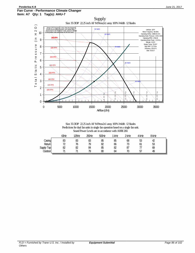
Penderlea K-8 June 21, 2017
FLD = Furnished by Trane U.S. Inc. / Installed by Others
Equipment Submittal Page 86 of 102
Fan Curve - Performance Climate Changer Item: A7 Qty: 1 Tag(s): AHU-7
6.
00
h
p
10
.0
0
hp
15
.0
0
hp
20
.0
0
hp
30
.0
0
hp
40
.0
0
hp
1000 RPM
1200 RPM
1400 RPM
1600 RPM
1800 RPM
2000 RPM
2200 RPM
2400 RPM2403 RPM
50 %WO
60 %WO
70 %WO
80 %WO
90 %WO
UnitSize: 22TF
Motor Frequency: 59.00Hz
Operating Airflow: 15800.00 cfm
Operating Static Pressure: 2.90 in H2O
Operating RPM: 1746.00
Operating Brake Power: 12.04 hp
Altitude: 0.00 ft
Design Temp: 70.00 F
Max BHP: 12.76 hp
Efficiency: 60.00 %
Date: 6/21/17
Design VFD frequency is less than line frequency. Ensure the air delivery system can handle being
pressurized to the Maximum static pressure detailedin the product data and shown on the fan curve.
0
1
2
3
4
5
6
7
8
9
10
0 5000 10000 15000 20000 25000 30000 35000
Supply Size 35 DDP 22.25 inch AF M Press2x1 array 100% Width 12 blades
To
tal
Sta
tic
Pr
es
su
re
(in
H2
O)
Airflow (cfm)
Size 35 DDP 22.25 inch AF M Press2x1 array 100% Width 12 bladesPredictions for dual fan units in single fan operation based on a single fan unit.
Sound Power Levels are in accordance with AHRI 260.
63Hz 125Hz 250Hz 500Hz 1 kHz 2 kHz 4 kHz 8 kHz
Casing 83 83 83 85 85 68 53 42Return 72 76 79 82 66 73 61 53
Supply Top 82 82 84 85 82 87 77 69Outdoor 71 71 79 80 64 70 57 49
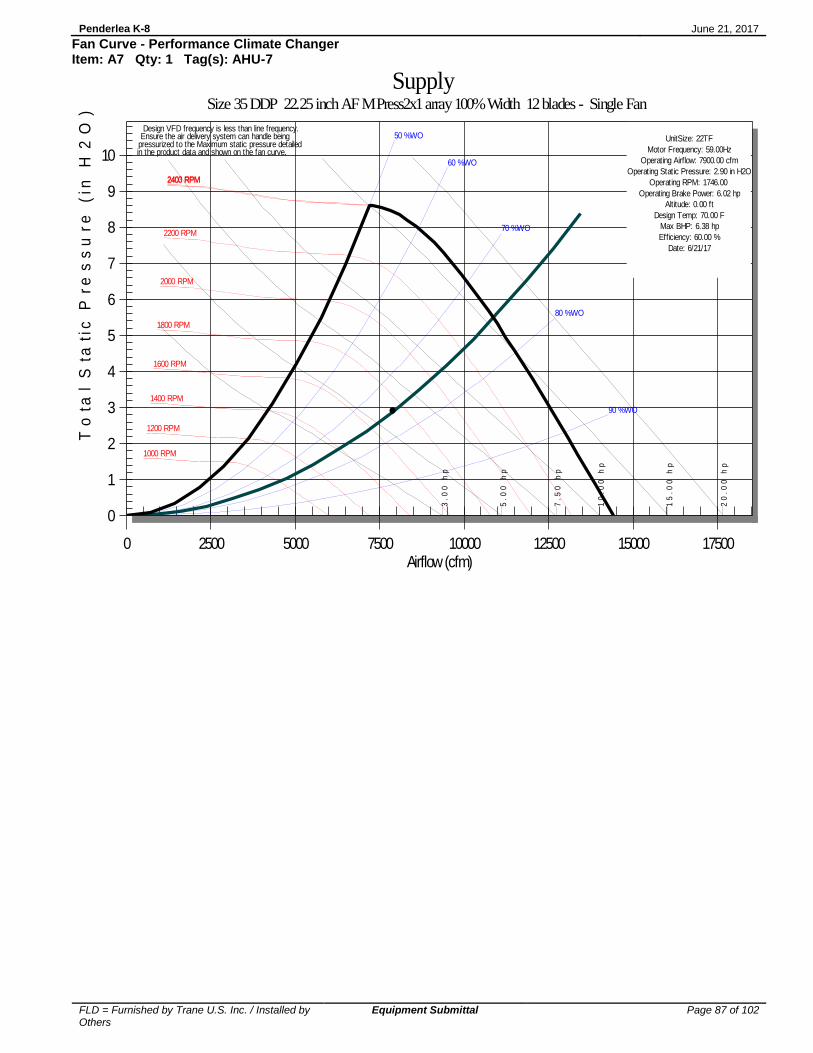
Penderlea K-8 June 21, 2017
FLD = Furnished by Trane U.S. Inc. / Installed by Others
Equipment Submittal Page 87 of 102
Fan Curve - Performance Climate Changer Item: A7 Qty: 1 Tag(s): AHU-7
3.
00
h
p
5.
00
h
p
7.
50
h
p
10
.0
0
hp
15
.0
0 h
p
20
.0
0 h
p
1000 RPM
1200 RPM
1400 RPM
1600 RPM
1800 RPM
2000 RPM
2200 RPM
2400 RPM2403 RPM
50 %WO
60 %WO
70 %WO
80 %WO
90 %WO
UnitSize: 22TF
Motor Frequency: 59.00Hz
Operating Airflow: 7900.00 cfm
Operating Static Pressure: 2.90 in H2O
Operating RPM: 1746.00
Operating Brake Power: 6.02 hp
Altitude: 0.00 ft
Design Temp: 70.00 F
Max BHP: 6.38 hp
Efficiency: 60.00 %
Date: 6/21/17
Design VFD frequency is less than line frequency. Ensure the air delivery system can handle being
pressurized to the Maximum static pressure detailedin the product data and shown on the fan curve.
0
1
2
3
4
5
6
7
8
9
10
0 2500 5000 7500 10000 12500 15000 17500
Supply Size 35 DDP 22.25 inch AF M Press2x1 array 100% Width 12 blades - Single Fan
To
tal
Sta
tic
Pre
ss
ure
(in
H2
O)
Airflow (cfm)

Penderlea K-8 June 21, 2017
FLD = Furnished by Trane U.S. Inc. / Installed by Others
Equipment Submittal Page 88 of 102
Fan Curve - Performance Climate Changer Item: A8 Qty: 1 Tag(s): AHU-8
1.
50
h
p
2.
00
h
p
3.
00
h
p
5.
00
h
p
7.
50
h
p
10
.0
0
hp
1400 RPM
1600 RPM
1800 RPM
2000 RPM
2200 RPM
2400 RPM
2600 RPM
2800 RPM
3000 RPM
3200 RPM
3400 RPM
3468 RPM
50 %WO
60 %WO
70 %WO
80 %WO
90 %WO
UnitSize: 16TR
Motor Frequency: 84.00Hz
Operating Airflow: 3100.00 cfm
Operating Static Pressure: 3.33 in H2O
Operating RPM: 2474.00
Operating Brake Power: 2.87 hp
Altitude: 0.00 ft
Design Temp: 70.00 F
Max BHP: 3.04 hp
Efficiency: 56.81 %
Date: 6/21/17
37
38
0
1
2
3
4
5
6
7
8
9
10
11
12
0 1000 2000 3000 4000 5000 6000 7000
Supply Size 6 DDP 16.5 inch AF M Press 80% Width 9 blades - Single Fan
To
tal
Sta
tic
Pr
es
su
re
(in
H2
O)
Airflow (cfm)
Size 6 DDP 16.5 inch AF M Press 80% Width 9 bladesSound Power Levels are in accordance with AHRI 260.
63Hz 125Hz 250Hz 500Hz 1 kHz 2 kHz 4 kHz 8 kHz
Casing 83 71 81 79 69 57 52 44Return 66 69 75 72 61 63 58 49
Supply Top 77 75 75 73 66 66 62 53Outdoor 64 64 75 70 59 59 54 45

Penderlea K-8 June 21, 2017
FLD = Furnished by Trane U.S. Inc. / Installed by Others
Equipment Submittal Page 89 of 102
Accessory - Performance Climate Changer Item: A1 - A8 Qty: 8 Tag(s): AHU-1, AHU-2, AHU-3, AHU-4, AHU-5, AHU-6, AHU-7, AHU-8
Base Detail
6"

Penderlea K-8 June 21, 2017
FLD = Furnished by Trane U.S. Inc. / Installed by Others
Equipment Submittal Page 90 of 102
Accessory - Performance Climate Changer Item: A1 - A8 Qty: 8 Tag(s): AHU-1, AHU-2, AHU-3, AHU-4, AHU-5, AHU-6, AHU-7, AHU-8
D (
Inte
rnal
6 48
59
61
A (
filter)
Com
ponent
Overload b
ox)
B (
coil,
hum
idifie
r)
D (
Exte
rnal S
tart
er,
VF
D, LV
box o
r
C (
UV
Lig
hts
)
483
484
48
61
59
61
8 48
10
48
12
48
66
61
77
82
61
61
17
48
14
48
21
48
87
61
87
61
95
64
66
52
156
64
48
128
25
48
30
48
35
48
95
109
64
64
115
64
40
50
48
57
48
141
64
64
141
64
80
56
100
58
120
58
156
64
170
197
64
64
48
89
48
56
Ext V
estible
)
Int V
estible
) F
(G
as H
eat
Sta
rter
or
E (
fan)
F (
Gas H
eat
VF
D)
48
N/A
48
48
48
N/A
N/A
N/A
100
48
48 90
48
51
48
54
108
63
74
79
48
105
61
48
58
100
48
60
115
84
84
92
48
170
93
153
140
125
48
66
48
66
115
118
48
66
136
92
106
112
48
70
48
77
156
48
77
156
138
138
N/A
48 93
179
48
101
48
101
180
153
167
194
VF
D
59
C (
TC
AC
)43
59
63
75
81
83
83
58
83
58
83
75
83
83
83
83
75
83
52
56
58
58
57
48
110
64
48
66
N/A
N/A83
48
48
48
48
48
48
48
48
48
48
48
48
48
48
48
48
50
48
110
64
48
66
N/A
N/A83
48
48
96
40 64
N/A
N/A
48 60
83
48
48
9635 64
N/A
N/A48
60
59
48
30
48
87
64
48
58
N/A
N/A83
48
25
48
77
64
48 51
N/A
N/A75
48
21
48
77
64
48
51
N/A
N/A
75
48
TA
LL
TA
LL
TA
LL
TA
LL
TA
LL
TA
LL
TA
LL
VF
D
LV
> 1
8 p
t or
UC
600
pt or
less)
G (
contr
ol box L
V 1
8
G (
contr
ol box H
V o
r36
13
contr
olle
r)
Com
ponent
All
Siz
es
N/A
N/A
N/A
N/A
N/A
N/A
N/A
N/A
N/A
N/A
N/A
N/A
N/A
N/A
N/A
67
67
76
80
88
96
96
105
105
113
129
B (
sta
ggere
d c
oil)
Ga
s h
ea
t
Acce
ss
do
or
F
E
Filt
er
mix
ing b
ox
Note
: A
t a m
inim
um
, th
ese c
lea
ran
ce d
imen
sio
ns a
re
reco
mm
ende
d o
n o
ne s
ide o
f th
e u
nit f
or
regula
r
serv
ice a
nd
main
tena
nce
. R
efe
r to
as-b
uilt
subm
itta
l
for
location
s o
f item
s s
uch
as f
ilter
access d
oo
rs,
coil,
pip
ing
conn
ection
s,
moto
r lo
ca
tions, etc
.
Suff
icie
nt cle
ara
nce m
ust
be
pro
vid
ed o
n a
ll sid
es o
f
un
it f
or
rem
ova
l of
pan
els
or
section
-to-s
ection
att
ach
ment.
C
lea
ran
ce f
or
sta
rters
, V
FD
s,
or
oth
er
hig
h-v
oltag
e d
evic
es m
ust
be
pro
vid
ed
pe
r N
EC
req
uirem
en
ts.
D
CB
A
Coil
UV
Lig
hts
or
TC
AC
Fa
n
Fa
n
D
E
Acce
ss
G
Serv
ice C
leara
nce
for
Contr
ol B
ox
EX
AM
PL
E U
NIT
- N
OT
CO
NF
IGU
RE
D A
S S
EL
EC
TE
D.

Penderlea K-8 June 21, 2017
FLD = Furnished by Trane U.S. Inc. / Installed by Others
Equipment Submittal Page 91 of 102
Accessory - Performance Climate Changer Item: A1 - A8 Qty: 8 Tag(s): AHU-1, AHU-2, AHU-3, AHU-4, AHU-5, AHU-6, AHU-7, AHU-8
D ± 1/16
H ± 1/8
STANDARD CONSTRUCTION
1. 100 % Synthetic White Un-Dyed Media
2. 10.0 Pleats Per Foot
3. Expanded Metal Pleat Supports
4. Moisture Resistant Beverage Board Frame
5. Double Wall Frame
NOTES
1. MERV 8-A Per ASHRAE 52.2-2007 Appendix J.
2. Final Resistance: 1/0" W.G.
3. Rated Velocity: 500 FPM
4. Class 2 Filter Per U.L. Standard 900
5. Maximum Operating Temperature: 225 DEG. F
MODEL NUMBER
RATED
AIR FLOW
CFM
INITIAL
RESISTANCE
IN. W.G.
MX40-STD2-217 10 X 20 X 2 9-1/2 X 19-1/2 X 1-3/4 700 0.29 4.7
MX40-STD2-220 12 X 20 X 2 11-1/2 X 19-1/2 X 1-3/4 840 0.29 5.5
MX40-STD2-210 12 X 24 X 2 11-3/8 X 23-3/8 X 1-3/4 1000 0.29 6.2
MX40-STD2-239 14 X 20 X 2 13-1/2 X 19-1/2 X 1-3/4 980 0.29 5.7
MX40-2TD2-241 14 X 25 X 2 13-1/2 X 24-1/2 X 1-3/4 1220 0.29 7.1
MX40-STD2-245 15 X 20 X 2 14-1/2 X 19-1/2 X 1-3/4 1050 0.29 6.2
MX40-STD2-201 16 X 20 X 2 15-1/2 X 19-1/2 X 1-3/4 1120 0.29 6.7
MX40-STD2-216 16 X 24 X 2 15-3/8 X 23-3/8 X 1-3/4 1340 0.29 8.0
MX40-STD2-202 16 X 24 X 2 15-1/2 X 24-1/2 X 1-3/4 1400 0.29 8.0
MX40-STD2-280 15 X 20 X 2 17-1/2 X 19-1/2 X 1-3/4 1250 0.29 7.8
MX40-STD2-212 18 X 24 X 2 17-3/8 X 23-3/8 X 1-3/4 1500 0.29 9.3
MX40-STD2-285 18 X 25 X 2 17-1/2 X 24-1/2 X 1-3/4 1570 0.29 9.7
MX40-STD2-203 20 X 20 X 2 19-1/2 X 19-1/2 X 1-3/4 1400 0.29 8.3
MX40-STD2-211 20 X 24 X 2 19-3/8 X 23-3/8 X 1-3/4 1670 0.29 9.9
MX40-STD2-204 20 X 25 X 2 19-1/2 X 24-1/2 X 1-3/4 1750 0.29 10.3
MX40-STD2-205 24 X 24 X 2 23-3/8 X 23-3/8 X 1-3/4 2000 0.29 11.7
MX40-STD2-225 25 X 25 X 2 24-1/2 X 24-1/2 X 1-3/4 2170 0.29 13.6
W ± 1/8
AIR FLOW
ACTUAL SIZE
IN. W X H X D
MEDIA AREA
SQ. FT.
NOMINAL SIZE
IN. W X H X D
EXPANDED
GRID BACKING

Penderlea K-8 June 21, 2017
FLD = Furnished by Trane U.S. Inc. / Installed by Others
Equipment Submittal Page 92 of 102
Accessory - Performance Climate Changer Item: A1 - A4 Qty: 4 Tag(s): AHU-1, AHU-2, AHU-3, AHU-4
INCLUDING REMOTE DISCONNECTS AND
AVERTISSEMENT
ADVERTENCIA
NE PAS RESPECTER CES MESURES DE
FOLLOW LOCK OUT AND TAG PROCEDURES
BEFORE SERVICING. INSURE THAT ALL
MOTOR CAPACITORS HAVE DISCHARGED
STORED VOLTAGE. UNITS WITH VARIABLE
INSTRUCTIONS FOR CAPACITOR DISCHARGE.
SERVICING COULD RESULT IN DEATH OR
INSTRUCTIONS DE L'ENTRAÎNEMENT POUR
VITESSE VARIABLE, SE REPORTER AUX
DÉCHARGÉS. DANS LE CAS D'UNITÉS
LES CONDENSATEURS DES MOTEURS SONT
TOUTE INTERVENTION. VÉRIFIER QUE TOUS
VERROUILLAGE ET DES ÉTIQUETTES AVANT
OUVRIR LES SECTIONNEURS À DISTANCE,
PRÉCAUTION PEUT ENTRAÎNER DES
BLESSURES GRAVES POUVANT ÊTRE
DÉCHARGER LES CONDENSATEURS.
MORTELLES.
TENSION DANGEREUSE!
SPEED DRIVE, REFER TO DRIVE
FAILURE TO DO THE ABOVE BEFORE
COMPORTANT DES ENTRAÎNEMENTS À
PUIS SUIVRE LES PROCÉDURES DE
COUPER TOUTES LES TENSIONS ET
SERIOUS INJURY.
WARNING
DISCONNECT ALL ELECTRIC POWER
HAZARDOUS VOLTAGE!
CONSULTE LAS INSTRUCCIONES PARA LA
DIRECCIÓN DE VELOCIDAD VARIABLE,
PARA LAS UNIDADES CON EJE DE
SERVICIO. ASEGÚRESE DE QUE TODOS
ETIQUETADO ANTES DE PROCEDER AL
SIGA LOS PROCEDIMIENTOS DE CIERRE Y
INCLUSO LAS DESCONEXIONES REMOTAS Y
O SERIAS LESIONES PERSONALES.
INDICADO, PODRÍA OCASIONAR LA MUERTE
EL NO REALIZAR LO ANTERIORMENTE
DESCARGA DEL CONDENSADOR.
LOS CAPACITORES DEL MOTOR HAYAN
iVOLTAJE PELIGROSO!
DESCARGADO EL VOLTAJE ALMACENADO.
DESCONECTE TODA LA ENERGÍA ELÉCTRICA,
FAILURE TO DO SO MAY CAUSE DAMAGE TO THE
UNIT TERMINALS ARE NOT DESIGNED TO ACCEPT
N'UTILISER QUE DES CONDUCTEURS EN CUIVRE!
LES BORNES DE L'UNITÉ NE SONT PAS CONÇUES
POUR RECEVOIR D'AUTRES TYPES DE CONDUCTEURS.
L'UTILISATION DE TOUT AUTRE CONDUCTEUR PEUT
SI NO LO HACE, PUEDE OCASIONAR DAÑO AL EQUIPO.
PARA ACEPTAR OTROS TIPOS DE CONDUCTORES.
LAS TERMINALES DE LA UNIDAD NO ESTÁN DISEÑADAS
¡UTILICE ÚNICAMENTE CONDUCTORES DE COBRE!
ENDOMMAGER L'ÉQUIPEMENT.
PRECAUCIÓN
OTHER TYPES OF CONDUCTORS.
EQUIPMENT.
ATTENTION
USE COPPER CONDUCTORS ONLY!
CAUTION
GR
N
WH
T
BLK
GR
N
WH
T
BL
K
GR
N
WH
T
BL
K
UV LIGHT
BLK
GR
N
WH
T
BL
K
GR
N
WH
T
BL
K
WH
T
GR
N
DASHED LINES INDICATE RECOMMENDED FIELD WIRING BY OTHERS.
UV LAMPS WILL NEED TO BE INSTALLED IN LAMP FIXTURES BEFORE
LAMPS ARE DESIGENED TO CONTROL MICROBIAL GROWTH ON
UV LAMPS WILL NOT REMOVE AIRBORNE CONTAMINANTS.
AND ON. REPLACE LAMPS ONCE PER YEAR.
COIL AND DRAIN PAN SURFACES. DO NOT CYCLE LAMPS OFF
UNIT START UP.
GRN
GRN
SWITCH BOX
WHT
GRN
BLK
BLK
GRN
GRN
WHT
BLK
BLK
WHT
GRN
WHT
6
5
4
3
2
1 7
8
10
GRN
11
WHT
12
BLK
13
GRN 9
HN
G
HN
G
CUSTOMER SUPPLIED 120VAC
POWER
5
4
LEGEND
JACK - UV LIGHTS
DOOR KILL SWITCH FOR UV LIGHTS
DESCRIPTION
PLUG - UV LIGHTS
MAIN EXTERNAL UV LIGHT SWITCH
DEVICE
DESIGNATION
1J1
1P1 to 1P3
3S1
3S2
1
2
NOTES:
ALL FIELD WIRING MUST BE IN ACCORDANCE WITH THE NATIONAL
ELECTRICAL CODE (NEC), STATE AND LOCAL REQUIREMENTS. OTHER
COUNTRIES APPLICABLE NATIONAL AND/OR LOCAL REQUIREMENTS
SHALL APPLY. FIELD CONDUCTORS SHALL HAVE INSULATION
INSULATION RATING NOT LESS THAN 600V.
SWITCH CLOSES WHEN ACCESS DOORS ARE SHUT.
CONNECTORS REQUIRED
FOR SHIPPING SPLITS
TO ADDITIONAL LIGHT
FIXTURES (IF REQUIRED)
TO ADDITIONAL ROWS OF
LIGHT FIXTURES (IF
REQUIRED)
ADDITIONAL SWITCHES (IF
REQUIRED) WIRED IN SERIES
3
3
EXTERNAL
3S1
3S2
1 2

Penderlea K-8 June 21, 2017
FLD = Furnished by Trane U.S. Inc. / Installed by Others
Equipment Submittal Page 93 of 102
Accessory - Performance Climate Changer Item: A1 - A4 Qty: 4 Tag(s): AHU-1, AHU-2, AHU-3, AHU-4
Limit Switch Notes:
1. Parts Must Have Trane Part Number With Bar Code per ES.
2. All Dimensions Are Reference Dimensions Unless Otherwise Noted.
3. Replace 2 Mounting Screws with Pan Head Combination Drive Sheet Metal Screws, 18-8 Stainless Steel, #6 Size ½” Length.

Penderlea K-8 June 21, 2017
FLD = Furnished by Trane U.S. Inc. / Installed by Others
Equipment Submittal Page 94 of 102
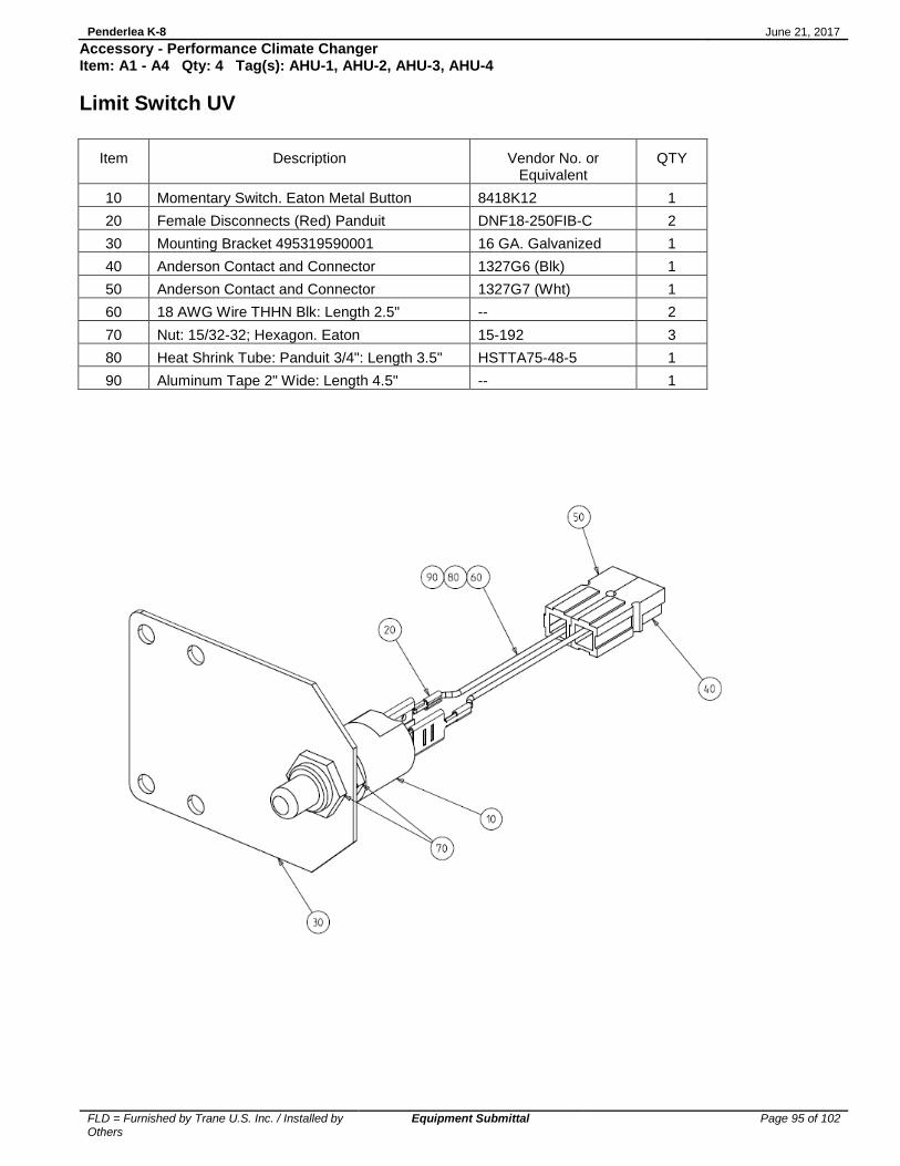
Penderlea K-8 June 21, 2017
FLD = Furnished by Trane U.S. Inc. / Installed by Others
Equipment Submittal Page 95 of 102
Accessory - Performance Climate Changer Item: A1 - A4 Qty: 4 Tag(s): AHU-1, AHU-2, AHU-3, AHU-4
Limit Switch UV
Item
Description
Vendor No. or Equivalent
QTY
10 Momentary Switch. Eaton Metal Button 8418K12 1
20 Female Disconnects (Red) Panduit DNF18-250FIB-C 2
30 Mounting Bracket 495319590001 16 GA. Galvanized 1
40 Anderson Contact and Connector 1327G6 (Blk) 1
50 Anderson Contact and Connector 1327G7 (Wht) 1
60 18 AWG Wire THHN Blk: Length 2.5" -- 2
70 Nut: 15/32-32; Hexagon. Eaton 15-192 3
80 Heat Shrink Tube: Panduit 3/4": Length 3.5" HSTTA75-48-5 1
90 Aluminum Tape 2" Wide: Length 4.5" -- 1

Penderlea K-8 June 21, 2017
FLD = Furnished by Trane U.S. Inc. / Installed by Others
Equipment Submittal Page 96 of 102
Accessory - Performance Climate Changer Item: A1 - A4, A7 Qty: 5 Tag(s): AHU-1, AHU-2, AHU-3, AHU-4, AHU-7
1A
2A
T3-A
T1-A
T2-AM
2 FAN
3A3A,6A,9A,12A,15A,18A
2A,5A,8A,11A,14A,17A
1A,4A,7A,10A,13A,16A
3
2
1
1PDB3
L2
L3
L1
5
6
5
T1
T2
T3
L1
L2
L3
1MMP-A
M
T1
T2
T3
L1
L2
L3
OPTION
M
T1
T2
T3
L1
L2
L3
M
T1
T2
T3
L1
L2
L3
M
T1
T2
T3
L1
L2
L3
M
T1
T2
T3
L1
L2
L3
4 FANOPTION
6 FANOPTION
1TB14-1
1TB14-2 1MMP-A 1MMP-B 1MMP-C 1MMP-D 1MMP-E 1MMP-F
30A 31A 32A 33A 34A 35A 36A
13 14
(43) (44)
13 14
(43) (44)
13 14
(43) (44)
13 14
(43) (44)
13 14
(43) (44)
13 14
(43) (44)
2 FAN OPTION
4 FAN OPTION
6 FAN OPTION
4A
5A
T3-B
T1-B
T2-B
6A
1MMP-B
7A
8A
T3-C
T1-C
T2-C
9A
1MMP-C
10A
11A
T3-D
T1-D
T2-D
12A
1MMP-D
13A
14A
T3-E
T1-E
T2-E
15A
1MMP-E
16A
17A
T3-F
T1-F
T2-F
18A
1MMP-F
3B1-F
3B1-E
3B1-D
3B1-C
3B1-B
3B1-A
SIZE
LINE
12 - 24
1 - 10, AND
EXTENSION
1 - 6
2/0 - 6
CONDUCTOR
150
200
J
150
200
T
65KA
65KA
SCCR
G, H, I
B, C
WIRE CLASS
30
30
CC
60
60
G
30
100
RK5
100
200
RK1
MAX FUSE SIZE
APPROPRIATE UPSTREAM FUSING FOR SHORT CIRCUIT CURRENT RATING
Panel is 65kA SCCR for 200V, 230V and 460V when the above upstream fusing is used.
INCLUDING REMOTE DISCONNECTS AND
AVERTISSEMENT
ADVERTENCIA
NE PAS RESPECTER CES MESURES DE
FOLLOW LOCK OUT AND TAG PROCEDURES
BEFORE SERVICING. INSURE THAT ALL
MOTOR CAPACITORS HAVE DISCHARGED
STORED VOLTAGE. UNITS WITH VARIABLE
INSTRUCTIONS FOR CAPACITOR DISCHARGE.
SERVICING COULD RESULT IN DEATH OR
INSTRUCTIONS DE L'ENTRA?NEMENT POUR
VITESSE VARIABLE, SE REPORTER AUX
D?CHARG?S. DANS LE CAS D'UNIT?S
LES CONDENSATEURS DES MOTEURS SONT
TOUTE INTERVENTION. V?RIFIER QUE TOUS
VERROUILLAGE ET DES ?TIQUETTES AVANT
OUVRIR LES SECTIONNEURS ? DISTANCE,
PR?CAUTION PEUT ENTRA?NER DES
BLESSURES GRAVES POUVANT ?TRE
D?CHARGER LES CONDENSATEURS.
MORTELLES.
TENSION DANGEREUSE!
SPEED DRIVE, REFER TO DRIVE
FAILURE TO DO THE ABOVE BEFORE
COMPORTANT DES ENTRA?NEMENTS ?
PUIS SUIVRE LES PROC?DURES DE
COUPER TOUTES LES TENSIONS ET
SERIOUS INJURY.
WARNING
DISCONNECT ALL ELECTRIC POWER
HAZARDOUS VOLTAGE!
CONSULTE LAS INSTRUCCIONES PARA LA
DIRECCI?N DE VELOCIDAD VARIABLE,
PARA LAS UNIDADES CON EJE DE
SERVICIO. ASEG?RESE DE QUE TODOS
ETIQUETADO ANTES DE PROCEDER AL
SIGA LOS PROCEDIMIENTOS DE CIERRE Y
INCLUSO LAS DESCONEXIONES REMOTAS Y
O SERIAS LESIONES PERSONALES.
INDICADO, PODR?A OCASIONAR LA MUERTE
EL NO REALIZAR LO ANTERIORMENTE
DESCARGA DEL CONDENSADOR.
LOS CAPACITORES DEL MOTOR HAYAN
iVOLTAJE PELIGROSO!
DESCARGADO EL VOLTAJE ALMACENADO.
DESCONECTE TODA LA ENERG?A EL?CTRICA,
FAILURE TO DO SO MAY CAUSE DAMAGE TO THE
UNIT TERMINALS ARE NOT DESIGNED TO ACCEPT
N'UTILISER QUE DES CONDUCTEURS EN CUIVRE!
LES BORNES DE L'UNIT? NE SONT PAS CON?UES
POUR RECEVOIR D'AUTRES TYPES DE CONDUCTEURS.
L'UTILISATION DE TOUT AUTRE CONDUCTEUR PEUT
SI NO LO HACE, PUEDE OCASIONAR DA?O AL EQUIPO.
PARA ACEPTAR OTROS TIPOS DE CONDUCTORES.
LAS TERMINALES DE LA UNIDAD NO EST?N DISE?ADAS
?UTILICE ?NICAMENTE CONDUCTORES DE COBRE!
ENDOMMAGER L'?QUIPEMENT.
PRECAUCI?N
OTHER TYPES OF CONDUCTORS.
EQUIPMENT.
ATTENTION
USE COPPER CONDUCTORS ONLY!
CAUTION
PH
PH
PH
PH
PH
PH
ATTACH GROUND OR EQUIPMENT GROUND.
MINIMUM CIRCUIT AMPACITY, MAXIMUM FUSE SIZE, AND DISCONNECT
SIZE ARE CALCULATED BASED ON THE INVERTER INPUT LINE CURRENTS
PER ARTICLE 430-2 OF THE NATIONAL ELECTRICAL CODE.
DASHED LINES INDICATE RECOMMENDED FIELD WIRING BY OTHERS.
PHANTOM LINES INDICATE CONTROL OPTION.
3
1
NOTES:
ALL FIELD WIRING MUST BE IN ACCORDANCE WITH THE NATIONAL
ELECTRICAL CODE (NEC), STATE AND LOCAL REQUIREMENTS. OTHER
COUNTRIES APPLICABLE NATIONAL AND/OR LOCAL REQUIREMENTS
SHALL APPLY. FIELD CONDUCTORS SHALL HAVE INSULATION
RATING NOT LESS THAN 600V; COPPER CONDUCTORS ONLY.
2
AUXILIARY CONTACTS WILL BE OPEN WHEN THE MMP IS IN THE "OFF"
OR "TRIPPED" STATE.
MOTORS (FAN ARRAY)
TERMINAL STRIP CONTROL CIRCUIT
POWER DISTRIBUTION BLOCK
3B1-A TO 3B1-F
DEVICE
DESIGNATION
1TB14
1PDB3
DESCRIPTION
LEGEND
DEVICE PREFIX LOCATION CODE
LOCATION
AIR HANDLER SECTION
LOW VOLTAGE PANEL (UNIT SCHEMATIC)
HIGH VOLTAGE PANEL
3
2
1
AREA
CUSTOMER
SUPPLIED
POWER
GND
MANUAL MOTOR PROTECTORS (FAN ARRAY)1MMP-A TO 1MMP-F
30008
PANEL IS RATED FOR USE WITH WYE POWER SYSTEMS NOT TO EXCEED
600V.4

Penderlea K-8 June 21, 2017
FLD = Furnished by Trane U.S. Inc. / Installed by Others
Equipment Submittal Page 97 of 102
Accessory - Performance Climate Changer Trap Schedule Item: A1 - A8 Qty: 8 Tag(s): AHU-1, AHU-2, AHU-3, AHU-4, AHU-5, AHU-6, AHU-7, AHU-8
Unit Tag(s)
Unit Size
Entering Ext. Static Pressure (in H2O)
Discharge Ext. Static Pressure (in H2O)
Drain pan Section Location
Recommended Trap Dimensions1
Selected Baserail
Height (in)1
H (in)
J (in)
L (in)
AHU-12 Unit size 35 1.250 1.250
Coil section [4]
3.933 1.967 7.150 6.000
AHU-22 Unit size 35 1.250 1.250
Coil section [4]
3.986 1.993 7.230 6.000
AHU-32 Unit size 35 1.250 1.250
Coil section [4]
4.158 2.079 7.487 6.000
AHU-42 Unit size 35 1.250 1.250
Coil section [4]
4.162 2.081 7.493 6.000
AHU-52 Unit size 14 0.625 0.625
Coil section [4]
3.581 1.790 6.371 6.000
AHU-62 Unit size 12 0.625 0.625
Coil section [4]
3.504 1.752 6.255 6.000
AHU-72 Unit size 35 0.625 0.625
Coil section [4]
3.422 1.711 6.384 6.000
AHU-82 Unit size 6 0.625 0.625
Coil section [2]
3.720 1.860 6.580 6.000
1 To ensure proper condensate trapping the field installed housekeeping pad height is the responsibility of the
contractor. 2 The external static pressure used for fan selection was assumed to be divided 50% to entering duct external static
pressure and 50% discharge external static pressure.
H
J
L
Drain pan trapping for section
under negative pressure
L = H + J + pipe diameter where:
H = 1 inch for each inch of negative
pressure (loaded filters) plus 1 inch
J = 12 H
Drain pan trapping for section
under positive pressure
L = H + J + pipe diameter where:
H = 1/2 inch (minimum)
J = 12 inch plus the unit positive static pressure at coil discharge (loaded
filters)

Penderlea K-8 June 21, 2017
FLD = Furnished by Trane U.S. Inc. / Installed by Others
Equipment Submittal Page 98 of 102
Accessory - Performance Climate Changer Filter Schedule Item: A1 - A8 Qty: 8 Tag(s): AHU-1, AHU-2, AHU-3, AHU-4, AHU-5, AHU-6, AHU-7, AHU-8
Unit Tag(s)
Unit Size
Filter Location
Filter Arrangement
Filter Depth
Filter Type
MERV Rating
Filter Quantity
Filter Size
AHU-1 Unit size 35 Air mixing section [1]
- 2in. filter frame Pleated media
- run set MERV 8
6 18
16in.x20in. 16in.x25in.
AHU-2 Unit size 35 Air mixing section [1]
- 2in. filter frame Pleated media
- run set MERV 8
6 18
16in.x20in. 16in.x25in.
AHU-3 Unit size 35 Air mixing section [1]
- 2in. filter frame Pleated media
- run set MERV 8
6 18
16in.x20in. 16in.x25in.
AHU-4 Unit size 35 Air mixing section [1]
- 2in. filter frame Pleated media
- run set MERV 8
6 18
16in.x20in. 16in.x25in.
AHU-5 Unit size 14 Air mixing section [1]
- 2in. filter frame Pleated media
- run set MERV 8
4 2
20in.x20in. 20in.x25in.
AHU-6 Unit size 12 Air mixing section [1]
- 2in. filter frame Pleated media
- run set MERV 8 6 20in.x20in.
AHU-7 Unit size 35 Air mixing section [1]
- 2in. filter frame Pleated media
- run set MERV 8
6 18
16in.x20in. 16in.x25in.
AHU-8 Unit size 6 Air mixing section [1]
- 2in. filter frame Pleated media
- run set MERV 8 4 16in.x20in.

Penderlea K-8 June 21, 2017
FLD = Furnished by Trane U.S. Inc. / Installed by Others
Equipment Submittal Page 99 of 102
Field Wiring - Performance Climate Changer MCA MOP Schedule Item: A1 - A8 Qty: 8 Tag(s): AHU-1, AHU-2, AHU-3, AHU-4, AHU-5, AHU-6, AHU-7, AHU-8
Unit Tag(s) Circuit Circuit Description Voltage/Phase/Hz MCA (A) MOP (A)
AHU-1, AHU-2
1 Supply fan motor(s)
460/3/60 28.13 40.00
2 UV lights 1 115/1/60 3.85 15.00
AHU-3, AHU-4
1 Supply fan motor(s)
460/3/60 34.65 50.00
2 UV lights 1 115/1/60 3.85 15.00
AHU-5 1 Supply fan motor(s)
460/3/60 15.63 25.00
AHU-6, AHU-8
1 Supply fan motor(s)
460/3/60 8.38 15.00
AHU-7 1 Supply fan motor(s)
460/3/60 28.13 40.00

Penderlea K-8 June 21, 2017
FLD = Furnished by Trane U.S. Inc. / Installed by Others
Equipment Submittal Page 100 of 102

Penderlea K-8 June 21, 2017
FLD = Furnished by Trane U.S. Inc. / Installed by Others
Equipment Submittal Page 101 of 102

Penderlea K-8 June 21, 2017
FLD = Furnished by Trane U.S. Inc. / Installed by Others
Equipment Submittal Page 102 of 102
Field Installed Options - Part/Order Number Summary
This is a report to help you locate field installed options that arrive at the jobsite. This report provides part or order numbers for each field installed option, and references it to a specific product tag. It is NOT intended as a bill of material for the job.
Product Family - Performance Climate Changer
Item Tag(s) Qty Description Model Number
A1 AHU-1 1 Performance Climate Changer ( CSAA ) CSAA035UA
A2 AHU-2 1 Performance Climate Changer ( CSAA ) CSAA035UA
A3 AHU-3 1 Performance Climate Changer ( CSAA ) CSAA035UA
A4 AHU-4 1 Performance Climate Changer ( CSAA ) CSAA035UA
A5 AHU-5 1 Performance Climate Changer ( CSAA ) CSAA014UA
A6 AHU-6 1 Performance Climate Changer ( CSAA ) CSAA012UA
A7 AHU-7 1 Performance Climate Changer ( CSAA ) CSAA035UA
A8 AHU-8 1 Performance Climate Changer ( CSAA ) CSAA006UA
Field Installed Option Description Part/Ordering Number
Pleated media - run set