Embed Size (px)
Citation preview
STEELHEAD MARINE: CT3500 1
CT3500 SWL : 16ft – 3500lbs
Owner’s Operation, Installation &
Maintenance Manual
STEELHEAD MARINE: CT3500 2
Table of Contents
Yacht Crane Assembly Drawing………………………………………………… 4
Yacht Standpipe Mount Assembly Drawing…...…………………………...……5
Required Equipment & Tools……………………………………………………….6
Supplied Equipment List……………………………………………………….6
Hydraulic & Electrical Connections………………………………………………..7
Completing & Testing Installation………………………………………………….8
Operating Instructions…………………………………………………………..……9
Warning review before operation………………………………..…………….9
Operating Instructions…………………………………………………...…………...9
Manual Control……………………………………………….………….…..……….11
Pendant Control………………………………………………………...……………12
Reach Table and Crane Storage………………………………….……………….13 Linear Winch Assembly and LED Light……………………….……...………….14 Crane Maintenance………………………………………………….……………….17 Hydraulic System Components.………………………………….……………….18 Troubleshooting………………….………………………………….……………….19 Specifications…………………….………………………………….……………….20
Electrical System………………………………………………………………20
Equipment Dimensions………………………………………………………..20
Warranty……………………………………………………………………………….21
Appendix
Hydraulic Schematic……………………………………….…………..APPENDIX A
Crane Electrical Schematic…………………………………………...APPENDIX B
Manual Override Control Manifold Manual………………………...APPENDIX C
STEELHEAD MARINE: CT3500 3
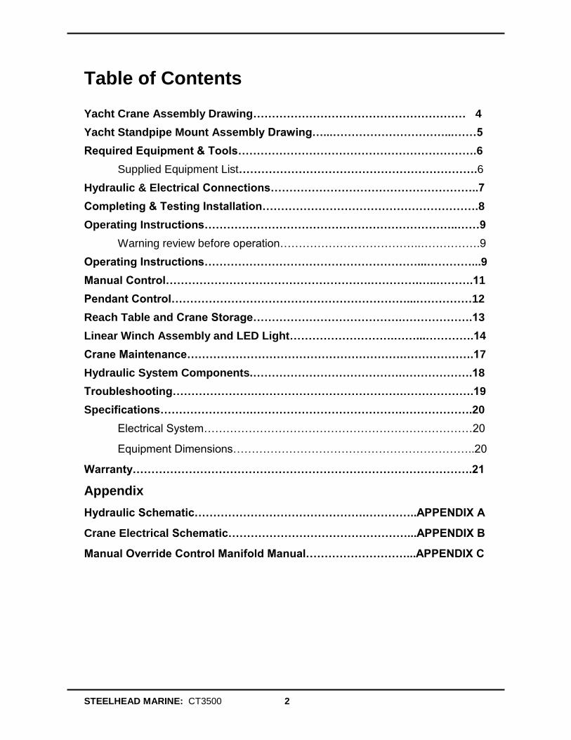
Notice to Boat Manufacturer or Installer
Throughout this publication, Warnings and Cautions accompanied by the International
Hazard Symbol is used to alert the manufacturer or installer to special instructions concerning a particular service or operation that may be hazardous if performed incorrectly or carelessly. Observe Them Carefully! These “safety alerts” alone, cannot eliminate the hazards that they signal. Strict compliance to these special instructions when performing the installation and maintenance plus “common sense” operation are major accident prevention measures.
Immediate hazards which WILL result in severe
personal injury or death.
Hazards or unsafe practices, which COULD result in severe personal injury or death.
Hazards or unsafe practices, which COULD result in minor injury or product or property damage.
Information, which is important to proper installation Or maintenance but is not hazard-related.
DANGER
WARNING
CAUTION
NOTICE
STEELHEAD MARINE: CT3500 4
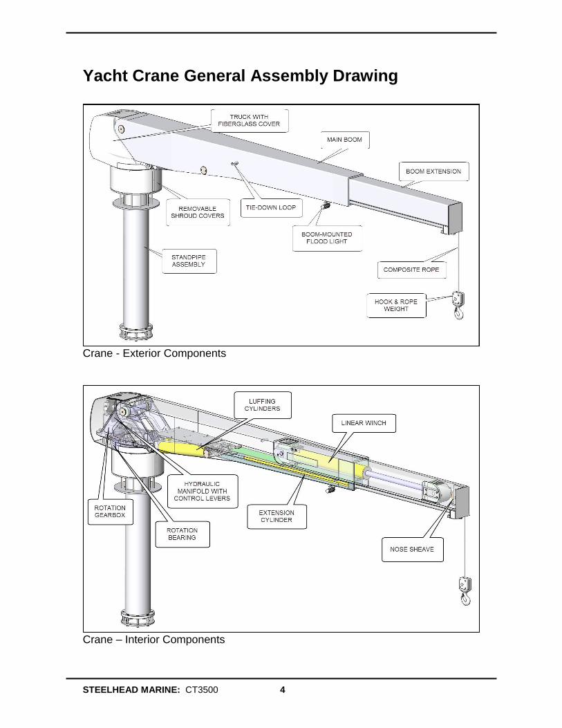
Yacht Crane General Assembly Drawing
Crane - Exterior Components
Crane – Interior Components
STEELHEAD MARINE: CT3500 5
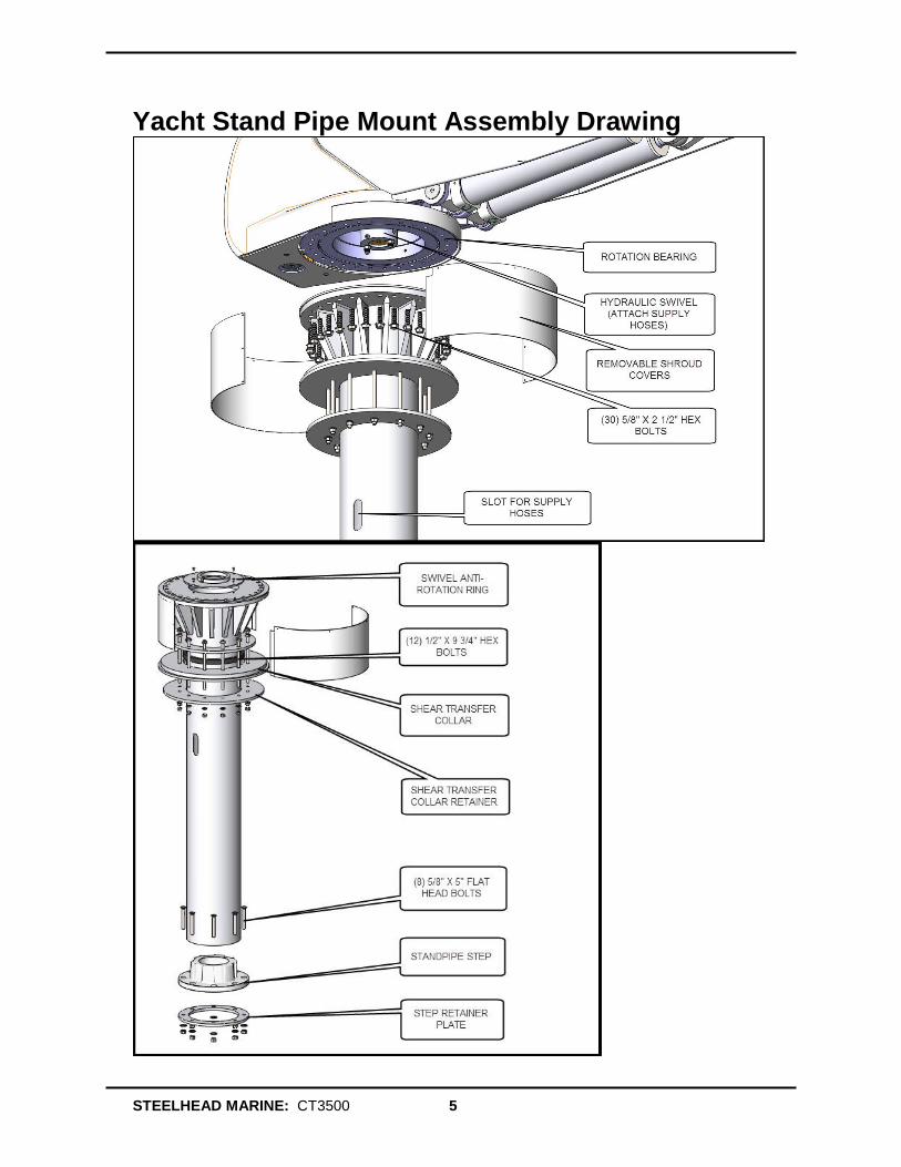
Yacht Stand Pipe Mount Assembly Drawing
STEELHEAD MARINE: CT3500 6
Required Equipment & Tools This section describes the equipment and tools needed or recommended for the yacht crane installation. Supplied Equipment List Your yacht crane comes with the following standard equipment:
Crane assembly, complete with:
bearing assembly installed
hydraulic and electrical system installed
composite rope, hook and weight assembly installed
(28) 5/8in 316 Stainless Steel (5/8-11 UNC ) mounting bolts and washers
360 degree rotary swivel c/w two male #8 MJIC connections
360 degree 3-contact electrical swivel
4 function, SCORPION hand-held pendant control (wired remote control)
Crane hydraulic control manifold with manual override controls (installed in
crane)
Owner's Handbook and Installation Manual
STEELHEAD MARINE: CT3500 7
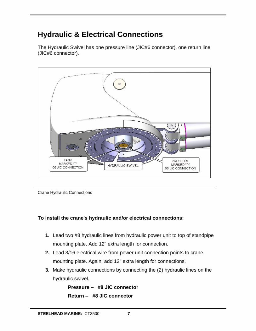
Hydraulic & Electrical Connections The Hydraulic Swivel has one pressure line (JIC#6 connector), one return line (JIC#6 connector).
Crane Hydraulic Connections
To install the crane's hydraulic and/or electrical connections:
1. Lead two #8 hydraulic lines from hydraulic power unit to top of standpipe
mounting plate. Add 12" extra length for connection.
2. Lead 3/16 electrical wire from power unit connection points to crane
mounting plate. Again, add 12" extra length for connections.
3. Make hydraulic connections by connecting the (2) hydraulic lines on the
hydraulic swivel.
Pressure – #8 JIC connector
Return – #8 JIC connector
STEELHEAD MARINE: CT3500 8
4. Complete electrical connections, and use heat shrink to seal connections
from corrosion.
5. Complete hydraulic and electrical connections at ship.
Completing & Testing Installation To complete and test the installation of the crane: 1. Lower crane onto mounting plate, ensuring that the hydraulic swivel fits
correctly into the retaining notch in center of mounting plate.
2. Install mounting bolts and torque to recommended values (see below).
3. Test crane as follows:
Turn breakers on momentarily.
Ensure power unit turns on.
Check all wiring.
Check hydraulic source and ensure correct pressure from pressure port.
Turn on control breaker.
5. When systems are confirmed correct, recheck oil level in reservoir in HPU and refill to proper level.
6. Use Tef-Gel where stainless screws contact painted surfaces to prevent paint blistering and corrosion.
7. During shipment, air may have collected in hydraulic system. To bleed, operate all boom functions through their full travel capacity 3 or 4 times, using pendant hand control. This will remove any air in the system.
8. Recheck oil level in reservoir to ensure level has been maintained. Bolt Torque Recommendations 1. Use thread lubricant (moly disulfide grease) on threads before beginning to
torque bolts.
2. Apply torque of 30 ft-lb in a cross or star pattern.
3. Apply final torque of (70-80 ft-lb) using the same order.
STEELHEAD MARINE: CT3500 9
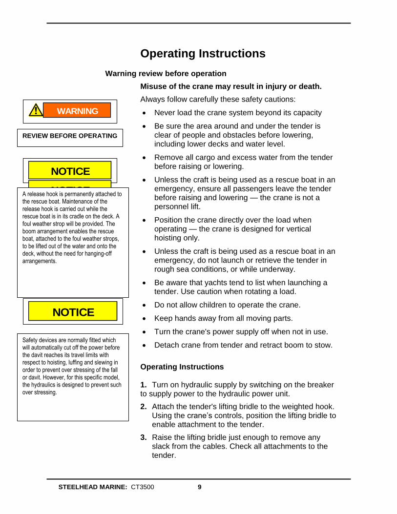
Operating Instructions Warning review before operation
Misuse of the crane may result in injury or death.
Always follow carefully these safety cautions:
Never load the crane system beyond its capacity
Be sure the area around and under the tender is clear of people and obstacles before lowering, including lower decks and water level.
Remove all cargo and excess water from the tender before raising or lowering.
Unless the craft is being used as a rescue boat in an emergency, ensure all passengers leave the tender before raising and lowering — the crane is not a personnel lift.
Position the crane directly over the load when operating — the crane is designed for vertical hoisting only.
Unless the craft is being used as a rescue boat in an emergency, do not launch or retrieve the tender in rough sea conditions, or while underway.
Be aware that yachts tend to list when launching a tender. Use caution when rotating a load.
Do not allow children to operate the crane.
Keep hands away from all moving parts.
Turn the crane's power supply off when not in use.
Detach crane from tender and retract boom to stow.
Operating Instructions
1. Turn on hydraulic supply by switching on the breaker to supply power to the hydraulic power unit.
2. Attach the tender's lifting bridle to the weighted hook. Using the crane’s controls, position the lifting bridle to enable attachment to the tender.
3. Raise the lifting bridle just enough to remove any slack from the cables. Check all attachments to the tender.
WARNING
REVIEW BEFORE OPERATING
NOTICE
NOTICE A release hook is permanently attached to
the rescue boat. Maintenance of the release hook is carried out while the rescue boat is in its cradle on the deck. A foul weather strop will be provided. The boom arrangement enables the rescue boat, attached to the foul weather strops, to be lifted out of the water and onto the deck, without the need for hanging-off arrangements.
NOTICE
Safety devices are normally fitted which will automatically cut off the power before the davit reaches its travel limits with respect to hoisting, luffing and slewing in order to prevent over stressing of the fall or davit. However, for this specific model, the hydraulics is designed to prevent such over stressing.
STEELHEAD MARINE: CT3500 10
4. Remove the tender's attachments to the deck, and ensure the tender's drain plug is installed.
5. Attach the handling lines to the bow and stern of the tender.
6. Raise the tender high enough to clear all deck obstructions and railings.
7. Rotate the load outboard, controlling the tender position with bow and stern lines.
8. Lower the load to the water. Pay out enough cable so that the tender does not load the cable and crane as it rides waves or swells.
9. Using the load-handling lines, pull the tender to a point near the vessel where it may be boarded. Disconnect the lifting bridle from the tender.
10. Secure the weighted hook so that it does not swing into the side of the vessel.
STEELHEAD MARINE: CT3500 11
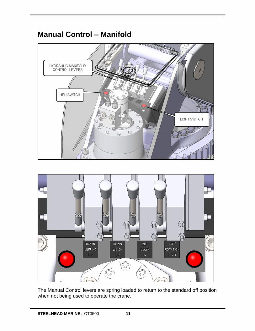
Manual Control – Manifold
The Manual Control levers are spring loaded to return to the standard off position when not being used to operate the crane.
STEELHEAD MARINE: CT3500 12
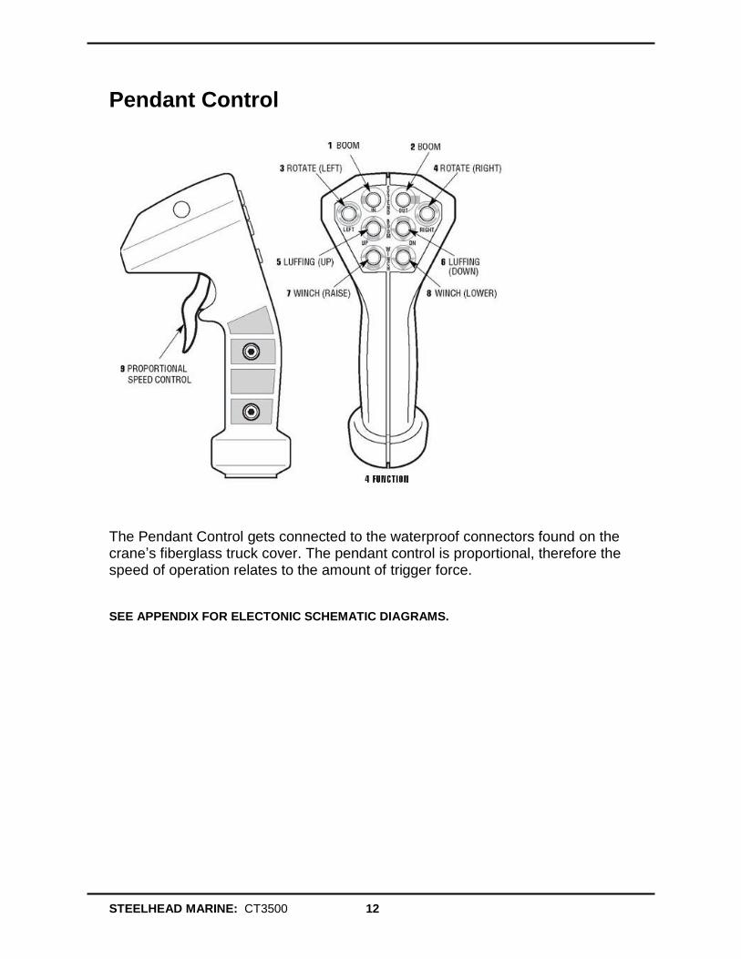
Pendant Control
The Pendant Control gets connected to the waterproof connectors found on the crane’s fiberglass truck cover. The pendant control is proportional, therefore the speed of operation relates to the amount of trigger force.
SEE APPENDIX FOR ELECTONIC SCHEMATIC DIAGRAMS.
STEELHEAD MARINE: CT3500 13
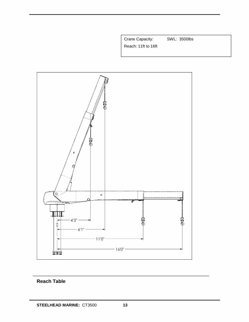
Reach Table
Crane Capacity: SWL: 3500lbs
Reach: 11ft to 16ft
STEELHEAD MARINE: CT3500 14
Crane Storage
To properly store the crane after use :
1. Fully retract the boom.
2. Rotate Crane to desired position.
3. Luff crane to horizontal position.
4. Disconnect Control and store in dry heated area of the vessel.
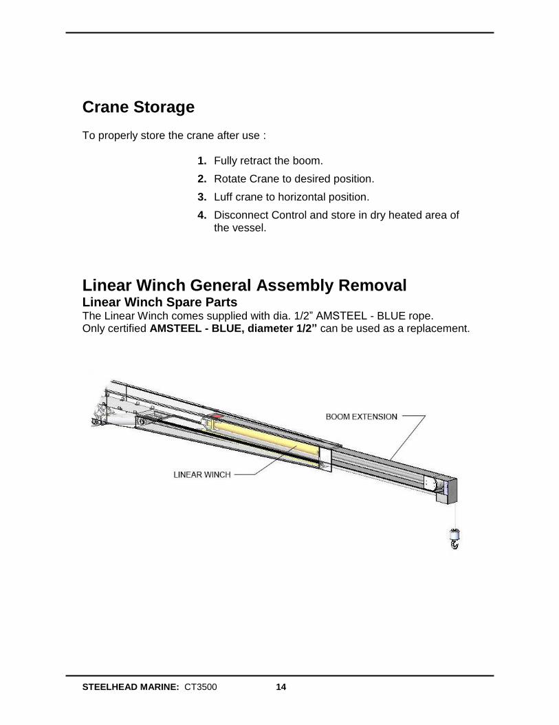
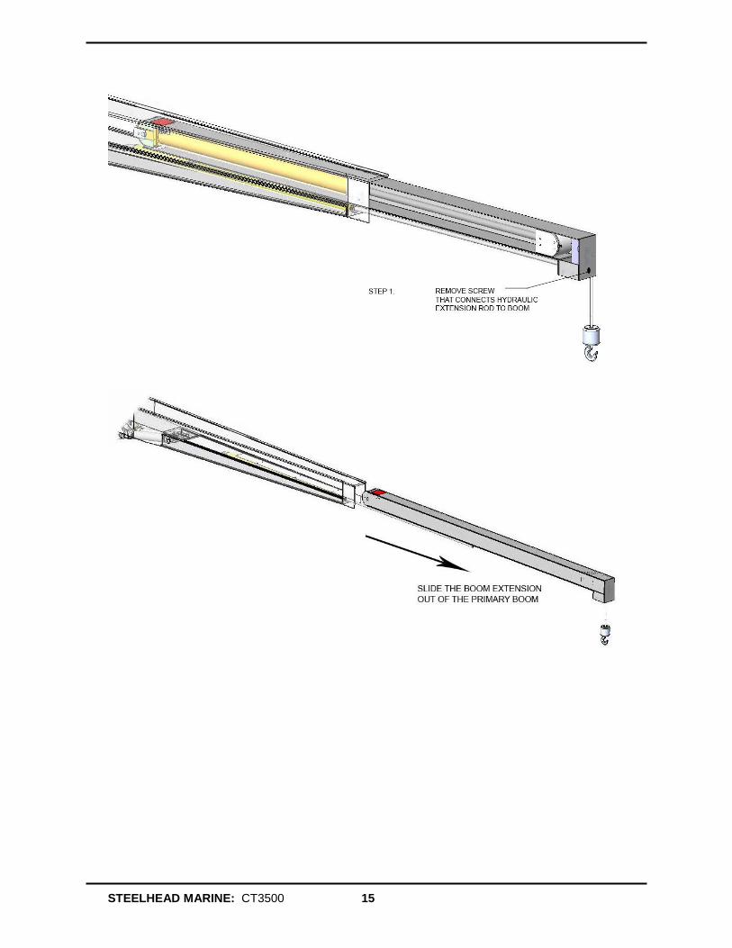
Linear Winch General Assembly Removal Linear Winch Spare Parts The Linear Winch comes supplied with dia. 1/2” AMSTEEL - BLUE rope. Only certified AMSTEEL - BLUE, diameter 1/2” can be used as a replacement.
STEELHEAD MARINE: CT3500 15

STEELHEAD MARINE: CT3500 16
LED Light Replacement CAPRERA LED Flood Light – Bracket Mount (part # 101040) www.yachtlights.com
Note: The LED light ramps in intensity over a period of 3 seconds on startup. With no interruption of this ramp the light will achieve and maintain full intensity. To enable a “dimmed mode” simply interrupt the ramp in intensity with a brief off/on toggle of power. This allows the intensity to be set anywhere from a soft glow to full power.
STEELHEAD MARINE: CT3500 17
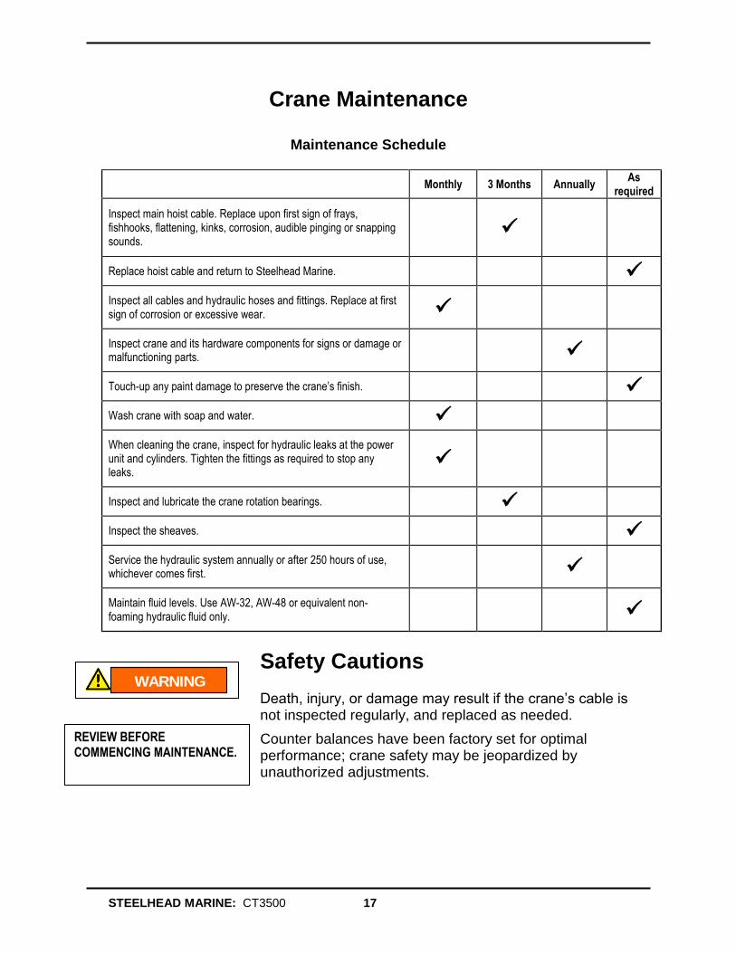
Crane Maintenance
Maintenance Schedule
Monthly 3 Months Annually As
required
Inspect main hoist cable. Replace upon first sign of frays, fishhooks, flattening, kinks, corrosion, audible pinging or snapping sounds.
Replace hoist cable and return to Steelhead Marine.
Inspect all cables and hydraulic hoses and fittings. Replace at first sign of corrosion or excessive wear.
Inspect crane and its hardware components for signs or damage or malfunctioning parts.
Touch-up any paint damage to preserve the crane’s finish.
Wash crane with soap and water.
When cleaning the crane, inspect for hydraulic leaks at the power unit and cylinders. Tighten the fittings as required to stop any leaks.
Inspect and lubricate the crane rotation bearings.
Inspect the sheaves.
Service the hydraulic system annually or after 250 hours of use, whichever comes first.
Maintain fluid levels. Use AW-32, AW-48 or equivalent non-foaming hydraulic fluid only.
Safety Cautions Death, injury, or damage may result if the crane’s cable is not inspected regularly, and replaced as needed.
Counter balances have been factory set for optimal performance; crane safety may be jeopardized by unauthorized adjustments.
WARNING
REVIEW BEFORE COMMENCING MAINTENANCE.
STEELHEAD MARINE: CT3500 18
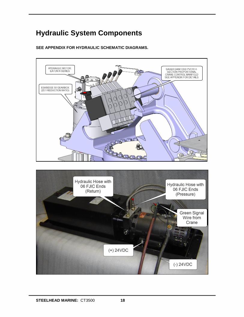
Hydraulic System Components SEE APPENDIX FOR HYDRAULIC SCHEMATIC DIAGRAMS.
STEELHEAD MARINE: CT3500 19
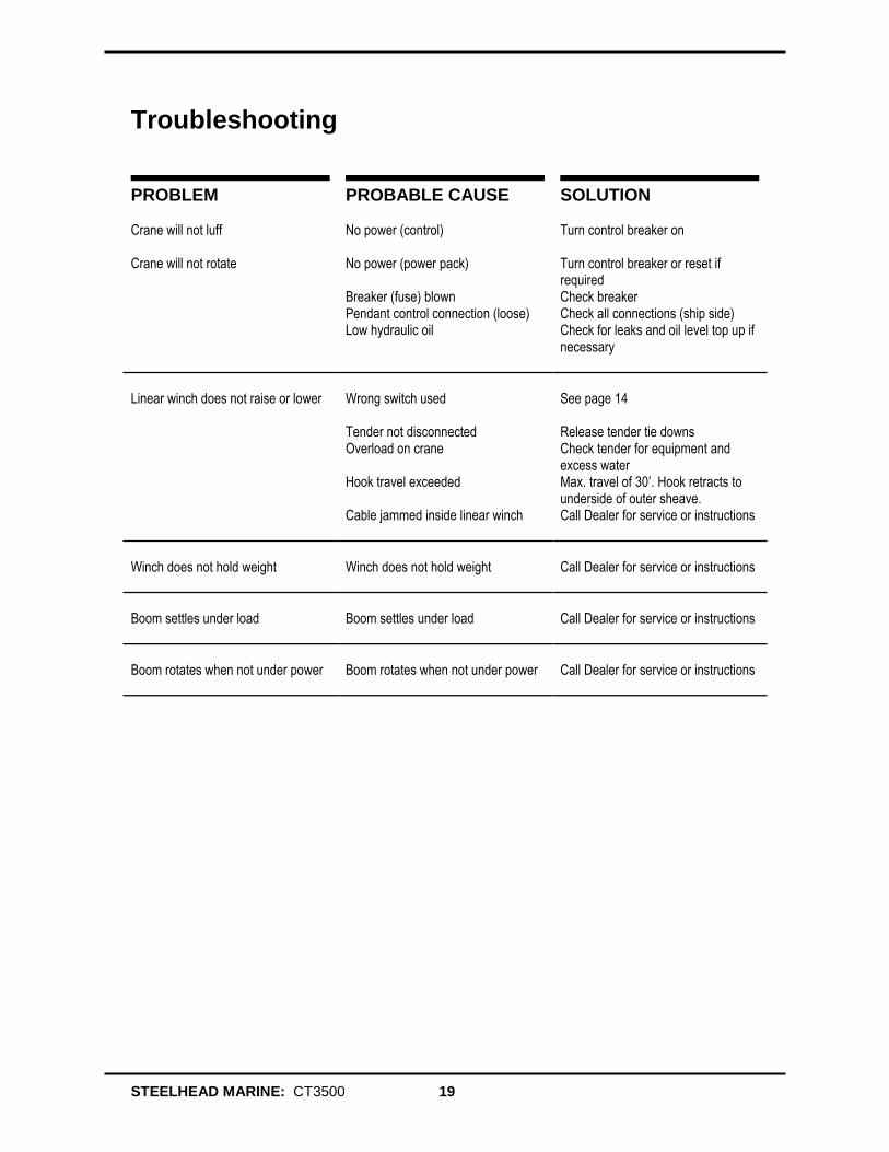
Troubleshooting
PROBLEM PROBABLE CAUSE SOLUTION Crane will not luff No power (control) Turn control breaker on
Crane will not rotate No power (power pack)
Breaker (fuse) blown Pendant control connection (loose) Low hydraulic oil
Turn control breaker or reset if required Check breaker Check all connections (ship side) Check for leaks and oil level top up if necessary
Linear winch does not raise or lower
Wrong switch used Tender not disconnected Overload on crane Hook travel exceeded Cable jammed inside linear winch
See page 14 Release tender tie downs Check tender for equipment and excess water Max. travel of 30’. Hook retracts to underside of outer sheave. Call Dealer for service or instructions
Winch does not hold weight
Winch does not hold weight
Call Dealer for service or instructions
Boom settles under load
Boom settles under load
Call Dealer for service or instructions
Boom rotates when not under power
Boom rotates when not under power
Call Dealer for service or instructions
STEELHEAD MARINE: CT3500 20
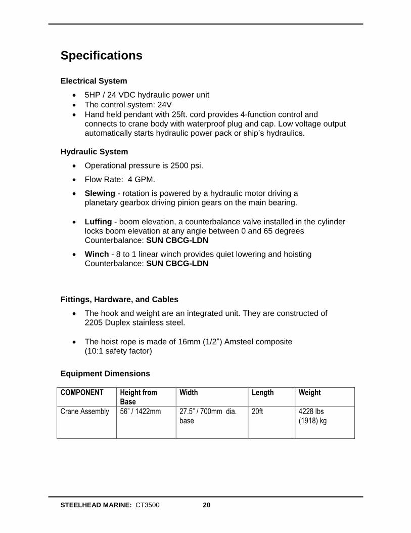
Specifications Electrical System
5HP / 24 VDC hydraulic power unit
The control system: 24V
Hand held pendant with 25ft. cord provides 4-function control and connects to crane body with waterproof plug and cap. Low voltage output automatically starts hydraulic power pack or ship’s hydraulics.
Hydraulic System
Operational pressure is 2500 psi.
Flow Rate: 4 GPM.
Slewing - rotation is powered by a hydraulic motor driving a planetary gearbox driving pinion gears on the main bearing.
Luffing - boom elevation, a counterbalance valve installed in the cylinder locks boom elevation at any angle between 0 and 65 degrees Counterbalance: SUN CBCG-LDN
Winch - 8 to 1 linear winch provides quiet lowering and hoisting Counterbalance: SUN CBCG-LDN
Fittings, Hardware, and Cables
The hook and weight are an integrated unit. They are constructed of 2205 Duplex stainless steel.
The hoist rope is made of 16mm (1/2”) Amsteel composite (10:1 safety factor)
Equipment Dimensions
COMPONENT Height from Base
Width Length Weight
Crane Assembly 56” / 1422mm 27.5” / 700mm dia. base
20ft 4228 lbs (1918) kg
STEELHEAD MARINE: CT3500 21
Warranty Steelhead Marine Ltd. (“Steelhead”) warrants to the original end-user (the “Buyer”) only that the yacht crane (the “Crane”) and its components are free from defective materials and workmanship for a period of two (2) years from the date of purchase by the Buyer when purchased from Steelhead or an authorized dealer of Steelhead. In the case of a new vessel, the warranty is valid from the commissioning date of the vessel.
This Limited Warranty covers the cost of shop labor and materials when the defective Crane or its components are delivered to Steelhead.
Examination of the Crane: The Buyer must examine the Crane upon delivery, and must report all defects to Steelhead within ten (10) days of said delivery, failing which it shall be conclusively agreed between Steelhead and the Buyer that the Crane has been delivered as specified in the contract. The Buyer shall report all visible shipping damage to the delivering shipping agent forthwith upon delivery. Failure to report shipping damage as provided above shall result in any and all shipping damage repair costs becoming the responsibility of the Buyer without recourse to Steelhead or the shipping agent.
Making a Warranty Claim: The Buyer shall establish its warranty claim by delivering to Steelhead at its Customer Service Center at #2 – 5367 271
st Street, Langley, British Columbia,
V4W 3Y7, within the period of this Limited Warranty, a statement in clear and concise terms setting forth the basis of the warranty claim together with proof of purchase, the make and model of the Crane, the date on which the Crane was installed, the name and return address of the party making the claim, and the name of the person or company installing the Crane. Upon receipt of a valid warranty claim, Steelhead reserves the right to either repair or replace the Crane or its components on board the vessel upon which it is installed, or require the Buyer to return the defective Crane or component(s) to Steelhead at its Customer Service Center at #2 – 5367 271
st
Street, Langley, British Columbia, V4W 3Y7, transportation prepaid.
This Limited Warranty shall include the cost of materials and labor for the repair or replacement of the Crane or its components at Steelhead’s Customer Service Center. This Limited Warranty also includes the Crane or its components to be repaired or replaced on board the vessel upon which it is installed, however, all expenses associated with transportation of product(s), transportation of field service technician(s), and all in-the-field collateral support (Crane service, welding service, painting service) are the Buyer’s responsibility.
Repaired or replaced products are warranted for the remaining portion of this original Limited Warranty period from the date the Crane was purchased by the Buyer.
Installation of Crane: If requested by the Buyer Steelhead will install the Crane or its components on board the vessel using its field service technicians, or at the sole discretion of Steelhead may nominate a third party installer of equivalent qualifications. Such third party installer/technician will be clearly identified in Steelhead’s commercial invoice with respect to the sale of the Crane or any of its components.
STEELHEAD MARINE: CT3500 22
Exclusions: This Limited Warranty shall not be effective and shall be void, if the Crane or its components are (i) not installed or used under normal conditions and as recommended by Steelhead; (ii) subjected to abuse, neglect, or carelessness; (iii) altered or repaired by anyone not authorized by Steelhead during the term of this Limited Warranty; (iv) subjected to lift dead weight in excess of rated capacity.; or (v) subjected to persons being the load or part of the load during operation of the Crane.
This Limited Warranty does not cover, and Steelhead is in no way responsible for any supporting or structural elements of the vessel upon which the Crane is installed, or any hoses, hydraulic fluids, filters, paint, or anodized finishes not supplied by Steelhead Marine. Except as expressly provided in this Limited Warranty, Steelhead is not responsible for the proper installation of the Crane or its supporting elements. It is the responsibility of the Buyer to ensure that the supporting and structural elements, and the Crane’s connection thereto, are properly engineered and can withstand the loads of the Crane while in operation. The Buyer shall periodically inspect all structural and supporting elements of the vessel and Crane, and all hoses and hydraulic assemblies for signs of wear, corrosion, and/or visible deterioration. The Buyer shall cease operation of the Crane at the first indication of deterioration.
This Limited Warranty shall not be valid except when delivered by an authorized representative of Steelhead or installing shipyard, and the Buyer shall not be entitled to rely on any other representations or warranties, whether oral or written, except as provided in this limited warranty.
THIS LIMITED WARRANTY IS IN LIEU OF ALL OTHER EXPRESS OR IMPLIED WARRANTIES. ANY WARRANTY IMPLIED BY STATUTE AND NOT EXCLUDED HEREIN, INCLUDING WARRANTIES OF MERCHANTABILITY OR FITNESS FOR A PARTICULAR PURPOSE, IS IN EFFECT ONLY DURING THE DURATION OF THE EXPRESS WARRANTY SET FORTH HEREIN.
This warranty gives the Buyer specific legal rights, and the Buyer may also have other rights which may vary from country to country or state to state. This warranty shall be construed pursuant to the laws of the Province of British Columbia.
STEELHEAD MARINE: CT3500 23
__________________________________________________
Steelhead Marine Ltd. Unit #2
5367 271st Street
Langley, British Columbia Canada, V4W 3Y7
Tel: 604-607-0091 Fax: 604-826-9992
Email: [email protected] www.steelheadmarine.net
©2013 Steelhead Marine Ltd
REV: A - 2013 Printed in Canada
![Manual # 99904560 20017 Crane Parts & Specificationsjmeengineering.com.au/images/pdf/20017-CRANE[1].pdf · Inspection Checklist ... Decals regarding crane safety and operation are](https://img.pdfslide.us/doc/110x75/5aab27367f8b9ac55c8b7573/manual-99904560-20017-crane-parts-specific-1pdfinspection-checklist-decals.jpg)