Embed Size (px)
Citation preview
104FE-OM0709-00
OPERATION MANUAL
MINI-CRAWLER CRANE
Serial No. E0001 and up
k WARNING
Unsafe use of this machine may cause serious injury or death. Operators must read this manual before operating this machine. This manual should be kept near the machine for reference and periodically reviewed by all personnel who will come into contact with it.
NOTICE
MAEDA has Operation Manual written in some other languages. If a foreign language manual is necessary, contact your local distributor for availability.

0-1
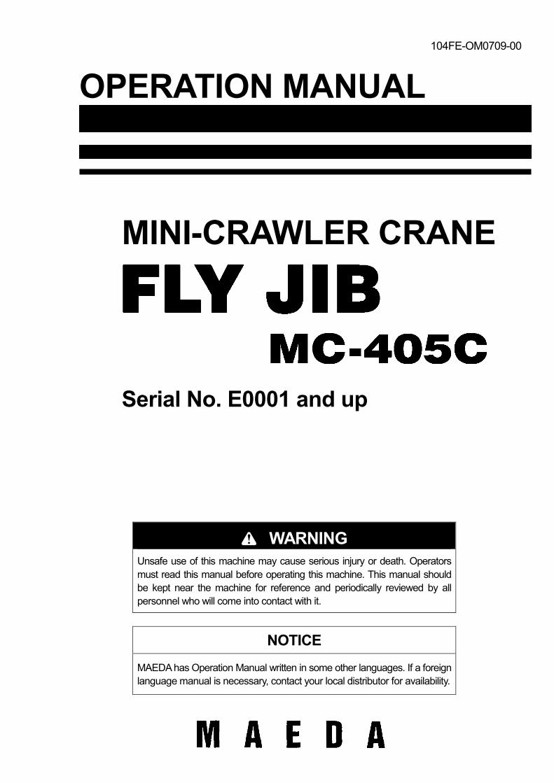
CONTENTS
Item Page PREFACE 1- 1 1. Preface 1- 2 2. Safety precautions 1- 3
SAFETY 2- 1 1. Position to post safety labels 2- 2
OPERATION 3- 1 1. Parts and Components names 3- 2 2. Working Range and Total Rated Load Charts 3- 3 3. Safety Precaution for Fly-Jib Operation 3- 4 4. Instruction for Fly-Jib operation 3- 6
4.1 Fly-jib Installation 3- 6 4.2 Change to single fall hook from main-boom hook block 3- 9 4.3 Diverting over hoist detector harness and protect weight 3-13 4.4 Instruction for Fly-Jib operation 3-14
5. Moment limiter control 3-16 5.1 Moment limiter display 3-16 5.2 Items of moment limiter restriction for operation 3-17
INSPECTION AND MAINTENANCE 4- 1 1. Precaution for maintenance work 4- 2 2. Legal inspection 4- 3 3. Consumables 4- 3 4. List of inspection and maintenance items 4- 3 5. Procedure 4- 4
5.1 Maintenance at initial ten hours of operation (First maintenance of new machine). 4- 4 5.2 Non-regular maintenance 4- 4 5.3 Daily opening inspection 4- 5 5.4 Maintenance per every 250 hours 4- 7

0-2
1-1
Preface
1. Preface 1- 2 2. Safety precautions 1- 3
1-2
1. Preface Thank you for your purchase of our “Fly-Jib” kit for Maeda Mini Crawler Crane MC-405C. This guide book covers safety and effective operation of the “Fly-Jib” kit. This guidebook specifies procedure for operation and maintenance of this kit, as well as safety precautions which must be observed during all phases of such operation and maintenance. Most of hazards and accidents are the result of failure to comply with these precautions or with specific WARNINGS for operation, inspection and/or maintenance practices. Before installation, operation, maintenance and inspection, be sure to read this instruction carefully, and use it in the correct way. Failure to comply with these precautions may result serious hazard.
k WARNING Careless operation of this device could result in serious injury or death to personnel. Prior to practice of operation and maintenance of this kit, operators and maintenance personnel should read this instruction carefully. Please keep this manual in a prearranged place for easy access of members concerned, who should familiarize it. ・Never try to bring this kit into operation unless contents of this document is comprehended. ・Always keep this document accessible and refer whenever required. ・In the event of loss or impairment, please immediately order us or our sales partners for replacement. ・Whenever you sell off this kit, be sure to attach this document with it. ・Descriptions, values and illustrations herein have been produced upon the latest information of the date
when it was prepared. Contents of this manual, including maintenance standard, tightening torque range, pressure range, inspection practices, adjustment rate or illustrations, are subject to change without prior notice due to our infinite attempt for improvement. Since these changes may affect performance of proper maintenance, please contact us or our sales partners for latest information, before starting maintenance work.
“2. Safety precaution” in page 1-3, as well as the next section, “Safety” in page 2-1 cover essential safety instructions.
1-3
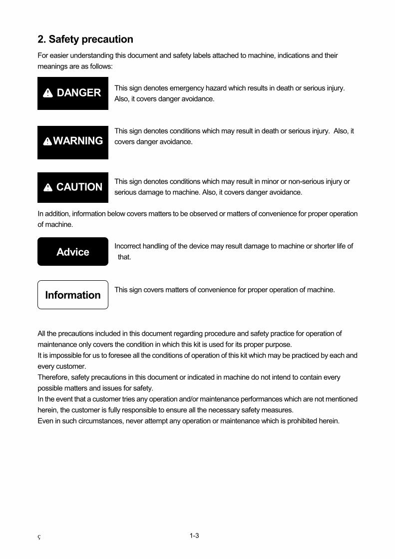
2. Safety precaution For easier understanding this document and safety labels attached to machine, indications and their meanings are as follows:
This sign denotes emergency hazard which results in death or serious injury. Also, it covers danger avoidance. This sign denotes conditions which may result in death or serious injury. Also, it covers danger avoidance. This sign denotes conditions which may result in minor or non-serious injury or serious damage to machine. Also, it covers danger avoidance.
In addition, information below covers matters to be observed or matters of convenience for proper operation of machine.
Incorrect handling of the device may result damage to machine or shorter life of that.
This sign covers matters of convenience for proper operation of machine.
All the precautions included in this document regarding procedure and safety practice for operation of maintenance only covers the condition in which this kit is used for its proper purpose. It is impossible for us to foresee all the conditions of operation of this kit which may be practiced by each and every customer. Therefore, safety precautions in this document or indicated in machine do not intend to contain every possible matters and issues for safety. In the event that a customer tries any operation and/or maintenance performances which are not mentioned herein, the customer is fully responsible to ensure all the necessary safety measures. Even in such circumstances, never attempt any operation or maintenance which is prohibited herein.
kkkk DANGER
kkkk WARNING
kkkk CAUTION
Advice
Information

1-4
2-1
Safety
1. Position to post safety labels 2- 2
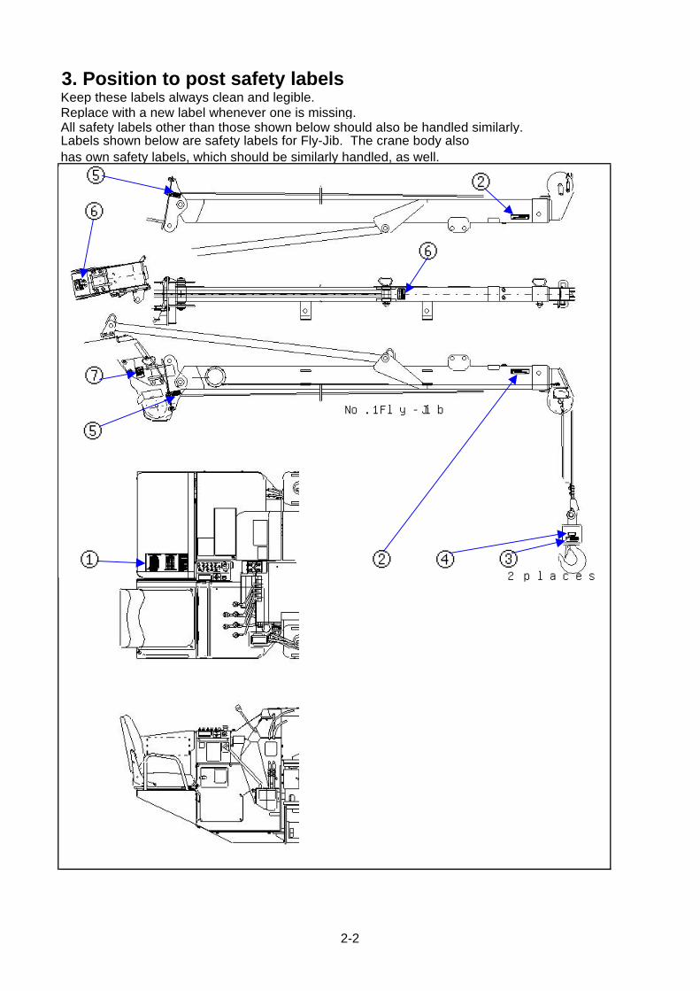
3. Position to post safety labelsKeep these labels always clean and legible. Replace with a new label whenever one is missing.All safety labels other than those shown below should also be handled similarly. Labels shown below are safety labels for Fly-Jib. The crane body alsohas own safety labels, which should be similarly handled, as well.
No.1Fly-Jib
③④②
②
2 labels①
No.1Fly-Jib
③④②
②
2 places①
⑤
⑥
⑦
⑤
⑥
2-2
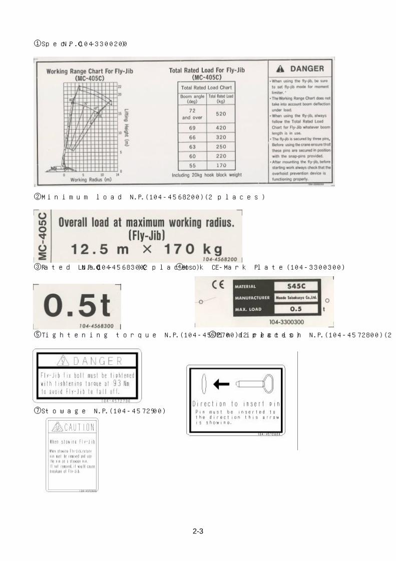
①Spec N.P.(104-3300200)
②Minimum load N.P.(104-4568200)(2 places)
③Rated Load N.P.(104-4568300)(2 places) ④Hook CE-Mark Plate(104-3300300)
⑤Tightening torque N.P.(104-4572700)(2 places) ⑥Pin direction N.P.(104-4572800)(2 places)
⑦Stowage N.P.(104-4572900)
2-3

2-4
3-1
Operation
1. Parts and Components names 3- 2 2. Working Range and Total Rated Load Charts 3- 3 3. Safety Precaution for Fly-Jib Operation 3- 4 4. Instruction for Fly-Jib operation 3- 6
4.1 Fly-jib Installation 3- 6 4.2 Change to single fall hook from main-boom hook block 3- 9 4.3 Diverting over hoist detector harness and protect weight 3-13 4.4 Instruction for Fly-Jib operation 3-14
5. Moment limiter control 3-16 5.1 Moment limiter display 3-16 5.2 Items of moment limiter restriction for operation 3-17
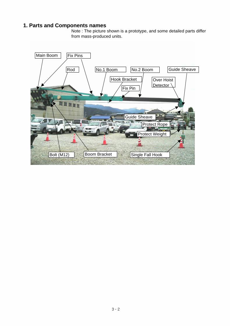
1. Parts and Components names
from mass-produced units.Note : The picture shown is a prototype, and some detailed parts differ
No.2 Boom Guide Sheave
Hook Bracket
No.1 BoomRod
Fix Pins
Fix Pin
Over HoistDetector
Protect Weight
Protect Rope
Single Fall Hook
Guide Sheave
Main Boom
Boom BracketBolt (M12)
3-2
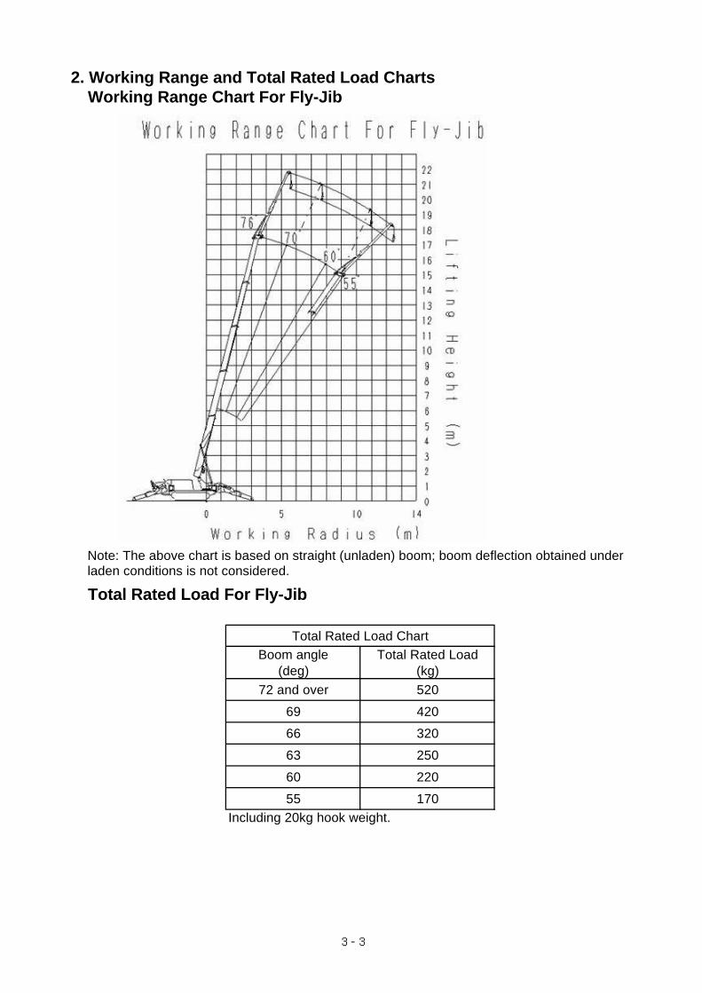
2. Working Range and Total Rated Load ChartsWorking Range Chart For Fly-Jib
laden conditions is not considered.
Total Rated Load For Fly-Jib
Total Rated Load ChartBoom angle Total Rated Load
(deg) (kg)72 and over 520
69 420
66 320
63 250
60 220
55 170Including 20kg hook weight.
Note: The above chart is based on straight (unladen) boom; boom deflection obtained under
3-3
3. Safety Precaution for Fly-Jib Operation
・fly-jib kit under operation should be fixed by four bolts and three fix pins. Prior to start
operation, always assure that all of three pins are set in positions correctly, as well as
that four sets of bolts and nuts are driven tightly.
In addition, ensure that snap retainers are correctly inserted to three fix pins to prevent them missing.
・When stowed, fly-jib is fitted to main-boom with two stowage pins. Prior to let the crane body
travel, make sure that two pins are properly secured.
Also, ensure that snap retainers are correctly inserted to these two pins to prevent them missing.
・Always check correct function of over hoist detector before starting fly-jib operation.
・Always fully extend two stages of Fly-Jib in use, because moment limiter's fly-jib mode
calculates and indicates working radius and lifting height on basis of full length.
・Always make outriggers contact to the ground for fly-jib operation.
(Outriggers position may be minimum extended.)
・Never pick and carry by fly-jib. It is a hazardous operation.
Please refer to MC-405C Operation Manual (separate volume) for general precautions
for safety operations.
WARNING
3-4

3-5
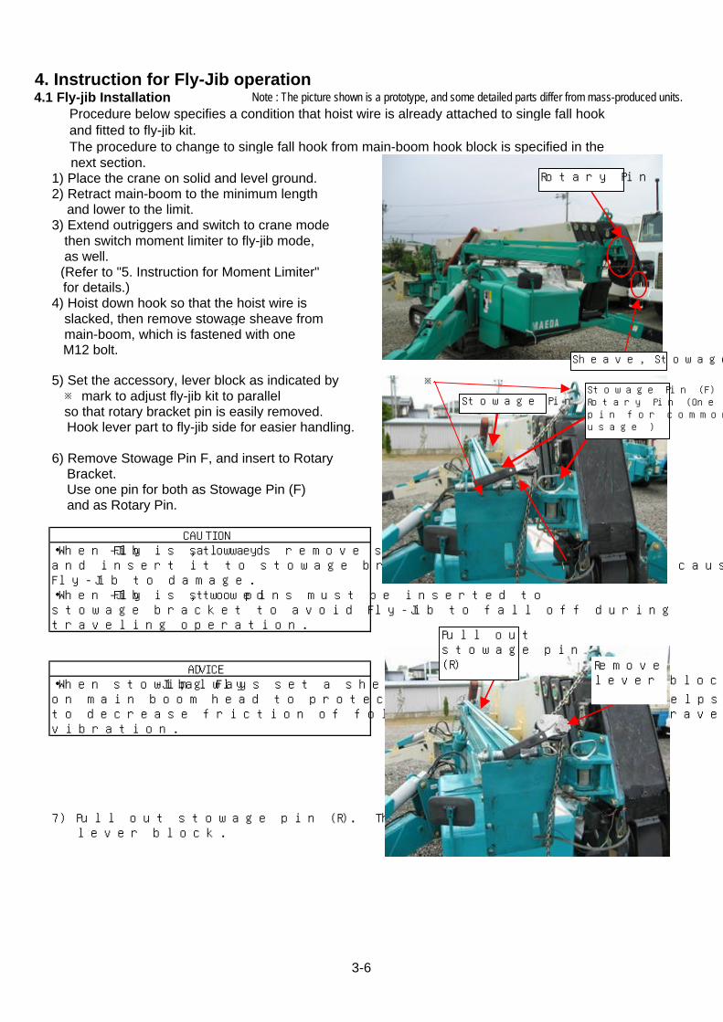
4. Instruction for Fly-Jib operation 4.1 Fly-jib Installation Note : The picture shown is a prototype, and some detailed parts differ from mass-produced units.
Procedure below specifies a condition that hoist wire is already attached to single fall hook and fitted to fly-jib kit. The procedure to change to single fall hook from main-boom hook block is specified in the next section. 1) Place the crane on solid and level ground.2) Retract main-boom to the minimum length and lower to the limit.3) Extend outriggers and switch to crane mode then switch moment limiter to fly-jib mode, as well. (Refer to "5. Instruction for Moment Limiter" for details.)4) Hoist down hook so that the hoist wire is slacked, then remove stowage sheave from main-boom, which is fastened with one M12 bolt.
5) Set the accessory, lever block as indicated by ※ mark to adjust fly-jib kit to parallel so that rotary bracket pin is easily removed. Hook lever part to fly-jib side for easier handling.
6) Remove Stowage Pin F, and insert to Rotary Bracket. Use one pin for both as Stowage Pin (F) and as Rotary Pin.
CAUTION
ADVICE
7) Pull out stowage pin (R). Then remove lever block.
・When Fly-Jib is stowed, always remove stowage pinand insert it to stowage bracket. If not, it could causeFly-Jib to damage.・When Fly-Jib is stowed, two pins must be inserted tostowage bracket to avoid Fly-Jib to fall off duringtraveling operation.
・When stowing Fly-Jib, always set a sheave for stowageon main boom head to protect winch wire rope. It helpsto decrease friction of folded wire caused from travelingvibration.
※
Sheave, Stowage
Rotary Pin
Pull outstowage pin(R) Remove
lever block
Stowage Pin (R)Stowage Pin (F)Rotary Pin (Onepin for commonusage )
3-6
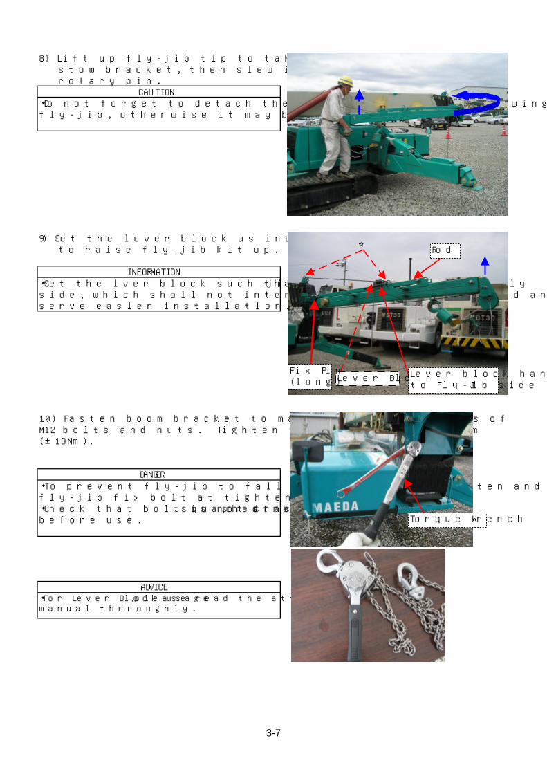
8) Lift up fly-jib tip to take it out from stow bracket, then slew it around the rotary pin.
CAUTION
9) Set the lever block as indicated by ☆mark to raise fly-jib kit up.
・Set the lver block such that its handle comes to fly-jibside, which shall not interfere the movement of rod andserve easier installation.
・Do not forget to detach the lever block before slewingfly-jib, otherwise it may be damaged.
INFORMATION
10) Fasten boom bracket to main-boom using 4 sets ofM12 bolts and nuts. Tighten them to torque of 93Nm(±13Nm).
DANGER・To prevent fly-jib to fall off, be sure to tighten and fixfly-jib fix bolt at tightening torque of 93Nm.・Check that bolt is not cracked, squashed, or stretchedbefore use.
ADVICE ・For Lever Block usage, please read the attached operationmanual thoroughly.
☆
Lever Block Lever block handleto Fly-Jib side
Rod
Fix Pin(long)
Torque Wrench
3-7
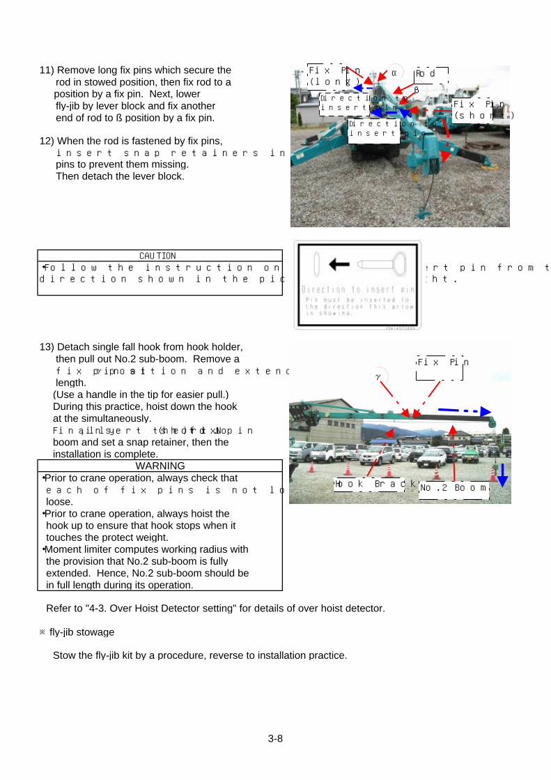
11) Remove long fix pins which secure the rod in stowed position, then fix rod to a position by a fix pin. Next, lower fly-jib by lever block and fix another end of rod to ß position by a fix pin.
12) When the rod is fastened by fix pins, insert snap retainers into tips of fix pins to prevent them missing. Then detach the lever block.
13) Detach single fall hook from hook holder, then pull out No.2 sub-boom. Remove a fix pin at γ position and extend it to full length. (Use a handle in the tip for easier pull.) During this practice, hoist down the hook at the simultaneously. Finally, insert the fix pin (short) to No.1 boom and set a snap retainer, then the installation is complete.
WARNING・Prior to crane operation, always check that each of fix pins is not lost nor bolts are not loose.・Prior to crane operation, always hoist the hook up to ensure that hook stops when it touches the protect weight.・Moment limiter computes working radius with the provision that No.2 sub-boom is fully extended. Hence, No.2 sub-boom should be in full length during its operation.
Refer to "4-3. Over Hoist Detector setting" for details of over hoist detector.
※fly-jib stowage Stow the fly-jib kit by a procedure, reverse to installation practice.
・Follow the instruction on decal, and insert pin from thedirection shown in the picture on the right.
CAUTION
Fix Pin(long)
Fix Pin(short)
Rodα
β
Fix Pin
Hook Bracket No.2 Boom
γ
Direction toinsert pin
Direction toinsert pin
3-8
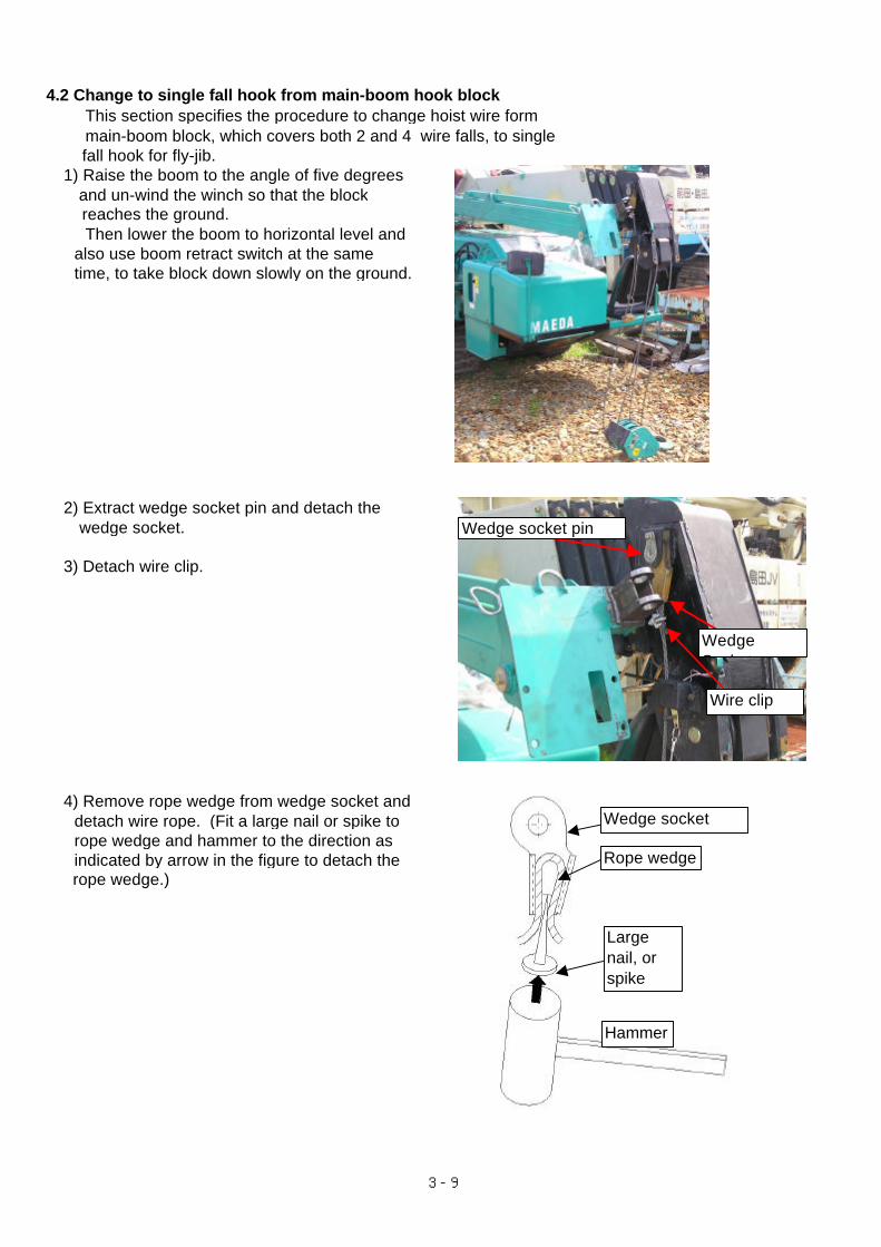
4.2 Change to single fall hook from main-boom hook block This section specifies the procedure to change hoist wire form main-boom block, which covers both 2 and 4 wire falls, to single fall hook for fly-jib. 1) Raise the boom to the angle of five degrees and un-wind the winch so that the block reaches the ground. Then lower the boom to horizontal level and also use boom retract switch at the same time, to take block down slowly on the ground.
2) Extract wedge socket pin and detach the wedge socket.
3) Detach wire clip.
4) Remove rope wedge from wedge socket and detach wire rope. (Fit a large nail or spike to rope wedge and hammer to the direction as indicated by arrow in the figure to detach the rope wedge.)
Wedge socket pin
WedgeSocket
Wire clip
Wedge socket
Rope wedge
Largenail, orspike
Hammer
3-9
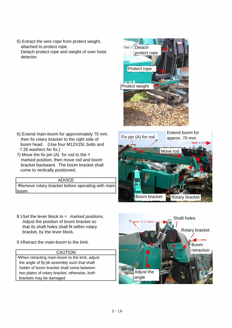
5) Extract the wire rope from protect weight, attached to protect rope. Detach protect rope and weight of over hoist detector.
6) Extend main-boom for approximately 70 mm. then fix rotary bracket to the right side of boom head. (Use four M12X25L bolts and f 26 washers for fix.)7) Move the fix pin (A) for rod to the ☆ marked position, then move rod and boom bracket backward. The boom bracket shall come to vertically positioned.
8) Set the lever block to ※ marked positions. Adjust the position of boom bracket so that its shaft holes shall fit within rotary bracket, by the lever block.
9) Retract the main-boom to the limit.
CAUTION・When retracting main-boom to the limit, adjust the angle of fly-jib assembly such that shaft holder of boom bracket shall come between two plates of rotary bracket, otherwise, both brackets may be damaged.
ADVICE・Remove rotary bracket before operating with mainboom.
Fix pin (A) for rod☆
Extend boom forapprox. 70 mm.
Move rod
※Shaft holes
Rotary bracket
Boomretraction
Protect rope
Detachprotect rope
Protect weight
Rotary bracket
Adjust theangle
Boom bracket
3-10
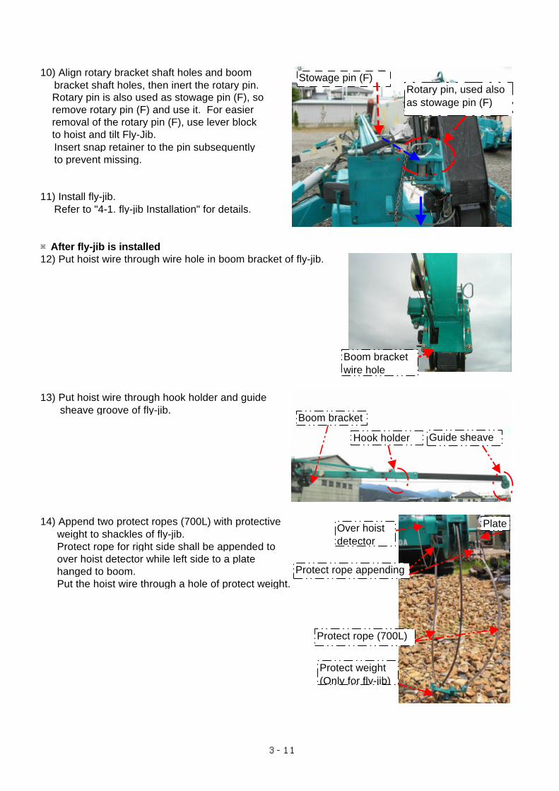
10) Align rotary bracket shaft holes and boom bracket shaft holes, then inert the rotary pin. Rotary pin is also used as stowage pin (F), so remove rotary pin (F) and use it. For easier removal of the rotary pin (F), use lever block to hoist and tilt Fly-Jib. Insert snap retainer to the pin subsequently to prevent missing.
11) Install fly-jib. Refer to "4-1. fly-jib Installation" for details.
※After fly-jib is installed12) Put hoist wire through wire hole in boom bracket of fly-jib.
13) Put hoist wire through hook holder and guide sheave groove of fly-jib.
14) Append two protect ropes (700L) with protective weight to shackles of fly-jib. Protect rope for right side shall be appended to over hoist detector while left side to a plate hanged to boom. Put the hoist wire through a hole of protect weight.
Boom bracket
Guide sheaveHook holder
Boom bracketwire hole
Protect rope (700L)
Protect rope appending
Protect weight(Only for fly-jib)
PlateOver hoistdetector
Rotary pin, used alsoas stowage pin (F)
Stowage pin (F)
3-11
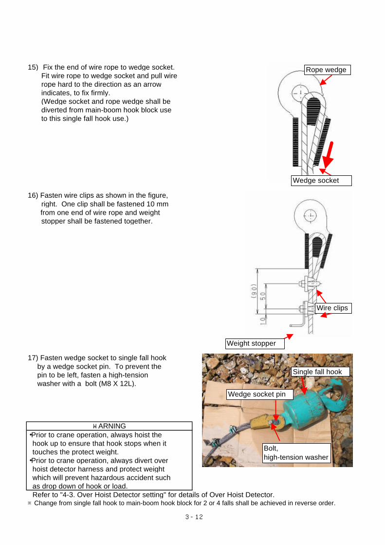
15) Fix the end of wire rope to wedge socket. Fit wire rope to wedge socket and pull wire rope hard to the direction as an arrow indicates, to fix firmly. (Wedge socket and rope wedge shall be diverted from main-boom hook block use to this single fall hook use.)
16) Fasten wire clips as shown in the figure, right. One clip shall be fastened 10 mm from one end of wire rope and weight stopper shall be fastened together.
17) Fasten wedge socket to single fall hook by a wedge socket pin. To prevent the pin to be left, fasten a high-tension washer with a bolt (M8 X 12L).
・Prior to crane operation, always hoist the hook up to ensure that hook stops when it touches the protect weight.・Prior to crane operation, always divert over hoist detector harness and protect weight which will prevent hazardous accident such as drop down of hook or load. Refer to "4-3. Over Hoist Detector setting" for details of Over Hoist Detector.※Change from single fall hook to main-boom hook block for 2 or 4 falls shall be achieved in reverse order.
WARNING
Rope wedge
Wedge socket
Wire clips
Weight stopper
Single fall hook
Wedge socket pin
Bolt,high-tension washer
3-12
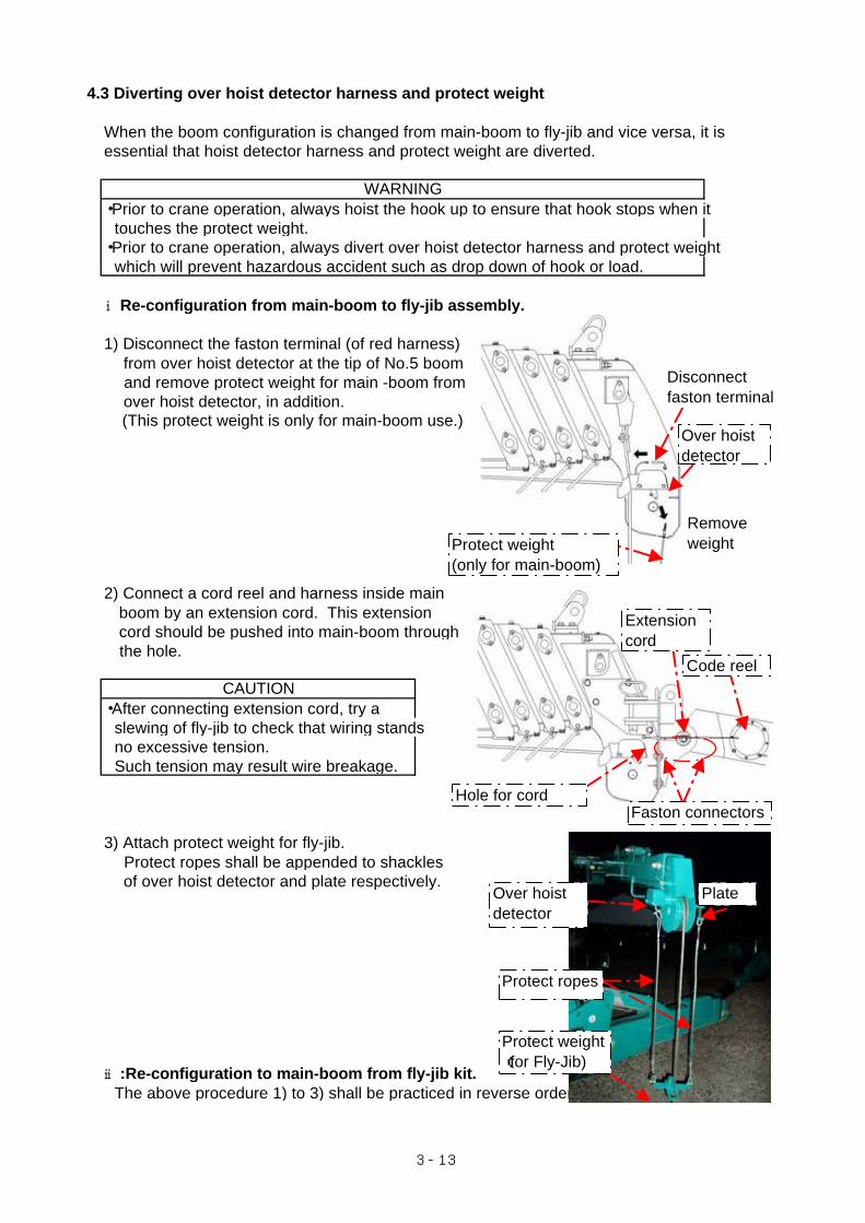
4.3 Diverting over hoist detector harness and protect weight
When the boom configuration is changed from main-boom to fly-jib and vice versa, it is essential that hoist detector harness and protect weight are diverted.
・Prior to crane operation, always hoist the hook up to ensure that hook stops when it touches the protect weight.・Prior to crane operation, always divert over hoist detector harness and protect weight which will prevent hazardous accident such as drop down of hook or load.
ⅰRe-configuration from main-boom to fly-jib assembly.
1) Disconnect the faston terminal (of red harness) from over hoist detector at the tip of No.5 boom and remove protect weight for main -boom from over hoist detector, in addition. (This protect weight is only for main-boom use.)
2) Connect a cord reel and harness inside main boom by an extension cord. This extension cord should be pushed into main-boom through the hole.
・After connecting extension cord, try a slewing of fly-jib to check that wiring stands no excessive tension. Such tension may result wire breakage.
3) Attach protect weight for fly-jib. Protect ropes shall be appended to shackles of over hoist detector and plate respectively.
ⅱ:Re-configuration to main-boom from fly-jib kit. The above procedure 1) to 3) shall be practiced in reverse order.
WARNING
CAUTION
Disconnectfaston terminal
Over hoistdetector
Protect weight(only for main-boom)
Code reel
Extensioncord
Removeweight
Faston connectors
Protect weight(for Fly-Jib)
Protect ropes
PlateOver hoistdetector
Hole for cord
3-13
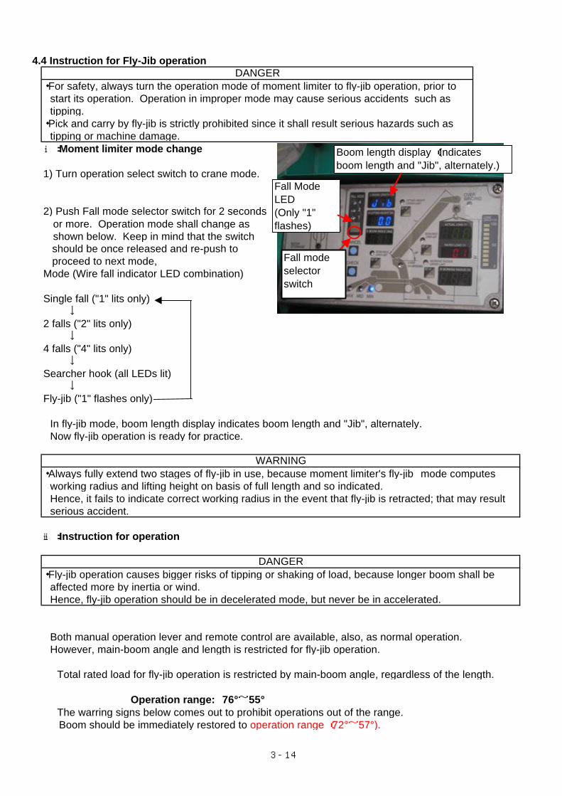
4.4 Instruction for Fly-Jib operation
・For safety, always turn the operation mode of moment limiter to fly-jib operation, prior to start its operation. Operation in improper mode may cause serious accidents such as tipping.・Pick and carry by fly-jib is strictly prohibited since it shall result serious hazards such as tipping or machine damage.ⅰ:Moment limiter mode change
1) Turn operation select switch to crane mode.
2) Push Fall mode selector switch for 2 seconds or more. Operation mode shall change as shown below. Keep in mind that the switch should be once released and re-push to proceed to next mode,Mode (Wire fall indicator LED combination)
Single fall ("1" lits only)↓
2 falls ("2" lits only)↓
4 falls ("4" lits only)↓
Searcher hook (all LEDs lit)↓
Fly-jib ("1" flashes only)
In fly-jib mode, boom length display indicates boom length and "Jib", alternately. Now fly-jib operation is ready for practice.
・Always fully extend two stages of fly-jib in use, because moment limiter's fly-jib mode computes working radius and lifting height on basis of full length and so indicated. Hence, it fails to indicate correct working radius in the event that fly-jib is retracted; that may result serious accident.
ⅱ:Instruction for operation
・Fly-jib operation causes bigger risks of tipping or shaking of load, because longer boom shall be affected more by inertia or wind. Hence, fly-jib operation should be in decelerated mode, but never be in accelerated.
Both manual operation lever and remote control are available, also, as normal operation. However, main-boom angle and length is restricted for fly-jib operation.
Total rated load for fly-jib operation is restricted by main-boom angle, regardless of the length.
Operation range: 76°~55° The warring signs below comes out to prohibit operations out of the range. Boom should be immediately restored to operation range (72°~57°).
DANGER
WARNING
DANGER
Fall modeselectorswitch
Fall ModeLED(Only "1"flashes)
Boom length display (Indicatesboom length and "Jib", alternately.)
3-14
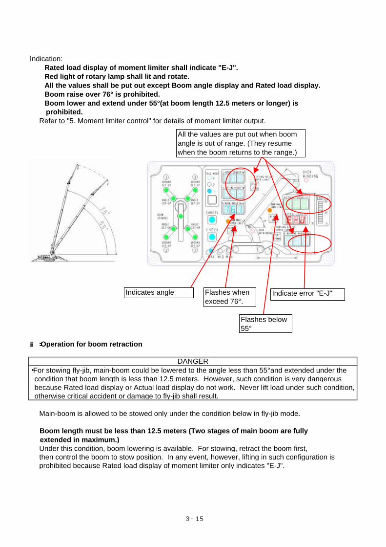
Indication: Rated load display of moment limiter shall indicate "E-J". Red light of rotary lamp shall lit and rotate. All the values shall be put out except Boom angle display and Rated load display. Boom raise over 76° is prohibited. Boom lower and extend under 55°(at boom length 12.5 meters or longer) is prohibited. Refer to "5. Moment limiter control" for details of moment limiter output.
ⅲ:Operation for boom retraction
・For stowing fly-jib, main-boom could be lowered to the angle less than 55°and extended under the condition that boom length is less than 12.5 meters. However, such condition is very dangerous because Rated load display or Actual load display do not work. Never lift load under such condition, otherwise critical accident or damage to fly-jib shall result.
Main-boom is allowed to be stowed only under the condition below in fly-jib mode.
Boom length must be less than 12.5 meters (Two stages of main boom are fully extended in maximum.) Under this condition, boom lowering is available. For stowing, retract the boom first, then control the boom to stow position. In any event, however, lifting in such configuration is prohibited because Rated load display of moment limiter only indicates "E-J".
DANGER
Indicate error "E-J"Indicates angle Flashes whenexceed 76°.
Flashes below55°
All the values are put out when boomangle is out of range. (They resumewhen the boom returns to the range.)
3-15
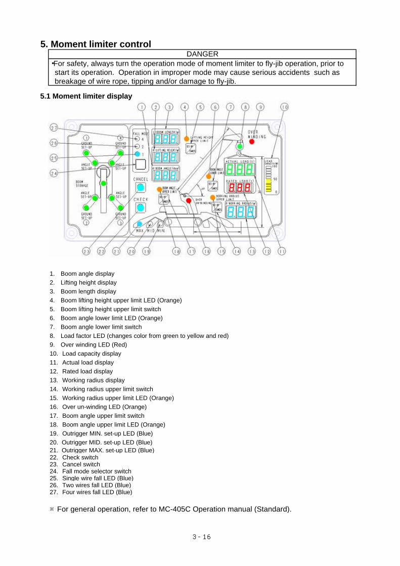
5. Moment limiter control
・For safety, always turn the operation mode of moment limiter to fly-jib operation, prior to start its operation. Operation in improper mode may cause serious accidents such as breakage of wire rope, tipping and/or damage to fly-jib.
5.1 Moment limiter display
1. Boom angle display2. Lifting height display3. Boom length display4. Boom lifting height upper limit LED (Orange)5. Boom lifting height upper limit switch6. Boom angle lower limit LED (Orange)7. Boom angle lower limit switch8. Load factor LED (changes color from green to yellow and red)9. Over winding LED (Red)10. Load capacity display11. Actual load display12. Rated load display13. Working radius display14. Working radius upper limit switch15. Working radius upper limit LED (Orange)16. Over un-winding LED (Orange)17. Boom angle upper limit switch18. Boom angle upper limit LED (Orange)19. Outrigger MIN. set-up LED (Blue)20. Outrigger MID. set-up LED (Blue)21. Outrigger MAX. set-up LED (Blue)22. Check switch23. Cancel switch24. Fall mode selector switch25. Single wire fall LED (Blue)26. Two wires fall LED (Blue)27. Four wires fall LED (Blue)
※For general operation, refer to MC-405C Operation manual (Standard).
DANGER
3-16
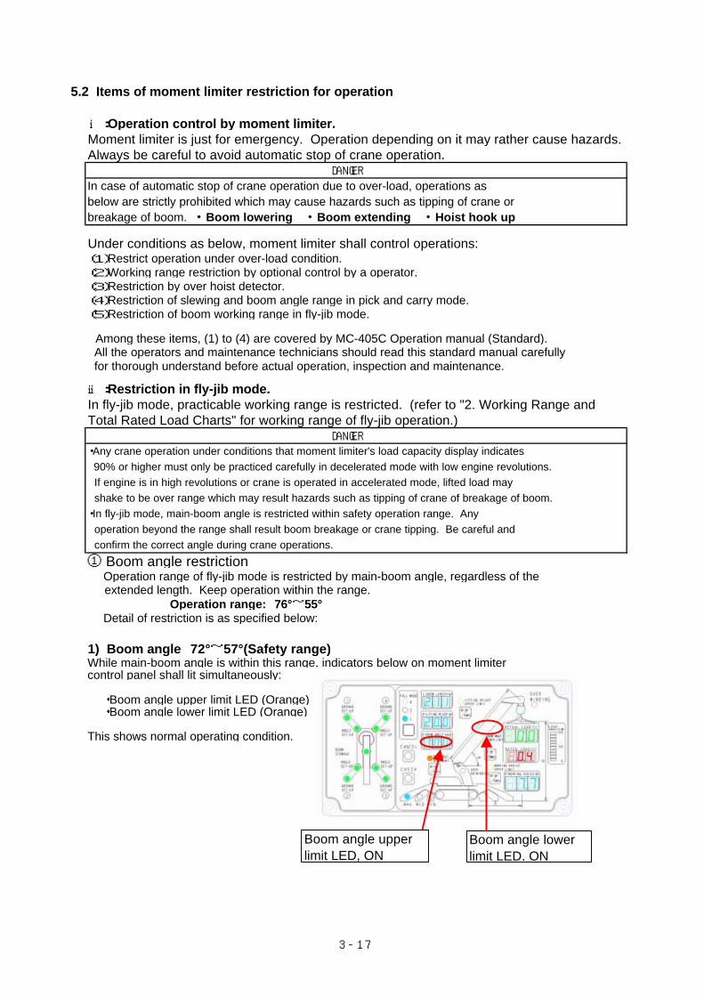
5.2 Items of moment limiter restriction for operation
ⅰ:Operation control by moment limiter.Moment limiter is just for emergency. Operation depending on it may rather cause hazards. Always be careful to avoid automatic stop of crane operation.
In case of automatic stop of crane operation due to over-load, operations as below are strictly prohibited which may cause hazards such as tipping of crane or breakage of boom. ・Boom lowering ・Boom extending ・Hoist hook up
Under conditions as below, moment limiter shall control operations:(1)Restrict operation under over-load condition.(2)Working range restriction by optional control by a operator.(3)Restriction by over hoist detector.(4)Restriction of slewing and boom angle range in pick and carry mode.(5)Restriction of boom working range in fly-jib mode.
Among these items, (1) to (4) are covered by MC-405C Operation manual (Standard). All the operators and maintenance technicians should read this standard manual carefully for thorough understand before actual operation, inspection and maintenance. ⅱ:Restriction in fly-jib mode.In fly-jib mode, practicable working range is restricted. (refer to "2. Working Range and Total Rated Load Charts" for working range of fly-jib operation.)
・Any crane operation under conditions that moment limiter's load capacity display indicates 90% or higher must only be practiced carefully in decelerated mode with low engine revolutions. If engine is in high revolutions or crane is operated in accelerated mode, lifted load may shake to be over range which may result hazards such as tipping of crane of breakage of boom.・In fly-jib mode, main-boom angle is restricted within safety operation range. Any operation beyond the range shall result boom breakage or crane tipping. Be careful and confirm the correct angle during crane operations.
① Boom angle restriction Operation range of fly-jib mode is restricted by main-boom angle, regardless of the extended length. Keep operation within the range.
Operation range: 76°~55° Detail of restriction is as specified below:
1) Boom angle 72°~57°(Safety range)While main-boom angle is within this range, indicators below on moment limiter control panel shall lit simultaneously:
・Boom angle upper limit LED (Orange) ・Boom angle lower limit LED (Orange)
This shows normal operating condition.
DANGER
DANGER
Boom angle upperlimit LED, ON
Boom angle lowerlimit LED, ON
3-17
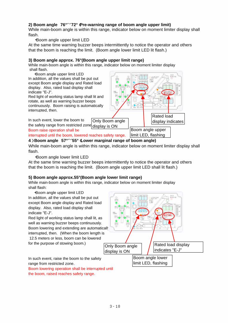
2) Boom angle 76°~72°(Pre-warning range of boom angle upper limit)
・Boom angle upper limit LEDAt the same time warning buzzer beeps intermittently to notice the operator and others that the boom is reaching the limit. (Boom angle lower limit LED lit flash.)
3) Boom angle approx. 76°(Boom angle upper limit range)While main-boom angle is within this range, indicator below on moment limiter display shall flash. ・Boom angle upper limit LEDIn addition, all the values shall be put out except Boom angle display and Rated load display. Also, rated load display shallindicate "E-J".Red light of working status lamp shall lit and rotate, as well as warning buzzer beeps continuously. Boom raising is automatically interrupted, then.
In such event, lower the boom to the safety range from restricted zone. Boom raise operation shall be interrupted until the boom, lowered reaches safety range. 4) Boom angle 57°~55°(Lower marginal range of boom angle)
・Boom angle lower limit LEDAt the same time warning buzzer beeps intermittently to notice the operator and others that the boom is reaching the limit. (Boom angle upper limit LED shall lit flash.)
5) Boom angle approx.55°(Boom angle lower limit range)While main-boom angle is within this range, indicator below on moment limiter displayshall flash: ・Boom angle upper limit LEDIn addition, all the values shall be put out except Boom angle display and Rated load display. Also, rated load display shallindicate "E-J".Red light of working status lamp shall lit, as well as warning buzzer beeps continuously. Boom lowering and extending are automatically interrupted, then. (When the boom length is 12.5 meters or less, boom can be lowered for the purpose of stowing boom.)
In such event, raise the boom to the safety range from restricted zone. Boom lowering operation shall be interrupted until the boom, raised reaches safety range.
While main-boom angle is within this range, indicator below on moment limiter display shallflash.
While main-boom angle is within this range, indicator below on moment limiter display shallflash.
Rated loaddisplay indicates
Boom angle upperlimit LED, flashing
Only Boom angledisplay is ON
Only Boom angledisplay is ON
Boom angle lowerlimit LED, flashing
Rated load displayindicates "E-J"
3-18
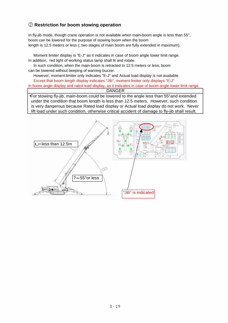
② Restriction for boom stowing operation
In fly-jib mode, though crane operation is not available when main-boom angle is less than 55°, boom can be lowered for the purpose of stowing boom when the boomlength is 12.5 meters or less (; two stages of main boom are fully extended in maximum).
Moment limiter display is "E-J" as it indicates in case of boom angle lower limit range.In addition, red light of working status lamp shall lit and rotate. In such condition, when the main-boom is retracted to 12.5 meters or less, boomcan be lowered without beeping of warning buzzer. However, moment limiter only indicates "E-J" and Actual load display is not available. Except that boom length display indicates "JIb", moment limiter only displays "E-J"in boom angle display and rated load display, as it indicates in case of boom angle lower limit range.
・For stowing fly-jib, main-boom could be lowered to the angle less than 55°and extended under the condition that boom length is less than 12.5 meters. However, such condition is very dangerous because Rated load display or Actual load display do not work. Never lift load under such condition, otherwise critical accident of damage to fly-jib shall result.
DANGER
L=less than 12.5m
?=55°or less
"Jib" is indicated
3-19

3-20

4-1
Inspection and Maintenance
1. Precaution for maintenance work 4- 2 2. Legal inspection 4- 3 3. Consumables 4- 3 4. List of inspection and maintenance items 4- 3 5. Procedure 4- 4
5.1 Maintenance at initial ten hours of operation (First maintenance of new machine) 4- 4
5.2 Non-regular maintenance 4- 4 5.3 Daily opening inspection 4- 5 5.4 Maintenance per every 250 hours 4- 7
1. Precaution for maintenance work
For safe and reliable use of this product, proper inspection and maintenance practices are inevitable. For such practices, it is essential to understand items to inspect and maintain.This document only covers fly-jib kit. For crane body, please refer to MC-405C Operation Manual (separate volume) and follow its precautions.
・Do not attempt any inspection and maintenance which are not specified herein. Any arbitrary practice may result serious accident or malfunction.
Any malfunction or failure detected either while operation or inspection shall be immediately reported to the owner or a responsible person, who should contact our sales partner for reparation.・Any inspection and maintenance work shall be performed on solid and level ground.
(1) Service meterCheck the service meter everyday for items reaching duration which requires maintenance. (2) Use only genuine parts for replacement.For replacement, use only genuine parts which we specify. (3) Use only genuine greaseFor refilling, use only genuine grease.(4) Use pure greaseUse only pure grease. As well, grease shall be stored in clean containers to avoid contamination. (5) Keep machine cleanClean the machine so that any failure could be easily detected. Especially, grease fitting areashall be kept clean to avoid contamination of grease.(6) Observe safety instructions
(7) Welding for repair・Turn power of crane OFF (; disconnect + and - terminal of battery).・Ground within 1 meter of welding area.・Avoid welding the area surrounding pins of fly-jib's. Spark may damage plating and such.
(8) Inspection during washing ・Steam cleaning direct to electrical components and connectors should be avoided.・Sprinkle water, and rub mad and dirt off with clean rags during machine washing.(9) Check or inspect before and after operationBefore the operation in a condition of muddy, rainy, by sea shore or snow, check bolts for
(10) Greasing・Grease eases abrasion of fitting area and prevent noise. Grease the parts which shows non-smooth motion after long duration.・Waste grease which was squeezed by refilling shall be thoroughly rubbed.
(11) Electrical parts and components・Electric leak is dangerous and may cause out of order or mis-function of machine. Such leakage usually occurs when electrical parts get wet or insulation is damaged.・Never detach electrical parts from crane nor dismantle them.・Keep water away from electrical parts while washing the machine or operation in rain.・For operation in sea shore, maintain electrical parts carefully so that corrosion is prevented.
WARNING
In the event that the rate of malfunction or failure cannot be determined , contact our sales partner forreparation.
For any operation, follow the safety instructions which are posted in the machine or specified in relevantmanuals.
loosening. After such operation, wash the machine and check damage or crack, or loose or missing ofbolts or nuts.Also, grease more frequently for operation in such conditions. Especially, grease pins which may bedipped in muddy water everyday.
Take care to the area where rotary parts may seriously abraded by stuck sand or dust. Remove wastegrease carefully.
4-2
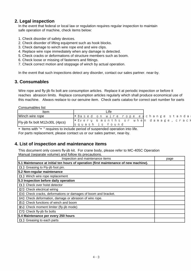
2. Legal inspectionIn the event that federal or local law or regulation requires regular inspection to maintain safe operation of machine, check items below:
1. Check disorder of safety devices.2. Check disorder of lifting equipment such as hook blocks.3. Check damage to winch wire rope end and wire clips. 4. Replace wire rope immediately when any damage is detected. 5. Check cracks or deformations of structure members such as boom. 6. Check loose or missing of fasteners and fittings.7. Check correct motion and stoppage of winch by actual operation.
In the event that such inspections detect any disorder, contact our sales partner. near-by.
3. Consumables
Consumables listItem
Winch wire rope
★Items with "★" requires to include period of suspended operation into life.For parts replacement, please contact us or our sales partner, near-by.
4. List of inspection and maintenance itemsThis document only covers fly-jib kit. For crane body, please refer to MC-405C Operation Manual (separate volume) and follow its precautions.
Inspection and maintenance items page5.1 Maintenance at initial ten hours of operation (first maintenance of new machine).[1] Greasing to Fly-jib foot pin.5.2 Non-regular maintenance[1] Winch wire rope replacement5.3 Inspection before daily operation[1] Check over hoist detector[2] Check electrical wiring[3] Check cracks, deformations or damages of boom and bracket.[4] Check deformation, damage or abrasion of wire rope.[5] Check functions of winch and boom[6] Check moment limiter (fly-jib mode)[7] Check fly-jib fix bolts5.4 Maintenance per every 250 hours[1] Greasing to each parts
★Based on wire rope exchange standardLife
Fly-jib fix bolt M12x30L (4pcs)
Wire rope and fly-jib fix bolt are consumption articles. Replace it at periodic inspection or before itreaches abrasion limits. Replace consumption articles regularly which shall produce economical use ofthis machine. Always replace to our genuine item. Check parts catalog for correct part number for parts
★Every 6 months or when damage, crack, orsquash is found
4-3
5. Procedure5.1 Maintenance at initial ten hours of operation (First maintenance of new machine).As a first maintenance of a new crane, perform below after initial 10 hours of operation.
[1] Greasing to each partsRefer to "5.4 Maintenance per every 250 hours" for places of maintenance and method.
5.2 Non-regular maintenance[2] Winch wire rope replacement
Wear a heavy duty working leather glove for wire rope replacement.
・For measurement of wire rope diameter, select the part of it where it passes sheave repeatedly.Measurement shall be made to three directions and average value of these three shall be used. (Measure several distant places, but not only one.) ・Replace aged wire rope even if it has not been in operation.
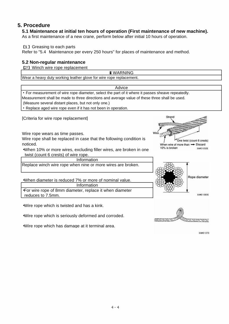
[Criteria for wire rope replacement]
Wire rope wears as time passes.
・When 10% or more wires, excluding filler wires, are broken in one twist (count 6 crests) of wire rope.
InformationReplace winch wire rope when nine or more wires are broken.
・When diameter is reduced 7% or more of nominal value.Information
・For wire rope of 8mm diameter, replace it when diameter reduces to 7.5mm.
・Wire rope which is twisted and has a kink.
・Wire rope which is seriously deformed and corroded.
・Wire rope which has damage at it terminal area.
Wire rope shall be replaced in case that the following condition isnoticed.
� WARNING
Advice
4-4
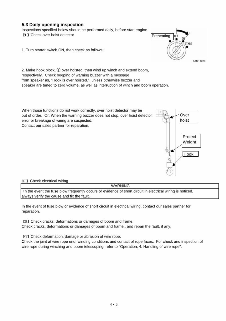
5.3 Daily opening inspectionInspections specified below should be performed daily, before start engine. [1] Check over hoist detector
1. Turn starter switch ON, then check as follows:
2. Make hook block, ① over hoisted, then wind up winch and extend boom,respectively. Check beeping of warning buzzer with a messagefrom speaker as, "Hook is over hoisted.", unless otherwise buzzer and speaker are tuned to zero volume, as well as interruption of winch and boom operation.
When those functions do not work correctly, over hoist detector may be out of order. Or, When the warning buzzer does not stop, over hoist detectorerror or breakage of wiring are suspected. Contact our sales partner for reparation.
[2] Check electrical wiring
・In the event the fuse blow frequently occurs or evidence of short circuit in electrical wiring is noticed,always verify the cause and fix the fault.
In the event of fuse blow or evidence of short circuit in electrical wiring, contact our sales partner for reparation.
[3] Check cracks, deformations or damages of boom and frame.Check cracks, deformations or damages of boom and frame., and repair the fault, if any.
[4] Check deformation, damage or abrasion of wire rope.Check the joint at wire rope end, winding conditions and contact of rope faces. For check and inspection of wire rope during winching and boom telescoping, refer to "Operation, 4. Handling of wire rope".
WARNING
Hook
ProtectWeight
Overhoistdetector
Preheating
4-5
[5] Check functions of winch and boom
At the performance of function check for winch and boom, ensure the safety such that hook and boom would not interfere with any personnel nor object.
1. Check abnormal noise from boom, hook and any area of wire rope during crane operation.
2. Operate crane without load and check loose and missing of each bolt.
3. Check hook for deformation, abnormal noise from bearing and correct function of wire rope latch, ①.
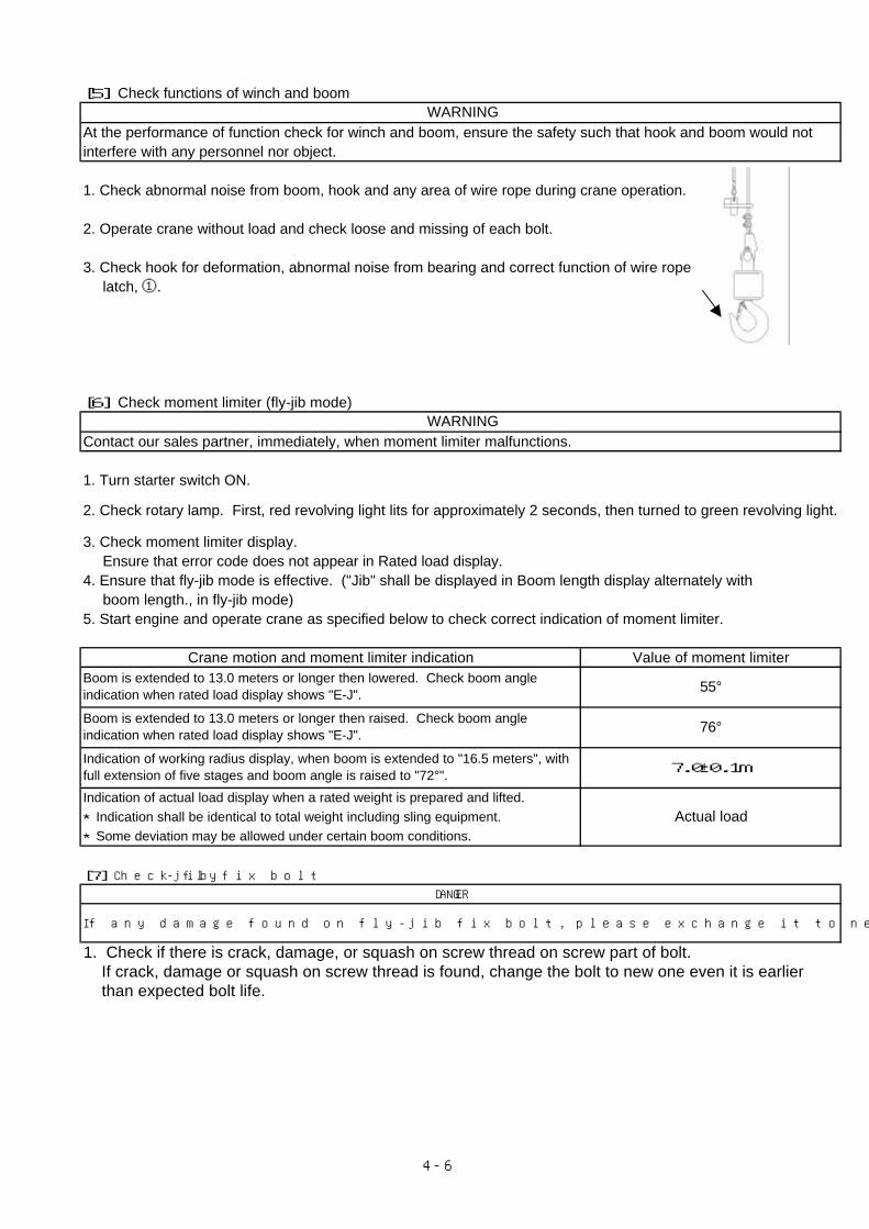
[6] Check moment limiter (fly-jib mode)
Contact our sales partner, immediately, when moment limiter malfunctions.
1. Turn starter switch ON.
3. Check moment limiter display. Ensure that error code does not appear in Rated load display.4. Ensure that fly-jib mode is effective. ("Jib" shall be displayed in Boom length display alternately with boom length., in fly-jib mode)5. Start engine and operate crane as specified below to check correct indication of moment limiter.
Crane motion and moment limiter indication Value of moment limiter
Indication of actual load display when a rated weight is prepared and lifted. ★Indication shall be identical to total weight including sling equipment.★Some deviation may be allowed under certain boom conditions.
[7] Check fly-jib fix bolt
1. Check if there is crack, damage, or squash on screw thread on screw part of bolt. If crack, damage or squash on screw thread is found, change the bolt to new one even it is earlier than expected bolt life.
DANGER
If any damage found on fly-jib fix bolt, please exchange it to new one right away. Breakage of bolt cause fly-jib to fall off.
WARNING
WARNING
Actual load
Boom is extended to 13.0 meters or longer then raised. Check boom angleindication when rated load display shows "E-J". 76°
Indication of working radius display, when boom is extended to "16.5 meters", withfull extension of five stages and boom angle is raised to "72°". 7.0±0.1m
2. Check rotary lamp. First, red revolving light lits for approximately 2 seconds, then turned to green revolving light.
55°Boom is extended to 13.0 meters or longer then lowered. Check boom angleindication when rated load display shows "E-J".
4-6
5.4 Maintenance per every 250 hours
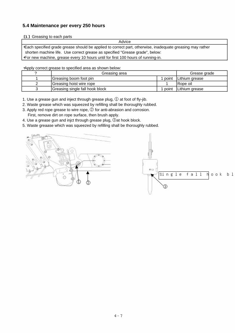
[1] Greasing to each parts
・Each specified grade grease should be applied to correct part, otherwise, inadequate greasing may rather shorten machine life. Use correct grease as specified "Grease grade", below:・For new machine, grease every 10 hours until for first 100 hours of running-in.
・Apply correct grease to specified area as shown below:? Greasing area Grease grade1 Greasing boom foot pin 1 point Lithium grease2 Greasing hoist wire rope 1 Rope oil3 Greasing single fall hook block 1 point Lithium grease
1. Use a grease gun and inject through grease plug, ① at foot of fly-jib.2. Waste grease which was squeezed by refilling shall be thoroughly rubbed. 3. Apply red rope grease to wire rope, ② for anti-abrasion and corrosion. First, remove dirt on rope surface, then brush apply.4. Use a grease gun and injct through grease plug, ③at hook block.5. Waste greaase which was squeezed by refilling shall be thoroughly rubbed.
Advice
① ②
Single fall hook block
③
4-7
MAEDA MINI-CRAWLER CRANE MC-405C FLY JIB OPERATION MANUAL Document No: 104FE-OM0709-00 First edition: September 26 2007
Issued by Maeda Seisakusyo Co., Ltd. 1095 Onbegawa, Shinonoi Nagano, Nagano 388-8522, Japan
No part of this manual can be reproduced in any from without permission