Embed Size (px)
Citation preview

Owner’s Operation& Installation Manual
1500 lb Yacht Crane
STEELHEADMARINE


STEELHEAD MARINE: 1500 lb Yacht Crane Installation Manual
Table of Contents
Required Equipment and ToolsSupplied Equipment List .....................................................................1Optional Equipment List......................................................................1Recommended Materials (not supplied) ...............................................2Required Tools...................................................................................2
Planning the InstallationChoosing the Installation Method.........................................................3Locating the Crane System.................................................................3Reach Table ......................................................................................4
Installation ProcedureInstalling the Standpipe ......................................................................5Hydraulic and Electrical Connections....................................................7Completing and Testing the Installation ................................................9
Operating InstructionsWARNING: REVIEW BEFORE OPERATING..........................................10Operating Instructions......................................................................10Crane Storage.................................................................................12Maintenance ...................................................................................13Troubleshooting ...............................................................................14
SpecificationsElectrical System.............................................................................16Hydraulic System.............................................................................16Fittings, Hardware, and Cables .........................................................16Equipment Dimensions .....................................................................16
Warranty ........................................................................................17
Servicing Dealers .............................................................................19
Distributors.....................................................................................21
AppendixManifold..........................................................................................22Wiring Diagram...............................................................................24
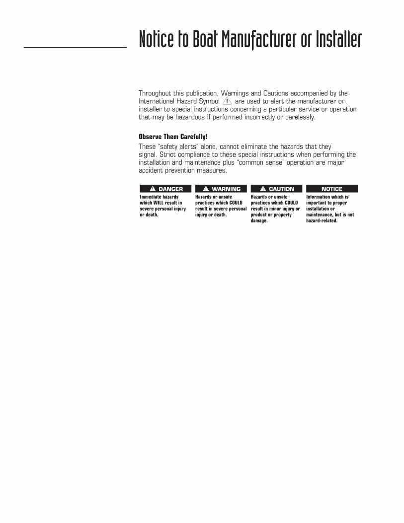
Throughout this publication, Warnings and Cautions accompanied by theInternational Hazard Symbol are used to alert the manufacturer orinstaller to special instructions concerning a particular service or operationthat may be hazardous if performed incorrectly or carelessly.
Observe Them Carefully!These “safety alerts” alone, cannot eliminate the hazards that they signal. Strict compliance to these special instructions when performing theinstallation and maintenance plus “common sense” operation are majoraccident prevention measures.
Notice to Boat Manufacturer or Installer
Hazards or unsafepractices which COULDresult in minor injury orproduct or propertydamage.
CAUTIONHazards or unsafepractices which COULDresult in severe personalinjury or death.
WARNINGImmediate hazardswhich WILL result insevere personal injuryor death.
DANGERInformation which isimportant to properinstallation ormaintenance, but is nothazard-related.
NOTICE
STEELHEAD MARINE: 1500 lb Yacht Crane Installation Manual
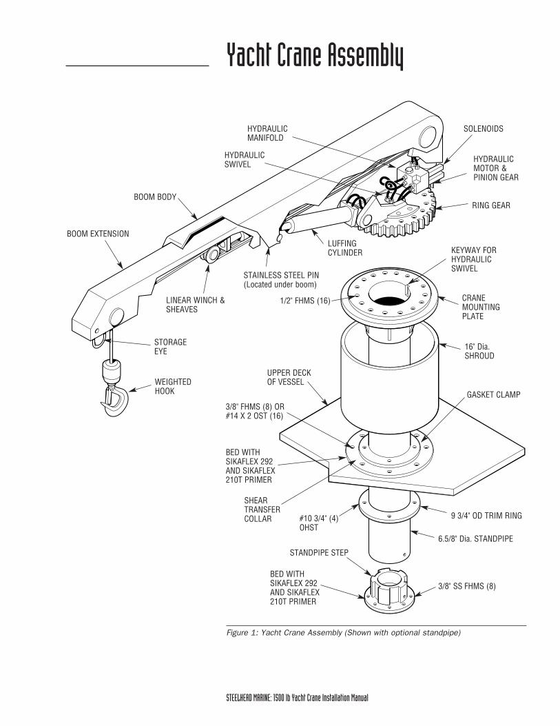
Yacht Crane Assembly
Figure 1: Yacht Crane Assembly (Shown with optional standpipe)
CRANEMOUNTINGPLATE
KEYWAY FORHYDRAULICSWIVEL
16" Dia.SHROUD
6.5/8" Dia. STANDPIPE
3/8" SS FHMS (8)
STANDPIPE STEP
1/2" FHMS (16)
GASKET CLAMP
9 3/4" OD TRIM RING#10 3/4" (4)OHST
BOOM EXTENSION
BOOM BODY
HYDRAULICMANIFOLD
STAINLESS STEEL PIN(Located under boom)
STORAGEEYE
WEIGHTEDHOOK
RING GEAR
HYDRAULICMOTOR &PINION GEAR
SOLENOIDS
HYDRAULICSWIVEL
LUFFINGCYLINDER
LINEAR WINCH &SHEAVES
UPPER DECKOF VESSEL
SHEARTRANSFERCOLLAR
3/8" FHMS (8) OR #14 X 2 OST (16)
BED WITH SIKAFLEX 292 AND SIKAFLEX 210T PRIMER
BED WITH SIKAFLEX 292 AND SIKAFLEX 210T PRIMER

STEELHEAD MARINE: 1500 lb Yacht Crane Installation Manualc-iv
STEELHEAD MARINE: 1500 lb Yacht Crane Installation Manual 1
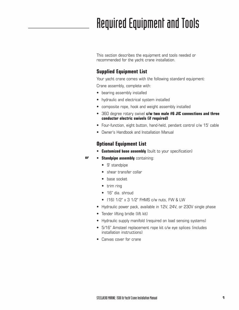
Required Equipment and Tools
This section describes the equipment and tools needed or recommended for the yacht crane installation.
Supplied Equipment List Your yacht crane comes with the following standard equipment:
Crane assembly, complete with:
• bearing assembly installed
• hydraulic and electrical system installed
• composite rope, hook and weight assembly installed
• 360 degree rotary swivel c/w two male #6 JIC connections and threeconductor electric swivels (if required)
• Four-function, eight button, hand-held, pendant control c/w 15' cable
• Owner's Handbook and Installation Manual
Optional Equipment List • Customized base assembly (built to your specification)
• Standpipe assembly containing:
• 9' standpipe
• shear transfer collar
• base socket
• trim ring
• 16" dia. shroud
• (16) 1/2" x 3 1/2" FHMS c/w nuts, FW & LW
• Hydraulic power pack, available in 12V, 24V, or 230V single phase
• Tender lifting bridle (lift kit)
• Hydraulic supply manifold (required on load sensing systems)
• 5/16" Amsteel replacement rope kit c/w eye splices (includesinstallation instructions)
• Canvas cover for crane
or
STEELHEAD MARINE: 1500 lb Yacht Crane Installation Manual2
Recommended Materials (not supplied)You will need all or most of the following materials for the craneinstallation:
• 16 - #14 x 2 OHST screws, or,
• 8- 3/8-16 FHMS for thru-bolting (sheer transfer collar)
• 4 - #10 x 3/4 OHST screws (trim ring)
• Sikaflex 292, Sikaflex 210T primer
• anti-corrosion paste (Tef-Gel)
• marine corrosion control grease
• heat-shrink-type electrical connectors
• 16/3 electrical cable, length as required
• electrical breakers
• deck pad-eye
Required ToolsYou should have the following tools on hand for installation:
• tape measure
• masking tape
• caulking gun
• drill motor
• portable band saw, or Sawzall power saw
• Phillips screwdrivers
• utility knife
• level
• holesaw (3 5/8" and 7")
• assorted drill bits (3/16", 1/4", 5/16", 3/8")
• 3/8"-16 tap and handle (optional)
• assorted metal-working files
• wire strippers/cutters
• heat shrink tubing and gun
• wet/dry vacuum
• safety goggles and/or face shield
STEELHEAD MARINE: 1500 lb Yacht Crane Installation Manual 3
Planning the Installation
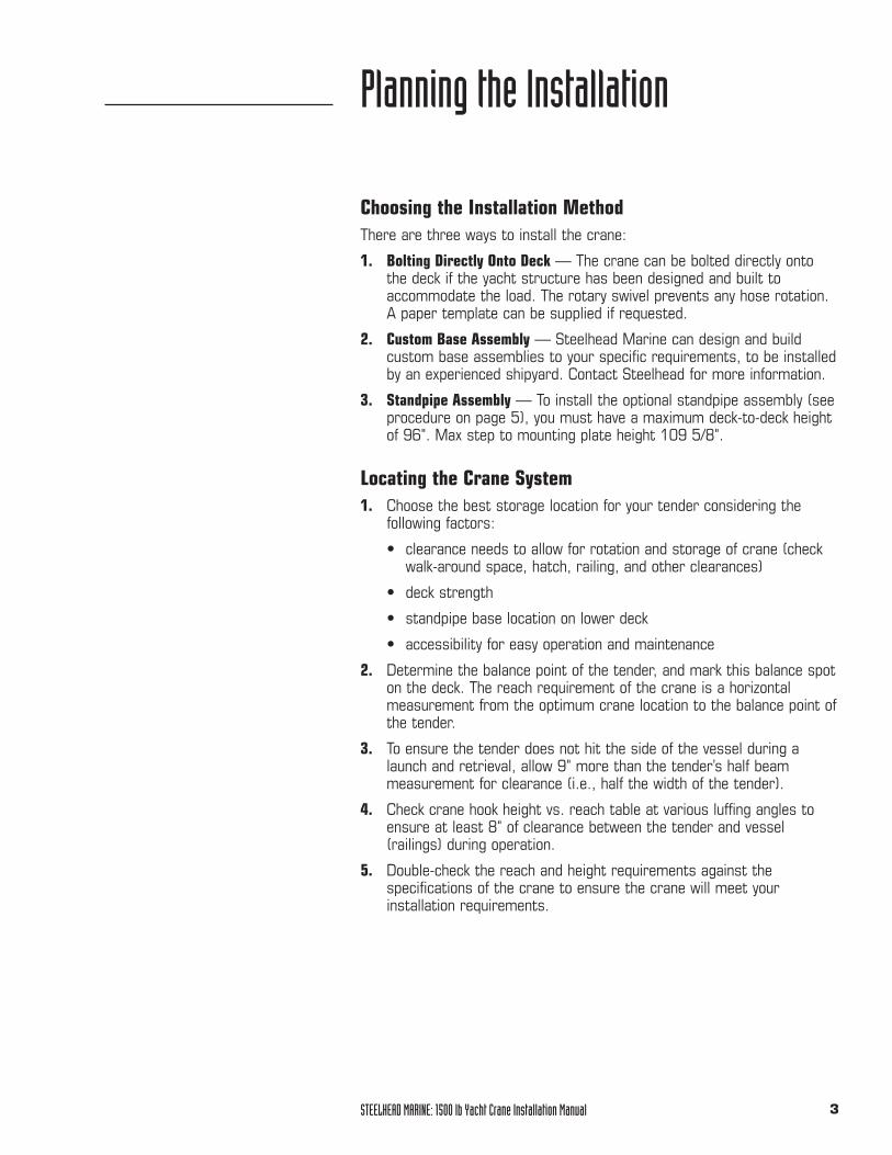
Choosing the Installation MethodThere are three ways to install the crane:
1. Bolting Directly Onto Deck — The crane can be bolted directly onto the deck if the yacht structure has been designed and built toaccommodate the load. The rotary swivel prevents any hose rotation.A paper template can be supplied if requested.
2. Custom Base Assembly — Steelhead Marine can design and buildcustom base assemblies to your specific requirements, to be installedby an experienced shipyard. Contact Steelhead for more information.
3. Standpipe Assembly — To install the optional standpipe assembly (seeprocedure on page 5), you must have a maximum deck-to-deck heightof 96". Max step to mounting plate height 109 5/8".
Locating the Crane System1. Choose the best storage location for your tender considering the
following factors:
• clearance needs to allow for rotation and storage of crane (checkwalk-around space, hatch, railing, and other clearances)
• deck strength
• standpipe base location on lower deck
• accessibility for easy operation and maintenance
2. Determine the balance point of the tender, and mark this balance spoton the deck. The reach requirement of the crane is a horizontalmeasurement from the optimum crane location to the balance point ofthe tender.
3. To ensure the tender does not hit the side of the vessel during alaunch and retrieval, allow 9" more than the tender’s half beammeasurement for clearance (i.e., half the width of the tender).
4. Check crane hook height vs. reach table at various luffing angles toensure at least 8" of clearance between the tender and vessel(railings) during operation.
5. Double-check the reach and height requirements against thespecifications of the crane to ensure the crane will meet yourinstallation requirements.
STEELHEAD MARINE: 1500 lb Yacht Crane Installation Manual4
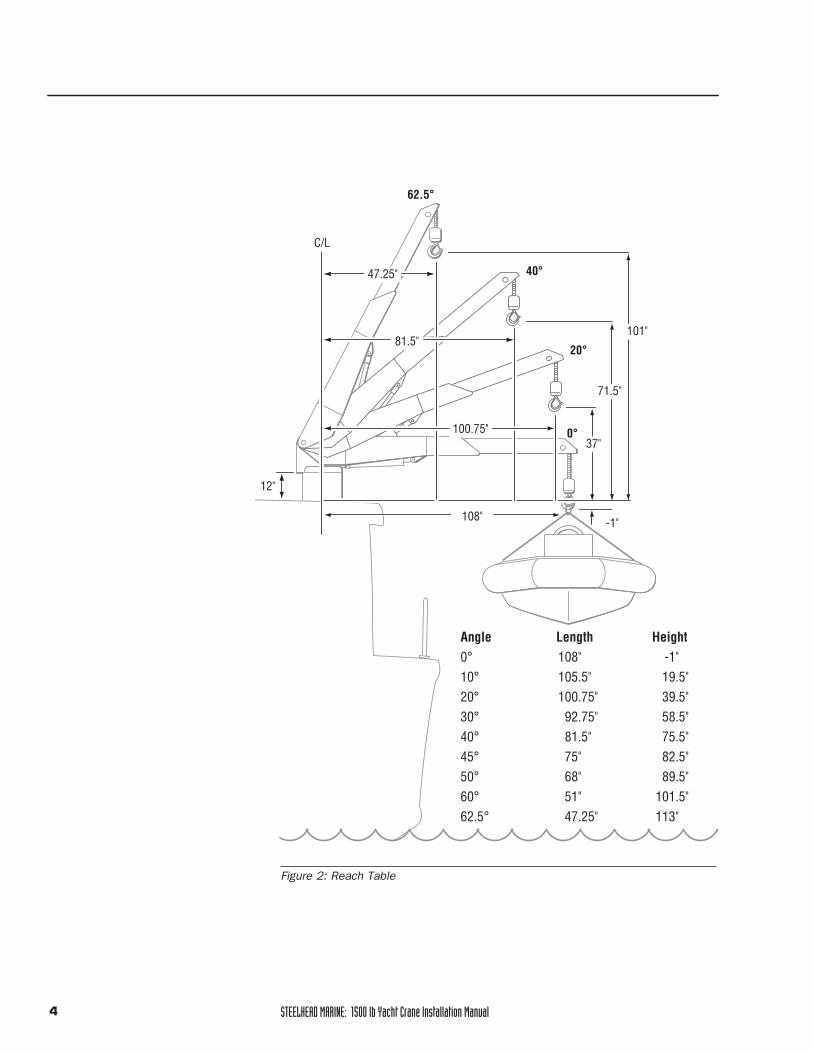
Figure 2: Reach Table
37"
-1"
71.5"
101"
40°
20°
0°
62.5°
47.25"
C/L
81.5"
100.75"
108"
Angle Length Height0° 108" -1"10° 105.5" 19.5"20° 100.75" 39.5"30° 92.75" 58.5"40° 81.5" 75.5"45° 75" 82.5"50° 68" 89.5"60° 51" 101.5"62.5° 47.25" 113"
12"
STEELHEAD MARINE: 1500 lb Yacht Crane Installation Manual 5
Installation Procedure
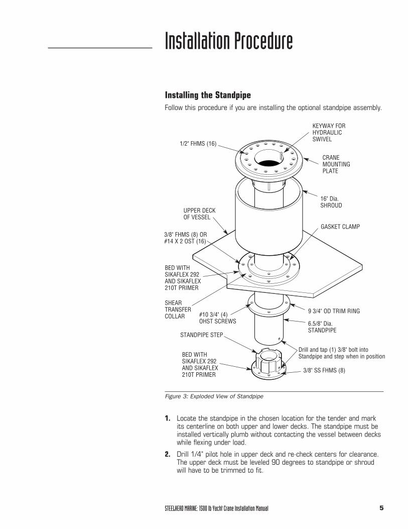
Figure 3: Exploded View of Standpipe
Installing the StandpipeFollow this procedure if you are installing the optional standpipe assembly.
1. Locate the standpipe in the chosen location for the tender and markits centerline on both upper and lower decks. The standpipe must beinstalled vertically plumb without contacting the vessel between deckswhile flexing under load.
2. Drill 1/4" pilot hole in upper deck and re-check centers for clearance.The upper deck must be leveled 90 degrees to standpipe or shroudwill have to be trimmed to fit.
CRANEMOUNTINGPLATE
16" Dia.SHROUD
6.5/8" Dia.STANDPIPE
Drill and tap (1) 3/8" bolt intoStandpipe and step when in position
STANDPIPE STEP
UPPER DECKOF VESSEL
SHEARTRANSFERCOLLAR
KEYWAY FORHYDRAULICSWIVEL
3/8" SS FHMS (8)
1/2" FHMS (16)
3/8" FHMS (8) OR #14 X 2 OST (16)
BED WITH SIKAFLEX 292 AND SIKAFLEX210T PRIMER
BED WITH SIKAFLEX 292 AND SIKAFLEX 210T PRIMER
GASKET CLAMP
9 3/4" OD TRIM RING#10 3/4" (4)OHST SCREWS
STEELHEAD MARINE: 1500 lb Yacht Crane Installation Manual6
3. Drill 7" hole through upper deck.
4. Mount shear transfer collar to upper deck by drilling through theupper deck:
• eight 3/8" clearance holes for thru-bolting, OR
• sixteen 3/16" pilot holes for #14 screws
5. Clean deck surface and mount shear transfer collar by bedding withSikaflex 292 and Sikaflex 210T Primer and installing fastenersthrough holes on 16" diameter base of collar (using bolts or screwsas per Step 4).
6. Seal deck core material and clean off excess sealant.
7. With assistance from below, lower standpipe through collar to lowerdeck. Mark location of standpipe step on lower deck.
8. On lower deck, drill 3 5/8" hole through center of standpipe steplocation for standpipe step spigot.
9. Drill eight 3/8" mounting holes.
10. Seal deck core material as directed by shipyard, chock standpipe stepspigot with FRP filler material and bed standpipe step with Sikaflex292 and Sikaflex 210T Primer. The standpipe must be square to thestandpipe step or it will not slide completely into place.
11 Install step fasteners to secure step onto deck floor.
12. With assistance from below, reinstall standpipe, sliding trim ring overbottom of standpipe before placing over step (the trim ring will attachto ceiling of lower deck). Ensure that the standpipe contacts standpipestep evenly all the way around, with outer lip of step protruding.
13. Drill and tap 3/8" bolt through standpipe into step to lock standpipeinto position.
14. Secure collar clamp and gasket to shear transfer collar by tighteningthe eight 3/8" bolts evenly. These bolts compress sealing gasket oncollar and lock standpipe into position on upper deck.
15. Mount trim ring to ceiling of lower deck using four screws.
NOTICEThere are three parts to the sheartransfer collar: a 16" diameter base, arubber gasket, and an 11" diametergasket clamp.
NOTICEWhen the standpipe is installedcorrectly, there will be a 1/8" gapbetween the shroud and the sheartransfer collar. The shroud will bescrewed to the underside of the cranemounting plate, but not until the end ofthe installation. You must take themeasurement described in Step 7when the standpipe is placed over topof the standpipe step on the lowerdeck. The measurement must be 1/8"longer than the length of the shroud(11 1/4") and the bottom of thestandpipe will need to be trimmedaccordingly.
NOTICEThe standpipe must be square to thestandpipe step or it will not slidecompletely into place.
STEELHEAD MARINE: 1500 lb Yacht Crane Installation Manual 7
Hydraulic and Electrical ConnectionsTo install the crane's hydraulic and/or electrical connections:
1. Lead two #6 hydraulic lines from ship’s hydraulics (or power pack), totop of standpipe mounting plate. Add 12" extra length for connection.
2. Lead 3/16 electrical wire from ship's main breaker and power pack orhydraulic manifold to crane mounting plate. Again, add 12" extralength for connections.
3. Remove access covers from crane assembly base.
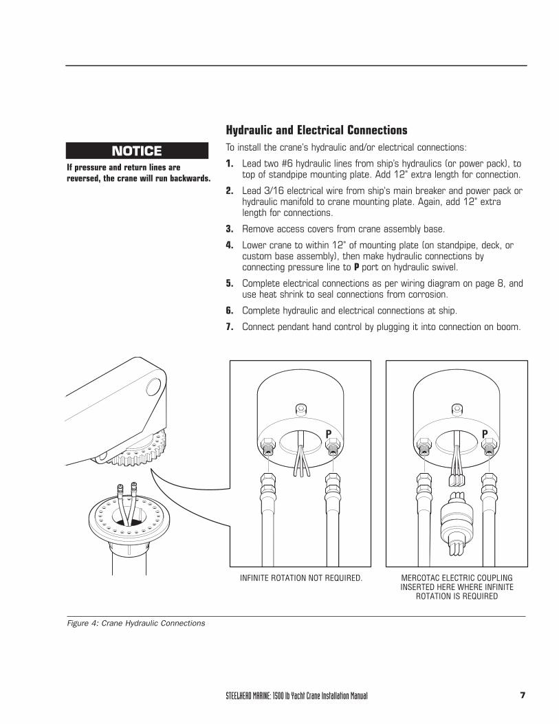
4. Lower crane to within 12" of mounting plate (on standpipe, deck, orcustom base assembly), then make hydraulic connections byconnecting pressure line to P port on hydraulic swivel.
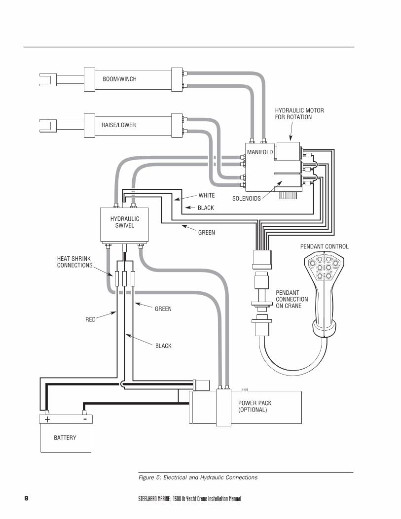
5. Complete electrical connections as per wiring diagram on page 8, anduse heat shrink to seal connections from corrosion.
6. Complete hydraulic and electrical connections at ship.
7. Connect pendant hand control by plugging it into connection on boom.
Figure 4: Crane Hydraulic Connections
P P
MERCOTAC ELECTRIC COUPLINGINSERTED HERE WHERE INFINITE
ROTATION IS REQUIRED
INFINITE ROTATION NOT REQUIRED.
NOTICEIf pressure and return lines arereversed, the crane will run backwards.
STEELHEAD MARINE: 1500 lb Yacht Crane Installation Manual8
Figure 5: Electrical and Hydraulic Connections
ININ OUTOUTIN OUT
EXTEND
BOOM
WINCH
UP DN
LEFT RIGHT
BOOM/WINCH
RAISE/LOWER
HYDRAULICSWIVEL
MANIFOLD
HYDRAULIC MOTORFOR ROTATION
WHITE
BLACK
GREEN
RED
BLACK
HEAT SHRINKCONNECTIONS
+ -
GREEN
POWER PACK (OPTIONAL)
PENDANT CONTROL
PENDANTCONNECTIONON CRANE
BATTERY
SOLENOIDS
STEELHEAD MARINE: 1500 lb Yacht Crane Installation Manual 9
Completing and Testing the InstallationTo complete and test the installation of the crane:1. Seal between mounting plate and crane bearing with silicone sealant to
prevent water from leaking into boat.2. Lower crane onto mounting plate, ensuring that the hydraulic swivel
fits correctly into the 4 3/4" diameter hole and retaining notch incenter of mounting plate.
3. Install 16 mounting bolts, 1/2" x 3", and tighten bolts4. Retract both hydraulic cylinders. Fill hydraulic reservoir tank with
AW 32 Hydraulic Oil to within 2" of the top. 5. Test crane as follows:
• Turn breakers on momentarily. • Ensure power unit turns on.• Check all wiring. • Check hydraulic source and ensure correct pressure from pressure port.• Turn on control breaker.• Lightly touch each button on the pendant hand control to make sure
crane moves appropriately.6. When systems are confirmed correct, recheck oil level in reservoir
and refill to 2" level. 7. Rotate crane 90° and turn power off. 8. Install six remaining mounting bolts (1/2" x 3") on crane mounting
plate and tighten as previously directed. (Crane always covers six bolts, so crane must be rotated to expose them.)
9. Reinstall crane access covers.10. Slide shroud over the crane mounting plate and attach it to the
underside of the plate using 8/32" screws. Use Tef-Gel where stainless screws contact painted aluminum surfaces to prevent paintblistering and corrosion.
11. During shipment, air may have collected in hydraulic system. To bleed,operate all boom functions through their full travel capacity 3 or 4 times,using pendant hand control. This will remove any air in the system.
12. Recheck oil level in reservoir to ensure 2" level has been maintained.
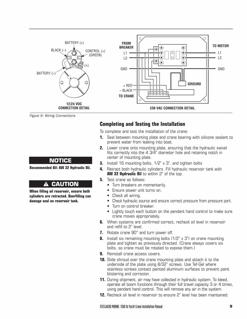
12/24 VDCCONNECTION DETAIL
Figure 6: Wiring Connections
TO MOTOR
L1L2
GND
L1L2
GND
FROM BREAKER
GROUND+ RED– BLACK
BATTERY (+)
CONTROL (+) (GREEN)
BATTERY (–)
BLACK (–)
TO CRANE
(+)
230 VAC CONNECTION DETAIL
CAUTIONWhen filling oil reservoir, ensure bothcylinders are retracted. Overfilling candamage seal on reservoir tank.
NOTICERecommended Oil: AW 32 Hydraulic Oil.
STEELHEAD MARINE: 1500 lb Yacht Crane Installation Manual10
Operating Instructions
Misuse of the crane may result in injury or death. Always follow carefully these safety cautions:
• Do not begin hoisting until the boom has been fully extended and thestainless steel plunger locked into position.
• Never load the crane system beyond its capacity of 1500 lb.
• Be sure the area around and under the tender is clear of people andobstacles before lowering, including lower decks and water level.
• Remove all cargo and excess water from the tender before raising or lowering.
• Ensure all passengers leave tender before raising and lowering—thiscrane is not a personnel lift.
• Position the crane directly over the load when operating—the crane isdesigned for vertical hoisting only.
• Do not launch or retrieve a tender in rough sea conditions, or while underway.
• Be aware that yachts tend to list when launching a tender. Use cautionwhen rotating a load.
• Do not allow children to operate the crane.
• Keep hands away from all moving parts.
• Turn the crane's power supply off when not in use.
• Detach crane from tender and retract boom to stow.
• Detach pendant control when not in use.
Operating Instructions1. Turn on hydraulic supply by:
• activating the ship’s hydraulics, OR
• turning on the ship's main breaker to supply the crane's power pack
2. Turn on the crane's control power by flipping the 4-amp breaker.
3. Remove waterproof plug on crane body and plug in pendant control.
4. Extend boom to operational length by pressing the Up button for thewinch on pendant control [Item 5 Figure 7] until stainless plungersnaps into locked position.
5. Disconnect weighted hook from storage eye and allow it to hang freely.
6. Attach the tender's lifting bridle to the weighted hook. Using thependant control (Figure 7), position the lifting bridle to enableattachment to the tender.
7. Raise the lifting bridle just enough to remove any slack from thecables. Check all attachments to the tender.
WARNINGREVIEW BEFORE OPERATING
STEELHEAD MARINE: 1500 lb Yacht Crane Installation Manual 11
8. Remove the tender's attachments to the deck, and ensure thetender's drain plug is installed.
9. Attach the handling lines to the bow and stern of the tender.
10. Raise the tender high enough to clear all deck obstructions and railings.
11. Rotate the load outboard, controlling the tender position with bow andstern lines.
12. Lower the load to the water. Pay out enough cable so that the tenderdoes not load the cable and crane as it rides waves or swells.
13. Using the load-handling lines, pull the tender to a point near the vesselwhere it may be boarded. Disconnect the lifting bridle from the tender.
14. Secure the weighted hook so that it does not swing into the side ofthe vessel.
IN OUTIN OUT
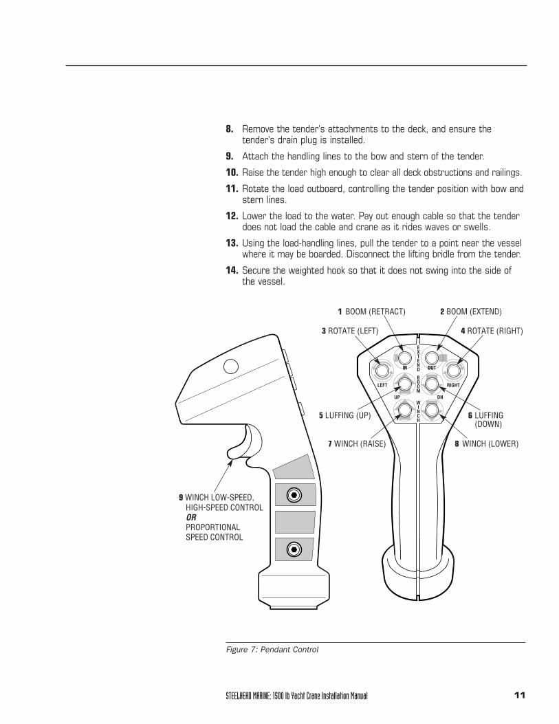
EXTEND
BOOM
WINCH
UP DN
LEFT RIGHT
IN OUT
Figure 7: Pendant Control
6 LUFFING (DOWN)
5 LUFFING (UP)
4 ROTATE (RIGHT)3 ROTATE (LEFT)
1 BOOM (RETRACT) 2 BOOM (EXTEND)
8 WINCH (LOWER)7 WINCH (RAISE)
9 WINCH LOW-SPEED,HIGH-SPEED CONTROLORPROPORTIONAL SPEED CONTROL
STEELHEAD MARINE: 1500 lb Yacht Crane Installation Manual12
Crane StorageTo properly store the crane after use:
1. Luff crane to horizontal position.
2. Hoist cable to maximum lift.
3. Attach weighted hook to storage eye on the underside of the boom tip.
4. Pull down on spring loaded locking pin and retract boom to storagelength.
5. Detach pendant control and screw waterproof cap in place.
Crane Deployment1. Extend boom until locking pin snaps into engaged position.
2. Remove hook from storage bail and let hang freely.
3. Crane is ready for hoisting.
CAUTION
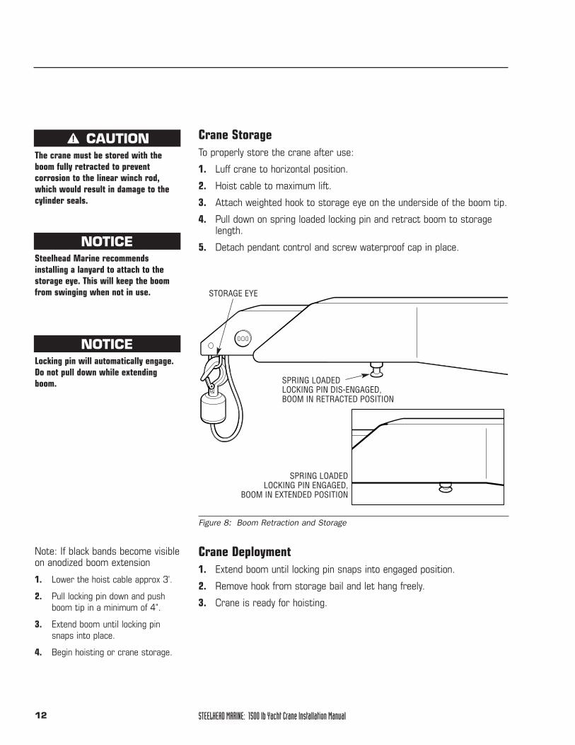
STORAGE EYE
SPRING LOADED LOCKING PIN DIS-ENGAGED, BOOM IN RETRACTED POSITION
SPRING LOADED LOCKING PIN ENGAGED,
BOOM IN EXTENDED POSITION
Figure 8: Boom Retraction and Storage
Note: If black bands become visibleon anodized boom extension
1. Lower the hoist cable approx 3'.
2. Pull locking pin down and pushboom tip in a minimum of 4".
3. Extend boom until locking pinsnaps into place.
4. Begin hoisting or crane storage.
The crane must be stored with theboom fully retracted to preventcorrosion to the linear winch rod,which would result in damage to thecylinder seals.
NOTICESteelhead Marine recommendsinstalling a lanyard to attach to thestorage eye. This will keep the boomfrom swinging when not in use.
NOTICELocking pin will automatically engage.Do not pull down while extendingboom.
STEELHEAD MARINE: 1500 lb Yacht Crane Installation Manual 13
Maintenance
Safety CautionsDeath, injury, or damage may result if the crane’s cable is not inspectedregularly, and replaced as needed.
Counter balances have been factory set for optimal performance, cranesafety may be jeopardized by unauthorized adjustments.
If the boom is in a 62° position during maintenance, the suppliedaluminum luffing rod support must be installed to prevent injury to personnel.
WARNINGREVIEW BEFORE COMMENCINGMAINTENANCE
Monthly Quarterly Annually As required
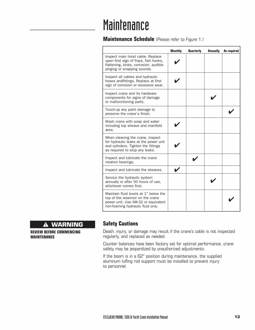
Inspect main hoist cable. Replace upon first sign of frays, fish hooks,flattening, kinks, corrosion, audiblepinging or snapping sounds.
Inspect all cables and hydraulic hoses andfittings. Replace at first sign of corrosion or excessive wear.
Inspect crane and its hardware components for signs of damage or malfunctioning parts.
Touch-up any paint damage to preserve the crane’s finish.
Wash crane with soap and water including top sheave and manifold area.
When cleaning the crane, inspect for hydraulic leaks at the power unit and cylinders. Tighten the fittings as required to stop any leaks.
Inspect and lubricate the crane rotation bearings.
Inspect and lubricate the sheaves.
Service the hydraulic system annually or after 50 hours of use, whichever comes first.
Maintain fluid levels at 1" below the top of the reservoir on the crane power unit. Use AW-32 or equivalent non-foaming hydraulic fluid only.
Maintenance Schedule (Please refer to Figure 1.)
✔
✔
✔
✔
✔
✔
✔
✔
✔
✔
STEELHEAD MARINE: 1500 lb Yacht Crane Installation Manual14
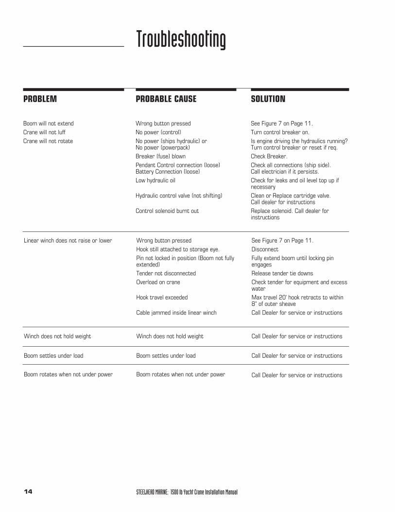
Troubleshooting
PROBLEM PROBABLE CAUSE SOLUTION
Boom will not extendCrane will not luffCrane will not rotate
Wrong button pressedNo power (control) No power (ships hydraulic) or No power (powerpack)Breaker (fuse) blownPendant Control connection (loose)Battery Connection (loose)Low hydraulic oil
Hydraulic control valve (not shifting)
Control solenoid burnt out
See Figure 7 on Page 11.Turn control breaker on.Is engine driving the hydraulics running?Turn control breaker or reset if req.Check Breaker.Check all connections (ship side). Call electrician if it persists.Check for leaks and oil level top up if necessaryClean or Replace cartridge valve.Call dealer for instructionsReplace solenoid. Call dealer for instructions
Linear winch does not raise or lower Wrong button pressedHook still attached to storage eye.Pin not locked in position (Boom not fullyextended)Tender not disconnectedOverload on crane
Hook travel exceeded
Cable jammed inside linear winch
See Figure 7 on Page 11.Disconnect Fully extend boom until locking pinengagesRelease tender tie downsCheck tender for equipment and excesswaterMax travel 20' hook retracts to within8" of outer sheaveCall Dealer for service or instructions
Winch does not hold weight
Boom settles under load
Boom rotates when not under power
Winch does not hold weight
Boom settles under load
Boom rotates when not under power
Call Dealer for service or instructions
Call Dealer for service or instructions
Call Dealer for service or instructions
STEELHEAD MARINE: 1500 lb Yacht Crane Installation Manual 15
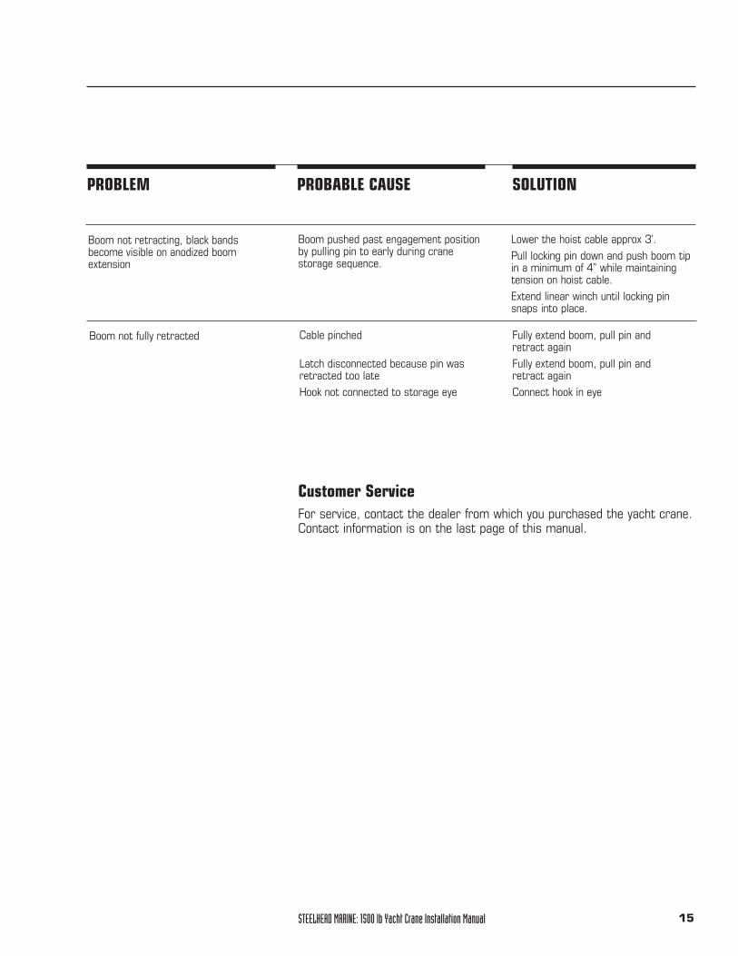
PROBLEM PROBABLE CAUSE SOLUTION
Boom not retracting, black bandsbecome visible on anodized boom extension
Boom pushed past engagement positionby pulling pin to early during crane storage sequence.
Lower the hoist cable approx 3'.Pull locking pin down and push boom tipin a minimum of 4” while maintainingtension on hoist cable.Extend linear winch until locking pinsnaps into place.
Boom not fully retracted Cable pinched
Latch disconnected because pin wasretracted too lateHook not connected to storage eye
Fully extend boom, pull pin and retract againFully extend boom, pull pin and retract againConnect hook in eye
Customer ServiceFor service, contact the dealer from which you purchased the yacht crane.Contact information is on the last page of this manual.
STEELHEAD MARINE: 1500 lb Yacht Crane Installation Manual16
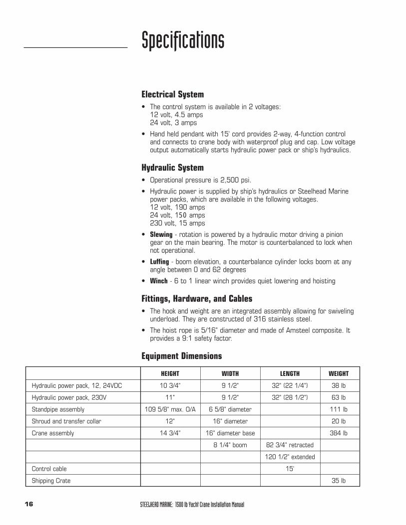
Electrical System• The control system is available in 2 voltages:
12 volt, 4.5 amps 24 volt, 3 amps
• Hand held pendant with 15' cord provides 2-way, 4-function controland connects to crane body with waterproof plug and cap. Low voltageoutput automatically starts hydraulic power pack or ship’s hydraulics.
Hydraulic System• Operational pressure is 2,500 psi.
• Hydraulic power is supplied by ship’s hydraulics or Steelhead Marinepower packs, which are available in the following voltages. 12 volt, 190 amps24 volt, 150 amps 230 volt, 15 amps
• Slewing - rotation is powered by a hydraulic motor driving a piniongear on the main bearing. The motor is counterbalanced to lock whennot operational.
• Luffing - boom elevation, a counterbalance cylinder locks boom at anyangle between 0 and 62 degrees
• Winch - 6 to 1 linear winch provides quiet lowering and hoisting
Fittings, Hardware, and Cables• The hook and weight are an integrated assembly allowing for swiveling
underload. They are constructed of 316 stainless steel.
• The hoist rope is 5/16" diameter and made of Amsteel composite. Itprovides a 9:1 safety factor.
Equipment Dimensions
Specifications
HEIGHT WIDTH LENGTH WEIGHT
Hydraulic power pack, 12, 24VDC 10 3/4" 9 1/2" 32" (22 1/4") 38 lb
Hydraulic power pack, 230V 11" 9 1/2" 32" (28 1/2") 63 lb
Standpipe assembly 109 5/8" max. O/A 6 5/8" diameter 111 lb
Shroud and transfer collar 12" 16" diameter 20 lb
Crane assembly 14 3/4" 16" diameter base 384 lb
8 1/4" boom 82 3/4" retracted
120 1/2" extended
Control cable 15'
Shipping Crate 35 lb
STEELHEAD MARINE: 1500 lb Yacht Crane Installation Manual 17
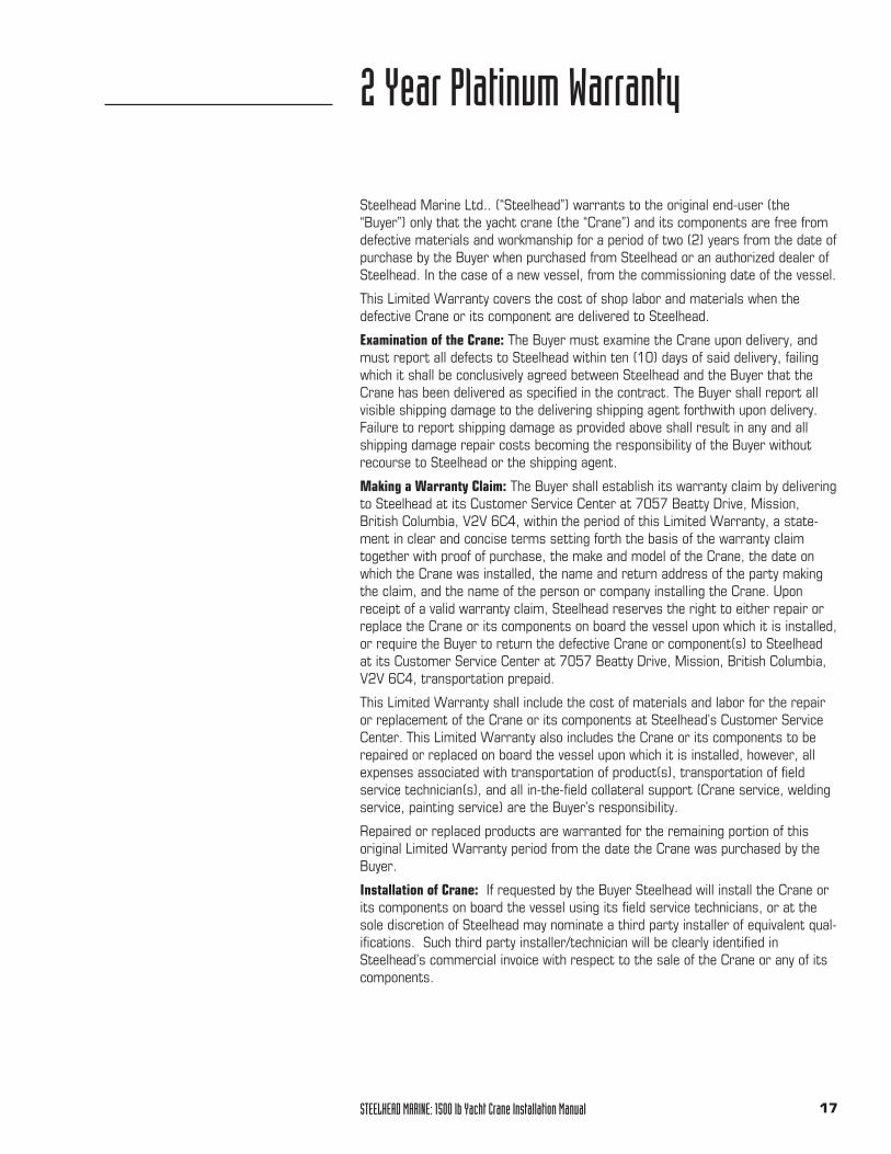
Steelhead Marine Ltd.. (“Steelhead”) warrants to the original end-user (the“Buyer”) only that the yacht crane (the “Crane”) and its components are free fromdefective materials and workmanship for a period of two (2) years from the date ofpurchase by the Buyer when purchased from Steelhead or an authorized dealer ofSteelhead. In the case of a new vessel, from the commissioning date of the vessel.
This Limited Warranty covers the cost of shop labor and materials when thedefective Crane or its component are delivered to Steelhead.
Examination of the Crane: The Buyer must examine the Crane upon delivery, andmust report all defects to Steelhead within ten (10) days of said delivery, failingwhich it shall be conclusively agreed between Steelhead and the Buyer that theCrane has been delivered as specified in the contract. The Buyer shall report allvisible shipping damage to the delivering shipping agent forthwith upon delivery.Failure to report shipping damage as provided above shall result in any and allshipping damage repair costs becoming the responsibility of the Buyer withoutrecourse to Steelhead or the shipping agent.
Making a Warranty Claim: The Buyer shall establish its warranty claim by deliveringto Steelhead at its Customer Service Center at 7057 Beatty Drive, Mission,British Columbia, V2V 6C4, within the period of this Limited Warranty, a state-ment in clear and concise terms setting forth the basis of the warranty claimtogether with proof of purchase, the make and model of the Crane, the date onwhich the Crane was installed, the name and return address of the party makingthe claim, and the name of the person or company installing the Crane. Uponreceipt of a valid warranty claim, Steelhead reserves the right to either repair orreplace the Crane or its components on board the vessel upon which it is installed,or require the Buyer to return the defective Crane or component(s) to Steelheadat its Customer Service Center at 7057 Beatty Drive, Mission, British Columbia,V2V 6C4, transportation prepaid.
This Limited Warranty shall include the cost of materials and labor for the repairor replacement of the Crane or its components at Steelhead’s Customer ServiceCenter. This Limited Warranty also includes the Crane or its components to berepaired or replaced on board the vessel upon which it is installed, however, allexpenses associated with transportation of product(s), transportation of field service technician(s), and all in-the-field collateral support (Crane service, weldingservice, painting service) are the Buyer’s responsibility.
Repaired or replaced products are warranted for the remaining portion of thisoriginal Limited Warranty period from the date the Crane was purchased by theBuyer.
Installation of Crane: If requested by the Buyer Steelhead will install the Crane orits components on board the vessel using its field service technicians, or at thesole discretion of Steelhead may nominate a third party installer of equivalent qual-ifications. Such third party installer/technician will be clearly identified inSteelhead’s commercial invoice with respect to the sale of the Crane or any of itscomponents.
2 Year Platinum Warranty
STEELHEAD MARINE: 1500 lb Yacht Crane Installation Manual18
Exclusions: This Limited Warranty shall not be effective and shall be void, if theCrane or its components are (i) not installed or used under normal conditions andas recommended by Steelhead; (ii) subjected to abuse, neglect, or carelessness;(iii) altered or repaired by anyone not authorized by Steelhead during the term ofthis Limited Warranty; (iv) subjected to lift dead weight in excess of rated capacity.; or (v) subjected to persons being the load or part of the load duringoperation of the Crane.
This Limited Warranty does not cover, and Steelhead is in no way responsible forany supporting or structural elements of the vessel upon which the Crane isinstalled, or any hoses, hydraulic fluids, filters, paint, or anodized finishes not sup-plied by Steelhead Marine. Except as expressly provided in this Limited Warranty,Steelhead is not responsible for the proper installation of the Crane or its support-ing elements. It is the responsibility of the Buyer to ensure that the supporting andstructural elements, and the Crane’s connection thereto, are properly engineeredand can withstand the loads of the Crane while in operation. The Buyer shall peri-odically inspect all structural and supporting elements of the vessel and Crane,and all hoses and hydraulic assemblies for signs of wear, corrosion, and/or visibledeterioration. The Buyer shall cease operation of the Crane at the first indicationof deterioration.
This Limited Warranty shall not be valid except when delivered by an authorizedrepresentative of Steelhead or installing shipyard, and the Buyer shall not be entitled to rely on any other representations or warranties, whether oral or written, except as provided in this limited warranty.
THIS LIMITED WARRANTY IS IN LIEU OF ALL OTHER EXPRESS OR IMPLIEDWARRANTIES. ANY WARRANTY IMPLIED BY STATUTE AND NOT EXCLUDEDHEREIN, INCLUDING WARRANTIES OF MERCHANTABILITY OR FITNESS FOR APARTICULAR PURPOSE, IS IN EFFECT ONLY DURING THE DURATION OF THEEXPRESS WARRANTY SET FORTH HEREIN.
This warranty gives the Buyer specific legal rights, and the Buyer may also haveother rights which may vary from country to country or state to state. This war-ranty shall be construed pursuant to the laws of the Province of British Columbia.
STEELHEAD MARINE: 1500 lb Yacht Crane Installation Manual 19
Canada
North West Marine Distributors Ltd. Tel: 604 607 790126940 - 26th Ave. Fax: 604 607 7902Aldergrove, BC www.northwestmarine.caCanada V4W 2Y6 [email protected]
Worldwide
Keypower Equipment Ltd. Tel: 604 278 48368091 Capstan Way, unit #5 Fax: 604 278 4838Richmond, BC, www.keypower.netCanada V6X 1R4
USA
Washington, Alaska, OregonBrent Murphy Tel: 604 826 1668Steelhead Marine Ltd. Cell: 604 302 9068 7057 Beatty Drive. Fax: 604 826 9992Mission, BC www.steelheadmarine.netCanada V2V 6C4 [email protected]
CaliforniaTotal Yacht Services Tel: 949 525 3049Westcoast Distribution Fax: 949 951 4542California [email protected]
FloridaCapt. Bruce J Falta Tel: 954 464 6267B.J.F. Marine Services Co. [email protected] N. Ocean Blvd. Suite 5Pompano Beach, FL 33062-4009 USA
Australia
Marine Cranes Australia Pty Ltd. Tel: 617 5500 53933/16 Ereton Drive. Fax: 617 5500 5387Labrador, QLD www.marinecranes.bizAustralia 4215 [email protected]
New Zealand
Lusty & Blundell Ltd. Tel: 09 415 830338 Tawa Drive Albany Fax: 09 415 8304Private Bag Takapuna www.lusty-blundell.co.nzAuckland 9 New Zealand [email protected]
Middle East & Europe
B. Hepworth & Co. Ltd. Tel: 44 1527 61234Hepworth House, Brook St. Fax: 44 1527 66836Redditch, Worcestershire www.b-hepworth.comB98 8NF U.K. [email protected]
Servicing Dealers
STEELHEAD MARINE: 1500 lb Yacht Crane Installation Manual20
Netherlands
BelshipKrommewtering 61A Tel: (+31) 030 240 80403543 AM Utrecht Fax: (+31) 030 240 8041The Netherlands www.belship.nl
Sales: [email protected]: [email protected]
France
Yacht Accessories SARL Tel: 33 (0) 4 92 97 68 27Z.I. Les Tourrades, Fax: 33 (0) 4 93 47 95 82Allee Helene Boucher [email protected] Mandelieu, France
International Marine Services Tel: 33 494305494Aurellen DeberdtLe Pin Rolland83430 St. Mandrier France
Mr Roger Oliver Fax: 011 33494403337172 Rue de l'Adrech Cell: 011 3360742325483600 St Jean de L'EsterelFrance
All other locations are serviced by your local boatyard. Call distributor or factory for prior approval.
STEELHEAD MARINE: 1500 lb Yacht Crane Installation Manual 21
Distributors
Canada
North West Marine Distributors Ltd. Tel: 604 607 790126940 - 26th Ave. Fax: 604 607 7902 Aldergrove, BC www.northwestmarine.caCanada V4W 2Y6 [email protected]
USA
Brent Murphy Tel: 604 826 1668Steelhead Marine Ltd. Cell: 604 302 90687057 Beatty Drive. Fax: 604 826 9992Mission, BC www.steelheadmarine.netCanada V2V 6C4 [email protected]
California Tel: 949 525 3049Total Yacht Services Fax: 949 951 4542Westcoast Distribution [email protected]
Australia
Marine Cranes Australia Pty Ltd. Tel: 617 5500 53933/16 Ereton Drive. Fax: 617 5500 5387Labrador, QLD www.marinecranes.bizAustralia 4215 [email protected]
New Zealand
Lusty & Blundell Ltd. Tel: 09 415 830338 Tawa Drive Albany Fax: 09 415 8304Private Bag Takapuna www.lusty-blundell.co.nzAuckland 9 New Zealand [email protected]
Middle East & Europe
B. Hepworth & Co. Ltd. Tel: 44 1527 61234Hepworth House, Brook St. Fax: 44 1527 66836Redditch, Worcestershire www.b-hepworth.comB98 8NF U.K. [email protected]
Netherlands
BelshipKrommewtering 61A Tel: (+31) 030 240 80403543 AM Utrecht Fax: (+31) 030 240 8041The Netherlands www.belship.nl
Sales: [email protected]: [email protected]
STEELHEAD MARINE: 1500 lb Yacht Crane Installation Manual22
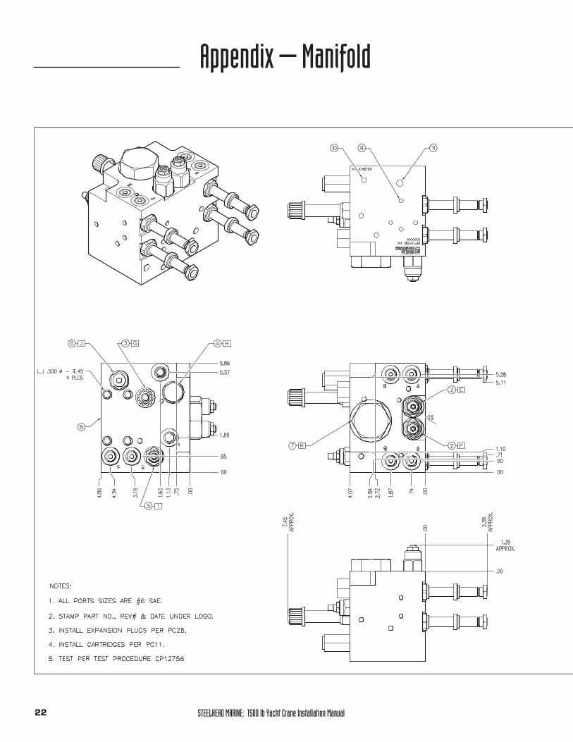
Appendix – Manifold
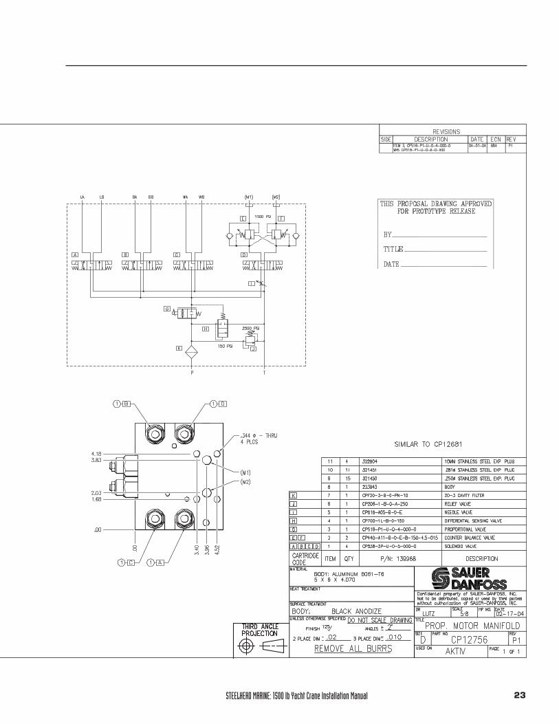
STEELHEAD MARINE: 1500 lb Yacht Crane Installation Manual 23
STEELHEAD MARINE: 1500 lb Yacht Crane Installation Manual24
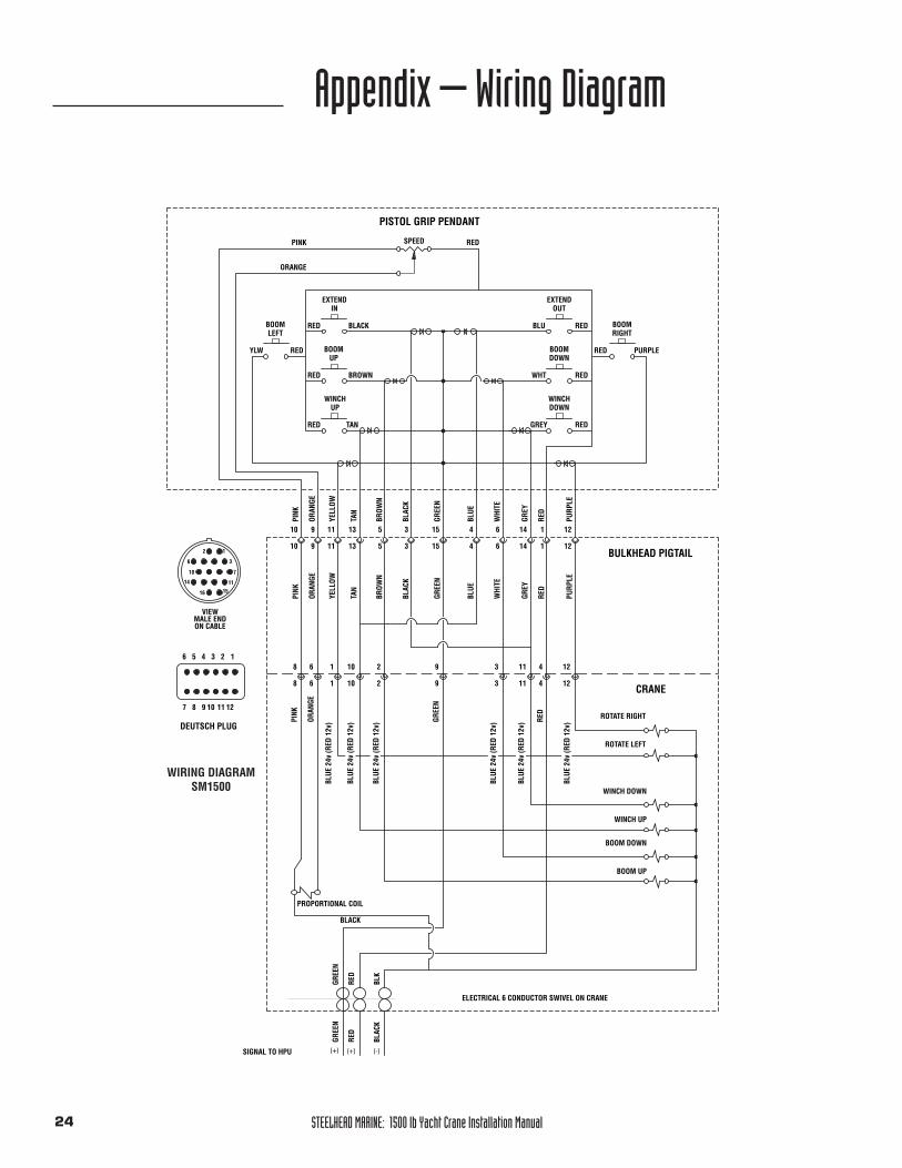
Appendix – Wiring Diagram
EXTEND EXTEND
BOOMBOOM
WINCH WINCH
BOOMBOOM
PURP
LE
RED
GREY
WHI
TE
BLUE
BLAC
K
BROW
N
TAN
YELL
OW
ORAN
GE
PINK
BLACK BLU
WHT
GREY
BROWN
TAN
PURPLEYLW
RED
RED
RED
RED RED
RED
RED
RED
BLAC
K
RED
PISTOL GRIP PENDANT
BULKHEAD PIGTAIL
ELECTRICAL 6 CONDUCTOR SWIVEL ON CRANE
RED
BLK
GREE
NGR
EEN
GREE
N
YELL
OW
PINK
ORAN
GE
TAN
BROW
N
WHI
TE
BLAC
K
GREE
N
BLUE
GREY
RED
PURP
LE
REDPINK
ORANGE
ORAN
GE
PINK
GREE
N
RED
CRANE
BLACK
VIEW MALE ENDON CABLE
1
3
7
1115
14
10
6
2
16
4
415
15
3
35
513
1311
119
9
10
10
6
6
14
14
1
1
12
12
2
2
8
8
6
6
10
10
1
1 9
9 3
3
411
11 4
12
12
ROTATE RIGHT
ROTATE LEFT
WINCH UP
WINCH DOWN
BOOM DOWN
BOOM UP
SIGNAL TO HPU (+) (+) (-)
6 5 4 3 2 1
121110987
PROPORTIONAL COIL
DEUTSCH PLUG
BLUE
24v
(RED
12v
)
BLUE
24v
(RED
12v
)
BLUE
24v
(RED
12v
)
BLUE
24v
(RED
12v
)
BLUE
24v
(RED
12v
)
BLUE
24v
(RED
12v
)LEFT
IN
UP
UP
DOWN
DOWN
OUT
RIGHT
SPEED
WIRING DIAGRAMSM1500


Steelhead Marine Ltd.7057 Beatty Drive
Mission, British ColumbiaCanada V2V 6C4
Tel: 604.826.1668Fax: 604.826.9992
E-mail: [email protected]
©2000 Steelhead Marine LtdREV J 1006 Printed in Canada
STEELHEADMARINE