Embed Size (px)
Citation preview

1
VTS Versatile Track System®
OWNER’S MANUAL
Rev. 030109
LOEGERING MFG. INC. 800-373-5441 15514 37
th Street SE 701-347-5441
Casselton, ND 58012 USA Fax: 701-347-4323 E-Mail: [email protected] Internet: www.loegering.com
2
Foreword
This manual contains safety, operation, maintenance, and adjustment information. The
procedures are designed to provide the best performance of the machine in an effective
and economical way. In order to obtain it, remember the next basic rules.
• This manual should be stored in the operator’s compartment of any
machine where this attachment is used.
• Before inspection, maintenance, or operating the VTS, read and
understand this manual completely.
• Since all of the explanations in this manual may not be thoroughly
understood at first, repeat reading it until abilities as an operator are
obtained and developed for proper operation.
• Further abilities as an operator outside of descriptions in this manual can
be obtained from experience during normal operations and under proper
supervision.
• Because of continuing improvement and advancement of product design,
the shape of the attachment in the illustrations may be partly different
from your machine. Whenever a question arises regarding your machine,
or this publication, please consult your local Loegering dealer or
Loegering Mfg. at 701-347-5441 for the latest information.

3
CONTENTS
-Serial Number Location Page 4
-Safety information: Page 5
Section 1-1 General Safety Page 6
Section 1-2 Safe Operation Page 7
Section 1-3 Safe Maintenance Page 7
Section 1-4 Safety Symbols Page 8
-Nomenclature: Page 9
-Installation: Page 10
Section 2-1 Installing the VTS: Safety Page 10
Section 2-2 Installing the VTS: Preparations Page 11
Section 2-3 Installing Wheel Spacers Page 12-13
Section 2-4 Installing the VTS Page 14-15
Section 2-5 Inspection of the VTS before use Page 16
-Maintenance: Page 17
Section 3-1 When Required Maintenance Page 17-19
Section 3-2 Replacement Safety Page 20
Section 3-3 Replacing Hub and Torsion Tube Page 21
Section 3-4 Replacing the Down Stop Page 22
Section 3-5 Replacing Tension Arm Assy. Page 22-24
Section 3-6 Replacing the Rubber Track Page 24-28
-VTS Parts 50+ Page 29-30
-VTS Parts 50+ Drawings Page 30-32
-VTS Parts 65+ & 85+ Page 33-34
-VTS Parts 65+ & 85+ Drawings Page 34-38
-VTS Torque Specifications Page 39
-MSDS Information Page 40-44
-VTS Warranty Information Page 45-48

4
Always provide the serial number of your VTS when ordering parts, requesting
service, requesting warranty, or any other information.
The serial number plate is located on top of the tunnel near the rear hub. Please
record the serial number in the space provided and on the warranty registration card.
Serial Numbers: Right VTS________ Left VTS ________
Serial Number Location
15514 37th St SE
Casselton, ND 58012
800-373-5441
www.loegering.com
Model #: LSBxx-x
Serial #: 1x-xxxxxx-xxx
Date of Mfg: xx-xx (MM-YY)
Weight (lbs.): xxxx
Capacity: xxxxxxxxx
Patent: xxxxxxxxx
5
SAFETY INFORMATION
We offer you basic and important rules and precautions for safe operation.
Read, understand, and observe them before starting operation. This is the most essential
way to prevent accidents.
Wrong operation, inspection, or maintenance can cause personal injury or death.
Throughout this manual and on the VTS, precautions are provided with marks and
classified by the words “Danger”, “Warning”, and “Caution” according to their extent
of danger.
The classification is as follows:
DANGER: indicates an imminently hazardous situation which, if not
avoided, will cause death. WARNING: indicates a potentially hazardous situation which, if not
avoided could result in death or serious injury. CAUTION: indicates a potentially hazardous situation which, if not
avoided, could result in minor or moderate injury. It may also be used to alert
against possible damage to the machine and its components. We have made every effort for you to prevent accidents during operation, however, we
cannot be held responsible for predicting every kind of danger in all operating conditions.
It is the owner or user of the machine who is responsible for ALWAYS paying attention
to operate the machine; as well as reading and understanding this manual enough to
obtain the essential knowledge and skills fundamental to correct machine operation.
WARNING • BEFORE inspection, operation, or maintenance of the VTS, be sure to
read and understand this manual.
• Incorrect operation or maintenance of the machine can cause an accident
and serious injury or death.
• Keep this manual on hand during operation so that you can immediately
consult it when necessary. If it should be missing or damaged, contact
Loegering Mfg. for a replacement.
• There are various kinds of federal, state, and local regulations that effect
construction and industrial machinery. Since the regulations are subject to
change, and differ from one locale to another, it is impossible for us to
provide such information in this manual. It is the responsibility of the
owner or user to be familiar with the regulations.
• Specifications and materials of the VTS are subject to change without any
obligation on the part of the manufacturer.

6
SAFETY TIPS
This section explains tips which you will find throughout this manual and on the VTS Track
System. Periodically check labels and plates containing those tips for damage. If they are
damaged, clean or replace them. For replacement, contact Loegering.
OBSERVE THE BASICS FOR SAFE
AND EFFECTIVE OPERATION.
The operator’s knowledge, skills, and
experience are the most important to
utilize the machine and VTS. Therefore,
be sure to understand operation procedures
and to take necessary training.
OPERATOR SHOULD BE
QUALIFIED.
Only qualified operators should operate
the machine, and those operators should
only do so when physically and mentally
alert.
The operator should be familiar with the
hazards and necessary safety measures
unique to the operation of VTS.
READ AND UNDERSTAND THE
INSTRUCTIONS AND WARNINGS.
This manual, plates, and labels on the
machine contain necessary instructions
and warnings for safe operation. Read and
understand all safety instructions and
warnings, failure to do so can result in
injury or death. Loegering will be glad to
answer any questions. If the manual, plate,
or label is missing or damaged, contact
Loegering for a replacement.
Remember that the safety tips that we
provide cannot cover every kind of
danger that you may encounter during
operation.
WEAR PROPER WORKING
CLOTHES.
Wear working clothes that fit closely.
Avoid loose jackets, shirt sleeves, rings,
and other jewelry that may get caught in
moving parts of the VTS. Always wear
protective items such as hard hats, safety
glasses, and ear protection as required.
PERFORM “WALK-AROUND”
INSPECTION.
Walk around the machine to check for
any safety concerns before operation of
the machine.
PERFORM SYSTEM CHECK.
Use the VTS slowly at first to ensure
proper operation of all moving parts.
Slow operation allows the operator to
notice potential safety hazards before
they occur.
1 SAFETY
1-1 GENERAL

7
CONDUCT ALL MANEUVERS WITH
THE VTS CAREFULLY.
Avoid making sharp turns with the VTS
installed. Sharp turns or standing pivot turns
will reduce the usable life of your VTS
system.
CAREFULLY LOAD AND UNLOAD
THE MACHINE.
The VTS system can increase the width of
your machine. Always ensure that the trailer
is the correct size to prevent damage to
trailers and/or the VTS.
CAPACITIES
When using the VTS system the machine
will be able to push and lift larger loads;
however, Loegering Mfg. recommends you
do not exceed the manufacture’s push and
lift maximums.
The maximum machine weight for the large
VTS is 10,500 lbs (4,763 kg). Maximum for
the small VTS is 7,500 lbs (3402 kg).
PERFORM MAINTENANCE
CAREFULLY.
Maintenance work can be hazardous if not
done in a careful manner. All personnel
should realize the hazards and strictly follow
safe practices. Before performing any
maintenance or repair work, consult the
instruction manual.
BE CAREFUL AROUND MOVING
PARTS.
Stay clear of all rotating or moving parts
such as sprockets and rollers.
Do not allow any object to come near
moving parts. The object could be thrown
out of the undercarriage.
ALWAYS CLEAN THE VTS
Maintain the cleanliness of the machine and
VTS to ensure proper and safe operation.
Remove dirt, debris, and any tools used for
maintenance from the undercarriage system.
ALWAYS USE APPROPRIATE
SAFETY EQUIPMENT.
Wear personal safety equipment when
necessary and use mechanical lifting devices
to aid in the service and maintenance of the
VTS.
1 SAFETY
1-2 OPERATION
1-3 MAINTENANCE

8
There are several specific safety signs on your VTS. Their exact location and description of the
hazard are reviewed in this section.
Please take the time to familiarize yourself with these safety signs.
1-4 Warning Signs and Labels
1 SAFETY
Safety decal indicates:
WARNING: Crush
Hazard, To prevent serious
injury from moving parts:
Consult owner’s manual or
service manual before
installing this equipment.
Keep hands and feet away
from moving suspension
parts.
Safety decal indicates:
WARNING: To avoid
severe injury.
- Never reach arms or legs
into a moving track. Stop
engine, lower implements to
the ground, place all controls
in neutral, set park brake,
remove ignition key and wait
for all moving parts to stop
before servicing, adjusting,
repairing or unplugging.
Safety decal indicates:
CAUTION:
- Read and understand the
operator’s manual before
using this equipment
- Stop engine, place all
controls in neutral, set park
brake, and remove ignition
key before servicing,
repairing, adjusting, or
unplugging.
- Keep hands and away
from moving parts.
-Make certain everyone is
clear before operating the
machine. Keep children,
visitors, and untrained
people away.
Safety decal indicates:
WARNING: To prevent
serious injury from flying
objects.
- Clear the area of
bystanders before
operating this equipment.
- Keep away from machine
while it is running, keep
others away.
- Shut down the machine if
anyone enters within 50
meters of this machine.
9
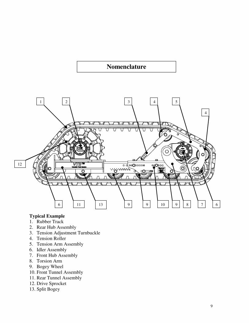
Typical Example
1. Rubber Track
2. Rear Hub Assembly
3. Tension Adjustment Turnbuckle
4. Tension Roller
5. Tension Arm Assembly
6. Idler Assembly
7. Front Hub Assembly
8. Torsion Arm
9. Bogey Wheel
10. Front Tunnel Assembly
11. Rear Tunnel Assembly
12. Drive Sprocket
13. Split Bogey
Nomenclature
1 2 3 4 5
4
6 8 10 9 9 13
11 6 7 9
12
10
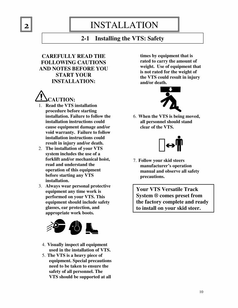
CAREFULLY READ THE
FOLLOWING CAUTIONS
AND NOTES BEFORE YOU
START YOUR
INSTALLATION:
CAUTION: 1. Read the VTS installation
procedure before starting
installation. Failure to follow the
installation instructions could
cause equipment damage and/or
void warranty. Failure to follow
installation instructions could
result in injury and/or death.
2. The installation of your VTS
system includes the use of a
forklift and/or mechanical hoist,
read and understand the
operation of this equipment
before starting any VTS
installation.
3. Always wear personal protective
equipment any time work is
performed on your VTS. This
equipment should include safety
glasses, ear protection, and
appropriate work boots.
4. Visually inspect all equipment
used in the installation of VTS.
5. The VTS is a heavy piece of
equipment. Special precautions
need to be taken to ensure the
safety of all personnel. The
VTS should be supported at all
times by equipment that is
rated to carry the amount of
weight. Use of equipment that
is not rated for the weight of
the VTS could result in injury
and/or death.
6. When the VTS is being moved,
all personnel should stand
clear of the VTS.
7. Follow your skid steers
manufacturer’s operation
manual and observe all safety
precautions.
INSTALLATION 2
2-1 Installing the VTS: Safety
3-1
Your VTS Versatile Track
System ® comes preset from
the factory complete and ready
to install on your skid steer.
11
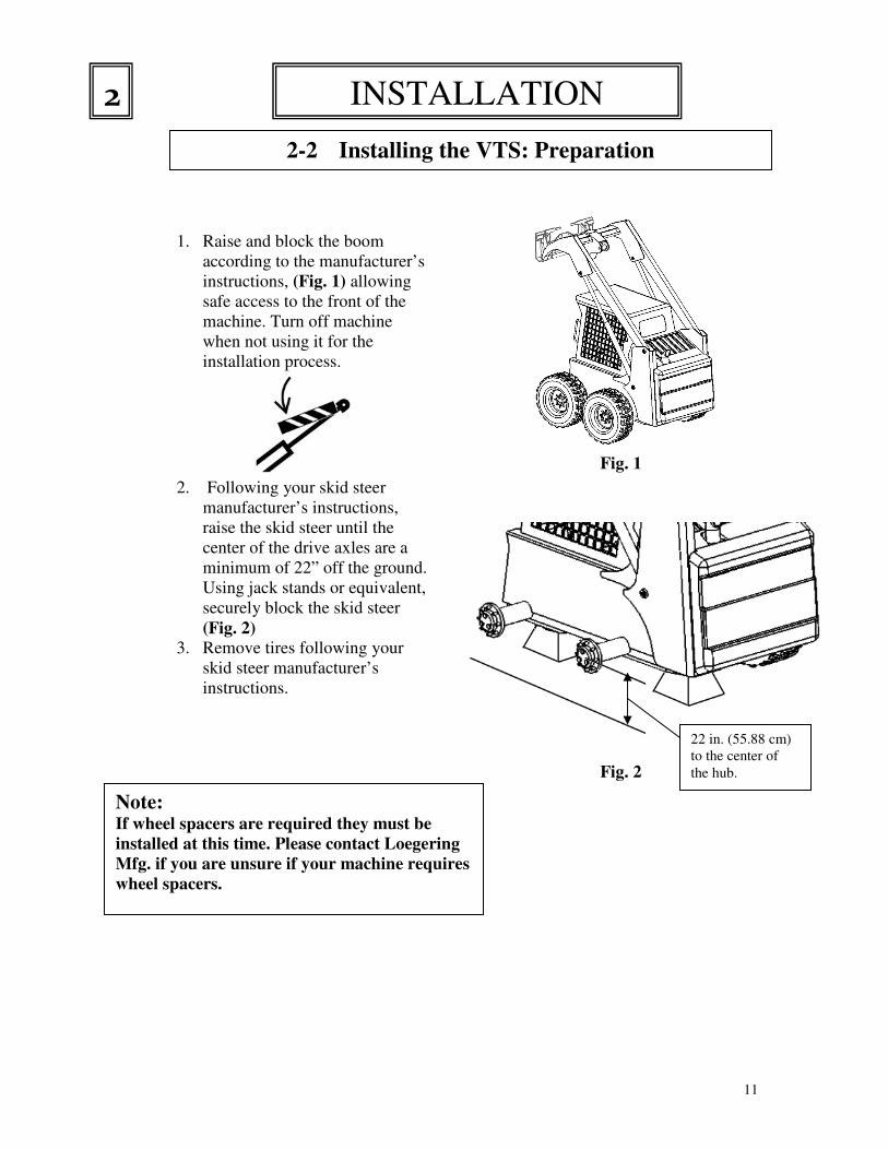
1. Raise and block the boom
according to the manufacturer’s
instructions, (Fig. 1) allowing
safe access to the front of the
machine. Turn off machine
when not using it for the
installation process.
2. Following your skid steer
manufacturer’s instructions,
raise the skid steer until the
center of the drive axles are a
minimum of 22” off the ground.
Using jack stands or equivalent,
securely block the skid steer
(Fig. 2) 3. Remove tires following your
skid steer manufacturer’s
instructions.
Fig. 1
Fig. 2
INSTALLATION 2
2-2 Installing the VTS: Preparation
3-2
22 in. (55.88 cm)
to the center of
the hub.
Note: If wheel spacers are required they must be
installed at this time. Please contact Loegering
Mfg. if you are unsure if your machine requires
wheel spacers.
12
Safety Precautions:
1. Always wear appropriate eye,
ear, hand, and foot protection
while installing wheel
spacers.
2. Ensure that the machine is
secure on the jack stands
before starting install of
wheel spacers.
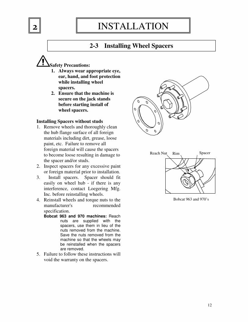
Installing Spacers without studs
1. Remove wheels and thoroughly clean
the hub flange surface of all foreign
materials including dirt, grease, loose
paint, etc. Failure to remove all
foreign material will cause the spacers
to become loose resulting in damage to
the spacer and/or studs.
2. Inspect spacers for any excessive paint
or foreign material prior to installation.
3. Install spacers. Spacer should fit
easily on wheel hub - if there is any
interference, contact Loegering Mfg.
Inc. before reinstalling wheels.
4. Reinstall wheels and torque nuts to the
manufacturer's recommended
specification. Bobcat 963 and 970 machines: Reach
nuts are supplied with the spacers, use them in lieu of the nuts removed from the machine. Save the nuts removed from the machine so that the wheels may be reinstalled when the spacers are removed.
5. Failure to follow these instructions will
void the warranty on the spacers.
2-3 Installing Wheel Spacers
3-3
INSTALLATION 2
Spacer Rim Reach Nut
Bobcat 963 and 970’s
13
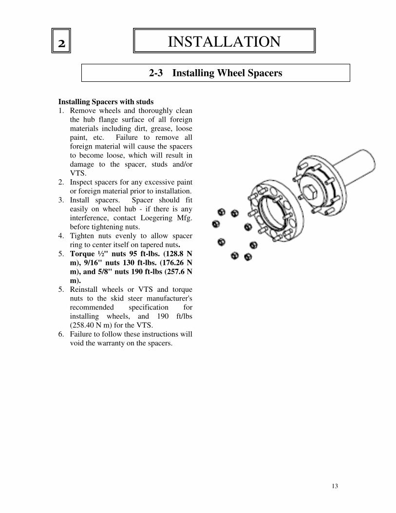
Installing Spacers with studs
1. Remove wheels and thoroughly clean
the hub flange surface of all foreign
materials including dirt, grease, loose
paint, etc. Failure to remove all
foreign material will cause the spacers
to become loose, which will result in
damage to the spacer, studs and/or
VTS.
2. Inspect spacers for any excessive paint
or foreign material prior to installation.
3. Install spacers. Spacer should fit
easily on wheel hub - if there is any
interference, contact Loegering Mfg.
before tightening nuts.
4. Tighten nuts evenly to allow spacer
ring to center itself on tapered nuts.
5. Torque ½" nuts 95 ft-lbs. (128.8 N
m), 9/16" nuts 130 ft-lbs. (176.26 N
m), and 5/8" nuts 190 ft-lbs (257.6 N
m).
5. Reinstall wheels or VTS and torque
nuts to the skid steer manufacturer's
recommended specification for
installing wheels, and 190 ft/lbs
(258.40 N m) for the VTS.
6. Failure to follow these instructions will
void the warranty on the spacers.
2-3 Installing Wheel Spacers
3-4
INSTALLATION 2

14
1. Using a forklift or similar lifting
device, lift the VTS at one of three
places.
a. Below the track.
b. Below the tunnel, between the
bogey wheels. (Preferred)
c. Below the top of track
IMPORTANT: Make sure the front of
the skid steer’s hubs and the front
of the mating hubs on the VTS are
clean. Excessive dirt, mud, gravel
etc., will interfere with the
installation. 2. Start by installing the VTS onto the
front hub of the skid steer.
3. Align the front hub assembly. The
front hub assembly will pivot
forward approximately 3-4”.
Rotate the hub assembly forward
and block it, turn the hub spindle
until the spindle holes align with
the studs on the skid steer hub.
Caution: While rotating the
front hub ensure that hands and
fingers remain clear of any pinch
points.
4. You may have to take the block out
and lower and / or raise the hub
assembly slightly in order to line up
the spindle holes with the studs on the
skid steer.
5. When the holes on the front spindle
line up with the studs, slide the VTS
onto the front hub.
Caution: Be sure that all
personnel are clear of the area before
moving the VTS onto the machine.
Failure to do so could result in injury
and/or death from being crushed in
between the VTS and the machine.
6. Install as many wheel nuts as possible
on the front hub assembly (3-4
typically) and tighten. Note: If your
machine is equipped with flange
type wheel nuts you must replace
them with 90° tapered wheel nuts.
Failure to use 90° tapered wheel
nuts may cause injury, damage to
the lug studs, and/or void warranty.
7. When using a fork lift, use the side
shift capabilities to slide the VTS
towards the rear of the skid steer until
the rear sprocket lines up with the rear
hub. Note: A hoist can also
accomplish this step.
8. Have an operator start the skid steer
and rotate the hub until the studs line
up with the VTS. Caution: Stay
clear of the VTS while the skid
steer is in operation.
9. When the holes on the rear sprocket
line up with the studs, slide the VTS
onto the rear hub.
2-4 Installing the VTS
3-5
INSTALLATION 2
15
Caution: Be sure that all
personnel are clear of the area before
moving the VTS onto the machine.
Failure to do so could result in injury
and/or death from being crushed in
between the VTS and the machine.
10. Install as many wheel nuts as
possible, typically 3 or 4.
11. Have an operator start the skid
steer and slowly rotate the hubs
forward until all the wheel nuts can
be installed.
12. Turn machine off in between
rotations to install additional wheel
nuts.
Note: Torque all wheel nuts to 190 ft/lbs (257.6 N m). Failure
to properly torque wheel nuts
can cause injury, damage to
equipment and void the
warranty.
13. Repeat the installation procedure for
the other side.
14. Once both sides have been installed,
follow the instructions in section 3
and check the tension on the track.
Ensure that the tension is between 1”
and 1.5” (2.54 to 3.81 cm).
15. Remove jack stands or blocks and
lower the machine.
16. Check both sides for proper
installation before using the machine.
IMPORTANT
Before putting the skid steer with VTS
into use, take the machine for a test
drive, bring it back in and check the
tension again. Also check the torque on
the wheel nuts to ensure that all torques
are correct.
2-5 Installing the VTS
3-6
INSTALLATION 2

16
INSPECT YOUR VTS BEFORE EACH OPERATING
SESSION
1. Check the rubber track for signs of
wear. Check for any cracks, cuts,
missing pieces, or excessive wear.
(Fig. 1 & 2)
2. Ensure that all bolts are tight and
that none are missing.
3. Check for any damage to the metal
components of the undercarriage.
Look for cracks, abnormal wear, or
bent components.
4. Visually inspect all tension rollers,
bogey wheels, and idlers for signs
of damage or excessive amounts of
wear. (Fig. 3)
5. Inspect the sprocket for missing
teeth, cracks, or excessive wear.
Fig. 1
Fig. 2
Fig. 3
2-6 Inspecting your VTS before each use.
3-7
INSTALLATION 2
17
Tracks check and adjust
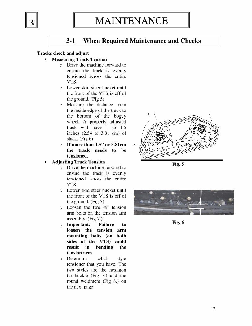
• Measuring Track Tension o Drive the machine forward to
ensure the track is evenly
tensioned across the entire
VTS.
o Lower skid steer bucket until
the front of the VTS is off of
the ground. (Fig 5)
o Measure the distance from
the inside edge of the track to
the bottom of the bogey
wheel. A properly adjusted
track will have 1 to 1.5
inches (2.54 to 3.81 cm) of
slack. (Fig 6)
o If more than 1.5” or 3.81cm
the track needs to be
tensioned.
• Adjusting Track Tension o Drive the machine forward to
ensure the track is evenly
tensioned across the entire
VTS.
o Lower skid steer bucket until
the front of the VTS is off of
the ground. (Fig 5)
o Loosen the two ¾” tension
arm bolts on the tension arm
assembly. (Fig 7.)
o Important: Failure to
loosen the tension arm
mounting bolts (on both
sides of the VTS) could
result in bending the
tension arm.
o Determine what style
tensioner that you have. The
two styles are the hexagon
turnbuckle (Fig 7.) and the
round weldment (Fig 8.) on
the next page
Fig. 5
Fig. 6
3 MAINTENANCE
3-1 When Required Maintenance and Checks
18
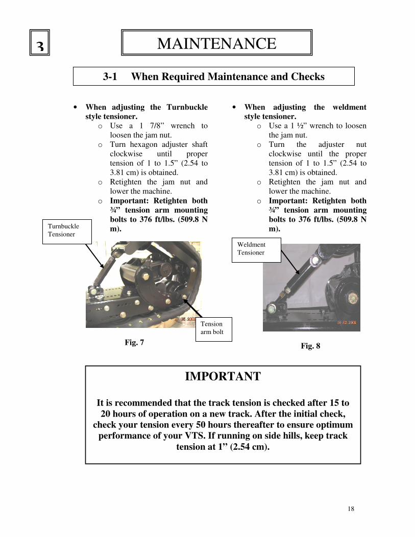
• When adjusting the Turnbuckle
style tensioner.
o Use a 1 7/8” wrench to
loosen the jam nut.
o Turn hexagon adjuster shaft
clockwise until proper
tension of 1 to 1.5” (2.54 to
3.81 cm) is obtained.
o Retighten the jam nut and
lower the machine.
o Important: Retighten both
¾” tension arm mounting
bolts to 376 ft/lbs. (509.8 N
m).
Fig. 7
• When adjusting the weldment
style tensioner. o Use a 1 ½” wrench to loosen
the jam nut.
o Turn the adjuster nut
clockwise until the proper
tension of 1 to 1.5” (2.54 to
3.81 cm) is obtained.
o Retighten the jam nut and
lower the machine.
o Important: Retighten both
¾” tension arm mounting
bolts to 376 ft/lbs. (509.8 N
m).
Fig. 8
Turnbuckle
Tensioner
Tension
arm bolt
Weldment
Tensioner
MAINTENANCE 3
3-1 When Required Maintenance and Checks
IMPORTANT
It is recommended that the track tension is checked after 15 to
20 hours of operation on a new track. After the initial check,
check your tension every 50 hours thereafter to ensure optimum
performance of your VTS. If running on side hills, keep track
tension at 1” (2.54 cm).
19
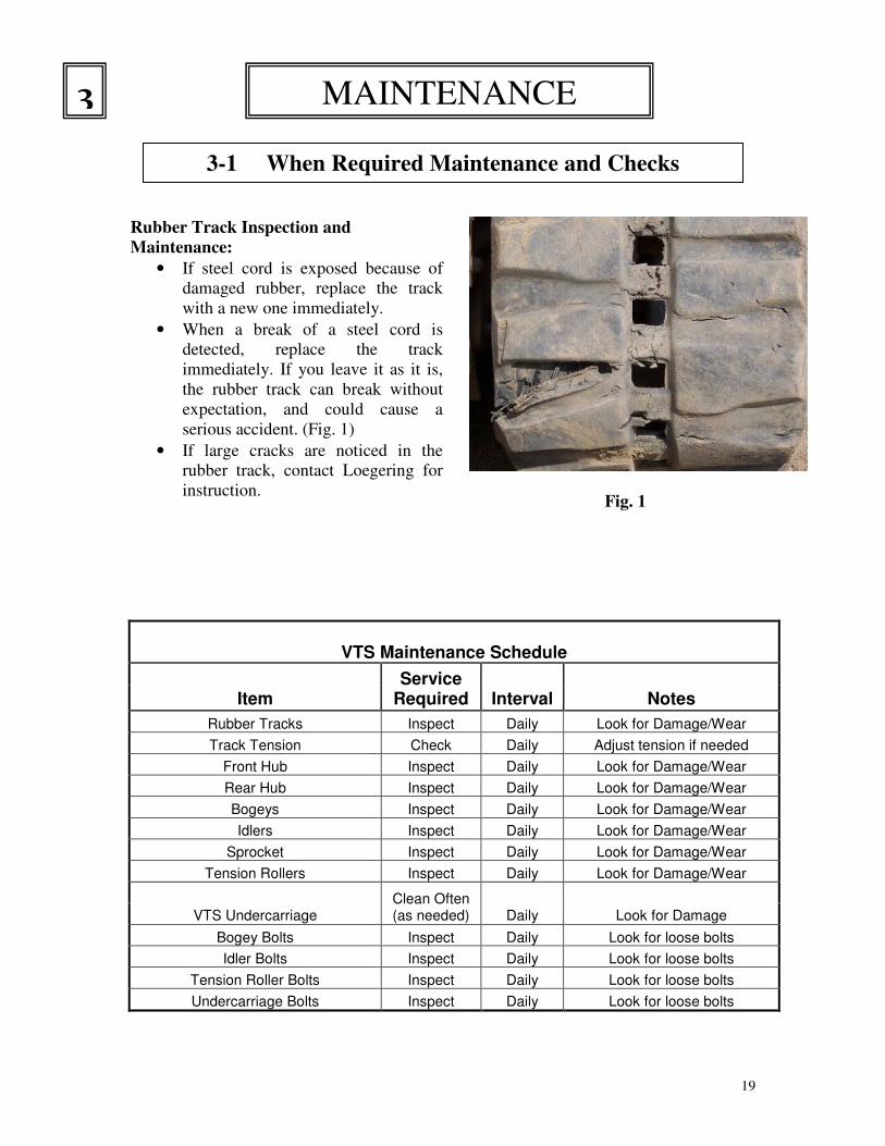
Rubber Track Inspection and
Maintenance:
• If steel cord is exposed because of
damaged rubber, replace the track
with a new one immediately.
• When a break of a steel cord is
detected, replace the track
immediately. If you leave it as it is,
the rubber track can break without
expectation, and could cause a
serious accident. (Fig. 1)
• If large cracks are noticed in the
rubber track, contact Loegering for
instruction.
Fig. 1
VTS Maintenance Schedule
Item Service
Required Interval Notes
Rubber Tracks Inspect Daily Look for Damage/Wear
Track Tension Check Daily Adjust tension if needed
Front Hub Inspect Daily Look for Damage/Wear
Rear Hub Inspect Daily Look for Damage/Wear
Bogeys Inspect Daily Look for Damage/Wear
Idlers Inspect Daily Look for Damage/Wear
Sprocket Inspect Daily Look for Damage/Wear
Tension Rollers Inspect Daily Look for Damage/Wear
VTS Undercarriage Clean Often (as needed) Daily Look for Damage
Bogey Bolts Inspect Daily Look for loose bolts
Idler Bolts Inspect Daily Look for loose bolts
Tension Roller Bolts Inspect Daily Look for loose bolts
Undercarriage Bolts Inspect Daily Look for loose bolts
MAINTENANCE 3
3-1 When Required Maintenance and Checks
20
Caution:
1. The torsion tube and hub
assembly can only be
removed after the VTS has
been removed from the
machine.
2. Follow the installation and
removal instructions to
complete VTS removal.
3. Read and understand all
instruction for torsion
tube and hub removal
before starting the
removal.
4. The assembly is a heavy
object and needs to be
removed using a hoist.
Read and understand all
manuals for the hoist that
is to be used before
starting removal process.
5. Always use a hoist when
handling the assembly.
6. Wear all personal safety
equipment while
completing any service on
the VTS. Safety glasses,
ear protection, and proper
work boots are required.
7. The assembly creates a
pinch point, use caution
and keep hands and
fingers clear of the pinch
point when removing the
assembly.
3-2 Replacing the Hub or Torsion Tube; Safety.
3-3
MAINTENANCE 3

21
Note: VTS must be removed from
machine before attempting to remove
hub and torsion tube. Consult
installing the VTS section for
removal instructions.
1. Remove torsion arm.
a. Locate torsion arm
without “up stop” arm.
Note: All VTS, except
VTS for Bobcats, will
have the torsion arm
without the up stop arm
toward the outside of the
skid steer.
b. Using a 1 ½ socket
remove the 1-14UNC x
2” bolt on the upper part
of the torsion arm. Fig. 1
Note: This bolt is torqued
at the factory to 750
ft/lbs. (1017 N m)
c. Using a 1-1/8”socket
remove the ¾ x 2” bolt
from the lower torsion
arm on the opposite side.
2. Remove front hub assembly
a. Carefully lift the front
hub assembly out of the
frame.
3. Remove hub assembly. Fig 1
Fig. 1
a. Using a ¾”socket and
wrench remove the four
½ x 1.5” bolts and nuts
that secure the hub to
torsion tube
4. Install new hub assembly in the
same position as the old hub.
Fig. 1
a. Position hub on torsion
tube and secure using ½ x
1.5” bolt and nuts.
Torque to 110 ft/lb.
(149.14 N m) b. Reinstall assembly onto
the VTS.
5. Install VTS on skid steer per
owners manual.
6. Adjust track tension per owners
manual
MAINTENANCE 3
3-3 Replacing the Hub or Torsion Tube
Torsion tube.
Note: As of February 2007 the down stop
assembly has been moved from the hub to the
tunnel on 65+ & 86+ VTS. The rubber stop,
part # 400540, will still be available for older
hubs for a limited time however it is highly
advised to switch to the new down stop for
better performance. In addition, new
replacement hub assemblies will no longer
have holes for down stop assemblies and
require the purchase of down stop assembly
part # 600544. Please see next page for
instruction.
22
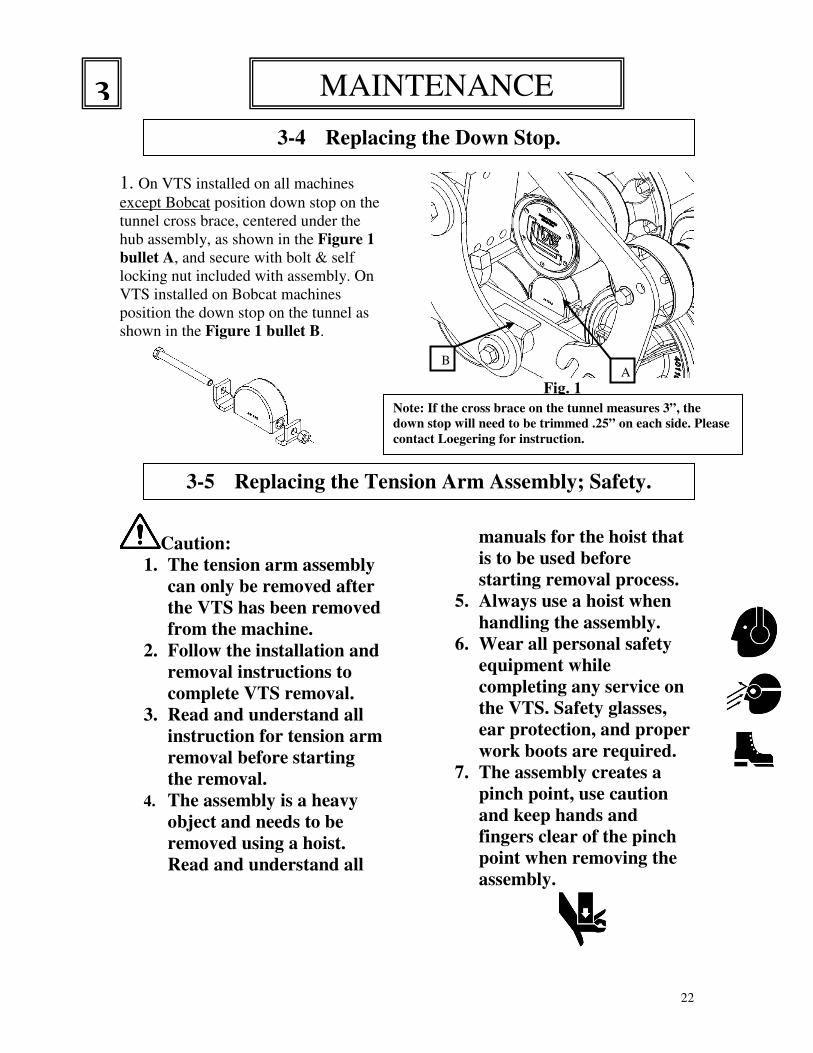
1. On VTS installed on all machines
except Bobcat position down stop on the
tunnel cross brace, centered under the
hub assembly, as shown in the Figure 1
bullet A, and secure with bolt & self
locking nut included with assembly. On
VTS installed on Bobcat machines
position the down stop on the tunnel as
shown in the Figure 1 bullet B.
Caution:
1. The tension arm assembly
can only be removed after
the VTS has been removed
from the machine.
2. Follow the installation and
removal instructions to
complete VTS removal.
3. Read and understand all
instruction for tension arm
removal before starting
the removal.
4. The assembly is a heavy
object and needs to be
removed using a hoist.
Read and understand all
Fig. 1
manuals for the hoist that
is to be used before
starting removal process.
5. Always use a hoist when
handling the assembly.
6. Wear all personal safety
equipment while
completing any service on
the VTS. Safety glasses,
ear protection, and proper
work boots are required.
7. The assembly creates a
pinch point, use caution
and keep hands and
fingers clear of the pinch
point when removing the
assembly.
3-5 Replacing the Tension Arm Assembly; Safety.
3-6
MAINTENANCE 3
3-4 Replacing the Down Stop.
3-5
A B
Note: If the cross brace on the tunnel measures 3”, the
down stop will need to be trimmed .25” on each side. Please
contact Loegering for instruction.
23
1. Follow torsion arm and hub
assembly removal instructions to
VTS must be removed from
machine, consult owners manual
for removal instructions.
2. Before starting, note location of
rollers and position of tension
arm slot. Replace one side at a
time using one side as a reference
when reassembling.
3. Remove the torsion arm and hub
assembly. 4. Remove tension roller assembly.
(Fig.1 on previous page.)
a. Using a 1-1/8” x ½ drive
socket loosen the two
3/4” bolts securing the
tension arm assembly to
the frame, do not remove
these bolts.
b. Loosen the tension
adjustment screw until it
can be lifted out of the
frame. Use a hoist to lift
the front half of the track
to provide clearance for
the tension arm assembly
to be removed.
5. Lift the tension roller assembly
up and out.
6. Replacing tension rollers.
a. Note position of rollers
before removing. If
reconfiguring VTS or
moving rollers to another
position contact
Loegering for a drawing
for correct position.
b. Install roller assembly
using two ¾ x 1½ gr. 8
flange bolts and torque to
376 ft/lbs (509.8 N m).
7. Tension arm assembly
installation. Ref. Fig. 3
a. Using a hoist, lift the
front half of track to
provide clearance for the
tension arm assembly.
b. Position the correct slot
on the tension arm
assembly over the bolts
loosened in step 4.
Do not tighten bolts at this
time; tighten bolts after
track has been properly
tensioned. c. Position the adjuster
screw into holder on front
chassis. Note: If you can
not get the adjuster screw
into the holder it may be
necessary to use a bottle
jack or similar lifting
device, to lift the tension
arm assembly. Center the
jack under the adjusting
screw mounting brace or
center under the upper
tension roller (a cradle is
required for this).
8. Install front hub assembly.
a. Extend adjuster fully to
allow clearance for the
hub assembly.
b. Slide assembly into the
frame.
3-5 Replacing the Tension Arm Assembly
3-7
MAINTENANCE 3

24
(Step 8 continued)
c. Position torsion arm on
assembly and secure
using 1-14UNC x 2” Gr.
8 bolt on the upper arm
and a 3/4 -10UNC x 2”
Gr. 8 bolt on the lower.
Torque upper bolt to
750 ft/lbs. (1017 N m)
and lower bolt to 376
ft/lbs (509.8 N m).
DANGER: Please read all
caution statements and
notes before proceeding.
When elevated on the forks the
VTS may work itself forward
and could come off the forks.
Frequently check to ensure the
VTS is securely positioned on
the forks.
1. Replacing the track on your
VTS system includes the
use of a forklift and/or
mechanical hoist, read and
understand the operation of
this equipment before
starting any VTS track
replacement.
2. Always wear personal
protective equipment any
time work is performed on
your VTS. This equipment
should include safety
glasses, ear protection, and
appropriate work boots.
3. Visually inspect all
equipment used in the track
replacement.
4. The VTS is a heavy piece of
equipment. Special
precautions need to be
taken to ensure the safety of
all personnel. The VTS
should be supported at all
times by equipment that is
rated to carry the amount
of weight. Use of
equipment that is not rated
for the weight of the VTS
could result in injury
and/or death.
MAINTENANCE 3
3-5 Replacing the Tension Arm Assembly
3-8
3-6 Replacing the Rubber Track; Safety
3-9
Note: After the VTS has been
reassembled and all bolts have
been properly torqued, it can be
reinstalled on the machine by
following the instructions in
section 2-2
25
5. When the VTS is being
moved, all personnel should
stand clear of the VTS.
6. Follow your skid steers
manufacturer’s operation
manual and observe all
safety precautions.
7. When lifting components of
the VTS that weigh over 30
lbs. (13.6 kg) it may be
necessary to use an
approved hoist.
1. Use a forklift or similar device to
pickup the VTS. For ease of
taking off the old track and
putting on the new track pick the
VTS up from the inside (skid
steer side) under the tunnel with
the forks sticking out
approximately 6 inches on the
opposite side. Lift the VTS off
the ground approximately 32
inches.
2. Replace one side at a time using
the other side as a reference.
3. To assist in the installation of a
new track the following items
will assist in making the job
easier and less time consuming:
Forklift, scissor lift, 1 ½ x ¾
drive socket, 1 1/8 x ½ drive
sockets, pump jack and hoist.
4. Follow instructions in section 3-3
to remove the torsion arm and
hub assembly.
5. Follow instructions in section 3-5
to remove the tension arm
assembly.
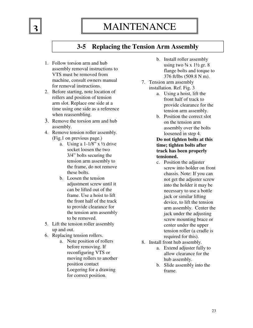
6. Remove the Track
Make sure the bottom of the
track is up against the bottom of
the bogeys to allow the slack to
go to the front of the VTS.
a. With a pry bar move the
rear sprocket clockwise
this will move the slack
in the track to the front of
the VTS. (Fig. 1)
Fig. 1
THE VTS MUST BE REMOVED
FROM THE SKID STEER
BEFORE YOU CAN PROCEED
WITH THE TRACK
REPLACEMENT
3-6 Replacing the Rubber Track
3-10
Place pry bar between
idler and track
MAINTENANCE 3

26
7. Lower the front of the track so it
elongates. Place a pry bar
between the front idler and the
inside of the track and pry
outwards so the idler pops out of
the guide teeth. (Fig. 2)
8. Move to the rear of the VTS and
place your hoist strap or chain in
front of the sprocket, lift up the
track with the hoist. (Fig. 3)
9. Using a pry bar, pry the track
upwards until the sprocket is out
of the Track Idler Guides.
10. Once the track is off the sprocket
place a pry bar between the rear
idler and the inside of the track
and pry outward so the idler
comes out of the Track
Idler Guides. (Fig. 3)
Fig. 2
Fig. 3
MAINTENANCE 3
Lower the hoist to
relieve the track
tension so the track
elongates.
3-6 Replacing the Rubber Track
3-11
Lift the top of the
track in this area
Place pry bar in this area.

27
Installing the new track
1. Pickup the new track with a hoist
or similar device. Start at the rear
of the VTS.
a. Guide the rear idler into the
Track Idler Guides. Fig. 4
b. Use a scissors lift or similar
device to lift up the bottom
of the track until the track
touches the bottom bogies.
This elongates the track in
order to get it over the
sprocket and front idler.
Fig. 4 c. Lift the top of the track in
front of the sprocket with a
hoist or similar device. Fig.
4 d. With a pry bar between the
top of the sprocket and the
track lift up on the track
until the sprocket is in the
Track Idler Guide. Fig. 4
e. With a pry bar move the
rear sprocket clockwise,
this will move more slack
to the front of the VTS.
Fig. 4. Lower the hoist to
relieve the tension on the
track.
f. With a pry bar between
the front idler and the
track, pry outward until
the front idler goes into
the Track Idler Guides.
Fig. 5
Fig. 4
Fig. 5
2. Reinstall your tension arm
assembly.
3. Reinstall the torsion arm and hub
assembly.
4. Ensure that all bolts are torqued
according to the torque diagram
included with this manual.
5. Reinstall VTS on the machine
using instructions in section 2-2.
A B
C
D
E
F
3-6 Replacing the Rubber Track
3-12
MAINTENANCE 3
28
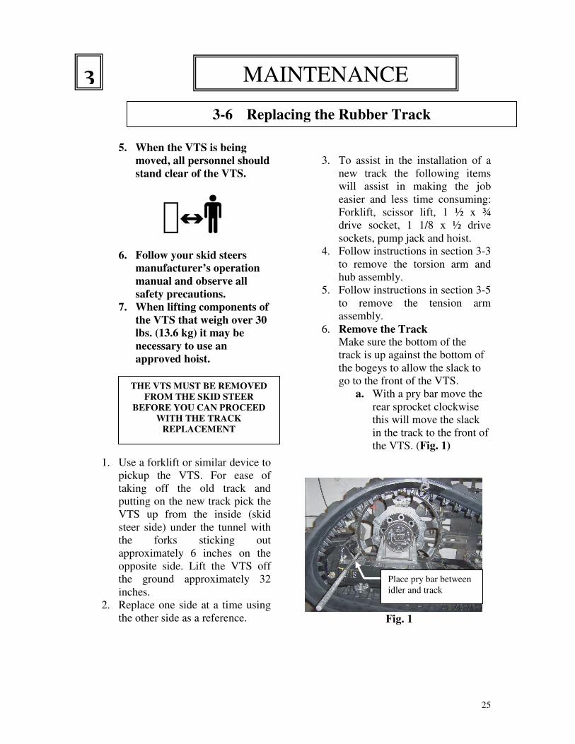
Replacing the rubber track by placing
the undercarriage into the track.
1. Start with the track setting on the
floor with the upper portion
suspended by a hoist.
2. Use a forklift or similar lifting
device to move the undercarriage
into the track.
a. Lift the top of the track
above the sprocket with a
hoist or similar lifting
device. (Fig. 1)
b. Approach the track at an
angle so the rear idler can
be placed in the track
idler guide. (Fig. 1)
c. With a pry bar between
the top of the sprocket
and the track lift up on
the track until the
sprocket is in the Track
Idler Guide.
d. Lower the track onto the
sprocket. (Fig. 2.)
e. With a pry bar, rotate the
sprocket towards the front
of the VTS to move the
slack to the front.
f. Lock the sprocket with
the pry bar. (Fig. 3)
Fig. 1
Fig. 2
Fig. 3
3-6 Replacing the Rubber Track
3-13
MAINTENANCE 3

29
g. Use a pry bar to move the
track so the front idler is in
the track idler guide. (Fig. 4)
3. Reinstall your tension arm assembly.
(Fig. 5)
4. Reinstall the torsion arm and hub
assembly. (Fig. 6)
5. Reinstall VTS on the machine using
instructions in section 2-2.
Fig. 4
Fig. 5
Fig. 6
3-7 Replacing the Rubber Track
3-14
MAINTENANCE 3
After the new track is installed, 1. Ensure that all bolts are torqued according to the torque diagram included with this manual.
2. Ensure that all lug nuts are torqued to specification.
3. Check the track tension after the VTS is installed on the machine.
4. Check the track tension again after 15 to 20 hours of initial use.
5. Routinely check track tension at 50 hour intervals throughout the life of the track.

30
VTS Part Prices
50+
Fig. Item Part Number Description Wt. 401363 Track, Rubber, 50 Link, 12" Wide (Qty.1) 462
401767 Track, Rubber, 51 Link, 12" Wide (Qty.1) 470
401362 Track, Rubber, 52 Link, 12" Wide (Qty.1) 479
401361 Track, Rubber, 54 Link, 12" Wide (Qty.1) 497
1 1
401360 Track, Rubber, 56 Link, 12" Wide (Qty.1) 509
401364 Track, Rubber, 50 Link, 15" Wide (Qty.1) 479
401347 Track, Rubber, 52 Link, 15" Wide (Qty.1) 491
401346 Track, Rubber, 54 Link, 15" Wide (Qty.1) 507 1 2
401345 Track, Rubber, 56 Link, 15" Wide (Qty.1) 524
1,4 3 600456 Turnbuckle Assembly 8
1 4 600907 Hub / Sprocket Assembly
4 5 600906 Hub / Sprocket Assembly (no offset sprocket)
500329 Right Rear Tunnel (Shown) 1,4 6
500325 Left Rear Tunnel
1,4 7 601553 Tension Arm Assembly
1 600942 Front Right Hub Torsion Assembly (All except Bobcat)
1 600913 Front Left Hub Torsion Assembly (All except Bobcat)
4,5 600941 Front Right Hub Torsion Assembly (Bobcat only)
4,5
8
600912 Front Left Hub Torsion Assembly (Bobcat only)
1,4 9 500326 Front Tunnel
1 10 601700
Tunnel Support Bracket (Only available on long wheelbase Compact VTS. Call for info)
2 11 400914 Sprocket Offset 52
5 12 401449 Sprocket No Offset 50
2,5 13 601058 Rear Hub 78
2,5 14 401075-8 Screw, Socket Head, 5/8-11 x 1.25", Gr. 8 Pltd. (Qty. 8) 2
2,3 15 PD5210-1.5CP Bolt, Flange, 3/4"-10UNC x 1.50", Grade 8 Plated 0.2
2,3,5 16 PD5210-2CP Bolt, 3/4"-10UNC x 2.00", Grade 8 Plated 0.2
2,3 17 401425 Dust cover for 600716 1
2,3 18 600716 Idler, Assembly, dust cover not included 61
2 19 601350 Bogey, Split Solid Casting 30
2 20 401405 Dust cover for 601350 1
2,3 21 600549 Bogey Assembly, dust cover not included 30
2,3 22 401330 Dust cover for 600549 1
2 23 401391 Dust cover for 600741 1
2 24 600741 Tension Roller Assembly, dust cover not included 25
2 25 500515 Tension Arm (requires 2 bushings Item 26) 37
2 26 402169 Tension Arm Bushing 0.2
2,5 27 PD5170-1.5CP Bolt, Flange, 1/2"-13UNC x 1.50", Grade 8 Plated 0.1
2,5 28 500327 Torsion Tube, 11.18" Long 25
2,5 29 500302 Torsion Arm with upstop block, Right 11
2,5 30 400665 Bolt, 1"-14UNC x 2.00", Grade 8 Plated 1
2,5 31 500303 Torsion Arm, Left 10
2,5 32 600540 Hub, Front, Right, Assembly 40
2,5 33 PH5170-4CP Nut, Flange, Lock, 1/2"-13 Grade 8 Plated 0.1
2,5 34 401300 Shaft, Suspension, 11.18" Long 9
2,5 35 PH0190-5CP Nut, 5/8"-11NC Grade 8 Jam Nut 0.1
2,5 36 PD0190-3CP Bolt, 5/8"-11NC x 3.0", Grade 8 0.3
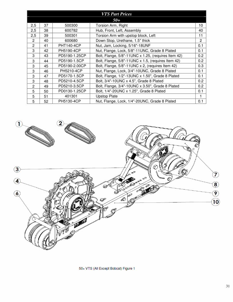
31
VTS Part Prices
50+ 2,5 37 500300 Torsion Arm, Right 10
2,5 38 600782 Hub, Front, Left, Assembly 40
2,5 39 500301 Torsion Arm with upstop block, Left 11
2 40 600680 Down Stop, Urethane, 1.5" thick 2
2 41 PHT140-4CP Nut, Jam, Locking, 5/16"-18UNF 0.1
3 42 PH5190-4CP Nut, Flange, Lock, 5/8"-11UNC, Grade 8 Plated 0.1
3 43 PD5190-1.25CP Bolt, Flange, 5/8"-11UNC x 1.25, (requires Item 42) 0.2
3 44 PD5190-1.5CP Bolt, Flange, 5/8"-11UNC x 1.5, (requires Item 42) 0.2
3 45 PD5190-2.00CP Bolt, Flange, 5/8"-11UNC x 2, (requires Item 42) 0.3
3 46 PH5210-4CP Nut, Flange, Lock, 3/4"-10UNC, Grade 8 Plated 0.1
3 47 PD5170-1.5CP Bolt, Flange, 1/2"-13UNC x 1.50", Grade 8 Plated 0.1
3 48 PD5210-4.5CP Bolt, 3/4"-10UNC x 4.5", Grade 8 Plated 0.2
2 49 PD5210-3.5CP Bolt, Flange, 3/4"-10UNC x 3.50", Grade 8 Plated 0.2
5 50 PD0130-1.25CP Bolt, 1/4"-20UNC x 1.25", Grade 8 Plated 0.1
5 51 401301 Upstop Plate 1
5 52 PH5130-4CP Nut, Flange, Lock, 1/4"-20UNC, Grade 8 Plated 0.1

32

33

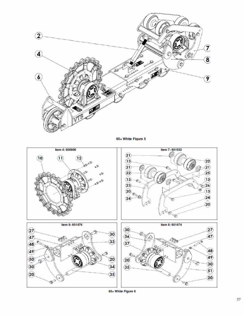
34
VTS Part Prices
65+ & 86+
Item Fig. Part # DESCRIPTION Wt.#
400285 Track, Rubber, 56 Link, 18" Wide (Qty.1) 542
401338 Track, Rubber, 58 Link, 18" Wide (Qty.1) 560
401087 Track, Rubber, 59 Link, 18" Wide (Qty.1) 575
400527 Track, Rubber, 60 Link, 18" Wide (Qty.1) 580
1 1
401348 Track, Rubber, 63 Link, 18" Wide (Qty.1) 600
600546 Turnbuckle Assy. 8 2 1,4,5
601209 Turnbuckle Assy. Extended Length 8
3 1 600504 Rear Hub Sprocket Assembly 172
4 4 600906 Rear Hub Sprocket Assembly (No Offset) 172
500175 Right Rear Tunnel (Shown) 5 1,3
500176 Left Rear Tunnel
500519 Right Rear Tunnel No Offset (Shown) 6 1,7
500349 Left Rear Tunnel No Offset
7 1,5 601552 Tension Arm Assembly
600514 Front Right Hub Torsion Assembly (Shown) 1,2
600516 Front Left Hub Torsion Assembly
601476 Front Right Hub Torsion Assembly Bobcat (Shown) 8
5,7 601474 Front Left Hub Torsion Assembly Bobcat
500294 Right Front Tunnel (Shown) 9
1,3,5, 7 500293 Left Front Tunnel
2 400914 Sprocket, 22 Tooth 89 10
6 401449 Sprocket, 22 tooth no offset
11 2,6 600461 Assembly, Rear Hub, (sprocket sold separately) 79.5
12 2,6 401075-8 Screw, Cap, 5/8-11UNC x 1.25" Gr. Plated 2.0
13 2-7 PD5210-1.5CP Bolt, Flange, 3/4" -10UNC x 1.5", Gr. 8 Plated 0.2
14 2,6 401111 Dust Cover for 600439 (2 required) 0.5
15 3,7 600439 Assembly, Idler Guide (Dust covers not included) 56
16 3,7 600458 Bogey, Split (Dust cover not included) 17
17 3,7 401405 Dust Cover for 600458 (1 required) 1
18 3,7 600457 Assembly, Bogey (Dust covers not included) 61.0
19 3,7 401118 Dust Cover for 600457 (2 required) 0.5
20 2-7 PD5210-2CP Bolt, Flange, 3/4" -10UNC x 2.0", Gr. 8 Plated 0.2
21 2,6 401118 Dust Cover for 600456 (2 required) 0.5
22 2,6 600456 Assembly, Roller, Tension 38
23 2,6 500514 Arm, Tension (requires 2 bushings, 402169 Item 24) 34
24 2,6 402169 Bushing 1" OD x .781" ID
25 2,6 PD5210-3.5CP Bolt, Flange, 3/4"-10UNC x 3.5", Gr. 8 Plated 0.2
26 2,6 PH5210-4CP Nut, Flange, Lock 3/4"-10UNC, Gr. 8 Plated 0.2
27 2,6 PD5190-1.25CP
Bolt, Flange, 5/8" -11UNC x 1.25" Gr. 8 Plated 0.2
2,6 500057 Torsion Tube 42 28
4 500486 Heavy Duty Torsion Tube (63 link VTS) 42
500203 Torsion Arm, Right w/ Stop 13 29 2
601403 Kit, Adjustable Torsion Arm (Includes Items 29, 31, 32) 13
30 2,6 400665 Bolt, 1-14UNC x 2.00" Gr. 8 Plated 1
31 2 PH0190-5CP Nut 5/8-11UNC Gr. 8 Jam Nut
32 2 PD0190-3CP Bolt 5/8-11NCx3.0 Gr. 8 Plated Fl Thrd
33 2,6 500055 Torsion Arm 12
600459 Hub, Front, Right 66 34 2,6
601263 Kit, Front Right hub and downstop kit 69

35
VTS Part Prices
65+ & 86+
Item Fig. Part # DESCRIPTION Wt.#
35 2,6 400297 Shaft, Suspension 9
36 2,6 500054 Torsion Arm, 12
600460 Hub, Front, Left 66 37 2,6
601262 Kit, Front Left hub and downstop kit 69
500204 Torsion Arm, Left w/ Stop 13 38 2
601402 Kit, Adjustable Torsion Arm (Includes Items 38, 31, 32) 13
39 3,7 600544 Down Stop Assy. (1 ea.) 3.0
40 3,7 PD5190-1.5CP Bolt, Flange, 5/8" -11UNC x 1.5" Gr. 8 Plated 0.2
41 3,7 PD5210-4.5CP Flange Bolt 3/4-10NCx4.5 Gr. 8 1.0
42 3,7 PH5190-4CP Nut, Flange, Lock 5/8"-11UNC, Gr. 8 Plated 0.2
43 4 600716 Rear Idler for 63 link VTS 61.0
44 4 401425 Dust Cover for 600716 0.5
500431 Right Rear Tunnel 63 Link 45 4
500429 Left Rear Tunnel 63 Link
500283 Right Front Tunnel 63 Link 46 4
500284 Left Front Tunnel 63 Link
47 6 500516 Torsion Tube Bobcat
48 6 PD0190-4.5CP Bolt 5/8-11NCx4.5 Gr. 8 Plated
49 6 PH0190-1CP Nut 1"-11UNC Gr. 8 Jam Nut
50 6 500518 Torsion arm Right for Bobcat
51 6 500517 Torsion arm Left for Bobcat

36
37

38

39
Item Description Torque(US) Torque(Metric) Socket
1 1-14UNC x 2” Gr. 8 750 ft/lbs. 1017 N m 1½ “
2 5/8-11UNC x 1½” Gr. 8 211 ft/lbs. 286.1 N m 1-5/16”
3 3/4 -10UNC x 1½ Gr. 8 376 ft/lbs. 509.8 N m 1-1/8”
4 3/4 -10UNC x 2” Gr. 8 376 ft/lbs. 509.8 N m 1-1/8”
5 3/4 -10UNC x 3½ Gr. 8 376 ft/lbs. 509.8 N m 1-1/8”
6 5/8 Sprocket Cap screws 211 ft/lbs. 286.1 N m
VTS Torque Specification Chart
1
3
2
2
3
4
5
6
2
40
41

42
43
44

45

46
Warranty Registration Form Please complete and return to Loegering to validate warranty.
Purchase Date: Form Completion Date:
Order #:
Dealer Name:
Contact Name:
Address:
City: State: Zip:
Phone Number:
Fax Number: Email Address:
User Name:
Contact Name:
Address:
City: State: Zip:
Phone Number:
Fax Number: Email Address:
Part Number Description Serial Number Model
Was there evidence of damage upon receipt? Yes No
If yes, explain:
Tell us about the equipment you plan to use your new attachment on.
Manufacturer: Model: Tire Size (tracks only):
* Hours of use on machine prior to installation of attachment: _______________Hours.
* Hour information is very important to warranty resolution. Warranty may not be valid
without completion of this section.
Application description:
Loegering15514 37th Street SECasselton, ND 58012 USAPh: 800-373-5441Fax: 701-347-4323

47


![Administering Cisco VTS · admin@VTS-A:~$ sudo su [sudo] password for admin: Step2 SourcetheVTSenvironment. root@VTS-A:# source /etc/profile.d/ncs.sh Step3 VerifyVTSstatus. root@VTS-A:#](https://img.pdfslide.us/doc/110x75/5ec8e3d704a90406890d6ec6/administering-cisco-vts-adminvts-a-sudo-su-sudo-password-for-admin-step2.jpg)