Embed Size (px)
Citation preview
1
Location identification (id)
Classification Northing Easting Land-surface elevation Agency database Aquifer completed Well status Dedicated pump
Location layer
Location id
Classification Installation dateWell typeMeasuring point elevation Total well depth Remarks
Well construction
Location id
AgencyDate measuredStatic depthSounding Measure methodCompanyRemarks
Water levels
Location id
AgencyLogging dateLithology topLithology bottomStratigraphic unit Logging companyVisual description
Lithology
Location id
Depth top screenDepth bottom screenScreen diameterScreen slot sizePercent open Screen material
Screened interval(s)
Trichloroethene Dichloroethene
Location idAgencyContaminantDate measuredMatrixConcentration UnitDetection limitData source
Location idAgencyContaminantDate measuredMatrixConcentration UnitDetection limitData source
Location idAgencyContaminantDate measuredMatrixConcentration UnitDetection limitData source
Location idAgencyContaminantDate measuredMatrixConcentration UnitDetection limitData source
Vinyl chloride Tetrachloroethene
Volatile organic compounds
Location idAgencyContaminantDate measuredMatrixConcentration UnitDetection limitData source
Benzene
Location idAgencyContaminantDate measuredMatrixConcentration UnitDetection limitData source
Toluene
Location idAgencyContaminantDate measuredMatrixConcentration UnitDetection limitData source
Ethylbenzene
Location idAgencyContaminantDate measuredMatrixConcentration UnitDetection limitData source
Xylene
Location data
Well-construction,lithology, water-leveldata
Water-quality data
EXPLANATION
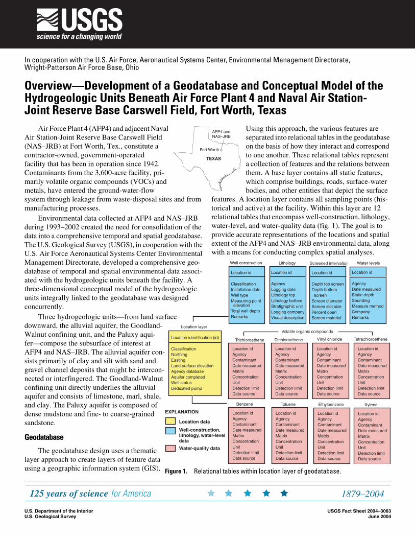
Figure 1. Relational tables within location layer of geodatabase.
Fort Worth
AFP4 and NAS–JRB
TEXAS
Air Force Plant 4 (AFP4) and adjacent Naval Air Station-Joint Reserve Base Carswell Field (NAS–JRB) at Fort Worth, Tex., constitute a contractor-owned, government-operated facility that has been in operation since 1942. Contaminants from the 3,600-acre facility, pri-marily volatile organic compounds (VOCs) and metals, have entered the ground-water-flow system through leakage from waste-disposal sites and from manufacturing processes.
Environmental data collected at AFP4 and NAS–JRB during 1993–2002 created the need for consolidation of the data into a comprehensive temporal and spatial geodatabase. The U.S. Geological Survey (USGS), in cooperation with the U.S. Air Force Aeronautical Systems Center Environmental Management Directorate, developed a comprehensive geo-database of temporal and spatial environmental data associ-ated with the hydrogeologic units beneath the facility. A three-dimensional conceptual model of the hydrogeologic units integrally linked to the geodatabase was designed concurrently.
Three hydrogeologic units—from land surface downward, the alluvial aquifer, the Goodland-Walnut confining unit, and the Paluxy aqui-fer—compose the subsurface of interest at AFP4 and NAS–JRB. The alluvial aquifer con-sists primarily of clay and silt with sand and gravel channel deposits that might be intercon-nected or interfingered. The Goodland-Walnut confining unit directly underlies the alluvial aquifer and consists of limestone, marl, shale, and clay. The Paluxy aquifer is composed of dense mudstone and fine- to coarse-grained sandstone.
Geodatabase
The geodatabase design uses a thematic layer approach to create layers of feature data using a geographic information system (GIS).
Using this approach, the various features are separated into relational tables in the geodatabase on the basis of how they interact and correspond to one another. These relational tables represent a collection of features and the relations between them. A base layer contains all static features, which comprise buildings, roads, surface-water bodies, and other entities that depict the surface
features. A location layer contains all sampling points (his-torical and active) at the facility. Within this layer are 12 relational tables that encompass well-construction, lithology, water-level, and water-quality data (fig. 1). The goal is to provide accurate representations of the locations and spatial extent of the AFP4 and NAS–JRB environmental data, along with a means for conducting complex spatial analyses.
Overview—Development of a Geodatabase and Conceptual Model of the Hydrogeologic Units Beneath Air Force Plant 4 and Naval Air Station-Joint Reserve Base Carswell Field, Fort Worth, Texas
In cooperation with the U.S. Air Force, Aeronautical Systems Center, Environmental Management Directorate, Wright-Patterson Air Force Base, Ohio
U.S. Department of the InteriorU.S. Geological Survey
USGS Fact Sheet 2004–3063June 2004
sachinFS.fm Page 1 Friday, June 18, 2004 11:08 AM
2
Alluvial aquifer
Goodland-Walnut confining unit
Paluxy aquifer
The geodatabase is accessed using a GIS that integrates the spatial framework of the geodatabase and manages the environmental data. The GIS provides information to users through interactive sessions with maps and symbols on a per-sonal computer. Thus, the geodatabase coupled with the GIS accepts queries for and retrieves specific geologic, hydro-logic, and water-quality information.
Conceptual Model
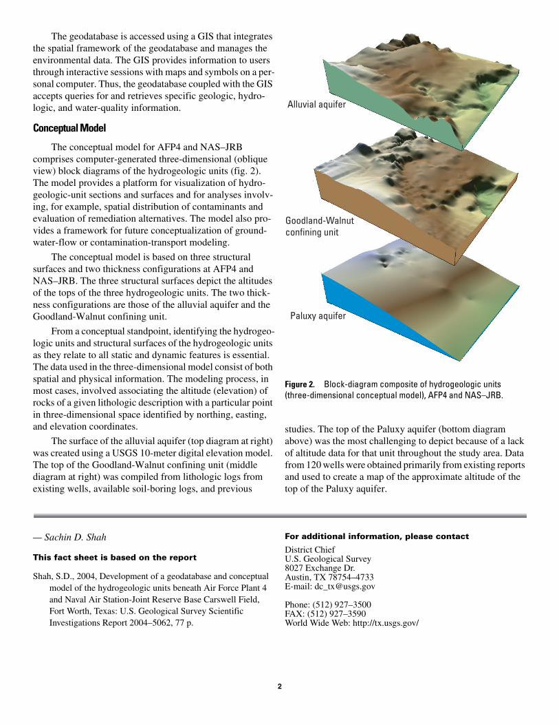
The conceptual model for AFP4 and NAS–JRB comprises computer-generated three-dimensional (oblique view) block diagrams of the hydrogeologic units (fig. 2). The model provides a platform for visualization of hydro-geologic-unit sections and surfaces and for analyses involv-ing, for example, spatial distribution of contaminants and evaluation of remediation alternatives. The model also pro-vides a framework for future conceptualization of ground-water-flow or contamination-transport modeling.
The conceptual model is based on three structural surfaces and two thickness configurations at AFP4 and NAS–JRB. The three structural surfaces depict the altitudes of the tops of the three hydrogeologic units. The two thick-ness configurations are those of the alluvial aquifer and the Goodland-Walnut confining unit.
From a conceptual standpoint, identifying the hydrogeo-logic units and structural surfaces of the hydrogeologic units as they relate to all static and dynamic features is essential. The data used in the three-dimensional model consist of both spatial and physical information. The modeling process, in most cases, involved associating the altitude (elevation) of rocks of a given lithologic description with a particular point in three-dimensional space identified by northing, easting, and elevation coordinates.
The surface of the alluvial aquifer (top diagram at right) was created using a USGS 10-meter digital elevation model. The top of the Goodland-Walnut confining unit (middle diagram at right) was compiled from lithologic logs from existing wells, available soil-boring logs, and previous
studies. The top of the Paluxy aquifer (bottom diagram above) was the most challenging to depict because of a lack of altitude data for that unit throughout the study area. Data from 120 wells were obtained primarily from existing reports and used to create a map of the approximate altitude of the top of the Paluxy aquifer.
— Sachin D. Shah
This fact sheet is based on the report
Shah, S.D., 2004, Development of a geodatabase and conceptual model of the hydrogeologic units beneath Air Force Plant 4 and Naval Air Station-Joint Reserve Base Carswell Field, Fort Worth, Texas: U.S. Geological Survey Scientific Investigations Report 2004–5062, 77 p.
For additional information, please contact
District ChiefU.S. Geological Survey8027 Exchange Dr. Austin, TX 78754–4733E-mail: [email protected]
Phone: (512) 927–3500FAX: (512) 927–3590World Wide Web: http://tx.usgs.gov/
Figure 2. Block-diagram composite of hydrogeologic units (three-dimensional conceptual model), AFP4 and NAS–JRB.