Embed Size (px)
Citation preview
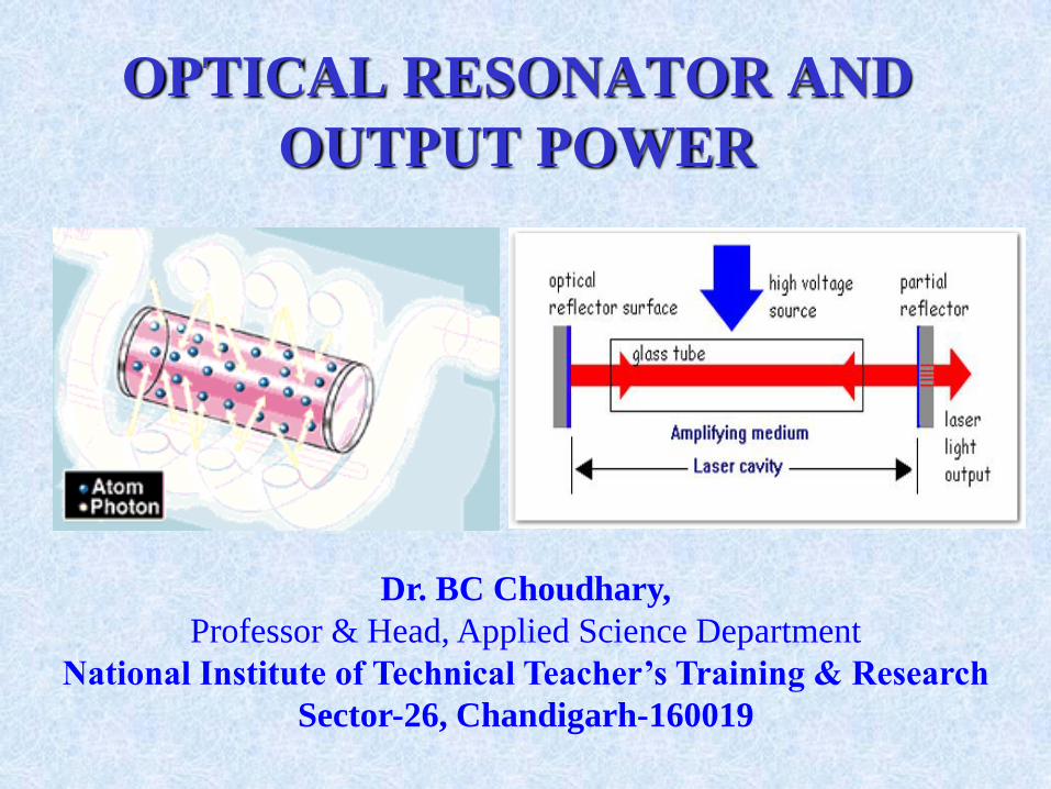
OPTICAL RESONATOR AND
OUTPUT POWER
Dr. BC Choudhary,
Professor & Head, Applied Science Department
National Institute of Technical Teacher’s Training & Research
Sector-26, Chandigarh-160019
Content Outlines
Laser as an Oscillator
Optical Resonator and Cavity modes
Gain Saturation and Output frequencies
Laser Rate Equations
Optimum Output Power
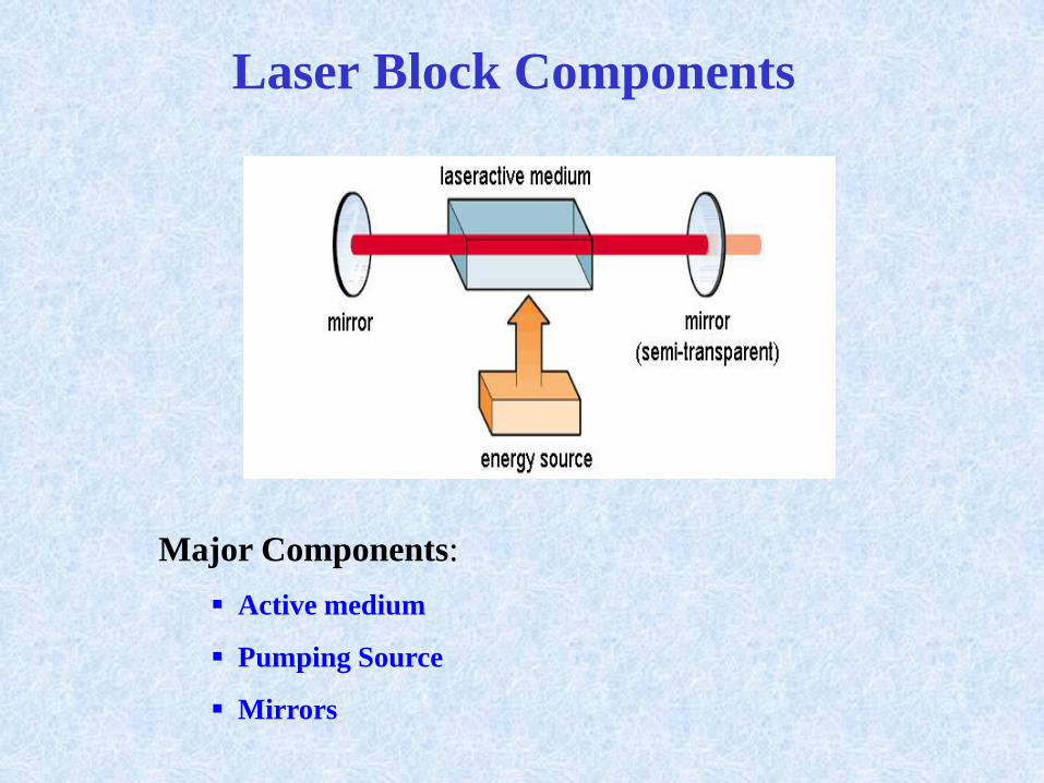
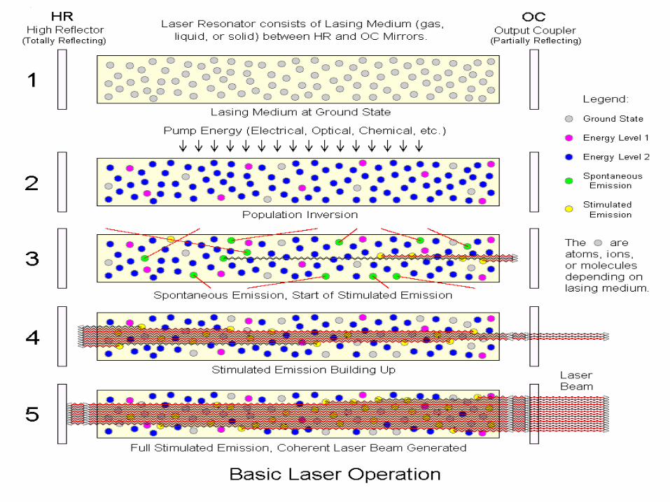
Laser Block Components
Major Components:
Active medium
Pumping Source
Mirrors
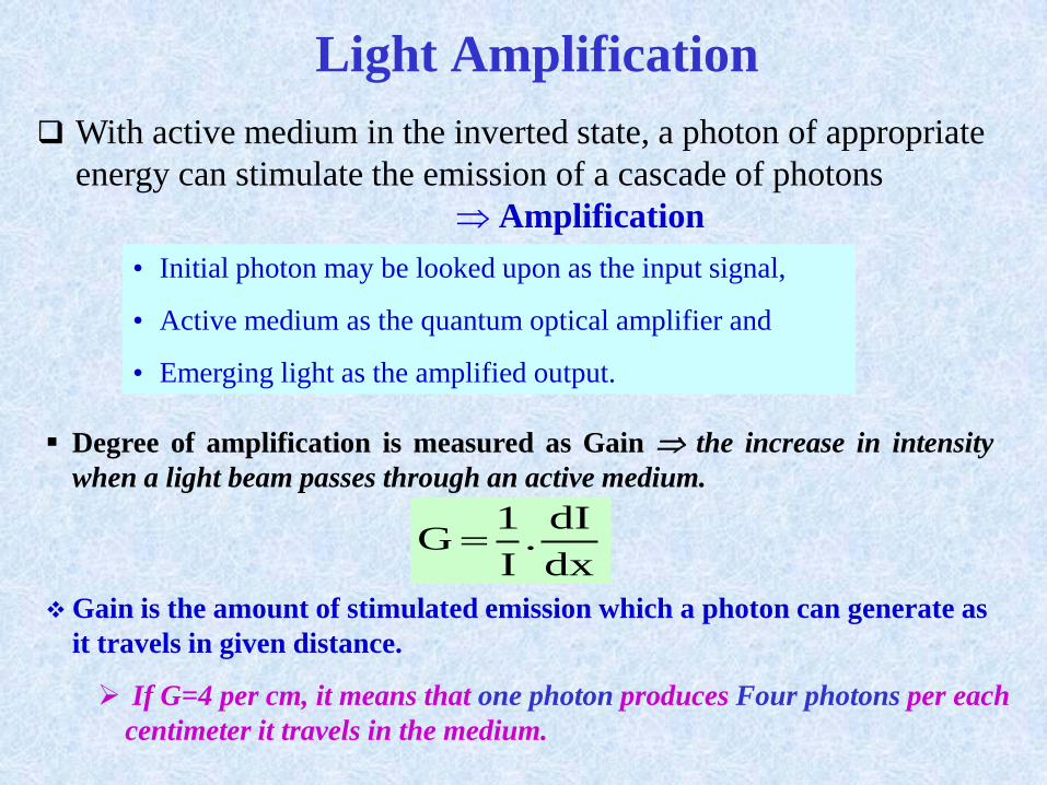
Light Amplification
With active medium in the inverted state, a photon of appropriate
energy can stimulate the emission of a cascade of photons
Amplification
• Initial photon may be looked upon as the input signal,
• Active medium as the quantum optical amplifier and
• Emerging light as the amplified output.
Degree of amplification is measured as Gain the increase in intensity
when a light beam passes through an active medium.
dx
dI.
I
1G
Gain is the amount of stimulated emission which a photon can generate as
it travels in given distance.
If G=4 per cm, it means that one photon produces Four photons per each
centimeter it travels in the medium.
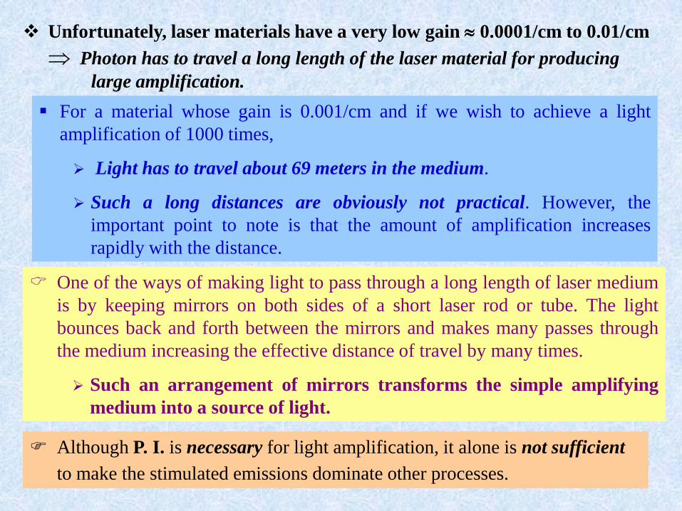
Unfortunately, laser materials have a very low gain 0.0001/cm to 0.01/cm
Photon has to travel a long length of the laser material for producing
large amplification.
For a material whose gain is 0.001/cm and if we wish to achieve a light
amplification of 1000 times,
Light has to travel about 69 meters in the medium.
Such a long distances are obviously not practical. However, the
important point to note is that the amount of amplification increases
rapidly with the distance.
One of the ways of making light to pass through a long length of laser medium
is by keeping mirrors on both sides of a short laser rod or tube. The light
bounces back and forth between the mirrors and makes many passes through
the medium increasing the effective distance of travel by many times.
Such an arrangement of mirrors transforms the simple amplifying
medium into a source of light.
Although P. I. is necessary for light amplification, it alone is not sufficient
to make the stimulated emissions dominate other processes.
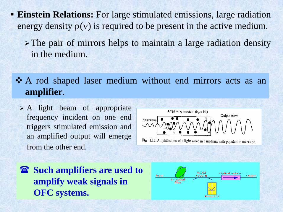
Einstein Relations: For large stimulated emissions, large radiation
energy density () is required to be present in the active medium.
The pair of mirrors helps to maintain a large radiation density
in the medium.
A rod shaped laser medium without end mirrors acts as an
amplifier.
A light beam of appropriate
frequency incident on one end
triggers stimulated emission and
an amplified output will emerge
from the other end.
Such amplifiers are used to
amplify weak signals in
OFC systems.
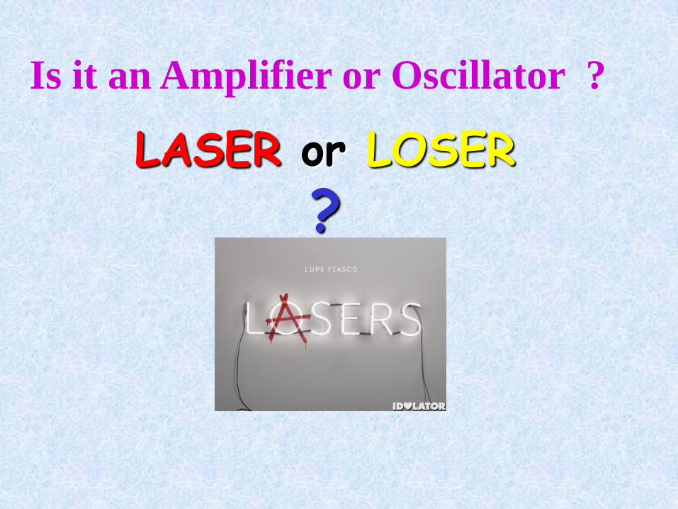
Is it an Amplifier or Oscillator ?
LASER or LOSER
?
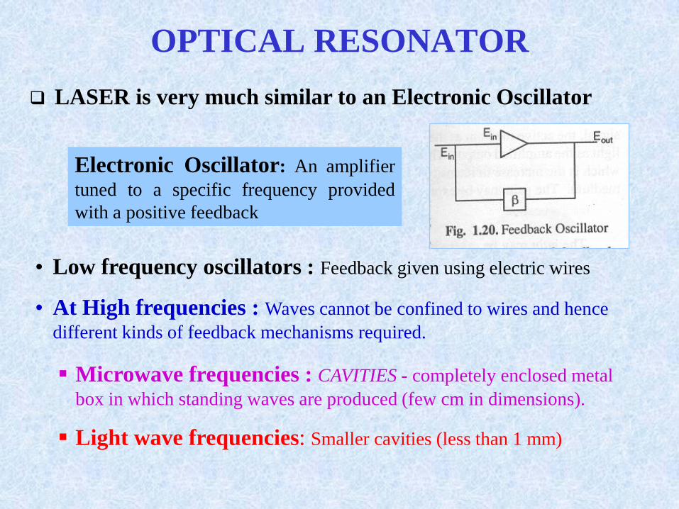
OPTICAL RESONATOR
LASER is very much similar to an Electronic Oscillator
Electronic Oscillator: An amplifier
tuned to a specific frequency provided
with a positive feedback
• Low frequency oscillators : Feedback given using electric wires
• At High frequencies : Waves cannot be confined to wires and hence
different kinds of feedback mechanisms required.
Microwave frequencies : CAVITIES - completely enclosed metal
box in which standing waves are produced (few cm in dimensions).
Light wave frequencies: Smaller cavities (less than 1 mm)
Townes & Schawlow NO NECESSITY FOR A CLOSED
CAVITY; AN OPEN CAVITY IN THE FORM OF TWO PARALLEL
MIRRORS WILL SERVE THE PURPOSE.
In Lasers
Feedback obtained by placing active medium between a pair of
mirrors facing each other.
Role of input signal played by chance photon spontaneously emitted
along optic axis of laser rod.
Amplification: Photons reflected back into active medium by the
mirrors several times, gaining strength at each passage.
NOT FEASIBLE TO FABRICATE CAVITIES FOR USE AT LIGHT
FREQUENCIES
Dimensions (order of wavelength) 0.5 mm
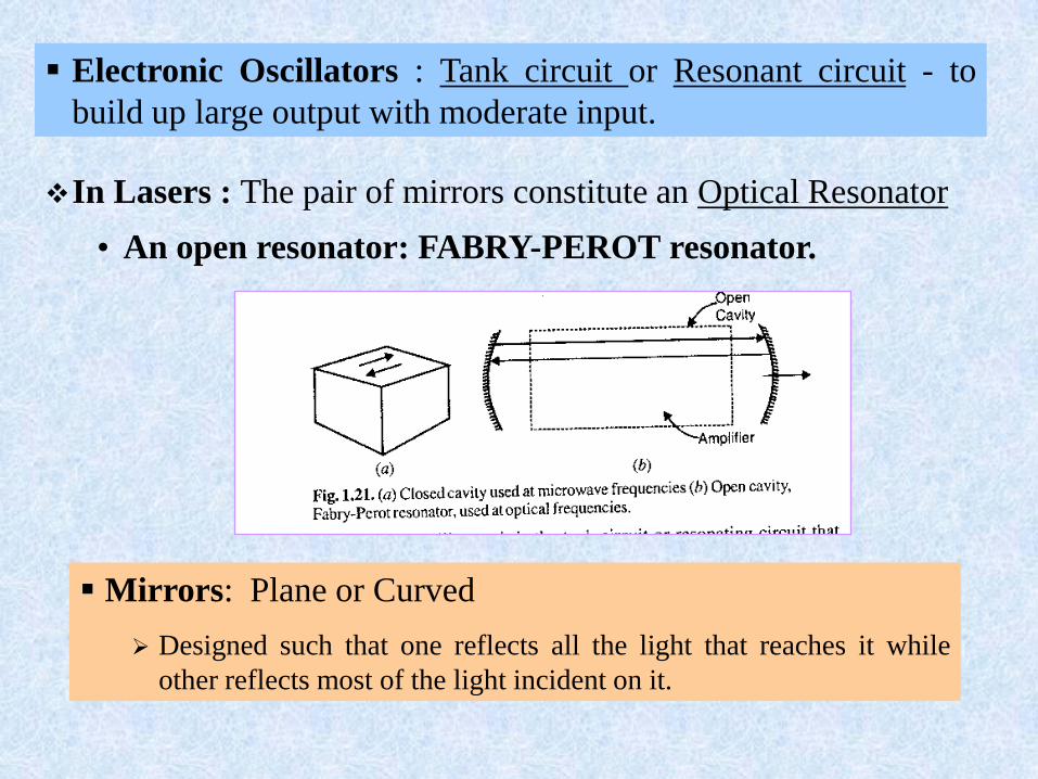
In Lasers : The pair of mirrors constitute an Optical Resonator
• An open resonator: FABRY-PEROT resonator.
Mirrors: Plane or Curved
Designed such that one reflects all the light that reaches it while
other reflects most of the light incident on it.
Electronic Oscillators : Tank circuit or Resonant circuit - to
build up large output with moderate input.
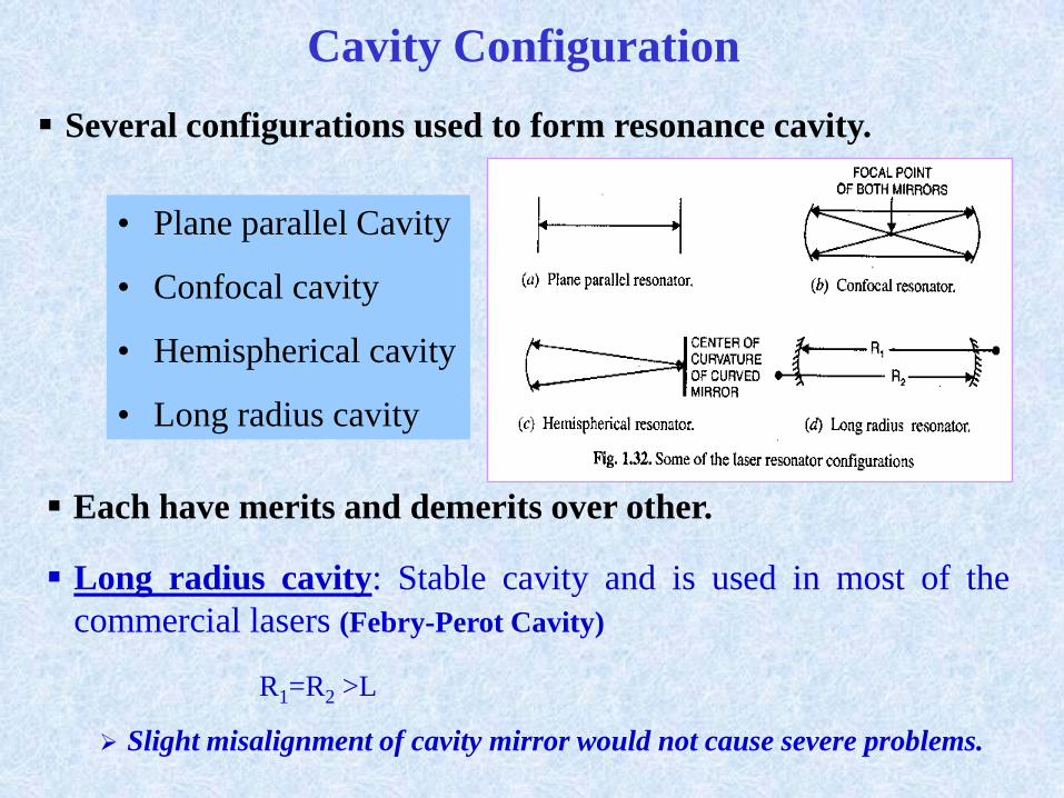
Cavity Configuration
Long radius cavity: Stable cavity and is used in most of the
commercial lasers (Febry-Perot Cavity)
R1=R2 >L
Slight misalignment of cavity mirror would not cause severe problems.
Several configurations used to form resonance cavity.
• Plane parallel Cavity
• Confocal cavity
• Hemispherical cavity
• Long radius cavity
Each have merits and demerits over other.
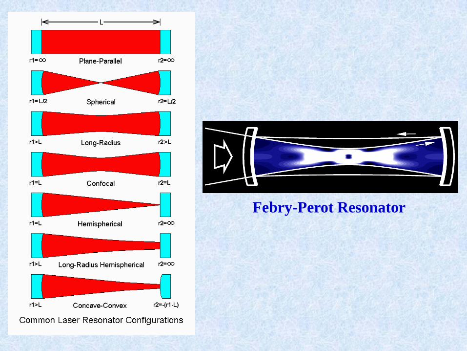
Febry-Perot Resonator
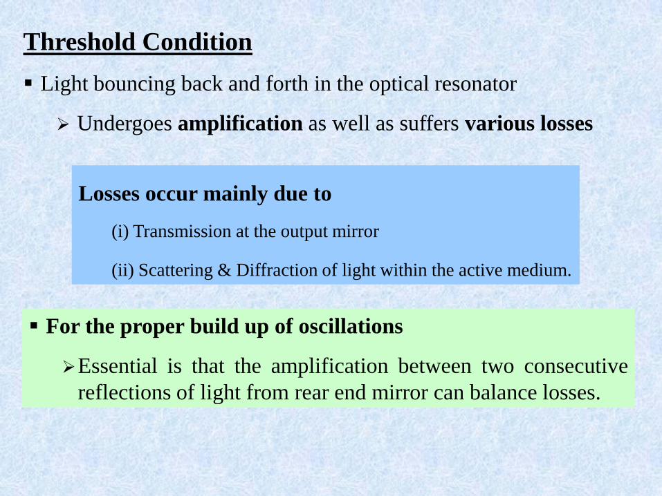
Threshold Condition
Light bouncing back and forth in the optical resonator
Undergoes amplification as well as suffers various losses
Losses occur mainly due to
(i) Transmission at the output mirror
(ii) Scattering & Diffraction of light within the active medium.
For the proper build up of oscillations
Essential is that the amplification between two consecutive
reflections of light from rear end mirror can balance losses.
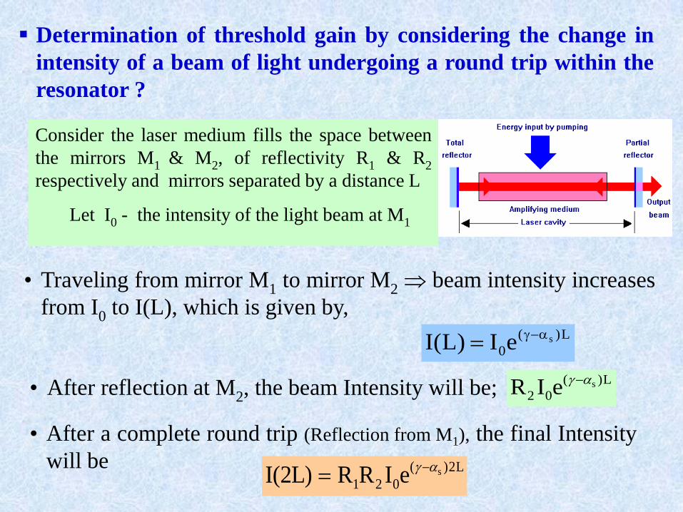
Determination of threshold gain by considering the change in
intensity of a beam of light undergoing a round trip within the
resonator ?
• After reflection at M2, the beam Intensity will be;L)(
02seIR
• After a complete round trip (Reflection from M1), the final Intensity
will be L2)(
021seIRR)L2(I
Consider the laser medium fills the space between
the mirrors M1 & M2, of reflectivity R1 & R2
respectively and mirrors separated by a distance L
Let I0 - the intensity of the light beam at M1
L)(
0seI)L(I
• Traveling from mirror M1 to mirror M2 beam intensity increases
from I0 to I(L), which is given by,
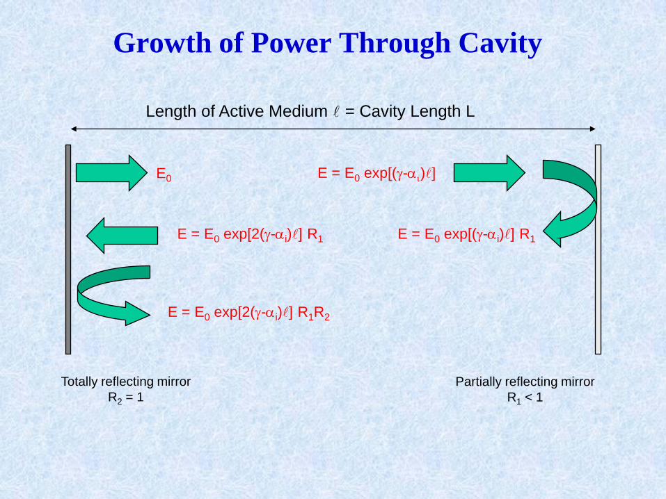
Growth of Power Through Cavity
Length of Active Medium l = Cavity Length L
Totally reflecting mirror
R2 = 1
Partially reflecting mirror
R1 < 1
E0 E = E0 exp[(-i)l]
E = E0 exp[(-i)l] R1E = E0 exp[2(-i)l] R1
E = E0 exp[2(-i)l] R1R2
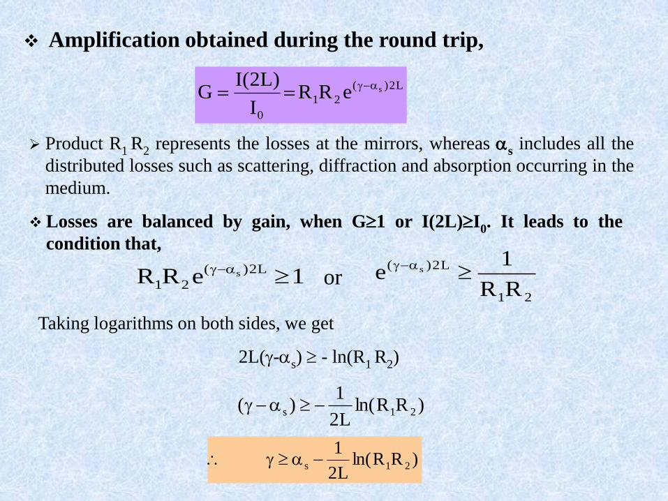
Amplification obtained during the round trip,
L2)(
21
0
seRRI
)L2(IG
Product R1 R2 represents the losses at the mirrors, whereas s includes all the
distributed losses such as scattering, diffraction and absorption occurring in the
medium.
Taking logarithms on both sides, we get
2L(-s) - ln(R1 R2)
)RRln(L2
1)( 21s
)RRln(L2
121s
21
L2)(
RR
1e s
1eRR
L2)(
21s
or
Losses are balanced by gain, when G1 or I(2L)I0. It leads to the
condition that,
21
sRR
1ln
L2
1 Condition for Lasing
Shows that the initial gain must exceed the sum of losses in the
cavity. The condition is used to determine the threshold value of
pumping energy necessary for lasing action.
‘’- Amplification of the laser, dependent on how hard the laser medium
is pumped.
As the pump power is slowly increased, a value of ‘th’ called threshold
value will be reached and the laser starts oscillating.
Threshold value ‘th’ is given by )RR
1ln(
L2
1
21
sth
For the laser to oscillate, > th Threshold condition for lasing
This states the criterion when the net gain would be able to counteract the
effect of losses in the cavity
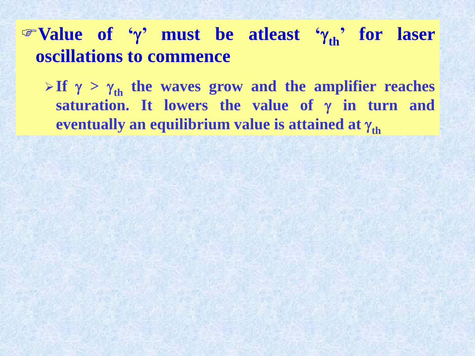
Value of ‘’ must be atleast ‘th’ for laser
oscillations to commence
If > th the waves grow and the amplifier reaches
saturation. It lowers the value of in turn and
eventually an equilibrium value is attained at th

Critical Population Inversion
Quantity, Nth = (N2-N1)th called Critical P.I. or Threshold P .I. density
Minimum population inversion density required to start lasing action and
then to sustain it.
)RRln(L2
1
v
8
v
8N 21s2
sp
2
0
2
thsp
2
0
th
In a system in which mirror and scattering losses are small and laser
medium not being pumped.
A light pulse starting with an original field strength E0 bounces back and
forth between the mirrors. It makes a round trip in a time T = 2L/v.
L2
021 eERR)T(E Electric field after one round trip will be :
The electric field will decay with time and the decaying field will be
ct
t
0eE)T(E
where ‘tc’ represent the cavity decay constant
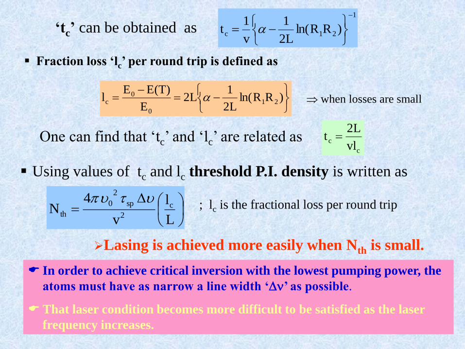
In order to achieve critical inversion with the lowest pumping power, the
atoms must have as narrow a line width ‘’ as possible.
That laser condition becomes more difficult to be satisfied as the laser
frequency increases.
‘tc’ can be obtained as1
21c )RRln(L2
1
v
1t
Fraction loss ‘lc’ per round trip is defined as
)RRln(L2
1L2
E
)T(EEl 21
0
0c when losses are small
One can find that ‘tc’ and ‘lc’ are related as c
cvl
L2t
Using values of tc and lc threshold P.I. density is written as
L
l
v
4N c
2
sp
2
0
th
; lc is the fractional loss per round trip
Lasing is achieved more easily when Nth is small.
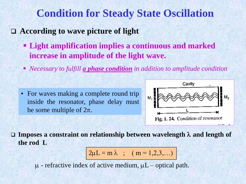
Condition for Steady State Oscillation
According to wave picture of light
Light amplification implies a continuous and marked
increase in amplitude of the light wave.
Necessary to fulfill a phase condition in addition to amplitude condition
• For waves making a complete round trip
inside the resonator, phase delay must
be some multiple of 2.
Imposes a constraint on relationship between wavelength and length of
the rod L
2L = m ; ( m = 1,2,3,…)
- refractive index of active medium, L – optical path.
Condition of resonance between the mirror cavity and
the light waves.
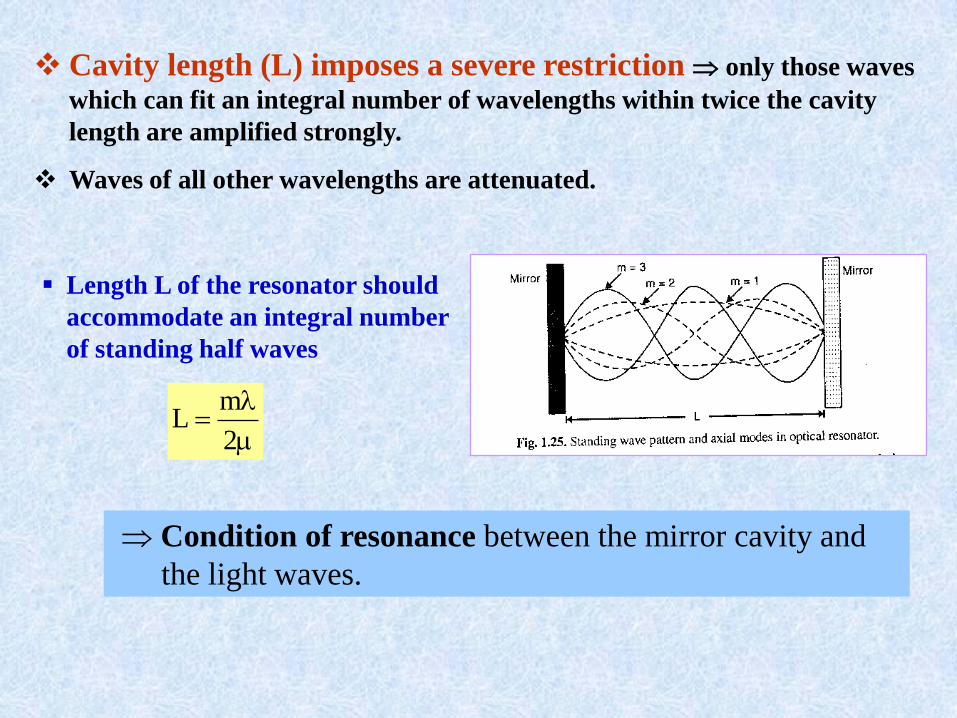
Length L of the resonator should
accommodate an integral number
of standing half waves
2
mL
Cavity length (L) imposes a severe restriction only those waves
which can fit an integral number of wavelengths within twice the cavity
length are amplified strongly.
Waves of all other wavelengths are attenuated.
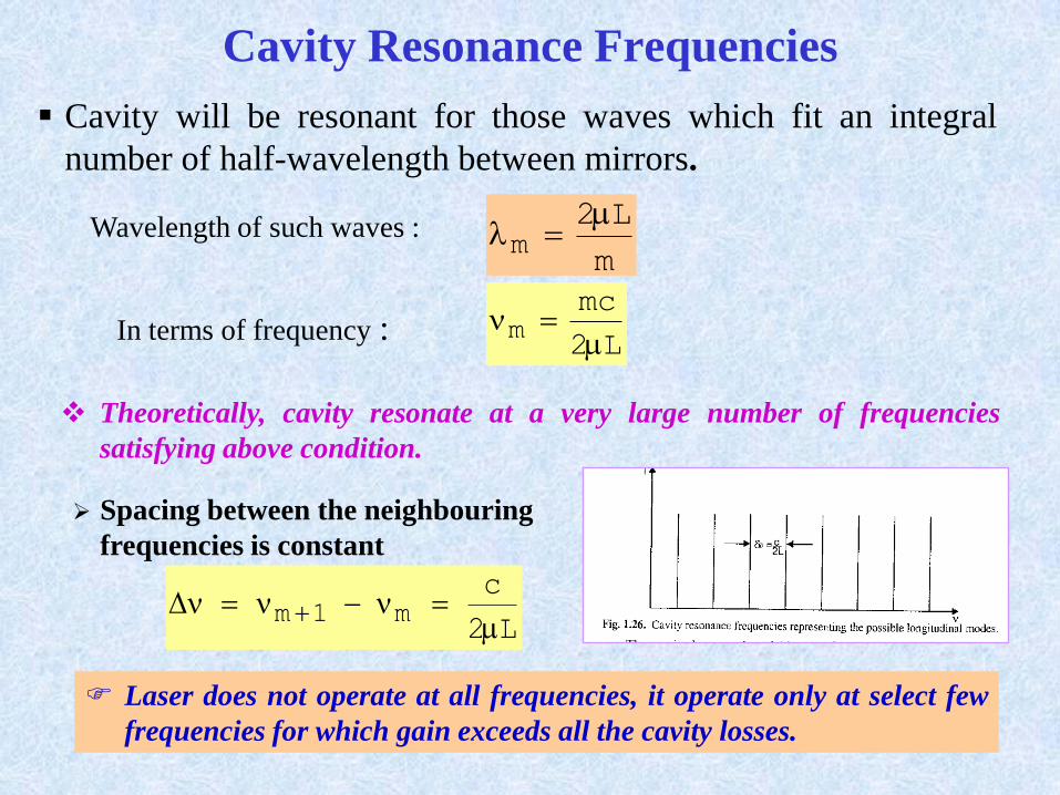
Cavity Resonance Frequencies
Cavity will be resonant for those waves which fit an integral
number of half-wavelength between mirrors.
m
L2m
Wavelength of such waves :
In terms of frequency :L2
mcm
Theoretically, cavity resonate at a very large number of frequencies
satisfying above condition.
Spacing between the neighbouring
frequencies is constant
L2
cm1m
Laser does not operate at all frequencies, it operate only at select few
frequencies for which gain exceeds all the cavity losses.
Gain Saturation
P.I. condition is created in the lasing medium by the pumping agent.
Light of suitable frequency induces transitions from level E2 E1
Gain of the medium exceeds the threshold value and amplification takes place.
Lasing begins and the strength of the light field within the active medium
increases exponentially. The rate at which S.E. take place is proportional to the
strength of the light field present.
Intensity of the light builds up in the medium.
As the intensity of light due to stimulated emission increases, the degree of
P.I. decreases Gain will decrease.
Gain ultimately settles down at a value where the rate of production of the
excess inverted population is balanced by the rate of decrease through
stimulated emission.
It happens when the gain just balances the losses in the medium
A threshold value Nth corresponding to this situation.
In Steady State Condition
N2-N1 remain equal to Nth ; Even though the pumping rate is greater
than the threshold pumping rate.
TO SUM UP
Light amplification in a laser medium cannot increase without limit. As
the amplification increases, there is a companion decrease in the
population at the upper level. As a result, the population inversion is
reduced, the number of stimulated emission events decrease and the
amplification goes down.
Reduction in P.I. and consequent self-adjustment of gain caused
by the presence of light field is called Gain Saturation.
The gain saturation is the mechanism, which adjusts the gain
to a value where it just balances the losses in the cavity so
that steady oscillations can result.
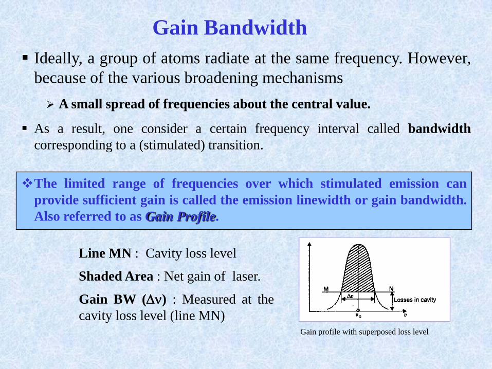
Gain Bandwidth
Ideally, a group of atoms radiate at the same frequency. However,
because of the various broadening mechanisms
A small spread of frequencies about the central value.
As a result, one consider a certain frequency interval called bandwidth
corresponding to a (stimulated) transition.
The limited range of frequencies over which stimulated emission can
provide sufficient gain is called the emission linewidth or gain bandwidth.
Also referred to as Gain Profile.
Gain profile with superposed loss level
Line MN : Cavity loss level
Shaded Area : Net gain of laser.
Gain BW () : Measured at the
cavity loss level (line MN)
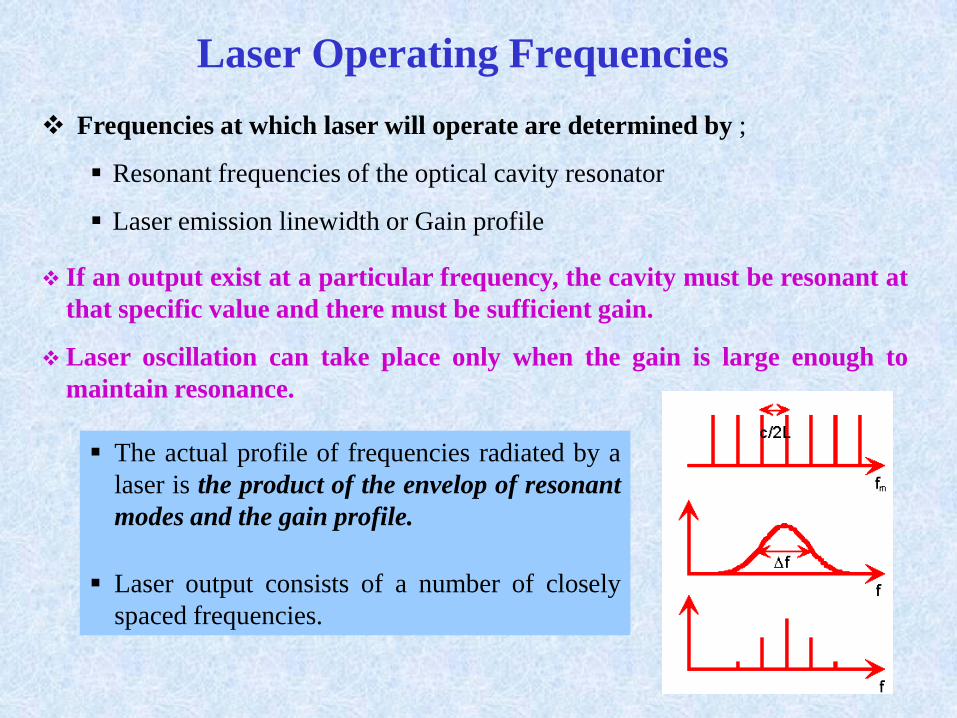
Laser Operating Frequencies
Frequencies at which laser will operate are determined by ;
Resonant frequencies of the optical cavity resonator
Laser emission linewidth or Gain profile
If an output exist at a particular frequency, the cavity must be resonant at
that specific value and there must be sufficient gain.
Laser oscillation can take place only when the gain is large enough to
maintain resonance.
The actual profile of frequencies radiated by a
laser is the product of the envelop of resonant
modes and the gain profile.
Laser output consists of a number of closely
spaced frequencies.
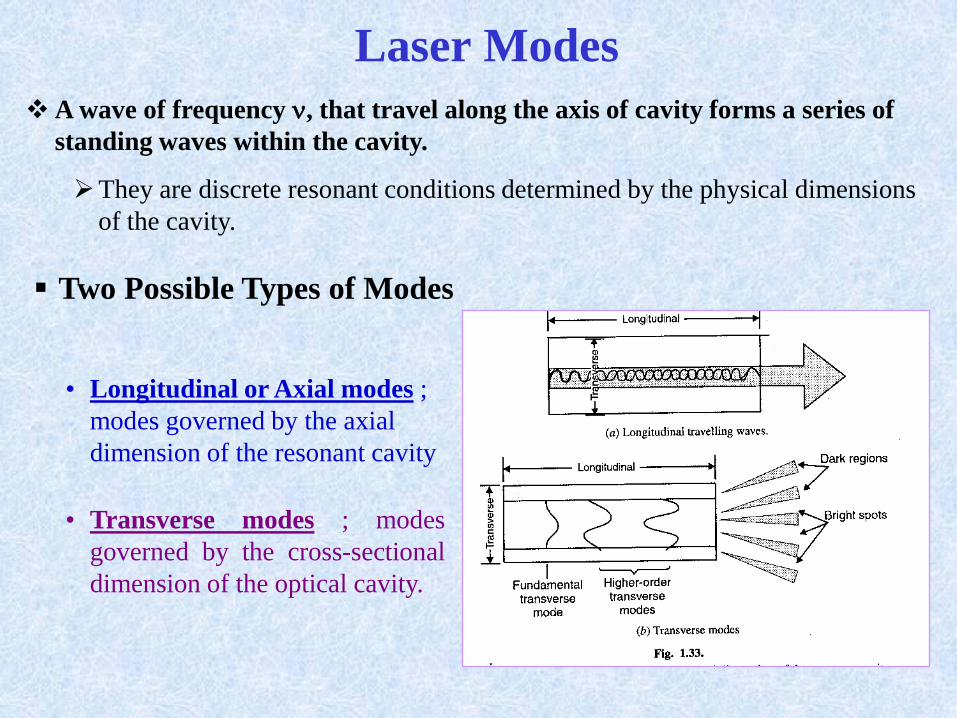
Laser Modes
A wave of frequency , that travel along the axis of cavity forms a series of
standing waves within the cavity.
They are discrete resonant conditions determined by the physical dimensions
of the cavity.
Two Possible Types of Modes
• Longitudinal or Axial modes ;
modes governed by the axial
dimension of the resonant cavity
• Transverse modes ; modes
governed by the cross-sectional
dimension of the optical cavity.
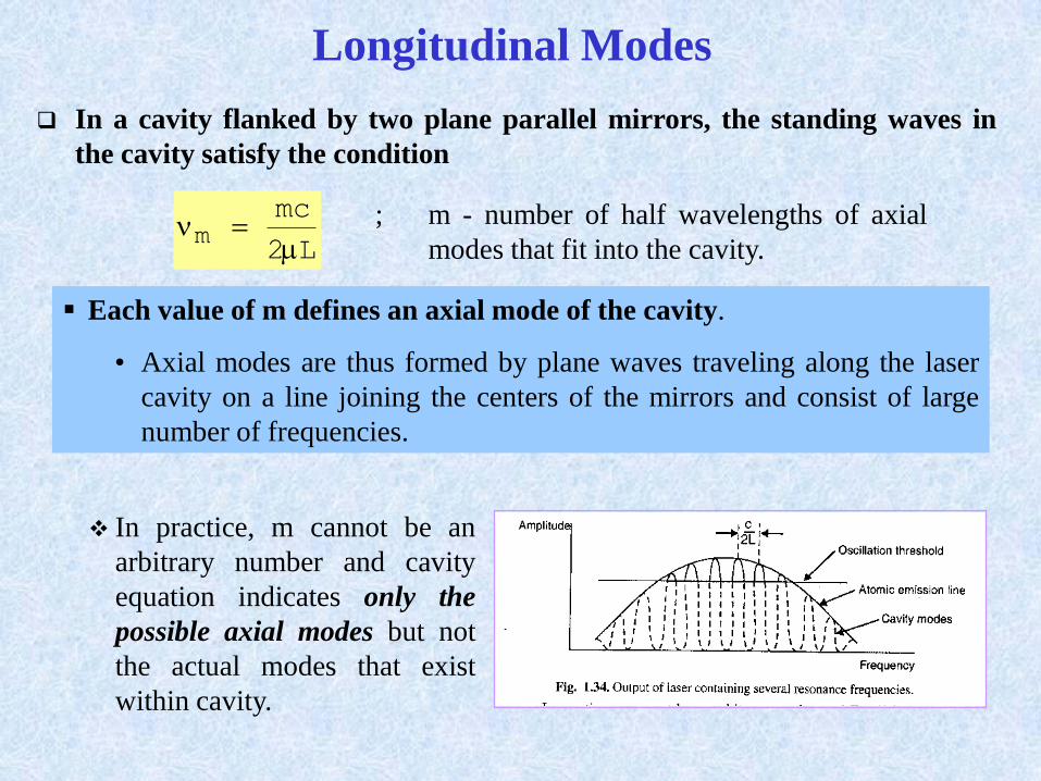
Longitudinal Modes
In a cavity flanked by two plane parallel mirrors, the standing waves in
the cavity satisfy the condition
L2
mcm
; m - number of half wavelengths of axial
modes that fit into the cavity.
Each value of m defines an axial mode of the cavity.
• Axial modes are thus formed by plane waves traveling along the laser
cavity on a line joining the centers of the mirrors and consist of large
number of frequencies.
In practice, m cannot be an
arbitrary number and cavity
equation indicates only the
possible axial modes but not
the actual modes that exist
within cavity.

Frequency separation, , between adjacent modes
L2
c
; is independent of m
Frequency separation of adjacent mode is the same irrespective of their
actual frequencies.
ALL THE AXIAL MODES CONTRIBUTE OT A SINGLE
SPOT OF LIGHT IN THE LASER SPOT.
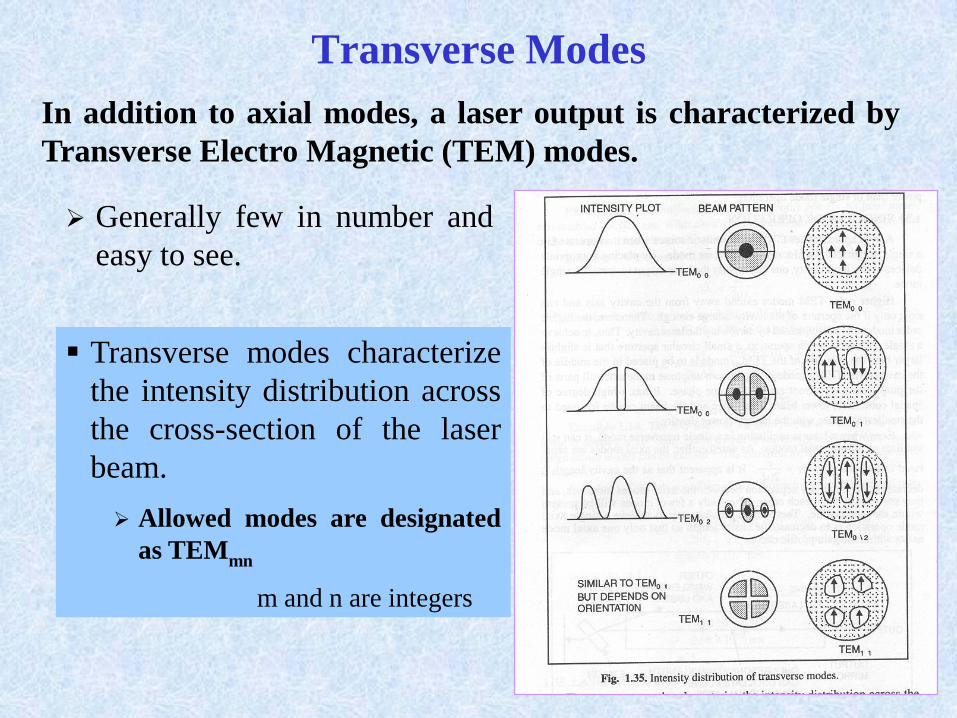
Transverse Modes
In addition to axial modes, a laser output is characterized by
Transverse Electro Magnetic (TEM) modes.
Generally few in number and
easy to see.
Transverse modes characterize
the intensity distribution across
the cross-section of the laser
beam.
Allowed modes are designated
as TEMmn
m and n are integers
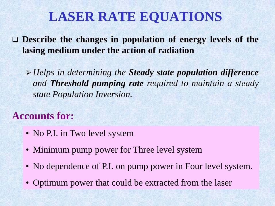
LASER RATE EQUATIONS
Describe the changes in population of energy levels of the
lasing medium under the action of radiation
Helps in determining the Steady state population difference
and Threshold pumping rate required to maintain a steady
state Population Inversion.
• No P.I. in Two level system
• Minimum pump power for Three level system
• No dependence of P.I. on pump power in Four level system.
• Optimum power that could be extracted from the laser
Accounts for:
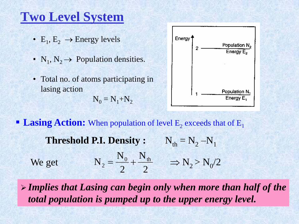
Two Level System
• E1, E2 Energy levels
• N1, N2 Population densities.
• Total no. of atoms participating in
lasing action
N0 = N1+N2
Lasing Action: When population of level E2 exceeds that of E1
Threshold P.I. Density : Nth = N2 –N1
We get2
N
2
NN th0
2 N2 > N0/2
Implies that Lasing can begin only when more than half of the
total population is pumped up to the upper energy level.
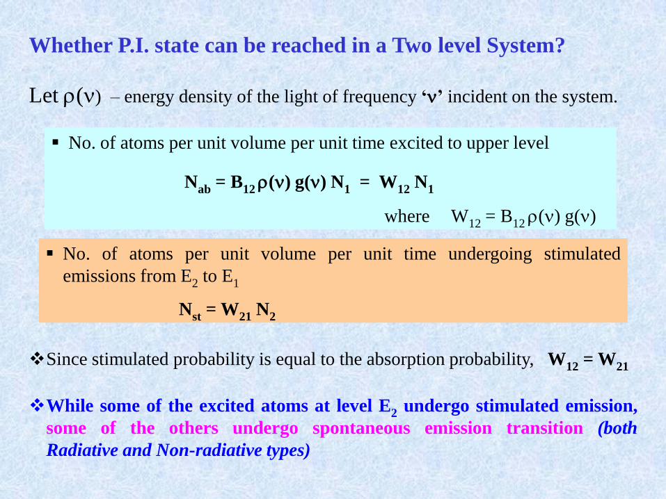
Whether P.I. state can be reached in a Two level System?
Let () – energy density of the light of frequency ‘’ incident on the system.
No. of atoms per unit volume per unit time excited to upper level
Nab = B12() g() N1 = W12 N1
where W12 = B12() g()
No. of atoms per unit volume per unit time undergoing stimulated
emissions from E2 to E1
Nst = W21 N2
Since stimulated probability is equal to the absorption probability, W12 = W21
While some of the excited atoms at level E2 undergo stimulated emission,
some of the others undergo spontaneous emission transition (both
Radiative and Non-radiative types)
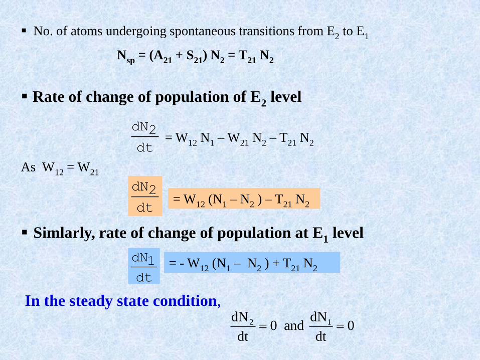
No. of atoms undergoing spontaneous transitions from E2 to E1
Nsp = (A21 + S21) N2 = T21 N2
Rate of change of population of E2 level
dt
2dN= W12 N1 – W21 N2 – T21 N2
As W12 = W21
= W12 (N1 – N2 ) – T21 N2dt
2dN
= - W12 (N1 – N2 ) + T21 N2
dt
1dN
Simlarly, rate of change of population at E1 level
In the steady state condition,
0dt
dNand0
dt
dN 12
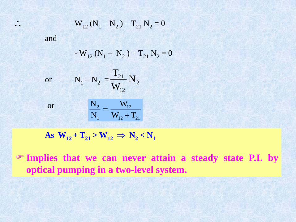
W12 (N1 – N2 ) – T21 N2 = 0
and
- W12 (N1 – N2 ) + T21 N2 = 0
2
12
21 NW
Tor N1 – N2 =
or
2112
12
1
2
TW
W
N
N
As W12 + T21 > W12 N2 < N1
Implies that we can never attain a steady state P.I. by
optical pumping in a two-level system.
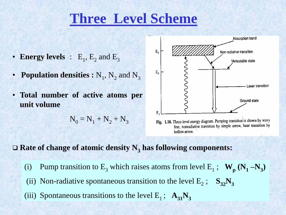
Three Level Scheme
• Energy levels : E1, E2 and E3
• Population densities : N1, N2 and N3
• Total number of active atoms per
unit volume
N0 = N1 + N2 + N3
Rate of change of atomic density N3 has following components:
(i) Pump transition to E3 which raises atoms from level E1 ; Wp (N1 –N3)
(ii) Non-radiative spontaneous transition to the level E2 ; S32N3
(iii) Spontaneous transitions to the level E1 ; A31N3
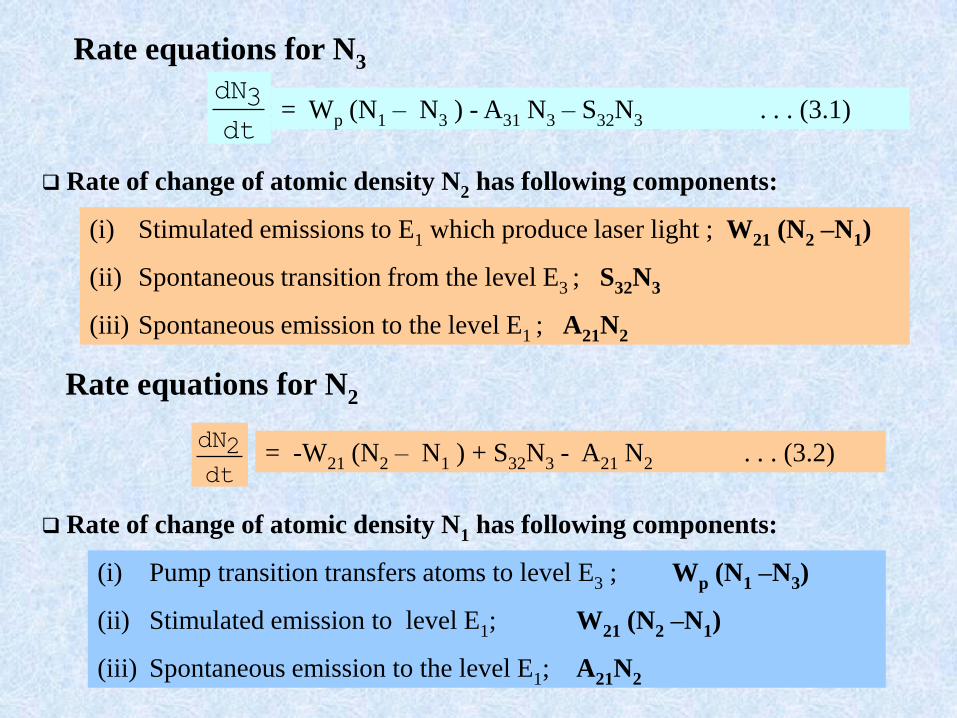
Rate equations for N3
= Wp (N1 – N3 ) - A31 N3 – S32N3 . . . (3.1)dt
3dN
Rate of change of atomic density N2 has following components:
(i) Stimulated emissions to E1 which produce laser light ; W21 (N2 –N1)
(ii) Spontaneous transition from the level E3 ; S32N3
(iii) Spontaneous emission to the level E1 ; A21N2
Rate equations for N2
= -W21 (N2 – N1 ) + S32N3 - A21 N2 . . . (3.2)dt
2dN
Rate of change of atomic density N1 has following components:
(i) Pump transition transfers atoms to level E3 ; Wp (N1 –N3)
(ii) Stimulated emission to level E1; W21 (N2 –N1)
(iii) Spontaneous emission to the level E1; A21N2
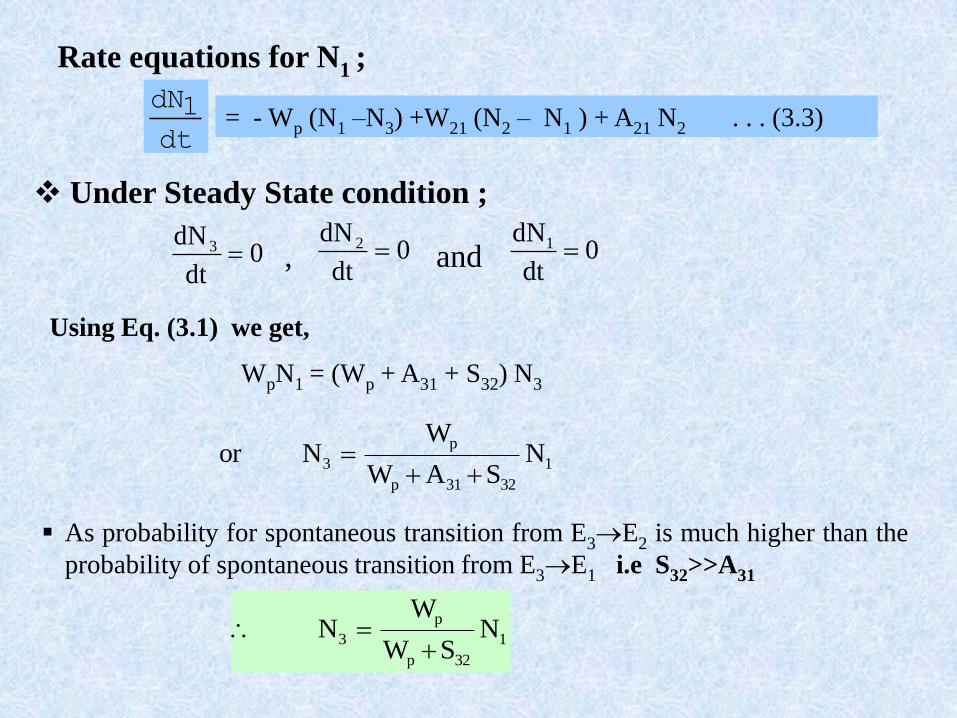
Rate equations for N1 ;
= - Wp (N1 –N3) +W21 (N2 – N1 ) + A21 N2 . . . (3.3)dt
1dN
Under Steady State condition ;
0dt
dN 3 0dt
dN 2 0dt
dN1 , and
Using Eq. (3.1) we get,
WpN1 = (Wp + A31 + S32) N3
1
3231p
p
3 NSAW
WNor
As probability for spontaneous transition from E3E2 is much higher than the
probability of spontaneous transition from E3E1 i.e S32>>A31
1
32p
p
3 NSW
WN
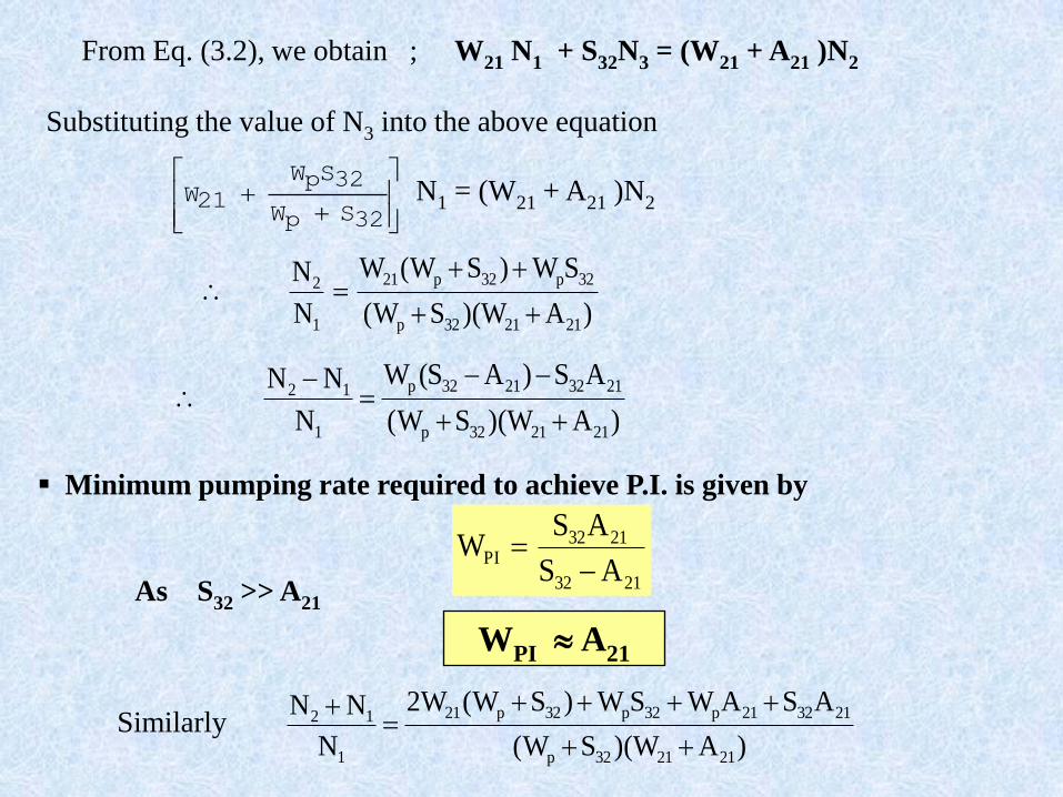
From Eq. (3.2), we obtain ; W21 N1 + S32N3 = (W21 + A21 )N2
Minimum pumping rate required to achieve P.I. is given by
2132
2132PI
AS
ASW
As S32 >> A21
WPI A21
32SpW
32SpW
21W N1 = (W21 + A21 )N2
)AW)(SW(
SW)SW(W
N
N
212132p
32p32p21
1
2
)AW)(SW(
AS)AS(W
N
NN
212132p
21322132p
1
12
Substituting the value of N3 into the above equation
Similarly)AW)(SW(
ASAWSW)SW(W2
N
NN
212132p
213221p32p32p21
1
12
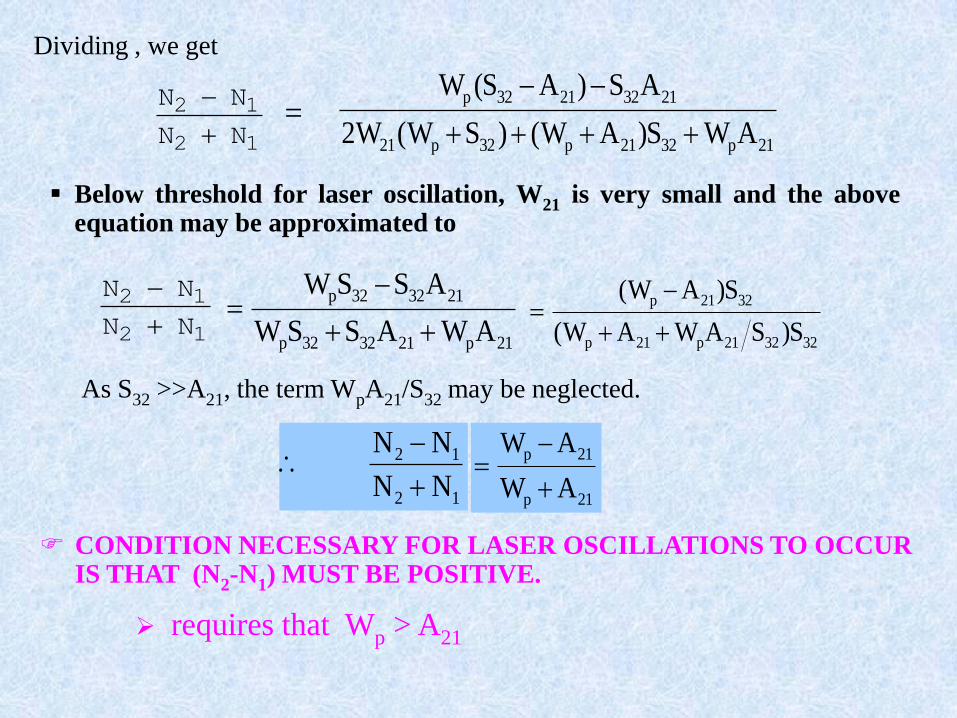
Dividing , we get
21p3221p32p21
21322132p
AWS)AW()SW(W2
AS)AS(W
12
12
NN
NN
=
Below threshold for laser oscillation, W21 is very small and the aboveequation may be approximated to
12
12
NN
NN
21p213232p
213232p
AWASSW
ASSW
323221p21p
3221p
S)SAWAW(
S)AW(
As S32 >>A21, the term WpA21/S32 may be neglected.
12
12
NN
NN
21p
21p
AW
AW
CONDITION NECESSARY FOR LASER OSCILLATIONS TO OCCUR IS THAT (N2-N1) MUST BE POSITIVE.
requires that Wp > A21
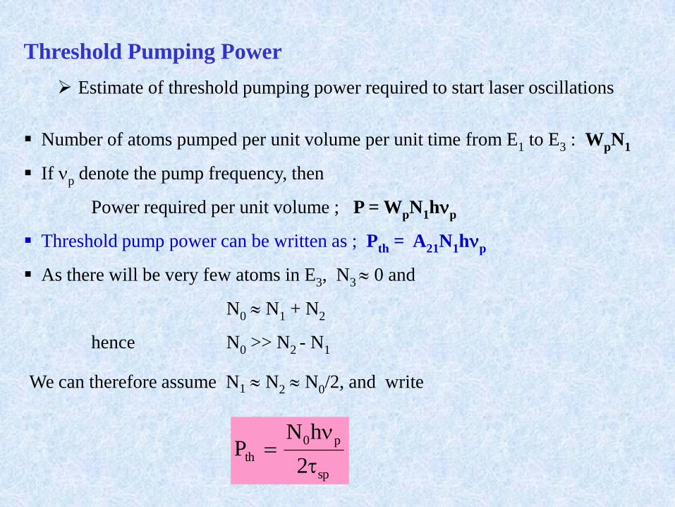
Threshold Pumping Power
Estimate of threshold pumping power required to start laser oscillations
Number of atoms pumped per unit volume per unit time from E1 to E3 : WpN1
If p denote the pump frequency, then
Power required per unit volume ; P = WpN1hp
Threshold pump power can be written as ; Pth = A21N1hp
As there will be very few atoms in E3, N3 0 and
N0 N1 + N2
hence N0 >> N2 - N1
We can therefore assume N1 N2 N0/2, and write
sp
p0
th2
hNP
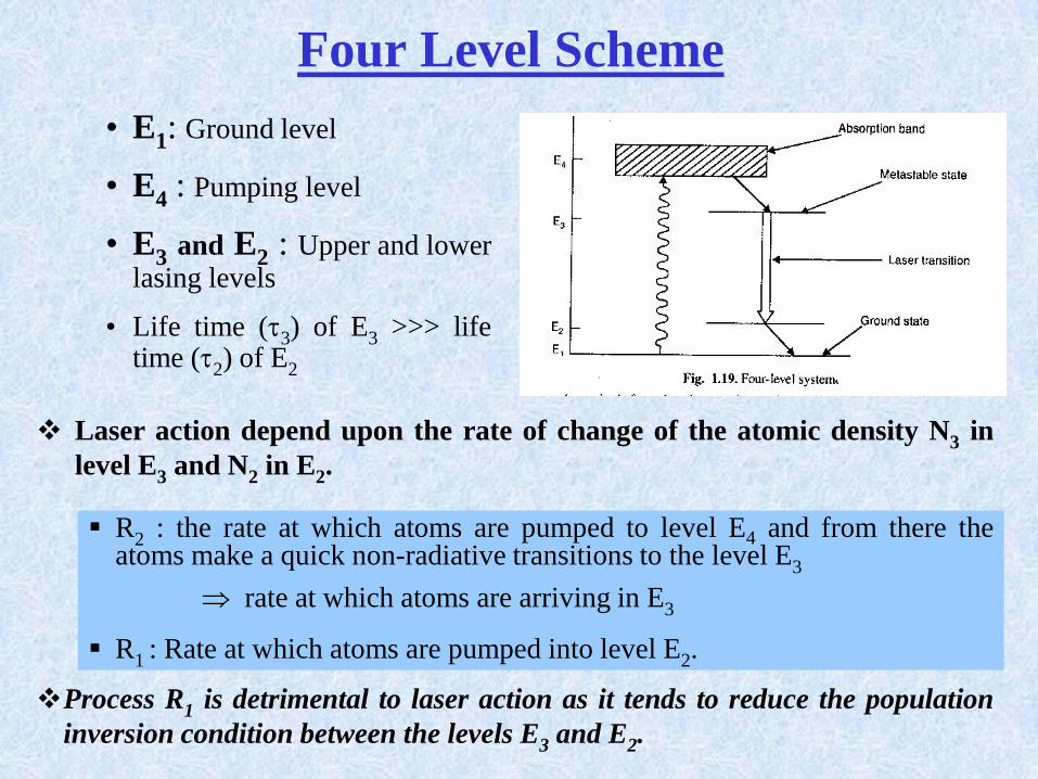
Four Level Scheme
• E1: Ground level
• E4 : Pumping level
• E3 and E2 : Upper and lowerlasing levels
• Life time (3) of E3 >>> lifetime (2) of E2
Process R1 is detrimental to laser action as it tends to reduce the population
inversion condition between the levels E3 and E2.
R2 : the rate at which atoms are pumped to level E4 and from there theatoms make a quick non-radiative transitions to the level E3
rate at which atoms are arriving in E3
R1 : Rate at which atoms are pumped into level E2.
Laser action depend upon the rate of change of the atomic density N3 in
level E3 and N2 in E2.
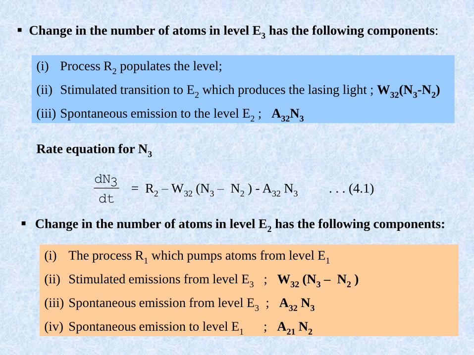
Change in the number of atoms in level E3 has the following components:
(i) Process R2 populates the level;
(ii) Stimulated transition to E2 which produces the lasing light ; W32(N3-N2)
(iii) Spontaneous emission to the level E2 ; A32N3
Rate equation for N3
dt
3dN= R2 – W32 (N3 – N2 ) - A32 N3 . . . (4.1)
Change in the number of atoms in level E2 has the following components:
(i) The process R1 which pumps atoms from level E1
(ii) Stimulated emissions from level E3 ; W32 (N3 – N2 )
(iii) Spontaneous emission from level E3 ; A32 N3
(iv) Spontaneous emission to level E1 ; A21 N2
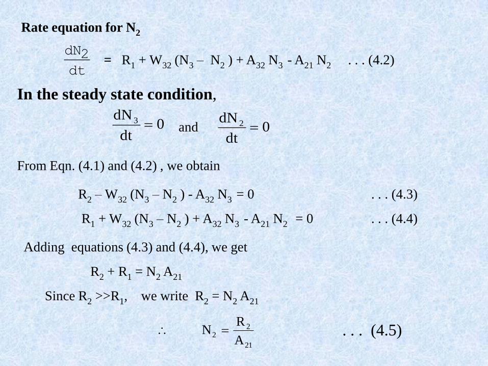
Rate equation for N2
dt
2dN= R1 + W32 (N3 – N2 ) + A32 N3 - A21 N2 . . . (4.2)
In the steady state condition,
0dt
dN 3 0dt
dN 2 and
From Eqn. (4.1) and (4.2) , we obtain
Adding equations (4.3) and (4.4), we get
R2 – W32 (N3 – N2 ) - A32 N3 = 0 . . . (4.3)
R1 + W32 (N3 – N2 ) + A32 N3 - A21 N2 = 0 . . . (4.4)
R2 + R1 = N2 A21
Since R2 >>R1, we write R2 = N2 A21
21
22
A
RN . . . (4.5)
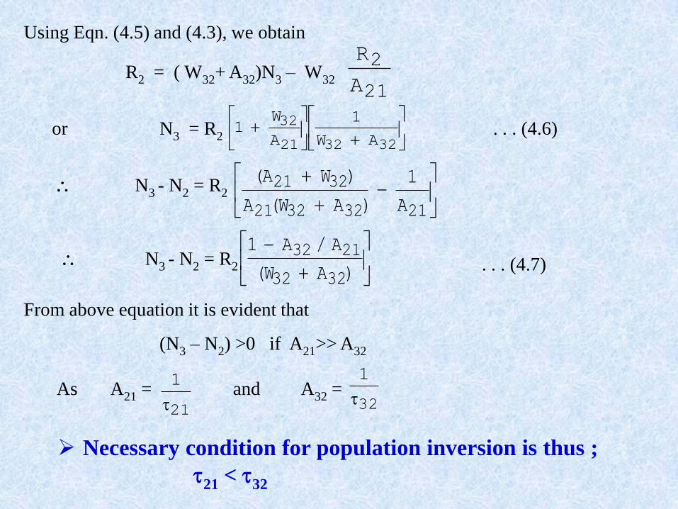
Using Eqn. (4.5) and (4.3), we obtain
R2 = ( W32+ A32)N3 – W32 21
2
A
R
323221
32
AW
1
A
W1or N3 = R2 . . . (4.6)
21323221
3221
A
1
)AW(A
)WA( N3 - N2 = R2
N3 - N2 = R2
)AW(
A/A1
3232
2132. . . (4.7)
From above equation it is evident that
(N3 – N2) >0 if A21>> A32
As A21 = and A32 =21
1
32
1
Necessary condition for population inversion is thus ;
21 < 32
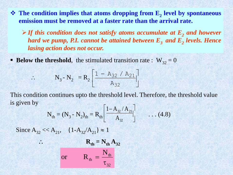
The condition implies that atoms dropping from E2 level by spontaneous
emission must be removed at a faster rate than the arrival rate.
If this condition does not satisfy atoms accumulate at E2 and however
hard we pump, P.I. cannot be attained between E3 and E2 levels. Hence
lasing action does not occur.
Below the threshold, the stimulated transition rate : W32 = 0
32
2132
A
A/A1 N3 - N2 = R2
This condition continues upto the threshold level. Therefore, the threshold value
is given by
Nth = (N3 - N2)th = Rth
32
2132
A
A/A1. . . (4.8)
Since A32 << A21, {1-A32/A21} 1
Rth = Nth A32
32
thth
NRor
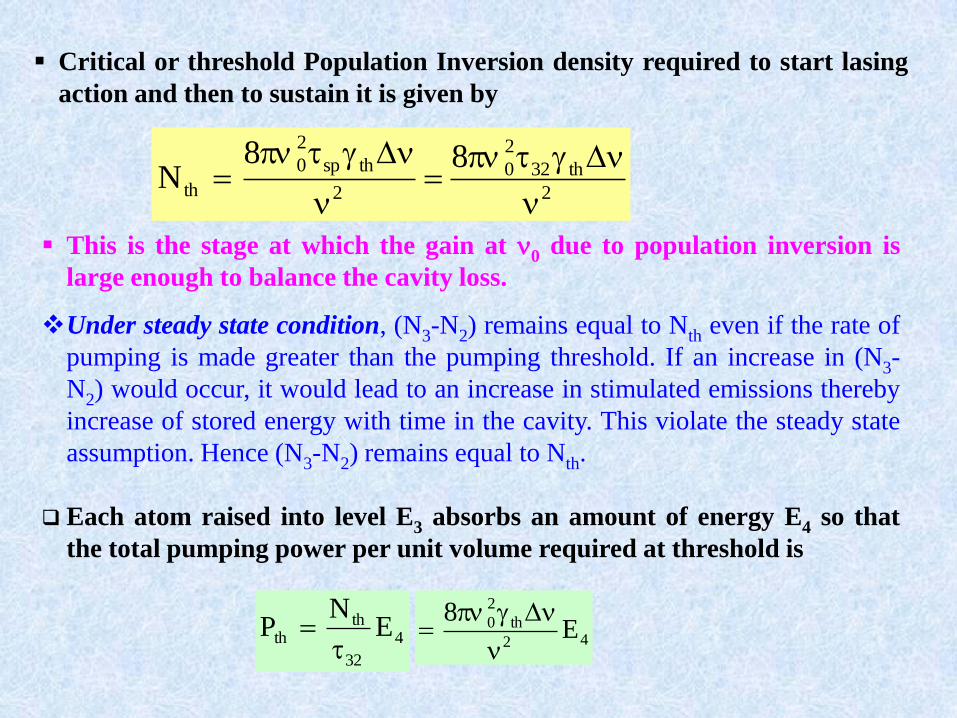
Critical or threshold Population Inversion density required to start lasing
action and then to sustain it is given by
2
th32
2
0
2
thsp
2
0
th
88N
This is the stage at which the gain at 0 due to population inversion is
large enough to balance the cavity loss.
Under steady state condition, (N3-N2) remains equal to Nth even if the rate of
pumping is made greater than the pumping threshold. If an increase in (N3-
N2) would occur, it would lead to an increase in stimulated emissions thereby
increase of stored energy with time in the cavity. This violate the steady state
assumption. Hence (N3-N2) remains equal to Nth.
Each atom raised into level E3 absorbs an amount of energy E4 so that
the total pumping power per unit volume required at threshold is
4
32
thth E
NP
42
th
2
0 E8
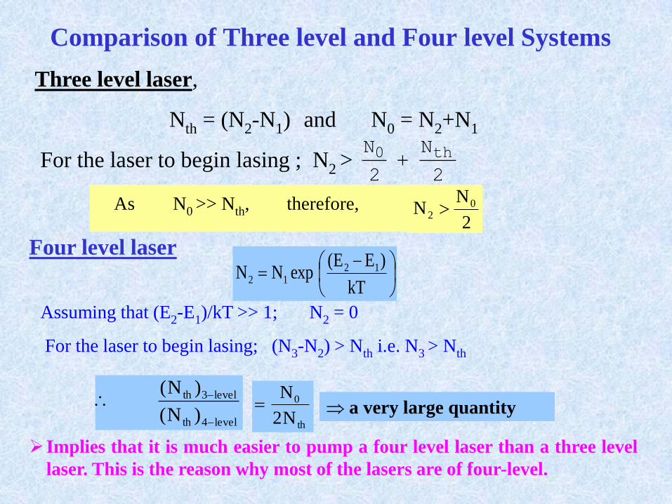
Comparison of Three level and Four level Systems
Three level laser,
Nth = (N2-N1) and N0 = N2+N1
For the laser to begin lasing ; N2 >2
N
2
N th0
As N0 >> Nth, therefore,2
NN 0
2
Four level laser
kT
)EE(expNN 12
12
Assuming that (E2-E1)/kT >> 1; N2 = 0
For the laser to begin lasing; (N3-N2) > Nth i.e. N3 > Nth
level4th
level3th
)N(
)N(
th
0
N2
N a very large quantity
Implies that it is much easier to pump a four level laser than a three level
laser. This is the reason why most of the lasers are of four-level.
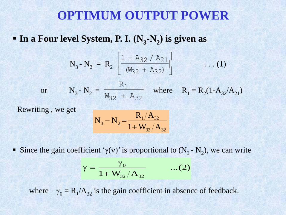
OPTIMUM OUTPUT POWER
In a Four level System, P. I. (N3-N2) is given as
)AW(
A/A1
3232
2132N3 - N2 = R2 . . . (1)
3232
1
AW
R
or N3 - N2 = where R1 = R2(1-A32/A21)
Rewriting , we get
3232
32123
AW1
ARNN
Since the gain coefficient ‘()’ is proportional to (N3 - N2), we can write
)2(...AW1 3232
0
where 0 = R1/A32 is the gain coefficient in absence of feedback.
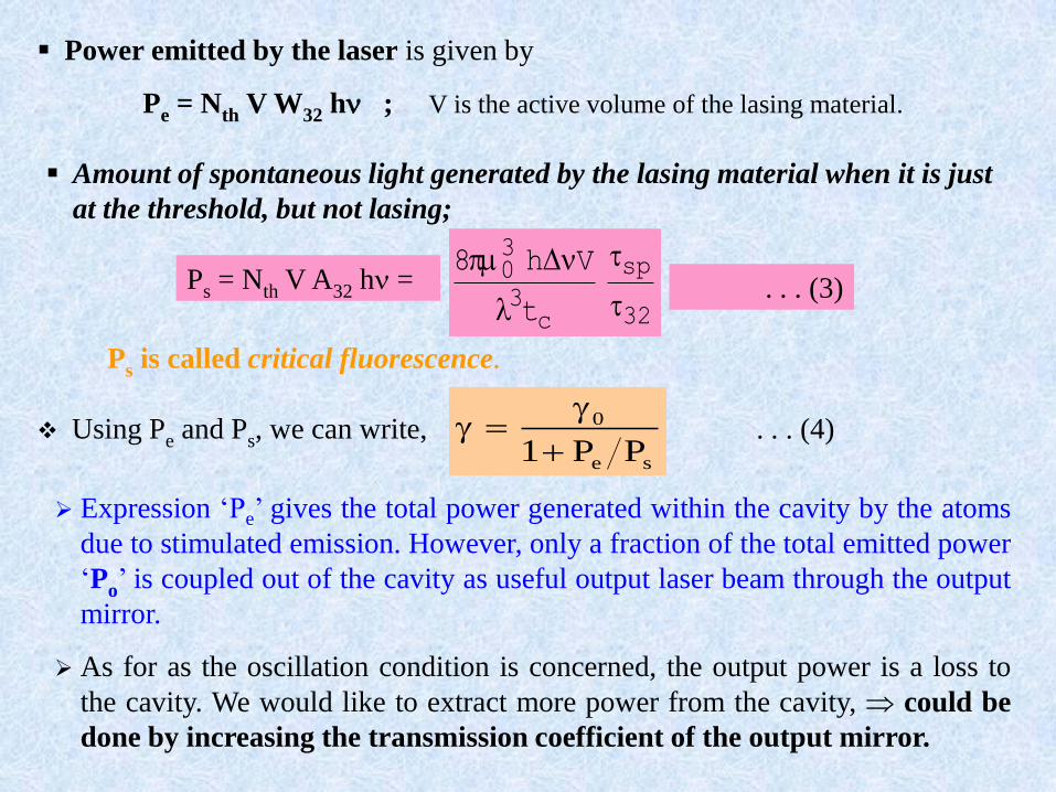
Power emitted by the laser is given by
Pe = Nth V W32 h ; V is the active volume of the lasing material.
Using Pe and Ps, we can write,se
0
PP1
. . . (4)
Expression ‘Pe’ gives the total power generated within the cavity by the atoms
due to stimulated emission. However, only a fraction of the total emitted power
‘Po’ is coupled out of the cavity as useful output laser beam through the output
mirror.
As for as the oscillation condition is concerned, the output power is a loss to
the cavity. We would like to extract more power from the cavity, could be
done by increasing the transmission coefficient of the output mirror.
32
sp
c3
30
t
Vh8
Ps = Nth V A32 h = . . . (3)
Ps is called critical fluorescence.
Amount of spontaneous light generated by the lasing material when it is just
at the threshold, but not lasing;
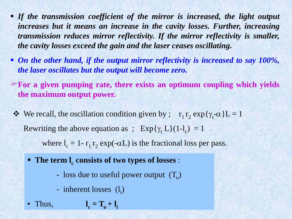
If the transmission coefficient of the mirror is increased, the light output
increases but it means an increase in the cavity losses. Further, increasing
transmission reduces mirror reflectivity. If the mirror reflectivity is smaller,
the cavity losses exceed the gain and the laser ceases oscillating.
On the other hand, if the output mirror reflectivity is increased to say 100%,
the laser oscillates but the output will become zero.
For a given pumping rate, there exists an optimum coupling which yields
the maximum output power.
We recall, the oscillation condition given by ; r1 r2 exp{t-}L = 1
Rewriting the above equation as ; Exp{t L}(1-lc) = 1
where lc = 1- r1 r2 exp(-L) is the fractional loss per pass.
The term lc consists of two types of losses :
- loss due to useful power output (To)
- inherent losses (li)
• Thus, lc = To + li
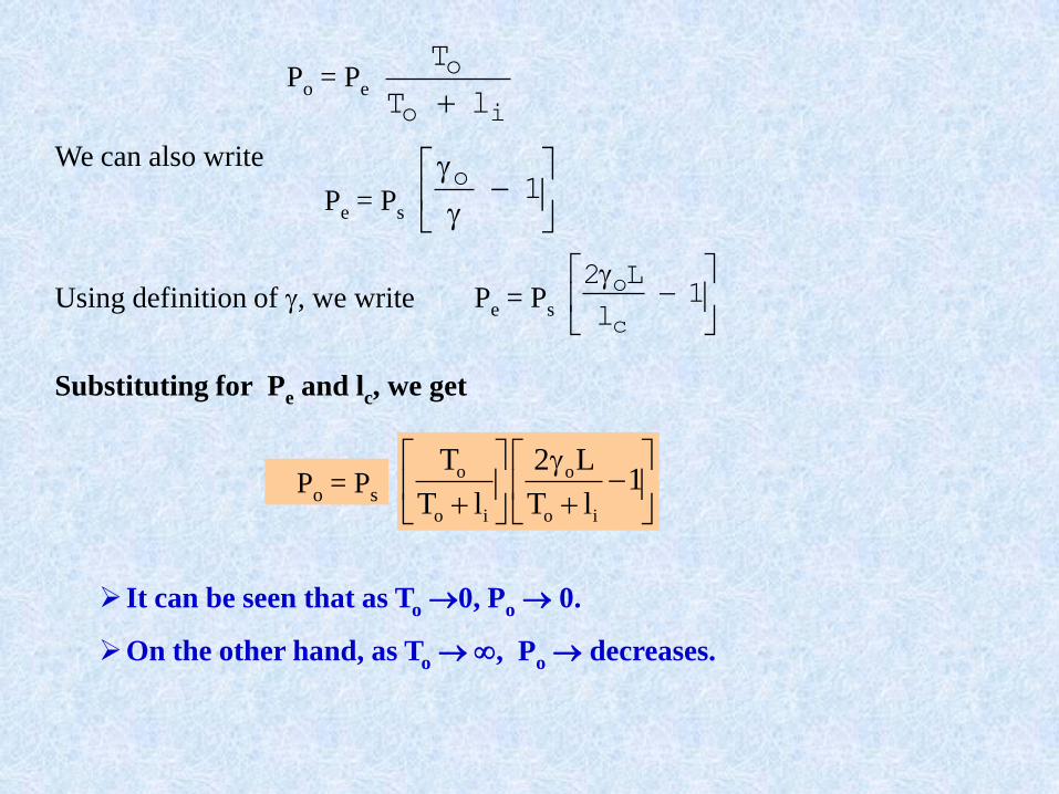
io
o
lT
T
Po = Pe
We can also write
1
oPe = Ps
Using definition of , we write
1
l
L2
c
oPe = Ps
Substituting for Pe and lc, we get
1
lT
L2
lT
T
io
o
io
oPo = Ps
It can be seen that as To 0, Po 0.
On the other hand, as To , Po decreases.
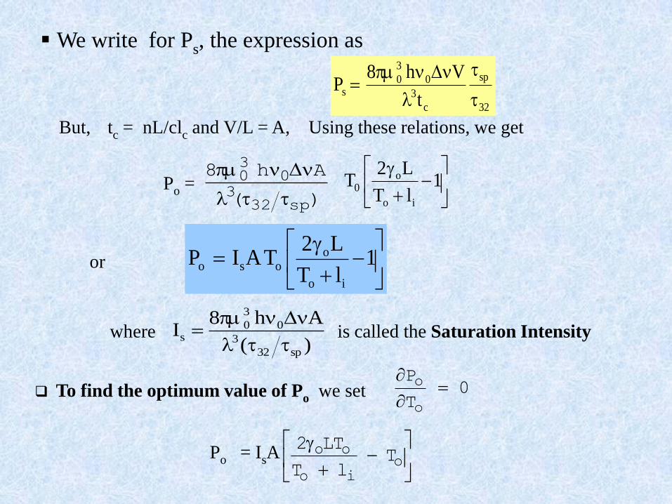
32
sp
c
3
0
3
0s
t
Vh8P
We write for Ps, the expression as
But, tc = nL/clc and V/L = A, Using these relations, we get
)(
Ah8
sp323
030
1
lT
L2T
io
o0Po =
1
lT
L2TAIP
io
oosoor
)(
Ah8I
sp32
3
0
3
0s
is called the Saturation Intensitywhere
To find the optimum value of Po we set 0T
P
o
o
o
io
oo TlT
LT2Po = IsA
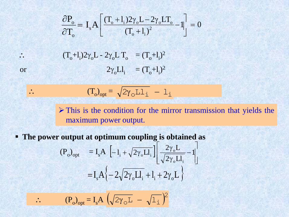
01)lT(
LT2L2)lT(2
io
oooio
AI
T
Ps
o
o
(To+li)2oL - 2oL To = (To+li)2
or 2oLli = (To+li)2
(To)opt = iio lLl2
This is the condition for the mirror transmission that yields the
maximum power output.
1
Ll2
L2Ll2l
io
oioi
(Po)opt = IsA
L2lLl22AI oiios
2io lL2 (Po)opt = IsA
The power output at optimum coupling is obtained as
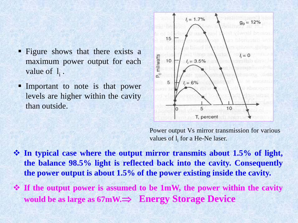
Figure shows that there exists a
maximum power output for each
value of li .
Important to note is that power
levels are higher within the cavity
than outside.
Power output Vs mirror transmission for various
values of li for a He-Ne laser.
In typical case where the output mirror transmits about 1.5% of light,
the balance 98.5% light is reflected back into the cavity. Consequently
the power output is about 1.5% of the power existing inside the cavity.
If the output power is assumed to be 1mW, the power within the cavity
would be as large as 67mW. Energy Storage Device
References:
1. LASERS: Theory and Applications; MN Avadhanulu, S. Chand
& Company Ltd.
2. Lasers & Optical Instrumentation; S.Nagabhushana and N.
Sathyanarayana, IK International Publishing House (P) Ltd.
3. http://www.colorado.edu/physics/lasers/
4. www.Google.co.in/Search engine