Embed Size (px)
Citation preview
AD-AO92 502 HARRY DIAMOND LABS ADELPHI ND F/6 20/5UNSTABLE-RESONATOR AND OUTPUT-COUPLING DESIGN STUDY FOR DIFFRAC-ETC(U)OCT 80 C S WILLETT
NCLASSIFIED HDL-TR-1936 NL
IND
1. [LEEEEE

AD A09 2 50 2

UNCLASSIFIEDSECURITY CLASSIFICATION OF THIS PAGE (Ufmmu Date BotOM.0_________________
REPORT DOCUMENTATION PAGE BFRE INTUTOS
1, REPORT HUMIEJR_ Ia. GOVT ACCESSION NO. 3. RECIPIENT'$ CATALOG NUMBER
'.*HDL-TR-19361 fPY 67
-..V ... TP .. &.Jaz E I.U&W5W~i~zE(~Unstable-Resonator and Output-Coupling Tecn. _pa
Design Study for Diffraction Radiation ________
' Generator Near-Millimeter Sources 6. PERFORMING ORG. EOTNME
7. AUTNOR(e) S. CONTRACT OR GRANT NUMBER(s)
IColin S./Willett
9. 11C11OHRMING ORGANIZATION NAMC AND ADDRESS 10. PROGRAM ELEMENT. PROJECTTAIAREA & WORK( UNIT NUMUERS
Harry Diamond Laboratories b
2800 Powder Mill Road Prog. El.: 6.11.0l.AAdelphi. MD 20783 ____________
It. CONTROLLING OFFICE NAME AND ADDRESS 12, I REPORT.DATE
U.S. Army Materiel Develop:Aent and I ___________Readiness Command WOIIIRO PAG~IES~
1,alx aA d~ 22333 25I. ..ONrORIN AGENY AME a ADDRS(It Eflfgtuot to. Cdratola Offloel IS. SECURITY CLASS. (of Ohio repor)
UNCLASSIFIED
IS.. DECL ASSI FIC ATI ON/ DOWN GRAOI NOSC14EOULIE
IS. DISTRIBUTION STATEMENT (of this Report)
Approved for public release; distribution unlimited.
17. DISTRNo UTION ST ATEMIEN T (of the abstract anSatd In Block",. It different from Report)
If. SUPPLEMENTARY NOTES
HDL Project: A10938DRCMS Code: 611101.91.AO0llDA Project-: 11,161i01A91
IS. KEY WORDS (Cwti on rever. side i necoose~'ry and folonthl b ock ntmabor)
Millimeter sourceLasersUnstable resonators
2& ASITWACT (Cnae as towm N neoum and feleei h blackmm~r
-7Configurations of unstable resonators that could be used fordiffraction radiation generators (DRG's) are presented. Theoutput coupling of a negative branch unstable resonator exhibitsan extreme sensitivity to mirror radius and appears to beunsuited to DRG use. The positive branch resonator does notexhibit this sensitivity to mirror radius, and the mirror radiithat are needed to give diffraction output couplings of a fewpercent are practical,,_
JAM 3 rl. I~~SGU.T UNCLASSIFIED
1SECURITY CLASSIFICATION OF THIS PAGE (IINW 0 D (ae*t
CONTENTS
page
1. INTRODUCTION..... ................. o o... ...... ............. 5
1.1 General Properties of Unstable Resonators ................... 61.2 Diffraction Losses...... ..... *. .9 ...*....*...**....... 91.3 Confocal Resonators ........... ................. . ......... 11
2. OPTIMUM OUTPUT COUPLING FOR DIFFRACTION RADIATION GENERATOR ...... 11
3. UNSTABLE RESONATOR DESIGN FOR DIFFRACTION RADIATION GENERATOR.... 12
4. SUMMARY. .... ............................ ...... * .. . . . . .... .19
LITERATURE CITED .................. o*....... ........ .............. 21
DISTRIBUTION ........ ,....... o,. .............. 0.,....... . ...... 23
F IGURES
I Examples of typical stable and unstable resonators ............... 7
2 General optical resonator and mode chart ......................... 7
3 Typical unstable mode patterns ............... .................. 8
4 Negative and positive branch confocal unstable resonators ........ 9
5 Basic configuration of unstable resonator for closed-offdiffraction radiation generator ................................. 9
6 Variation of output coupling of diffraction radiation generatorwith mirror radius (R1 ) of negative branch confocalunstable resonator .... ......................................... 13
7 Variation of output coupling of diffraction radiation generatorwith mirror radius (R ) of positive branch confocalunstable resonator .................................... ..... 14
8 Schematic diagram of diffraction radiation generator ............. 14
9 Possible basic configurations of cylindrical mirrors ofpositive branch unstable resonators for diffractionradiation generator......... .................................. 15
10 Combined unstable and stable resonator configurations fordiffraction radiation generator................................. 15
3
CONTENTS (Cont'd)Page
11 Variation of output coupling of diffraction radiationgenerator with cylindrical mirror radius of negativebranch asymmetric unstable resonators........................... 16
12 Variation of output coupling of diffractionradiation generator with cylindrical mirror radiusof positive branch asymmetric unstable resonators............ . ..17
TABLES
Characteristics of Asymmetric Positive Branch UnstableResonator for Diffraction Radiation Generatorto Operate at 4-m Wavelength ........... . ........ . . ... .. ... 18
2 Characteristics of Asymmetric Positive Branch UnstableResonator for Diffraction Radiation Generator toOperate at Submillimeter Wavelength...... ...................... 18
3 Characteristics of Symmetric Stable and Unstable Resonatorsfor Diffraction Radiation Generator to Operate at 4-mmWavelength o.. . ....... ............. ......... ....... ........ 19
4 Characteristics of Asymmetric Stable and Unstable Resonatorsfor Diffraction Radiation Generator to Operate atSubmillimeter Wavelength........ ................................ 19
VI
4
1 * INTRODUCTION
A number of papers have been published on free-electron lasers ofthe Smith-Purcell type. These lasers are known as diffraction radiationgenerators1 (DRG's), oratrons,2 and ledatrons. 3 They consist basicallyof an electron-beam generator and collector and a metallic reflectiondiffraction grating embedded in a mirror, which with another mirrorforms the optical resonator. The optical resonator reflects radiationemitted by electrons in the ribbon-like electron beam as they pass overthe diffraction grating, causes the electrons to bunch, and causes theradiation to have cavity properties.
A portion of the energy stored in the optical resonator is generallycoupled out of the resonator to waveguide lines by small apertures inthe mirror that does not have the diffraction grating embedded init. 3- 5 This method of coupling-out power is not a problem when theresonator operates at wavelengths of a few millimeters. At shorterwavelengths, however, it becomes increasingly difficult to fabricateoutput coupling apertures that are small and that do not introduceunacceptably high losses to the system. In addition, there are severetechnical difficulties in devising prescribed values for the coefficientof coupling between the resonator cavity and any external load. In aDRG, the gain appears to be low,6 and the choice of the output couplinghas a large effect on operating characteristics, output power, andefficiency.
7
These problems of achieving the correct (optimum) output couplingare alleviated if quasi-optical coupling techniques are used. 8 Althoughquasi-optical output coupling techniques do exist, they are said to betoo complicated for practical use and are not widely used.
7
IV. P. Shestopalov, Diffraction Electronics, Khar'kov (1976);translation by U.S. Joint Publications Research Service (April 1978);U.S. Army Foreign Science and Technology Center Document 923-77.
2F. S. Rusin and G. D. Bogomolov, Proc. IEEE, 57 (April 1978), 720.3K. Mizuno, IEEE Trans. Electron Devices, 20 (August 1973), 749-752.4F. S. Rusin and G. D. Bogomolov, JETP Letters, 4 (1968), 160.5 V. P. Shestopalov, I. M. Balakletsky, and 0. A. Tret'yakov,
Electrotech., 12 (1972), 50.61. Mo Balakiskii, I. D. Revin, B. K. Skrynnik, A. S. Sysoev, 0. A.
Tret'yakov, and V. P. Shestopalov, Izv. Vyssh. Uchebn. Zaved. Radiofiz.,16 (February 1973), 235-243.-- 7 V. G. Kurin, B. K. Skrynnik, and V. P. Shestopalov, Izv. Vyssh.Uchebn. Zaved. Radiofiz., 19 (January 1976), 128-134.
8 G. D. Bogomolov and F. S. Rusin, Radio Eng. Electron. Phys., 15(1970), 727-728.
5
A resonator output coupling technique is considered here thatappears to offer solutions to some of the problems mentioned above foruse with DRG's. The te.chnique is not unduly complicated and is likelyto improve the narrowness of spectral output over normal stable reso-nators incorporating hole or slit coupling. The design is the so-calledunstable resonator,9 in which the output coupling is achieved bydiffraction from around the edge of one of the resonator mirrors. 0
Unstable resonator design techniques are widely used in high power gaslasers to extract as much energy as possible from large volumes that canexhibit large optical gain, yet that often have index inhomogeneitiesthat adversely affect the (stable) resonator beam quality. l ' 1 2 It isalso a design technique used to considerable advantage with low energysolid-state lasers such as ruby, neodymium (Nd):glass, Nd: yttrium alu-minum garnet (YAG), and dye lasers that are characterized by moderate tohigh gain. 1 2 The demonstrated advantages that follow from the use ofunstable resonators are variable output coupling, large mode volume,excellent transverse-mode control, single-mode oscillation, efficientenergy extraction, far-field brightness, and automatically collimated(or even focussed) output beams. 1 2 1 3 There do not appear to be anyserious flaws lurking in the unstable resonator design concept. 12
i. 1 General Properties of Unstable Resonators
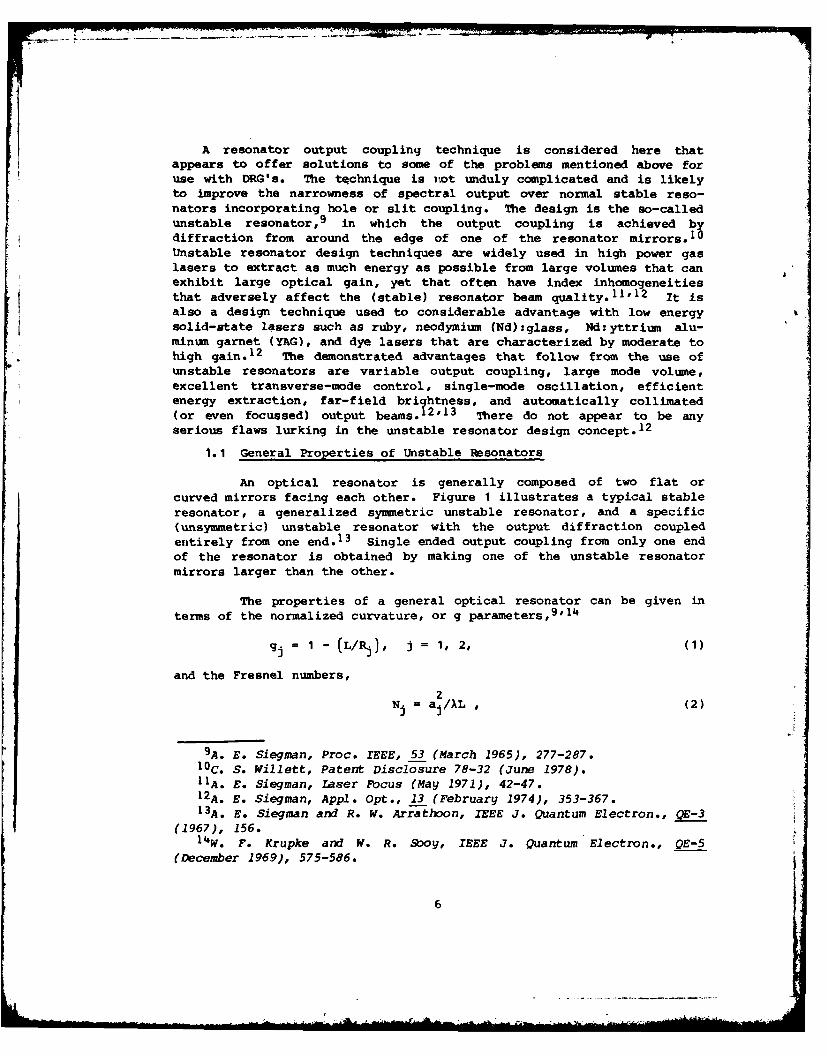
An optical resonator is generally composed of two flat orcurved mirrors facing each other. Figure I illustrates a typical stableresonator, a generalized symmetric unstable resonator, and a specific(unsymmetric) unstable resonator with the output diffraction coupledentirely from one end.1 3 Single ended output coupling from only one endof the resonator is obtained by making one of the unstable resonatormirrors larger than the other.
The properties of a general optical resonator can be given interms of the normalized curvature, or g parameters,
9,'1
= 1 - (L/ :i = 1, 2, (1)
and the Fresnel numbers,
2Nj = aj/XL , (2)
9A. E. Siegman, Proc. IEEE, 53 (March 1965), 277-287.10C. S. Willett, Patent Disclosure 78-32 (June 1978).11A. E. Siegman, Laser Focus (May 1971), 42-47.12A. E. Siegman, Appl. Opt., 13 (February 1974), 353-367.13A. E. Siegman and R. W. Arrathoon, IEEE J. Quantum Electron., QE-3
(1967), 156.14W. F. Krupke and W. R. Sooy, IEEE J. Quantum Electron., QE-5
(December 1969), 575-586.
6
where L is the distance between the two mirrors, Rj is the radius ofcurvature of the jth mirror (defined as positive if the center of cur-vature lies toward the interior of the resonator), and 2a is the diam-eter.of the jth mirror. With these definitions, the parameter space oftwo mirrors, g1 and g2, can be divided into stable and unstable regionsas shown in figure 2, where the stable (shaded) region is defined by theanalytic condition j
0 < glg 2 1 < 1 * (3)
9 2 1 -L/R2L 3
STABLE
M ~~M21 PLANAR
CON FOCAL
1 2 3
g1 g 1 -1"RCONCENTRIC
LRSYMMETRIC UNSTABLE
9192
Figure 2. General opticalresonator (insert) and
uNSYMMETRIC UNSTABLE mode chart that summarizes
Figure 1. Examples of mode stability properties;typical stable and unstable resonators lieunstable resonators outside shaded regions(from A. E. Siegman and (from A. E. Siegman, Proc.R. W. Arrathoon, IEEE IEEE, 53 (March 1965), 278).J. Quantum Electron.,QE-3 (1967), 156).
There are two general types of unstable resonators, negativebranch and positive branch. Negative branch unstable resonators haveproducts of their g parameters
glg 2 < 0 * (4)
Positive branch unstable resonators have
g1g2 > 1 . (5)
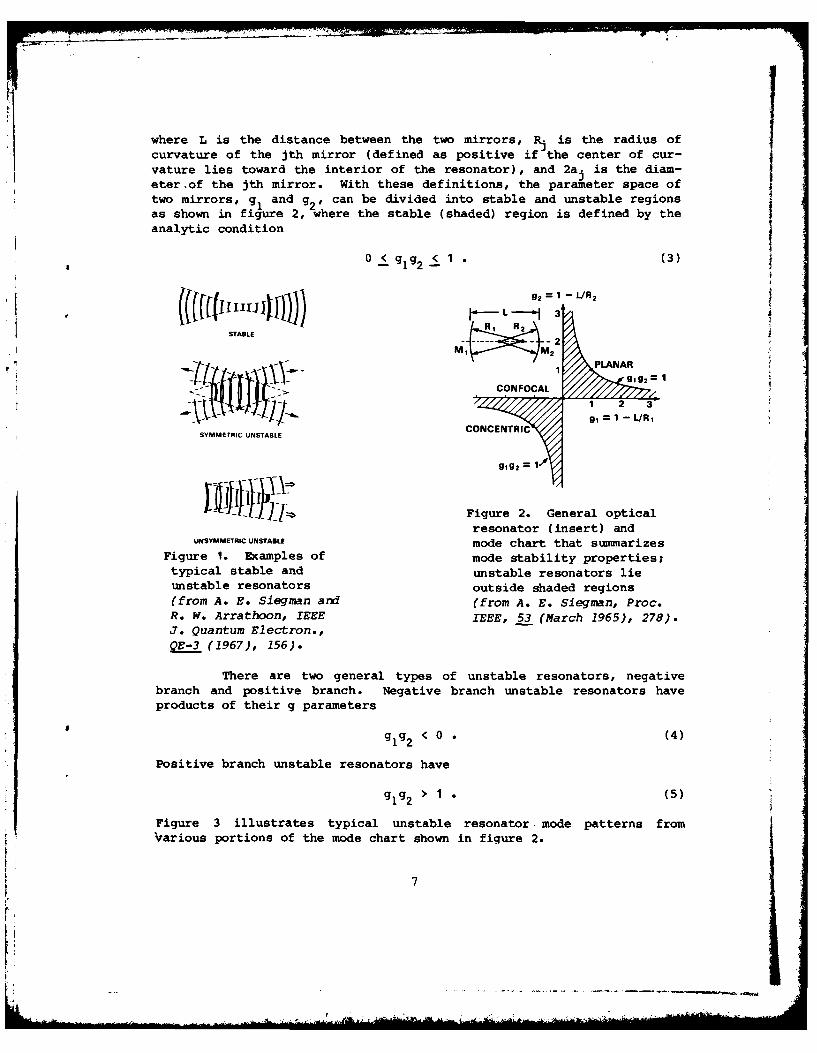
Figure 3 illustrates typical unstable resonator. mode patterns fromvarious portions of the mode chart shown in figure 2.
7
, M, g =
.-- P 2 I 1
R - 4 >M2 -
-P' M M>2 2 M
(g =0.5 g 2 =-0.5) (g =2g 2 f=
-1/ 8 )
Figure 3. Typical unstable modepatterns illustrating mode behaviorin different unstable regions ofmode chart (from A. E. Siegman,Proc. IEEE, 53 (March 1965), 280).
The most useful form of unstable resonator geometry for conven-tional lasers (not DRG's) is the so-called confocal or telescopicunstable resonator in an asymmetrical form. The two general types ofconfocal unstable resonator, are illustrated in figure 4. Both givecollimated beam outputs. The confocality condition requires
(Rj/L) + (R2/L) = 2
or
g = g2/(2g 2 - 1) (6)
The negative branch confocal configuration has significantpractical advantages in the form of more easily obtainable shorterradius mirrors and considerably easier mirror alignment tolerances. 14
However, because the internal focal point in the negative branch config-uration leads to difficulties with optical breakdown, 12 the positivebranch resonator is used most often with high energy gas laser systems.
4)
12A. E. Siegman, Appl. Opt., 13 (February 1974), 353-367.14 W. F. Krupke and W. R. Sooy, IEEE J. Quantum Electron., QE-5
(December 1969), 575-586.
8

in any final practical design of an unstable resonator for aDRG, it is envisioned that the output mirror, M , be deposited on alarger optical element through which the energy diffracted beyond theedge of M2 can be transmitted. Further, by a suitable combination ofradii of curvatures of the first and second surfaces of the outputelement, the output radiation can be suitably converged and coupled tooutside circuitry. It is further proposed that the output opticalelement provide a vacuum seal between the volume of the DRG in which theelectron beam interacts with the diffraction grating and any externalcircuitry or load (fig. 5).
L OUTPUT
M :> I MCONVERGINGM M2 / LENS
+R1 /2 +R 2/2 OUTPUT MIRROR
NEGATIVE BRANCH M2
M ij -R2.1M . :1
POSITIVE BRANCHMIRROR M1 DIFFRACTION
GRATING
Figure 4. Negative and Figure 5. Basic configuration ofpositive branch confocal unstable resonator for closed-offunstable resonators. diffraction radiation generator.
1.2 Diffraction Losses
The waves in an unstable resonator not only fill the mirrors ofthe resonator, but spread to become larger than the mirrors by amagnification factor that depends only on the resonator g parameters.The radiation that goes past the outer edges of the output mirror, whichwould normally be a loss, constitutes the output coupling from theresonator. This coupling depends only on the linear magnification, M,and can be calculated from basic geometric principles. It is inde-pendent of the mirror sizes, wavelength, and Fresnel number. The linearmagnification is equal to the ratio of the mirror diameters. It ispossible then to have relatively large diameter modes even in relativelyshort unstable resonators. Having them would be difficult with stableresonator configurations, which are usually long and narrow.
9
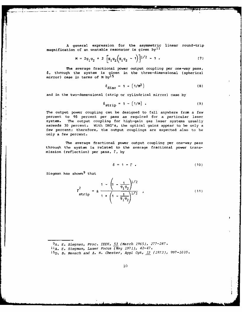
A general expression for the asymmetric linear round-tripmagnification of an unstable resonator is given by-1
M = 2g g2 + 2 [g1 g2 (glg 2 - 1)]1/2 - 1 (7)
The average fractional power output coupling per one-way pass,6, through the system is given in the three-dimensional (sphericalmirror) case in terms of M by
15
s = 1 - (1/M2) (8)
and in the two-demensional (strip or cylindrical mirror) case by
6 strip = 1 - (1/M) . (9)
The output power coupling can be designed to fall anywhere from a fewpercent to 95 percent per pass as required for a particular lasersystem. The output coupling for high-gain gas laser systems usuallyexceeds 30 percent. With DRG's, the optical gains appear to be only afew percent; therefore, the output couplings are expected also to beonly a few percent.
The average fractional power output coupling per one-way pass
through the system is related to the average fractional power trans-mission (reflection) per pass, r, by
6 =1 - r (10)
Siegman has shown9 that
( 1 1/2r =± " ,(11)
strip 1 + 1 1/g 2
9A. E. Siegman, Proc. IEEE, 53 (March 1965), 277-287.11A. E. Siegman, Laser Focus (May 1971), 42-47.15D. B. Rensch and A. N. Chester, Appl Opt, 12 (1973), 997-1010.
10
where rstri_ is the average power transmission per pass for strip
(cylindrical- mirrors, the upper (+) sign is valid for g values in the
first and third quadrants of the mode chart, and the lower (-) sign is
valid for the second and fourth quadrants.
For circular (disc) mirrors,
2rdisc r rstrip . (12)
Since the g parameters do not involve the sizes or the shapes of the
mirrors, rstrip and rdisc are independent of these parameters and depend
only on the mirror separation, L, and the radii of curvature, R and R2
1.3 Confocal Resonators
Figure 4 shows the geometry of negative branch and positive
branch confocal resonators. For the negative branch confocal unstableresonator,
R = 2ML/(M + 1)
R2 = 2L/(M + 1)
For the positive branch confocal unstable resonator,
R, = 2ML/(M - 1)
R2 = -2L/(M - 1)
Each radius of curvature is directly proportional to the separation ofthe mirrors for both negative and positive branch confocal unstableresonators and is independent of the mirror sizes.
2. OPTIMUM OUTPUT COUPLING FOR DIFFRACTION RADIATION GENERATOR
To achieve maximum output power from a .DRG, the output coupling mustbe matched to the gain of the DRG at its operating point.
Resonator losses in DRG's are primarily (1) ohmic losses at themirrors, (2) diffraction and reflection losses, (3) scattering losses atthe mirrors, or (4) output coupling losses.
16
16D. E. Wortman and R. P. Leavitt, Research Study on Near Millimeter
Wave Oratrons, Harry Diamond Laboratories hDL-SR-80-4 (July 1980).
11

All indications i are that losses in DRG's are dominated by ohmiclosses and that these are primarily due to the presence of the reflec-tion grating.
Although measurements of the gain of DRG's from which one might beable to calculate optimum output couplings are not available from theliterature, actual transmission coefficients of DRG's operating withquasi-optical output coupling have been published. 6 These transmissioncoefficients are of the order of a few percent and, therefore, are theorder of the output couplings that can be tolerated in a DRG. A fewpercent is assumed in this report to be typical of the output couplingof a DRG (operating at a wavelength of 4 mm).
3. UNSTABLE RESONATOR DESIGN FOR DIFFRACTION RADIATION GENERATOR
Values have been calculated for mirror curvatures R and R fornegative and positive branch unstable resonators (using disc orspherical mirrors) for output couplings that range from 3 to a few tensof percent. Figure 6 gives values of output coupling for values of Rfor mirror separations of 1, 2, 4, and 6 cm. A mirror separation ofcm is typical for a stable resonator DRG and is probably appropriate forany unstable resonator DRG operating at wavelengths of a fewmillimeters. Figure 7 shows the variation of output coupling withmirror radius R 1 for an unstable confocal resonator mirror separation of1 cm. Since R is directly proportional to the mirror separation, RIIcan be found from figure 7 for any value of mirror separation if thevalue of R given in the figure is multiplied by L in centimeters.(This is why a 1-cm mirror separation is used in calculating data givenin the figure, rather than a 2-cm separation, which is probablyappropriate for a DRG operating in the near-millimeter region.)
As seen in figure 6, the variation of output coupling of the nega-tive branch confocal unstable resonator is a very strong function of themirror radius R (and R 2). The output coupling changes (for a mirrorseparation of 2 cm) from 3 to 10 percent for a change in mirror radiusof curvature (R ) of 0.03 cm. At the lowest output couplings shown infigure 6, a mirror radius change of 0.01 cm can change output couplingfrom 3 to 5 percent. In view of this extreme sensitivity of the outputcoupling to mirror radius, which would be hard to manufacture to therequired accuracy for a particular output coupling, the negative branchconfocal resonator appears unsuited for use with DRG's.
iV. P. Shestopalov, Diffraction Electronics, Khar'kov (1976);translation by U.S. Joint Publications Research Service (April 1978);U.S. Army Foreign Science and Technology Center Document 923-77.
61. M. Balakliskii, I. D. Revin,B. K. Skrynnik, A. S. Sysoev, 0. A.Tret'yakov, and V. P. Shestopalov, Izv. Vyssh. Uchebn. Zaved. Radiofiz.,16 (February 1973), 235-243.
12

60 R 1.23 cm 2.45 cm 4.9 cm
7.02 cm
30 - 1.089 2.18 4.36 6.53
20 - 1.056 2.11 4.22 6.33e/10 1.026 2.05 4.11 6.16
CJ
2--.04 4.06 6.09C. 5 1.013 2.03 405 6.08
0
3 1.008 2.02 4.03 6.05L 1= cm L =2cm L =4cm L =6cm
R, R2 NOTE: R1 + R2 =2L.
S I I I I I I I I
0 1 2 3 4 5 6 7
MIRROR RADIUS (cm)
Figure 6. Variation of output coupling of diffractionradiation generator with mirror radius (RI) ofnegative branch confocal unstable resonator.
Unlike the behavior of the negative branch confocal unstable reso-nator, the variation of output coupling of a positive branch confocalunstable resonator is not a sensitive function of the mirror radius.This insensitivity is particularly so at the lowest output couplings.For a mirror separation of I cm and an output coupling of 3 percent, amirror curvature of 132 cm is required. (Hence, for a mirror separationof 2 cm, a mirror curvature of 264 cm is required.) For a 4-percentoutput coupling and L = 2 cm, R is approximately 198 cm. Mirrors ofthis curvature with a specified tolerance for a particular output
coupling are no problem to manufacture.
The presence of one of the essential elements, the planar or stripdiffraction grating in a DRG, limits the construction of resonators. Upto now, the most successful designs have used a single surface cylin-drical mirror as a lower (non-output) mirror along whose generatrix the
13

axis of the grating is situated (fig. 8). The upper mirror, throughwhich there is some form of output coupling (usually hole or slitcoupling), completes the cavity. To spread out the cavity mode alongthe length of the grating, the upper mirrors have incorporated compoundor multiple-radii spherical surfaces.1 '1 7 In all DRG's, in the choiceof (stable) resonators, the aim is to obtain two things: (1) a high-Qcavity with as extensive a cavity mode over the diffraction grating aspossible and (2) a region of high electric field strength localized overthe surface of the grating.
20
DISC MIRRORS
Figure 7. Variation of
10 M, 2 output coupling ofM, Ediffraction radiation
generator with mirrorradius (Ri) of positive
WHERE R, IS NEGATIVE branch confocalZ
unstable resonator.
0
TYPIA OUTPUT COUPLING OF OR"
0
1i I I I I I I20 40 60 80 100 120 140
MIRROR RADIUS R1 In) FOR L OF 1 C.
Figure 8. Schematic COMPOUND SURFACE
PAIRED CYLINDRICALdiagram of diffraction MIRROR
radiation generator(from V. K. Korneenkov 4 DIFF
-CTIO G
and V. P. Shestopalov, I N G-- DIFLESURFACE
Radio Physics and CYLINDRICAL MIRROR
Quantum Electron, 20(1977), 88).
IV. P. Shestopalov, Diffraction Electronics, Khar'kov (1976);translation by U.S. Joint Publications Research Service (April 1978);U.S. Army Foreign Science and Technology Center Document 923-77.1 7 V. K. Korneenkov and V. P. Shestopalov, Radiophys. QuantumElectron., 20 (1977), 87-90.
14
-I .. .... .
, I-. : .. ] . . .
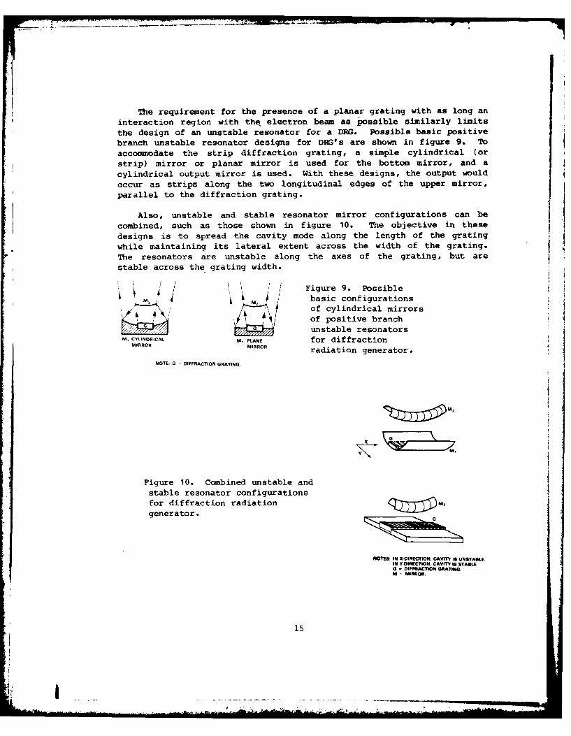
The requirement for the presence of a planar grating with as long aninteraction region with the electron beam as possible similarly limits
the design of an unstable resonator for a DRG. Possible basic positivebranch unstable resonator designs for DRG's are shown in figure 9. Toaccommodate the strip diffraction grating, a simple cylindrical (orstrip) mirror or planar mirror is used for the bottom mirror, and acylindrical output mirror is used. With these designs, the output wouldoccur as strips along the two longitudinal edges of the upper mirror,parallel to the diffraction grating.
Also, unstable and stable resonator mirror configurations can becombined, such as those shown in figure 10. The objective in thesedesigns is to spread the cavity mode along the length of the gratingwhile maintaining its lateral extent across the width of the grating.The resonators are unstable along the axes of the grating, but arestable across the grating width.
~ 1 /Figure 9. Possiblebasic configurationsof cylindrical mirrors
of positive branchunstable resonators
M, CYLINDRICAL M, PLANE for diffraction
MIRROR MIRROR radiation generator.NOTE: G - DIFFRACTION GRATING.
Figure 10. Combined unstable and
stable resonator configurationsfor diffraction radiationgenerator.
NOTES: IN X-OIRECTION, CAVITY IS UNSTABLE.
IN Y-OIREC1nON, CAVITY IS STABLE0 = DIFFRACTION GRATNG.
M MIRROR.
15
-m
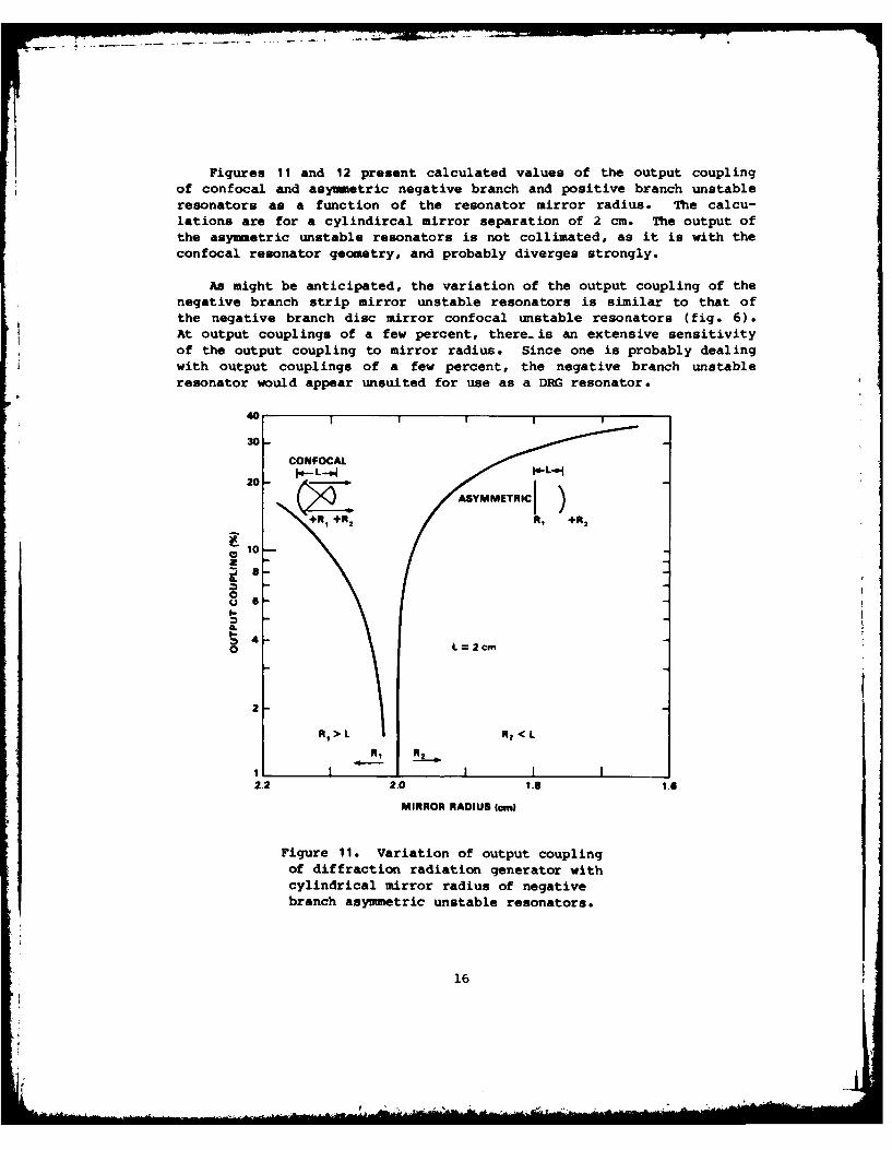
Figures 11 and 12 present calculated values of the output couplingof confocal and asymmetric negative branch and positive branch unstableresonators as a function of the resonator mirror radius. The calcu-lations are for a cylindircal mirror separation of 2 cm. The output ofthe asymmetric unstable resonators is not collimated, as it is with theconfocal resonator geometry, and probably diverges strongly.
As might be anticipated, the variation of the output coupling of thenegative branch strip mirror unstable resonators is similar to that ofthe negative branch disc mirror confocal unstable resonators (fig. 6).At output couplings of a few percent, there-is an extensive sensitivityof the output coupling to mirror radius. Since one is probably dealingwith output couplings of a few percent, the negative branch unstableresonator would appear unsuited for use as a DRG resonator.
40
30-
CONFOCAL
20- /ASYMMETRIC+R1 +R 2 R, +R 2
10-
A..0
-
0 L=2cm
R 2 <L
R, R21 I I I2.2 2.0 1.3 1.e
MIRROR RADIUS 4cm)
Figure 11. Variation of output couplingof diffraction radiation generator withcylindrical mirror radius of negativebranch asymmetric unstable resonators.
16
Fo
40-
20-" ASYMMETRIC M2R
o
2R2
MIRRCONFOCAL
0
/TYPICALUPTCUPIGO DRGS
MIRROR RADIUS (cm) R2 ASYMMETRIC, R1 CONFOCAL
Figure 12. Variation of output couplingof diffraction radiation generator with
cylindrical mirror radius of positive branchasymmetric unstable resonators.
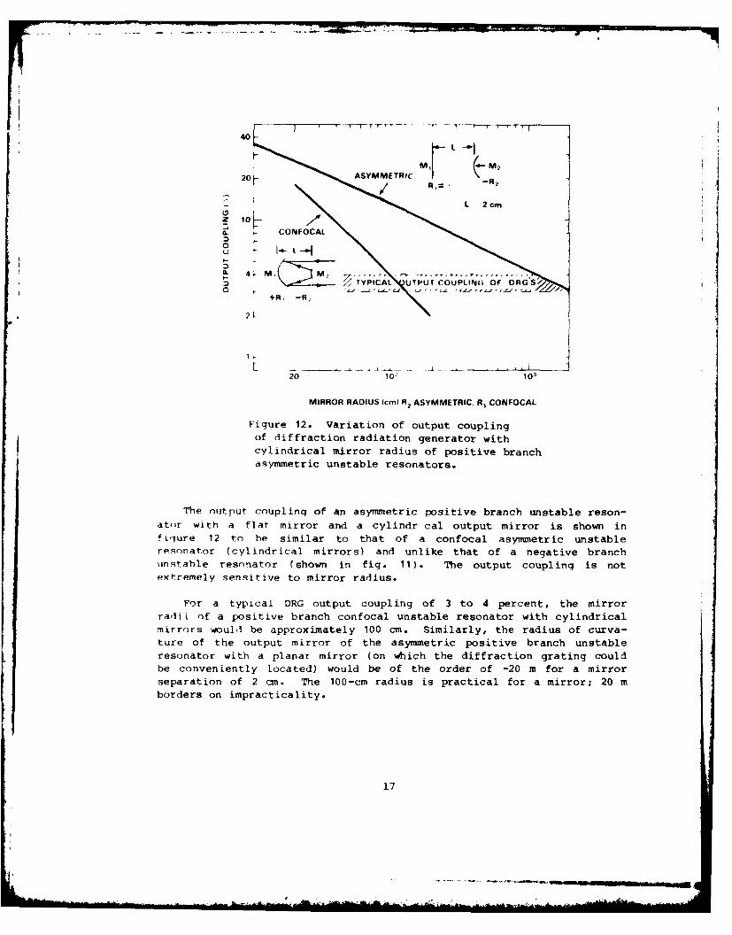
The output coupling of an asymmetric positive branch unstable reson-
ator with a flat mirror and a cylindr cal output mirror is shown infirgure 12 to he similar to that of a confocal asymmetric unstableresonator (cylindrical mirrors) and unlike that of a negative branchunstable resonator (shown in fig. 11). The output coupling is notextremely sensitive to mirror radius.
For a typical DRG output coupling of 3 to 4 percent, the mirrorradii of a positive branch confocal unstable resonator with cylindricalmirrors would be approximately 100 cm. Similarly, the radius of curva-ture of the output mirror of the asymmetric positive branch unstableresonator with a planar mirror (on which the diffraction grating couldbe conveniently located) would be of the order of -20 m for a mirrorseparation of 2 cm. The 100-cm radius is practical for a mirror; 20 mborders on impracticality.
17
The output of these positive branch unstable resonators wouldconsist of two strips parallel to the generatrix of the cylindricalmirror surfaces. If it were found to be advantageous to use the walk-off properties of the unstable resonator to extend the cavity mode alongthe length of the grating (rather than across it as in fig. 9), theresonator configurations shown in figure 10 could possibly be used. Inthe direction across the grating, the resonator could be made to be
stable, while along the grating the resonator could be unstable. Theoutput would consist of two blobs at each end of the unstable resonatoralong the axis of the diffraction grating.
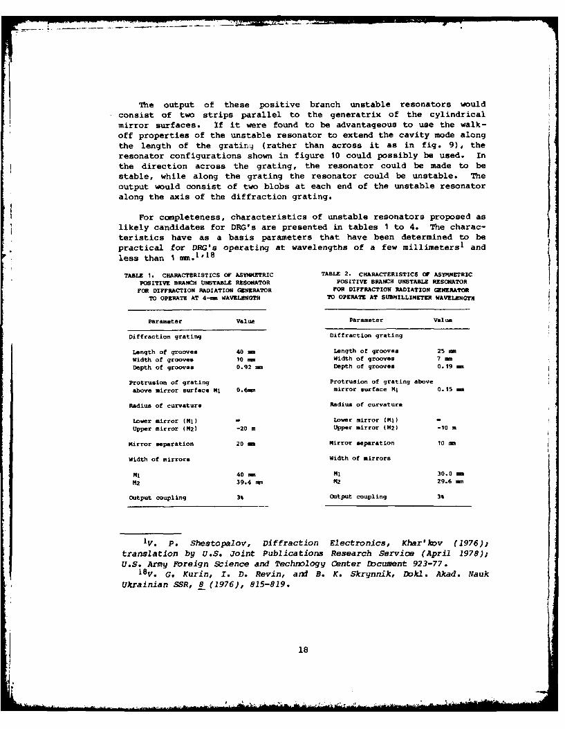
For completeness, characteristics of unstable resonators proposed as
likely candidates for DRG's are presented in tables I to 4. The charac-teristics have as a basis parameters that have been determined to be
practical for DRG's operating at wavelengths of a few millimeters1 andless than 1
S.I 8
TABLE 1. CHARACTERISTICS OF ASYMMETRIC TABLE 2. CHARACTERISTICS OF ASYMMETRICPOSITIVE BRANCH UNSTABLE RESONATOR POSITIVE BRANCH UNSTABLE RESONATOR
FOR DIFFRACTION RADIATION GENERATOR FOR DIFFRACTION RADIATION GENERATORTO OPERATE AT 4-mm WAVELENGTH TO OPERATE AT SUBDILLIMETER WAVELENGTH
Parameter Value Parameter Value
Diffraction grating Diffraction grating
Length of grooves 40 mm Length of grooves 25 eWidth of grooves 10 mm Width of grooves 7 m
Depth of grooves 0.92 m Depth of grooves 0.19 -
Protrusion of grating Protrusion of grating above
above mirror surface NJ 0.6mm mirror surface NJ 0.15 mm
Radius of curvature Radius of curvature
Lower mirror (Ni) ower mirror (NJ) -
Upper mirror (M2) -20 m Upper mirror (M2) -10 m
Mirror separation 20 m Mirror separation 10 m
Width of mirrors Width of mirrors
NJ 40 m NJ 30.0 -m
M2 39.4 mm M2 29.6 mm
Output coupling 3% Output coupling 3%
IV. P. Shestopalov, Diffraction Electronics, Khar'Ihv (1976);translation by U.S. Joint Publications Research Service (April 1978);U.S. Army Foreign Science and Technology Center Document 923-77.
8V. G. Kurin, I. D. Revin, and B. K. Skrynnik, Dokl. Akad. Nauk
Ukrainian SSR, 8 (1976), 815-819.
II
18
. . . . . . .. .-
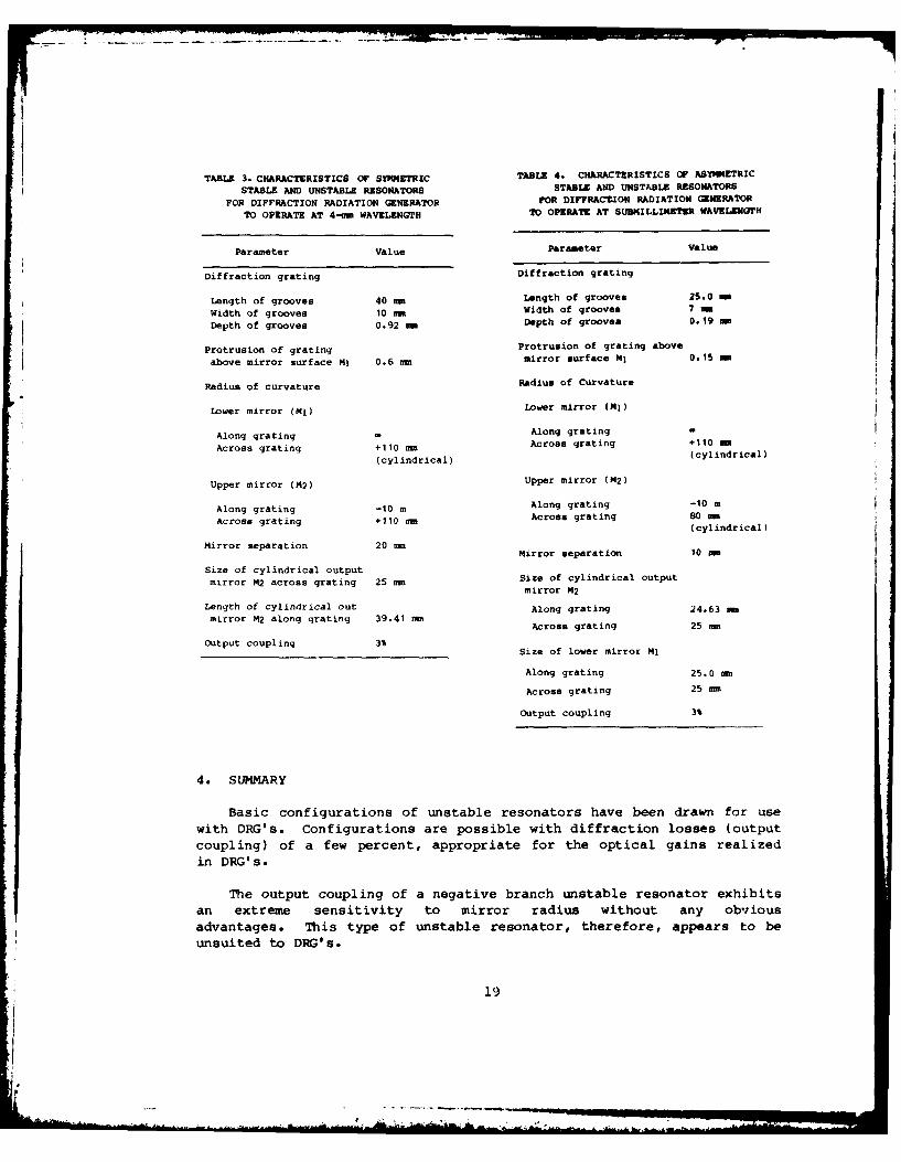
TABLE 3. CHARACTERISTICS OF SYMMETRIC TABLE 4. CHARACTERISTICS OF ASYMMETRIC
STABLE AND UNSTABLE RESONATORS STABLE AND UNSTABLE RESONATORS
FOR DIFFRACTION RADIATION GENERATOR FOR DIFFRACT.ION RADIATION GENERATOR
TO OPERATE AT 4-mm WAVELENGTH TO OPERATE AT SUBMILLII4TER WAVELENGTH
Parameter Value Parameter Value
Diffraction grating Diffraction grating
Length of grooves 40 mm Length of grooves 25.0 -
Width of grooves 10 mm Width of grooves 7 m
Depth of grooves 0.92 am Depth of grooves 0.19 -
Protrusion of grating Protrusion of grating above
above mirror surface M! 0.6 n mirror surface MI 0.15 -
Radius of curvature Radius of Curvature
Lower mirror (M) Lower mirror (MI)
Along grating - Along grating -
Across grating +110 mm Across grating +110 -
(cylindrical) (cylindrical)
Upper mirror (M2) Upper mirror (M2)
Along grating -10 m Along grating -10 m
Across grating +110 mm Across grating 80 mm(cylindrical)
Mirror separation 20 mmMirror separation 10 an
Size of cylindrical output
mirror M2 across grating 25 mm Size of cylindrical outputmirror M2
Length of cylindrical out Along grating 24.63 an
mirror M2 along grating 39.41 anAcross grating 25 aIn
Output coupling 3%Size of lower mirror Mj
Along grating 25.0 an
Across grating 25 mm
Output coupling 3%
4. SUMMARY
Basic configurations of unstable resonators have been drawn for use
with DRG's. Configurations are possible with diffraction losses (output
coupling) of a few percent, appropriate for the optical gains realized
in DRG's.
The output coupling of a negative branch unstable resonator exhibits
an extreme sensitivity to mirror radius without any obvious
advantages. This type of unstable resonator, therefore, appears to be
unsuited to DRG's.
19
1, i

The positive branch unstable resonator configuration does notexhibit any extreme sensitivity to mirror radius and appears suitablefor use with DRG's. Furthermore, the radii of curvature of the mirrorsneeded to give output couplings of a few percent are practicable.
There is one reservation: DRG's require both high-Q cavities andhigh electric field strengths (E2's) localized in the interaction regionof the ribbon-like electron beam and the grating. Whereas it has beenshown here that unstable resonator configurations for DRG's with high-Qcavities are possible, it is not known whether they have spatial E2
distributions that allow for a good electron beam and diffractiongrating interaction region. Their actual characteristics and suit-ability as resonators for DRG's, however, could presumably be determinedin experiments similar to those carried out on stable DRGresonators. 1 019
IV. P. Shestopalov, Diffraction Electronics, Khar'kov (1976);translation by U.S. Joint Publications Research Service (April 1978);U.S. Army Foreign Science and Technology Center Document 923-77.
19 A. A. Verty, V. M. Mokry, E. E. Moroz, N. A. Popenko, A. S. Soroka,and V. I. Shkodin, Izv. Vyssh. Uchebn. Zaved. Radiofiz., 24 (1979), 641-643.
20
_AL .
LITERATURE CITED
(1) V. P. Shestopalov, Diffraction Electronics, Khar'kov (1976);
translation by U.S. Joint Publications Research Service (April
1978); U.S. Army Foreign Science and Technology Center Document
(2) F. S. Rusin and G. D. Bogomolov, Proc. IEEE, 57 (April 1978), 720.
(3) K. Mizuno, IEEE Trans. Electron Devices, 20 (August 1973), 749-752.
(4) F. S. Rusin and Go D. Bogomolov, JETP Letters, 4 (1968), 160.
(5) V. P. Shestopalov, 1. M. Balakletsky, and 0. A. Tret'yakov,Electrotech., 12 (1972), 50.
(6) 1. M. Balakliskii, I. Do Revin, B. K. Skrynnik, A. S. Sysoev, 0.A. Tret'yakov, and V. P. Shestopalov, Izv. Vyssh. Uchebn. Zaved.Radiofiz., 16 (February 1973), 235-243.
(7) V. Go Kurin, B. K. Skrynnik, and V. P. Shestopalov, Izv. Vyssho
Uchebn. Zaved. Radiofiz., 19 (January 1976), 128-134.
(8) G. D. Bogomolov and F. S. Rusin, Radio Eng. Electron. Phys., 15(1970), 727-728.
(9) A. E. Siegman, Proc. IEEE, 53 (March 1965), 277-287.
(10) C. S. Willett, Patent Disclosure 78-32 (June 1978).
(11) A. E. Sieginan, Laser Focus (May 1971), 42-47.
(12) A. E. Siegman, Appl. Opt., 13 (February 1974), 353-367.
(13) A. E. Siegman and'R. W. Arrathoon, IEEE J. Quantum Electron., QE-3
(1967), 156.
(14) W. F. Krupke and W. R. Sooy, IEEE J. Quantum Electron., QE-5(December 1969), 575-586.
(15) Do B. Rensch and A. N. Chester, Appl. Opt. 12 (1973), 997-1010.
(16) D. E. Wortman and R. P. Leavitt, Research Study on Near Millimeter
Wave Oratrons, Harry Diamond Laboratories HDL-SR-80-4 (July 1980).
(17) V. K. Korneenkov and V. P. Shestopalov, Radiophys. Quantum
Electron., 20 (1977), 87-90.
21
LITERATURE CITED (Cont' d)
(18) V. G. Kurin, I. D. Revin, and B. K. Skrynnik, Dokl. Akad. NaukUkrainian SSR, 8 (1976), 815-819.
(19) A. A. Verty, V. M. Mokry, E. E. Moroz, N. A. Popenko, A. S.Soroka, and V. I. Shkodin, Izv. Vyssh. Uchebn. Zaved. Radiofiz.,24 (1979), 641-643.
22
DISTRIBUTION
ADMINISTRATOR COMMANDERDEFENSE TECHNICAL INFORMATION CENTER US AIR FORCE ROME AIRATTN DTIC-DDA (12 COPIES) DEVELOPMENT CENTER
CAMERON STATION ATTN RADC/ETEN, E. ALTSHULERALEXANDRIA, VA 22314 L. G. HANSCOMB FIELD
BEDFORD, MA 01730COMMANDERUS ARMY MATERIEL DEVELOPMENT & COMMANDERREADINESS COMMAND US ARMY ATMOSPHERICATTN DRCDE, DIR FOR DEVEL & ENGR SCIENCES LABORATORYATTN DRCDM-ST ATTN H. RACHELLEATTN DRCBSI, P. DICKERSON ATTN DRSEL-BL-AS-P, K. WHITE5001 EISENHOWER AVENUE ATTN DRSEL-BL, LIBRARYALEXANDRIA, VA 22333 WHITE SANDS MISSILE RANGE, NE4 88002
COMMANDER COMMANDERUS ARMY ARMAMENT MATERIEL US ARMY FOREIGN SCIENCE ANDREADINESS COMMAND TECHNOLOGY CENTER
ATTN DRSAR-LEP-L, TECHNICAL LIBRARY 220 SEVENTH STREET, NEROCK ISLAND, IL 61299 ATTN DRXST-SD, 0. R. HARRIS
CHARLOTTESVILLE, VA 22901COMMANDERUS ARMY MISSILE & MUNITIONS COMMANDERCENTER & SCHOOL US ARMY MISSILE COMMANDATTN ATSK-CTD-F ATTN DRSMI-REO, G. EIMONSREDSTONE ARSENAL, AL 35809 ATTN DRDMI-TRO, W. L. GAMBLE
ATTN DRDMI-TRO, B. D. GUENTHERDIRECTOR ATTN DRDMI-TR, R. L. HARTMANUS ARMY MATERIEL SYSTEMS ANALYSIS ATTN DRDMI-TB, REDSTONE SCIENCEACTIVITY INFORMATION CENTERATTN DRXSY-MP REDSTONE ARSENAL, AL 35809
ABERDEEN PROVING GROUND, MD 21005
COMMANDERDIRECTOR US ARMY NIGHT VISION & ELECTRO-OPTICSUS ARMY BALLISTIC RESEARCH LABORATORY LABORATORYATTN DRDAR-TSB-S (STINFO) ATTN W. EALYATTN DRXBR, DIRECTOR ATTN DELNV-VI, J. R. MOULTONATTN DRXBR-TB, F. J. ALLEN ATTN DELNV-II, R. SHURTZATTN DRDAR-BLB, R. MCGEE ATTN LIBRARYATTN DRDAR-BL, H. REED ATTN DR. R. C. BUSER
ABERDEEN PROVING GROUND, MD 21005 ATTN DELNV-L, R. RHODEFT BELVOIR, VA 22060
TELEDYNE BROWN ENGINEERINGATTN MS-44, MELVIN L. PRICE COMMANDER
CUMMINGS RESEARCH PARK US ARMY RESEARCH OFFICEHUNTSVILLE, AL 35807 ATTN DRXDO-PH, R. LONTZ
ATTN DRXDO-PH, C. BOGHOSIANUS ARMY ELECTRONICS TECHNOLOGY ATTN DR. J. StTTLEAND DEVICES LABORATORY RESEARCH TRIANGLE PAR,ATTN DELET-DO DURHAM, MC 27709ATTN DELET-B, I. REINGOLDATTN DELET-I, H. JACOBS COMMANDERATTN DELET-I, A. KERECMAN NAVAL RESEARCH LABORATORY
FORT MONMOUTH, NJ 07703 ATTN V. L. GRANATSTEINATTN CODE 7111, J. P. HOLLINGER
COWANDER ATTN CODE 7122. 1, K. SHIVANANDANUS AIR FORCE GEOPHYSICAL LAB ATTN CODE 7110, B. YAPLEEATTN S. A. CLOUGH ATTN L. YOUNGL. G. HANSCOMB FIELD WASHINGTON, DC 20375BEDFORD, MA 01731
- 23
DISTRIBUTION (Cont 'd)
COMMANDER INSTITUTE FOR DEFENSE ANLAYSESNAVAL SURFACE WEAPONS CENTER ATTN V. J. CORCORAN
ATTN F-34, J. J. TETI, JR. 400 ARMY-NAVY DRIVEDAHLGREN, VA 22448 ARLINGTON, VA 22202
COMMANDER THE IVAN A. GETTING LABNAVAL SURFACE WEAPONS CENTER THE AEROSPACE CORPORATION
ATTN R-42, N. GRIFF ATTN E. J. DANIELEWICZ, JR.ATTN R-43, A. KRALL ATTN T. S. HARTWICKATTN F-46, R. E. JENSEN ATTN D. T. HODGES
WHITE OAK, MD 20910 P.O. BOX 92957
LOS ANGELES, CA 90009COMMANDERBALLISTIC MISSILE DEFENSE AGENCY LITTON INDUSTRIES, INC.ADVANCED TECHNOLOGY CENTER ELECTRON TUBE DIVISION
ATTN BMD-ATC-D, C. JOHNSON ATTN P. BAHRP.O. BOX 1500 ATTN J, HULLHUNTSVILLE, AL 35807 ATTN J. MUNGER
1035 WESTMINISTER DRIVEDEFENSE ADVANCED RESEARCH PROJECTS AGENCY WILLIAMSPORT, PA 17701ATTN TTO, J. TEGNELIAATTN STO, S. ZAKANYCZ MASS INSTITUTE OF TECHNOLOGY
1400 WILSON BLVD FRANCIS BITTER NATIONALARLINGTON, VA 22209 MAGNET LABORATORY
ATTN K. J. BUTTONNASA/GODDARD SPACE FLIGHT CENTER ATTN R. J. TEMKIN
ATTN CODE 723, N. MCAVOY 170 ALBANY STREETGREENBELT, MD 20771 CAMBRIDGE, MA 02139
NATIONAL BUREAU OF STANDARDS MASS INSTITUTE OF TECHNOLOGYATTN K. M. EVENSON LINCOLN LABORATORYATTN R. PHELAN ATTN C. BLAKEBOULDER, CO 80302 ATTN H. R. FETTERMAN
ATTN D. TEMMEEMORY UNIVERSITY--PHYSICS DEPARTMENT P.O. BOX 73
ATTN S. PERKOWITZ LEXINGTON, MA 02173ATLANTA, GA 30322
NORTHROP CORPORT ION
ENVIRONMENTAL RESEARCH DEFENSE SYSTEMS DIVISIONINSTITUTE OF MICHIGAN ELECTRON TUBE SECTIONATTN M. BAIR ATTN G. DOEHLERATTN G. H. SUITS ATTN 0. DOEHLER
P.O. BOX 618 ATTN R. ESPINOSAANN ARBOR, MI 48107 ATTN R. MOATES
DES PLAINES, IL 60018FORD-AERONUTRONIC
ATTN D. E. BURCH R&D ASSOCIATESFORD ROAD ATTN DR. G. GORDONNEWPORT, CA 92663 P.O. BOX 9695
MARINA DEL REY, CA 90291GEORGIA INSTITUTE OF TECHNOLOGYENGINEERING EXPERIMENT STATION RAYTHEON COMPANY
ATTN J. J. GALLAGHER MICROWAVE AND POWER TUBEATTN J. WILTSE DIVISION
ATLANTA, GA 30332 ATTN L. CLAMPITTATTN R. HARPER
HONEYWELL CORPORATE RESEARCH CENTER FOUNDRY AVENUEATTN P. W. KRUSE WALTHAM, MA 02154
10701 LYNDALE AVE, SOUTHBLOOMINGTON, MN 55420
24
DISTRIBUTION (Cont'd)
UNIVERSITY OF ILLINOISDEPARTMENT OF ELECTRICAL
ENGINEERING--EERL-200
ATTN P. D. COLEMANATTN T. A. DETEMPLE
URBANA, IL 61801
VARIAN ASSOCIATESPALO ALTO MICROWAVE TUBE DIVISIONATTN H. JORYATTN A. KARPATTN E. LIEN
611 HANSEN WAYPALO ALTO, CA 94303
US ARMY ELECTRONICS RESEARCH& DEVELOPMENT COMMANDATTN TECHNICAL DIRECTOR, DRDEL-CTATTN J. SCALES, DRDEL-CM
ATTN C. S. WILLETT, DRDEL-CM (10 COPIES)ATTN B. ZARWYN, DRDEL-AP-OA
HARRY DIAMOND LABORATORIESATTN CO/TD/TSO/DIVISION DIRECTORSATTN RECORD COPY, 81200ATTN HDL LIBRARY, 81100 (3 COPIES)ATTN HDL LIBRARY, 81100 (WOODBRIDGE)ATTN CHAIRMAN, EDITORIAL COMMITTEEATTN TECHNICAL REPORTS BRANCH, 81300ATTN CHAIRMAN, EDITORIAL COMMITTEEATTN H. GERLACH, 11100
ATTN J. NEMARICH, 13300ATTN R. LEAVITT, 13200ATTN C. MORRISON, 13200
ATTN J. SATTLER, 13200ATTN G. SIMONIS, 13200ATTN M. TOBIN, 13200ATTN T. WORCHESKY, 13200ATTN D. WORTMAN, 13200ATTN E. BROWN, 15400ATTN S. TJLPA, 15400ATTN H. BRANDT, 22300
ATTN A. BROMBORSKY, 22300ATTN J. SILVERSTEIN, 22900ATTN CHIEF, 13500ATTN K. SANN, 15000
25


![Broadband resonator-waveguide coupling for efficient ... · the resonator dispersion profile for octave bandwidth [6,7], or even super-octave bandwidth [8], has been widely reported,](https://img.pdfslide.us/doc/110x75/611e88f7bfe3b84497714dcf/broadband-resonator-waveguide-coupling-for-efficient-the-resonator-dispersion.jpg)