Embed Size (px)
Citation preview

10 in. COMPOUND MITER SAWDOUBLE INSULATED
Model Nos.315.212340315.242340
OPERATOR'S MANUAL
WARNING: To reduce the risk of injury, the user must read and understand the operator’s manual before using this product.
Customer Help Line: 1-800-932-3188
Sears, Roebuck and Co., 3333 Beverly Rd., Hoffman Estates, IL 60179 USAVisit the Craftsman web page: www.sears.com/craftsman
983000-517 6-04
Save this manual for future reference
2 3
TABLE OF CONTENTS
n Warranty ............................................................................................................................................................................2
n Introduction .......................................................................................................................................................................2
n General Safety Rules..................................................................................................................................................... 3-4
n Specific Safety Rules..................................................................................................................................................... 4-5
n Symbols......................................................................................................................................................................... 6-7
n Electrical ............................................................................................................................................................................8
n Glossary of Terms..............................................................................................................................................................9
n Features..................................................................................................................................................................... 10-12
n Tools Needed ................................................................................................................................................................. 13
n Loose Parts .................................................................................................................................................................... 14
n Assembly ................................................................................................................................................................... 15-24
n Operation................................................................................................................................................................... 24-30
n Adjustments .............................................................................................................................................................. 31-32
n Maintenance.............................................................................................................................................................. 32-33
n Exploded View........................................................................................................................................................... 34-41
n Parts Ordering/Service ...................................................................................................................................... Back Page
ONE YEAR FULL WARRANTY ON CRAFTSMAN TOOL
If this Craftsman tool fails due to a defect in material or workmanship within one year from the date of purchase, CONTACT THE NEAREST SEARS PARTS & REPAIR CENTER at 1-800-4-MY-HOME® and Sears will repair it, free of charge. This warranty applies only while this product is in the United States.
If this tool is used for commercial or rental purposes, this warranty will apply for only ninety days from the date of purchase.
This warranty gives you specific legal rights, and you may also have other rights which vary from state to state.
Sears, Roebuck and Co., Dept. 817WA, Hoffman Estates, IL 60179
INTRODUCTION
WARRANTY
This tool has many features for making its use more pleasant and enjoyable. Safety, performance, and dependability have been given top priority in the design of this product making it easy to maintain and operate.
2 3
GENERAL SAFETY RULES
WARNING: Read and understand all instruc-tions. Failure to follow all instructions listed below, may result in electric shock, fire and/or serious personal injury.
READ ALL INSTRUCTIONSn KNOW YOUR POWER TOOL. Read the operator's
manual carefully. Learn the saw's applications andlimitations as well as the specific potential hazards related to this tool.
n GUARD AGAINST ELECTRICAL SHOCK BY PRE-VENTING BODY CONTACT WITH GROUNDED SURFACES. For example, pipes, radiators, ranges, refrigerator enclosures.
n KEEP GUARDS IN PLACE and in good working order.
n REMOVE ADJUSTING KEYS AND WRENCHES. Form habit of checking to see that keys and adjusting wrenches are removed from tool before turning it on.
n KEEP WORK AREA CLEAN. Cluttered areas and benches invite accidents. DO NOT leave tools or pieces of wood on the saw while it is in operation.
n DO NOT USE IN DANGEROUS ENVIRONMENTS. Do not use power tools in damp or wet locations or expose to rain. Keep the work area well lit.
n KEEP CHILDREN AND VISITORS AWAY. All visitors should wear safety glasses and be kept a safedistance from work area. Do not let visitors contact tool or extension cord while operating.
n MAKE WORKSHOP CHILDPROOF with padlocks and master switches, or by removing starter keys.
n DON'T FORCE TOOL. It will do the job better and safer at the feed rate for which it was designed.
n USE RIGHT TOOL. Don't force the tool or attachment to do a job it was not designed for. Don't use it for a purpose not intended.
n USE THE PROPER EXTENSION CORD. Make sure your extension cord is in good condition. Use only a cord heavy enough to carry the current your product will draw. An undersized cord will cause a drop in line voltage resulting in loss of power and overheating. A wire gauge size (A.W.G.) of at least 14 is recommended for an extension cord 25 feet or less in length. If in doubt, use the next heavier gauge. The smaller the gauge number, the heavier the cord.
n DRESS PROPERLY. Do not wear loose clothing, gloves, neckties, or jewelry. They can get caught and draw you into moving parts. Rubber gloves and nonskid footwear are recommended when working outdoors. Also wear protective hair covering to contain long hair.
n ALWAYS WEAR SAFETY GLASSES WITH SIDE SHIELDS. Everyday eyeglasses have only impact-resistant lenses, they are NOT safety glasses.
n SECURE WORK. Use clamps or a vise to hold work when practical. It's safer than using your hand and frees both hands to operate tool.
n DON'T OVERREACH. Keep proper footing andbalance at all times.
n MAINTAIN TOOLS WITH CARE. Keep tools sharpand clean for better and safer performance. Follow instructions for lubricating and changing accessories.
n DISCONNECT TOOLS. When not in use, beforeservicing, or when changing attachments, blades, bits, cutters, etc., all tools should be disconnected.
n AVOID ACCIDENTAL STARTING. Be sure switch is off when plugging in any tool.
n USE RECOMMENDED ACCESSORIES. The use of improper accessories may risk injury.
n NEVER STAND ON TOOL. Serious injury could occur if the tool is tipped or if the cutting tool is unintention-ally contacted.
n CHECK DAMAGED PARTS. Before further use of the tool, a guard or other part that is damaged should be carefully checked to determine that it will operate properly and perform its intended function. Check for alignment of moving parts, binding of moving parts, breakage of parts, mounting and any other conditions that may affect its operation. A guard or other part that is damaged must be properly repaired or replaced by an authorized service center to avoid risk of personal injury.
n USE THE RIGHT DIRECTION OF FEED. Feed work into a blade or cutter against the direction of rotation of blade or cutter only.
n NEVER LEAVE TOOL RUNNING UNATTENDED. TURN THE POWER OFF. Don't leave tool until it comes to a complete stop.
n PROTECT YOUR LUNGS. Wear a face or dust mask if the cutting operation is dusty.
n PROTECT YOUR HEARING. Wear hearing protection during extended periods of operation.
n DO NOT ABUSE CORD. Never yank cord to discon-nect from receptacle. Keep cord from heat, oil, and sharp edges.
n USE OUTDOOR EXTENSION CORDS. When tool is used outdoors, use only extension cords with ap-proved ground connection that are intended for use outdoors and so marked.
n KEEP BLADES CLEAN, SHARP, AND WITH SUF-FICIENT SET. Sharp blades minimize stalling and kickback.
n BLADE COASTS AFTER BEING TURNED OFF.
n NEVER USE IN AN EXPLOSIVE ATMOSPHERE.Normal sparking of the motor could ignite fumes.

4 5
GENERAL SAFETY RULES
n INSPECT TOOL CORDS PERIODICALLY. If damaged, have repaired by a qualified service technician atan authorized service facility. The conductor with insulation having an outer surface that is green with or without yellow stripes is the equipment-ground-ing conductor. If repair or replacement of the electric cord or plug is necessary, do not connect the equip-ment-grounding conductor to a live terminal. Repair or replace a damaged or worn cord immediately. Stay constantly aware of cord location and keep it well away from the rotating blade.
n INSPECT EXTENSION CORDS PERIODICALLY and replace if damaged.
n POLARIZED PLUGS. To reduce the risk of electric shock, this tool has a polarized plug (one blade is wider than the other). This plug will fit in a polarized outlet only one way. If the plug does not fit fully in the outlet, reverse the plug. If it still does not fit, contact a qualified electrician to install the proper outlet. Do not change the plug in any way.
n KEEP TOOL DRY, CLEAN, AND FREE FROM OIL AND GREASE. Always use a clean cloth when clean-ing. Never use brake fluids, gasoline, petroleum-based products, or any solvents to clean tool.
n STAY ALERT AND EXERCISE CONTROL. Watch what you are doing and use common sense. Do not operate tool when you are tired. Do not rush.
n DO NOT USE TOOL IF SWITCH DOES NOT TURN IT ON AND OFF. Have defective switches replaced by an authorized service center.
SPECIFIC SAFETY RULES
n FIRMLY CLAMP OR BOLT your miter saw to a work-bench or table at approximately hip height.
n KEEP HANDS AWAY FROM CUTTING AREA. Do not reach underneath work or in blade cutting path with your hands and fingers for any reason. Always turn the power off.
n ALWAYS SUPPORT LONG WORKPIECES while cut-ting to minimize risk of blade pinching and kickback. Saw may slip, walk or slide while cutting long or heavy boards.
n ALWAYS USE A CLAMP to secure the workpiece when possible.
n BE SURE THE BLADE CLEARS THE WORKPIECE. Never start the saw with the blade touching the workpiece. Allow motor to come up to full speedbefore starting cut.
n MAKE SURE THE MITER TABLE AND SAW ARM (BEVEL FUNCTION) ARE LOCKED IN POSITION
BEFORE OPERATING YOUR SAW. Lock the miter table by securely tightening the miter lock levers. Lock the saw arm (bevel function) by securely tightening the bevel lock knob.
n NEVER USE A LENGTH STOP ON THE FREE SCRAP END OF A CLAMPED WORKPIECE. NEVER hold onto or bind the free scrap end of the workpiece in any operation. If a work clamp and length stop are used together, they must both be installed on the same side of the saw table to prevent the saw from catching the loose end and kicking up.
n NEVER cut more than one piece at a time. DO NOT STACK more than one workpiece on the saw table at a time.
n NEVER PERFORM ANY OPERATION FREEHAND. Always place the workpiece to be cut on the miter table and position it firmly against the fence as a back-stop. Always use the fence.
n USE ONLY CORRECT BLADES. Do not use blades with incorrect size holes. Never use blade washers or blade bolts that are defective or incorrect. The maxi-mum blade capacity of your saw is 10 in. (254 mm).
n BEFORE MAKING A CUT, BE SURE ALL ADJUST-MENTS ARE SECURE.
n BE SURE BLADE PATH IS FREE OF NAILS. Inspect for and remove all nails from lumber before cutting.
n NEVER TOUCH BLADE or other moving parts during use.
n NEVER START A TOOL WHEN ANY ROTATING COM-PONENT IS IN CONTACT WITH THE WORKPIECE.
n DO NOT OPERATE A TOOL WHILE UNDER THE INFLUENCE OF DRUGS, ALCOHOL, OR ANY MEDICATION.
n WHEN SERVICING use only identical replacement parts. Use of any other parts may create a hazard or cause product damage.
n USE ONLY RECOMMENDED ACCESSORIES listed in this manual or addendums. Use of accessories that are not listed may cause the risk of personal injury. Instructions for safe use of accessories are included with the accessory.
n DOUBLE CHECK ALL SETUPS. Make sure blade is tight and not making contact with saw or workpiece before connecting to power supply.
4 5
SPECIFIC SAFETY RULES
n NEVER hand hold a workpiece that is too small to be clamped. Keep hands clear of the cutting area.
n NEVER reach behind, under, or within three inches of the blade and its cutting path with your hands and fingers for any reason.
n NEVER reach to pick up a workpiece, a piece of scrap, or anything else that is in or near the cutting path of the blade.
n AVOID AWKWARD OPERATIONS AND HANDPOSITIONS where a sudden slip could cause your hand to move into the blade. ALWAYS make sure you have good balance. NEVER operate your miter sawon the floor or in a crouched position.
n NEVER stand or have any part of your body in line with the path of the saw blade.
n ALWAYS release the power switch and allow the saw blade to stop rotating before raising it out of the workpiece.
n DO NOT TURN THE MOTOR SWITCH ON AND OFF RAPIDLY. This could cause the saw blade to loosen and could create a hazard. Should this ever occur, stand clear and allow the saw blade to come to acomplete stop. Disconnect your saw from the power supply and securely retighten the blade bolt.
n IF ANY PART OF THIS MITER SAW IS MISSING or should break, bend, or fail in any way, or should any electrical component fail to perform properly, shut off the power switch, remove the miter saw plug from the power source and have damaged, missing, or failed parts replaced before resuming operation.
n ALWAYS STAY ALERT! Do not allow familiarity (gained from frequent use of your saw) to cause a careless mistake. ALWAYS REMEMBER that a careless fraction of a second is sufficient to inflict severe injury.
n MAKE SURE THE WORK AREA HAS AMPLE LIGHT-ING to see the work and that no obstructions will inter-fere with safe operation BEFORE performing any work using your saw.
n ALWAYS TURN OFF THE SAW before disconnecting it to avoid accidental starting when reconnecting to power supply. NEVER leave the saw unattended while connected to a power source.
n THIS TOOL should have the following markings:
a) Wear eye protection. b) Keep hands out of path of saw blade c) Do not operate saw without guards in place. d) Do not perform any operation freehand. e) Never reach around saw blade. f) Turn off tool and wait for saw blade to stop before
moving workpiece or changing settings. g) Disconnect power (or unplug tool as applicable)
before changing blade or servicing. h) No load speed.
n ALWAYS carry the tool only by the carrying handle.
n AVOID direct eye exposure when using the laser guide.
n SAVE THESE INSTRUCTIONS. Refer to them frequently and use to instruct other users. If you loan someone this tool, loan them these instructions also.
WARNING: Some dust created by power sanding, sawing, grinding, drilling, and other construction activitiescontains chemicals known to cause cancer, birth defects or other reproductive harm. Some examples of these chemicals are:
• lead from lead-based paints,
• crystalline silica from bricks and cement and other masonry products, and
• arsenic and chromium from chemically-treated lumber.
Your risk from these exposures varies, depending on how often you do this type of work. To reduce your exposure to these chemicals: work in a well ventilated area, and work with approved safety equipment, such as those dust masks that are specially designed to filter out microscopic particles.

6 7
SYMBOLS
Some of the following symbols may be used on this tool. Please study them and learn their meaning. Proper interpretation of these symbols will allow you to operate the tool better and safer.
Read The Operator’s Manual
Safety Alert
No Hands Symbol
No Hands Symbol
No Hands Symbol
No Hands Symbol
SYMBOL NAME DESIGNATION/EXPLANATION
Voltage
Current
Frequency (cycles per second)
Power
Time
Type of current
Type or a characteristic of current
Rotational speed, at no load
Double-insulated construction
Revolutions, strokes, surface speed, orbits etc., per minute
Do not expose to rain or use in damp locations.
To reduce the risk of injury, user must read and understand operator’s manual before using this product.
Eye ProtectionAlways wear safety goggles or safety glasses with side shields and a full face shield when operating this product.
Precautions that involve your safety.
Failure to keep your hands away from the blade will result in serious personal injury.
Failure to keep your hands away from the blade will result in serious personal injury.
Failure to keep your hands away from the blade will result in serious personal injury.
Failure to keep your hands away from the blade will result in serious personal injury.
Wet Conditions Alert
.../min Per Minute
Class II Construction
no No Load Speed
Direct Current
Alternating Current
min Minutes
W Watt
Hz Hertz
A Amperes
V Volts
Hot Surface To reduce the risk of injury or damage, avoid contact with any hot surface.
6 7
SYMBOLS
SERVICEServicing requires extreme care and knowledge and should be performed only by a qualified service tech-nician. For service we suggest you return the product to your nearest AUTHORIZED SERVICE CENTER for repair. When servicing, use only identical replacement parts.
WARNING: To avoid serious personal injury, do not attempt to use this product until you read thoroughly and understand completely the operator’s manual. Save this operator’s manual and review frequently for continuing safe opera- tion and instructing others who may use this product.
The operation of any power tool can result in foreign objects being thrown into your eyes, which can result in severe eye damage. Before beginning power tool operation, always wear safety goggles or safety glasses with side shields and a full face shield when needed. We recommend Wide Vision Safety Mask for use over eyeglasses or standard safety glasses with side shields. Always use eye protection which is marked to comply with ANSI Z87.1.
WARNING:
SAVE THESE INSTRUCTIONS
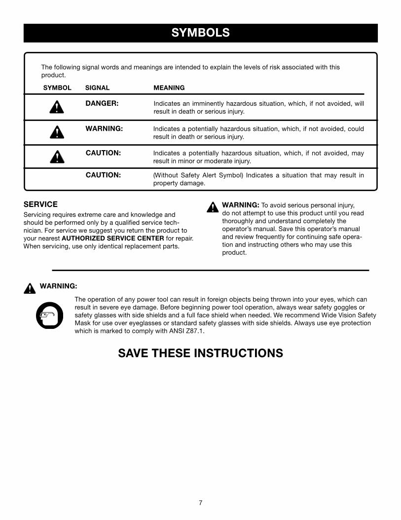
The following signal words and meanings are intended to explain the levels of risk associated with thisproduct.
SYMBOL SIGNAL MEANING
DANGER: Indicates an imminently hazardous situation, which, if not avoided, will result in death or serious injury.
WARNING: Indicates a potentially hazardous situation, which, if not avoided, could result in death or serious injury.
CAUTION: Indicates a potentially hazardous situation, which, if not avoided, may result in minor or moderate injury.
CAUTION: (Without Safety Alert Symbol) Indicates a situation that may result in property damage.
8 9
ELECTRICAL
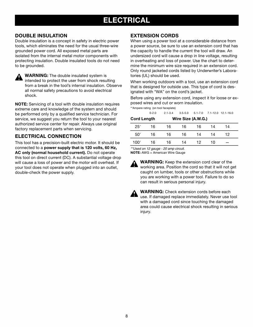
EXTENSION CORDSWhen using a power tool at a considerable distance from a power source, be sure to use an extension cord that has the capacity to handle the current the tool will draw. An undersized cord will cause a drop in line voltage, resulting in overheating and loss of power. Use the chart to deter-mine the minimum wire size required in an extension cord. Only round jacketed cords listed by Underwriter’s Labora-tories (UL) should be used.
When working outdoors with a tool, use an extension cord that is designed for outside use. This type of cord is des-ignated with “WA” on the cord’s jacket.
Before using any extension cord, inspect it for loose or ex-posed wires and cut or worn insulation.**Ampere rating (on tool faceplate)
0-2.0 2.1-3.4 3.5-5.0 5.1-7.0 7.1-12.0 12.1-16.0
Cord Length Wire Size (A.W.G.)
25' 16 16 16 16 14 14
50' 16 16 16 14 14 12
100' 16 16 14 12 10 —**Used on 12 gauge - 20 amp circuit.NOTE: AWG = American Wire Gauge
WARNING: Keep the extension cord clear of the working area. Position the cord so that it will not get caught on lumber, tools or other obstructions while you are working with a power tool. Failure to do so can result in serious personal injury.
WARNING: Check extension cords before each use. If damaged replace immediately. Never use tool with a damaged cord since touching the damaged area could cause electrical shock resulting in serious injury.
DOUBLE INSULATIONDouble insulation is a concept in safety in electric power tools, which eliminates the need for the usual three-wire grounded power cord. All exposed metal parts are isolated from the internal metal motor components with protecting insulation. Double insulated tools do not need to be grounded.
WARNING: The double insulated system is intended to protect the user from shock resulting from a break in the tool’s internal insulation. Observe all normal safety precautions to avoid electrical shock.
NOTE: Servicing of a tool with double insulation requires extreme care and knowledge of the system and should be performed only by a qualified service technician. For service, we suggest you return the tool to your nearest authorized service center for repair. Always use original factory replacement parts when servicing.
ELECTRICAL CONNECTIONThis tool has a precision-built electric motor. It should be connected to a power supply that is 120 volts, 60 Hz, AC only (normal household current). Do not operate this tool on direct current (DC). A substantial voltage drop will cause a loss of power and the motor will overheat. If your tool does not operate when plugged into an outlet, double-check the power supply.
8 9
GLOSSARY OF TERMS
Non-Through CutsAny cutting operation where the blade does not extend completely through the thickness of the workpiece.
Push Blocks and Push SticksDevices used to feed the workpiece through the saw blade during cutting operations. A push stick (not a push block) should be used for narrow ripping operations. These aids help keep the operator's hands well away from the blade.
Pilot Hole (drill presses)A small hole drilled in a workpiece that serves as a guide for drilling large holes accurately.
ResawA cutting operation to reduce the thickness of the work-piece to make thinner pieces.
ResinA sticky, sap-based substance that has hardened.
Revolutions Per Minute (RPM)The number of turns completed by a spinning object in one minute.
Ripping or Rip CutA cutting operation along the length of the workpiece.
Riving Knife (table saws)Also known as a spreader or splitter. A metal piece, slight-ly thinner than the saw blade, which helps keep the kerf open and also helps to prevent kickback.
Saw Blade PathThe area over, under, behind, or in front of the blade. As it applies to the workpiece, that area which will be or has been cut by the blade.
SetThe distance that the tip of the saw blade tooth is bent (or set) outward from the face of the blade.
Snipe (planers)Depression made at either end of a workpiece by cutter blades when the workpiece is not properly supported.
Throw-BackThe throwing back of a workpiece usually caused by the workpiece being dropped into the blade or being placed inadvertently in contact with the blade.
Through SawingAny cutting operation where the blade extends completely through the thickness of the workpiece.
Workpiece or MaterialThe item on which the operation is being done.
WorktableSurface where the workpiece rests while performing acutting, drilling, planing, or sanding operation.
Anti-Kickback Pawls (radial arm and table saws)A devise which, when properly installed and maintained, is designed to stop the workpiece from being kicked back toward the front of the saw during a ripping operation.
ArborThe shaft on which a blade or cutting tool is mounted.
Bevel CutA cutting operation made with the blade at any angle other than 90° to the table surface.
ChamferA cut removing a wedge from a block so the end (or part of the end) is angled rather than at 90°.
Compound CutA cross cut made with both a miter and a bevel angle.
CrosscutA cutting or shaping operation made across the grain or the width of the workpiece.
Cutter Head (planers and jointers)A rotating piece of adjustable blades. The cutter headremoves material from the workpiece.
Dado CutA non-through cut which produces a square-sided notch or trough in the workpiece (requires a special blade).
FeatherboardA device used to help control the workpiece by guiding it securely against the table or fence during any rippingoperation.
FPM or SPMFeet per minute (or strokes per minute), used in reference to blade movement.
FreehandPerforming a cut without the workpiece being guided by a fence, miter gauge, or other aids.
GumA sticky, sap-based residue from wood products.
HeelAlignment of the blade to the fence.
KerfThe material removed by the blade in a through cut or the slot produced by the blade in a non-through or partial cut.
KickbackA hazard that can occur when the blade binds or stalls, throwing the workpiece back toward operator.
Leading EndThe end of the workpiece pushed into the tool first.
Miter CutA cutting operation made with the workpiece at any angle to the blade other than 90°.
10 11
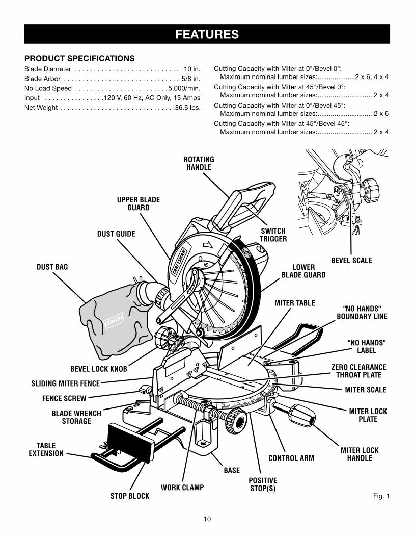
PRODUCT SPECIFICATIONSBlade Diameter . . . . . . . . . . . . . . . . . . . . . . . . . . . . 10 in.Blade Arbor . . . . . . . . . . . . . . . . . . . . . . . . . . . . . . . 5/8 in.No Load Speed . . . . . . . . . . . . . . . . . . . . . . . . . 5,000/min.Input . . . . . . . . . . . . . . . .120 V, 60 Hz, AC Only, 15 AmpsNet Weight . . . . . . . . . . . . . . . . . . . . . . . . . . . . . . .36.5 lbs.
FEATURES
Fig. 1
BASE
Cutting Capacity with Miter at 0°/Bevel 0°: Maximum nominal lumber sizes:....................2 x 6, 4 x 4
Cutting Capacity with Miter at 45°/Bevel 0°: Maximum nominal lumber sizes:............................. 2 x 4
Cutting Capacity with Miter at 0°/Bevel 45°: Maximum nominal lumber sizes:............................. 2 x 6
Cutting Capacity with Miter at 45°/Bevel 45°: Maximum nominal lumber sizes:............................. 2 x 4
UPPER BLADE GUARD
ROTATING HANDLE
SWITCH TRIGGER
LOWERBLADE GUARD
MITER TABLE
"NO HANDS" LABEL
MITER SCALE
"NO HANDS" BOUNDARY LINE
MITER LOCK HANDLE
MITER LOCK PLATE
CONTROL ARM
POSITIVE STOP(S)WORK CLAMP
DUST BAG
STOP BLOCK
TABLEEXTENSION
BEVEL LOCK KNOB
DUST GUIDE
SLIDING MITER FENCE
FENCE SCREW
ZERO CLEARANCE THROAT PLATE
BEVEL SCALE
BLADE WRENCH STORAGE
10 11
SPINDLELOCK BUTTON
SWITCHTRIGGER
Fig. 3
FEATURES
PADLOCK
SWITCHTRIGGER
Fig. 4
Fig. 2
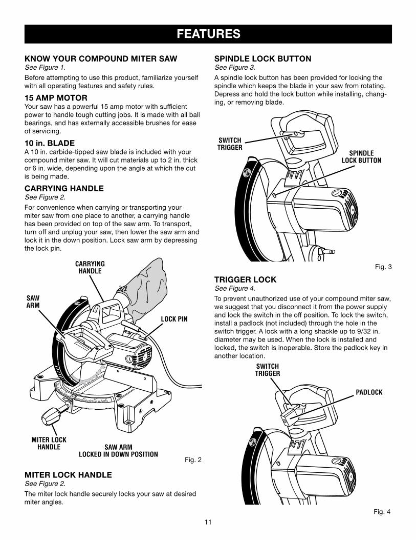
KNOW YOUR COMPOUND MITER SAWSee Figure 1.
Before attempting to use this product, familiarize yourself with all operating features and safety rules.
15 AMP MOTORYour saw has a powerful 15 amp motor with sufficient power to handle tough cutting jobs. It is made with all ball bearings, and has externally accessible brushes for ease of servicing.
10 in. BLADEA 10 in. carbide-tipped saw blade is included with your compound miter saw. It will cut materials up to 2 in. thick or 6 in. wide, depending upon the angle at which the cut is being made.
CARRYING HANDLESee Figure 2.
For convenience when carrying or transporting your miter saw from one place to another, a carrying handle has been provided on top of the saw arm. To transport, turn off and unplug your saw, then lower the saw arm and lock it in the down position. Lock saw arm by depressing the lock pin.
SPINDLE LOCK BUTTONSee Figure 3.
A spindle lock button has been provided for locking the spindle which keeps the blade in your saw from rotating. Depress and hold the lock button while installing, chang-ing, or removing blade.
TRIGGER LOCKSee Figure 4.
To prevent unauthorized use of your compound miter saw, we suggest that you disconnect it from the power supply and lock the switch in the off position. To lock the switch, install a padlock (not included) through the hole in the switch trigger. A lock with a long shackle up to 9/32 in. diameter may be used. When the lock is installed and locked, the switch is inoperable. Store the padlock key in another location.
SAW ARMLOCKED IN DOWN POSITION
LOCK PIN
MITER LOCK HANDLESee Figure 2.
The miter lock handle securely locks your saw at desired miter angles.
CARRYINGHANDLE
SAWARM
MITER LOCKHANDLE
12 13
FEATURES
POSITIVE STOPS ON MITER TABLEPositive stops have been provided at 0°, 15°, 22-1/2°, 30°, and 45° on both the left and right side of the miter table.
BEVEL LOCK KNOBThe bevel lock knob securely locks your compoundmiter saw at desired bevel angles. A positive stopadjustment screw has been provided on each side of the saw arm. These adjustment screws are for making fine adjustments at 0° and 45°.
ELECTRIC BRAKEAn electric brake has been provided to quickly stop blade rotation after the switch is released.
SLIDING MITER FENCEThe miter fence on your compound miter saw has been provided to hold your workpiece securely against when making all cuts; the left side is also larger providing addi-tional support. It has a sliding feature for clearance of the saw arm when making bevel or compound cuts.
Loosen the fence screw before attempting to slide the mi-ter fence. Once the desired position of the miter fence is determined, tighten the fence screw to secure the sliding fence.
SELF-RETRACTING LOWER BLADE GUARDThe lower blade guard is made of shock-resistant, see-through plastic that provides protection from each side of the blade. It retracts over the upper blade guard as the saw is lowered into the workpiece.
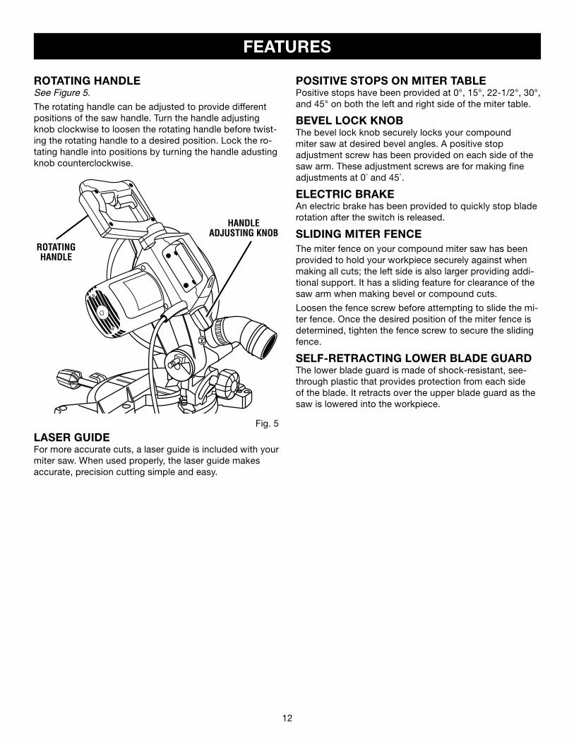
ROTATING HANDLESee Figure 5.
The rotating handle can be adjusted to provide different positions of the saw handle. Turn the handle adjusting knob clockwise to loosen the rotating handle before twist-ing the rotating handle to a desired position. Lock the ro-tating handle into positions by turning the handle adusting knob counterclockwise.
HANDLEADJUSTING KNOB
ROTATING HANDLE
Fig. 5
LASER GUIDEFor more accurate cuts, a laser guide is included with your miter saw. When used properly, the laser guide makesaccurate, precision cutting simple and easy.

12 13
The following tools (not included) are needed for checking adjustments of your saw or for installing the blade:
TOOLS NEEDED
COMBINATION SQUARE
FRAMING SQUARE
COMBINATION WRENCH (2)10 mm,14 mm
Fig. 6
PHILLIPS SCREWDRIVER
14 15
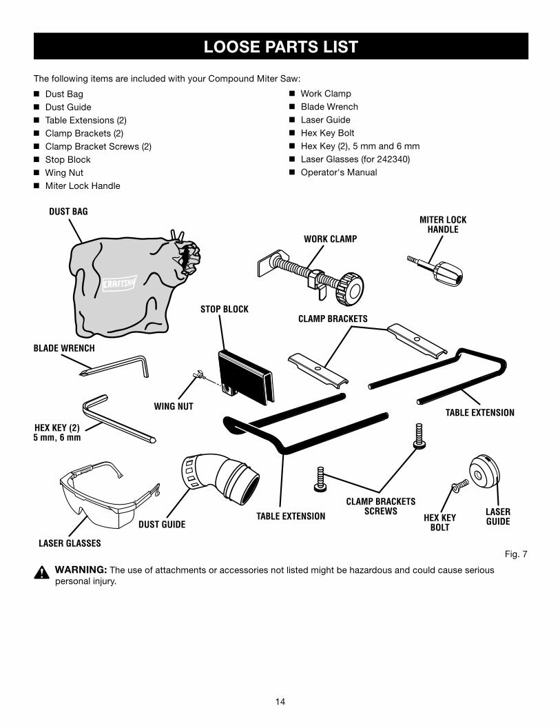
LOOSE PARTS LIST
Fig. 7
WARNING: The use of attachments or accessories not listed might be hazardous and could cause seriouspersonal injury.
n Dust Bagn Dust Guiden Table Extensions (2)n Clamp Brackets (2)n Clamp Bracket Screws (2)n Stop Blockn Wing Nutn Miter Lock Handle
The following items are included with your Compound Miter Saw:
n Work Clampn Blade Wrenchn Laser Guiden Hex Key Boltn Hex Key (2), 5 mm and 6 mmn Laser Glasses (for 242340)n Operator's Manual
DUST BAG
DUST GUIDE
CLAMP BRACKETS
TABLE EXTENSION
HEX KEY (2)5 mm, 6 mm
MITER LOCK HANDLE
CLAMP BRACKETS SCREWS
WING NUT
WORK CLAMP
TABLE EXTENSION
STOP BLOCK
BLADE WRENCH
HEX KEY BOLT
LASER GUIDE
LASER GLASSES
14 15
UNPACKINGThis product requires assembly.
n Carefully lift saw from the carton by the carrying handle and the saw base, and place it on a level work surface.
NOTE: This saw is heavy. To avoid back injury, lift with your legs, not your back, and get help when needed.
n This saw has been shipped with the saw arm secured in the down position. To release the saw arm, push down on the top of the saw arm, cut the tie-wrap, and pull out on the lock pin.
n Lift the saw arm by the handle. Hand pressure should remain on the saw arm to prevent sudden rise upon release of the tie wrap.
n Inspect the tool carefully to make sure no breakage or damage occurred during shipping.
n Do not discard the packing material until you have carefully inspected and satisfactorily operated the tool.
n The saw is factory set for accurate cutting. Afterassembling it, check for accuracy. If shipping has influenced the settings, refer to specific procedures explained in this manual.
n If any parts are damaged or missing, please call1-800-932-3188 for assistance.
WARNING: If any parts are missing, do not operate this tool until the missing parts are replaced. Failure to do so could result in possible serious personal injury.
ASSEMBLY
WARNING: Do not attempt to modify this tool or create accessories not recommended for use with this tool. Any such alteration or modification is misuse and could result in a hazardous condition leading to possible serious personal injury.
WARNING: Do not connect to power supply until assembly is complete. Failure to comply could result in accidental starting and possible serious personal injury.
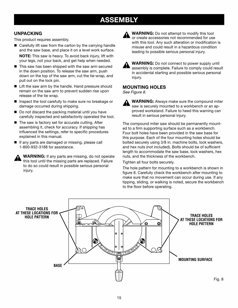
MOUNTING HOLESSee Figure 8.
WARNING: Always make sure the compound miter saw is securely mounted to a workbench or an ap-proved workstand. Failure to heed this warning can result in serious personal injury.
The compound miter saw should be permanently mount-ed to a firm supporting surface such as a workbench. Four bolt holes have been provided in the saw base for this purpose. Each of the four mounting holes should be bolted securely using 3/8 in. machine bolts, lock washers, and hex nuts (not included). Bolts should be of sufficient length to accommodate the saw base, lock washers, hex nuts, and the thickness of the workbench.
Tighten all four bolts securely.
The hole pattern for mounting to a workbench is shown in figure 8. Carefully check the workbench after mounting to make sure that no movement can occur during use. If any tipping, sliding, or walking is noted, secure the workbench to the floor before operating.
Fig. 8
��
TRACE HOLESAT THESE LOCATIONS FOR
HOLE PATTERN
TRACE HOLESAT THESE LOCATIONS FOR
HOLE PATTERN
MOUNTING SURFACEBASE
16 17
ASSEMBLY
DUST GUIDE
EXHAUSTPORT
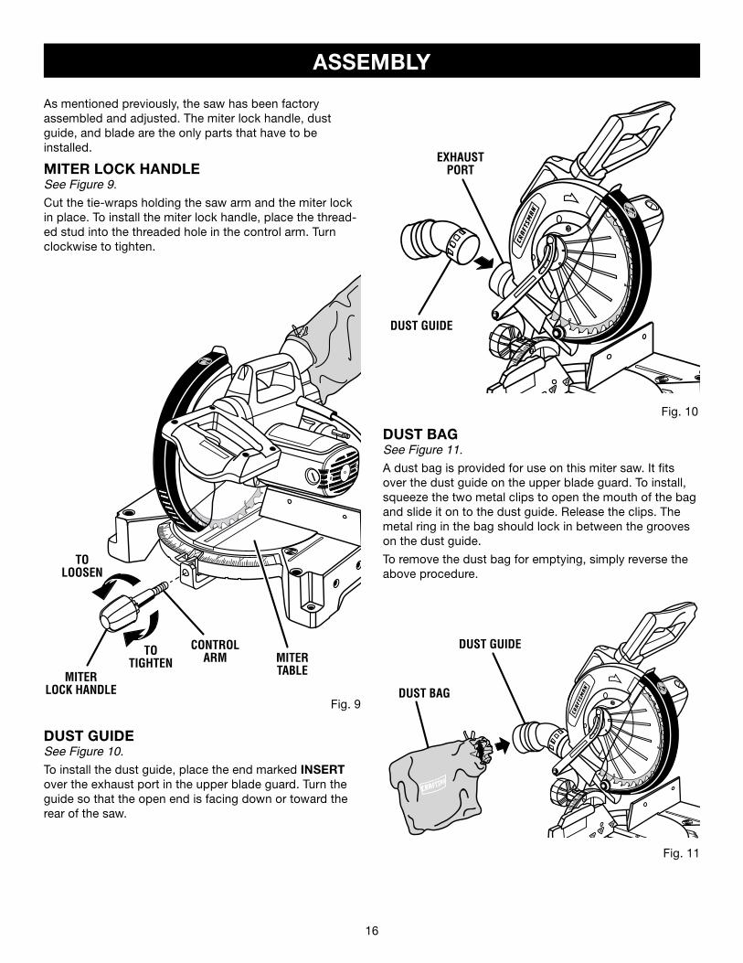
DUST GUIDESee Figure 10.
To install the dust guide, place the end marked INSERT over the exhaust port in the upper blade guard. Turn the guide so that the open end is facing down or toward the rear of the saw.
Fig. 11
DUST BAG
DUST GUIDE
DUST BAGSee Figure 11.
A dust bag is provided for use on this miter saw. It fits over the dust guide on the upper blade guard. To install, squeeze the two metal clips to open the mouth of the bag and slide it on to the dust guide. Release the clips. The metal ring in the bag should lock in between the grooves on the dust guide.
To remove the dust bag for emptying, simply reverse the above procedure.
Fig. 10
As mentioned previously, the saw has been factoryassembled and adjusted. The miter lock handle, dust guide, and blade are the only parts that have to beinstalled.
MITER LOCK HANDLESee Figure 9.
Cut the tie-wraps holding the saw arm and the miter lock in place. To install the miter lock handle, place the thread-ed stud into the threaded hole in the control arm. Turn clockwise to tighten.
Fig. 9
TOLOOSEN
TOTIGHTEN
CONTROLARM MITER
TABLEMITERLOCK HANDLE
16 17
Fig. 12
SAW VIEWED FROM BOTTOM
MITERSAW BASE
TABLEEXTENSION
ASSEMBLY
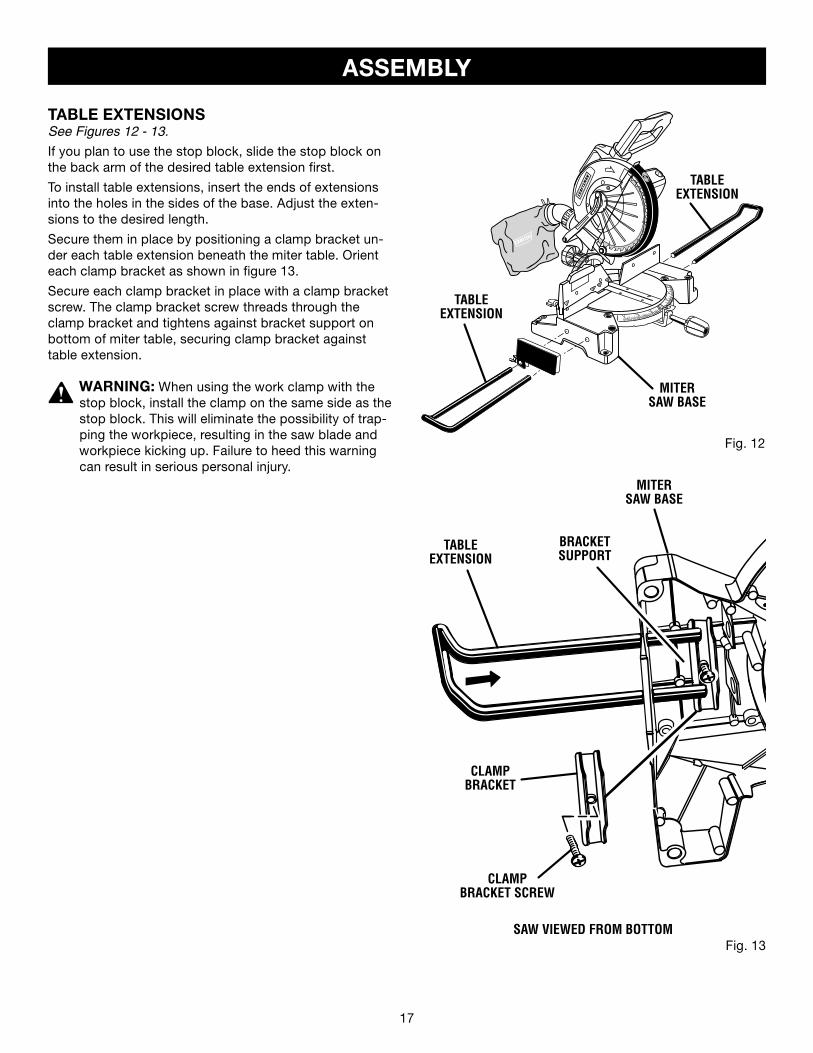
TABLE EXTENSIONSSee Figures 12 - 13.
If you plan to use the stop block, slide the stop block on the back arm of the desired table extension first.
To install table extensions, insert the ends of extensions into the holes in the sides of the base. Adjust the exten-sions to the desired length.
Secure them in place by positioning a clamp bracket un-der each table extension beneath the miter table. Orient each clamp bracket as shown in figure 13.
Secure each clamp bracket in place with a clamp bracket screw. The clamp bracket screw threads through the clamp bracket and tightens against bracket support on bottom of miter table, securing clamp bracket against table extension.
WARNING: When using the work clamp with the stop block, install the clamp on the same side as the stop block. This will eliminate the possibility of trap-ping the workpiece, resulting in the saw blade and workpiece kicking up. Failure to heed this warning can result in serious personal injury.
TABLEEXTENSION
MITERSAW BASE
BRACKETSUPPORT
CLAMPBRACKET SCREW
CLAMPBRACKET
TABLEEXTENSION
Fig. 13
18 19
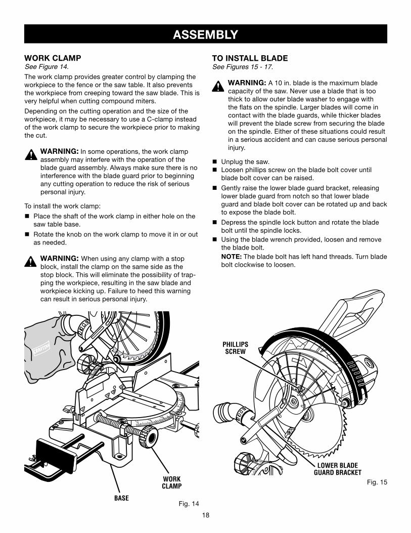
TO INSTALL BLADESee Figures 15 - 17.
WARNING: A 10 in. blade is the maximum blade capacity of the saw. Never use a blade that is too thick to allow outer blade washer to engage with the flats on the spindle. Larger blades will come in contact with the blade guards, while thicker blades will prevent the blade screw from securing the blade on the spindle. Either of these situations could result in a serious accident and can cause serious personal injury.
n Unplug the saw.n Loosen phillips screw on the blade bolt cover until
blade bolt cover can be raised.
n Gently raise the lower blade guard bracket, releasing lower blade guard from notch so that lower blade guard and blade bolt cover can be rotated up and back to expose the blade bolt.
n Depress the spindle lock button and rotate the blade bolt until the spindle locks.
n Using the blade wrench provided, loosen and remove the blade bolt.
NOTE: The blade bolt has left hand threads. Turn blade bolt clockwise to loosen.
ASSEMBLY
WORK CLAMPSee Figure 14.
The work clamp provides greater control by clamping the workpiece to the fence or the saw table. It also prevents the workpiece from creeping toward the saw blade. This is very helpful when cutting compound miters.
Depending on the cutting operation and the size of the workpiece, it may be necessary to use a C-clamp instead of the work clamp to secure the workpiece prior to making the cut.
WARNING: In some operations, the work clamp assembly may interfere with the operation of the blade guard assembly. Always make sure there is no interference with the blade guard prior to beginning any cutting operation to reduce the risk of serious personal injury.
To install the work clamp:
n Place the shaft of the work clamp in either hole on the saw table base.
n Rotate the knob on the work clamp to move it in or out as needed.
WARNING: When using any clamp with a stop block, install the clamp on the same side as the stop block. This will eliminate the possibility of trap-ping the workpiece, resulting in the saw blade and workpiece kicking up. Failure to heed this warning can result in serious personal injury.
BASE
WORK CLAMP Fig. 15
Fig. 14
�
��
�
�
��
�
LOWER BLADEGUARD BRACKET
PHILLIPS SCREW
18 19
Fig. 16
ASSEMBLY
Fig. 17
SPINDLELOCK
BUTTON
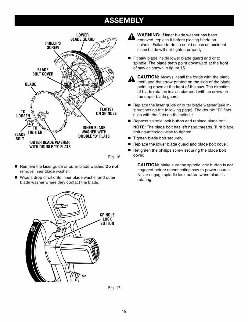
n Remove the laser guide or outer blade washer. Do not remove inner blade washer.
n Wipe a drop of oil onto inner blade washer and outer blade washer where they contact the blade.
WARNING: If inner blade washer has been removed, replace it before placing blade on spindle. Failure to do so could cause an accident since blade will not tighten properly.
n Fit saw blade inside lower blade guard and onto spindle. The blade teeth point downward at the front of saw as shown in figure 15.
CAUTION: Always install the blade with the blade teeth and the arrow printed on the side of the blade pointing down at the front of the saw. The direction of blade rotation is also stamped with an arrow on the upper blade guard.
n Replace the laser guide or outer blade washer (see in-structions on the following page). The double "D" flats align with the flats on the spindle.
n Depress spindle lock button and replace blade bolt.
NOTE: The blade bolt has left hand threads. Turn blade bolt counterclockwise to tighten.
n Tighten blade bolt securely.
n Replace the lower blade guard and blade bolt cover.
n Retighten the phillips screw securing the blade bolt cover.
CAUTION: Make sure the spindle lock button is not engaged before reconnecting saw to power source. Never engage spindle lock button when blade is rotating.
BLADEBOLT COVER
LOWERBLADE GUARD
FLAT(S)ON SPINDLE
INNER BLADEWASHER WITH
DOUBLE "D" FLATSOUTER BLADE WASHERWITH DOUBLE "D" FLATS
BLADE
BLADE BOLT
TOTIGHTEN
TOLOOSEN
PHILLIPSSCREW
20 21
ASSEMBLY
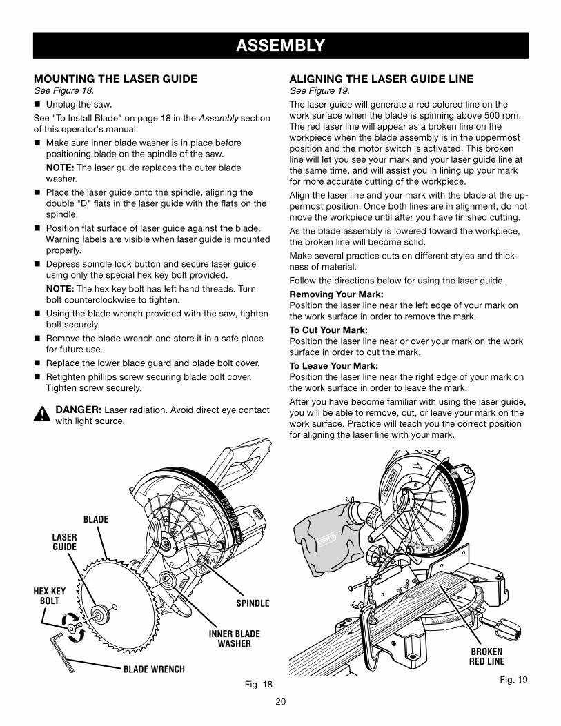
MOUNTING THE LASER GUIDESee Figure 18.
n Unplug the saw.
See "To Install Blade" on page 18 in the Assembly section of this operator's manual.
n Make sure inner blade washer is in place before positioning blade on the spindle of the saw.
NOTE: The laser guide replaces the outer blade washer.
n Place the laser guide onto the spindle, aligning the double "D" flats in the laser guide with the flats on the spindle.
n Position flat surface of laser guide against the blade. Warning labels are visible when laser guide is mounted properly.
n Depress spindle lock button and secure laser guideusing only the special hex key bolt provided.
NOTE: The hex key bolt has left hand threads. Turn bolt counterclockwise to tighten.
n Using the blade wrench provided with the saw, tighten bolt securely.
n Remove the blade wrench and store it in a safe place for future use.
n Replace the lower blade guard and blade bolt cover.
n Retighten phillips screw securing blade bolt cover. Tighten screw securely.
DANGER: Laser radiation. Avoid direct eye contact with light source.
ALIGNING THE LASER GUIDE LINESee Figure 19.
The laser guide will generate a red colored line on the work surface when the blade is spinning above 500 rpm. The red laser line will appear as a broken line on the workpiece when the blade assembly is in the uppermost position and the motor switch is activated. This broken line will let you see your mark and your laser guide line at the same time, and will assist you in lining up your mark for more accurate cutting of the workpiece.
Align the laser line and your mark with the blade at the up-permost position. Once both lines are in alignment, do not move the workpiece until after you have finished cutting.
As the blade assembly is lowered toward the workpiece, the broken line will become solid.
Make several practice cuts on different styles and thick-ness of material.
Follow the directions below for using the laser guide.
Removing Your Mark:Position the laser line near the left edge of your mark on the work surface in order to remove the mark.
To Cut Your Mark:Position the laser line near or over your mark on the work surface in order to cut the mark.
To Leave Your Mark:Position the laser line near the right edge of your mark on the work surface in order to leave the mark.
After you have become familiar with using the laser guide, you will be able to remove, cut, or leave your mark on the work surface. Practice will teach you the correct position for aligning the laser line with your mark.
Fig. 18 Fig. 19
BROKENRED LINE
�
BLADE
LASERGUIDE
SPINDLE
INNER BLADEWASHER
HEX KEYBOLT
BLADE WRENCH
20 21
ASSEMBLY
Fig. 23
FENCE
SOCKET HEAD SCREW(S)
Fig. 21
VIEW OF MITER TABLE NOT SQUARE WITHFENCE, ADJUSTMENTS ARE REQUIRED
Fig. 22
VIEW OF MITER TABLE NOT SQUARE WITHFENCE, ADJUSTMENTS ARE REQUIRED
Fig. 20
VIEW OF MITER TABLE SQUARE WITH FENCECORRECTLY ADJUSTED
FENCE
MITER TABLE
THROAT PLATE
FRAMING SQUARE
FENCE MITER TABLE
THROAT PLATE
FRAMING SQUARE
FENCE
MITER TABLE
THROAT PLATE
FRAMING SQUARE
SOCKET HEAD SCREW(S)
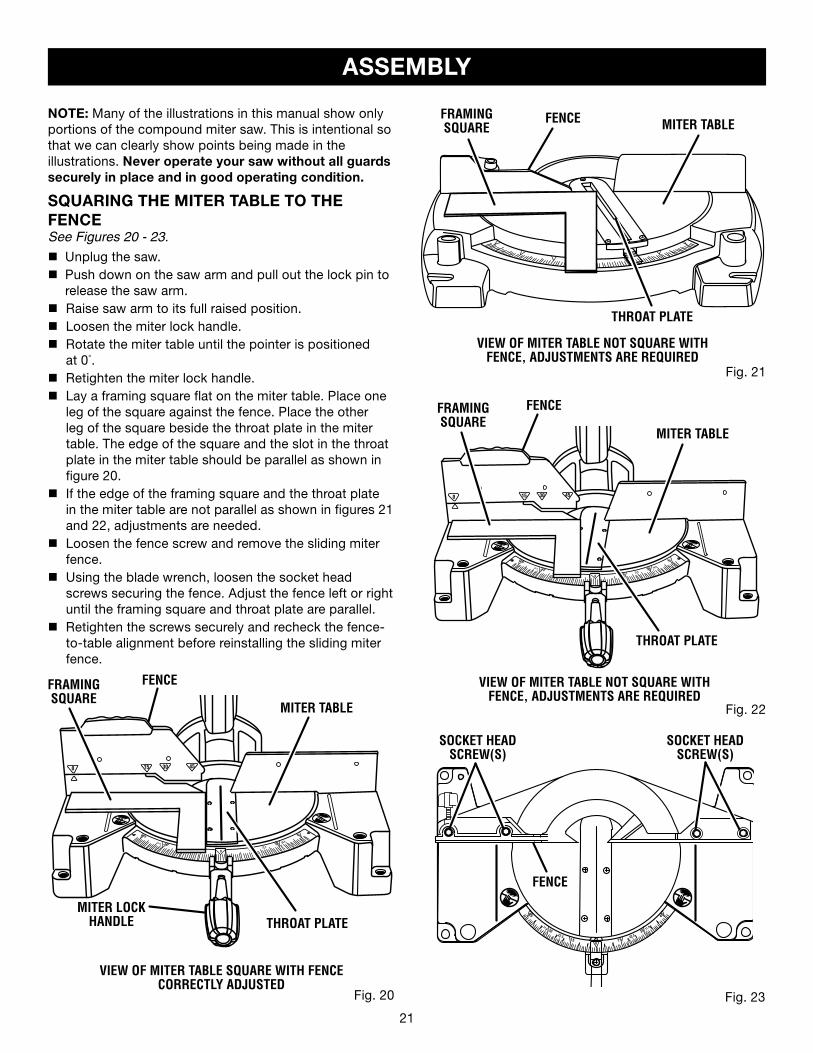
NOTE: Many of the illustrations in this manual show only portions of the compound miter saw. This is intentional so that we can clearly show points being made in theillustrations. Never operate your saw without all guards securely in place and in good operating condition.
SQUARING THE MITER TABLE TO THE FENCESee Figures 20 - 23.
n Unplug the saw.n Push down on the saw arm and pull out the lock pin to
release the saw arm.n Raise saw arm to its full raised position.n Loosen the miter lock handle.n Rotate the miter table until the pointer is positioned
at 0°.n Retighten the miter lock handle.n Lay a framing square flat on the miter table. Place one
leg of the square against the fence. Place the other leg of the square beside the throat plate in the miter table. The edge of the square and the slot in the throat plate in the miter table should be parallel as shown in figure 20.
n If the edge of the framing square and the throat plate in the miter table are not parallel as shown in figures 21 and 22, adjustments are needed.
n Loosen the fence screw and remove the sliding miter fence.
n Using the blade wrench, loosen the socket head screws securing the fence. Adjust the fence left or right until the framing square and throat plate are parallel.
n Retighten the screws securely and recheck the fence-to-table alignment before reinstalling the sliding miter fence.
��MITER LOCK HANDLE
22 23
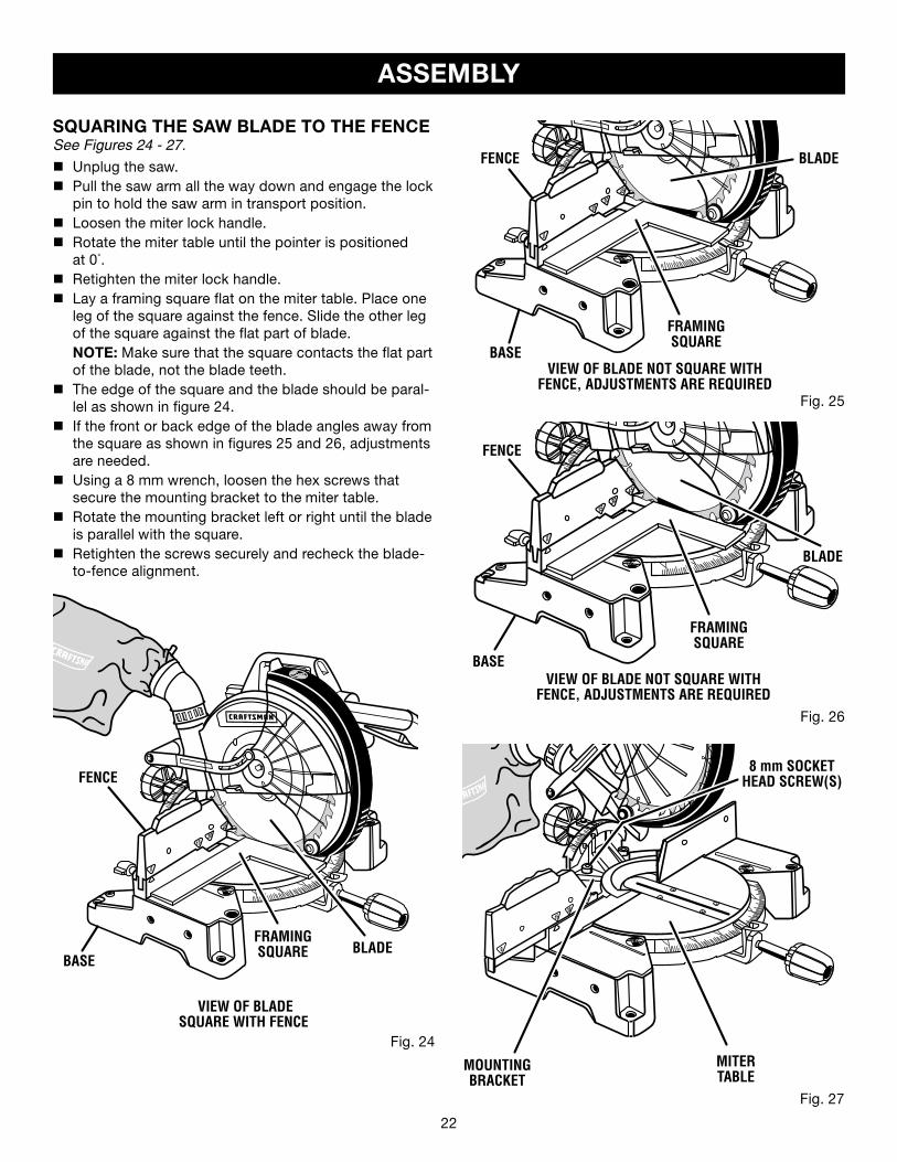
SQUARING THE SAW BLADE TO THE FENCESee Figures 24 - 27.
n Unplug the saw.n Pull the saw arm all the way down and engage the lock
pin to hold the saw arm in transport position.n Loosen the miter lock handle.n Rotate the miter table until the pointer is positioned
at 0°.n Retighten the miter lock handle.n Lay a framing square flat on the miter table. Place one
leg of the square against the fence. Slide the other leg of the square against the flat part of blade.
NOTE: Make sure that the square contacts the flat part of the blade, not the blade teeth.
n The edge of the square and the blade should be paral-lel as shown in figure 24.
n If the front or back edge of the blade angles away from the square as shown in figures 25 and 26, adjustments are needed.
n Using a 8 mm wrench, loosen the hex screws that secure the mounting bracket to the miter table.
n Rotate the mounting bracket left or right until the blade is parallel with the square.
n Retighten the screws securely and recheck the blade-to-fence alignment.
ASSEMBLY
VIEW OF BLADE NOT SQUARE WITHFENCE, ADJUSTMENTS ARE REQUIRED
Fig. 26
Fig. 25
VIEW OF BLADE NOT SQUARE WITHFENCE, ADJUSTMENTS ARE REQUIRED
Fig. 24
BASEBLADE
FENCE
BASE
BLADEFENCE
FRAMINGSQUARE
BASE
BLADE
FENCE
FRAMINGSQUARE
Fig. 27
MOUNTINGBRACKET
MITERTABLE
8 mm SOCKET HEAD SCREW(S)
FRAMINGSQUARE
VIEW OF BLADE SQUARE WITH FENCE
22 23
ASSEMBLY
FENCE
MITERTABLE
COMBINATIONSQUARE
BLADE
Fig. 28
CORRECT VIEW OF BLADESQUARE WITH MITER TABLE
VIEW OF BLADE NOT SQUARE WITH MITERTABLE, ADJUSTMENTS ARE REQUIRED
Fig. 29
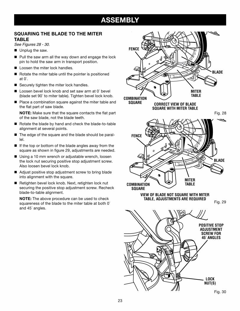
SQUARING THE BLADE TO THE MITERTABLESee Figures 28 - 30.
n Unplug the saw.
n Pull the saw arm all the way down and engage the lock pin to hold the saw arm in transport position.
n Loosen the miter lock handles.
n Rotate the miter table until the pointer is positionedat 0°.
n Securely tighten the miter lock handles.
n Loosen bevel lock knob and set saw arm at 0° bevel (blade set 90° to miter table). Tighten bevel lock knob.
n Place a combination square against the miter table and the flat part of saw blade.
NOTE: Make sure that the square contacts the flat part of the saw blade, not the blade teeth.
n Rotate the blade by hand and check the blade-to-table alignment at several points.
n The edge of the square and the blade should be paral-lel.
n If the top or bottom of the blade angles away from the square as shown in figure 29, adjustments are needed.
n Using a 10 mm wrench or adjustable wrench, loosen the lock nut securing positive stop adjustment screw. Also loosen bevel lock knob.
n Adjust positive stop adjustment screw to bring blade into alignment with the square.
n Retighten bevel lock knob. Next, retighten lock nut securing the positive stop adjustment screw. Recheck blade-to-table alignment.
NOTE: The above procedure can be used to check squareness of the blade to the miter table at both 0° and 45° angles.
FENCE
MITERTABLECOMBINATION
SQUARE
BLADE
Fig. 30
LOCK NUT(S)
POSITIVE STOPADJUSTMENTSCREW FOR45° ANGLES
24 25
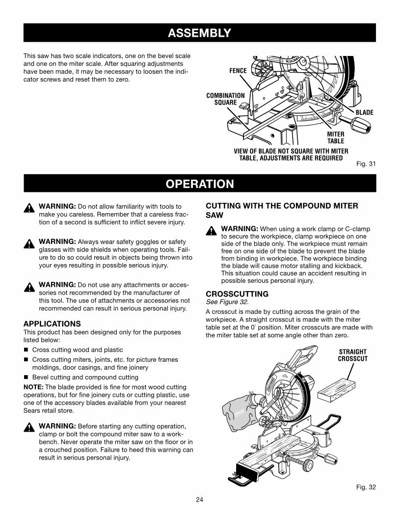
This saw has two scale indicators, one on the bevel scale and one on the miter scale. After squaring adjustments have been made, it may be necessary to loosen the indi-cator screws and reset them to zero.
Fig. 31
VIEW OF BLADE NOT SQUARE WITH MITER TABLE, ADJUSTMENTS ARE REQUIRED
ASSEMBLY
OPERATION
WARNING: Do not allow familiarity with tools to make you careless. Remember that a careless frac-tion of a second is sufficient to inflict severe injury.
WARNING: Always wear safety goggles or safety glasses with side shields when operating tools. Fail-ure to do so could result in objects being thrown into your eyes resulting in possible serious injury.
WARNING: Do not use any attachments or acces-sories not recommended by the manufacturer of this tool. The use of attachments or accessories not recommended can result in serious personal injury.
APPLICATIONSThis product has been designed only for the purposes listed below:
n Cross cutting wood and plastic
n Cross cutting miters, joints, etc. for picture frames moldings, door casings, and fine joinery
n Bevel cutting and compound cutting
NOTE: The blade provided is fine for most wood cutting operations, but for fine joinery cuts or cutting plastic, use one of the accessory blades available from your nearest Sears retail store.
WARNING: Before starting any cutting operation, clamp or bolt the compound miter saw to a work-bench. Never operate the miter saw on the floor or in a crouched position. Failure to heed this warning can result in serious personal injury.
CUTTING WITH THE COMPOUND MITER SAW
WARNING: When using a work clamp or C-clamp to secure the workpiece, clamp workpiece on one side of the blade only. The workpiece must remain free on one side of the blade to prevent the blade from binding in workpiece. The workpiece binding the blade will cause motor stalling and kickback. This situation could cause an accident resulting in possible serious personal injury.
CROSSCUTTINGSee Figure 32.
A crosscut is made by cutting across the grain of the workpiece. A straight crosscut is made with the miter table set at the 0° position. Miter crosscuts are made with the miter table set at some angle other than zero.
STRAIGHT CROSSCUT
Fig. 32
FENCE
MITERTABLE
BLADE
COMBINATIONSQUARE
24 25
TO MITER CUTn Pull out the lock pin and lift saw arm to its full height.n Loosen the miter lock handles. n Rotate the saw table until the pointer aligns with the
desired angle on the miter scale.n Reighten the miter lock handles securely.
WARNING: To avoid serious personal injury, always tighten the miter lock handle securely before making a cut. Failure to do so could result in movement of the control arm or miter table while making a cut.
n Place the workpiece flat on the miter table with one edge securely against the fence. If the board is warped, place the convex side against the fence. If the concave edge of a board is placed against the fence, the board could collapse on the blade at the end of the cut, jamming the blade.
n When cutting long pieces of lumber or molding, support the opposite end of the stock with a roller stand or with a work surface level with the saw table. See Figure 37.
n Align cutting line on the workpiece with the edge of blade.
n Grasp the stock firmly with one hand and secure it against the fence or use the optional work clamp or a C-clamp to secure the workpiece.
WARNING: To avoid serious personal injury, keep hands outside the no hands zone; at least 3 in. from blade. Never perform any cutting operation freehand (without holding workpiece against the fence). The blade could grab the workpiece if it slips or twists.
n Before turning on the saw, perform a dry run of the cutting operation just to make sure that no problems will occur when the cut is made.
n Grasp the saw handle firmly then squeeze the switch trigger. Allow several seconds for the blade to reach maximum speed.
n Slowly lower the blade into and through the workpiece.
n Release the switch trigger and allow the blade to stop rotating before raising the blade out of workpiece. Wait until the electric brake stops blade from turning before removing the workpiece from the miter table.
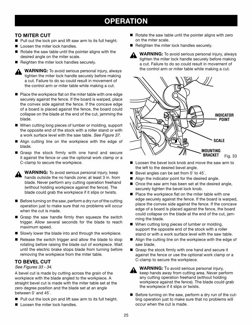
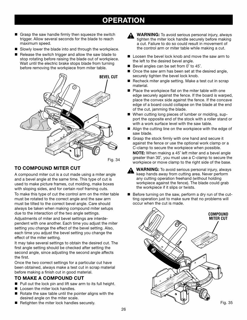
TO BEVEL CUTSee Figures 33 - 34.
A bevel cut is made by cutting across the grain of the workpiece with the blade angled to the workpiece. A straight bevel cut is made with the miter table set at the zero degree position and the blade set at an angle between 0° and 45°.
n Pull out the lock pin and lift saw arm to its full height.n Loosen the miter lock handles.
OPERATION
Fig. 33MOUNTING BRACKET
INDICATORPOINT
SCALE
n Rotate the saw table until the pointer aligns with zero on the miter scale.
n Retighten the miter lock handles securely.
WARNING: To avoid serious personal injury, always tighten the miter lock handle securely before making a cut. Failure to do so could result in movement of the control arm or miter table while making a cut.
n Loosen the bevel lock knob and move the saw arm to the left to the desired bevel angle.
n Bevel angles can be set from 0° to 45°. n Align the indicator point for the desired angle.n Once the saw arm has been set at the desired angle,
securely tighten the bevel lock knob. n Place the workpiece flat on the miter table with one
edge securely against the fence. If the board is warped, place the convex side against the fence. If the concave edge of a board is placed against the fence, the board could collapse on the blade at the end of the cut, jam-ming the blade.
n When cutting long pieces of lumber or molding, support the opposite end of the stock with a roller stand or with a work surface level with the saw table.
n Align the cutting line on the workpiece with the edge of saw blade.
n Grasp the stock firmly with one hand and secure it against the fence or use the optional work clamp or a C-clamp to secure the workpiece.
WARNING: To avoid serious personal injury, keep hands away from cutting area. Never perform any cutting operation freehand (without holding workpiece against the fence). The blade could grab the workpiece if it slips or twists.
n Before turning on the saw, perform a dry run of the cut-ting operation just to make sure that no problems will occur when the cut is made.
26 27
Fig. 34
BEVEL CUT
OPERATION
TO COMPOUND MITER CUTA compound miter cut is a cut made using a miter angle and a bevel angle at the same time. This type of cut is used to make picture frames, cut molding, make boxes with sloping sides, and for certain roof framing cuts. To make this type of cut the control arm on the miter table must be rotated to the correct angle and the saw arm must be tilted to the correct bevel angle. Care should always be taken when making compound miter setups due to the interaction of the two angle settings. Adjustments of miter and bevel settings are interde-pendent with one another. Each time you adjust the miter setting you change the effect of the bevel setting. Also, each time you adjust the bevel setting you change the effect of the miter setting.It may take several settings to obtain the desired cut. The first angle setting should be checked after setting the second angle, since adjusting the second angle affects the first.Once the two correct settings for a particular cut have been obtained, always make a test cut in scrap material before making a finish cut in good material.
TO MAKE A COMPOUND CUT n Pull out the lock pin and lift saw arm to its full height.n Loosen the miter lock handles. n Rotate the saw table until the pointer aligns with the
desired angle on the miter scale.n �Retighten the miter lock handles securely.
WARNING: To avoid serious personal injury, always tighten the miter lock handle securely before making a cut. Failure to do so could result in movement of the control arm or miter table while making a cut.
n Loosen the bevel lock knob and move the saw arm to the left to the desired bevel angle.
n Bevel angles can be set from 0˚ to 45˚.n Once the saw arm has been set at the desired angle,
securely tighten the bevel lock knob.n Recheck miter angle setting. Make a test cut in scrap
material.n Place the workpiece flat on the miter table with one
edge securely against the fence. If the board is warped, place the convex side against the fence. If the concave edge of a board could collapse on the blade at the end of the cut, jamming the blade.
n When cutting long pieces of lumber or molding, sup-port the opposite end of the stock with a roller stand or with a work surface level with the saw table.
n Align the cutting line on the workpiece with the edge of saw blade.
n Grasp the stock firmly with one hand and secure it against the fence or use the optional work clamp or a C-clamp to secure the workpiece when possible.
NOTE: When making a 45˚ left miter and a bevel angle greater than 30˚, you must use a C-clamp to secure the workpiece or move clamp to the right side of the base.
WARNING: To avoid serious personal injury, always keep hands away from cutting area. Never perform any cutting operation freehand (without holding workpiece against the fence). The blade could grab the workpiece if it slips or twists.
n Before turning on the saw, perform a dry run of the cut-ting operation just to make sure that no problems will occur when the cut is made.
Fig. 35
COMPOUND MITER CUT
n Grasp the saw handle firmly then squeeze the switch trigger. Allow several seconds for the blade to reach maximum speed.
n Slowly lower the blade into and through the workpiece.n Release the switch trigger and allow the saw blade to
stop rotating before raising the blade out of workpiece. Wait until the electric brake stops blade from turning before removing the workpiece from miter table.
26 27
OPERATION
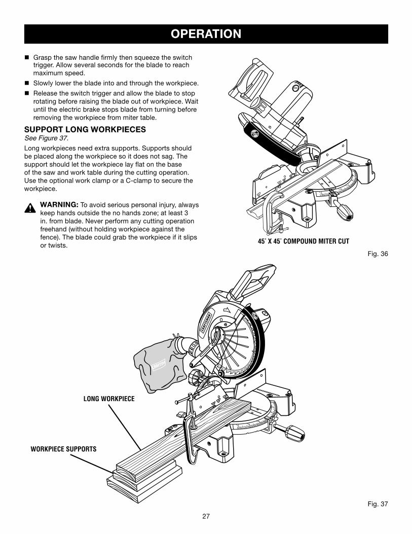
Fig. 37
Fig. 36
45° X 45° COMPOUND MITER CUT
n Grasp the saw handle firmly then squeeze the switch trigger. Allow several seconds for the blade to reach maximum speed.
n Slowly lower the blade into and through the workpiece.
n Release the switch trigger and allow the blade to stop rotating before raising the blade out of workpiece. Wait until the electric brake stops blade from turning before removing the workpiece from miter table.
SUPPORT LONG WORKPIECESSee Figure 37.
Long workpieces need extra supports. Supports should be placed along the workpiece so it does not sag. The support should let the workpiece lay flat on the base of the saw and work table during the cutting operation. Use the optional work clamp or a C-clamp to secure the workpiece.
WARNING: To avoid serious personal injury, always keep hands outside the no hands zone; at least 3 in. from blade. Never perform any cutting operation freehand (without holding workpiece against the fence). The blade could grab the workpiece if it slips or twists.
LONG WORKPIECE
WORKPIECE SUPPORTS
�

28 29
4 PITCH OF SIDE
NUMBER OF SIDES
0°
6
M- 45.00°B- 0.00°
5°
10°
15°
20°
25°
30°
35°
40°
45°
50°
55°
60°
65°
70°
75°
80°
85°
90°
5 7 8 9 10
M- 36.00°B- 0.00°
M- 30.00°B- 0.00°
M- 25.71°B- 0.00°
M- 22.50°B- 0.00°
M- 20.00°B- 0.00°
M- 18.00°B- 0.00°
Each B (Bevel) and M (Miter) Setting is Given to the Closest 0.005°.
COMPOUND-ANGLE SETTINGS FOR POPULAR STRUCTURES
M- 44.89°B- 3.53°
M- 35.90°B- 2.94°
M- 29.91°B- 2.50°
M- 25.63°B- 2.17°
M- 22.42°B- 1.91°
M- 19.93°B- 1.71°
M- 17.94°B- 1.54°
M- 7.82°B -16.26°
M- 14.51°B- 43.08°
CUTTING COMPOUND MITERSTo aid in making the correct settings, the compound angle setting chart below has been provided. Since compound cuts are the most difficult to accurately obtain, trial cuts should be made in scrap material, and much thought and planning made, prior to making your required cut.
M- 44.56°B- 7.05°
M- 35.58°B- 5.86°
M- 29.62°B- 4.98°
M- 25.37°B- 4.32°
M- 22.19°B- 3.81°
M- 19.72°B- 3.40°
M- 17.74°B- 3.08°
M- 44.01°B- 10.55°
M- 43.22°B- 14.00°M- 42.19°B- 17.39°
M- 4.98°B- 44.78°
M- 0.00°B- 45.00°
M- 9.85°B- 44.14°
M- 18.88°B- 41.64°
M- 22.91°B- 39.86°
M- 26.57°B- 37.76°
M- 29.84°B- 35.40°
M- 32.73°B- 32.80°
M- 35.26°B- 30.00°
M- 37.45°B- 27.03°
M- 39.32°B- 23.93°
M- 40.89°B- 20.70°
M- 35.06°B- 8.75°
M- 29.15°B- 7.44°
M- 24.95°B- 6.45°
M- 21.81°B- 5.68°
M- 19.37°B- 5.08°
M- 17.42°B- 4.59°
M- 34.32°B- 11.60°
M- 28.48°B- 9.85°
M- 24.35°B- 8.53°
M- 21.27°B- 7.52°
M- 18.88°B- 6.72°
M- 16.98°B- 6.07°
M- 33.36°B- 14.38°
M- 27.62°B- 12.20°
M- 23.56°B- 10.57°
M- 20.58°B- 9.31°
M- 18.26°B- 8.31°
M- 16.41°B- 7.50°
M- 32.18°B- 17.09°
M- 26.57°B- 14.48°
M- 22.64°B- 12.53°
M- 19.73°B- 11.03°
M- 17.50°B- 9.85°
M- 15.72°B- 8.89°
M- 30.76°B- 19.70°
M- 25.31°B- 16.67°
M- 21.53°B- 14.41°
M- 18.74°B- 12.68°
M- 16.60°B- 11.31°
M- 14.90°B- 10.21°
M- 29.10°B- 22.20°
M- 23.86°B- 18.75°
M- 20.25°B- 16.19°
M- 17.60°B- 14.24°
M- 15.58°B- 12.70°
M- 13.98°B- 11.46°
M- 0.00°B- 36.00°
M- 0.00°B- 30.00°
M- 0.00°B- 25.71°
M- 0.00°B- 22.50°
M- 0.00°B- 20.00°
M- 0.00°B- 18.00°
M- 3.62°B- 35.84°
M- 2.88°B- 29.87°
M- 2.40°B- 25.61°
M- 2.07°B- 22.41°
M- 1.82°B- 19.92°
M- 1.62°B- 17.93°
M- 7.19°B- 35.37°
M- 5.73°B- 29.50°
M- 4.78°B- 25.30°
M- 4.11°B- 22.14°
M- 3.62°B- 19.68°
M- 3.23°B- 17.72°
M- 10.65°B- 34.59°
M- 8.50°B- 28.88°
M- 7.10°B- 24.78°
M- 6.12°B- 21.69°
M- 5.38°B- 19.29°
M- 4.81°B- 17.37°
M- 13.95°B- 33.53°
M- 11.17°B- 28.02°
M- 9.35°B- 24.06°
M- 8.06°B- 21.08°
M- 7.10°B- 18.75°
M- 6.34°B- 16.88°
M- 17.07°B- 32.19°
M- 13.71°B- 26.95°
M- 11.50°B- 23.16°
M- 9.93°B- 20.29°
M- 8.74°B- 18.06°
M- 19.96°B- 30.60°
M- 16.10°B- 25.66°
M- 13.54°B- 22.07°
M- 11.70°B- 19.35°
M- 10.31°B- 17.23°
M- 9.23°B- 15.52°
M- 22.62°B- 28.78°
M- 18.32°B- 24.18°
M- 15.44°B- 20.82°
M- 13.36°B- 18.27°
M- 11.79°B- 16.27°
M- 10.56°B- 14.66°
M- 25.03°B- 26.76°
M- 20.36°B- 22.52°
M- 17.20°B- 19.41°
M- 14.91°B- 17.05°
M- 13.17°B- 15.19°
M- 11.80°B- 13.69°
M- 27.19°B- 24.56°
M- 22.21°B- 20.70°
M- 18.80°B- 17.87°
M- 16.32°B- 15.70°
M- 14.43°B- 14.00°
M- 12.94°B- 12.62°
OPERATION
28 29
CUTTING CROWN MOLDINGThe compound miter saw does an excellent job of cut-ting crown molding. In general, compound miter saws do a better job of cutting crown molding than any other tool made.
In order to fit properly, crown molding must be compound mitered with extreme accuracy.
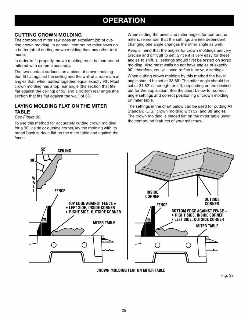
The two contact surfaces on a piece of crown molding that fit flat against the ceiling and the wall of a room are at angles that, when added together, equal exactly 90°. Most crown molding has a top rear angle (the section that fits flat against the ceiling) of 52° and a bottom rear angle (the section that fits flat against the wall) of 38°.
LAYING MOLDING FLAT ON THE MITER TABLESee Figure 38.
To use this method for accurately cutting crown molding for a 90° inside or outside corner, lay the molding with its broad back surface flat on the miter table and against the fence.
When setting the bevel and miter angles for compound miters, remember that the settings are interdependent; changing one angle changes the other angle as well.
Keep in mind that the angles for crown moldings are very precise and difficult to set. Since it is very easy for these angles to shift, all settings should first be tested on scrap molding. Also most walls do not have angles of exactly 90°, therefore, you will need to fine tune your settings.
When cutting crown molding by this method the bevel angle should be set at 33.85°. The miter angle should be set at 31.62° either right or left, depending on the desired cut for the application. See the chart below for correct angle settings and correct positioning of crown molding on miter table.
The settings in the chart below can be used for cutting All Standard (U.S.) crown molding with 52° and 38° angles. The crown molding is placed flat on the miter table using the compound features of your miter saw.
OPERATION
CEILING
WALL INSIDE
CORNER
CROWN MOLDING FLAT ON MITER TABLE
38°
52°
FENCE
MITER TABLE
BOTTOM EDGE AGAINST FENCE =RIGHT SIDE, INSIDE CORNERLEFT SIDE, OUTSIDE CORNER
FENCE
MITER TABLE
Fig. 38
OUTSIDECORNERTOP EDGE AGAINST FENCE =
LEFT SIDE, INSIDE CORNER RIGHT SIDE, OUTSIDE CORNER
30 31
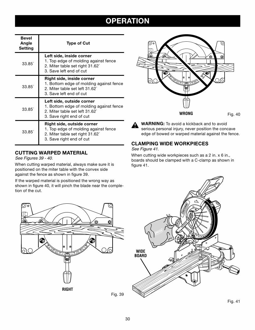
WRONG Fig. 40
WARNING: To avoid a kickback and to avoid serious personal injury, never position the concave edge of bowed or warped material against the fence.
CLAMPING WIDE WORKPIECESSee Figure 41.
When cutting wide workpieces such as a 2 in. x 6 in., boards should be clamped with a C-clamp as shown in figure 41.
Bevel Angle Type of Cut Setting
Left side, inside corner1. Top edge of molding against fence2. Miter table set right 31.62°
3. Save left end of cut
Right side, inside corner1. Bottom edge of molding against fence2. Miter table set left 31.62°
3. Save left end of cut
Left side, outside corner1. Bottom edge of molding against fence2. Miter table set left 31.62°
3. Save right end of cut
Right side, outside corner1. Top edge of molding against fence2. Miter table set right 31.62°
3. Save right end of cut
33.85°
33.85°
33.85°
33.85°
Fig. 41
CUTTING WARPED MATERIALSee Figures 39 - 40.
When cutting warped material, always make sure it is positioned on the miter table with the convex side against the fence as shown in figure 39.
If the warped material is positioned the wrong way as shown in figure 40, it will pinch the blade near the comple-tion of the cut.
Fig. 39RIGHT
WIDEBOARD
OPERATION
����
��
����
��
30 31
ADJUSTMENTS
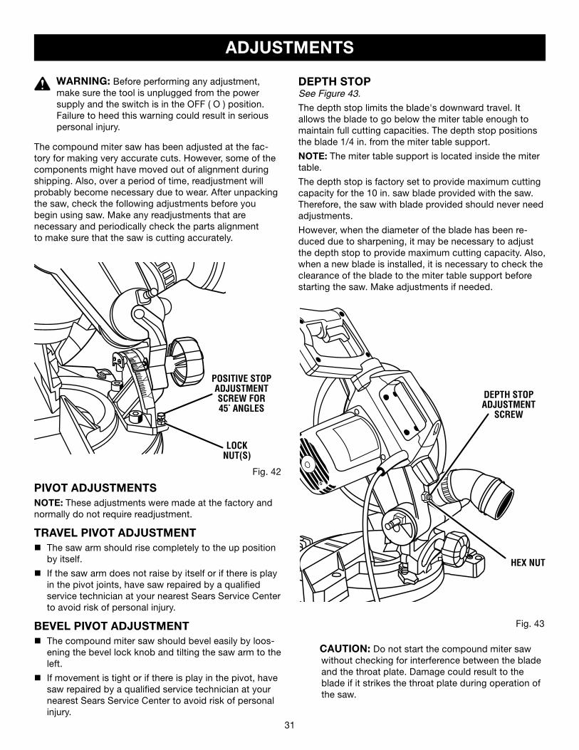
PIVOT ADJUSTMENTSNOTE: These adjustments were made at the factory and normally do not require readjustment.
TRAVEL PIVOT ADJUSTMENTn The saw arm should rise completely to the up position
by itself.
n If the saw arm does not raise by itself or if there is play in the pivot joints, have saw repaired by a qualified service technician at your nearest Sears Service Center to avoid risk of personal injury.
BEVEL PIVOT ADJUSTMENTn The compound miter saw should bevel easily by loos-
ening the bevel lock knob and tilting the saw arm to the left.
n If movement is tight or if there is play in the pivot, have saw repaired by a qualified service technician at your nearest Sears Service Center to avoid risk of personal injury.
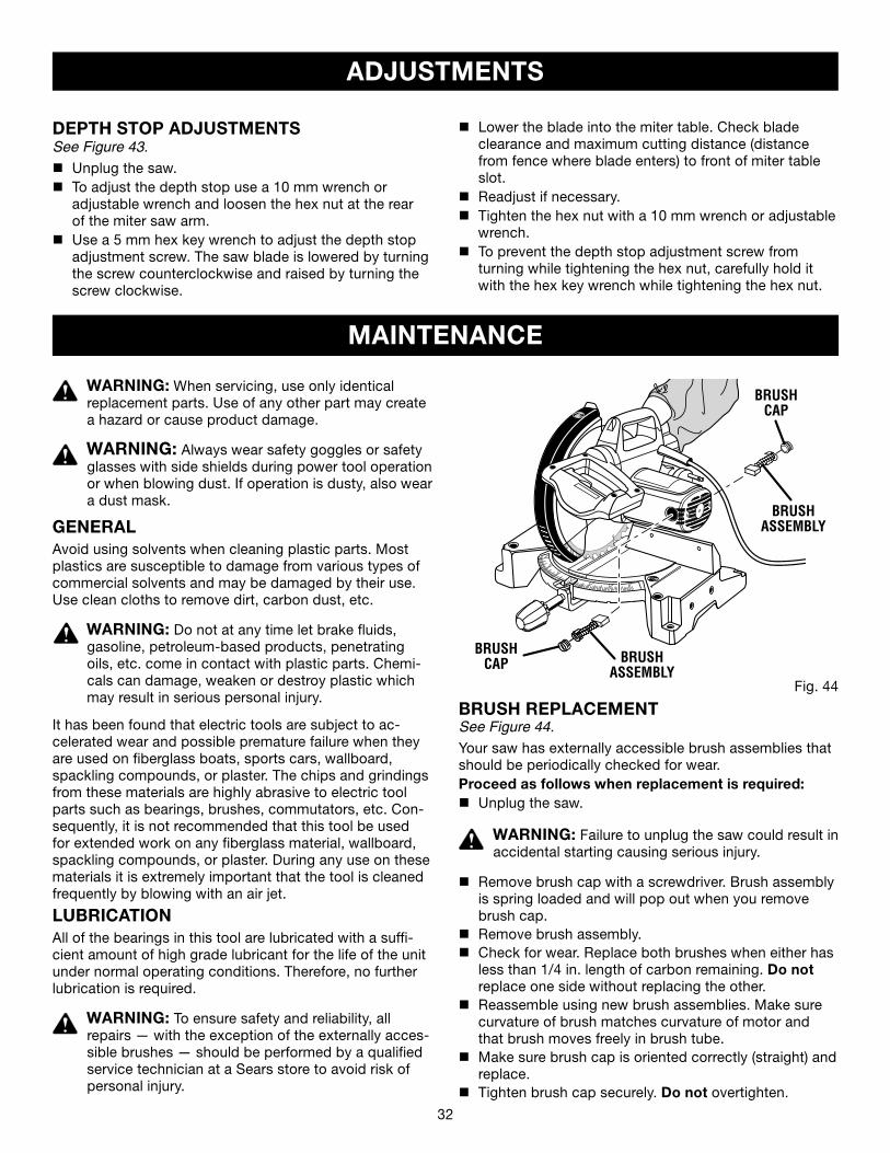
DEPTH STOPSee Figure 43.
The depth stop limits the blade's downward travel. It allows the blade to go below the miter table enough to maintain full cutting capacities. The depth stop positions the blade 1/4 in. from the miter table support.
NOTE: The miter table support is located inside the miter table.
The depth stop is factory set to provide maximum cutting capacity for the 10 in. saw blade provided with the saw. Therefore, the saw with blade provided should never need adjustments.
However, when the diameter of the blade has been re-duced due to sharpening, it may be necessary to adjust the depth stop to provide maximum cutting capacity. Also, when a new blade is installed, it is necessary to check the clearance of the blade to the miter table support before starting the saw. Make adjustments if needed.
Fig. 42
LOCK NUT(S)
WARNING: Before performing any adjustment, make sure the tool is unplugged from the power supply and the switch is in the OFF ( O ) position. Failure to heed this warning could result in serious personal injury.
The compound miter saw has been adjusted at the fac-tory for making very accurate cuts. However, some of the components might have moved out of alignment during shipping. Also, over a period of time, readjustment will probably become necessary due to wear. After unpacking the saw, check the following adjustments before youbegin using saw. Make any readjustments that arenecessary and periodically check the parts alignmentto make sure that the saw is cutting accurately.
POSITIVE STOPADJUSTMENTSCREW FOR45° ANGLES
Fig. 43
CAUTION: Do not start the compound miter saw without checking for interference between the blade and the throat plate. Damage could result to the blade if it strikes the throat plate during operation of the saw.
DEPTH STOPADJUSTMENT
SCREW
HEX NUT
32 33
ADJUSTMENTS
DEPTH STOP ADJUSTMENTSSee Figure 43.
n Unplug the saw.n To adjust the depth stop use a 10 mm wrench or
adjustable wrench and loosen the hex nut at the rear of the miter saw arm.
n Use a 5 mm hex key wrench to adjust the depth stop adjustment screw. The saw blade is lowered by turning the screw counterclockwise and raised by turning the screw clockwise.
WARNING: When servicing, use only identical replacement parts. Use of any other part may create a hazard or cause product damage.
WARNING: Always wear safety goggles or safety glasses with side shields during power tool operation or when blowing dust. If operation is dusty, also wear a dust mask.
GENERALAvoid using solvents when cleaning plastic parts. Most plastics are susceptible to damage from various types of commercial solvents and may be damaged by their use. Use clean cloths to remove dirt, carbon dust, etc.
WARNING: Do not at any time let brake fluids, gasoline, petroleum-based products, penetrating oils, etc. come in contact with plastic parts. Chemi-cals can damage, weaken or destroy plastic which may result in serious personal injury.
It has been found that electric tools are subject to ac-celerated wear and possible premature failure when they are used on fiberglass boats, sports cars, wallboard, spackling compounds, or plaster. The chips and grindings from these materials are highly abrasive to electric tool parts such as bearings, brushes, commutators, etc. Con-sequently, it is not recommended that this tool be used for extended work on any fiberglass material, wallboard, spackling compounds, or plaster. During any use on these materials it is extremely important that the tool is cleaned frequently by blowing with an air jet.
LUBRICATIONAll of the bearings in this tool are lubricated with a suffi-cient amount of high grade lubricant for the life of the unit under normal operating conditions. Therefore, no further lubrication is required.
WARNING: To ensure safety and reliability, all repairs — with the exception of the externally acces-sible brushes — should be performed by a qualified service technician at a Sears store to avoid risk of personal injury.
MAINTENANCE
Fig. 44
BRUSHCAP
BRUSHASSEMBLY
BRUSH REPLACEMENTSee Figure 44.
Your saw has externally accessible brush assemblies that should be periodically checked for wear.Proceed as follows when replacement is required:n Unplug the saw.
WARNING: Failure to unplug the saw could result in accidental starting causing serious injury.
n Remove brush cap with a screwdriver. Brush assembly is spring loaded and will pop out when you remove brush cap.
n Remove brush assembly.n Check for wear. Replace both brushes when either has
less than 1/4 in. length of carbon remaining. Do not replace one side without replacing the other.
n Reassemble using new brush assemblies. Make sure curvature of brush matches curvature of motor and that brush moves freely in brush tube.
n Make sure brush cap is oriented correctly (straight) and replace.
n Tighten brush cap securely. Do not overtighten.
BRUSHASSEMBLY
BRUSHCAP
n Lower the blade into the miter table. Check blade clearance and maximum cutting distance (distance from fence where blade enters) to front of miter table slot.
n Readjust if necessary.n Tighten the hex nut with a 10 mm wrench or adjustable
wrench.n To prevent the depth stop adjustment screw from
turning while tightening the hex nut, carefully hold it with the hex key wrench while tightening the hex nut.
32 33
MAINTENANCE
Fig. 46
��
�
� � ���
��
��
��
�
� � �� � � ��
�
��
�
�� ��� � � � �
NEGATIVE (–)
LASER GUIDESUPPORT
BATTERIES
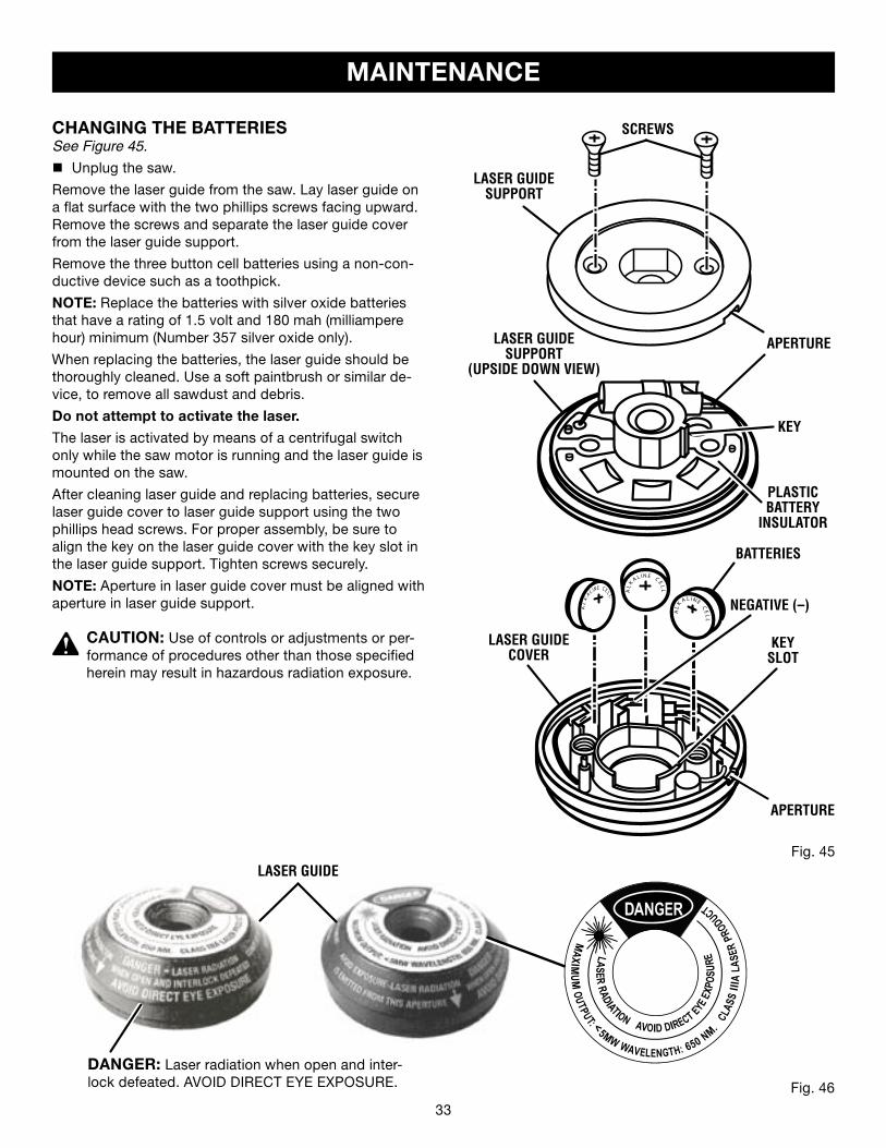
CHANGING THE BATTERIESSee Figure 45.
n Unplug the saw.
Remove the laser guide from the saw. Lay laser guide on a flat surface with the two phillips screws facing upward. Remove the screws and separate the laser guide cover from the laser guide support.
Remove the three button cell batteries using a non-con-ductive device such as a toothpick.
NOTE: Replace the batteries with silver oxide batteries that have a rating of 1.5 volt and 180 mah (milliampere hour) minimum (Number 357 silver oxide only).
When replacing the batteries, the laser guide should be thoroughly cleaned. Use a soft paintbrush or similar de-vice, to remove all sawdust and debris.
Do not attempt to activate the laser.
The laser is activated by means of a centrifugal switch only while the saw motor is running and the laser guide is mounted on the saw.
After cleaning laser guide and replacing batteries, secure laser guide cover to laser guide support using the two phillips head screws. For proper assembly, be sure to align the key on the laser guide cover with the key slot in the laser guide support. Tighten screws securely.
NOTE: Aperture in laser guide cover must be aligned with aperture in laser guide support.
CAUTION: Use of controls or adjustments or per-formance of procedures other than those specified herein may result in hazardous radiation exposure.
Fig. 45
DANGER: Laser radiation when open and inter-lock defeated. AVOID DIRECT EYE EXPOSURE.
SCREWS
LASER GUIDECOVER
LASER GUIDE
KEYSLOT
APERTURE
APERTURE
LASER GUIDESUPPORT
(UPSIDE DOWN VIEW)
KEY
PLASTICBATTERY
INSULATOR
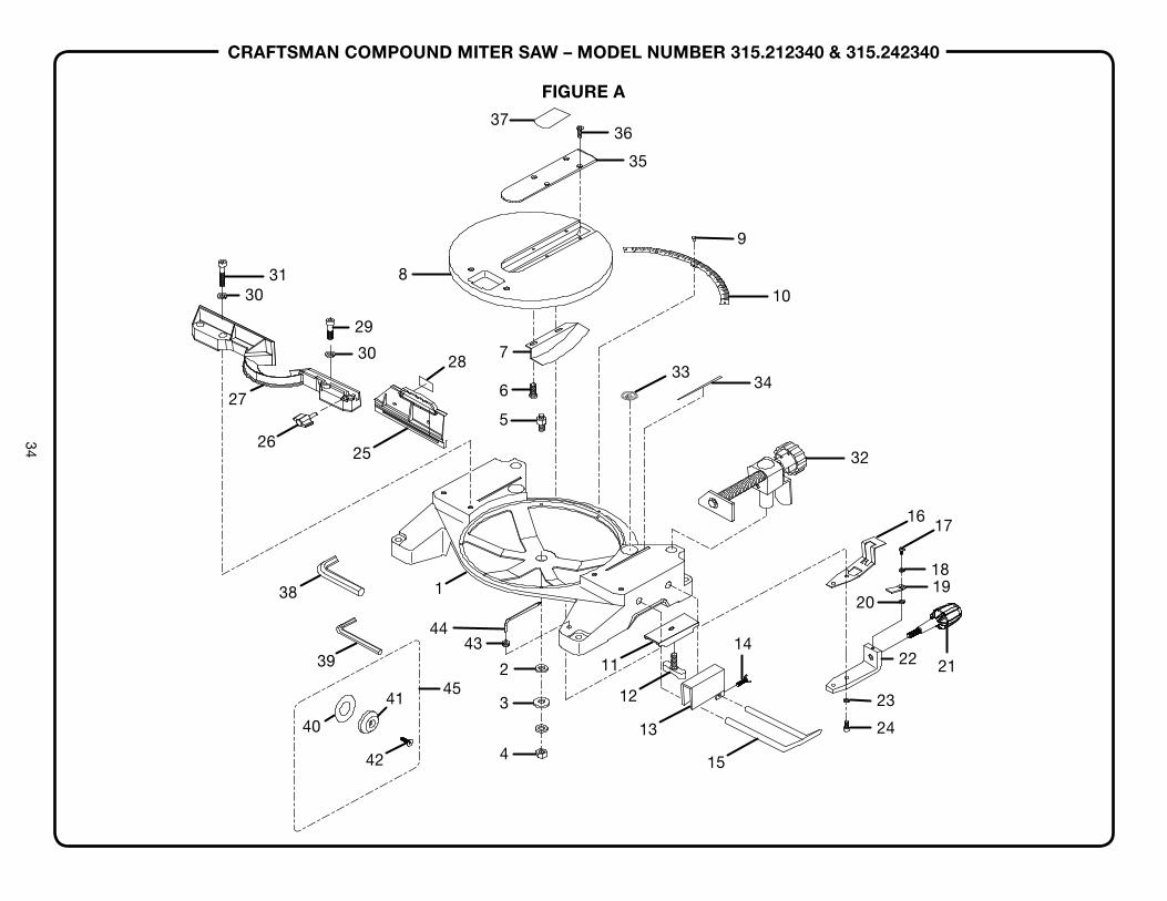
CRAFTSMAN COMPOUND MITER SAW – MODEL NUMBER 315.212340 & 315.242340
34
9
3637
10
34
32
337
28
6
5
35
4443
2 11
23
22 21
24
18
17
1920
345
4
8
29
31
25
30
27
26
30
138
39
40
41
42
16
12
13
15
14
FIGURE A
CRAFTSMAN COMPOUND MITER SAW – MODEL NUMBER 315.212340 & 315.242340
35
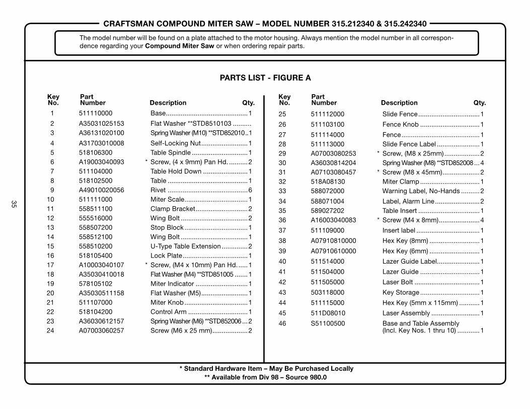
PARTS LIST - FIGURE A
Key Part No. Number Description Qty.
* Standard Hardware Item – May Be Purchased Locally** Available from Div 98 – Source 980.0
1 511110000 Base............................................1
2 A35031025153 Flat Washer **STD8510103 .......... 3 A36131020100 Spring Washer (M10) **STD852010..1
4 A31703010008 Self-Locking Nut.........................1 5 518106300 Table Spindle ..............................1 6 A19003040093 * Screw, (4 x 9mm) Pan Hd. ..........2 7 511104000 Table Hold Down ........................1 8 518102500 Table ...........................................1 9 A49010020056 Rivet ...........................................6 10 511111000 Miter Scale..................................1 11 558511100 Clamp Bracket............................2 12 555516000 Wing Bolt ....................................2 13 558507200 Stop Block..................................1 14 558512100 Wing Bolt ....................................1 15 558510200 U-Type Table Extension..............2 16 518105400 Lock Plate...................................1 17 A10003040107 * Screw, (M4 x 10mm) Pan Hd......1 18 A35030410018 Flat Washer (M4) **STD851005 .......1 19 578105102 Miter Indicator ............................1 20 A35030511158 Flat Washer (M5).........................1 21 511107000 Miter Knob..................................1 22 518104200 Control Arm ................................1 23 A36030612157 Spring Washer (M6) **STD852006...2 24 A07003060257 Screw (M6 x 25 mm)...................2
The model number will be found on a plate attached to the motor housing. Always mention the model number in all correspon-dence regarding your Compound Miter Saw or when ordering repair parts.
25 511112000 Slide Fence.................................1
26 511103100 Fence Knob ................................1
27 511114000 Fence..........................................1 28 511113000 Slide Fence Label .......................1 29 A07003080253 * Screw, (M8 x 25mm)...................2 30 A36030814204 Spring Washer (M8) **STD852008...4 31 A07103080457 * Screw (M8 x 45mm)....................2 32 518A08130 Miter Clamp................................1 33 588072000 Warning Label, No-Hands ..........2
34 588071004 Label, Alarm Line........................2 35 589027202 Table Insert .................................1 36 A16003040083 * Screw (M4 x 8mm)......................4
37 511109000 Insert label ..................................1
38 A07910810000 Hex Key (8mm) ...........................1
39 A07910610000 Hex Key (6mm) ...........................1
40 511514000 Lazer Guide Label.......................1
41 511504000 Lazer Guide ................................1
42 511505000 Laser Bolt ...................................1
43 503118000 Key Storage................................1
44 511115000 Hex Key (5mm x 115mm) ...........1
45 511D08010 Laser Assembly ..........................1
46 S51100500 Base and Table Assembly (Incl. Key Nos. 1 thru 10) ............1
Key Part No. Number Description Qty.
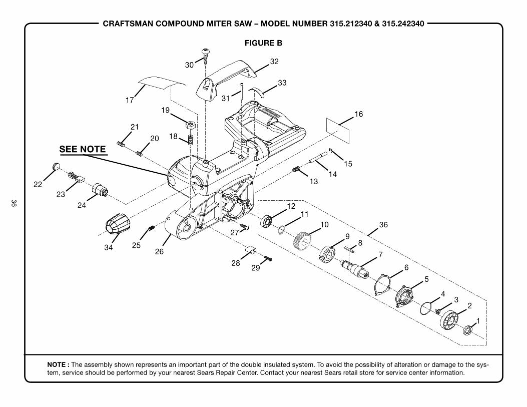
CRAFTSMAN COMPOUND MITER SAW – MODEL NUMBER 315.212340 & 315.242340
36
21
20
1917
16
33
32
31
30
1514
13
1211
10
98
7
6
5
43
2
18
2223
24
2534 26
27
28
36
29
1
FIGURE B
SEE NOTE
NOTE : The assembly shown represents an important part of the double insulated system. To avoid the possibility of alteration or damage to the sys-tem, service should be performed by your nearest Sears Repair Center. Contact your nearest Sears retail store for service center information.

CRAFTSMAN COMPOUND MITER SAW – MODEL NUMBER 315.212340 & 315.242340
37
PARTS LIST - FIGURE B Key Part No. Number Description Qty.
The model number will be found on a plate attached to the motor housing. Always mention the model number in all correspondence regarding your Compound Miter Saw or when ordering repair parts.
1 511414000 Spacer ..............................................................................................1 2 A50060030040 Ball Bearing (6003Z/RS) ...................................................................1 3 511334000 * Screw (M5 x 6mm)............................................................................2 4 A63020000350 O-Ring (S-35)....................................................................................1 5 511335000 Bearing Cover...................................................................................1 6 511336000 Gasket ..............................................................................................1 7 511337000 Gear Shaft ........................................................................................1 8 A45204040180 Key (4 X 4 X 18L) ..............................................................................1 9 588029007 Lock Ring..........................................................................................1 10 608309000 Master Gear......................................................................................1 11 A46000150008 C-Ring (S-15)....................................................................................2 12 A50060000027 Ball Bearing (6000ZZ) **STD315511.................................................1 13 588027005 Compression Spring.........................................................................1 14 588026106 Arbor Lock Pin..................................................................................1 15 A47000040006 E-Ring (E4)........................................................................................1 16 511313000 Warning Label, Motor .......................................................................1 17 511353000 Warning Label...................................................................................1 18 A18003100206 * Depth Adjusting Bolt (M10 x 20mm) ................................................1 19 A30003010007 Hex Nut (M10) **STD844010 ............................................................1 20 A18003050054 * Screw (M5 x 5mm)............................................................................2 21 A95001050060 * Screw (M5 x 6mm)............................................................................2 22 588005100 Brush Cap.........................................................................................2 23 588006100 Carbon Brush ...................................................................................2 24 588007300 Brush Holder.....................................................................................2 25 A18003050086 * Screw (M5 x 8mm)............................................................................1 26 511339000 Arm ...................................................................................................1 27 A510001040120 * Screw (M4 x 12mm)..........................................................................3 28 588021203 Rubber Stopper ................................................................................1 29 A10003040207 * Screw (M4 x 20mm)..........................................................................1 30 A70003060250 * Screw (M6 x 25mm)..........................................................................2 31 A10003050400 * Screw (M5 x 40mm)..........................................................................4 32 511311000 Carry Handle.....................................................................................1 33 511352000 Twist Handle Warning Label .............................................................1 34 511340000 Twist Handle .....................................................................................1 35 S51100700 Arbor Assembly (Includes Key Nos. 2 thru 12).................................1
* Standard Hardware Item – May Be Purchased Locally** Available from Div 98 – Source 980.0
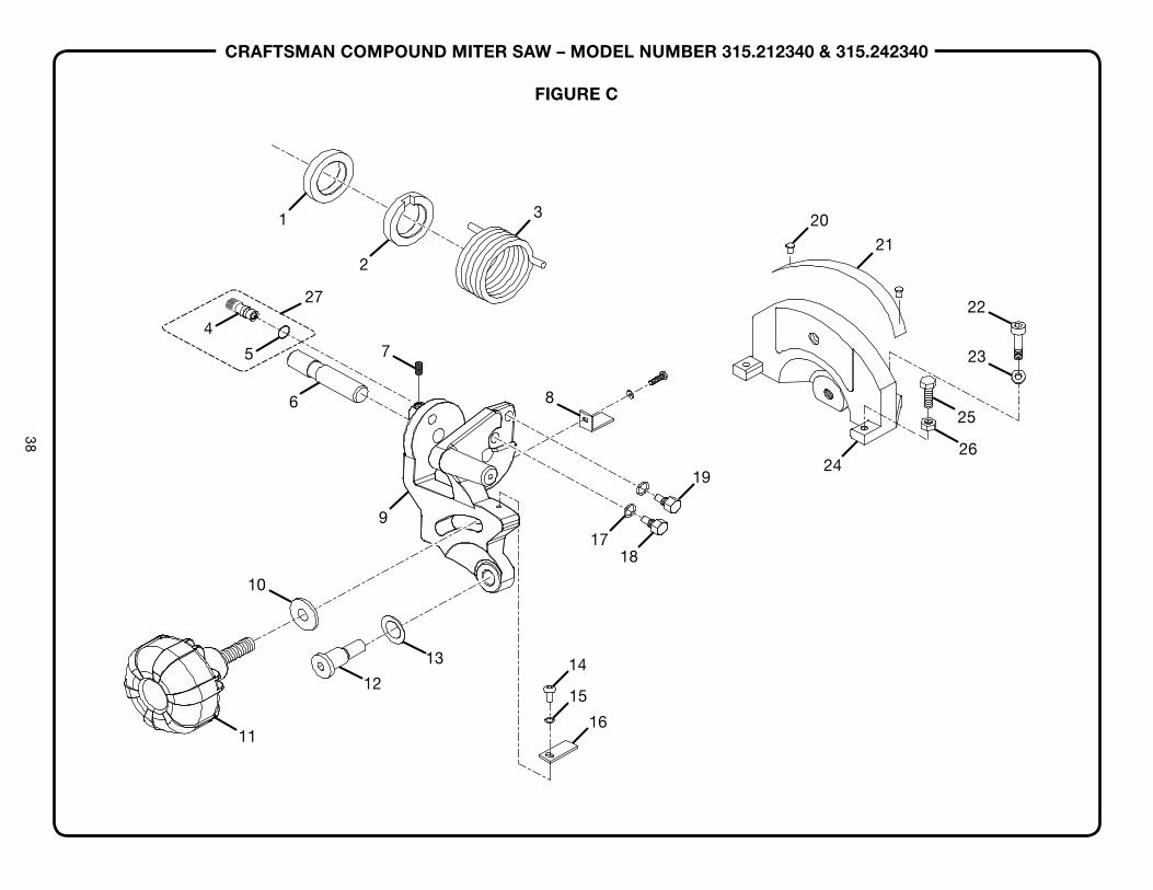
CRAFTSMAN COMPOUND MITER SAW – MODEL NUMBER 315.212340 & 315.242340
38
FIGURE C
1
2
7
3
8
1718
1924
26
25
23
22
21
20
9
10
12
11
13
6
27
5
4
15
14
16
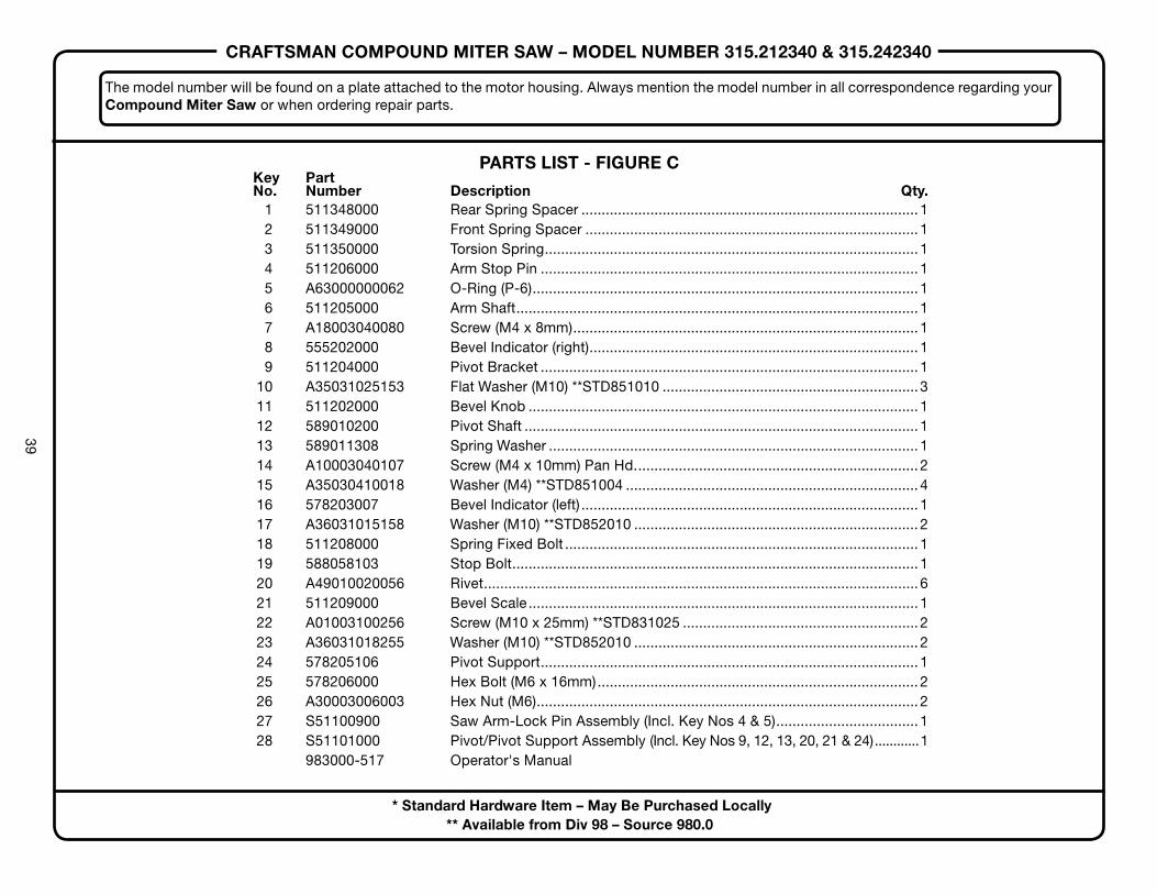
CRAFTSMAN COMPOUND MITER SAW – MODEL NUMBER 315.212340 & 315.242340
39
PARTS LIST - FIGURE C Key Part No. Number Description Qty. 1 511348000 Rear Spring Spacer ................................................................................... 1 2 511349000 Front Spring Spacer .................................................................................. 1 3 511350000 Torsion Spring............................................................................................ 1 4 511206000 Arm Stop Pin ............................................................................................. 1 5 A63000000062 O-Ring (P-6)............................................................................................... 1 6 511205000 Arm Shaft................................................................................................... 1 7 A18003040080 Screw (M4 x 8mm)..................................................................................... 1 8 555202000 Bevel Indicator (right)................................................................................. 1 9 511204000 Pivot Bracket ............................................................................................. 1 10 A35031025153 Flat Washer (M10) **STD851010 ...............................................................3 11 511202000 Bevel Knob ................................................................................................ 1 12 589010200 Pivot Shaft ................................................................................................. 1 13 589011308 Spring Washer ........................................................................................... 1 14 A10003040107 Screw (M4 x 10mm) Pan Hd...................................................................... 2 15 A35030410018 Washer (M4) **STD851004 ........................................................................ 4 16 578203007 Bevel Indicator (left) ................................................................................... 1 17 A36031015158 Washer (M10) **STD852010 ...................................................................... 2 18 511208000 Spring Fixed Bolt ....................................................................................... 1 19 588058103 Stop Bolt.................................................................................................... 1 20 A49010020056 Rivet........................................................................................................... 6 21 511209000 Bevel Scale................................................................................................ 1 22 A01003100256 Screw (M10 x 25mm) **STD831025 ..........................................................2 23 A36031018255 Washer (M10) **STD852010 ...................................................................... 2 24 578205106 Pivot Support............................................................................................. 1 25 578206000 Hex Bolt (M6 x 16mm)............................................................................... 2 26 A30003006003 Hex Nut (M6).............................................................................................. 2 27 S51100900 Saw Arm-Lock Pin Assembly (Incl. Key Nos 4 & 5)................................... 1 28 S51101000 Pivot/Pivot Support Assembly (Incl. Key Nos 9, 12, 13, 20, 21 & 24)............1 983000-517 Operator's Manual
The model number will be found on a plate attached to the motor housing. Always mention the model number in all correspondence regarding your Compound Miter Saw or when ordering repair parts.
* Standard Hardware Item – May Be Purchased Locally** Available from Div 98 – Source 980.0
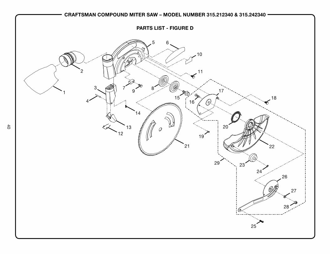
CRAFTSMAN COMPOUND MITER SAW – MODEL NUMBER 315.212340 & 315.242340
40
1
2
4
3 79
1213
14
8
5 6
10
11
17
18
19
21 22
2324
26
27
28
25
1615
20
29
PARTS LIST - FIGURE D
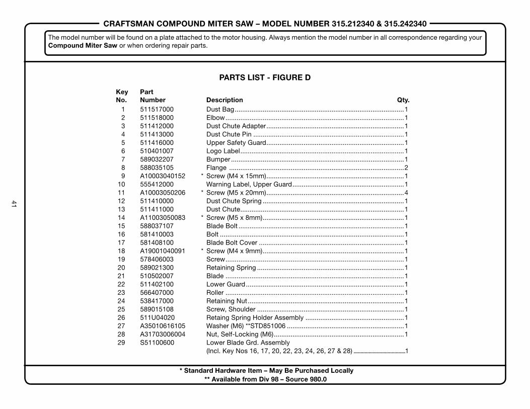
CRAFTSMAN COMPOUND MITER SAW – MODEL NUMBER 315.212340 & 315.242340
41
PARTS LIST - FIGURE D
Key Part No. Number Description Qty.
The model number will be found on a plate attached to the motor housing. Always mention the model number in all correspondence regarding your Compound Miter Saw or when ordering repair parts.
1 511517000 Dust Bag...........................................................................................1 2 511518000 Elbow................................................................................................1 3 511412000 Dust Chute Adapter..........................................................................1 4 511413000 Dust Chute Pin .................................................................................1 5 511416000 Upper Safety Guard..........................................................................1 6 510401007 Logo Label........................................................................................1 7 589032207 Bumper .............................................................................................1 8 588035105 Flange ..............................................................................................2 9 A10003040152 * Screw (M4 x 15mm)..........................................................................1 10 555412000 Warning Label, Upper Guard............................................................1 11 A10003050206 * Screw (M5 x 20mm)..........................................................................4 12 511410000 Dust Chute Spring ............................................................................1 13 511411000 Dust Chute........................................................................................1 14 A11003050083 * Screw (M5 x 8mm)............................................................................1 15 588037107 Blade Bolt .........................................................................................1 16 581410003 Bolt ...................................................................................................1 17 581408100 Blade Bolt Cover ..............................................................................1 18 A19001040091 * Screw (M4 x 9mm)............................................................................1 19 578406003 Screw................................................................................................1 20 589021300 Retaining Spring ...............................................................................1 21 510502007 Blade ................................................................................................1 22 511402100 Lower Guard.....................................................................................1 23 566407000 Roller ................................................................................................1 24 538417000 Retaining Nut....................................................................................1 25 589015108 Screw, Shoulder ...............................................................................1 26 511U04020 Retaing Spring Holder Assembly .....................................................1 27 A35010616105 Washer (M6) **STD851006 ...............................................................1 28 A31703006004 Nut, Self-Locking (M6)......................................................................1 29 S51100600 Lower Blade Grd. Assembly (Incl. Key Nos 16, 17, 20, 22, 23, 24, 26, 27 & 28) ......................................1
* Standard Hardware Item – May Be Purchased Locally** Available from Div 98 – Source 980.0

® Registered Trademark / TM Trademark / SM Service Mark of Sears, Roebuck and Co.® Marca Registrada / TM Marca de Fábrica / SM Marca de Servicio de Sears, Roebuck and Co.MC Marque de commerce / MD Marque déposée de Sears, Roebuck and Co. © Sears, Roebuck and Co.
Get it fixed, at your home or ours!
Your HomeFor repair – in your home – of all major brand appliances,
lawn and garden equipment, or heating and cooling systems,no matter who made it, no matter who sold it!
For the replacement parts, accessories andowner’s manuals that you need to do-it-yourself.
For Sears professional installation of home appliancesand items like garage door openers and water heaters.
1-800-4-MY-HOME® (1-800-469-4663)Call anytime, day or night (U.S.A. and Canada)
www.sears.com www.sears.ca
Our HomeFor repair of carry-in items like vacuums, lawn equipment,
and electronics, call or go on-line for the location of your nearestSears Parts & Repair Center.
1-800-488-1222Call anytime, day or night (U.S.A. only)
www.sears.com
To purchase a protection agreement (U.S.A.)or maintenance agreement (Canada) on a product serviced by Sears:
1-800-827-6655 (U.S.A.) 1-800-361-6665 (Canada)
Para pedir servicio de reparacióna domicilio, y para ordenar piezas:
1-888-SU-HOGARSM
(1-888-784-6427)
Au Canada pour service en français:
1-800-LE-FOYER MC
(1-800-533-6937)www.sears.ca