Embed Size (px)
Citation preview

1 CS-2511T
OPERATORS MANUALCHAIN SAW
CS-2511T
WARNINGThis chain saw is designed especially for tree service by a trained operator.Read the instructions carefully and follow the rules for safe operation.Failure to do so could result in serious injury.
X75033315021/18
ECHO, INCORPORATED400 Oakwood Road, Lake Zurich, Illinois 60047-1564Phone : 847-540-8400
THIS PRODUCT COMPLIES WITH CAN ICES-2/NMB-2

2CS-2511T
Copyright © 2017 All Rights Reserved.
The engine exhaust from this product contains chemicals known to the State of California to cause
cancer, birth defects or other reproductive harm.
WARNING
3 CS-2511T
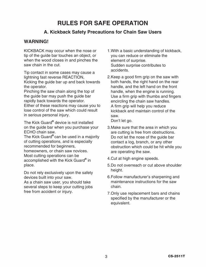
RULES FOR SAFE OPERATIONA. Kickback Safety Precautions for Chain Saw Users
1. With a basic understanding of kickback, you can reduce or eliminate the element of surprise. Sudden surprise contributes to accidents.
2. Keep a good firm grip on the saw with both hands, the right hand on the rear handle, and the left hand on the front handle, when the engine is running. Use a firm grip with thumbs and fingers encircling the chain saw handles. A firm grip will help you reduce kickback and maintain control of the saw. Don’t let go.
3. Make sure that the area in which you are cutting is free from obstructions. Do not let the nose of the guide bar contact a log, branch, or any other obstruction which could be hit while you are operating the saw.
4. Cut at high engine speeds.
5. Do not overreach or cut above shoulder height.
6. Follow manufacturer’s sharpening and maintenance instructions for the saw chain.
7. Only use replacement bars and chains specified by the manufacturer or the equivalent.
WARNING!
KICKBACK may occur when the nose or tip of the guide bar touches an object, or when the wood closes in and pinches the saw chain in the cut.
Tip contact in some cases may cause a lightning fast reverse REACTION, Kicking the guide bar up and back towards the operator. Pinching the saw chain along the top of the guide bar may push the guide bar rapidly back towards the operator. Either of these reactions may cause you to lose control of the saw which could result in serious personal injury.
The Kick Guard® device is not installed on the guide bar when you purchase your ECHO chain saw. The Kick Guard® can be used in a majority of cutting operations, and is especially recommended for beginners, homeowners, or chain saw novices. Most cutting operations can be accomplished with the Kick Guard® in place.
Do not rely exclusively upon the safety devices built into your saw. As a chain saw user, you should take several steps to keep your cutting jobs free from accident or injury.
4CS-2511T
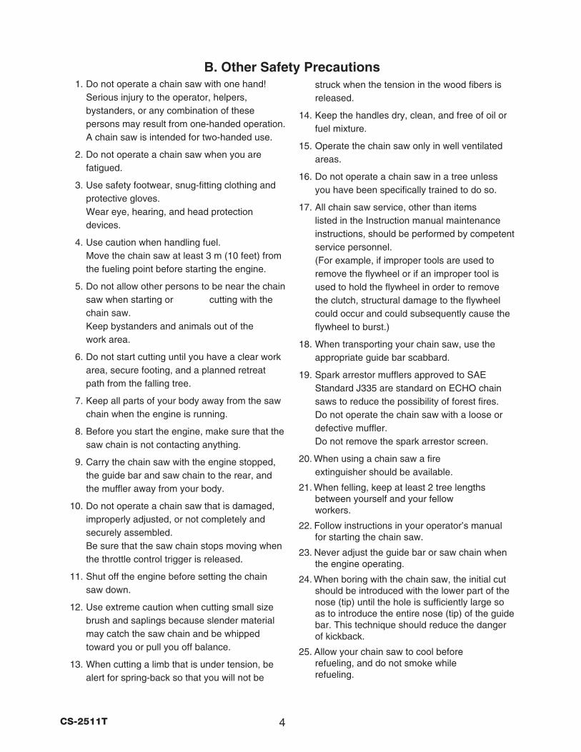
1. Do not operate a chain saw with one hand! Serious injury to the operator, helpers, bystanders, or any combination of these persons may result from one-handed operation. A chain saw is intended for two-handed use.
2. Do not operate a chain saw when you are fatigued.
3. Use safety footwear, snug-fitting clothing and protective gloves. Wear eye, hearing, and head protection devices.
4. Use caution when handling fuel. Move the chain saw at least 3 m (10 feet) from the fueling point before starting the engine.
5. Do not allow other persons to be near the chain saw when starting or cutting with the chain saw. Keep bystanders and animals out of the work area.
6. Do not start cutting until you have a clear work area, secure footing, and a planned retreat path from the falling tree.
7. Keep all parts of your body away from the saw chain when the engine is running.
8. Before you start the engine, make sure that the saw chain is not contacting anything.
9. Carry the chain saw with the engine stopped, the guide bar and saw chain to the rear, and the muffler away from your body.
10. Do not operate a chain saw that is damaged, improperly adjusted, or not completely and securely assembled. Be sure that the saw chain stops moving when the throttle control trigger is released.
11. Shut off the engine before setting the chain saw down.
12. Use extreme caution when cutting small size brush and saplings because slender material may catch the saw chain and be whipped toward you or pull you off balance.
13. When cutting a limb that is under tension, be alert for spring-back so that you will not be
struck when the tension in the wood fibers is released.
14. Keep the handles dry, clean, and free of oil or fuel mixture.
15. Operate the chain saw only in well ventilated areas.
16. Do not operate a chain saw in a tree unless you have been specifically trained to do so.
17. All chain saw service, other than items listed in the Instruction manual maintenance instructions, should be performed by competent service personnel. (For example, if improper tools are used to remove the flywheel or if an improper tool is used to hold the flywheel in order to remove the clutch, structural damage to the flywheel could occur and could subsequently cause the flywheel to burst.)
18. When transporting your chain saw, use the appropriate guide bar scabbard.
19. Spark arrestor mufflers approved to SAE Standard J335 are standard on ECHO chain saws to reduce the possibility of forest fires. Do not operate the chain saw with a loose or defective muffler. Do not remove the spark arrestor screen.
20. When using a chain saw a fire extinguisher should be available.
21. When felling, keep at least 2 tree lengths between yourself and your fellow workers.
22. Follow instructions in your operator’s manual for starting the chain saw.
23. Never adjust the guide bar or saw chain when the engine operating.
24. When boring with the chain saw, the initial cut should be introduced with the lower part of the nose (tip) until the hole is sufficiently large so as to introduce the entire nose (tip) of the guide bar. This technique should reduce the danger of kickback.
25. Allow your chain saw to cool before refueling, and do not smoke while refueling.
B. Other Safety Precautions
5 CS-2511T
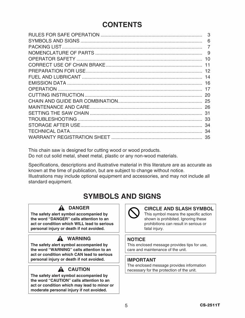
WARNINGThe safety alert symbol accompanied by the word “WARNING” calls attention to an act or condition which CAN lead to serious personal injury or death if not avoided.
CAUTIONThe safety alert symbol accompanied by the word “CAUTION” calls attention to an act or condition which may lead to minor or moderate personal injury if not avoided.
NOTICEThis enclosed message provides tips for use, care and maintenance of the unit.
IMPORTANTThe enclosed message provides information necessary for the protection of the unit.
DANGERThe safety alert symbol accompanied by the word “DANGER” calls attention to an act or condition which WILL lead to serious personal injury or death if not avoided.
SYMBOLS AND SIGNS
CONTENTSRULES FOR SAFE OPERATION ............................................................................ 3SYMBOLS AND SIGNS ........................................................................................... 6PACKING LIST ......................................................................................................... 7NOMENCLATURE OF PARTS ................................................................................ 9OPERATOR SAFETY .............................................................................................. 10CORRECT USE OF CHAIN BRAKE ........................................................................ 11PREPARATION FOR USE ....................................................................................... 12FUEL AND LUBRICANT .......................................................................................... 14EMISSION DATA ..................................................................................................... 16OPERATION ............................................................................................................ 17CUTTING INSTRUCTION ........................................................................................ 20CHAIN AND GUIDE BAR COMBINATION ............................................................... 25MAINTENANCE AND CARE .................................................................................... 26SETTING THE SAW CHAIN .................................................................................... 31TROUBLESHOOTING ............................................................................................. 33STORAGE AFTER USE ........................................................................................... 34TECHNICAL DATA ................................................................................................... 34WARRANTY REGISTRATION SHEET .................................................................... 35
This chain saw is designed for cutting wood or wood products. Do not cut solid metal, sheet metal, plastic or any non-wood materials.
Specifications, descriptions and illustrative material in this literature are as accurate as known at the time of publication, but are subject to change without notice. Illustrations may include optional equipment and accessories, and may not include all standard equipment.
CIRCLE AND SLASH SYMBOLThis symbol means the specific action shown is prohibited. Ignoring these prohibitions can result in serious or fatal injury.
6CS-2511T
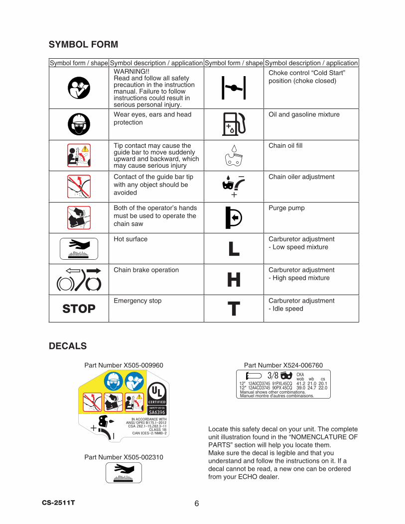
SYMBOL FORM
DECALS
Locate this safety decal on your unit. The complete unit illustration found in the “NOMENCLATURE OF PARTS” section will help you locate them. Make sure the decal is legible and that you understand and follow the instructions on it. If a decal cannot be read, a new one can be ordered from your ECHO dealer.
Part Number X505-002310
Part Number X505-009960
Symbol form / shape Symbol description / application Symbol form / shape Symbol description / applicationWARNING!! Read and follow all safety precaution in the instruction manual. Failure to follow instructions could result in serious personal injury.
Choke control “Cold Start” position (choke closed)
Wear eyes, ears and head protection
Oil and gasoline mixture
Tip contact may cause the guide bar to move suddenly upward and backward, which may cause serious injury
Chain oil fill
Contact of the guide bar tip with any object should be avoided
Chain oiler adjustment
Both of the operator’s hands must be used to operate the chain saw
Purge pump
Hot surface
LCarburetor adjustment - Low speed mixture
Chain brake operation
HCarburetor adjustment - High speed mixture
STOPEmergency stop
TCarburetor adjustment - Idle speed
Part Number X524-006760
7 CS-2511T
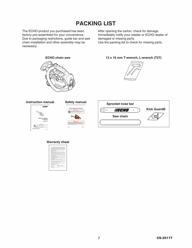
PACKING LISTThe ECHO product you purchased has been factory pre-assembled for your convenience. Due to packaging restrictions, guide bar and saw chain installation and other assembly may be necessary.
After opening the carton, check for damage. Immediately notify your retailer or ECHO dealer of damaged or missing parts. Use the packing list to check for missing parts.
Instruction manual Safety manual
ECHO chain saw
Warranty sheet
• •• •• •• •• •
13 x 16 mm T-wrench, L-wrench (T27)
OPERATORS
Saw chain
Sprocket nose bar
Kick Guard®
8CS-2511T
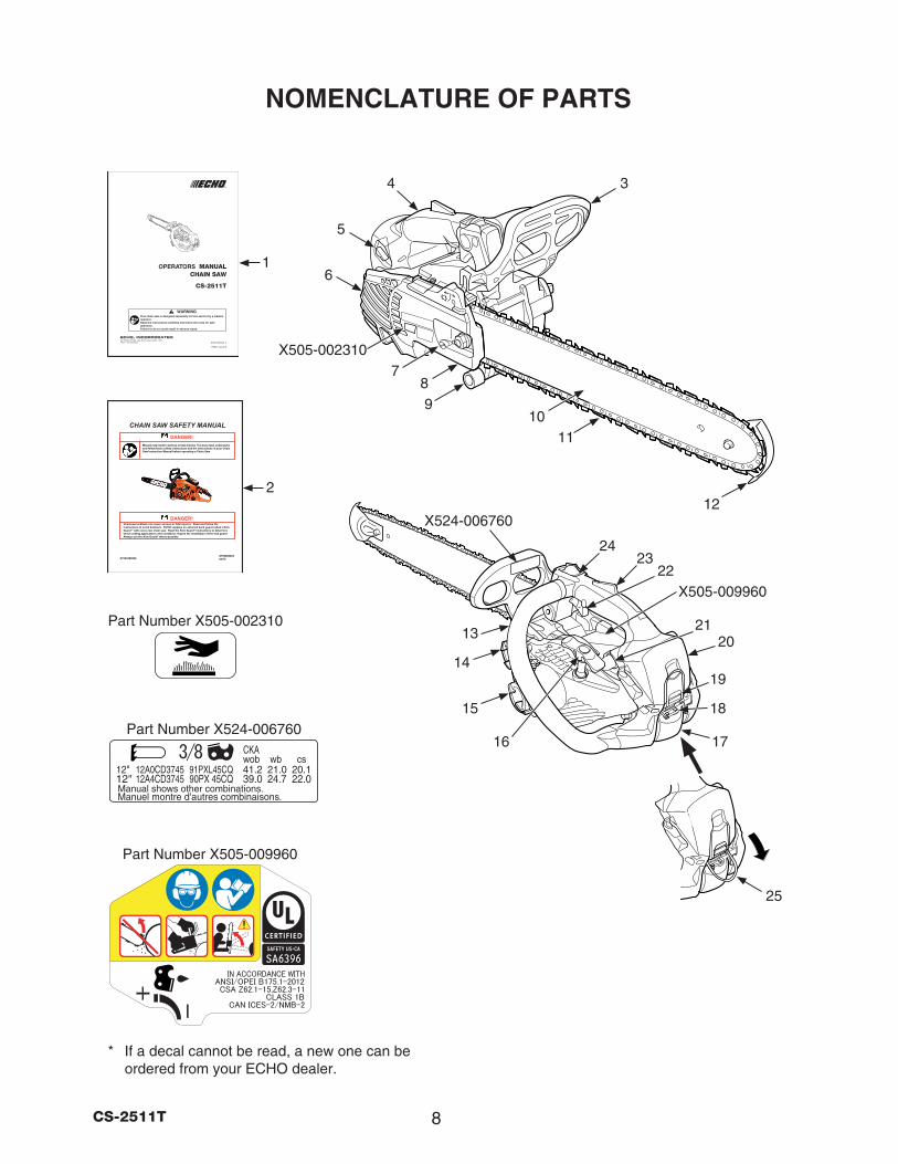
NOMENCLATURE OF PARTS
* If a decal cannot be read, a new one can be ordered from your ECHO dealer.
20
15
16
18
17
5
4
87
1011
13
3
2
1
9
22
6
23
21
X505-002310
X505-009960
24
1914
Part Number X505-002310
Part Number X505-009960
25
OPERATORS
12
Part Number X524-006760
X524-006760

9 CS-2511T
1. Operators manual - Included with unit.
Read before operation and keep for future
reference to learn proper, safe operating
techniques.
2. Safety manual - Describe operating and safety
instructions for this chain saw.
3. Front hand guard - Guard between the front
handle and the saw chain for protecting the
hand from injuries and aiding in control of the
chain saw if the hand slips off the handle.
This guard is used to lock the chain brake
which is to stop the saw chain rotation.
4. Rear handle (for the right hand) - Support
handle located on the top of the engine
housing.
5. Choke control knob - Device for enriching the
fuel/air mixture in the carburetor to aid cold
starting.
Also activates fast idle throttle latch.
6. Muffler cover - Cover the muffler not to make
operator touch to hot surface of muffler.
7. Chain tension adjuster - Device to adjust
chain tension.
8. Clutch cover - Protective cover to the guide
bar, saw chain, clutch and sprocket when
the chain saw is in use.
9. Chain catcher - A projection designed to
reduce the risk of the operator’s right hand
from being hit by a chain which has broken
or derailed from the guide bar during cutting.
10. Guide bar - The part that supports and guides
the saw chain.
11. Saw chain - Chain, serving as a cutting tool.
12. Bar tip guard - Anti-kickback device attached
on the bar nose.
NOMENCLATURE OF PARTS 13. Front handle (for the left hand) - Support
handle located at the left side of the engine
housing.
14. Fuel tank cap - For closing the fuel tank.
15. Oil tank cap - For closing the oil tank.
16. Starter handle - Pull handle slowly until starter
engages then quickly and firmly.
When engine starts, return handle slowly.
Do not let handle snap back or damage to
unit will occur.
17. Spark plug cover - Covers spark plug.
18. Spark plug cover lutch - Device for installing
the spark plug cover.
19. Cleaner cover lutch - Device for installing the
air cleaner cover.
20. Air cleaner cover - Covers air cleaner.
21. Purge pump - When starting engine, push
purge pump 3 or 4 times.
22. Throttle trigger - Device activated by the
operator’s finger, for controlling the engine
speed.
23. Throttle trigger lockout - A safety lever which
must be depressed before the throttle trigger
can be activated in order to prevent the
accidental operation of the throttle trigger.
24. Ignition switch - Device for connecting and
disconnecting the ignition system and thus
allowing the engine to be started or stopped.
25. Lifting hook - If working off the ground the
operator must be trained in safe climbing
techniques and use of all recommended
safety equipment.
10CS-2511T
OPERATOR SAFETYVIBRATION AND COLD• It is believed that a condition called Raynaud’s
Phenomenon, which affects the fingers of certain individuals, may be brought about by exposure to vibration and cold. Exposure to vibration and cold may cause tingling and burning followed by loss of color and numbness in the fingers. The following precautions are strongly recommended because the minimum exposure which might trigger the ailment is unknown.
• Keep your body warm, especially the head and neck, feet and ankles and hands and wrists.
• Maintain good blood circulation by performing vigorous arm exercises during frequent work breaks and also by not smoking.
• Limit the number of hours of operation. Try to fill each day with jobs where operating the chain saw, or other hand-held power equipment is not required.
• If you experience discomfort redness and swelling of the fingers, followed by whitening and loss of feeling, consult your physician before further exposing yourself to cold and vibration.
REPETITIVE STRESS INJURY• It is believed that over-using the muscles and
tendons of the finger, hands, arms and shoulders may cause soreness, swelling, numbness, weakness and extreme pain to the areas just mentioned. Certain repetitive hand activities may put you at a high risk for developing a repetitive stress injury (RSI).
• An extreme RSI condition is Carpal Tunnel Syndrome (CTS) which could occur when your wrist swells and squeezes a vital nerve that runs through the area. Some believe that prolonged exposure to vibration may contribute to CTS. CTS can cause severe pain for months or even years.
To reduce the risk of RSI/CTS, do the following:
• Avoid using your wrist in a bent, extended or twisted position.
• Take periodic breaks to minimize repetition and rest your hands.
• Reduce the speed and force in which you do the repetitive movement.
• Do exercises to strengthen hand and arm muscles.
• See a doctor if you feel tingling, numbness or pain in your fingers, hands, wrists or arms. The sooner RSI/CTS is diagnosed, the more likely permanent nerve and muscle damage can be prevented.
EYE AND HEARING PROTECTION• Wear eye protection goggles that meet ANSI
Z 87.1 requirements. Goggles meeting the requirements have the mark “Z 87” stamped on them.
• Wear hearing protection. If this guideline is not followed, hearing loss can occur. ECHO recommends wearing hearing protection at all times.
WEAR PROPER CLOTHING• Snug fitting durable clothing should be worn.
Pants should have long legs, do not wear shorts. Do not wear loose fitting clothing, scarves, neckties, jewelry or any item that may become tangled in surrounding growth or the chain saw itself.
• Wear shoes with non-skid soles. Do not wear open toed shoes or operate unit barefooted.
• Wear no-slip, heavy duty work gloves to improve your grip on the chain saw handles. The gloves also help reduce the transmission of machine vibration to your hands.
HOT HUMID WEATHER• Heavy protective clothing can increase operator
fatigue which may lead to heat stroke. Schedule heavy work for early morning, or late afternoon hours when temperatures are cooler.
AVOID HOT SURFACES• During operation, the muffler or catalytic muffler
and surrounding cover become hot. • Never suspend the saw on a lanyard with the
engine running. • Always use the saw from the right-hand side of
your body - never from the left side. • Always wear proper safety clothing to protect
your lower body from sharp saw chain and hot muffler.
• Always keep exhaust area clear of flammable debris during transportation or when storing, otherwise serious property damage or personal injury may result.
11 CS-2511T
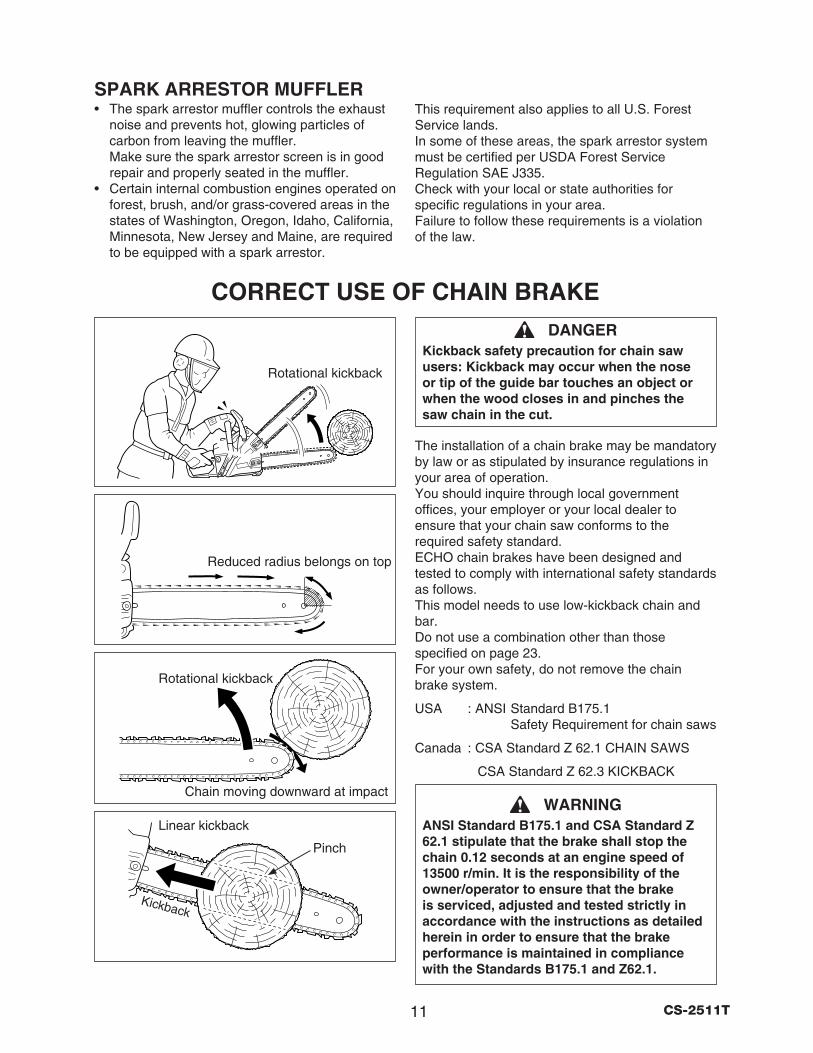
SPARK ARRESTOR MUFFLER• The spark arrestor muffler controls the exhaust
noise and prevents hot, glowing particles of carbon from leaving the muffler. Make sure the spark arrestor screen is in good repair and properly seated in the muffler.
• Certain internal combustion engines operated on forest, brush, and/or grass-covered areas in the states of Washington, Oregon, Idaho, California, Minnesota, New Jersey and Maine, are required to be equipped with a spark arrestor.
CORRECT USE OF CHAIN BRAKE
Linear kickback
Rotational kickback
Chain moving downward at impact
Rotational kickback
Reduced radius belongs on top
Pinch
Kickback
This requirement also applies to all U.S. Forest Service lands. In some of these areas, the spark arrestor system must be certified per USDA Forest Service Regulation SAE J335. Check with your local or state authorities for specific regulations in your area. Failure to follow these requirements is a violation of the law.
DANGERKickback safety precaution for chain saw users: Kickback may occur when the nose or tip of the guide bar touches an object or when the wood closes in and pinches the saw chain in the cut.
The installation of a chain brake may be mandatory by law or as stipulated by insurance regulations in your area of operation. You should inquire through local government offices, your employer or your local dealer to ensure that your chain saw conforms to the required safety standard. ECHO chain brakes have been designed and tested to comply with international safety standards as follows. This model needs to use low-kickback chain and bar. Do not use a combination other than those specified on page 23. For your own safety, do not remove the chain brake system.
USA : ANSI Standard B175.1 Safety Requirement for chain saws
Canada : CSA Standard Z 62.1 CHAIN SAWS
CSA Standard Z 62.3 KICKBACK
WARNINGANSI Standard B175.1 and CSA Standard Z 62.1 stipulate that the brake shall stop the chain 0.12 seconds at an engine speed of 13500 r/min. It is the responsibility of the owner/operator to ensure that the brake is serviced, adjusted and tested strictly in accordance with the instructions as detailed herein in order to ensure that the brake performance is maintained in compliance with the Standards B175.1 and Z62.1.
12CS-2511T
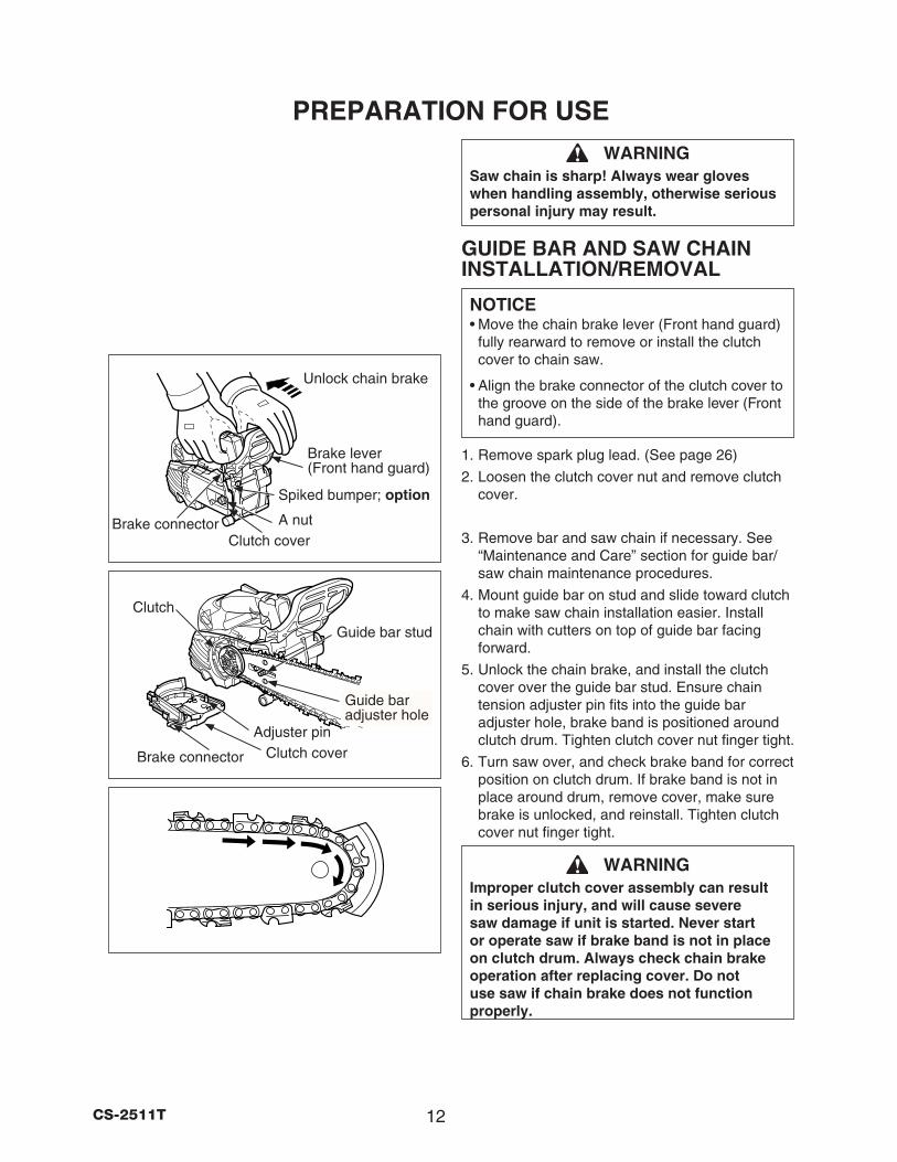
WARNINGSaw chain is sharp! Always wear gloves when handling assembly, otherwise serious personal injury may result.
GUIDE BAR AND SAW CHAIN INSTALLATION/REMOVAL
NOTICE• Move the chain brake lever (Front hand guard)
fully rearward to remove or install the clutch cover to chain saw.
• Align the brake connector of the clutch cover to the groove on the side of the brake lever (Front hand guard).
1. Remove spark plug lead. (See page 26)
2. Loosen the clutch cover nut and remove clutch cover.
3. Remove bar and saw chain if necessary. See “Maintenance and Care” section for guide bar/saw chain maintenance procedures.
4. Mount guide bar on stud and slide toward clutch to make saw chain installation easier. Install chain with cutters on top of guide bar facing forward.
5. Unlock the chain brake, and install the clutch cover over the guide bar stud. Ensure chain tension adjuster pin fits into the guide bar adjuster hole, brake band is positioned around clutch drum. Tighten clutch cover nut finger tight.
6. Turn saw over, and check brake band for correct position on clutch drum. If brake band is not in place around drum, remove cover, make sure brake is unlocked, and reinstall. Tighten clutch cover nut finger tight.
WARNINGImproper clutch cover assembly can result in serious injury, and will cause severe saw damage if unit is started. Never start or operate saw if brake band is not in place on clutch drum. Always check chain brake operation after replacing cover. Do not use saw if chain brake does not function properly.
Spiked bumper; option
PREPARATION FOR USE
Clutch cover
Brake lever(Front hand guard)
A nut
Unlock chain brake
Brake connector
Guide bar adjuster hole
Clutch coverAdjuster pin
Clutch
Guide bar stud
Brake connector
13 CS-2511T
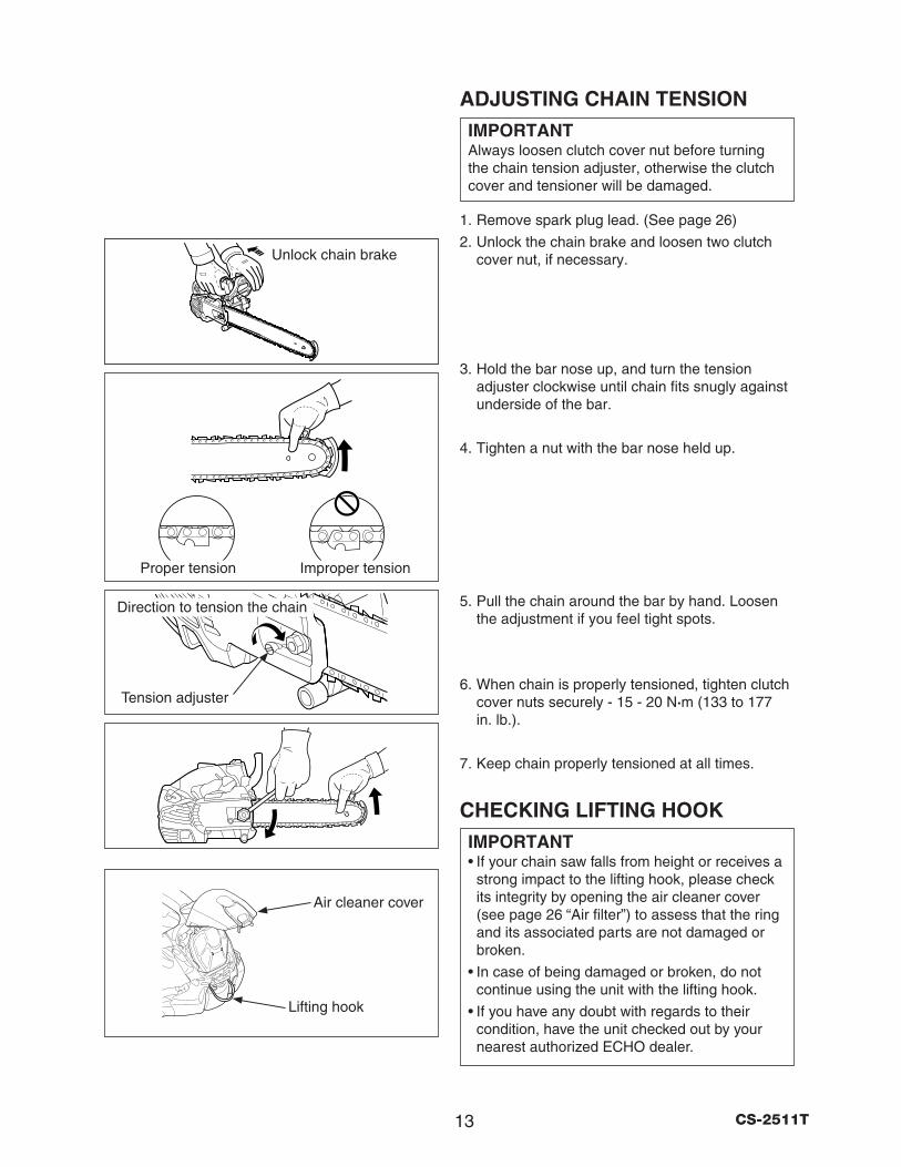
ADJUSTING CHAIN TENSIONIMPORTANTAlways loosen clutch cover nut before turning the chain tension adjuster, otherwise the clutch cover and tensioner will be damaged.
1. Remove spark plug lead. (See page 26)
2. Unlock the chain brake and loosen two clutch cover nut, if necessary.
3. Hold the bar nose up, and turn the tension adjuster clockwise until chain fits snugly against underside of the bar.
4. Tighten a nut with the bar nose held up.
5. Pull the chain around the bar by hand. Loosen the adjustment if you feel tight spots.
6. When chain is properly tensioned, tighten clutch cover nuts securely - 15 - 20 N·m (133 to 177 in. lb.).
7. Keep chain properly tensioned at all times.
CHECKING LIFTING HOOKIMPORTANT• If your chain saw falls from height or receives a
strong impact to the lifting hook, please check its integrity by opening the air cleaner cover (see page 26 “Air filter”) to assess that the ring and its associated parts are not damaged or broken.
• In case of being damaged or broken, do not continue using the unit with the lifting hook.
• If you have any doubt with regards to their condition, have the unit checked out by your nearest authorized ECHO dealer.
Unlock chain brake
Tension adjuster
Direction to tension the chain
Improper tensionProper tension
Air cleaner cover
Lifting hook
14CS-2511T
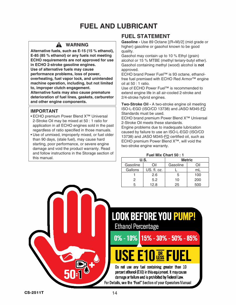
WARNINGAlternative fuels, such as E-15 (15 % ethanol), E-85 (85 % ethanol) or any fuels not meeting ECHO requirements are not approved for use in ECHO 2-stroke gasoline engines. Use of alternative fuels may cause performance problems, loss of power, overheating, fuel vapor lock, and unintended machine operation, including, but not limited to, improper clutch engagement. Alternative fuels may also cause premature deterioration of fuel lines, gaskets, carburetor and other engine components.
IMPORTANT • ECHO premium Power Blend X™ Universal
2-Stroke Oil may be mixed at 50 : 1 ratio for application in all ECHO engines sold in the past regardless of ratio specified in those manuals.
• Use of unmixed, improperly mixed, or fuel older than 90 days, (stale fuel), may cause hard starting, poor performance, or severe engine damage and void the product warranty. Read and follow instructions in the Storage section of this manual.
FUEL AND LUBRICANTFUEL STATEMENTGasoline - Use 89 Octane [(R+M)/2] (mid grade or higher) gasoline or gasohol known to be good quality. Gasohol may contain up to 10 % Ethyl (grain) alcohol or 15 % MTBE (methyl teriary-butyl ether). Gasohol containing methyl (wood) alcohol is not approved. ECHO brand Power Fuel™ is 93 octane, ethanol-free fuel premixed with ECHO Red Armor™ engine oil at 50 : 1 ratio. Use of ECHO Power Fuel™ is recommended to extend engine life in all air-cooled 2-stroke and 2/4-stroke hybrid engines.
Two-Stroke Oil - A two-stroke engine oil meeting ISO-L-EGD (ISO/CD 13738) and JASO M345-FD Standards must be used. ECHO brand premium Power Blend X™ Universal 2-Stroke Oil meets these standards. Engine problems due to inadequate lubrication caused by failure to use an ISO-L-EGD (ISO/CD 13738) and JASO M345-FD certified oil, such as ECHO premium Power Blend X™, will void the two-stroke engine warranty.
Fuel Mix Chart 50 : 1U.S. Metric
Gasoline Oil Gasoline OilGallons US. fl. oz. L mL
1 2.6 5 1002 5.2 10 2005 12.8 25 500
15 CS-2511T
HANDLING FUELMixing Instructions - 1. Fill an approved fuel container with half of the
required amount of gasoline.
2. Add the proper amount of two-stroke oil to gasoline.
3. Close container and shake to mix oil with gasoline.
4. Add remaining gasoline, close fuel container, and remix.
IMPORTANT • Spilled fuel is a leading cause of hydrocarbon
emissions. Some states may require the use of automatic fuel shut-off containers to reduce fuel spillage.
• Stored fuel ages. Do not mix more fuel than you expect to use in thirty (30) days, ninety (90) days when a fuel stabilizer is added.
• Stored two-stroke fuel may separate. Always shake fuel container thoroughly before each use.
After Use - Do not store a unit with fuel in its tank. Leaks can occur. Return unused fuel to an approved fuel storage container.
Storage - Fuel storage laws vary by locality. Contact your local government for the laws affecting your area. As a precaution, store fuel in an approved, airtight container. Store in a well-ventilated, unoccupied building, away from sparks and flames.
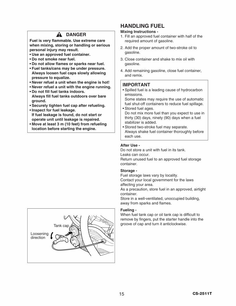
Fueling - When fuel tank cap or oil tank cap is difficult to remove by fingers, put the starter handle into the groove of cap and turn it anticlockwise.
DANGERFuel is very flammable. Use extreme care when mixing, storing or handling or serious personal injury may result. • Use an approved fuel container. • Do not smoke near fuel. • Do not allow flames or sparks near fuel. • Fuel tanks/cans may be under pressure.
Always loosen fuel caps slowly allowing pressure to equalize.
• Never refuel a unit when the engine is hot! • Never refuel a unit with the engine running. • Do not fill fuel tanks indoors.
Always fill fuel tanks outdoors over bare ground.
• Securely tighten fuel cap after refueling. • Inspect for fuel leakage.
If fuel leakage is found, do not start or operate unit until leakage is repaired.
• Move at least 3 m (10 feet) from refueling location before starting the engine.
Tank cap
Loosening direction
16CS-2511T
EMISSION DATAEMISSION CONTROL(EXHAUST and EVAPORATIVE) EPA 2010 and/or C.A.R.B. TIER IIIThe emission control system for the engine is EM/TWC (Engine Modification and 3-way Catalyst) and for the fuel tank the Control System is EVAP (Evaporative Emissions) or N (for nylon tank). Evaporative emission may be applicable to California models only.
An Emission Control Label is located on the engine. (This is an example only, information on label varies by engine family).
PRODUCT EMISSION DURABILITY (EMISSION COMPLIANCE PERIOD)The 300 hours emission compliance period is the time span selected by the manufacturer certifying the engine emissions output meets applicable emissions regulations, provided that approved maintenance procedures are followed as listed in the Maintenance Section of this manual.
EMISSION CONTROL INFORMATIONENGINE FAMILY: #EHXS.xxxxxx DISPLACEMENT: 25.0 cc EMISSION COMPLIANCE PERIOD: 300 Hours THIS ENGINE MEETS * * * * U.S. EPA EXH/EVP & CALIFORNIA EXH/EVP EMISSION REGULATIONS FOR S.O.R.E. REFER TO OWNER’S MANUAL FOR MAINTENANCE SPECIFICATIONS AND ADJUSTMENTS.
* * * ? ? ? ?
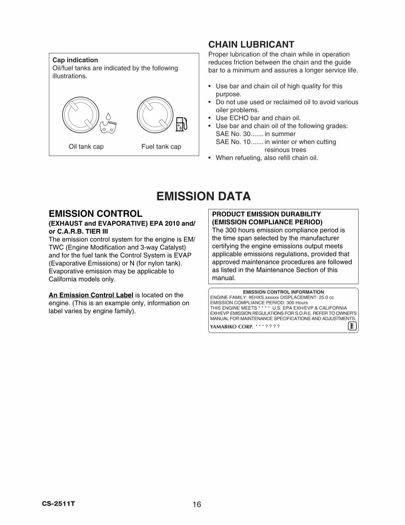
Oil tank cap
CHAIN LUBRICANTProper lubrication of the chain while in operation reduces friction between the chain and the guide bar to a minimum and assures a longer service life.
• Use bar and chain oil of high quality for this purpose.
• Do not use used or reclaimed oil to avoid various oiler problems.
• Use ECHO bar and chain oil.• Use bar and chain oil of the following grades:
SAE No. 30 ....... in summerSAE No. 10 ....... in winter or when cutting
resinous trees• When refueling, also refill chain oil.
Fuel tank cap
Cap indicationOil/fuel tanks are indicated by the following illustrations.
17 CS-2511T
OPERATION
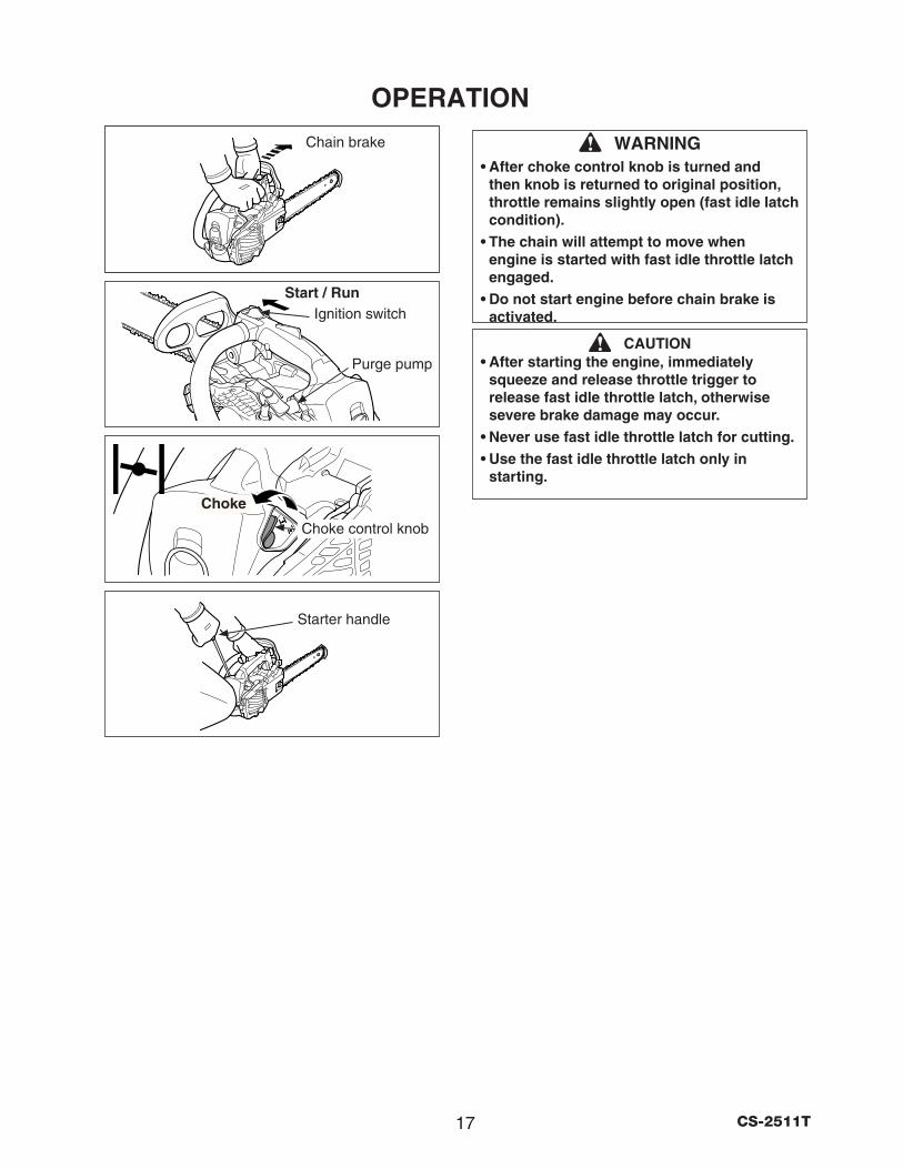
Start / RunIgnition switch
Chain brake
Starter handle
Purge pump
Choke
Choke control knob
WARNING• After choke control knob is turned and
then knob is returned to original position, throttle remains slightly open (fast idle latch condition).
• The chain will attempt to move when engine is started with fast idle throttle latch engaged.
• Do not start engine before chain brake is activated.
CAUTION• After starting the engine, immediately
squeeze and release throttle trigger to release fast idle throttle latch, otherwise severe brake damage may occur.
• Never use fast idle throttle latch for cutting. • Use the fast idle throttle latch only in
starting.
18CS-2511T
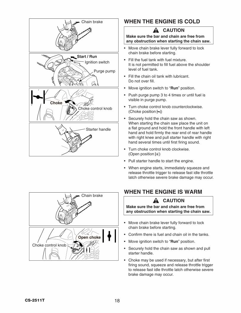
WHEN THE ENGINE IS COLD
CAUTIONMake sure the bar and chain are free from any obstruction when starting the chain saw.
• Move chain brake lever fully forward to lock chain brake before starting.
• Fill the fuel tank with fuel mixture. It is not permitted to fill fuel above the shoulder level of fuel tank.
• Fill the chain oil tank with lubricant. Do not over fill.
• Move ignition switch to “Run” position.
• Push purge pump 3 to 4 times or until fuel is visible in purge pump.
• Turn choke control knob counterclockwise. (Choke position )
• Securely hold the chain saw as shown. When starting the chain saw place the unit on a flat ground and hold the front handle with left hand and hold firmly the rear end of rear handle with right knee and pull starter handle with right hand several times until first firing sound.
• Turn choke control knob clockwise. (Open position )
• Pull starter handle to start the engine.
• When engine starts, immediately squeeze and release throttle trigger to release fast idle throttle latch otherwise severe brake damage may occur.
WHEN THE ENGINE IS WARM
CAUTIONMake sure the bar and chain are free from any obstruction when starting the chain saw.
• Move chain brake lever fully forward to lock chain brake before starting.
• Confirm there is fuel and chain oil in the tanks.
• Move ignition switch to “Run” position.
• Securely hold the chain saw as shown and pull starter handle.
• Choke may be used if necessary, but after first firing sound, squeeze and release throttle trigger to release fast idle throttle latch otherwise severe brake damage may occur.
Open choke
Choke control knob
Start / RunIgnition switch
Chain brake
Starter handle
Purge pump
ChokeChoke control knob
Chain brake
19 CS-2511T
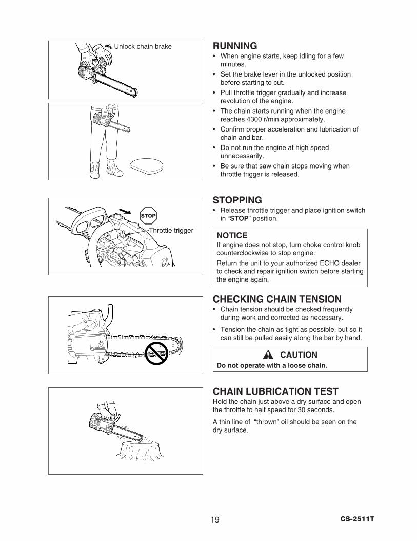
RUNNING• When engine starts, keep idling for a few
minutes.
• Set the brake lever in the unlocked position before starting to cut.
• Pull throttle trigger gradually and increase revolution of the engine.
• The chain starts running when the engine reaches 4300 r/min approximately.
• Confirm proper acceleration and lubrication of chain and bar.
• Do not run the engine at high speed unnecessarily.
• Be sure that saw chain stops moving when throttle trigger is released.
STOPPING• Release throttle trigger and place ignition switch
in “STOP” position.
NOTICEIf engine does not stop, turn choke control knob counterclockwise to stop engine.
Return the unit to your authorized ECHO dealer to check and repair ignition switch before starting the engine again.
CHECKING CHAIN TENSION• Chain tension should be checked frequently
during work and corrected as necessary.
• Tension the chain as tight as possible, but so it can still be pulled easily along the bar by hand.
CAUTIONDo not operate with a loose chain.
CHAIN LUBRICATION TESTHold the chain just above a dry surface and open the throttle to half speed for 30 seconds.
A thin line of “thrown” oil should be seen on the dry surface.
Throttle trigger
Unlock chain brake
20CS-2511T
CUTTING INSTRUCTIONGENERAL
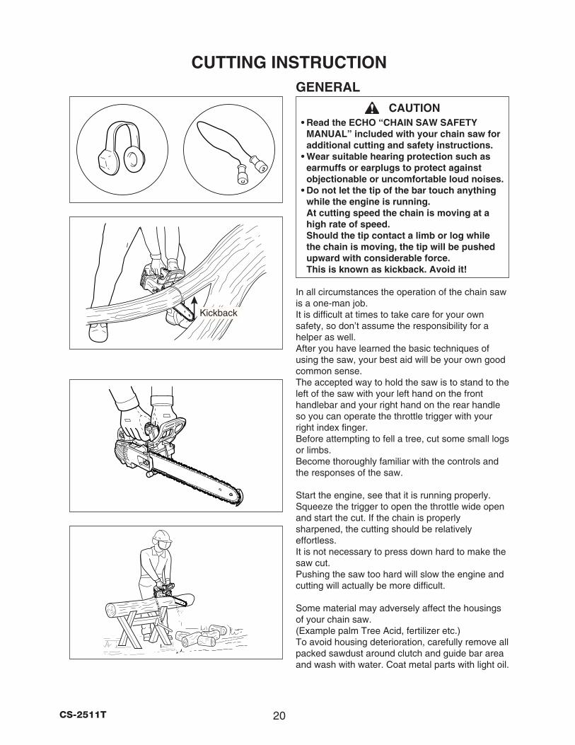
CAUTION• Read the ECHO “CHAIN SAW SAFETY
MANUAL” included with your chain saw for additional cutting and safety instructions.
• Wear suitable hearing protection such as earmuffs or earplugs to protect against objectionable or uncomfortable loud noises.
• Do not let the tip of the bar touch anything while the engine is running. At cutting speed the chain is moving at a high rate of speed. Should the tip contact a limb or log while the chain is moving, the tip will be pushed upward with considerable force. This is known as kickback. Avoid it!
In all circumstances the operation of the chain saw is a one-man job. It is difficult at times to take care for your own safety, so don’t assume the responsibility for a helper as well. After you have learned the basic techniques of using the saw, your best aid will be your own good common sense. The accepted way to hold the saw is to stand to the left of the saw with your left hand on the front handlebar and your right hand on the rear handle so you can operate the throttle trigger with your right index finger. Before attempting to fell a tree, cut some small logs or limbs. Become thoroughly familiar with the controls and the responses of the saw.
Start the engine, see that it is running properly. Squeeze the trigger to open the throttle wide open and start the cut. If the chain is properly sharpened, the cutting should be relatively effortless. It is not necessary to press down hard to make the saw cut. Pushing the saw too hard will slow the engine and cutting will actually be more difficult.
Some material may adversely affect the housings of your chain saw. (Example palm Tree Acid, fertilizer etc.) To avoid housing deterioration, carefully remove all packed sawdust around clutch and guide bar area and wash with water. Coat metal parts with light oil.
Kickback
21 CS-2511T
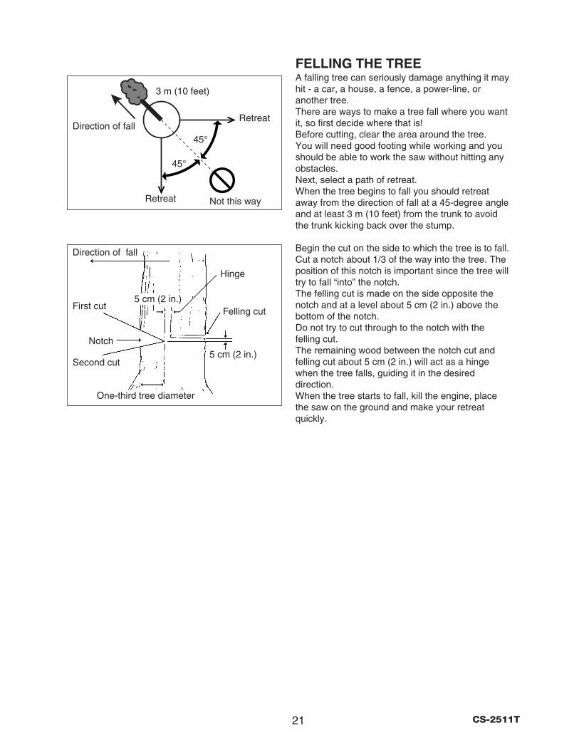
FELLING THE TREEA falling tree can seriously damage anything it may hit - a car, a house, a fence, a power-line, or another tree. There are ways to make a tree fall where you want it, so first decide where that is! Before cutting, clear the area around the tree. You will need good footing while working and you should be able to work the saw without hitting any obstacles. Next, select a path of retreat. When the tree begins to fall you should retreat away from the direction of fall at a 45-degree angle and at least 3 m (10 feet) from the trunk to avoid the trunk kicking back over the stump.
Begin the cut on the side to which the tree is to fall. Cut a notch about 1/3 of the way into the tree. The position of this notch is important since the tree will try to fall “into” the notch. The felling cut is made on the side opposite the notch and at a level about 5 cm (2 in.) above the bottom of the notch. Do not try to cut through to the notch with the felling cut. The remaining wood between the notch cut and felling cut about 5 cm (2 in.) will act as a hinge when the tree falls, guiding it in the desired direction. When the tree starts to fall, kill the engine, place the saw on the ground and make your retreat quickly.
Felling cut
Hinge
Direction of fall
First cut
Notch
Second cut
One-third tree diameter
Direction of fall
5 cm (2 in.)
5 cm (2 in.)
45°
45°
Not this way
Retreat
Retreat
3 m (10 feet)
22CS-2511T
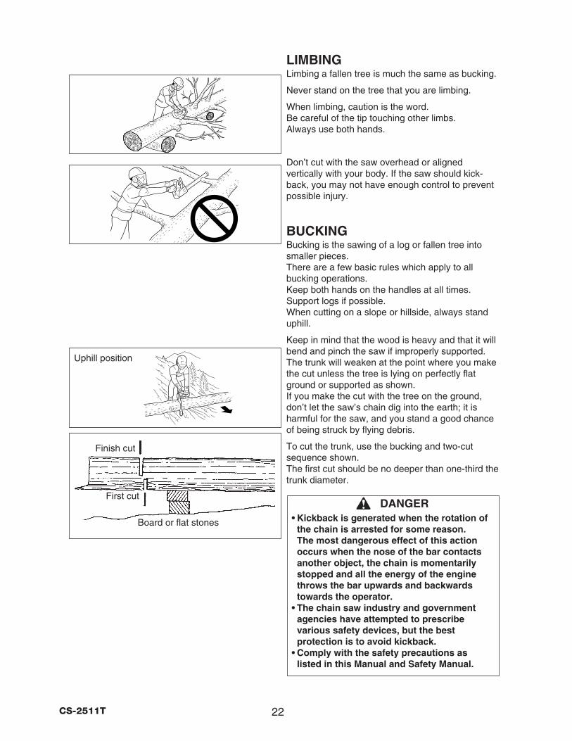
LIMBINGLimbing a fallen tree is much the same as bucking.
Never stand on the tree that you are limbing.
When limbing, caution is the word. Be careful of the tip touching other limbs. Always use both hands.
Don’t cut with the saw overhead or aligned vertically with your body. If the saw should kick-back, you may not have enough control to prevent possible injury.
BUCKINGBucking is the sawing of a log or fallen tree into smaller pieces. There are a few basic rules which apply to all bucking operations. Keep both hands on the handles at all times. Support logs if possible. When cutting on a slope or hillside, always stand uphill.
Keep in mind that the wood is heavy and that it will bend and pinch the saw if improperly supported. The trunk will weaken at the point where you make the cut unless the tree is lying on perfectly flat ground or supported as shown. If you make the cut with the tree on the ground, don’t let the saw’s chain dig into the earth; it is harmful for the saw, and you stand a good chance of being struck by flying debris.
To cut the trunk, use the bucking and two-cut sequence shown. The first cut should be no deeper than one-third the trunk diameter.
DANGER• Kickback is generated when the rotation of
the chain is arrested for some reason. The most dangerous effect of this action occurs when the nose of the bar contacts another object, the chain is momentarily stopped and all the energy of the engine throws the bar upwards and backwards towards the operator.
• The chain saw industry and government agencies have attempted to prescribe various safety devices, but the best protection is to avoid kickback.
• Comply with the safety precautions as listed in this Manual and Safety Manual.
Uphill position
Finish cut
First cut
Board or flat stones
23 CS-2511T
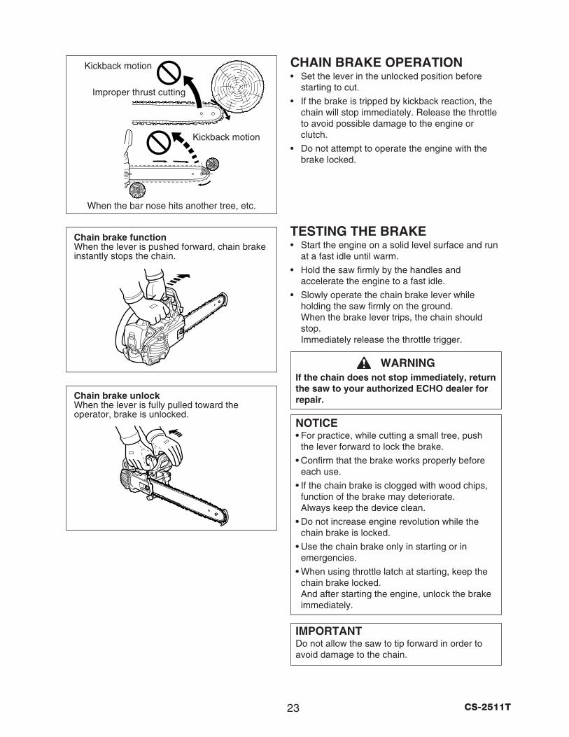
Chain brake functionWhen the lever is pushed forward, chain brake instantly stops the chain.
Chain brake unlockWhen the lever is fully pulled toward the operator, brake is unlocked.
When the bar nose hits another tree, etc.
Improper thrust cutting
CHAIN BRAKE OPERATION• Set the lever in the unlocked position before
starting to cut.
• If the brake is tripped by kickback reaction, the chain will stop immediately. Release the throttle to avoid possible damage to the engine or clutch.
• Do not attempt to operate the engine with the brake locked.
TESTING THE BRAKE• Start the engine on a solid level surface and run
at a fast idle until warm.
• Hold the saw firmly by the handles and accelerate the engine to a fast idle.
• Slowly operate the chain brake lever while holding the saw firmly on the ground. When the brake lever trips, the chain should stop. Immediately release the throttle trigger.
WARNINGIf the chain does not stop immediately, return the saw to your authorized ECHO dealer for repair.
NOTICE• For practice, while cutting a small tree, push
the lever forward to lock the brake.
• Confirm that the brake works properly before each use.
• If the chain brake is clogged with wood chips, function of the brake may deteriorate. Always keep the device clean.
• Do not increase engine revolution while the chain brake is locked.
• Use the chain brake only in starting or in emergencies.
• When using throttle latch at starting, keep the chain brake locked. And after starting the engine, unlock the brake immediately.
IMPORTANTDo not allow the saw to tip forward in order to avoid damage to the chain.
Kickback motion
Kickback motion
24CS-2511T
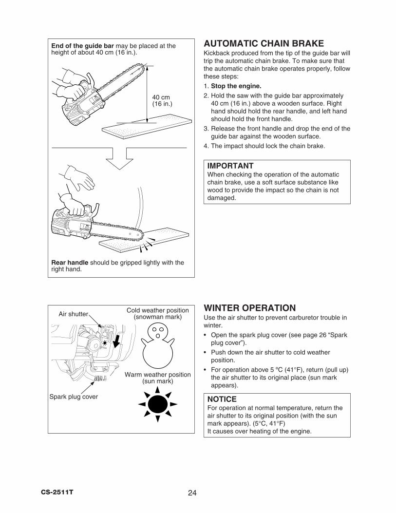
End of the guide bar may be placed at the height of about 40 cm (16 in.).
40 cm(16 in.)
Rear handle should be gripped lightly with the right hand.
AUTOMATIC CHAIN BRAKEKickback produced from the tip of the guide bar will trip the automatic chain brake. To make sure that the automatic chain brake operates properly, follow these steps:
1. Stop the engine. 2. Hold the saw with the guide bar approximately
40 cm (16 in.) above a wooden surface. Right hand should hold the rear handle, and left hand should hold the front handle.
3. Release the front handle and drop the end of the guide bar against the wooden surface.
4. The impact should lock the chain brake.
IMPORTANTWhen checking the operation of the automatic chain brake, use a soft surface substance like wood to provide the impact so the chain is not damaged.
WINTER OPERATIONUse the air shutter to prevent carburetor trouble in winter.
• Open the spark plug cover (see page 26 “Spark plug cover”).
• Push down the air shutter to cold weather position.
• For operation above 5 ºC (41°F), return (pull up) the air shutter to its original place (sun mark appears).
NOTICEFor operation at normal temperature, return the air shutter to its original position (with the sun mark appears). (5°C, 41°F) It causes over heating of the engine.
Warm weather position (sun mark)
Cold weather position (snowman mark)Air shutter
Spark plug cover
25 CS-2511T
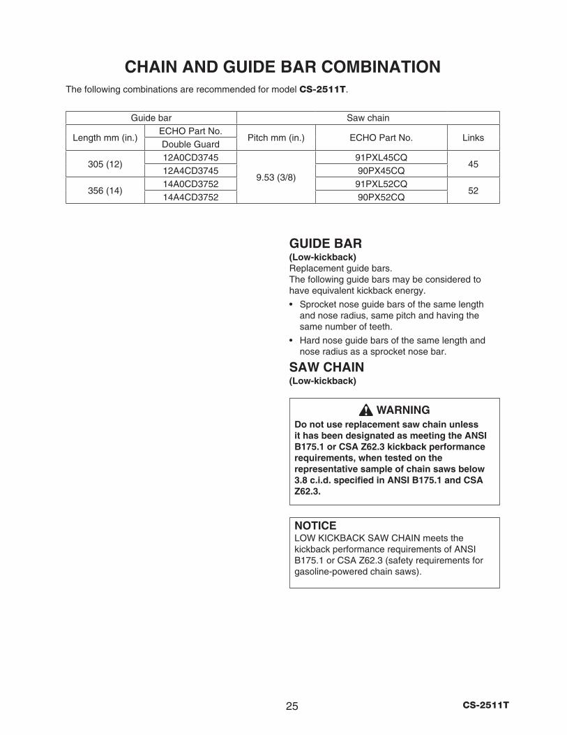
CHAIN AND GUIDE BAR COMBINATIONThe following combinations are recommended for model CS-2511T.
GUIDE BAR(Low-kickback)Replacement guide bars. The following guide bars may be considered to have equivalent kickback energy.
• Sprocket nose guide bars of the same length and nose radius, same pitch and having the same number of teeth.
• Hard nose guide bars of the same length and nose radius as a sprocket nose bar.
SAW CHAIN(Low-kickback)
WARNINGDo not use replacement saw chain unless it has been designated as meeting the ANSI B175.1 or CSA Z62.3 kickback performance requirements, when tested on the representative sample of chain saws below 3.8 c.i.d. specified in ANSI B175.1 and CSA Z62.3.
NOTICELOW KICKBACK SAW CHAIN meets the kickback performance requirements of ANSI B175.1 or CSA Z62.3 (safety requirements for gasoline-powered chain saws).
Guide bar Saw chain
Length mm (in.)ECHO Part No.
Pitch mm (in.) ECHO Part No. LinksDouble Guard
305 (12)12A0CD3745
9.53 (3/8)
91PXL45CQ45
12A4CD3745 90PX45CQ
356 (14)14A0CD3752 91PXL52CQ
5214A4CD3752 90PX52CQ
26CS-2511T
MAINTENANCE AND CARE
IMPORTANTTime intervals shown are maximum. Actual use and your experience will determine the frequency of required maintenance.
Your ECHO chain saw is designed to provide many hours of trouble free service. Regular scheduled maintenance will help your chain saw achieve that goal. If you are unsure or are not equipped with the necessary tools, you may want to take your unit to an ECHO Service Dealer for maintenance. To help you decide whether you want to DO-IT-YOURSELF or have the ECHO Dealer do it, each maintenance task has been graded. If the task is not listed ask your ECHO dealer for repairs.
SKILL LEVELSLevel 1 = Easy to do. Most required tools come
with unit. Level 2 = Moderate difficulty. Some specialized
tools may be required.
Click HERE or go to http://www.echo-usa.com/products/maintenance-kit for information on Main-tenance Kits.
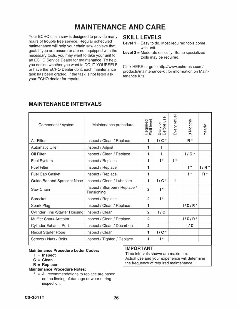
MAINTENANCE INTERVALS
Maintenance Procedure Letter Codes: I = Inspect C = Clean R = Replace
Maintenance Procedure Notes: * = All recommendations to replace are based
on the finding of damage or wear during inspection.
Component / system Maintenance procedure
Req
uire
d S
kill
leve
l
Dai
ly o
r B
efor
e us
e
Eve
ry r
efue
l
3 M
onth
s
Yea
rly
Air Filter Inspect / Clean / Replace 1 I / C * R *
Automatic Oiler Inspect / Adjust 1 I
Oil Filter Inspect / Clean / Replace 1 I I / C *
Fuel System Inspect / Replace 1 I * I *
Fuel Filter Inspect / Replace 1 I * I / R *
Fuel Cap Gasket Inspect / Replace 1 I * R *
Guide Bar and Sprocket Nose Inspect / Clean / Lubricate 1 I / C * I
Saw Chain Inspect / Sharpen / Replace / Tensioning
2 I *
Sprocket Inspect / Replace 2 I *
Spark Plug Inspect / Clean / Replace 1 I / C / R *
Cylinder Fins /Starter Housing Inspect / Clean 2 I / C
Muffler Spark Arrestor Inspect / Clean / Replace 2 I / C / R *
Cylinder Exhaust Port Inspect / Clean / Decarbon 2 I / C
Recoil Starter Rope Inspect / Clean 1 I / C *
Screws / Nuts / Bolts Inspect / Tighten / Replace 1 I *
27 CS-2511T
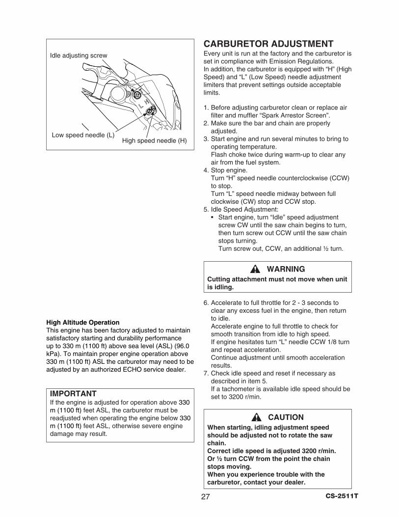
CARBURETOR ADJUSTMENTEvery unit is run at the factory and the carburetor is set in compliance with Emission Regulations. In addition, the carburetor is equipped with “H” (High Speed) and “L” (Low Speed) needle adjustment limiters that prevent settings outside acceptable limits.
1. Before adjusting carburetor clean or replace air filter and muffler “Spark Arrestor Screen”.
2. Make sure the bar and chain are properly adjusted.
3. Start engine and run several minutes to bring to operating temperature. Flash choke twice during warm-up to clear any air from the fuel system.
4. Stop engine. Turn “H” speed needle counterclockwise (CCW) to stop. Turn “L” speed needle midway between full clockwise (CW) stop and CCW stop.
5. Idle Speed Adjustment: • Start engine, turn “Idle” speed adjustment
screw CW until the saw chain begins to turn, then turn screw out CCW until the saw chain stops turning. Turn screw out, CCW, an additional ½ turn.
WARNINGCutting attachment must not move when unit is idling.
6. Accelerate to full throttle for 2 - 3 seconds to clear any excess fuel in the engine, then return to idle. Accelerate engine to full throttle to check for smooth transition from idle to high speed. If engine hesitates turn “L” needle CCW 1/8 turn and repeat acceleration. Continue adjustment until smooth acceleration results.
7. Check idle speed and reset if necessary as described in item 5. If a tachometer is available idle speed should be set to 3200 r/min.
CAUTIONWhen starting, idling adjustment speed should be adjusted not to rotate the saw chain. Correct idle speed is adjusted 3200 r/min. Or ½ turn CCW from the point the chain stops moving. When you experience trouble with the carburetor, contact your dealer.
Idle adjusting screw
Low speed needle (L)High speed needle (H)
High Altitude OperationThis engine has been factory adjusted to maintain satisfactory starting and durability performance up to 330 m (1100 ft) above sea level (ASL) (96.0 kPa). To maintain proper engine operation above 330 m (1100 ft) ASL the carburetor may need to be adjusted by an authorized ECHO service dealer.
IMPORTANTIf the engine is adjusted for operation above 330 m (1100 ft) feet ASL, the carburetor must be readjusted when operating the engine below 330 m (1100 ft) feet ASL, otherwise severe engine damage may result.
28CS-2511T
0.6 - 0.7 mm (0.024-0.026 in.)
Cleaner cover latch
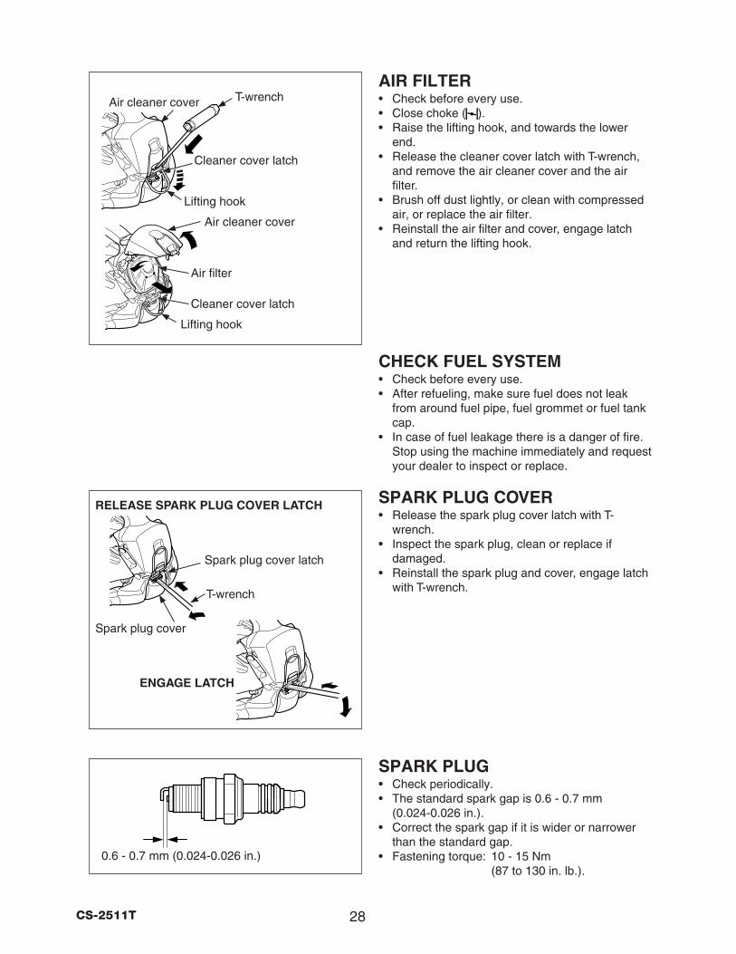
T-wrenchAir cleaner cover
AIR FILTER• Check before every use. • Close choke ( ). • Raise the lifting hook, and towards the lower
end. • Release the cleaner cover latch with T-wrench,
and remove the air cleaner cover and the air filter.
• Brush off dust lightly, or clean with compressed air, or replace the air filter.
• Reinstall the air filter and cover, engage latch and return the lifting hook.
CHECK FUEL SYSTEM• Check before every use. • After refueling, make sure fuel does not leak
from around fuel pipe, fuel grommet or fuel tank cap.
• In case of fuel leakage there is a danger of fire. Stop using the machine immediately and request your dealer to inspect or replace.
SPARK PLUG COVER• Release the spark plug cover latch with T-
wrench. • Inspect the spark plug, clean or replace if
damaged. • Reinstall the spark plug and cover, engage latch
with T-wrench.
SPARK PLUG• Check periodically. • The standard spark gap is 0.6 - 0.7 mm
(0.024-0.026 in.). • Correct the spark gap if it is wider or narrower
than the standard gap. • Fastening torque: 10 - 15 Nm
(87 to 130 in. lb.).
Air filter
Lifting hook
Lifting hook
Cleaner cover latch
Air cleaner cover
Spark plug cover latch
T-wrench
Spark plug cover
RELEASE SPARK PLUG COVER LATCH
ENGAGE LATCH
29 CS-2511T
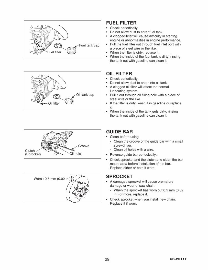
Oil filter
Fuel filter
Oil tank cap
Fuel tank cap
FUEL FILTER• Check periodically. • Do not allow dust to enter fuel tank. • A clogged filter will cause difficulty in starting
engine or abnormalities in engine performance. • Pull the fuel filter out through fuel inlet port with
a piece of steel wire or the like. • When the filter is dirty, replace it. • When the inside of the fuel tank is dirty, rinsing
the tank out with gasoline can clean it.
OIL FILTER• Check periodically. • Do not allow dust to enter into oil tank. • A clogged oil filter will affect the normal
lubricating system. • Pull it out through oil filling hole with a piece of
steel wire or the like. • If the filter is dirty, wash it in gasoline or replace
it. • When the inside of the tank gets dirty, rinsing
the tank out with gasoline can clean it.
GUIDE BAR• Clean before using.
- Clean the groove of the guide bar with a small screwdriver.
- Clean oil holes with a wire.
• Reverse guide bar periodically.
• Check sprocket and the clutch and clean the bar mount area before installation of the bar. Replace either or both if worn.
SPROCKET• A damaged sprocket will cause premature
damage or wear of saw chain. - When the sprocket has worn out 0.5 mm (0.02
in.) or more, replace it.
• Check sprocket when you install new chain. Replace it if worn.
Worn : 0.5 mm (0.02 in.)
Groove
Oil holeClutch (Sprocket)
30CS-2511T
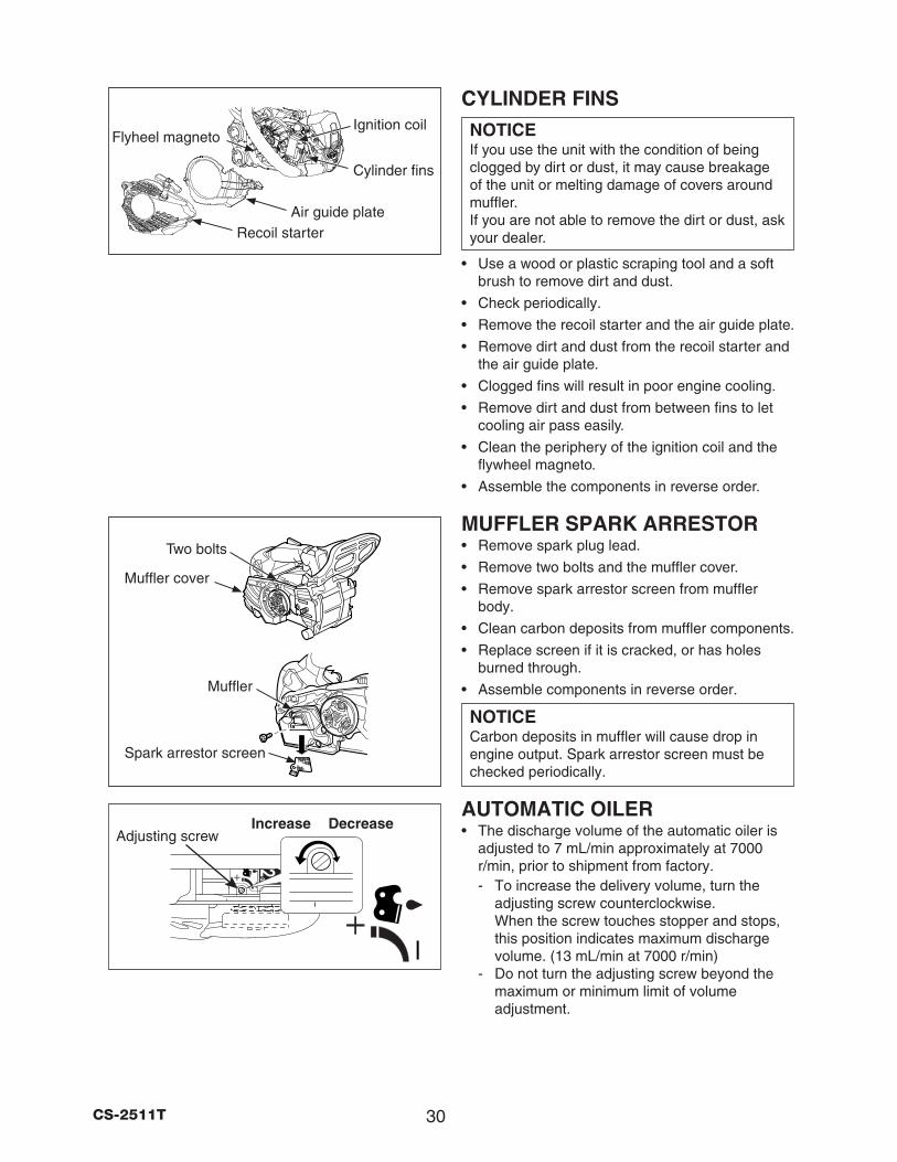
CYLINDER FINSNOTICEIf you use the unit with the condition of being clogged by dirt or dust, it may cause breakage of the unit or melting damage of covers around muffler. If you are not able to remove the dirt or dust, ask your dealer.
• Use a wood or plastic scraping tool and a soft brush to remove dirt and dust.
• Check periodically.
• Remove the recoil starter and the air guide plate.
• Remove dirt and dust from the recoil starter and the air guide plate.
• Clogged fins will result in poor engine cooling.
• Remove dirt and dust from between fins to let cooling air pass easily.
• Clean the periphery of the ignition coil and the flywheel magneto.
• Assemble the components in reverse order.
MUFFLER SPARK ARRESTOR• Remove spark plug lead.
• Remove two bolts and the muffler cover.
• Remove spark arrestor screen from muffler body.
• Clean carbon deposits from muffler components.
• Replace screen if it is cracked, or has holes burned through.
• Assemble components in reverse order.
NOTICECarbon deposits in muffler will cause drop in engine output. Spark arrestor screen must be checked periodically.
AUTOMATIC OILER• The discharge volume of the automatic oiler is
adjusted to 7 mL/min approximately at 7000 r/min, prior to shipment from factory. - To increase the delivery volume, turn the
adjusting screw counterclockwise. When the screw touches stopper and stops, this position indicates maximum discharge volume. (13 mL/min at 7000 r/min)
- Do not turn the adjusting screw beyond the maximum or minimum limit of volume adjustment.
Ignition coil
Spark arrestor screen
Muffler
Muffler cover
DecreaseIncreaseAdjusting screw
Two bolts
Flyheel magneto
Cylinder fins
Air guide plateRecoil starter
31 CS-2511T
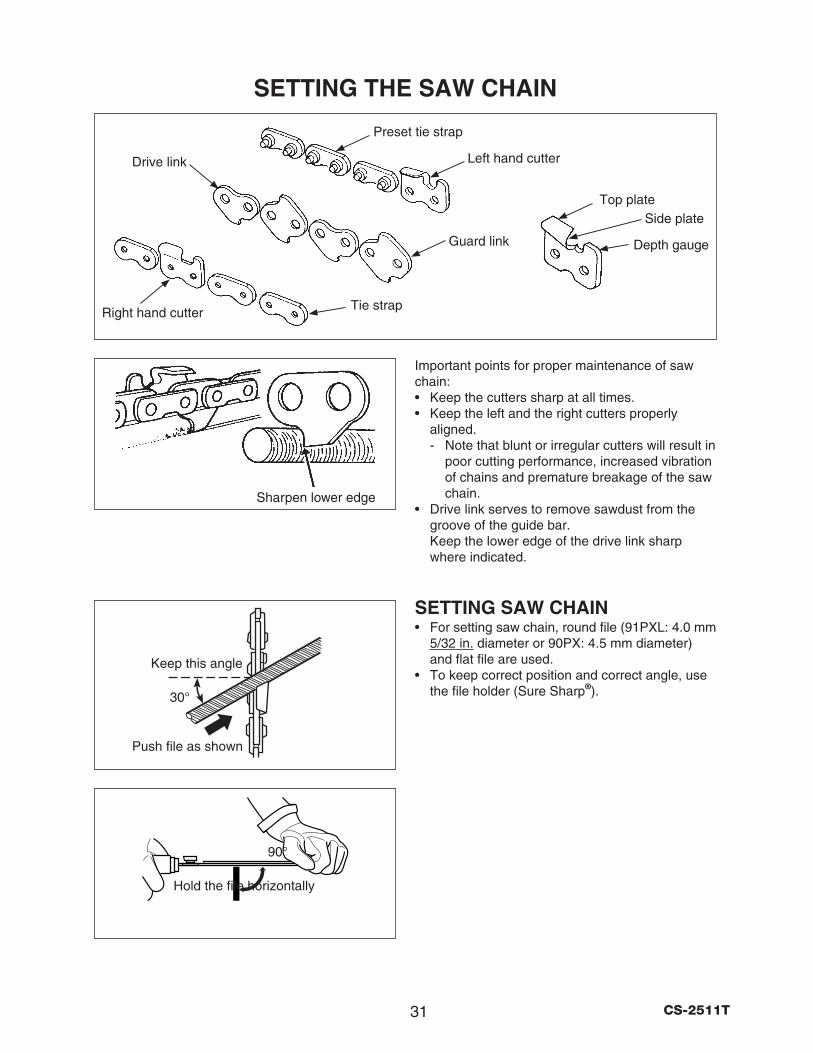
SETTING THE SAW CHAIN
Sharpen lower edge
Drive link
Tie strapRight hand cutter
Preset tie strap
Left hand cutter
Guard link
Top plateSide plate
Depth gauge
Hold the file horizontally
90°
Important points for proper maintenance of saw chain: • Keep the cutters sharp at all times. • Keep the left and the right cutters properly
aligned. - Note that blunt or irregular cutters will result in
poor cutting performance, increased vibration of chains and premature breakage of the saw chain.
• Drive link serves to remove sawdust from the groove of the guide bar. Keep the lower edge of the drive link sharp where indicated.
SETTING SAW CHAIN• For setting saw chain, round file (91PXL: 4.0 mm
5/32 in. diameter or 90PX: 4.5 mm diameter) and flat file are used.
• To keep correct position and correct angle, use the file holder (Sure Sharp®). 30°
Push file as shown
Keep this angle
32CS-2511T
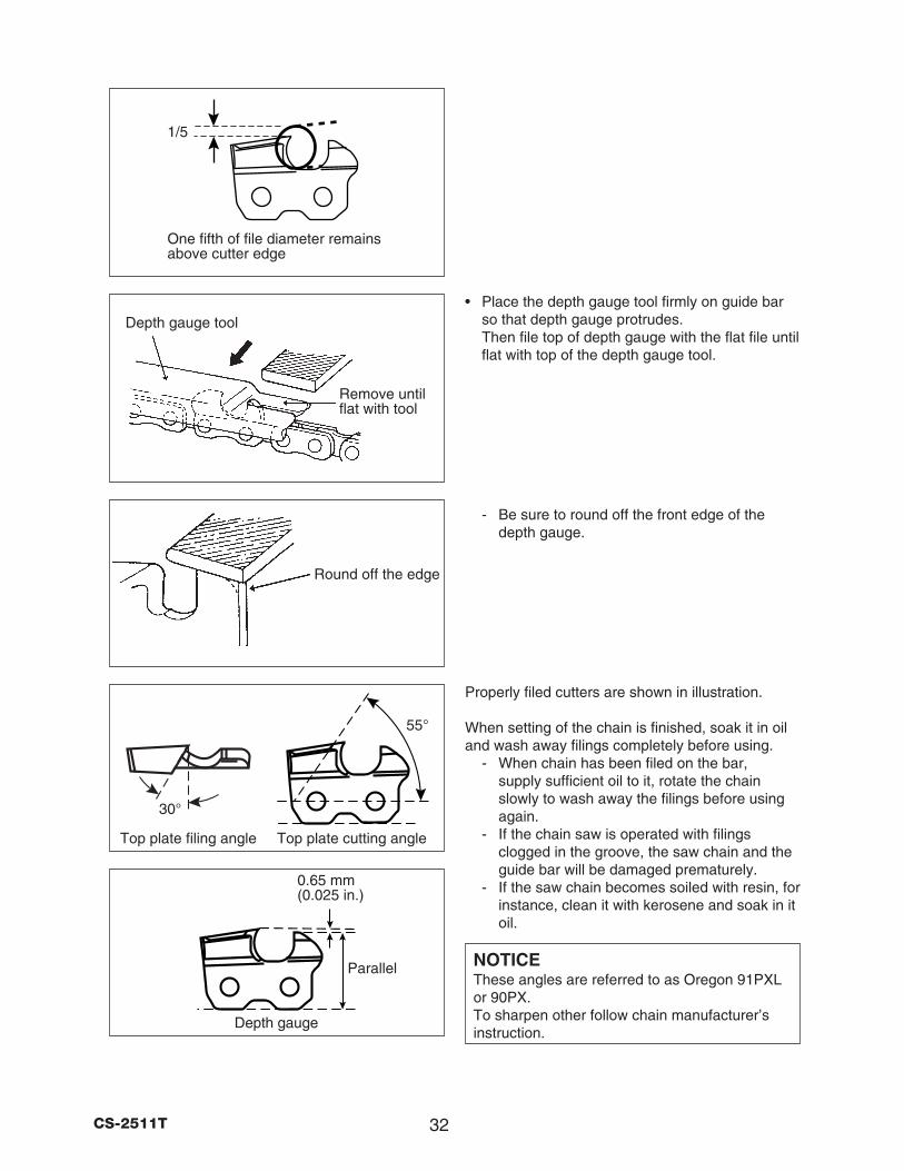
• Place the depth gauge tool firmly on guide bar so that depth gauge protrudes. Then file top of depth gauge with the flat file until flat with top of the depth gauge tool.
- Be sure to round off the front edge of the depth gauge.
Properly filed cutters are shown in illustration.
When setting of the chain is finished, soak it in oil and wash away filings completely before using.
- When chain has been filed on the bar, supply sufficient oil to it, rotate the chain slowly to wash away the filings before using again.
- If the chain saw is operated with filings clogged in the groove, the saw chain and the guide bar will be damaged prematurely.
- If the saw chain becomes soiled with resin, for instance, clean it with kerosene and soak in it oil.
NOTICEThese angles are referred to as Oregon 91PXL or 90PX. To sharpen other follow chain manufacturer’s instruction.
Remove until flat with tool
Depth gauge tool
Round off the edge
1/5
One fifth of file diameter remains above cutter edge
Top plate filing angle
30°
Parallel
0.65 mm (0.025 in.)
Top plate cutting angle
Depth gauge
55°
33 CS-2511T
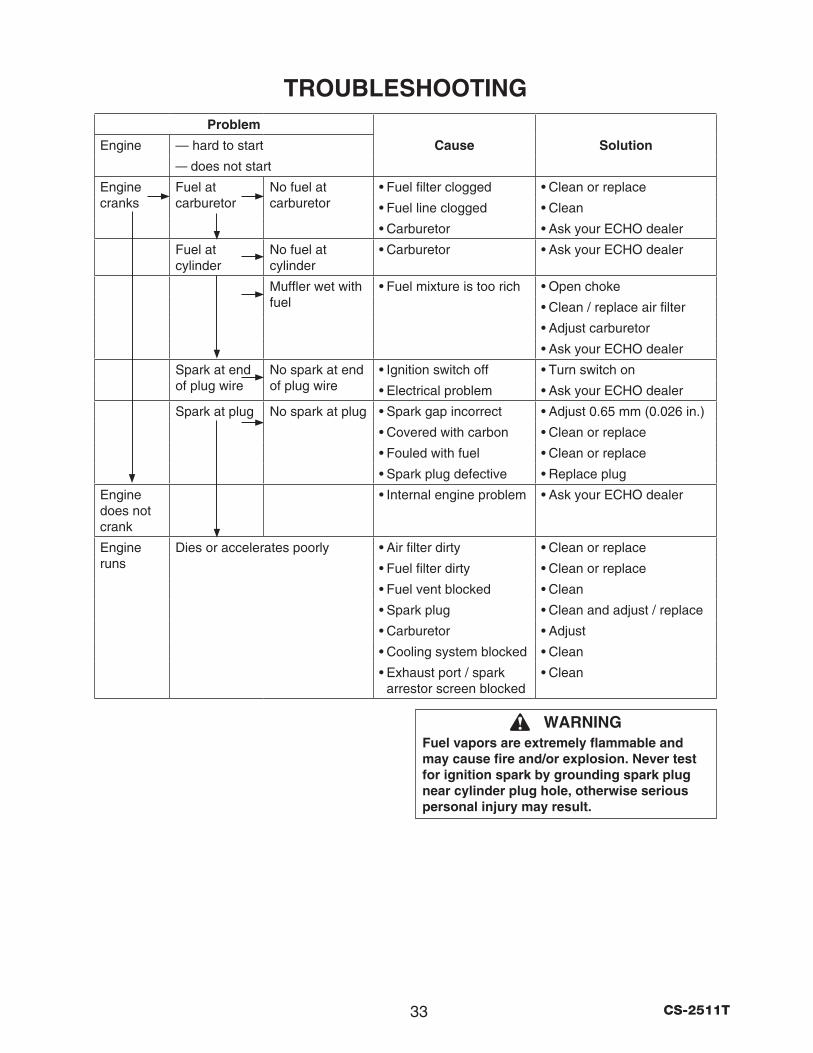
TROUBLESHOOTING
WARNINGFuel vapors are extremely flammable and may cause fire and/or explosion. Never test for ignition spark by grounding spark plug near cylinder plug hole, otherwise serious personal injury may result.
Problem
Engine — hard to start Cause Solution
— does not start
Engine cranks
Fuel at carburetor
No fuel at carburetor
• Fuel filter clogged • Clean or replace
• Fuel line clogged • Clean
• Carburetor • Ask your ECHO dealer
Fuel at cylinder
No fuel at cylinder
• Carburetor • Ask your ECHO dealer
Muffler wet with fuel
• Fuel mixture is too rich • Open choke
• Clean / replace air filter
• Adjust carburetor
• Ask your ECHO dealer
Spark at end of plug wire
No spark at end of plug wire
• Ignition switch off • Turn switch on
• Electrical problem • Ask your ECHO dealer
Spark at plug No spark at plug • Spark gap incorrect • Adjust 0.65 mm (0.026 in.)
• Covered with carbon • Clean or replace
• Fouled with fuel • Clean or replace
• Spark plug defective • Replace plug
Engine does not crank
• Internal engine problem • Ask your ECHO dealer
Engine runs
Dies or accelerates poorly • Air filter dirty • Clean or replace
• Fuel filter dirty • Clean or replace
• Fuel vent blocked • Clean
• Spark plug • Clean and adjust / replace
• Carburetor • Adjust
• Cooling system blocked • Clean
• Exhaust port / spark arrestor screen blocked
• Clean
34CS-2511T
* Technical data subject to change without notice.
TECHNICAL DATAMODEL CS-2511T
Dimension L × W × H mm (in) 243 × 205 × 196 (9.57 × 8.07 × 7.72 )Mass Power head, dry kg (lb) 2.3 (5.07) Without chain and guide barEngine Type Air-cooled two-stroke single cylinder
Displacement mL (in³) 25.0 (1.53)Carburetor Diaphragm typeMagneto Flywheel magneto: CDI systemSpark plug NGK CMR7HStarter Recoil starterPower transmission Automatic centrifugal clutch
Fuel Mixture ratio 50:1 ratio with ECHO Power Blend X™ or ECHO Red Armor® ISO-L-EGD (ISO/CD 13738) and JASO M345-FD two-stroke, air-cooled engine oil.
Gasoline Use 89 octane unleaded. Do not use fuel containing methyl alcohol, more than 10 % ethyl alcohol or 15 % MTBE. Do not use alternative fuels such as E-15 or E-85.
Tank capacity L (fl oz) 0.190 (6.42)Oil Bar and chain ECHO bar and chain oil
Tank capacity L (fl oz) 0.140 (4.73)Guide bar and saw chain
See page 23 for Chain and Guide Bar CombinationLubrication Adjustable automatic oil pump
Engine speed IdleRPM
2,800 - 3,600Clutch engagement 4,100 - 4,600Wide open throttle 12,200 - 13,400
Standard features
Front hand guard, Anti-vibration device, Throttle control lockout, Chain brake, Chain catcher, Spark arrestor muffler, (Kick guard), (Spiked bumper; option)
WARNINGDo not store in an enclosure where fuel fumes may accumlate or reach an open flame or spark.
CAUTIONDo not lend or rent your chain saw without the operators manual and Safety manual.
NOTICE• For future reference, you should keep this
operators manual and the Safety manual. • If this operators manual or the Safety manual
has become illegible or is lost, please purchase a new one from your ECHO dealer.
STORAGE AFTER USE• Inspect and adjust every part of the chain saw.
- Completely clean every part and repair if necessary.
- Apply thin coating of oil on metal parts to prevent rust.
• Remove chain and guide bar. • Drain fuel tank, pull starter slowly a few times to
drain fuel from carburetor. • Pour a small amount of clean motor oil into spark
plug hole, pull starter and crank the engine until piston reaches: TOP DEAD CENTER.
• Store in a dry area, free from dust.

35 CS-2511T
WARRANTY REGISTRATION SHEETThank you for choosing ECHO Power EquipmentPlease go to http://www.echo-usa.com/Warranty/Register-Your-ECHO to register your new product on-line. It’s FAST and EASY! NOTE: your information will never be sold or misused by ECHO, Inc. Registering your purchase enables us to contact you in the unlikely event of a service update or product recall, and verifies your ownership for warranty consideration.If you do not have access to the Internet, you can complete the form below and mail to:
ECHO Inc., Product Registration, PO Box 1139, Lake Zurich IL 60047.

C70215001001 - C70215999999