Embed Size (px)
Citation preview

INSTRUCTION MANUALCHAIN SAW
CS-271T
WARNINGRead the instructions carefully and follow the rules for safeoperation.Failure to do so could result in serious injury.
X750-018 73 2X750 323-580 2
ECHO, INCORPORATED400 Oakwood Road, Lake Zurich, Illinois 60047-1564Phone : 847-540-8400
Printed in Japan 1205F 0115 ES
Copyright © 2011 All Rights Reserved.
The engine exhaust from thisproduct contains chemicals knownto the State of California to cause
cancer, birth defects or otherreproductive harm.
WARNING

1 CS-271T
RULES FOR SAFE OPERATIONA. Kickback Safety Precautions for Chain Saw Users
1.With a basic understanding ofkickback, you can reduce or eliminatethe element of surprise.Sudden surprise contributes toaccidents.
2.Keep a good firm grip on the saw withboth hands, the right hand on the rearhandle, and the left hand on the fronthandle, when the engine is running.Use a firm grip with thumbs and fingersencircling the chain saw handles.A firm grip will help you reducekickback and maintain control of thesaw.Don’t let go.
3.Make sure that the area in which youare cutting is free from obstructions.Do not let the nose of the guide barcontact a log, branch, or any otherobstruction which could be hit whileyou are operating the saw.
4.Cut at high engine speeds.
5.Do not overreach or cut aboveshoulder height.
6.Follow manufacturer’s sharpening andmaintenance instructions for the sawchain.
7.Only use replacement bars and chainsspecified by the manufacturer or theequivalent.
WARNING!
KICKBACK may occur when the nose ortip of the guide bar touches an object, orwhen the wood closes in and pinches thesaw chain in the cut.
Tip contact in some cases may cause alightning fast reverse REACTION, Kickingthe guide bar up and back towards theoperator.Pinching the saw chain along the top ofthe guide bar may push the guide barrapidly back towards the operator.Either of these reactions may cause you tolose control of the saw which could resultin serious personal injury.
The Kick Guard® device is not installed onthe guide bar when you purchase yourECHO chain saw.The Kick Guard® can be used in a majorityof cutting operations, and is especiallyrecommended for beginners,homeowners, or chain saw novices.Most cutting operations can beaccomplished with the Kick Guard® inplace.
Do not rely exclusively upon the safetydevices built into your saw.As a chain saw user, you should takeseveral steps to keep your cutting jobsfree from accident or injury.
2CS-271T
1.Do not operate a chain saw with onehand! Serious injury to the operator,helpers, bystanders, or anycombination of these persons mayresult from one-handed operation.A chain saw is intended for two-handed use.
2.Do not operate a chain saw when youare fatigued.
3.Use safety footwear, snug-fittingclothing and protective gloves.Wear eye, hearing, and headprotection devices.
4.Use caution when handling fuel.Move the chain saw at least 3 m(10 feet) from the fueling point beforestarting the engine.
5.Do not allow other persons to be nearthe chain saw when starting or cuttingwith the chain saw.Keep bystanders and animals out ofthe work area.
6.Do not start cutting until you have aclear work area, secure footing, and aplanned retreat path from the fallingtree.
7.Keep all parts of your body away fromthe saw chain when the engine isrunning.
8.Before you start the engine, make surethat the saw chain is not contactinganything.
9.Carry the chain saw with the enginestopped, the guide bar and saw chainto the rear, and the muffler away fromyour body. When carrying a chain sawwith the engine running, push the fronthand guard forward to engage thechain brake.
10.Do not operate a chain saw that isdamaged, improperly adjusted, or notcompletely and securely assembled.Be sure that the saw chain stopsmoving when the throttle control triggeris released.
11.Shut off the engine before setting thechain saw down.
12.Use extreme caution when cuttingsmall size brush and saplings becauseslender material may catch the sawchain and be whipped toward you orpull you off balance.
13.When cutting a limb that is undertension, be alert for spring-back so thatyou will not be struck when the tensionin the wood fibers is released.
14.Keep the handles dry, clean, and freeof oil or fuel mixture.
15.Operate the chain saw only in wellventilated areas.
16.Do not operate a chain saw in a treeunless you have been specificallytrained to do so.
17.All chain saw service, other than itemslisted in the Instruction manualmaintenance instructions, should beperformed by competent servicepersonnel.(For example, if improper tools areused to remove the flywheel or if animproper tool is used to hold theflywheel in order to remove the clutch,structural damage to the flywheel couldoccur and could subsequently causethe flywheel to burst.)
18.When transporting your chain saw, usethe appropriate guide bar scabbard.
19.Spark arrestor mufflers approved toSAE Standard J335 are standard onECHO chain saws to reduce thepossibility of forest fires.Do not operate the chain saw with aloose or defective muffler.Do not remove the spark arrestorscreen.
B. Other Safety Precautions
3 CS-271T
WARNINGThe safety alert symbol accompanied by theword “WARNING” calls attention to an act orcondition which CAN lead to seriouspersonal injury or death if not avoided.
CAUTIONThe safety alert symbol accompanied by theword “CAUTION” calls attention to an act orcondition which may lead to minor ormoderate personal injury if not avoided.
NOTICEThis enclosed message provides tips for use,care and maintenance of the unit.
IMPORTANTThe enclosed message provides informationnecessary for the protection of the unit.
DANGERThe safety alert symbol accompanied by theword “DANGER” calls attention to an act orcondition which WILL lead to seriouspersonal injury or death if not avoided.
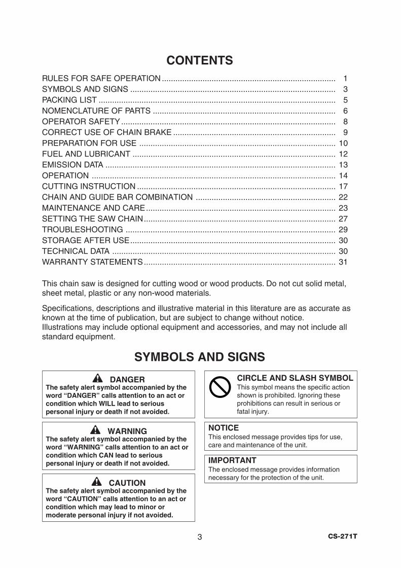
SYMBOLS AND SIGNS
CONTENTSRULES FOR SAFE OPERATION ............................................................................. 1SYMBOLS AND SIGNS ........................................................................................... 3PACKING LIST ......................................................................................................... 5NOMENCLATURE OF PARTS ................................................................................. 6OPERATOR SAFETY............................................................................................... 8CORRECT USE OF CHAIN BRAKE ........................................................................ 9PREPARATION FOR USE ....................................................................................... 10FUEL AND LUBRICANT .......................................................................................... 12EMISSION DATA ...................................................................................................... 13OPERATION ............................................................................................................ 14CUTTING INSTRUCTION ........................................................................................ 17CHAIN AND GUIDE BAR COMBINATION .............................................................. 22MAINTENANCE AND CARE.................................................................................... 23SETTING THE SAW CHAIN..................................................................................... 27TROUBLESHOOTING ............................................................................................. 29STORAGE AFTER USE........................................................................................... 30TECHNICAL DATA ................................................................................................... 30WARRANTY STATEMENTS..................................................................................... 31
This chain saw is designed for cutting wood or wood products. Do not cut solid metal,sheet metal, plastic or any non-wood materials.
Specifications, descriptions and illustrative material in this literature are as accurate asknown at the time of publication, but are subject to change without notice.Illustrations may include optional equipment and accessories, and may not include allstandard equipment.
CIRCLE AND SLASH SYMBOLThis symbol means the specific actionshown is prohibited. Ignoring theseprohibitions can result in serious orfatal injury.
4CS-271T
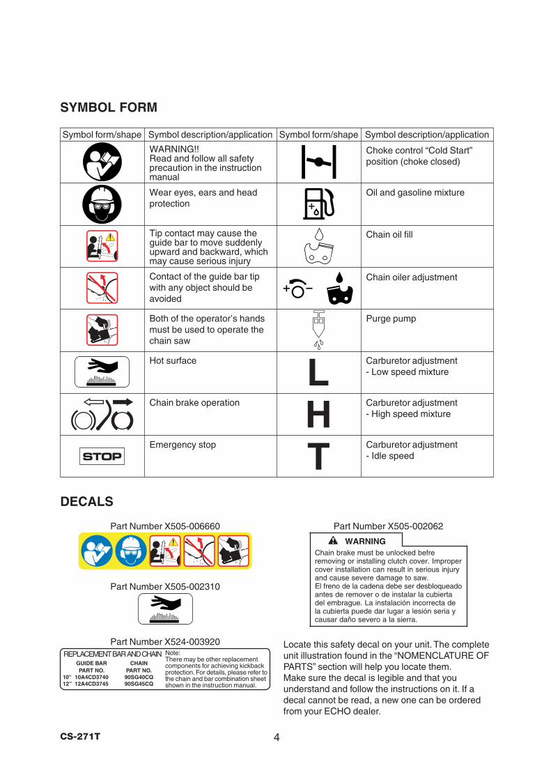
SYMBOL FORM
Carburetor adjustment- Idle speed
Carburetor adjustment- High speed mixture
WARNING!!Read and follow all safetyprecaution in the instructionmanual
Wear eyes, ears and headprotection
Carburetor adjustment- Low speed mixture
Oil and gasoline mixture
Symbol form/shape Symbol description/application Symbol form/shape Symbol description/application
Chain brake operation
DECALS
Locate this safety decal on your unit. The completeunit illustration found in the “NOMENCLATURE OFPARTS” section will help you locate them.Make sure the decal is legible and that youunderstand and follow the instructions on it. If adecal cannot be read, a new one can be orderedfrom your ECHO dealer.
Emergency stop
Choke control “Cold Start”position (choke closed)
STOP
Contact of the guide bar tipwith any object should beavoided
Tip contact may cause theguide bar to move suddenlyupward and backward, whichmay cause serious injury
Both of the operator’s handsmust be used to operate thechain saw
Chain oiler adjustment
Purge pump
Hot surface
Part Number X505-002310
WARNINGChain brake must be unlocked befreremoving or installing clutch cover. Impropercover installation can result in serious injuryand cause severe damage to saw.El freno de la cadena debe ser desbloqueadoantes de remover o de instalar la cubiertadel embrague. La instalación incorrecta dela cubierta puede dar lugar a lesión seria ycausar daño severo a la sierra.
Part Number X505-002062Part Number X505-006660
Chain oil fill
Part Number X524-003920REPLACEMENT BAR AND CHAIN
GUIDE BAR CHAINPART NO. PART NO.
10” 10A4CD3740 90SG40CQ12” 12A4CD3745 90SG45CQ
Note:There may be other replacementcomponents for achieving kickbackprotection. For details, please refer tothe chain and bar combination sheetshown in the instruction manual.
5 CS-271T
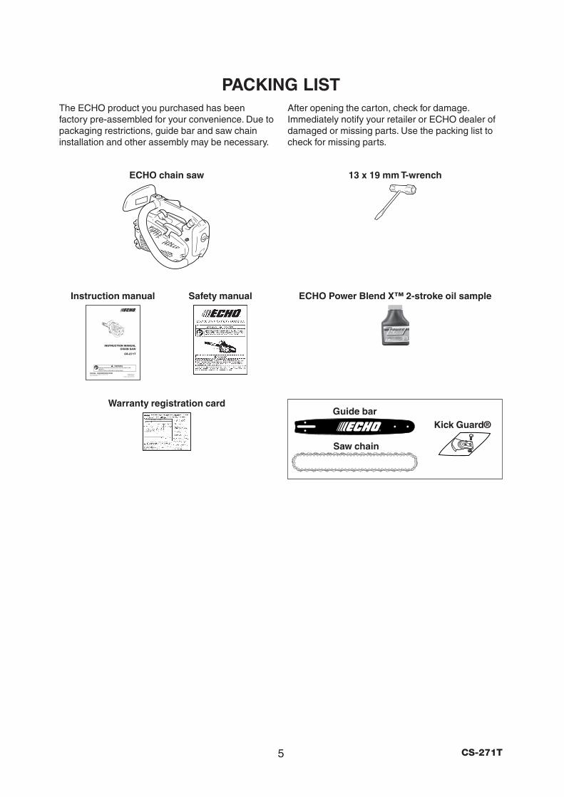
PACKING LISTThe ECHO product you purchased has beenfactory pre-assembled for your convenience. Due topackaging restrictions, guide bar and saw chaininstallation and other assembly may be necessary.
After opening the carton, check for damage.Immediately notify your retailer or ECHO dealer ofdamaged or missing parts. Use the packing list tocheck for missing parts.
Warranty registration card
13 x 19 mm T-wrench
ECHO Power Blend X™ 2-stroke oil sampleInstruction manual Safety manual
ECHO chain saw
Saw chain
Guide barKick Guard®
6CS-271T
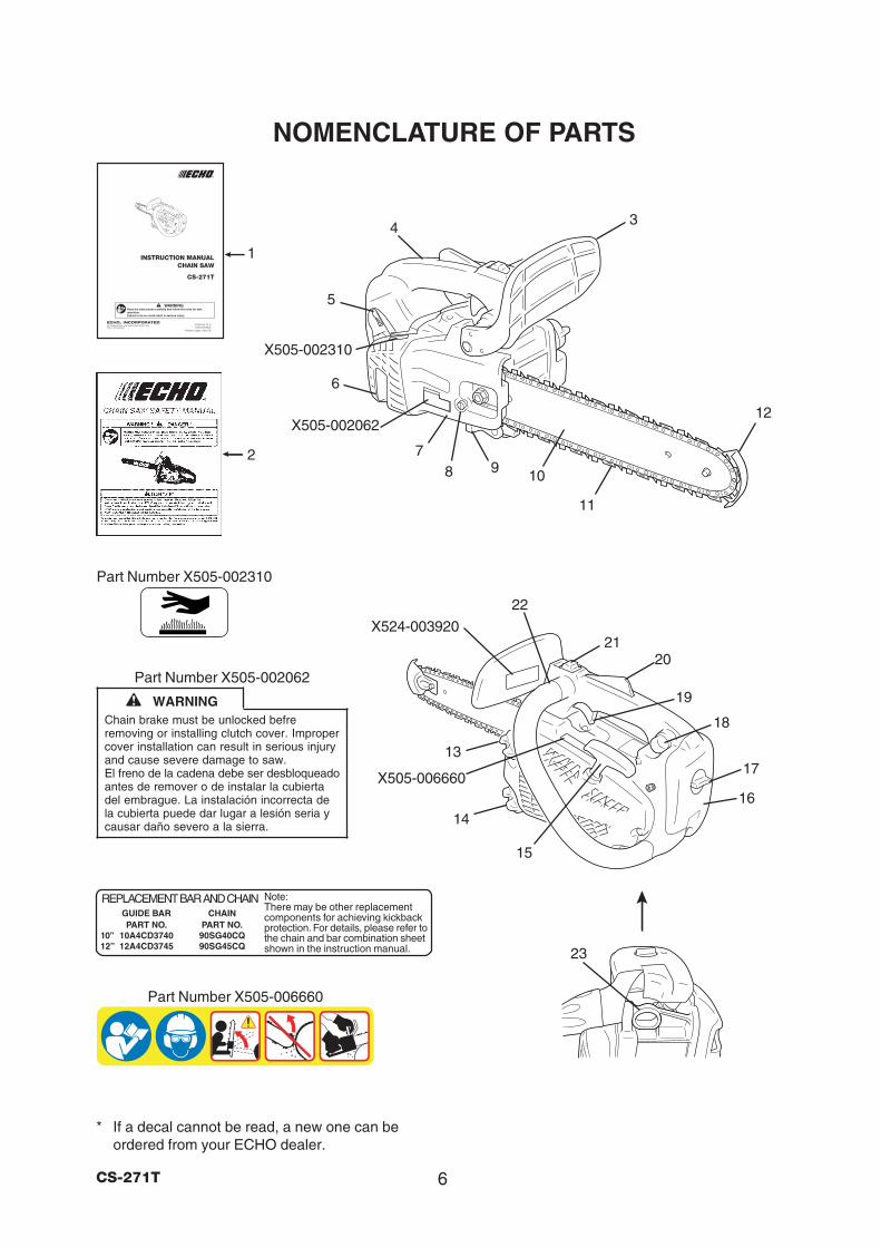
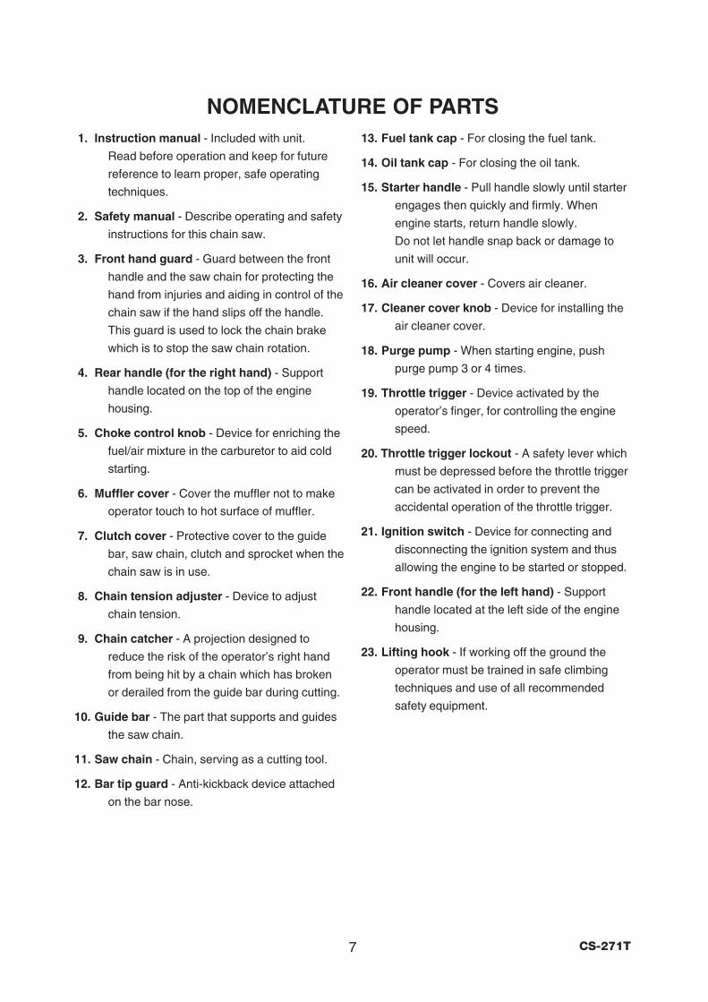
NOMENCLATURE OF PARTS
* If a decal cannot be read, a new one can beordered from your ECHO dealer.
19
14
15
17
16
5
4
87
10
11
12
3
2
1
X524-003920
X505-006660
9
21
6
22
20
Part Number X505-002310
WARNINGChain brake must be unlocked befreremoving or installing clutch cover. Impropercover installation can result in serious injuryand cause severe damage to saw.El freno de la cadena debe ser desbloqueadoantes de remover o de instalar la cubiertadel embrague. La instalación incorrecta dela cubierta puede dar lugar a lesión seria ycausar daño severo a la sierra.
Part Number X505-002062
X505-002310
X505-002062
Part Number X505-006660
23
18
REPLACEMENT BAR AND CHAINGUIDE BAR CHAINPART NO. PART NO.
10” 10A4CD3740 90SG40CQ12” 12A4CD3745 90SG45CQ
Note:There may be other replacementcomponents for achieving kickbackprotection. For details, please refer tothe chain and bar combination sheetshown in the instruction manual.
13
7 CS-271T
NOMENCLATURE OF PARTS1. Instruction manual - Included with unit.
Read before operation and keep for future
reference to learn proper, safe operating
techniques.
2. Safety manual - Describe operating and safety
instructions for this chain saw.
3. Front hand guard - Guard between the front
handle and the saw chain for protecting the
hand from injuries and aiding in control of the
chain saw if the hand slips off the handle.
This guard is used to lock the chain brake
which is to stop the saw chain rotation.
4. Rear handle (for the right hand) - Support
handle located on the top of the engine
housing.
5. Choke control knob - Device for enriching the
fuel/air mixture in the carburetor to aid cold
starting.
6. Muffler cover - Cover the muffler not to make
operator touch to hot surface of muffler.
7. Clutch cover - Protective cover to the guide
bar, saw chain, clutch and sprocket when the
chain saw is in use.
8. Chain tension adjuster - Device to adjust
chain tension.
9. Chain catcher - A projection designed to
reduce the risk of the operator’s right hand
from being hit by a chain which has broken
or derailed from the guide bar during cutting.
10. Guide bar - The part that supports and guides
the saw chain.
11. Saw chain - Chain, serving as a cutting tool.
12. Bar tip guard - Anti-kickback device attached
on the bar nose.
13. Fuel tank cap - For closing the fuel tank.
14. Oil tank cap - For closing the oil tank.
15. Starter handle - Pull handle slowly until starter
engages then quickly and firmly. When
engine starts, return handle slowly.
Do not let handle snap back or damage to
unit will occur.
16. Air cleaner cover - Covers air cleaner.
17. Cleaner cover knob - Device for installing the
air cleaner cover.
18. Purge pump - When starting engine, push
purge pump 3 or 4 times.
19. Throttle trigger - Device activated by the
operator’s finger, for controlling the engine
speed.
20. Throttle trigger lockout - A safety lever which
must be depressed before the throttle trigger
can be activated in order to prevent the
accidental operation of the throttle trigger.
21. Ignition switch - Device for connecting and
disconnecting the ignition system and thus
allowing the engine to be started or stopped.
22. Front handle (for the left hand) - Support
handle located at the left side of the engine
housing.
23. Lifting hook - If working off the ground the
operator must be trained in safe climbing
techniques and use of all recommended
safety equipment.
8CS-271T
OPERATOR SAFETYVIBRATION AND COLD• It is believed that a condition called Raynaud’s
Phenomenon, which affects the fingers of certainindividuals, may be brought about by exposure tovibration and cold.Exposure to vibration and cold may causetingling and burning followed by loss of color andnumbness in the fingers.The following precautions are stronglyrecommended because the minimum exposurewhich might trigger the ailment is unknown.
• Keep your body warm, especially the head andneck, feet and ankles and hands and wrists.
• Maintain good blood circulation by performingvigorous arm exercises during frequent workbreaks and also by not smoking.
• Limit the number of hours of operation.Try to fill each day with jobs where operating thechain saw, or other hand-held power equipmentis not required.
• If you experience discomfort redness andswelling of the fingers, followed by whitening andloss of feeling, consult your physician beforefurther exposing yourself to cold and vibration.
REPETITIVE STRESS INJURY• It is believed that over-using the muscles and
tendons of the finger, hands, arms and shouldersmay cause soreness, swelling, numbness,weakness and extreme pain to the areas justmentioned.Certain repetitive hand activities may put you ata high risk for developing a repetitive stressinjury (RSI).
• An extreme RSI condition is Carpal TunnelSyndrome (CTS) which could occur when yourwrist swells and squeezes a vital nerve that runsthrough the area. Some believe that prolongedexposure to vibration may contribute to CTS.CTS can cause severe pain for months or evenyears.
To reduce the risk of RSI/CTS, do the following:• Avoid using your wrist in a bent, extended or
twisted position.• Take periodic breaks to minimize repetition and
rest your hands.• Reduce the speed and force in which you do the
repetitive movement.• Do exercises to strengthen hand and arm
muscles.• See a doctor if you feel tingling, numbness or
pain in your fingers, hands, wrists or arms.The sooner RSI/CTS is diagnosed, the morelikely permanent nerve and muscle damage canbe prevented.
EYE AND HEARING PROTECTION• Wear eye protection goggles that meet ANSI
Z 87.1 requirements.Goggles meeting the requirements have themark “Z 87” stamped on them.
• Wear hearing protection.If this guideline is not followed, hearing loss canoccur.ECHO recommends wearing hearing protectionat all times.
WEAR PROPER CLOTHING• Snug fitting durable clothing should be worn.
Pants should have long legs, do not wear shorts.Do not wear loose fitting clothing, scarves,neckties, jewelry or any item that may becometangled in surrounding growth or the chain sawitself.
• Wear shoes with non-skid soles.Do not wear open toed shoes or operate unitbarefooted.
• Wear no-slip, heavy duty work gloves to improveyour grip on the chain saw handles.The gloves also help reduce the transmission ofmachine vibration to your hands.
HOT HUMID WEATHER• Heavy protective clothing can increase
operator fatigue which may lead to heatstroke.Schedule heavy work for early morning, or lateafternoon hours when temperatures are cooler.
AVOID HOT SURFACES• During operation, the muffler or catalytic muffler
and surrounding cover become hot.• Never suspend the saw on a lanyard with the
engine running.• Always use the saw from the right-hand side of
your body - never from the left side.• Always wear proper safety clothing to protect
your lower body from sharp saw chain and hotmuffler.
• Always keep exhaust area clear of flammabledebris during transportation or when storing,otherwise serious property damage or personalinjury may result.
9 CS-271T
SPARK ARRESTOR MUFFLER• The spark arrestor muffler controls the exhaust
noise and prevents hot, glowing particles ofcarbon from leaving the muffler.Make sure the spark arrestor screen is in goodrepair and properly seated in the muffler.
• Certain internal combustion engines operated onforest, brush, and/or grass-covered areas in thestates of Washington, Oregon, Idaho, California,Minnesota, New Jersey and Maine, are requiredto be equipped with a spark arrestor.
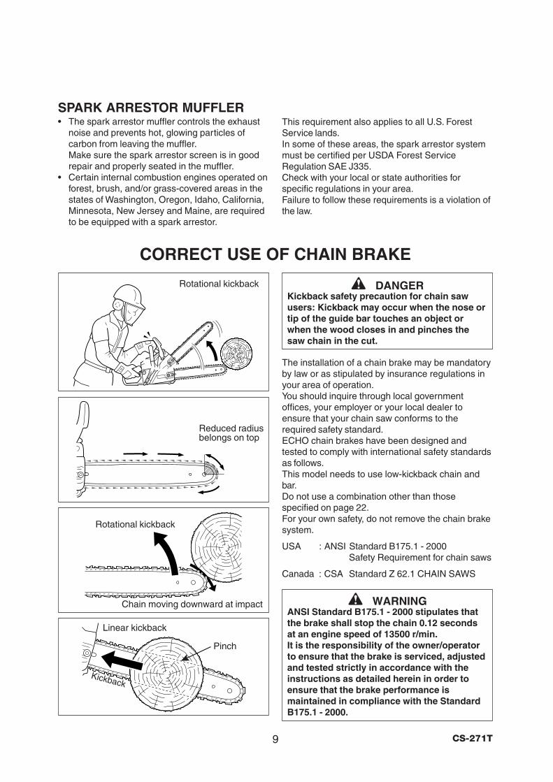
CORRECT USE OF CHAIN BRAKE
Linear kickback
Rotational kickback
Chain moving downward at impact
Rotational kickback
Reduced radiusbelongs on top
Pinch
Kickback
This requirement also applies to all U.S. ForestService lands.In some of these areas, the spark arrestor systemmust be certified per USDA Forest ServiceRegulation SAE J335.Check with your local or state authorities forspecific regulations in your area.Failure to follow these requirements is a violation ofthe law.
DANGERKickback safety precaution for chain sawusers: Kickback may occur when the nose ortip of the guide bar touches an object orwhen the wood closes in and pinches thesaw chain in the cut.
The installation of a chain brake may be mandatoryby law or as stipulated by insurance regulations inyour area of operation.You should inquire through local governmentoffices, your employer or your local dealer toensure that your chain saw conforms to therequired safety standard.ECHO chain brakes have been designed andtested to comply with international safety standardsas follows.This model needs to use low-kickback chain andbar.Do not use a combination other than thosespecified on page 22.For your own safety, do not remove the chain brakesystem.
USA : ANSI Standard B175.1 - 2000Safety Requirement for chain saws
Canada : CSA Standard Z 62.1 CHAIN SAWS
WARNINGANSI Standard B175.1 - 2000 stipulates thatthe brake shall stop the chain 0.12 secondsat an engine speed of 13500 r/min.It is the responsibility of the owner/operatorto ensure that the brake is serviced, adjustedand tested strictly in accordance with theinstructions as detailed herein in order toensure that the brake performance ismaintained in compliance with the StandardB175.1 - 2000.
10CS-271T
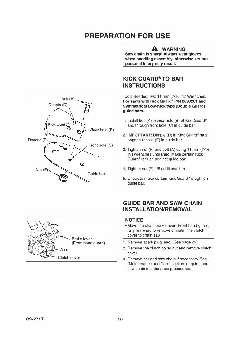
PREPARATION FOR USE
WARNINGSaw chain is sharp! Always wear gloveswhen handling assembly, otherwise seriouspersonal injury may result.
KICK GUARD® TO BARINSTRUCTIONS
Tools Needed: Two 11 mm (7/16 in.) Wrenches.For saws with Kick Guard® P/N 2893201 andSymmetrical Low-Kick type (Double Guard)guide bars.
1. Install bolt (A) in rear hole (B) of Kick Guard®
and through front hole (C) in guide bar.
2. IMPORTANT: Dimple (D) in Kick Guard® mustengage recess (E) in guide bar.
3. Tighten nut (F) and bolt (A) using 11 mm (7/16in.) wrenches until snug. Make certain KickGuard® is flush against guide bar.
4. Tighten nut (F) 1/8 additional turn.
5. Check to make certain Kick Guard® is tight onguide bar.
GUIDE BAR AND SAW CHAININSTALLATION/REMOVAL
NOTICE• Move the chain brake lever (Front hand guard)
fully rearward to remove or install the clutchcover to chain saw.
1. Remove spark plug lead. (See page 25)
2. Remove the clutch cover nut and remove clutchcover.
3. Remove bar and saw chain if necessary. See“Maintenance and Care” section for guide bar/saw chain maintenance procedures.
Bolt (A)Dimple (D)
Recess (E)Front hole (C)
Rear hole (B)
Nut (F)Guide bar
Kick Guard®
Clutch cover
Brake lever(Front hand guard)
A nut
11 CS-271T
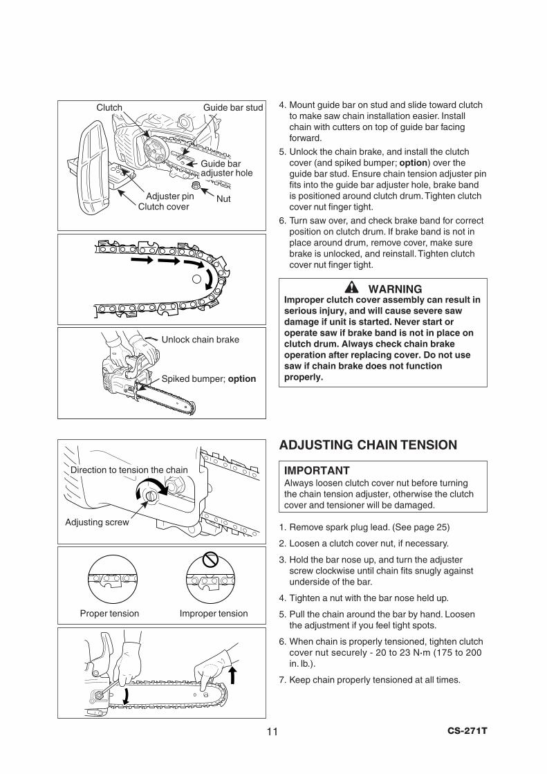
4. Mount guide bar on stud and slide toward clutchto make saw chain installation easier. Installchain with cutters on top of guide bar facingforward.
5. Unlock the chain brake, and install the clutchcover (and spiked bumper; option) over theguide bar stud. Ensure chain tension adjuster pinfits into the guide bar adjuster hole, brake bandis positioned around clutch drum. Tighten clutchcover nut finger tight.
6. Turn saw over, and check brake band for correctposition on clutch drum. If brake band is not inplace around drum, remove cover, make surebrake is unlocked, and reinstall. Tighten clutchcover nut finger tight.
WARNINGImproper clutch cover assembly can result inserious injury, and will cause severe sawdamage if unit is started. Never start oroperate saw if brake band is not in place onclutch drum. Always check chain brakeoperation after replacing cover. Do not usesaw if chain brake does not functionproperly.
ADJUSTING CHAIN TENSION
IMPORTANTAlways loosen clutch cover nut before turningthe chain tension adjuster, otherwise the clutchcover and tensioner will be damaged.
1. Remove spark plug lead. (See page 25)
2. Loosen a clutch cover nut, if necessary.
3. Hold the bar nose up, and turn the adjusterscrew clockwise until chain fits snugly againstunderside of the bar.
4. Tighten a nut with the bar nose held up.
5. Pull the chain around the bar by hand. Loosenthe adjustment if you feel tight spots.
6. When chain is properly tensioned, tighten clutchcover nut securely - 20 to 23 N·m (175 to 200in. lb.).
7. Keep chain properly tensioned at all times.
Adjusting screw
Proper tension Improper tension
Unlock chain brake
Direction to tension the chain
Guide baradjuster hole
Clutch coverNutAdjuster pin
Clutch Guide bar stud
Spiked bumper; option
12CS-271T
FUEL AND LUBRICANT
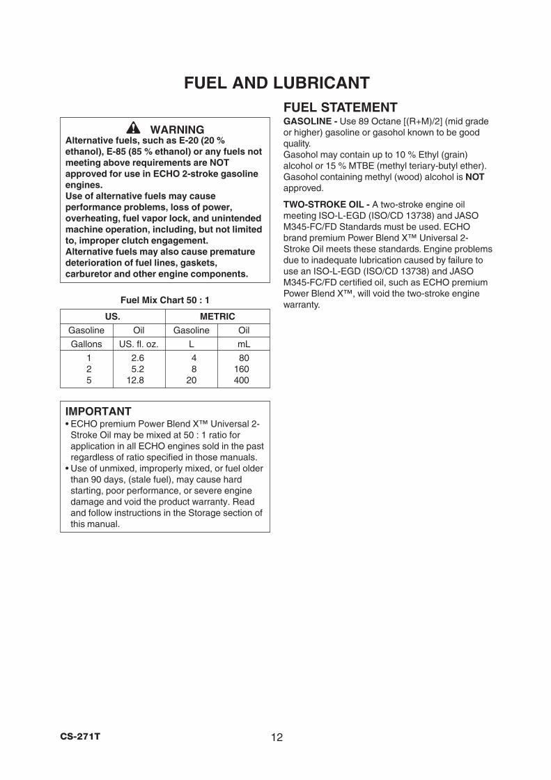
Fuel Mix Chart 50 : 1
US. METRIC
Gasoline Oil Gasoline Oil
Gallons US. fl. oz. L mL
1 2.6 4 802 5.2 8 1605 12.8 20 400
FUEL STATEMENTGASOLINE - Use 89 Octane [(R+M)/2] (mid gradeor higher) gasoline or gasohol known to be goodquality.Gasohol may contain up to 10 % Ethyl (grain)alcohol or 15 % MTBE (methyl teriary-butyl ether).Gasohol containing methyl (wood) alcohol is NOTapproved.
TWO-STROKE OIL - A two-stroke engine oilmeeting ISO-L-EGD (ISO/CD 13738) and JASOM345-FC/FD Standards must be used. ECHObrand premium Power Blend X™ Universal 2-Stroke Oil meets these standards. Engine problemsdue to inadequate lubrication caused by failure touse an ISO-L-EGD (ISO/CD 13738) and JASOM345-FC/FD certified oil, such as ECHO premiumPower Blend X™, will void the two-stroke enginewarranty.
IMPORTANT• ECHO premium Power Blend X™ Universal 2-
Stroke Oil may be mixed at 50 : 1 ratio forapplication in all ECHO engines sold in the pastregardless of ratio specified in those manuals.
• Use of unmixed, improperly mixed, or fuel olderthan 90 days, (stale fuel), may cause hardstarting, poor performance, or severe enginedamage and void the product warranty. Readand follow instructions in the Storage section ofthis manual.
WARNINGAlternative fuels, such as E-20 (20 %ethanol), E-85 (85 % ethanol) or any fuels notmeeting above requirements are NOTapproved for use in ECHO 2-stroke gasolineengines.Use of alternative fuels may causeperformance problems, loss of power,overheating, fuel vapor lock, and unintendedmachine operation, including, but not limitedto, improper clutch engagement.Alternative fuels may also cause prematuredeterioration of fuel lines, gaskets,carburetor and other engine components.
13 CS-271T
HANDLING FUELMIXING INSTRUCTIONS -1. Fill an approved fuel container with half of the
required amount of gasoline.
2. Add the proper amount of two-stroke oil togasoline.
3. Close container and shake to mix oil withgasoline.
4. Add remaining gasoline, close fuel container,and remix.
IMPORTANT• Spilled fuel is a leading cause of hydrocarbon
emissions. Some states may require the use ofautomatic fuel shut-off containers to reduce fuelspillage.
• Stored fuel ages.Do not mix more fuel than you expect to use inthirty (30) days, ninety (90) days when a fuelstabilizer is added.
• Stored two-stroke fuel may separate. ALWAYSshake fuel container thoroughly before eachuse.
AFTER USE -DO NOT store a unit with fuel in its tank. Leaks canoccur. Return unused fuel to an approved fuelstorage container.
STORAGE -Fuel storage laws vary by locality. Contact yourlocal government for the laws affecting your area.As a precaution, store fuel in an approved, airtightcontainer. Store in a well-ventilated, unoccupiedbuilding, away from sparks and flames.
DANGERFuel is VERY flammable. Use extreme carewhen mixing, storing or handling or seriouspersonal injury may result.• Use an approved fuel container.• DO NOT smoke near fuel.• DO NOT allow flames or sparks near fuel.• Fuel tanks/cans may be under pressure.
Always loosen fuel caps slowly allowingpressure to equalize.
• NEVER refuel a unit when the engine isHOT!
• NEVER refuel a unit with the enginerunning.
• DO NOT fill fuel tanks indoors.ALWAYS fill fuel tanks outdoors over bareground.
• Securely tighten fuel cap after refueling.• Inspect for fuel leakage.
If fuel leakage is found, do not start oroperate unit until leakage is repaired.
• Move at least 3 m (10 feet) from refuelinglocation before starting the engine.
EMISSION DATAEMISSION CONTROL(EXHAUST and EVAPORATIVE) EPA 2010 and/or C.A.R.B. TIER IIIThe emission control system for the engine is EM/TWC (Engine Modification and 3-way Catalyst) andfor the fuel tank the Control System is EVAP(Evaporative Emissions) or N (for nylon tank).Evaporative emission may be applicable toCalifornia models only.
An Emission Control Label is located on theengine. (This is an example only, information onlabel varies by engine family).
PRODUCT EMISSION DURABILITY(EMISSION COMPLIANCE PERIOD)The 300 hours emission compliance period isthe time span selected by the manufacturercertifying the engine emissions output meetsapplicable emissions regulations, provided thatapproved maintenance procedures are followedas listed in the Maintenance Section of thismanual.
EMISSION CONTROL INFORMATIONENGINE FAMILY: #EHXS.0274EA DISPLACEMENT: 26.9ccEMISSION COMPLIANCE PERIOD: 300HoursTHIS ENGINE MEETS * * * * U.S.EPA EXH/EVP & CALIFORNIAEXH/EVP EMISSION REGULATIONS FOR S.O.R.E. REFER TO OWNER’SMANUAL FOR MAINTENANCE SPECIFICATIONS AND ADJUSTMENTS.
* * * ? ? ? ?
14CS-271T
Oil tank cap
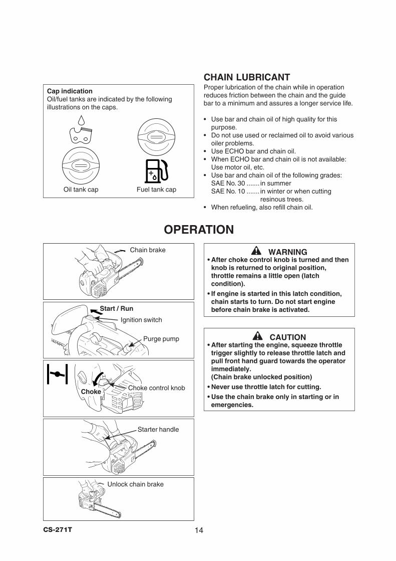
CHAIN LUBRICANTProper lubrication of the chain while in operationreduces friction between the chain and the guidebar to a minimum and assures a longer service life.
• Use bar and chain oil of high quality for thispurpose.
• Do not use used or reclaimed oil to avoid variousoiler problems.
• Use ECHO bar and chain oil.• When ECHO bar and chain oil is not available:
Use motor oil, etc.• Use bar and chain oil of the following grades:
SAE No. 30 ....... in summerSAE No. 10 ....... in winter or when cutting
resinous trees.• When refueling, also refill chain oil.
OPERATION
WARNING• After choke control knob is turned and then
knob is returned to original position,throttle remains a little open (latchcondition).
• If engine is started in this latch condition,chain starts to turn. Do not start enginebefore chain brake is activated.
CAUTION• After starting the engine, squeeze throttle
trigger slightly to release throttle latch andpull front hand guard towards the operatorimmediately.(Chain brake unlocked position)
• Never use throttle latch for cutting.
• Use the chain brake only in starting or inemergencies.
Start / Run
Ignition switch
Chain brake
Starter handle
Unlock chain brake
Purge pump
Fuel tank cap
Cap indicationOil/fuel tanks are indicated by the followingillustrations on the caps.
Choke Choke control knob
15 CS-271T
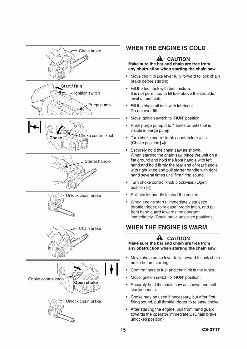
WHEN THE ENGINE IS COLD
CAUTIONMake sure the bar and chain are free fromany obstruction when starting the chain saw.
• Move chain brake lever fully forward to lock chainbrake before starting.
• Fill the fuel tank with fuel mixture.It is not permitted to fill fuel above the shoulderlevel of fuel tank.
• Fill the chain oil tank with lubricant.Do not over fill.
• Move ignition switch to “RUN” position.
• Push purge pump 3 to 4 times or until fuel isvisible in purge pump.
• Turn choke control knob counterclockwise.(Choke position )
• Securely hold the chain saw as shown.When starting the chain saw place the unit on aflat ground and hold the front handle with lefthand and hold firmly the rear end of rear handlewith right knee and pull starter handle with righthand several times until first firing sound.
• Turn choke control knob clockwise. (Openposition )
• Pull starter handle to start the engine.
• When engine starts, immediately squeezethrottle trigger, to release throttle latch, and pullfront hand guard towards the operatorimmediately. (Chain brake unlocked position)
WHEN THE ENGINE IS WARM
CAUTIONMake sure the bar and chain are free fromany obstruction when starting the chain saw.
• Move chain brake lever fully forward to lock chainbrake before starting.
• Confirm there is fuel and chain oil in the tanks.
• Move ignition switch to “RUN” position.
• Securely hold the chain saw as shown and pullstarter handle.
• Choke may be used if necessary, but after firstfiring sound, pull throttle trigger to release choke.
• After starting the engine, pull front hand guardtowards the operator immediately. (Chain brakeunlocked position)
Open chokeChoke control knob
Chain brake
Chain brake
Start / Run
Ignition switch
Starter handle
Purge pump
Choke Choke control knob
Unlock chain brake
Unlock chain brake
16CS-271T
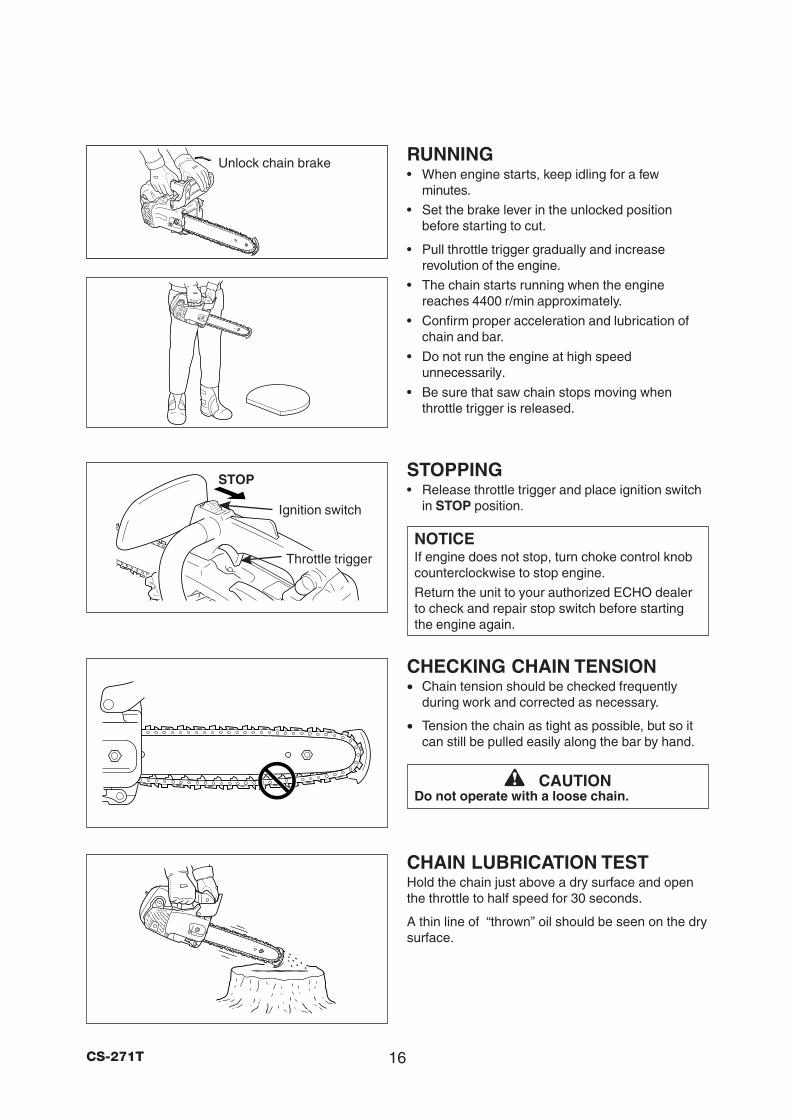
RUNNING• When engine starts, keep idling for a few
minutes.
• Set the brake lever in the unlocked positionbefore starting to cut.
• Pull throttle trigger gradually and increaserevolution of the engine.
• The chain starts running when the enginereaches 4400 r/min approximately.
• Confirm proper acceleration and lubrication ofchain and bar.
• Do not run the engine at high speedunnecessarily.
• Be sure that saw chain stops moving whenthrottle trigger is released.
STOPPING• Release throttle trigger and place ignition switch
in STOP position.
NOTICEIf engine does not stop, turn choke control knobcounterclockwise to stop engine.
Return the unit to your authorized ECHO dealerto check and repair stop switch before startingthe engine again.
CHECKING CHAIN TENSION• Chain tension should be checked frequently
during work and corrected as necessary.
• Tension the chain as tight as possible, but so itcan still be pulled easily along the bar by hand.
CAUTIONDo not operate with a loose chain.
CHAIN LUBRICATION TESTHold the chain just above a dry surface and openthe throttle to half speed for 30 seconds.
A thin line of “thrown” oil should be seen on the drysurface.
STOP
Ignition switch
Throttle trigger
Unlock chain brake
17 CS-271T
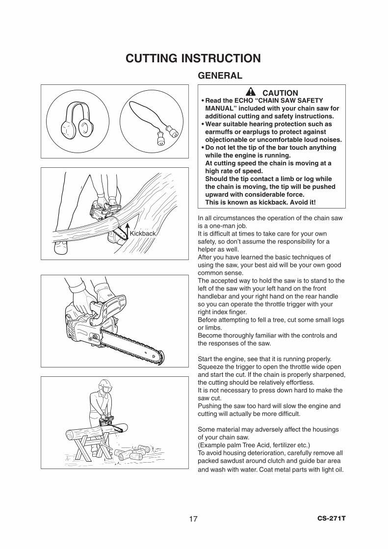
CUTTING INSTRUCTIONGENERAL
CAUTION• Read the ECHO “CHAIN SAW SAFETY
MANUAL” included with your chain saw foradditional cutting and safety instructions.
• Wear suitable hearing protection such asearmuffs or earplugs to protect againstobjectionable or uncomfortable loud noises.
• Do not let the tip of the bar touch anythingwhile the engine is running.At cutting speed the chain is moving at ahigh rate of speed.Should the tip contact a limb or log whilethe chain is moving, the tip will be pushedupward with considerable force.This is known as kickback. Avoid it!
In all circumstances the operation of the chain sawis a one-man job.It is difficult at times to take care for your ownsafety, so don’t assume the responsibility for ahelper as well.After you have learned the basic techniques ofusing the saw, your best aid will be your own goodcommon sense.The accepted way to hold the saw is to stand to theleft of the saw with your left hand on the fronthandlebar and your right hand on the rear handleso you can operate the throttle trigger with yourright index finger.Before attempting to fell a tree, cut some small logsor limbs.Become thoroughly familiar with the controls andthe responses of the saw.
Start the engine, see that it is running properly.Squeeze the trigger to open the throttle wide openand start the cut. If the chain is properly sharpened,the cutting should be relatively effortless.It is not necessary to press down hard to make thesaw cut.Pushing the saw too hard will slow the engine andcutting will actually be more difficult.
Some material may adversely affect the housingsof your chain saw.(Example palm Tree Acid, fertilizer etc.)To avoid housing deterioration, carefully remove allpacked sawdust around clutch and guide bar areaand wash with water. Coat metal parts with light oil.
Kickback
18CS-271T
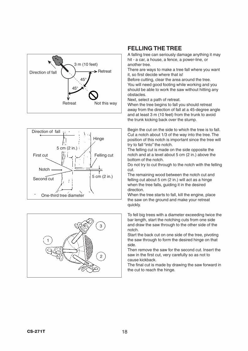
FELLING THE TREEA falling tree can seriously damage anything it mayhit - a car, a house, a fence, a power-line, oranother tree.There are ways to make a tree fall where you wantit, so first decide where that is!Before cutting, clear the area around the tree.You will need good footing while working and youshould be able to work the saw without hitting anyobstacles.Next, select a path of retreat.When the tree begins to fall you should retreataway from the direction of fall at a 45-degree angleand at least 3 m (10 feet) from the trunk to avoidthe trunk kicking back over the stump.
Begin the cut on the side to which the tree is to fall.Cut a notch about 1/3 of the way into the tree. Theposition of this notch is important since the tree willtry to fall “into” the notch.The felling cut is made on the side opposite thenotch and at a level about 5 cm (2 in.) above thebottom of the notch.Do not try to cut through to the notch with the fellingcut.The remaining wood between the notch cut andfelling cut about 5 cm (2 in.) will act as a hingewhen the tree falls, guiding it in the desireddirection.When the tree starts to fall, kill the engine, placethe saw on the ground and make your retreatquickly.
To fell big trees with a diameter exceeding twice thebar length, start the notching cuts from one sideand draw the saw through to the other side of thenotch.Start the back cut on one side of the tree, pivotingthe saw through to form the desired hinge on thatside.Then remove the saw for the second cut. Insert thesaw in the first cut, very carefully so as not tocause kickback.The final cut is made by drawing the saw forward inthe cut to reach the hinge.
1
2
3
Felling cut
Hinge
Direction of fall
First cut
Notch
Second cut
One-third tree diameter
Direction of fall
5 cm (2 in.)
5 cm (2 in.)
45°
45°
Not this way
Retreat
Retreat
3 m (10 feet)
19 CS-271T
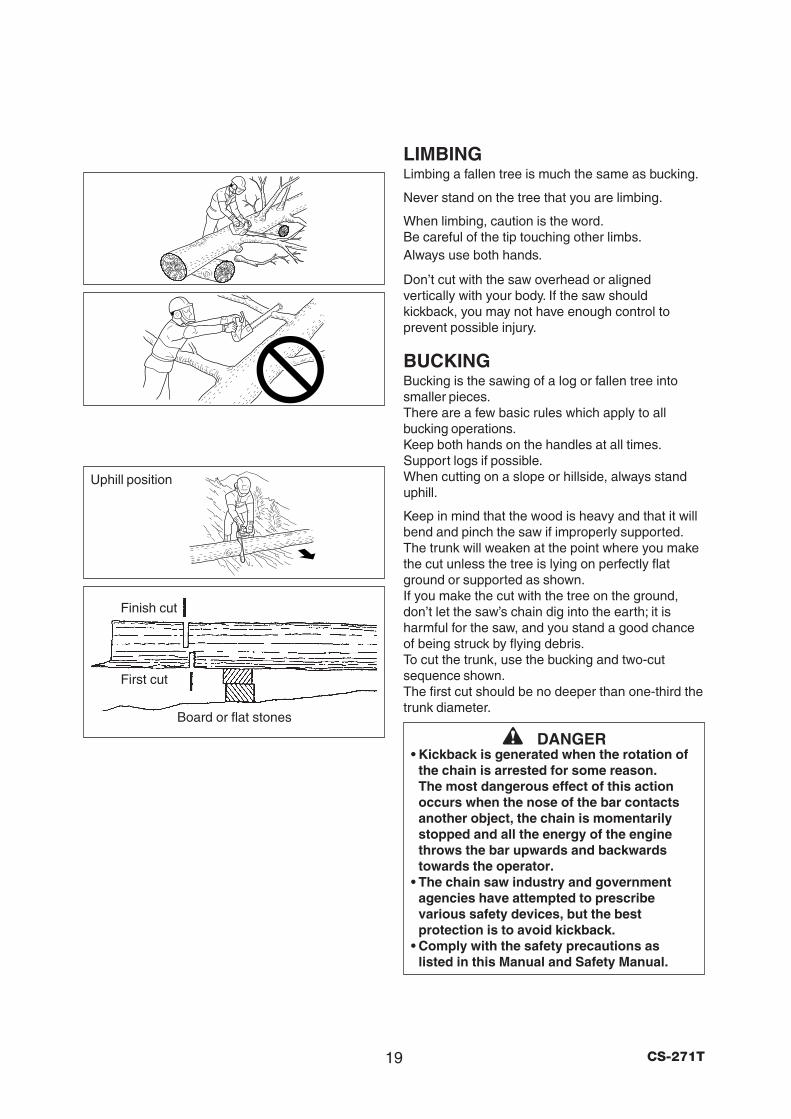
LIMBINGLimbing a fallen tree is much the same as bucking.
Never stand on the tree that you are limbing.
When limbing, caution is the word.Be careful of the tip touching other limbs.Always use both hands.
Don’t cut with the saw overhead or alignedvertically with your body. If the saw shouldkickback, you may not have enough control toprevent possible injury.
BUCKINGBucking is the sawing of a log or fallen tree intosmaller pieces.There are a few basic rules which apply to allbucking operations.Keep both hands on the handles at all times.Support logs if possible.When cutting on a slope or hillside, always standuphill.
Keep in mind that the wood is heavy and that it willbend and pinch the saw if improperly supported.The trunk will weaken at the point where you makethe cut unless the tree is lying on perfectly flatground or supported as shown.If you make the cut with the tree on the ground,don’t let the saw’s chain dig into the earth; it isharmful for the saw, and you stand a good chanceof being struck by flying debris.To cut the trunk, use the bucking and two-cutsequence shown.The first cut should be no deeper than one-third thetrunk diameter.
DANGER• Kickback is generated when the rotation of
the chain is arrested for some reason.The most dangerous effect of this actionoccurs when the nose of the bar contactsanother object, the chain is momentarilystopped and all the energy of the enginethrows the bar upwards and backwardstowards the operator.
• The chain saw industry and governmentagencies have attempted to prescribevarious safety devices, but the bestprotection is to avoid kickback.
• Comply with the safety precautions aslisted in this Manual and Safety Manual.
Uphill position
Finish cut
First cut
Board or flat stones
20CS-271T
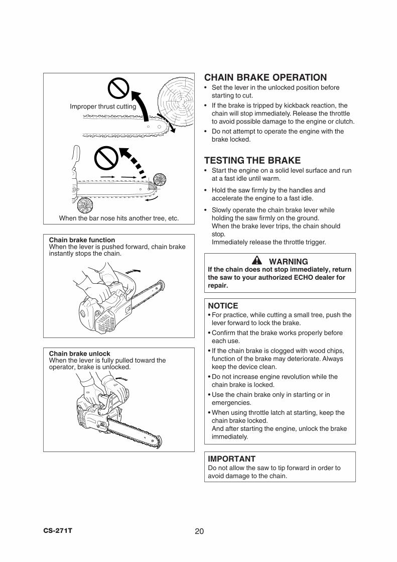
Chain brake functionWhen the lever is pushed forward, chain brakeinstantly stops the chain.
Chain brake unlockWhen the lever is fully pulled toward theoperator, brake is unlocked.
When the bar nose hits another tree, etc.
Improper thrust cutting
CHAIN BRAKE OPERATION• Set the lever in the unlocked position before
starting to cut.
• If the brake is tripped by kickback reaction, thechain will stop immediately. Release the throttleto avoid possible damage to the engine or clutch.
• Do not attempt to operate the engine with thebrake locked.
TESTING THE BRAKE• Start the engine on a solid level surface and run
at a fast idle until warm.
• Hold the saw firmly by the handles andaccelerate the engine to a fast idle.
• Slowly operate the chain brake lever whileholding the saw firmly on the ground.When the brake lever trips, the chain shouldstop.Immediately release the throttle trigger.
WARNINGIf the chain does not stop immediately, returnthe saw to your authorized ECHO dealer forrepair.
NOTICE• For practice, while cutting a small tree, push the
lever forward to lock the brake.
• Confirm that the brake works properly beforeeach use.
• If the chain brake is clogged with wood chips,function of the brake may deteriorate. Alwayskeep the device clean.
• Do not increase engine revolution while thechain brake is locked.
• Use the chain brake only in starting or inemergencies.
• When using throttle latch at starting, keep thechain brake locked.And after starting the engine, unlock the brakeimmediately.
IMPORTANTDo not allow the saw to tip forward in order toavoid damage to the chain.
21 CS-271T
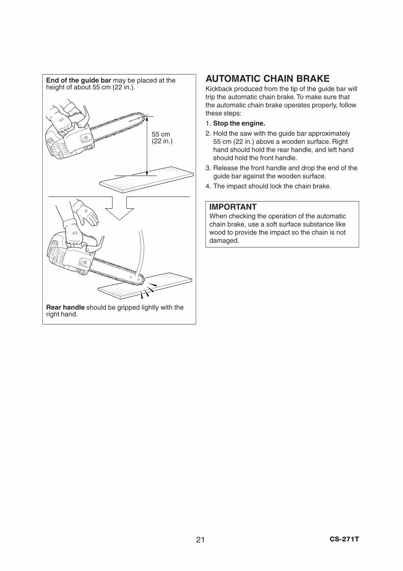
End of the guide bar may be placed at theheight of about 55 cm (22 in.).
55 cm(22 in.)
AUTOMATIC CHAIN BRAKEKickback produced from the tip of the guide bar willtrip the automatic chain brake. To make sure thatthe automatic chain brake operates properly, followthese steps:
1. Stop the engine.
2. Hold the saw with the guide bar approximately55 cm (22 in.) above a wooden surface. Righthand should hold the rear handle, and left handshould hold the front handle.
3. Release the front handle and drop the end of theguide bar against the wooden surface.
4. The impact should lock the chain brake.
IMPORTANTWhen checking the operation of the automaticchain brake, use a soft surface substance likewood to provide the impact so the chain is notdamaged.
Rear handle should be gripped lightly with theright hand.
22CS-271T
CHAIN AND GUIDE BAR COMBINATIONThe following combinations are recommended for model CS-271T.
GUIDE BAR(Low-kickback)Replacement guide bars.The following guide bars may be considered tohave equivalent kickback energy.• Sprocket nose guide bars of the same length
and nose radius, same pitch and having thesame number of teeth.
• Hard nose guide bars of the same length andnose radius as a sprocket nose bar.
SAW CHAIN(Low-kickback)
CAUTIONDo not use replacement saw chain unless ithas been designated as meeting the ANSIB175.1 - 2000 kickback performancerequirements, when tested on therepresentative sample of chain saws below3.8 c.i.d. specified in ANSI B175.1 - 2000.
NOTICELOW KICKBACK SAW CHAIN meets thekickback performance requirements of ANSIB175.1-2000 (safety requirements for gasoline-powered chain saws).
Guide bar Saw chain
Length mm (in) Part No. Pitch mm (in) Part No. Links
254 (10)10A4CD3740
9.53 (3/8)90SG40CQ
4010A0CD3740 91VG40CQ
305 (12)12A4CD3745
9.53 (3/8)90SG45CQ
4512A0CD3745 91VG45CQ
23 CS-271T
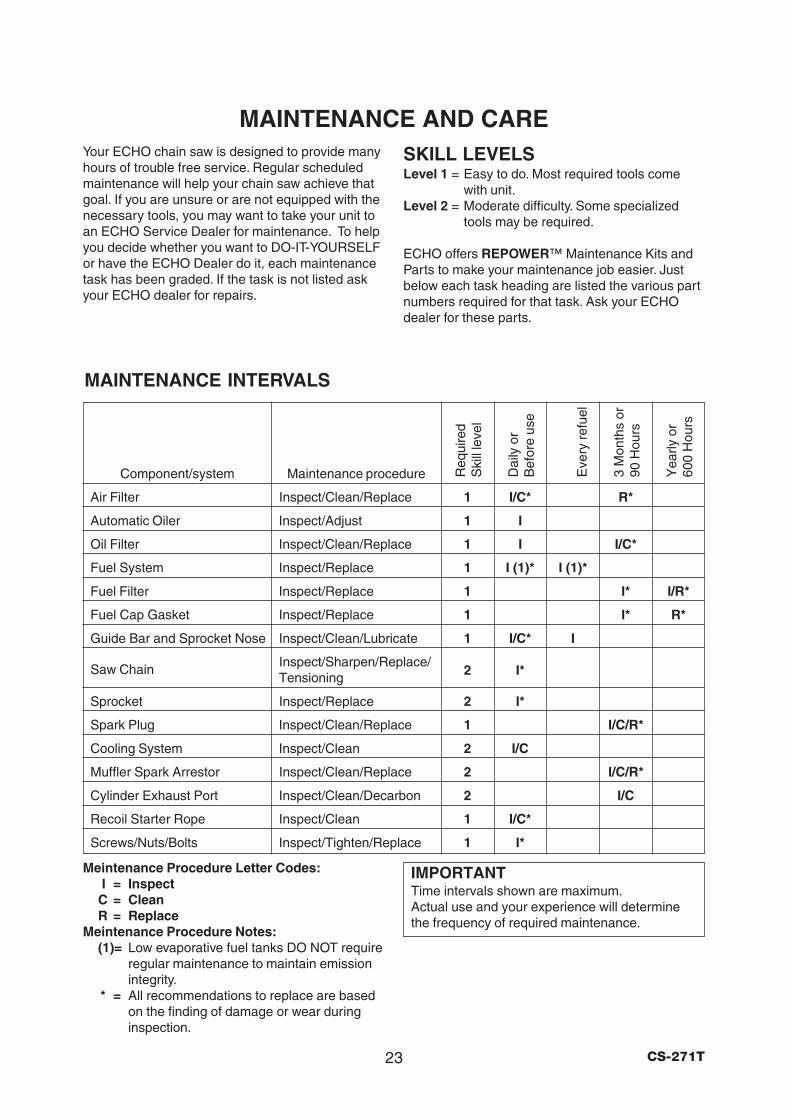
MAINTENANCE AND CARE
IMPORTANTTime intervals shown are maximum.Actual use and your experience will determinethe frequency of required maintenance.
Your ECHO chain saw is designed to provide manyhours of trouble free service. Regular scheduledmaintenance will help your chain saw achieve thatgoal. If you are unsure or are not equipped with thenecessary tools, you may want to take your unit toan ECHO Service Dealer for maintenance. To helpyou decide whether you want to DO-IT-YOURSELFor have the ECHO Dealer do it, each maintenancetask has been graded. If the task is not listed askyour ECHO dealer for repairs.
SKILL LEVELSLevel 1 = Easy to do. Most required tools come
with unit.Level 2 = Moderate difficulty. Some specialized
tools may be required.
ECHO offers REPOWER™ Maintenance Kits andParts to make your maintenance job easier. Justbelow each task heading are listed the various partnumbers required for that task. Ask your ECHOdealer for these parts.
MAINTENANCE INTERVALS
Meintenance Procedure Letter Codes:I = Inspect
C = CleanR = Replace
Meintenance Procedure Notes:(1)= Low evaporative fuel tanks DO NOT require
regular maintenance to maintain emissionintegrity.
* = All recommendations to replace are basedon the finding of damage or wear duringinspection.
Component/system Maintenance procedure
Air Filter Inspect/Clean/Replace 1 I/C* R*
Automatic Oiler Inspect/Adjust 1 I
Oil Filter Inspect/Clean/Replace 1 I I/C*
Fuel System Inspect/Replace 1 I (1)* I (1)*
Fuel Filter Inspect/Replace 1 I* I/R*
Fuel Cap Gasket Inspect/Replace 1 I* R*
Guide Bar and Sprocket Nose Inspect/Clean/Lubricate 1 I/C* I
Saw Chain Inspect/Sharpen/Replace/Tensioning 2 I*
Sprocket Inspect/Replace 2 I*
Spark Plug Inspect/Clean/Replace 1 I/C/R*
Cooling System Inspect/Clean 2 I/C
Muffler Spark Arrestor Inspect/Clean/Replace 2 I/C/R*
Cylinder Exhaust Port Inspect/Clean/Decarbon 2 I/C
Recoil Starter Rope Inspect/Clean 1 I/C*
Screws/Nuts/Bolts Inspect/Tighten/Replace 1 I*
Eve
ry r
efue
l
Req
uire
dS
kill
leve
l
Dai
ly o
rB
efor
e us
e
3 M
onth
s or
90 H
ours
Yea
rly o
r60
0 H
ours
24CS-271T
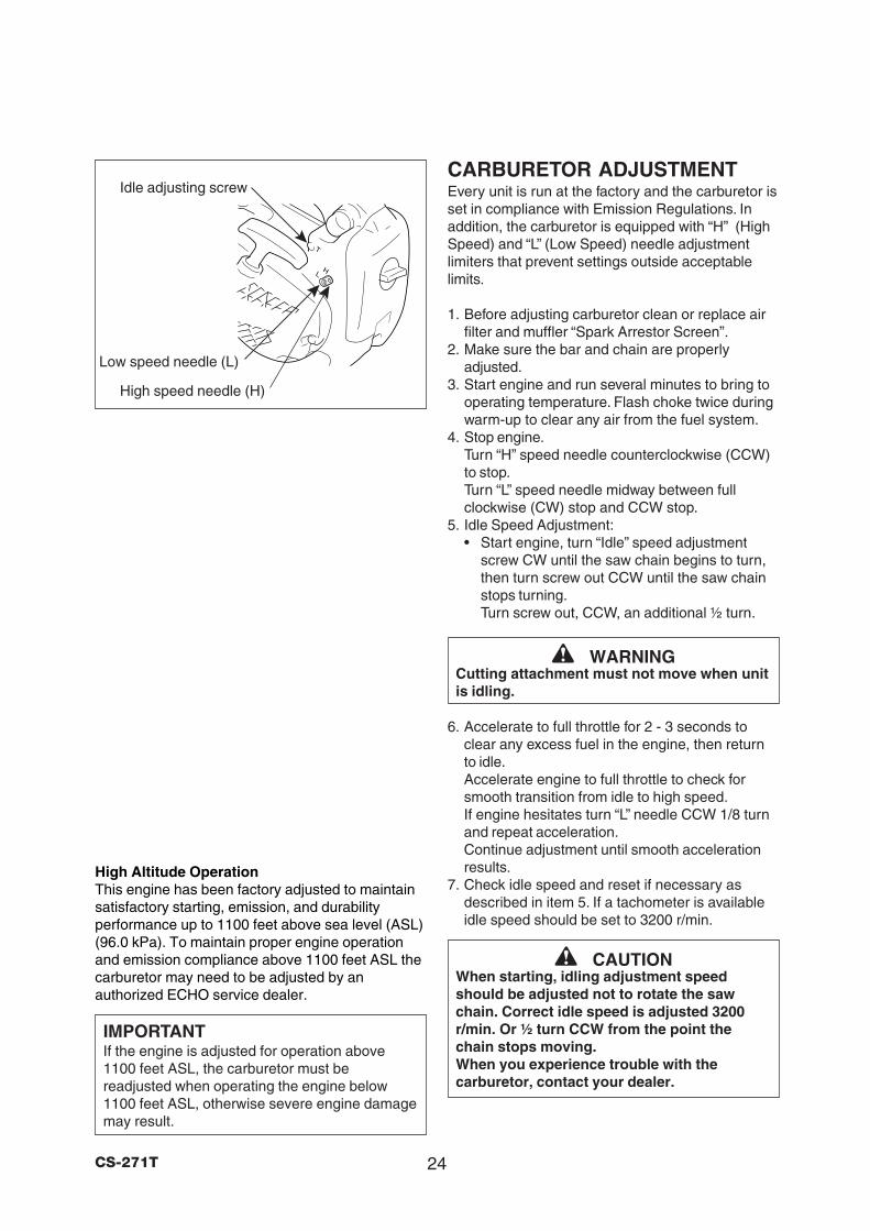
CARBURETOR ADJUSTMENTEvery unit is run at the factory and the carburetor isset in compliance with Emission Regulations. Inaddition, the carburetor is equipped with “H” (HighSpeed) and “L” (Low Speed) needle adjustmentlimiters that prevent settings outside acceptablelimits.
1. Before adjusting carburetor clean or replace airfilter and muffler “Spark Arrestor Screen”.
2. Make sure the bar and chain are properlyadjusted.
3. Start engine and run several minutes to bring tooperating temperature. Flash choke twice duringwarm-up to clear any air from the fuel system.
4. Stop engine.Turn “H” speed needle counterclockwise (CCW)to stop.Turn “L” speed needle midway between fullclockwise (CW) stop and CCW stop.
5. Idle Speed Adjustment:• Start engine, turn “Idle” speed adjustment
screw CW until the saw chain begins to turn,then turn screw out CCW until the saw chainstops turning.Turn screw out, CCW, an additional ½ turn.
6. Accelerate to full throttle for 2 - 3 seconds toclear any excess fuel in the engine, then returnto idle.Accelerate engine to full throttle to check forsmooth transition from idle to high speed.If engine hesitates turn “L” needle CCW 1/8 turnand repeat acceleration.Continue adjustment until smooth accelerationresults.
7. Check idle speed and reset if necessary asdescribed in item 5. If a tachometer is availableidle speed should be set to 3200 r/min.
WARNINGCutting attachment must not move when unitis idling.
CAUTIONWhen starting, idling adjustment speedshould be adjusted not to rotate the sawchain. Correct idle speed is adjusted 3200r/min. Or ½ turn CCW from the point thechain stops moving.When you experience trouble with thecarburetor, contact your dealer.
Idle adjusting screw
Low speed needle (L)
High speed needle (H)
High Altitude OperationThis engine has been factory adjusted to maintainsatisfactory starting, emission, and durabilityperformance up to 1100 feet above sea level (ASL)(96.0 kPa). To maintain proper engine operationand emission compliance above 1100 feet ASL thecarburetor may need to be adjusted by anauthorized ECHO service dealer.
IMPORTANTIf the engine is adjusted for operation above1100 feet ASL, the carburetor must bereadjusted when operating the engine below1100 feet ASL, otherwise severe engine damagemay result.
25 CS-271T
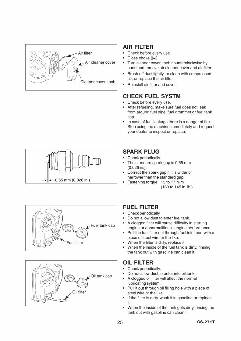
Oil filter
Fuel filter
Oil tank cap
Fuel tank cap
0.65 mm (0.026 in.)
Cleaner cover knob
Air filter
Air cleaner cover
AIR FILTER• Check before every use.• Close choke ( ).• Turn cleaner cover knob counterclockwise by
hand and remove air cleaner cover and air filter.
• Brush off dust lightly, or clean with compressedair, or replace the air filter.
• Reinstall air filter and cover.
CHECK FUEL SYSTM• Check before every use.• After refueling, make sure fuel does not leak
from around fuel pipe, fuel grommet or fuel tankcap.
• In case of fuel leakage there is a danger of fire.Stop using the machine immediately and requestyour dealer to inspect or replace.
SPARK PLUG• Check periodically.• The standard spark gap is 0.65 mm
(0.026 in.).• Correct the spark gap if it is wider or
narrower than the standard gap.• Fastening torque: 15 to 17 N·m
(130 to 145 in. lb.).
FUEL FILTER• Check periodically.• Do not allow dust to enter fuel tank.• A clogged filter will cause difficulty in starting
engine or abnormalities in engine performance.• Pull the fuel filter out through fuel inlet port with a
piece of steel wire or the like.• When the filter is dirty, replace it.• When the inside of the fuel tank is dirty, rinsing
the tank out with gasoline can clean it.
OIL FILTER• Check periodically.• Do not allow dust to enter into oil tank.• A clogged oil filter will affect the normal
lubricating system.• Pull it out through oil filling hole with a piece of
steel wire or the like.• If the filter is dirty, wash it in gasoline or replace
it.• When the inside of the tank gets dirty, rinsing the
tank out with gasoline can clean it.
26CS-271T
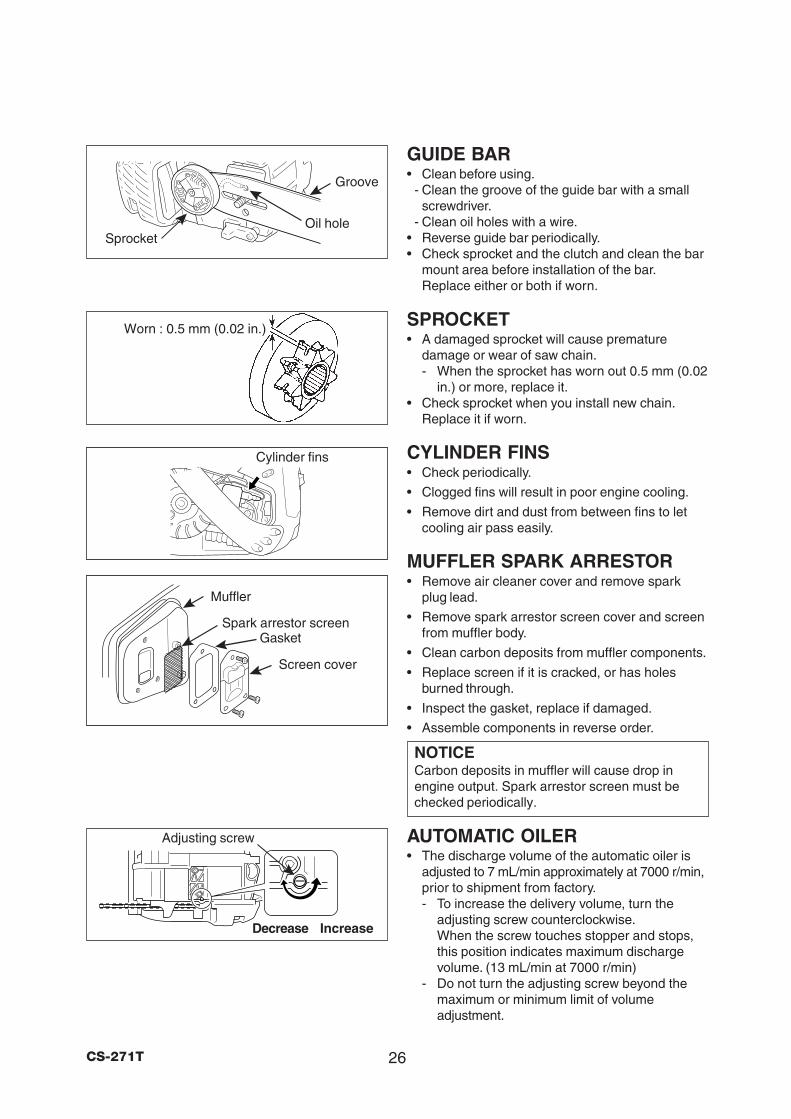
GUIDE BAR• Clean before using.
- Clean the groove of the guide bar with a smallscrewdriver.
- Clean oil holes with a wire.• Reverse guide bar periodically.• Check sprocket and the clutch and clean the bar
mount area before installation of the bar.Replace either or both if worn.
SPROCKET• A damaged sprocket will cause premature
damage or wear of saw chain.- When the sprocket has worn out 0.5 mm (0.02
in.) or more, replace it.• Check sprocket when you install new chain.
Replace it if worn.
CYLINDER FINS• Check periodically.
• Clogged fins will result in poor engine cooling.
• Remove dirt and dust from between fins to letcooling air pass easily.
MUFFLER SPARK ARRESTOR• Remove air cleaner cover and remove spark
plug lead.
• Remove spark arrestor screen cover and screenfrom muffler body.
• Clean carbon deposits from muffler components.
• Replace screen if it is cracked, or has holesburned through.
• Inspect the gasket, replace if damaged.
• Assemble components in reverse order.
NOTICECarbon deposits in muffler will cause drop inengine output. Spark arrestor screen must bechecked periodically.
AUTOMATIC OILER• The discharge volume of the automatic oiler is
adjusted to 7 mL/min approximately at 7000 r/min,prior to shipment from factory.- To increase the delivery volume, turn the
adjusting screw counterclockwise.When the screw touches stopper and stops,this position indicates maximum dischargevolume. (13 mL/min at 7000 r/min)
- Do not turn the adjusting screw beyond themaximum or minimum limit of volumeadjustment.
Worn : 0.5 mm (0.02 in.)
Groove
Oil hole
Cylinder fins
Spark arrestor screen
Muffler
Screen cover
Sprocket
Decrease Increase
Adjusting screw
Gasket
27 CS-271T
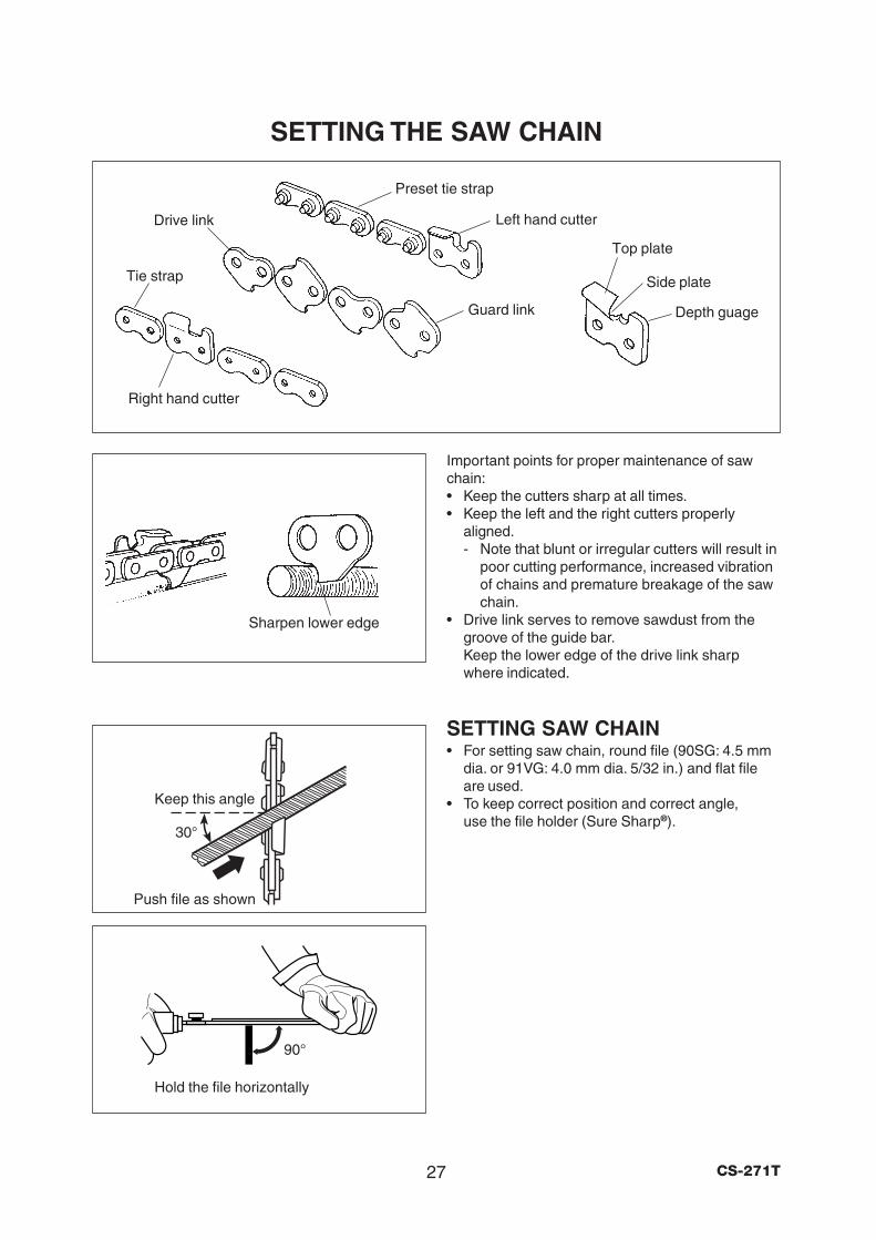
SETTING THE SAW CHAIN
Sharpen lower edge
Drive link
Tie strap
Right hand cutter
Preset tie strap
Left hand cutter
Guard link
Top plate
Side plate
Depth guage
Hold the file horizontally
90°
Important points for proper maintenance of sawchain:• Keep the cutters sharp at all times.• Keep the left and the right cutters properly
aligned.- Note that blunt or irregular cutters will result in
poor cutting performance, increased vibrationof chains and premature breakage of the sawchain.
• Drive link serves to remove sawdust from thegroove of the guide bar.Keep the lower edge of the drive link sharpwhere indicated.
SETTING SAW CHAIN• For setting saw chain, round file (90SG: 4.5 mm
dia. or 91VG: 4.0 mm dia. 5/32 in.) and flat fileare used.
• To keep correct position and correct angle,use the file holder (Sure Sharp®).
30°
Push file as shown
Keep this angle
28CS-271T
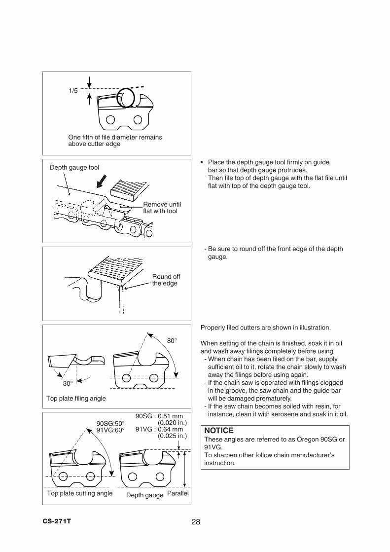
• Place the depth gauge tool firmly on guidebar so that depth gauge protrudes.Then file top of depth gauge with the flat file untilflat with top of the depth gauge tool.
- Be sure to round off the front edge of the depthgauge.
Properly filed cutters are shown in illustration.
When setting of the chain is finished, soak it in oiland wash away filings completely before using.
- When chain has been filed on the bar, supplysufficient oil to it, rotate the chain slowly to washaway the filings before using again.
- If the chain saw is operated with filings cloggedin the groove, the saw chain and the guide barwill be damaged prematurely.
- If the saw chain becomes soiled with resin, forinstance, clean it with kerosene and soak in it oil.
NOTICEThese angles are referred to as Oregon 90SG or91VG.To sharpen other follow chain manufacturer’sinstruction.
Remove untilflat with tool
Depth gauge tool
Round offthe edge
1/5
One fifth of file diameter remainsabove cutter edge
Top plate filing angle
80°
30°
Parallel
90SG : 0.51 mm(0.020 in.)
91VG : 0.64 mm(0.025 in.)
Top plate cutting angle Depth gauge
90SG:50°91VG:60°
29 CS-271T
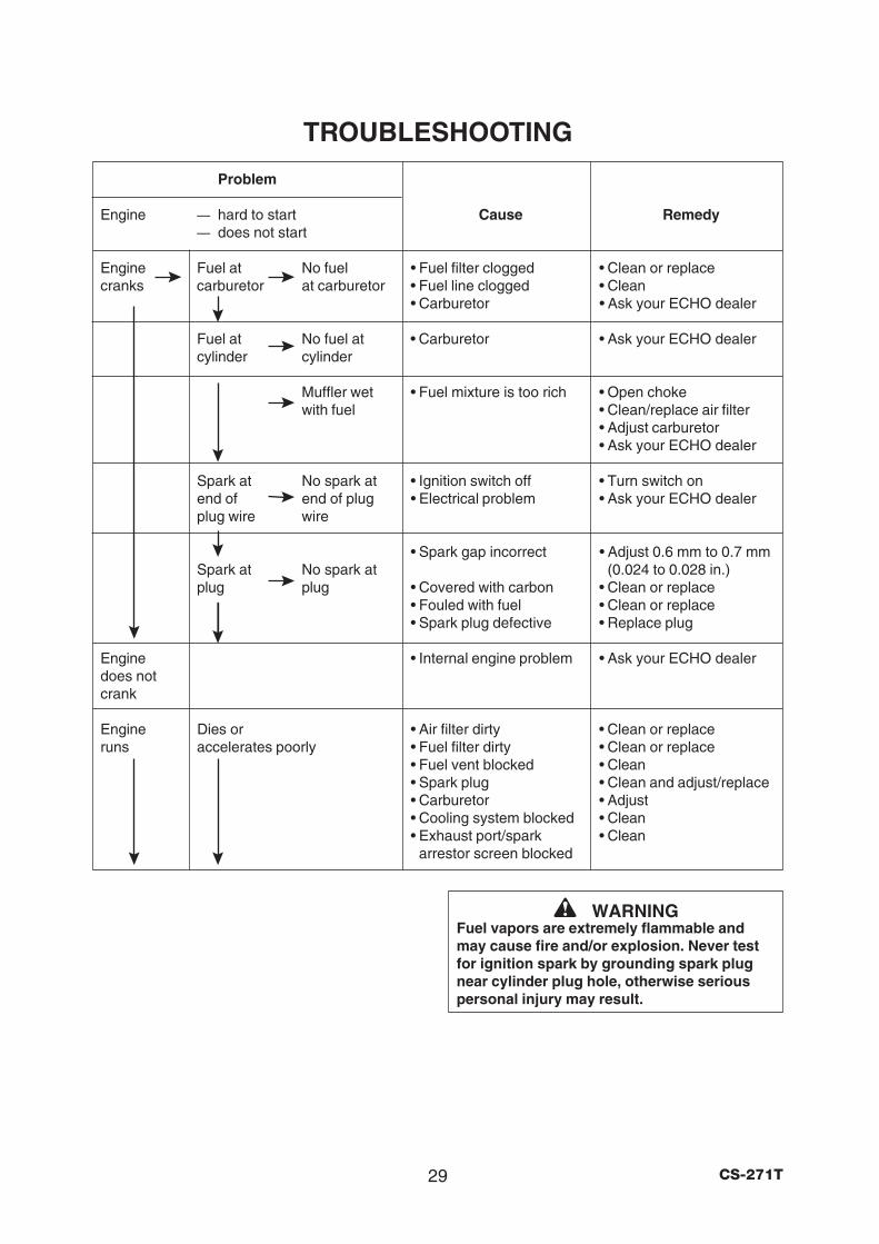
TROUBLESHOOTING
Problem
Engine — hard to start Cause Remedy— does not start
Engine Fuel at No fuel • Fuel filter clogged • Clean or replacecranks carburetor at carburetor • Fuel line clogged • Clean
• Carburetor • Ask your ECHO dealer
Fuel at No fuel at • Carburetor • Ask your ECHO dealercylinder cylinder
Muffler wet • Fuel mixture is too rich • Open chokewith fuel • Clean/replace air filter
• Adjust carburetor• Ask your ECHO dealer
Spark at No spark at • Ignition switch off • Turn switch onend of end of plug • Electrical problem • Ask your ECHO dealerplug wire wire
• Spark gap incorrect • Adjust 0.6 mm to 0.7 mmSpark at No spark at (0.024 to 0.028 in.)plug plug • Covered with carbon • Clean or replace
• Fouled with fuel • Clean or replace• Spark plug defective • Replace plug
Engine • Internal engine problem • Ask your ECHO dealerdoes notcrank
Engine Dies or • Air filter dirty • Clean or replaceruns accelerates poorly • Fuel filter dirty • Clean or replace
• Fuel vent blocked • Clean• Spark plug • Clean and adjust/replace• Carburetor • Adjust• Cooling system blocked • Clean• Exhaust port/spark • Clean
arrestor screen blocked
WARNINGFuel vapors are extremely flammable andmay cause fire and/or explosion. Never testfor ignition spark by grounding spark plugnear cylinder plug hole, otherwise seriouspersonal injury may result.
30CS-271T
STORAGE AFTER USE
* Technical data subject to change without notice.
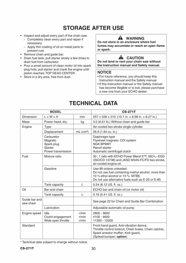
TECHNICAL DATA
• Inspect and adjust every part of the chain saw.- Completely clean every part and repair if
necessary.- Apply thin coating of oil on metal parts to
prevent rust.• Remove chain and guide bar.• Drain fuel tank, pull starter slowly a few times to
drain fuel from carburetor.• Pour a small amount of clean motor oil into spark
plug hole, pull starter and crank the engine untilpiston reaches: TOP DEAD CENTER.
• Store in a dry area, free from dust.
WARNINGDo not store in an enclosure where fuelfumes may accumlate or reach an open flameor spark.
CAUTIONDo not lend or rent your chain saw withoutthe Instruction manual and Safety manual.
NOTICE• For future reference, you should keep this
Instruction manual and the Safety manual.• If this Instruction manual or the Safety manual
has become illegible or is lost, please purchasea new one from your ECHO dealer.
MODEL CS-271T
Dimension L × W × H mm 257 × 228 × 210 (10.1 in. × 8.98 in. × 8.27 in.)
Mass Power head, dry kg 3.0 (6.61 lb.) Without chain and guide bar
Engine Type Air-cooled two-stroke single cylinder
Displacement mL (cm³) 26.9 (1.64 cu. in.)
Carburetor Diaphragm typeMagneto Flywheel magneto: CDI systemSpark plug NGK BPM8YStarter Recoil starterPower transmission Automatic centrifugal clutch
Fuel Mixture ratio 50 : 1 ratio with ECHO Power Blend X™, ISO-L- EGD(ISO/CD 13738) and JASO M345-FC/FD two-stroke,air-cooled engine oil.
Gasoline Use 89 octane unleaded.Do not use fuel containing methyl alcohol, more than10 % ethyl alcohol or 15 % MTBE.Do not use alternative fuels such as E-20 or E-85.
Tank capacity L 0.24 (8.12 US. fl. oz.)
Oil Bar and chain ECHO bar and chain oil (or motor oil)
Tank capacity L 0.16 (5.41 US. fl. oz.)
Guide bar and See page 22 for Chain and Guide Bar Combinationsaw chain
Lubrication Adjustable automatic oil pump
Engine speed Idle r/min 2800 - 3600Clutch engagement r/min 4100 - 4600Wide open throttle r/min 11300 - 12500
Standard Front hand guard, Anti-vibration device,Throttle control lockout, Chain brake, Chain catcher,Spark arrestor muffler, Kick guard,(Spiked bumper; option)
31 CS-271T
WARRANTY STATEMENTSECHO LIMITED WARRANTY STATEMENT FOR
PRODUCT SOLD IN USA AND CANADA BEGINNING 01/01/2010
ECHO’S RESPONSIBILITYECHO Incorporated’s Limited Warranty, provides to the original purchaser that this ECHO product is free from defects in materialand workmanship. Under normal use and maintenance from date of purchase, ECHO agrees to repair or replace at ECHO’sdiscretion, any defective product free of charge at any authorized ECHO servicing dealer within listed below application timeperiods, limitations and exclusions. THIS LIMITED WARRANTY IS ONLY APPLICABLE TO ECHO PRODUCTS SOLD BYAUTHORIZED ECHO DEALERS. IT IS EXTENDED TO THE ORIGINAL PURCHASER ONLY, AND IS NOT TRANSFERABLETO SUBSEQUENT OWNERS EXCEPT FOR EMISSION RELATED PARTS. Repair parts and accessories replaced under thiswarranty are warranted only for the balance of the original unit or accessory warranty period. Any damage caused by improperinstallation or improper maintenance is not covered by this warranty. All parts or products replaced under warranty become theproperty of ECHO, Inc. This warranty is separate from the Emission Control Warranty Statement supplied with your new product.Please consult the Emission Control Warranty Statement for details regarding emission related parts. For a list of AuthorizedECHO Dealers refer to WWW.ECHO-USA.COM or call 1-800-432-ECHO.
OWNER’S RESPONSIBILITYTo ensure trouble free warranty coverage it is important that you register your ECHO equipment on-line at WWW.ECHO-USA.COMor by filling out the warranty registration card supplied with your unit. Registering your product confirms your warranty coverageand provides a direct link if we find it necessary to contact you.
The owner shall demonstrate reasonable care and use, and follow preventative maintenance, storage, fuel and oil usage asprescribed in the operator’s manual. Should a product difficulty occur, you must, at your expense, deliver or ship your ECHO unit toan authorized ECHO servicing dealer for warranty repairs (within the applicable warranty period), and arrange for pick-up or returnof your unit after the repairs have been made. For your nearest authorized ECHO servicing dealer, call ECHO’s Dealer ReferralCenter, at 1-800-432-ECHO or you can locate an ECHO servicing dealer at WWW.ECHO-USA.COM. Should you requireassistance or have questions concerning ECHO’s Warranty Statement, you can contact our Consumer Product SupportDepartment at 1-800-673-1558 or contact us through the web at WWW.ECHO-USA.COM.
PRODUCT WARRANTY PERIOD
RESIDENTIAL APPLICATION• 5 YEAR WARRANTY - All units for residential, or non-income producing use will be covered by this limited warranty for five (5)
years from date of purchase.
EXCEPTIONS:• For two-stroke engine powered products, the electronic ignition module, flexible drive cables, SRM solid drive shafts, and TC
tines are warranted for the life* of the product on parts only.• Cutting attachments such as, but not limited to, bars, chains, sprockets, blades, and nylon trimmer heads for residential or non-
income producing use will be covered for failures due to defects in material or workmanship for a period of 60 days fromoriginal product purchase date. Any misuse from contact with concrete, rocks, or other structures is not covered by thiswarranty.
• ECHO’s Rapid Loader String Head carries a lifetime warranty on the line locking system, parts only; no labor. Refer to youroperator’s manual for string head installation and maintenance instructions.
• All SB-Series and PRO ATTACHMENT SERIES Split Shaft attachments carry the same warranty duration as the units they aredesigned to fit.
COMMERCIAL APPLICATION• 1 YEAR WARRANTY - All Chain Saws, QuikVent Saws, and Cut-Off Saws for commercial, institutional, agricultural, industrial, or
income producing use will be covered by this limited warranty for a period of one (1) year from the date of purchase.• 2 YEAR WARRANTY - All other units for commercial, institutional, agricultural, industrial, or income producing use will be
covered by this limited warranty for a period of two (2) years from the date of purchase.
EXCEPTIONS:• For two-stroke engine powered products, the electronic ignition module, flexible drive cables, SRM solid drive shafts and TC
tines, are warranted for the life* of the product on parts only.• Cutting attachments such as, but not limited to, bars, chains, sprockets, blades, and nylon trimmer heads for commercial,
institutional, agricultural, industrial, rental, or income producing will be covered for failures due to defects in material orworkmanship for a period of 30 days from original product purchase date. Any misuse from contact with concrete, rocks, orother structures is not covered by this warranty.
• ECHO’s Rapid Loader String Head carries a lifetime warranty on the line locking system, parts only; no labor. Refer to youroperator’s manual for string head installation and maintenance instructions.
• All SB-Series and PRO ATTACHMENT SERIES Split Shaft attachments carry the same warranty duration as the units they aredesigned to fit.
RENTAL APPLICATION - 90 DAYS WARRANTY• Units for rental use will be covered against defects in material and workmanship for a period of 90 days from the date of
purchase.
* ECHO’s liability under the “Lifetime” coverage is limited to furnishing parts specified under the PRODUCT WARRANTY PERIODsection of this Warranty Statement for “Life” free of charge for a period of ten (10) years after the date of the complete unit’s finalproduction.
32CS-271T
PURCHASED REPAIR PARTS, SHORT BLOCKS AND ACCESSORIES• 90-day residential, or non-income producing warranty• 30-day commercial, institutional, agricultural, industrial, income producing, or rental application warranty
ATTENTION TWO-STROKE ENGINE POWER PRODUCT OWNERSThis ECHO two-stroke engine power product is a quality-engineered unit which has been manufactured to exact tolerances toprovide superior performance. To help ensure the performance of the unit, it is required to use two-stroke oil which meets the ISO-L-EGD Standard per ISO/CD 13738 and JASO M345-FC/FD Standards. ECHO Power Blend X™ Two-Stroke Oil is a premiumtwo-stroke oil specifically formulated to meet ISO-L-EGD (ISO/CD 13738) and JASO M345-FC/FD Standards. The use of two-stroke oils designed for other applications, such as for outboard motors or lawnmowers can result in severe engine damage, andwill void your two-stroke engine limited warranty.
THIS WARANTY DOES NOT COVER DAMAGE CAUSED BY:• Lack of lubrication or engine failure, due to the use of two-stroke oils that do not meet the ISO-L-EGD (ISO/CD 13738) and JASO
M345-FC/FD Standards. Engine problems due to inadequate lubrication caused by failure to use an ISO-L-EGD compliant andJASO M345-FC/FD registered oil, will void the two-stroke engine limited warranty. ECHO Power Blend X™ Two-Stroke Oil meetsthe ISO-L-EGD and JASO M345-FC/FD Standard. Emission related parts are covered for 5 years residential use or 2 yearscommercial use regardless of two-stroke oil used, per the statement listed in the EPA or California Emission Defect WarrantyExplanation.
• Damage caused by use of gasohol, containing methanol (wood alcohol), or gasoline containing less than 89 octane. Only usegasoline which contains 89 octane or higher. Gasohol which contains a maximum 10 % ethanol (grain alcohol) or 15 % MTBE(methyl/tertiary/butyl/ether) is also approved. The prescribed mixing ratio of gasoline to oil is listed on the ECHO oil label andcovered in your operator’s manual.
• Engine damage caused by use of ether or any starting fluids.• Damage caused by tampering with engine speed governor or emission components, or running engines above specified and
recommended engine speeds as listed in your operator’s manual.• Operation of the unit with improperly maintained/removed cutting shield or removed/damaged air filter.• Damage caused by dirt, pressure or steam cleaning the unit, salt water, corrosion, rust, varnish, abrasives, and moisture.• Defects, malfunctions or failures resulting from abuse, misuse, neglect, modifications, alterations, normal wear, improper
servicing, or use of unauthorized attachments.• Incorrect storage procedures, stale fuel, including failure to provide or perform required maintenance services as prescribed in
the operator’s manual. Preventative maintenance as outlined in the operator’s manual is the customer’s responsibility.• Failures due to improper set-up, pre-delivery service or repair service by anyone other than authorized ECHO servicing dealer
during the warranty period.• Certain parts and other items are not warranted, including but not limited to: lubricants, starter cords, and engine tune-ups.• Use of spark plugs other than those meeting performance and durability requirements of the OEM spark plug listed in the
Operator’s Manuals.• Overheating or carbon scoring failures due to restricted, clogged exhaust port or combustion chamber, including damage to spark
arrester screen.• Adjustments after the first (30) thirty days and beyond, such as carburetor adjustment and throttle cable adjustment.• Damage to gears or gear cases caused by contaminated grease or oil, use of incorrect type or viscosity of lubricants, and/or
failure to comply with recommended grease or oil change intervals.• Damage caused by loading SHRED ‘N’ VAC® beyond recommended capacity.• Damage caused by pump or sprayer running dry, pumping or spraying caustic or flammable materials, or lack of or broken
strainers.• Additional damage to parts or components due to continued use after operational problem or failure occurs. Should operational
problem or failure occur, the product should not be used, but delivered as is to an authorized ECHO servicing dealer.
It is a dealer’s and/or customer’s responsibility to complete and return the warranty registration card supplied with your ECHOproduct or by visiting WWW.ECHO-USA.COM. Your receipt of purchase including date, model and serial number must bemaintained and presented to an authorized ECHO servicing dealer for warranty service. Proof of purchase rests solely with thecustomer. Some states do not allow limitations on how long an implied warranty lasts, so the above limitations may not apply toyou. Some states do not allow the exclusion or limitation of incidental or consequential damages, so you may also have otherspecific legal rights which vary from state to state. This limited warranty is given by ECHO Incorporated, 400 Oakwood Rd., LakeZurich, IL 60047.
DISCLAIMER OF IMPLIED WARANTIES
This limited warranty is in lieu of all other expressed or implied warranties, including any warranty of FITNESS FOR APARTICULAR PURPOSE OR USE and any implied warranty of MERCHANTABILITY otherwise applicable to this product. ECHOand its affiliated companies shall not be liable for any special incidental or consequential damage, including lost profits. There areno warranties extended other than as provided herein. This limited warranty may be modified only by ECHO.
33 CS-271T
ECHO INCORPORATED EMISSION CONTROL WARRANTY STATEMENT FOR ECHO BRAND
The Environmental Protection Agency (EPA) and the California Air Resources Board (C.A.R.B.) and ECHO Incorporated (ECHOInc.) are pleased to explain the emission control system warranty on your 2010 and later equipment/small off-road engine (SORE).New equipment/SORE must be designed, built and equipped to meet stringent EPA and C.A.R.B. anti-smog standards. ECHO Inc.must warrant the emission control system on your equipment/SORE for the periods of time listed below, provided there has beenno abuse, neglect or improper maintenance of your equipment/SORE. Your emission control system may include parts such as:carburetor, fuel-injection system, ignition system, catalytic converter/muffler, fuel tank, fuel feed lines, fuel cap assembly, sparkplug, air filters, and other associated components. Where a warrantable condition exists, ECHO Inc. will repair your equipment/SORE at no cost to you including diagnosis, parts and labor. The Emission Control System Warranty is extended to the originalowner including all subsequent owners.
MANUFACTURER’S WARRANTY COVERAGE:The emission control system is warranted for 2 years or the length of the ECHO Inc. warranty, whichever is longer. If any emission-related part on your equipment is defective, the part will be repaired or replaced by ECHO Inc. or its Authorized ServiceRepresentative.
OWNER’S WARRANTY RESPONSIBILITIES:As the equipment/SORE owner, you are responsible for the performance of the required maintenance listed in your Operator’sManual. ECHO Inc. recommends that you retain all receipts covering maintenance on your equipment/SORE however, ECHO Inc.cannot deny warranty solely for the lack of receipts or for your failure to ensure the performance of all scheduled maintenance. Asthe equipment/SORE owner, you should be aware that ECHO Inc. may deny you warranty coverage if your equipment/SORE or apart has failed due to abuse, neglect, improper maintenance or unapproved modifications.
You are responsible for presenting your equipment/SORE to an ECHO Inc. authorized service representative as soon as aproblem exists. The warranty repairs should be completed in a reasonable amount of time, not to exceed 30 days. If a warrantablecondition exists and there is no Authorized Dealer within 100 miles, ECHO Inc. will pay to ship the unit to the nearest authorizeddealer. If you have questions regarding your warranty coverage, you should contact ECHO Inc. at 1-800-673-1558, web siteWWW.ECHO-USA.COM.
WHAT DOES THIS WARRANTY COVER?ECHO Inc. warrants that your equipment/SORE was designed, built and equipped to conform with applicable EPA and C.A.R.B.emissions standards and that your equipment/SORE is free from defects in material and workmanship that would cause it to fail toconform with applicable requirements for 2 years or the length of the ECHO Inc. warranty, whichever is longer. The warranty periodbegins on the date the product is purchased by an end user.
HOW WILL A COVERED PART BE CORRECTED?If there is a defect in a part covered by this warranty, any ECHO Inc. Authorized Service Dealer will correct the defect. You will nothave to pay anything to have the part adjusted, repaired or replaced. This includes any labor and diagnosis for warranted repairsperformed by the dealer. In addition, engine parts not expressly covered under this warranty but whose failure is a result of afailure of a covered part will be warranted.
WHAT PARTS ARE COVERED?Any applicable emission related part not scheduled for “required maintenance” will be repaired or replaced within the warrantyperiod. The repaired or replaced part will be warranted for the remaining ECHO Inc. warranty period.
Any warranted part that is scheduled only for regular inspection in the written instructions supplied is warranted for the warrantyperiod stated above. Any such part repaired or replaced under warranty will be warranted for the remaining ECHO Inc. warrantyperiod.
Any emission related part scheduled for replacement during “required maintenance” is warranted for the period of time prior to thefirst scheduled replacement point for that part. Any such part repaired or replaced under warranty shall be warranted for theremainder of the period prior to the first scheduled replacement point for that part.
Any manufacturer-approved replacement part may be used in the performance of any warranty maintenance or repairs onemission related parts, and must be provided without charge if the part is still under warranty.
Any replacement part that is equivalent in performance and durability may be used in non-warranty maintenance or repairs, andshall not reduce the warranty obligations of the manufacturer.
Throughout the equipment/SORE warranty period, ECHO Inc. will maintain a supply of warranted parts sufficient to meet theexpected demand for such parts.
SPECIFIC EMISSION RELATED WARRANTED PARTS:• Electronic Ignition System • Spark Plug• Catalytic Converter / Muffler Assembly • Carburetor (complete assembly or replaceable components)• Choke • Fuel-Injection Assembly (or replaceable components)• Fuel Tank • Fuel Cap Assembly• Air Filter • Fuel Feed Line (and associated clamps/connectors as applicable)
WHAT IS NOT COVERED?Any failure caused by abuse, neglect, improper maintenance, unapproved modifications, use of unapproved add-on parts/modifiedparts or unapproved accessories.
This Emission Control Warranty is valid only for the U.S.A., it’s Territories, and Canada.