Embed Size (px)
Citation preview
X7503202807 X75000159711/06
WARNING DANGERRead rules for safe operation and instructions carefully. ECHO provides an Instruc-tion Manual and a Safety Manual. Both must be read and understood for proper and safe operation.
Chain SawInstruction Manual
MODELS : CS-301 CS-341 CS-346
2
Rules foR safe opeRationA. Kickback Safety Precaution for Chain Saw Users
B. Other Safety Precautions
1. Do not operate a chain saw with one hand! Serious injury to the operator, helpers, bystanders, or any combination of these persons may result from one-handed operation. A chain saw is intended for two-handed use.
2. Do not operate a chain saw when you are fatigued.
3. Use safety footwear; snug-fitting clothing; protective gloves; and eye, hearing and head protection devices. Wear protective hair cov-ering to contain long hair.
4. Use caution when handling fuel. Move the chain saw at least 3 m (10 feet) from the fuel-ing point before starting the engine.
5. Do not allow other persons to be near the chain saw when starting or cutting with the chain saw. Keep bystanders and animals out of the work area.
6. Do not start cutting until you have a clear work area, secure footing, and a planned retreat path from the falling tree.
7. Keep all parts of your body away from the saw chain when the engine is running.
8. Before you start the engine, make sure that the saw chain is not contacting anything.
Copyright© 2006 By Echo, IncorporatedAll Rights Reserved.
WARNING!KICKBACK may occur when the nose or tip of the guide bar touches an object, or when the wood closes in and pinches the saw chain in the cut.
Tip contact in some cases may cause a lightning fast reverse REACTION, Kicking the guide bar up and back towards the operator. Pinching the saw chain along the top of the guide bar may push the guide bar rapidly back towards the operator. Either of these reactions may cause you to lose control of the saw which could result in serious personal injury.
The Kick Guard ® device is not installed on the guide bar when you purchase your ECHO chain saw. The Kick Guard ® can be used in a majority of cutting operations, and is especially recom-mended for beginners, homeowners, or chain saw novices. Most cutting operations can be ac-complished with the Kick Guard® in place.
Do not rely exclusively upon the safety devices built into your saw. As a chain saw user, you should take several steps to keep your cutting jobs free from accident or injury.
1. With a basic understanding of kickback, you can reduce or eliminate the element of surprise. Sudden surprise contributes to ac-cidents.
2. Keep a good firm grip on the saw with both hands, the right hand on the rear handle, and the left hand on the front handle, when the engine is running. Use a firm grip with thumbs and fingers encircling the chain saw handles. A firm grip will help you reduce kickback and maintain control of the saw. Don’t’ let go.
3. Make sure that the area in which you are cut-ting is free from obstructions. Do not let the nose of the guide bar contact a log, branch, or any other obstruction which could be hit while you are operating the saw.
4. Cut at high engine speeds.
5. Do not overreach or cut above shoulder height.
6. Follow manufacturer’s sharpening and main-tenance instructions for the saw chain.
7. Only use replacement bars and chains speci-fied by the manufacturer or the equivalent.
3
9. Carry the chain saw with the engine stopped, the guide bar and saw chain to the rear, and the muffler away from your body.
10. Do not operate a chain saw that is damaged, improperly adjusted, or not completely and securely assembled. Be sure that the saw chain stops moving when the throttle control trigger is released.
11. Shut off the engine before setting the chain saw down.
12. Use extreme caution when cutting small size brush and saplings because slender material may catch the saw chain and be whipped toward you or pull you off balance.
13. When cutting a limb that is under tension, be alert for spring back so that you will not be struck when the tension in the wood fibers is released.
14. Keep the handles dry, clean, and free of oil or fuel mixture.
15. Operate the chain saw only in well-ventilated areas.
16. Do not operate a chain saw in a tree unless you have been specifically trained to do so.
17. All chain saw service, other than the items listed in the Instruction Manual mainte-nance instructions, should be performed by competent chain saw service personnel. (For example, if improper tools are used to remove the flywheel or if an improper tool is used to hold the flywheel in order to remove the clutch, structural damage to the flywheel could occur and could subsequently cause the flywheel to burst.)
18. When transporting your chain saw, use the appropriate guide bar scabbard.
19. Spark arrestor mufflers approved to SAE Standard J335b are Standard on ECHO Chain saws to reduce the possibility of for-est fires. Do not operate the chain saw with a loose or defective muffler. Do not remove the spark arrestor screen.
WARNING DANGER• During operation, the muffler or catalytic muffler and surrounding cover become hot.• Never suspend the saw on a lanyard with the engine running.• Always use the saw from the right-hand side of your body – NEVER from the left side.• Always wear proper safety clothing to protect your lower body from sharp saw chain and
hot muffler.• Always keep exhaust area clear of flammable debris during transportation or when storing,
otherwise serious property damage or personal injury may result.
WARNING DANGER Using improper replacement components or removing safety devices may result in serious or fatal injury.
4
ContentsPageRules for Safe Operation ..................................................................................................2Technical Data ..................................................................................................................5Emission Data ..................................................................................................................6Description........................................................................................................................6Nomenclature of Parts ......................................................................................................7Preparation for Use ..........................................................................................................9Fuel and Lubricant ..........................................................................................................10Operation ........................................................................................................................12Cutting Instructions .........................................................................................................14Maintenance and Care ...................................................................................................17Chain and Guide Bar Combinations ...............................................................................22Troubleshooting ..............................................................................................................24Storage ...........................................................................................................................25Correct Use of Chain Brake............................................................................................26Servicing Information ......................................................................................................28
4
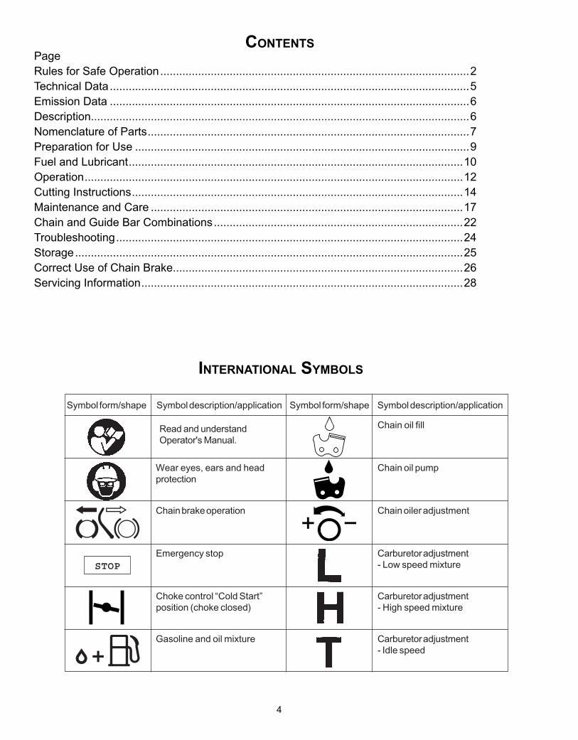
CONTENTS Page
Rules for Safe Operation .................................................................................................. 2Technical Data ................................................................................................................. 5Emission Data ................................................................................................................. 6Description ...................................................................................................................... 6Nomenclature of Parts ...................................................................................................... 7Preparation for Use .......................................................................................................... 8Fuel and Lubricant............................................................................................................ 9Operation ....................................................................................................................... 11Cutting Instructions ......................................................................................................... 13Maintenance and Care ................................................................................................... 16Chain and Guide Bar Combinations ............................................................................... 21Troubleshooting.............................................................................................................. 23Storage .......................................................................................................................... 24Correct Use of Chain Brake ........................................................................................... 26Servicing Information ...................................................................................................... 28
Carburetor adjustment- Idle speed
Carburetor adjustment- High speed mixture
Wear eyes, ears and headprotection
Carburetor adjustment- Low speed mixture
Gasoline and oil mixture
Symbol form/shape Symbol description/application Symbol form/shape Symbol description/application
Chain oiler adjustmentChain brake operation
Chain oil pump
Chain oil fill
Emergency stop
Choke control “Cold Start”position (choke closed)
STOP
INTERNATIONAL SYMBOLS
Read and understandOperator's Manual.
inteRnational symbols
5
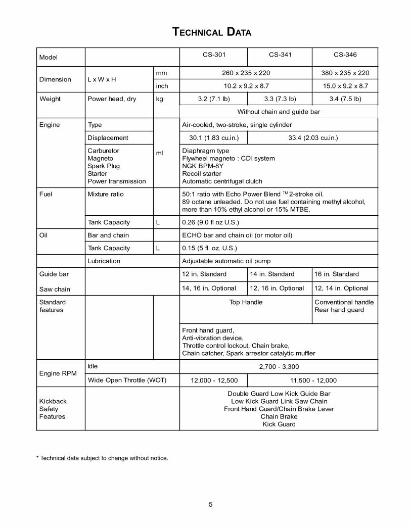
teChniCal Data
* Technical data subject to change without notice.
ledoM 103-SC 143-SC 643-SC
noisnemiD HxWxLmm 022x532x062 022x532x083
hcni 7.8x2.9x2.01 7.8x2.9x0.51
thgieW yrd,daehrewoP gk )bl1.7(2.3 )bl3.7(3.3 )bl5.7(4.3
rabediugdnaniahctuohtiW
enignE epyT
lm
rednilycelgnis,ekorts-owt,delooc-riA
tnemecalpsiD ).ni.uc38.1(1.03 ).ni.uc30.2(4.33
roterubraCotengaM
gulPkrapSretratS
noissimsnartrewoP
epytmgarhpaiDmetsysIDC:otengamleehwylF
Y8-MPBKGNretratslioceR
hctulclagufirtneccitamotuA
leuF oitarerutxiM dnelBrewoPohcEhtiwoitar1:05 MT .lioekorts-2,lohoclalyhtemgniniatnocleufesutonoD.dedaelnuenatco98
.EBTM%51rolohoclalyhte%01nahterom
yticapaCknaT L ).S.Uzolf0.9(62.0
liO niahcdnaraB )liorotomro(lioniahcdnarabOHCE
yticapaCknaT L ).S.U.zo.lf5(51.0
noitacirbuL pmupliocitamotuaelbatsujdA
rabediuG
niahcwaS
dradnatS.ni21 dradnatS.ni41 dradnatS.ni61
lanoitpO.ni61,41 lanoitpO.ni61,21 lanoitpO.ni41,21
dradnatSserutaef
eldnaHpoT eldnahlanoitnevnoCdraugdnahraeR
,draugdnahtnorF,ecivednoitarbiv-itnA
,ekarbniahC,tuokcollortnocelttorhTrelffumcitylatacrotserrakrapS,rehctacniahC
MPRenignEeldI 003,3-007,2
)TOW(elttorhTnepOediW 005,21-000,21 000,21-005,11
kcabkciKytefaS
serutaeF
raBediuGkciKwoLdrauGelbuoDniahCwaSkniLdrauGkciKwoL
reveLekarBniahC/drauGdnaHtnorFekarBniahC
drauGkciK
6
emission Data
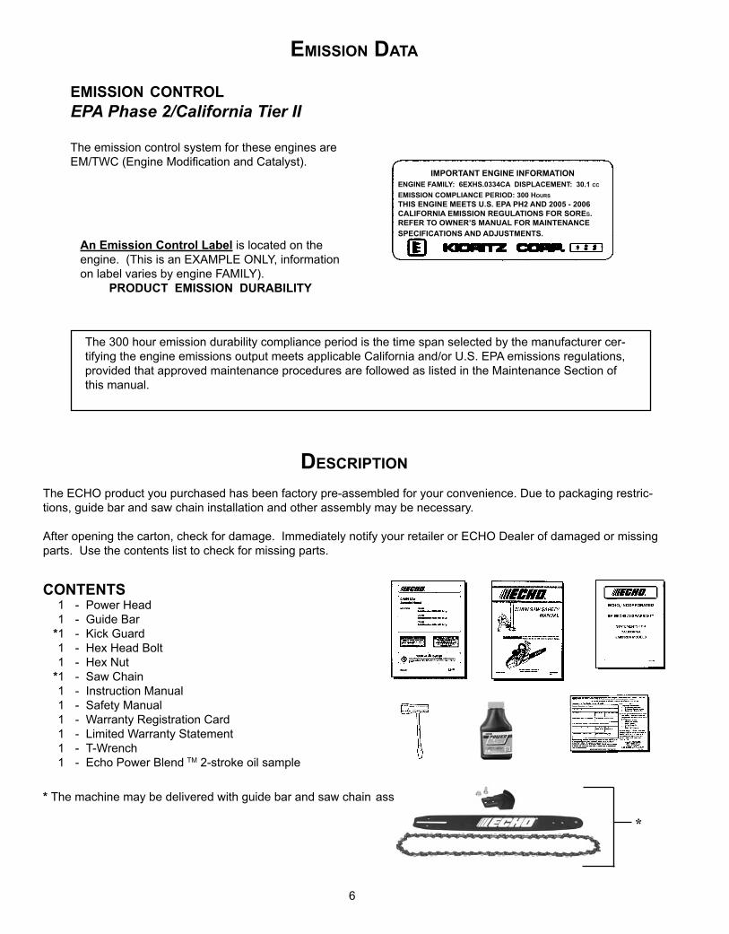
DesCRiption
The ECHO product you purchased has been factory pre-assembled for your convenience. Due to packaging restric-tions, guide bar and saw chain installation and other assembly may be necessary.
After opening the carton, check for damage. Immediately notify your retailer or ECHO Dealer of damaged or missing parts. Use the contents list to check for missing parts.
Contents 1 - Power Head 1 - Guide Bar *1 - Kick Guard 1 - Hex Head Bolt 1 - Hex Nut *1 - Saw Chain 1 - Instruction Manual 1 - Safety Manual 1 - Warranty Registration Card 1 - Limited Warranty Statement 1 - T-Wrench 1 - Echo Power Blend TM 2-stroke oil sample
* The machine may be delivered with guide bar and saw chain assembled.
impoRtant enGine infoRmationenGine family: 6eXhs.0334Ca DisplaCement: 30.1 CC
emission ComplianCe peRioD: 300 houRs
THIS ENGINE MEETS U.S. EPA PH2 AND 2005 - 2006 CALIFORNIA EMISSION REGULATIONS FOR SOREs. REFER TO OWNER’S MANUAL FOR MAINTENANCE SPECIFICATIONS AND ADJUSTMENTS.
emission ContRolEPA Phase 2/California Tier II The emission control system for these engines are EM/TWC (Engine Modification and Catalyst).
An Emission Control Label is located on the engine. (This is an EXAMPLE ONLY, information on label varies by engine FAMILY).
PRODUCT EMISSION DURABILITY
The 300 hour emission durability compliance period is the time span selected by the manufacturer cer-tifying the engine emissions output meets applicable California and/or U.S. EPA emissions regulations, provided that approved maintenance procedures are followed as listed in the Maintenance Section of this manual.
*
7
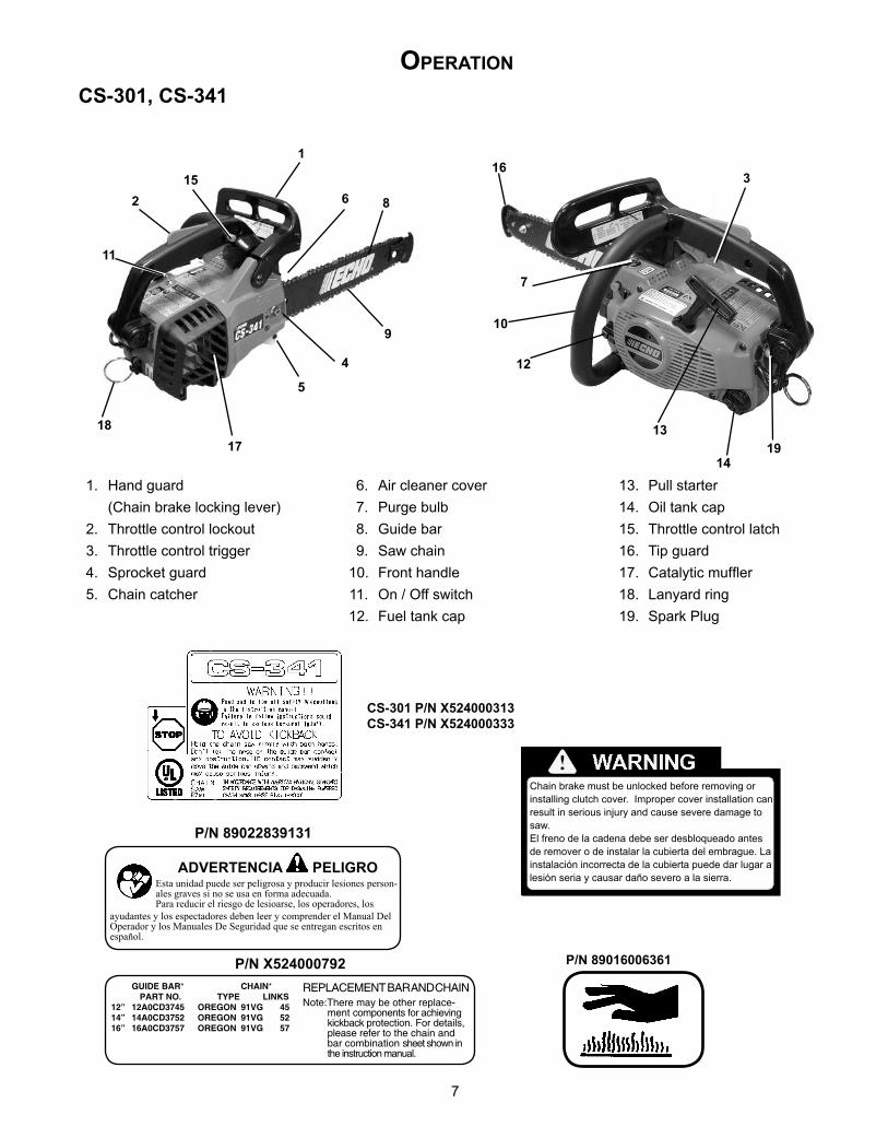
1. Hand guard (Chain brake locking lever) 2. Throttle control lockout 3. Throttle control trigger 4. Sprocket guard 5. Chain catcher
6. Air cleaner cover 7. Purge bulb 8. Guide bar 9. Saw chain 10. Front handle 11. On / Off switch 12. Fuel tank cap
13. Pull starter 14. Oil tank cap 15. Throttle control latch 16. Tip guard 17. Catalytic muffler 18. Lanyard ring19. Spark Plug
opeRation
ADVERTENCIA PELIGRO
P/N 89022839131
Esta unidad puede ser peligrosa y producir lesiones person-ales graves si no se usa en forma adecuada. Para reducir el riesgo de lesioarse, los operadores, los
ayudantes y los espectadores deben leer y comprender el Manual Del Operador y los Manuales De Seguridad que se entregan escritos en español.
REPLACEMENT BAR AND CHAINNote:There may be other replace-
ment components for achieving kickback protection. For details, please refer to the chain and bar combination sheet shown in the instruction manual.
P/N X524000792 GUIDE BAR* CHAIN* PART NO. TYPE LINKS12” 12A0CD3745 OREGON 91VG 4514” 14A0CD3752 OREGON 91VG 5216” 16A0CD3757 OREGON 91VG 57
P/N 89016006361
CS-301 P/N X524000313CS-341 P/N X524000333
Chain brake must be unlocked before removing or installing clutch cover. Improper cover installation can result in serious injury and cause severe damage to saw.El freno de la cadena debe ser desbloqueado antes de remover o de instalar la cubierta del embrague. La instalación incorrecta de la cubierta puede dar lugar a lesión seria y causar daño severo a la sierra.
1
2
3
4
5
6
7
8
910
11
12
13
14
1516
1718
19
CS-301, CS-341
8
CS-346
P/N 89022839131
P/N X524000792
WARNING ! !Read and follow all safety precautions in the Instruction manual. Failure to follow instruc-tions could result in serious personal injury.
CHAIN SAW 87G1IN ACCORDANCE WITH AMERICAN NATIONAL STANDARD SAFETY REQUIREMENTS FOR
TO AVOID KICKBACK1.Holdthechainsawfirmlywithboth
hands.2. Don’t let the nose of the guide bar
contact any obstruction.3. Tip contact may suddenly move the
guide bar upward and backward, which may cause serious injury.
P/N 90019130131
P/N 89011439134
P/N 89016006361 15
14
16
17
1813
19
CS-306
1 2
3
4
5
78
9
6
10
13
20
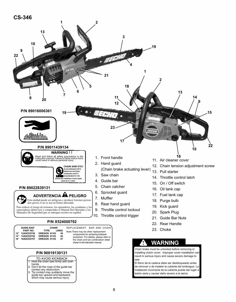
1. Front handle 2. Hand guard (Chain brake actuating lever) 3. Saw chain 4. Guide bar 5. Chain catcher 6. Sprocket guard 7. Muffler 8. Rear hand guard 9. Throttle control lockout 10. Throttle control trigger
1112
11. Air cleaner cover12. Chain tension adjustment screw13. Pull starter 14. Throttle control latch 15. On / Off switch16. Oil tank cap 17. Fuel tank cap 18. Purge bulb 19. Kick guard20. Spark Plug21. Guide Bar Nuts22. Rear Handle23. Choke
21
22
23
1
2
9
2210
19
ADVERTENCIA PELIGROEsta unidad puede ser peligrosa y producir lesiones person-ales graves si no se usa en forma adecuada.
Para reducir el riesgo de lesioarse, los operadores, los ayudantes y los espectadores deben leer y comprender el Manual Del Operador y los Manuales De Seguridad que se entregan escritos en español.
REPLACEMENT BAR AND CHAIN
Note:There may be other replacement components for achieving kickback protection. For details, please refer to the chain and bar combination sheet shown in the instruction manual.
GUIDE BAR* CHAIN* PART NO. TYPE LINKS12” 12A0CD3745 OREGON 91VG 4514” 14A0CD3752 OREGON 91VG 5216” 16A0CD3757 OREGON 91VG 57
GASOLINE POWERED CHAIN SAWS (ANSI B175.1-2000)
Chain brake must be unlocked before removing or installing clutch cover. Improper cover installation can result in serious injury and cause severe damage to saw.El freno de la cadena debe ser desbloqueado antes de remover o de instalar la cubierta del embrague. La instalación incorrecta de la cubierta puede dar lugar a lesión seria y causar daño severo a la sierra.
9
WARNINGIMPROPER CLUTCH COVER ASSEMBLY CAN RE-SULT IN SERIOUS INJURY, AND WILL CAUSE SE-VERE SAW DAMAGE IF UNIT IS STARTED. NEVER START OR OPERATE SAW IF BRAKE BAND IS NOT IN PLACE ON CLUTCH DRUM. ALWAYS CHECK CHAIN BRAKE OPERATION AFTER REPLACING COVER. DO NOT USE SAW IF CHAIN BRAKE DOES NOT FUNCTION PROPERLY.
pRepaRation foR use
H
I
J
7. Turn saw over and check brake band for correct posi-tion around clutch drum. If brake band is not in place around drum, remove clutch cover, make sure brake is released, and reinstall.
CAUTION!
• When starting, idling adjustment speed should be adjusted not to rotate the saw chain.
• When there is trouble with the carburetor, refer to your distributor or dealer.
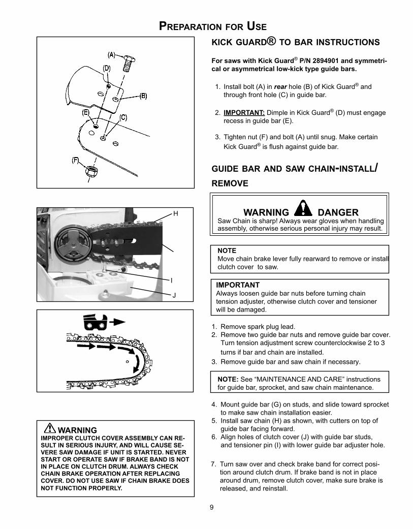
kiCk GuaRD® to baR instRuCtions
For saws with Kick Guard® P/N 2894901 and symmetri-cal or asymmetrical low-kick type guide bars.
1. Install bolt (A) in rear hole (B) of Kick Guard® and through front hole (C) in guide bar.
2. IMPORTANT: Dimple in Kick Guard® (D) must engage recess in guide bar (E).
3. Tighten nut (F) and bolt (A) until snug. Make certain Kick Guard® is flush against guide bar.
GuiDe baR anD saw Chain-install/Remove
WARNING DANGERSaw Chain is sharp! Always wear gloves when handling assembly, otherwise serious personal injury may result.
NOTEMove chain brake lever fully rearward to remove or install clutch cover to saw.
IMPORTANTAlways loosen guide bar nuts before turning chain tension adjuster, otherwise clutch cover and tensioner will be damaged.
1. Remove spark plug lead.2. Remove two guide bar nuts and remove guide bar cover.
Turn tension adjustment screw counterclockwise 2 to 3 turns if bar and chain are installed.
3. Remove guide bar and saw chain if necessary.
NOTE: See “MAINTENANCE AND CARE” instructions for guide bar, sprocket, and saw chain maintenance.
4. Mount guide bar (G) on studs, and slide toward sprocket to make saw chain installation easier.
5. Install saw chain (H) as shown, with cutters on top of guide bar facing forward.
6. Align holes of clutch cover (J) with guide bar studs, and tensioner pin (I) with lower guide bar adjuster hole.
10
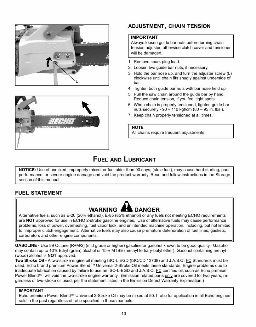
aDjustment, Chain tension
IMPORTANTAlways loosen guide bar nuts before turning chain tension adjuster, otherwise clutch cover and tensioner will be damaged.
1. Remove spark plug lead.2. Loosen two guide bar nuts, if necessary.3. Hold the bar nose up, and turn the adjuster screw (L)
clockwise until chain fits snugly against underside of bar.
4. Tighten both guide bar nuts with bar nose held up.5. Pull the saw chain around the guide bar by hand.
Reduce chain tension, if you feel tight spots.6. When chain is properly tensioned, tighten guide bar
nuts securely - 90 – 110 kgf/cm (80 – 95 in. lbs.).7. Keep chain properly tensioned at all times.
NOTEAll chains require frequent adjustments.
L
fuel anD lubRiCant
NOTICE: Use of unmixed, improperly mixed, or fuel older than 90 days, (stale fuel), may cause hard starting, poor performance, or severe engine damage and void the product warranty. Read and follow instructions in the Storage section of this manual.
fuel statement
WARNING DANGERAlternative fuels, such as E-20 (20% ethanol), E-85 (85% ethanol) or any fuels not meeting ECHO requirements are NOT approved for use in ECHO 2-stroke gasoline engines. Use of alternative fuels may cause performance problems, loss of power, overheating, fuel vapor lock, and unintended machine operation, including, but not limited to, improper clutch engagement. Alternative fuels may also cause premature deterioration of fuel lines, gaskets, carburetors and other engine components.
GASOLINE - Use 89 Octane [R+M/2] (mid grade or higher) gasoline or gasohol known to be good quality. Gasohol may contain up to 10% Ethyl (grain) alcohol or 15% MTBE (methyl tertiary-butyl ether). Gasohol containing methyl (wood) alcohol is NOT approved.Two Stroke Oil - A two-stroke engine oil meeting ISO-L-EGD (ISO/CD 13738) and J.A.S.O. FC Standards must be used. Echo brand premium Power Blend TM Universal 2-Stroke Oil meets these standards. Engine problems due to inadequate lubrication caused by failure to use an ISO-L-EGD and J.A.S.O. FC certified oil, such as Echo premium Power BlendTM, will void the two-stroke engine warranty. (Emission related parts only are covered for two years, re-gardless of two-stroke oil used, per the statement listed in the Emission Defect Warranty Explanation.)
IMPORTANT Echo premium Power BlendTM Universal 2-Stroke Oil may be mixed at 50:1 ratio for application in all Echo engines sold in the past regardless of ratio specified in those manuals.
11
Handling Fuel
WARNING DANGERFuel is VERY flammable. Use extreme care when mixing, storing or handling or serious personal injury may result.• Use an approved fuel container. • DO NOT smoke near fuel.• DO NOT allow flames or sparks near fuel.• Fuel tanks/cans may be under pressure. Always loosen
fuel caps slowly allowing pressure to equalize.• NEVER refuel a unit when the engine is HOT or RUN-
NING!• DO NOT fill fuel tanks indoors. ALWAYS fill fuel tanks
outdoors over bare ground.• DO NOT overfill fuel tank. Wipe up spills immediately.• Securely tighten fuel tank cap and close fuel container
after refueling.• Inspect for fuel leakage. If fuel leakage is found, do not
start or operate unit until leakage is repaired.• Move at least 3m (10 ft.) from refueling location before
starting the engine.
Mixing Instructions 1. Fill an approved fuel container with half of the required
amount of gasoline.2. Add the proper amount of 2-stroke oil to gasoline.3. Close container and shake to mix oil with gasoline.4. Add remaining gasoline, close fuel container, and remix.
IMPORTANT Spilled fuel is a leading cause of hydrocarbon emissions. Some states may require the use of automatic fuel shut-off containers to reduce fuel spillage.
After use• DO NOT store a unit with fuel in its tank. Leaks
can occur. Return unused fuel to an approved fuel storage container.
Storage - Fuel storage laws vary by locality. Contact your local government for the laws affecting your area. As a precaution, store fuel in an approved, airtight container. Store in a well-ventilated, unoccupied building, away from sparks and flames.
IMPORTANT Stored fuel ages. Do not mix more fuel than you expect to use in thirty (30) days, ninety (90) days when a fuel stabilizer is added.
IMPORTANT Stored two-stroke fuel may separate. ALWAYS shake fuel container thoroughly before each use.
Chain lubRiCantProper lubrication of the chain while in operation reduces fric-tion between the chain and the guide bar to a minimum and assures a longer service life.
• use bar and chain oil of high quality for this purpose.• Do not use used or reclaimed oil to avoid various oiler
problems.• Use ECHO bar and chain oil.• When ECHO bar and chain oil is not available:
Use motor oil, etc.• Use bar and chain oil of the following grades:
SAE NO. 30 ..... in summer SAE NO. 10 ..... in winter or when cutting resinous trees.
• When refueling, also refill chain oil.
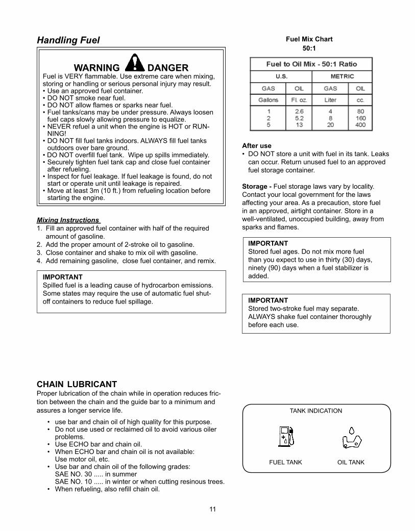
FUEL TANK OIL TANK
TANK INDICATION
Fuel Mix Chart50:1
12
CS-346
CS-301CS-341
AA
B
C
Securely hold the saw.
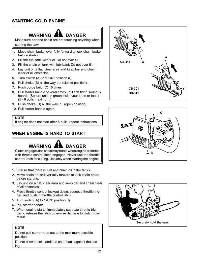
staRtinG ColD enGine
WARNING DANGERMake sure bar and chain are not touching anything when starting the saw.
1. Move chain brake lever fully forward to lock chain brake before starting.
2. Fill the fuel tank with fuel. Do not over fill.3. Fill the chain oil tank with lubricant. Do not over fill.4. Lay unit on a flat, clear area and keep bar and chain
clear of all obstacles.5. Turn switch (A) to “RUN” position (I).6. Pull choke (B) all the way out (closed position).7. Push purge bulb (C) 10 times.8. Pull starter handle several times until first firing sound is
heard. (Secure unit on ground with your knee or foot.) (5 - 6 pulls maximum.)
9. Push choke (B) all the way in. (open position)10. Pull starter handle again.
NOTEIf engine does not start after 5 pulls, repeat instructions.
when enGine is haRD to staRt
WARNING DANGERClutch engages and chain may rotate when engine is started with throttle control latch engaged. Never use the throttle control latch for cutting. Use only when starting the engine.
1. Ensure that there is fuel and chain oil in the tanks. 2. Move chain brake lever fully forward to lock chain brake
before starting. 3. Lay unit on a flat, clear area and keep bar and chain clear
of all obstacles. 4. Press throttle control lockout down, squeeze throttle trig-
ger, and push in throttle control latch.5. Turn switch (A) to “RUN” position (I).6. Pull starter handle.7. When engine starts, immediately squeeze throttle trig-
ger to release the latch otherwise damage to clutch may result.
NOTEDo not pull starter rope out to the maximum possible position.Do not allow recoil handle to snap back against the cas-ing.
13
CS-346
CS-301CS-341
AA
CS-346
CS-301CS-341
A A
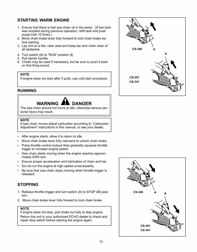
staRtinG waRm enGine1. Ensure that there is fuel and chain oil in the tanks. (If fuel tank
was emptied during previous operation, refill tank and push purge bulb 10 times.)
2. Move chain brake lever fully forward to lock chain brake be-fore starting.
3. Lay unit on a flat, clear area and keep bar and chain clear of all obstacles.
4. Turn switch (A) to “RUN” position (I).5. Pull starter handle.6. Choke may be used if necessary, but be sure to push it back
on first firing sound.
NOTEIf engine does not start after 5 pulls, use cold start procedure.
RunninG
WARNING DANGERThe saw chain should not move at idle, otherwise serious per-sonal injury may result.
NOTEIf saw chain moves adjust carburetor according to “Carburetor Adjustment” instructions in this manual, or see your dealer.
• After engine starts, allow it to return to idle.• Move chain brake lever fully rearward to unlock chain brake.• Press throttle control lockout then gradually squeeze throttle
trigger to increase engine speed.• Saw chain starts moving when the engine reaches approxi-
mately 4200 rpm.• Ensure proper acceleration and lubrication of chain and bar.• Do not run the engine at high speed unnecessarily.• Be sure that saw chain stops moving when throttle trigger is
released.
stoppinG1. Release throttle trigger and turn switch (A) to STOP (O) posi-
tion.2. Move chain brake lever fully forward to lock chain brake.
NOTEIf engine does not stop, pull choke out fully to stop engine.Return the unit to your authorized ECHO dealer to check and repair stop switch before starting the engine again.
14
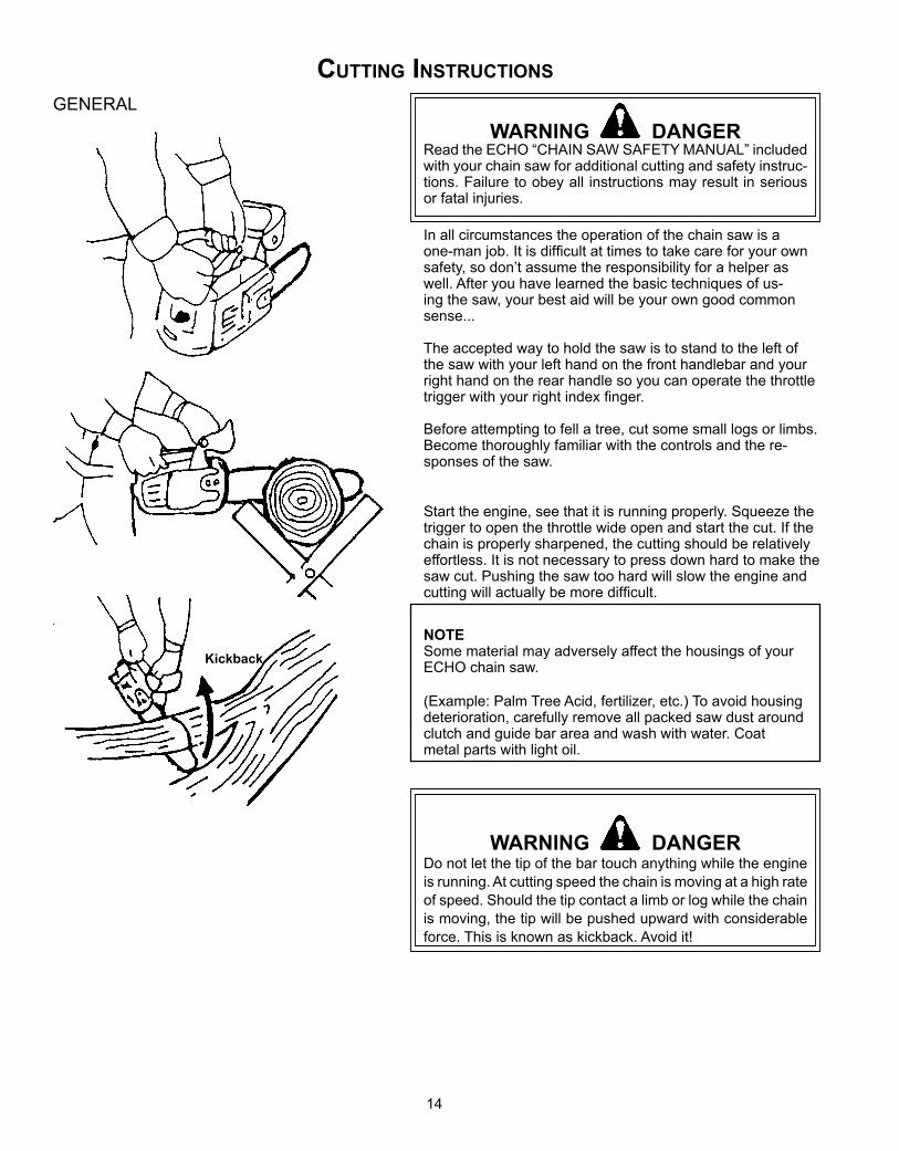
WARNING DANGERRead the ECHO “CHAIN SAW SAFETY MANUAL” included with your chain saw for additional cutting and safety instruc-tions. Failure to obey all instructions may result in serious or fatal injuries.
In all circumstances the operation of the chain saw is a one-man job. It is difficult at times to take care for your own safety, so don’t assume the responsibility for a helper as well. After you have learned the basic techniques of us-ing the saw, your best aid will be your own good common sense...
The accepted way to hold the saw is to stand to the left of the saw with your left hand on the front handlebar and your right hand on the rear handle so you can operate the throttle trigger with your right index finger.
Before attempting to fell a tree, cut some small logs or limbs. Become thoroughly familiar with the controls and the re-sponses of the saw.
Start the engine, see that it is running properly. Squeeze the trigger to open the throttle wide open and start the cut. If the chain is properly sharpened, the cutting should be relatively effortless. It is not necessary to press down hard to make the saw cut. Pushing the saw too hard will slow the engine and cutting will actually be more difficult.
NOTESome material may adversely affect the housings of your ECHO chain saw.
(Example: Palm Tree Acid, fertilizer, etc.) To avoid housing deterioration, carefully remove all packed saw dust around clutch and guide bar area and wash with water. Coat metal parts with light oil.
WARNING DANGERDo not let the tip of the bar touch anything while the engine is running. At cutting speed the chain is moving at a high rate of speed. Should the tip contact a limb or log while the chain is moving, the tip will be pushed upward with considerable force. This is known as kickback. Avoid it!
Kickback
CuttinG instRuCtions
GENERAL
15
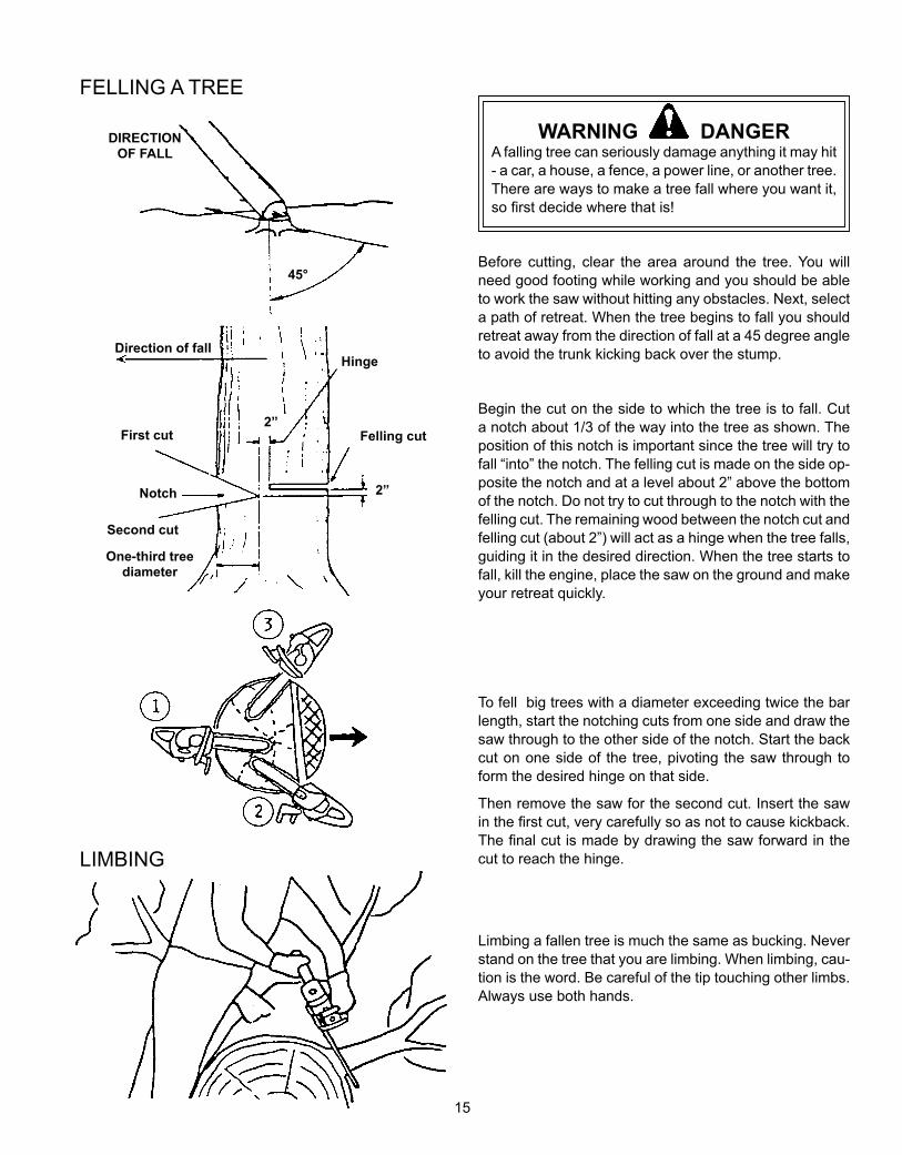
WARNING DANGERA falling tree can seriously damage anything it may hit - a car, a house, a fence, a power line, or another tree. There are ways to make a tree fall where you want it, so first decide where that is!
Before cutting, clear the area around the tree. You will need good footing while working and you should be able to work the saw without hitting any obstacles. Next, select a path of retreat. When the tree begins to fall you should retreat away from the direction of fall at a 45 degree angle to avoid the trunk kicking back over the stump.
Begin the cut on the side to which the tree is to fall. Cut a notch about 1/3 of the way into the tree as shown. The position of this notch is important since the tree will try to fall “into” the notch. The felling cut is made on the side op-posite the notch and at a level about 2” above the bottom of the notch. Do not try to cut through to the notch with the felling cut. The remaining wood between the notch cut and felling cut (about 2”) will act as a hinge when the tree falls, guiding it in the desired direction. When the tree starts to fall, kill the engine, place the saw on the ground and make your retreat quickly.
To fell big trees with a diameter exceeding twice the bar length, start the notching cuts from one side and draw the saw through to the other side of the notch. Start the back cut on one side of the tree, pivoting the saw through to form the desired hinge on that side.
Then remove the saw for the second cut. Insert the saw in the first cut, very carefully so as not to cause kickback. The final cut is made by drawing the saw forward in the cut to reach the hinge.
Limbing a fallen tree is much the same as bucking. Never stand on the tree that you are limbing. When limbing, cau-tion is the word. Be careful of the tip touching other limbs. Always use both hands.
2”
45°
2”
FELLING A TREE
DIRECTION OF FALL
Direction of fallHinge
Felling cutFirst cut
Notch
Second cut
One-third tree diameter
LIMBING
16
BUCKING
Uphill position
FINISH CUT
FIRST CUTBoard or flat stones
KICKBACK
• Improper thrust cutting.
• When the bar nose hits another tree, etc.
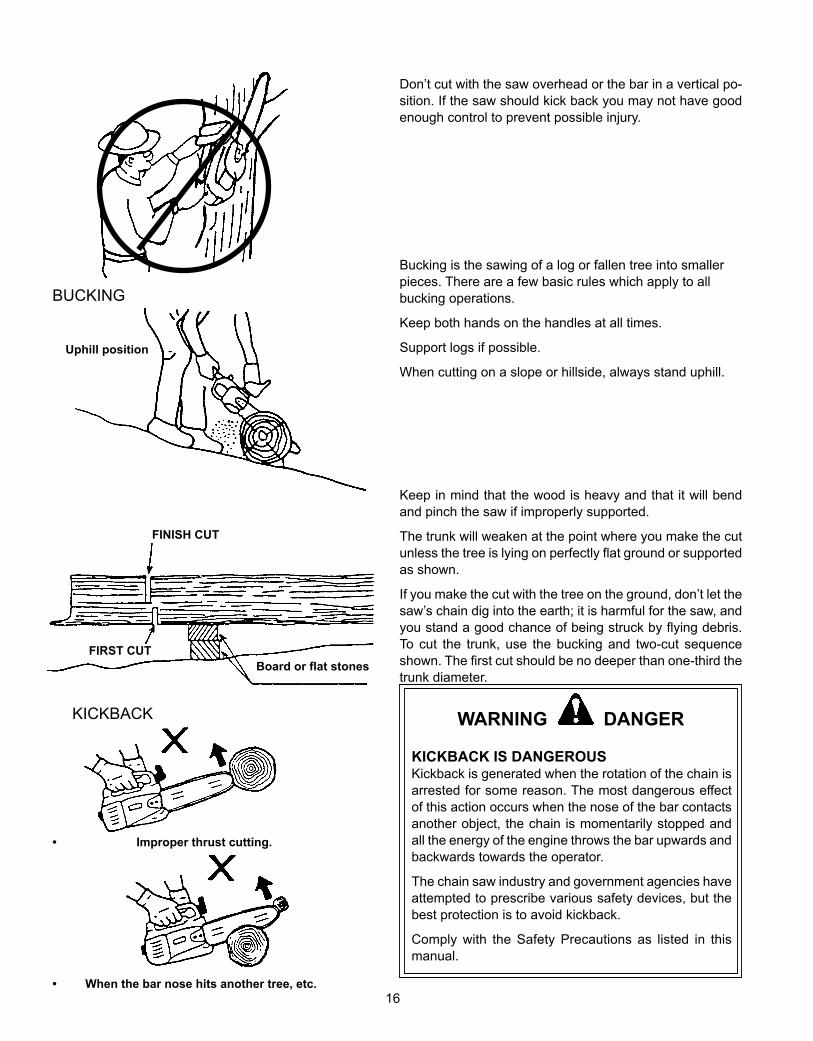
Don’t cut with the saw overhead or the bar in a vertical po-sition. If the saw should kick back you may not have good enough control to prevent possible injury.
Bucking is the sawing of a log or fallen tree into smaller pieces. There are a few basic rules which apply to all bucking operations.
Keep both hands on the handles at all times.
Support logs if possible.
When cutting on a slope or hillside, always stand uphill.
Keep in mind that the wood is heavy and that it will bend and pinch the saw if improperly supported.
The trunk will weaken at the point where you make the cut unless the tree is lying on perfectly flat ground or supported as shown.
If you make the cut with the tree on the ground, don’t let the saw’s chain dig into the earth; it is harmful for the saw, and you stand a good chance of being struck by flying debris. To cut the trunk, use the bucking and two-cut sequence shown. The first cut should be no deeper than one-third the trunk diameter.
WARNING DANGER
KICKBACK IS DANGEROUSKickback is generated when the rotation of the chain is arrested for some reason. The most dangerous effect of this action occurs when the nose of the bar contacts another object, the chain is momentarily stopped and all the energy of the engine throws the bar upwards and backwards towards the operator.
The chain saw industry and government agencies have attempted to prescribe various safety devices, but the best protection is to avoid kickback.
Comply with the Safety Precautions as listed in this manual.
17
COMPONENT/SYSTEM
MAINTENANCEPROCEDURE
REQ'DSKILLLEVEL
DAILY ORBEFORE
USE
EVERYREFUEL
3MONTHS
OR 90HOURS
6MONTHSOR 270HOURS
YEARLY600
HOURS
Recommended Echo Dealer Maintenance Procedures
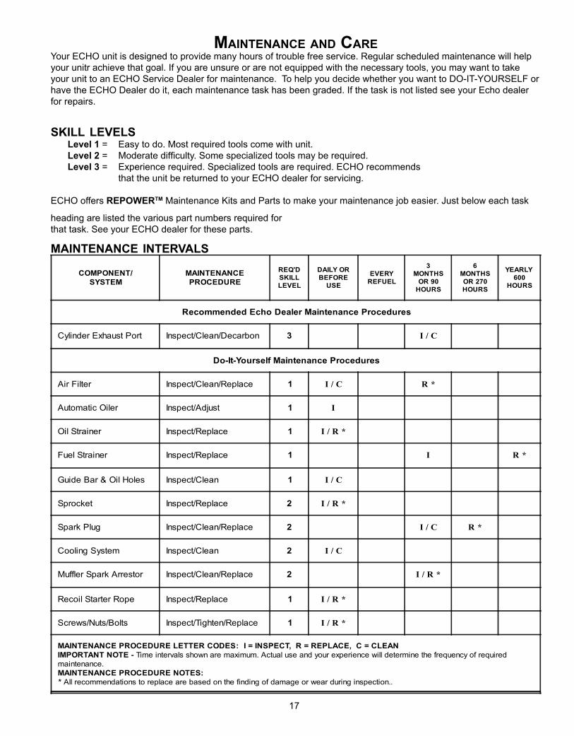
Cylinder Exhaust Port Inspect/Clean/Decarbon 3 I / C
Do-It-Yourself Maintenance Procedures
Air Filter Inspect/Clean/Replace 1 I / C R *
Automatic Oiler Inspect/Adjust 1 I
Oil Strainer Inspect/Replace 1 I / R *
Fuel Strainer Inspect/Replace 1 I R *
Guide Bar & Oil Holes Inspect/Clean 1 I / C
Sprocket Inspect/Replace 2 I / R *
Spark Plug Inspect/Clean/Replace 2 I / C R *
Cooling System Inspect/Clean 2 I / C
Muffler Spark Arrestor Inspect/Clean/Replace 2 I / R *
Recoil Starter Rope Inspect/Replace 1 I / R *
Screws/Nuts/Bolts Inspect/Tighten/Replace 1 I / R *
MAINTENANCE PROCEDURE LETTER CODES: I = INSPECT, R = REPLACE, C = CLEANIMPORTANT NOTE - Time intervals shown are maximum. Actual use and your experience will determine the frequency of requiredmaintenance.MAINTENANCE PROCEDURE NOTES:* All recommendations to replace are based on the finding of damage or wear during inspection..
maintenanCe anD CaReYour ECHO unit is designed to provide many hours of trouble free service. Regular scheduled maintenance will help your unitr achieve that goal. If you are unsure or are not equipped with the necessary tools, you may want to take your unit to an ECHO Service Dealer for maintenance. To help you decide whether you want to DO-IT-YOURSELF or have the ECHO Dealer do it, each maintenance task has been graded. If the task is not listed see your Echo dealer for repairs.
skill levels Level 1 = Easy to do. Most required tools come with unit. Level 2 = Moderate difficulty. Some specialized tools may be required. Level 3 = Experience required. Specialized tools are required. ECHO recommends that the unit be returned to your ECHO dealer for servicing.
ECHO offers REPOWERTM Maintenance Kits and Parts to make your maintenance job easier. Just below each task
heading are listed the various part numbers required for that task. See your ECHO dealer for these parts.
maintenanCe inteRvals
18
A
B
C
D
E
F
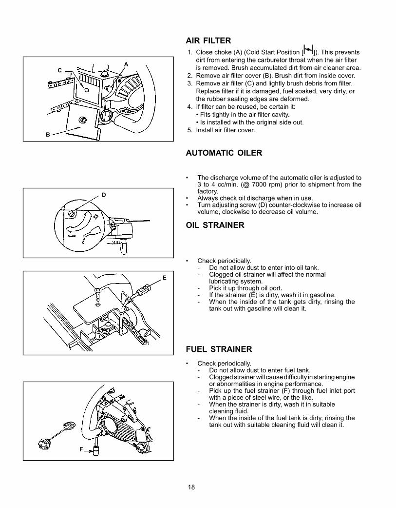
aiR filteR1. Close choke (A) (Cold Start Position [ ]). This prevents
dirt from entering the carburetor throat when the air filter is removed. Brush accumulated dirt from air cleaner area.
2. Remove air filter cover (B). Brush dirt from inside cover.3. Remove air filter (C) and lightly brush debris from filter.
Replace filter if it is damaged, fuel soaked, very dirty, or the rubber sealing edges are deformed.
4. If filter can be reused, be certain it: • Fits tightly in the air filter cavity. • Is installed with the original side out.5. Install air filter cover.
automatiC oileR
• The discharge volume of the automatic oiler is adjusted to 3 to 4 cc/min. (@ 7000 rpm) prior to shipment from the factory.
• Always check oil discharge when in use.• Turn adjusting screw (D) counter-clockwise to increase oil
volume, clockwise to decrease oil volume.
oil stRaineR
• Check periodically.- Do not allow dust to enter into oil tank.
- Clogged oil strainer will affect the normal lubricating system. - Pick it up through oil port. - If the strainer (E) is dirty, wash it in gasoline. - When the inside of the tank gets dirty, rinsing the
tank out with gasoline will clean it.
fuel stRaineR• Check periodically.
- Do not allow dust to enter fuel tank. - Clogged strainer will cause difficulty in starting engine
or abnormalities in engine performance. - Pick up the fuel strainer (F) through fuel inlet port
with a piece of steel wire, or the like. - When the strainer is dirty, wash it in suitable cleaning fluid. - When the inside of the fuel tank is dirty, rinsing the
tank out with suitable cleaning fluid will clean it.
19
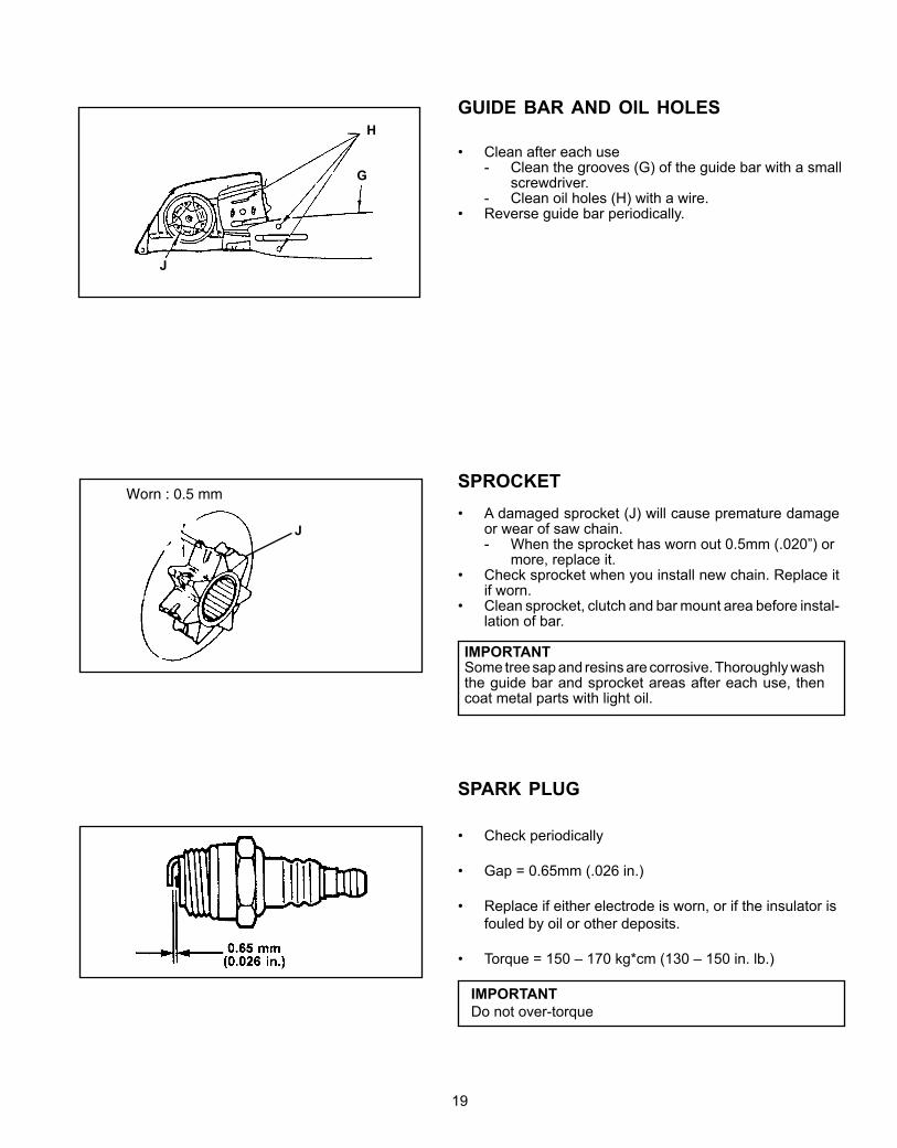
spRoCket• A damaged sprocket (J) will cause premature damage
or wear of saw chain.- When the sprocket has worn out 0.5mm (.020”) or more, replace it.
• Check sprocket when you install new chain. Replace it if worn.
• Clean sprocket, clutch and bar mount area before instal-lation of bar.
IMPORTANTSome tree sap and resins are corrosive. Thoroughly wash the guide bar and sprocket areas after each use, then coat metal parts with light oil.
• Check periodically
• Gap = 0.65mm (.026 in.)
• Replace if either electrode is worn, or if the insulator is fouled by oil or other deposits.
• Torque = 150 – 170 kg*cm (130 – 150 in. lb.)
IMPORTANT Do not over-torque
spaRk pluG
Worn : 0.5 mm
J
G
H
J
GuiDe baR anD oil holes
• Clean after each use- Clean the grooves (G) of the guide bar with a small screwdriver.
- Clean oil holes (H) with a wire.• Reverse guide bar periodically.
20
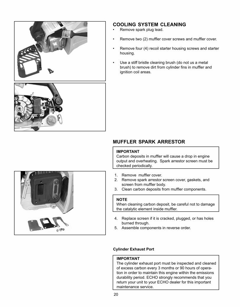
muffleR spaRk aRRestoR
IMPORTANT Carbon deposits in muffler will cause a drop in engine output and overheating. Spark arrestor screen must be checked periodically.
1. Remove muffler cover. 2. Remove spark arrestor screen cover, gaskets, and
screen from muffler body. 3. Clean carbon deposits from muffler components.
NOTEWhen cleaning carbon deposit, be careful not to damage the catalytic element inside muffler.
4. Replace screen if it is cracked, plugged, or has holes burned through.
5. Assemble components in reverse order.
CoolinG system CleaninG• Remove spark plug lead.
• Remove two (2) muffler cover screws and muffler cover.
• Remove four (4) recoil starter housing screws and starter housing.
• Use a stiff bristle cleaning brush (do not us a metal brush) to remove dirt from cylinder fins in muffler and ignition coil areas.
Cylinder Exhaust Port
IMPORTANTThe cylinder exhaust port must be inspected and cleaned of excess carbon every 3 months or 90 hours of opera-tion in order to maintain this engine within the emissions durability period. ECHO strongly recommends that you return your unit to your ECHO dealer for this important maintenance service.
21
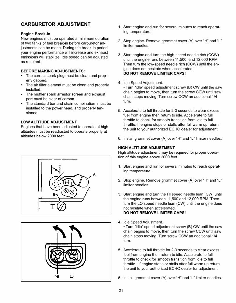
CaRbuRetoR aDjustment
Engine Break-InNew engines must be operated a minimum duration of two tanks of fuel break-in before carburetor ad-justments can be made. During the break-in period your engine performance will increase and exhaust emissions will stabilize. Idle speed can be adjusted as required.
BEFORE MAKING ADJUSTMENTS:• The correct spark plug must be clean and prop-
erly gapped.• The air filter element must be clean and properly
installed.• The muffler spark arrestor screen and exhaust
port must be clear of carbon.• The standard bar and chain combination must be
installed to the power head, and properly ten-sioned.
LOW ALTITUDE ADJUSTMENTEngines that have been adjusted to operate at high altitudes must be readjusted to operate properly at altitudes below 2000 feet.
B
A
1. Start engine and run for several minutes to reach operat-ing temperature.
2. Stop engine. Remove grommet cover (A) over “H” and “L” limiter needles.
3. Start engine and turn the high-speed needle rich (CCW) until the engine runs between 11,500 and 12,000 RPM. Then turn the low-speed needle rich (CCW) until the en-gine does not hesitate when accelerated.
DO NOT REMOVE LIMITER CAPS!
4. Idle Speed Adjustment. • Turn “idle” speed adjustment screw (B) CW until the saw
chain begins to move, then turn the screw CCW until saw chain stops moving. Turn screw CCW an additional 1/4 turn.
5. Accelerate to full throttle for 2-3 seconds to clear excess fuel from engine then return to idle. Accelerate to full throttle to check for smooth transition from idle to full throttle. If engine stops or stalls after full warm up return the unit to your authorized ECHO dealer for adjustment.
6. Install grommet cover (A) over “H” and “L” limiter needles.
HIGH ALTITUDE ADJUSTMENT High altitude adjustment may be required for proper opera-tion of this engine above 2000 feet.
1. Start engine and run for several minutes to reach operat-ing temperature.
2. Stop engine. Remove grommet cover (A) over “H” and “L” limiter needles.
3. Start engine and turn the HI speed needle lean (CW) until the engine runs between 11,500 and 12,000 RPM. Then turn the LO speed needle lean (CW) until the engine does not hesitate when accelerated.
DO NOT REMOVE LIMITER CAPS!
4. Idle Speed Adjustment. • Turn “idle” speed adjustment screw (B) CW until the saw
chain begins to move, then turn the screw CCW until saw chain stops moving. Turn screw CCW an additional 1/4 turn.
5. Accelerate to full throttle for 2-3 seconds to clear excess fuel from engine then return to idle. Accelerate to full throttle to check for smooth transition from idle to full throttle. If engine stops or stalls after full warm up return the unit to your authorized ECHO dealer for adjustment.
6. Install grommet cover (A) over “H” and “L” limiter needles.
22
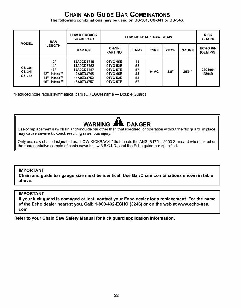
*Reduced nose radius symmetrical bars (OREGON name — Double Guard)
IMPORTANTChain and guide bar gauge size must be identical. Use Bar/Chain combinations shown in table above.
IMPORTANTIf your kick guard is damaged or lost, contact your Echo dealer for a replacement. For the name of the Echo dealer nearest you, Call: 1-800-432-ECHO (3246) or on the web at www.echo-usa.com.
Refer to your Chain Saw Safety Manual for kick guard application information.
Chain anD GuiDe baR CombinationsThe following combinations may be used on CS-301, CS-341 or CS-346.
WARNING DANGERUse of replacement saw chain and/or guide bar other than that specified, or operation without the “tip guard” in place, may cause severe kickback resulting in serious injury.
Only use saw chain designated as, “LOW-KICKBACK,” that meets the ANSI B175.1-2000 Standard when tested on the representative sample of chain saws below 3.8 C.I.D., and the Echo guide bar specified.
LEDOMRAB
HTGNEL
KCABKCIKWOLRABDRAUG
NIAHCWASKCABKCIKWOLKCIK
DRAUG
N/PRABNIAHC
.ONTRAPSKNIL EPYT HCTIP EGUAG
N/POHCE)N/PMEO(
103-SC143-SC643-SC
"21"41"61
znetnI"21 MT
znetnI"41 MT
"61 znetnI MT
5473DC0A212573DC0A417573DC0A615473DZ0A212573DZ0A417573DZ0A61
E54-GV19E25-GV19E75-GV19E54-GV19E25-GV19E75-GV19
542575542575
GV19 "8/3 "050.1094982
94982
23
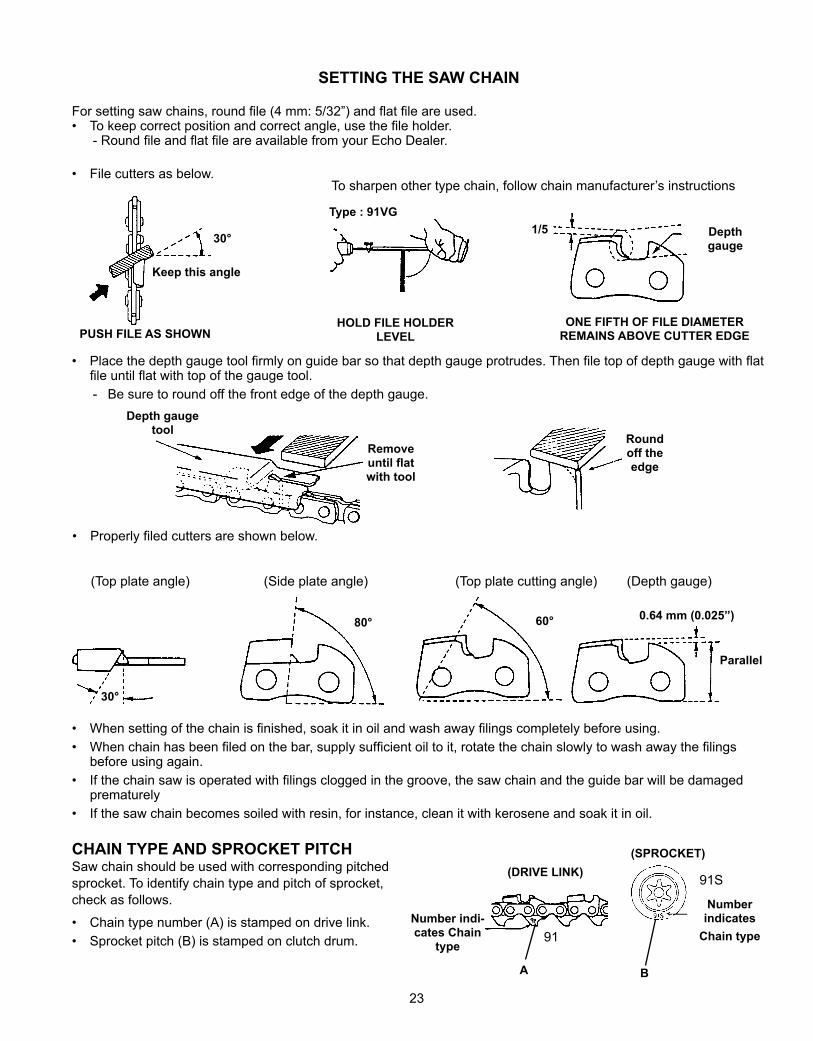
SETTING THE SAW CHAIN
For setting saw chains, round file (4 mm: 5/32”) and flat file are used.• To keep correct position and correct angle, use the file holder.
- Round file and flat file are available from your Echo Dealer.
• File cutters as below.
Type : 91VG
HOLD FILE HOLDER LEVEL
Depth gauge
ONE FIFTH OF FILE DIAMETER REMAINS ABOVE CUTTER EDGE
To sharpen other type chain, follow chain manufacturer’s instructions
30°
PUSH FILE AS SHOWN
Keep this angle
1/5
30°
80° 60° 0.64 mm (0.025”)
Parallel
• Properly filed cutters are shown below.
(Top plate angle) (Side plate angle) (Top plate cutting angle) (Depth gauge)
• When setting of the chain is finished, soak it in oil and wash away filings completely before using.• When chain has been filed on the bar, supply sufficient oil to it, rotate the chain slowly to wash away the filings
before using again.• If the chain saw is operated with filings clogged in the groove, the saw chain and the guide bar will be damaged
prematurely• If the saw chain becomes soiled with resin, for instance, clean it with kerosene and soak it in oil.
• Place the depth gauge tool firmly on guide bar so that depth gauge protrudes. Then file top of depth gauge with flat file until flat with top of the gauge tool.- Be sure to round off the front edge of the depth gauge.
Depth gauge tool
Remove until flat with tool
Round off the edge
91Number indi-cates Chain
type
Number indicates
Chain type
91S
(SPROCKET)(DRIVE LINK)
CHAIN TYPE AND SPROCKET PITCHSaw chain should be used with corresponding pitched sprocket. To identify chain type and pitch of sprocket, check as follows.
• Chain type number (A) is stamped on drive link.• Sprocket pitch (B) is stamped on clutch drum.
A B
24
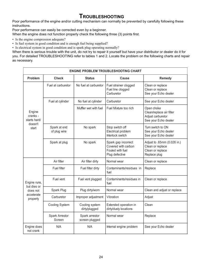
tRoubleshootinGPoor performance of the engine and/or cutting mechanism can normally be prevented by carefully following these instructions.Poor performance can easily be corrected even by a beginner.When the engine does not function properly check the following three (3) points first.• Istheenginecompressionadequate?• Isfuelsystemingoodconditionandisenoughfuelbeingsupplied?• Iselectricalsystemingoodconditionandissparkplugoperatingnormally?When there is serious trouble with the unit, do not try to repair it yourself but have your distributor or dealer do it for you. For detailed TROUBLESHOOTING refer to tables 1 and 2. Locate the problem on the following charts and repair as necessary.
reaching carburetor
Fuel is not reaching cylinderNo spark at high tension cord end.
Eng
ine
does
not
sta
rt (o
r, is
diffi
cult
to s
tart)
Eng
ine
cran
ks
Ther
e is
fuel
in th
e ta
nk
Fuel
is re
achi
ng c
arbu
reto
r
Fuel
is re
achi
ng c
ylin
der
Ther
e is
spa
rk a
t hig
h te
nsio
n co
rd e
nd
Ther
e is
spa
rk a
t plu
g
Sta
rting
pro
cedu
res
corr
ect
No spark at plugFuel does not keep running
Acceleration and low speed function defective
Carburetor overflowEngine does
not crankFuel strainer clogged ..........Clean.Fuel pipe
clogged ............Clean.
Suction insuf-ficient ................
Make sufficient.Strainer clogged ..........................................Clean.Carburetor out of order ................................Disassemble and check.C.D.I. module defective ...............................Remove and replace.
Ignition coil defective ...................................Remove and replace.Wire connection defective ..........................Reconnect.
High-tension cord connection defective.......Repair as necessary.
Switch is grounded ......................................Switch on.Insulator cracked .........................................Replace plug.
Spark gap incorrect .....................................Adjust.
Covered with carbon....................................Clean or replace.
Fouled with fuel ...........................................Clean or replace.Starting procedures incorrect ......................Start correctly.Low and high speed needle.........................Readjust.setting too lean Metering lever spring too strong ..................Readjust.
Fuel pump diaphragm defective ..................Replace.Fuel passage clogged with dust ..................Disassemble and clean.
Fuel leaking from fixing surfaces ................Retighten all screws. of carburetor
Table 1 Fuel is not
Air valve, fuel tank cap does not work normally ..............................................Replace or Clean.
Fuel pump does not operate........................Check impulse drilling.
Fuel inlet needle valve clogged with dust ....Clean.
Metering lever spring not placed in dent of lever .............................................Correct.
Muffler sticky with fuel .................................Fuel mixture is too rich Start the engine several times with choke rod fully open and
run at fast idle until engine does not smoke.Bearing damaged ........................................Disassemble and replace.
Piston and/or cylinder seized.......................Disassemble and replace.
Crankshaft worn ..........................................Disassemble and replace.
Crankshaft contacting crankcase ................Disassemble and replace.
TRAHCGNITOOHSELBUORTMELBORPENIGNE
melborP kcehC sutatS esuaC ydemeR
enignE-sknarc
/drahstratst'nseod
trats
roterubractaleuF roterubractaleufoN deggolcreniartsleuFdeggolcenilleuF
roterubraC
ecalperronaelCecalperronaelC
relaedohcEruoyeeS
rednilyctaleuF rednilyctaleufoN roterubraC relaedohcEruoyeeS
leufhtiwtewrelffuM hcirooterutxiMleuF ekohcnepOretlifriaecalper/naelC
roterubractsujdArelaedohcEruoyeeS
dnetakrapSeriwgulpfo
krapsoN ffohctiwspotSmelborplacirtcelE
hctiwskcolretnI
NOothctiwsnruTrelaedohcEruoyeeSrelaedohcEruoyeeS
gulptakrapS krapsoN tcerrocnipagkrapSnobrachtiwderevoC
leufhtiwdeluoFevitcefedgulP
).ni620.0(mm56.ottsujdAecalperronaelCecalperronaelC
gulpecalpeR
,snurenignEroseidtub
tonseodetarelecca
ylreporp
retlifriA ytridretlifriA raewlamroN ecalperronaelC
retlifleuF ytridretlifleuF seudiser/stnanimatnoC nileuf
ecalpeR
tnevleuF deggulptnevleuF niseudiser/stnanimatnoCleuf
ecalperronaelC
gulPkrapS nrow/ytridgulP raewlamroN ecalperrotsujdadnanaelC
roterubraC tnemtsujdareporpmI noitarbiV tsujdA
metsySgnilooC metsysgnilooCdeggulp/ytrid
ninoitarepodednetxEsnoitacolytsud/ytrid
naelC
rotserrAkrapSneercS
rotserrakrapSdeggulpneercs
raewlamroN ecalpeR
seodenignEknarcton
A/N A/N melborpenignelanretnI relaedohcEruoyeeS
25
Improper fuel used.......................................Use fuel with correct mixing ratio. Never use gasoline of poor quality.
Spark plug defective (worn) .........................Replace.
Oup
ut (e
ngin
e sp
eed)
insu
ffici
ent
Eng
ine
keep
s ru
nnin
g, b
ut c
hain
doe
s no
t cut
cle
an
Out
put (
engi
ne s
peed
) suf
ficie
nt
Engine over-heated
Firing function defective
Carburetor defective
Other troubles
Chain does not cut cleanChain stops
(Clutch slips)Chain poorly
lubricated
As cooling fins clogged, air does not pass well .......................................Clean fins.
Excessive deposits in combustion chamber ...................................Disassemble and remove carbon.
Plug damaged or fouled ..............................Replace or clean.Comubstion poor due to defective wiring ............................................Check wiring.
High-speed needle setting incorrect ............Readjust.
Carburetor overflow .....................................Refer to Table 1.
Air cleaner clogged ......................................Clean as necessary.
Compression insufficient (piston ring stuck or worn out) .....................Disassemble, check and replace if necessary.
Cylinder chromium plating peeled ...............Replace cylinder
or worn out
Exhaust port clogged with carbon ...............Clean as necessary.
Throttle is not fully open ..............................Readjust.
Chain tension incorrect ................................Adjust.
Chain wrongly set ........................................Set correctly.
Depth incorrect ............................................Readjust.Chain saw pressed against
tree to firmly .................................................Press lightly.
Clutch shoe worn out ...................................Replace.
No oil in tank ................................................Refill.
Oil delivery incorrect ....................................Adjust.
Oil contaminated with dust ..........................Rinse tank and fill with new oil..
Oil viscosity inappropriate............................Use oil with correct viscosity for summer or winter.
Table 2
stoRaGe afteR use• Inspect and adjust every part of the chain saw.
- Completely clean every part, and repair, if necessary.- Apply thin coating of oil on metal parts to prevent rust.
• Drain fuel tank, pull starter slowly a few times to drain fuel from carburetor.• Pour a small amount of clean two-stroke oil into spark plug hole, pull starter and crank engine until the piston is at TOP DEAD
CENTER.• Store in a dry area, free from dust.
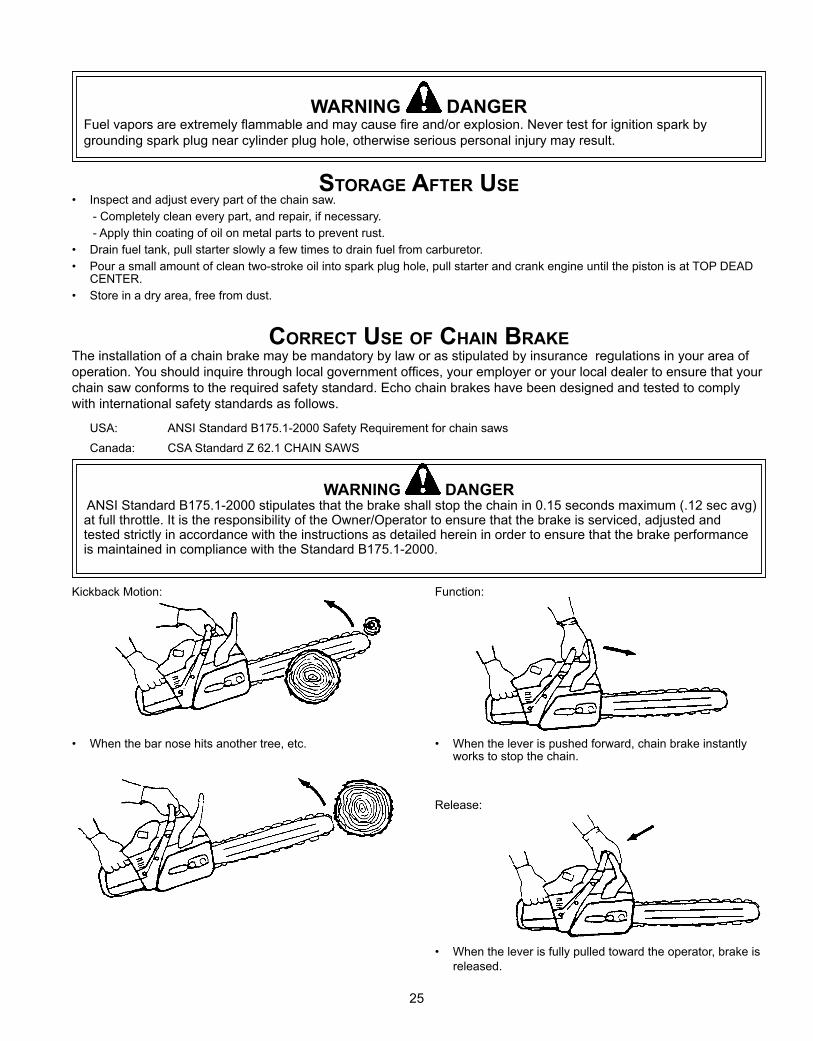
WARNING DANGERFuel vapors are extremely flammable and may cause fire and/or explosion. Never test for ignition spark by grounding spark plug near cylinder plug hole, otherwise serious personal injury may result.
CoRReCt use of Chain bRakeThe installation of a chain brake may be mandatory by law or as stipulated by insurance regulations in your area of operation. You should inquire through local government offices, your employer or your local dealer to ensure that your chain saw conforms to the required safety standard. Echo chain brakes have been designed and tested to comply with international safety standards as follows.
USA: ANSI Standard B175.1-2000 Safety Requirement for chain saws
Canada: CSA Standard Z 62.1 CHAIN SAWS
WARNING DANGER ANSI Standard B175.1-2000 stipulates that the brake shall stop the chain in 0.15 seconds maximum (.12 sec avg) at full throttle. It is the responsibility of the Owner/Operator to ensure that the brake is serviced, adjusted and tested strictly in accordance with the instructions as detailed herein in order to ensure that the brake performance is maintained in compliance with the Standard B175.1-2000.
Kickback Motion:
• When the bar nose hits another tree, etc.
Function:
• When the lever is pushed forward, chain brake instantly works to stop the chain.
Release:
• When the lever is fully pulled toward the operator, brake is released.
26
TESTING THE BRAKE• Start the engine on a solid level surface and run at a fast
idle until warm.• Hold the saw firmly by the handles and accelerate the en-
gine to a fast idle.• Slowly operate the chain brake lever while holding the saw
firmly on the ground. When the brake lever trips, the chain should stop. Immediately release the throttle trigger.
IMPORTANTDo not allow the saw to tip forward in order to avoid damage to the chain.
If the chain does not stop, immediately return the saw to your authorized Echo dealer for repair.
INSTALLATION• Echo recommends that the chain brake should be serviced
by an authorized Echo servicing dealer.
OPERATION• Set the lever in the unlocked position before starting to cut.• If the brake is tripped by kick back reaction, the chain will
stop. Immediately release the throttle to avoid possible damage to the engine or clutch.
• Do not attempt to operate the engine with the brake locked.• When the lever is fully pulled toward the operator, brake is
unlocked.

27
notes
CONSUMER PRODUCTSUPPORT
1-800-673-15588:30 - 4:30 Mon - Fri C.S.T.
ECHO, INCORPORATED400 OakwOOd ROad
Lake ZuRich, iL 60047-1564www.echo-usa.com
seRviCinG infoRmation
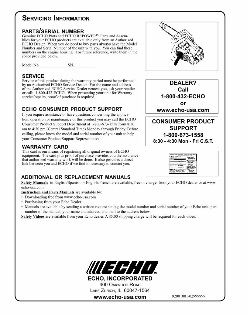
paRts/seRial numbeRGenuine ECHO Parts and ECHO REPOWERTM Parts and Assem-blies for your ECHO products are available only from an Authorized ECHO Dealer. When you do need to buy parts always have the Model NumberandSerialNumberoftheunitwithyou.Youcanfindthesenumbers on the engine housing. For future reference, write them in the space provided below.
Model No. _____________ SN. __________
seRviCeService of this product during the warranty period must be performed by an Authorized ECHO Service Dealer. For the name and address oftheAuthorizedECHOServiceDealernearestyou,askyourretaileror call: 1-800-432-ECHO. When presenting your unit for Warranty service/repairs, proof of purchase is required.
eCho ConsumeR pRoDuCt suppoRtIf you require assistance or have questions concerning the applica-tion, operation or maintenance of this product you may call the ECHO Consumer Product Support Department at 1-800-673-1558 from 8:30 am to 4:30 pm (Central Standard Time) Monday through Friday. Before calling,pleaseknowthemodelandserialnumberofyourunittohelpyour Consumer Product Support Representative.
waRRanty CaRDThis card is our means of registering all original owners of ECHO equipment. The card plus proof of purchase provides you the assurance thatauthorizedwarrantyworkwillbedone.ItalsoprovidesadirectlinkbetweenyouandECHOifwefinditnecessarytocontactyou.
aDDitional oR ReplaCement manuals Safety Manuals in English/Spanish or English/French are available, free of charge, from your ECHO dealer or at www.echo-usa.com.Instruction and Parts Manuals are available by: • Downloadingfreefromwww.echo-usa.com• PurchasingfromyourEchoDealer.• ManualsareavailablebysendingawrittenrequeststatingthemodelnumberandserialnumberofyourEchounit,part
number of the manual, your name and address, and mail to the address below.Safety Videos are available from your Echo dealer. A $5.00 shipping charge will be required for each video.
DEALER?Call
1-800-432-ECHOor
www.echo-usa.com
02001001/02999999