Embed Size (px)
Citation preview

INEEL/EXT-04-00016
Operations and Maintenance Plan for the OU 7-08 Organic Contamination in the VadoseZone Project
August 2004

INEEL/EXT-01-00016Revision 1
Project No. 23256
Operations and Maintenance Plan for the OU 7-08 Organic Contamination
in the Vadose Zone Project
August 2004
Idaho Completion Project Idaho Falls, Idaho 83415
Prepared for the U.S. Department of Energy
Assistant Secretary for Environmental Management Under DOE Idaho Operations Office
Contract DE-AC07-99ID13727

iii
ABSTRACT
A remedy for organic contamination in the vadose zone is being implemented through this operations and maintenance plan in accordance with the Operable Unit 7-08 Record of Decision. The Operable Unit 7-08 Remedial Action Project consists of (1) extracting and destroying organic contaminant vapors present in the vadose zone beneath and within the immediate vicinity of the Radioactive Waste Management Complex and (2) monitoring vadose zone vapors.
The activities and procedures for safe and compliant operation and maintenance of vapor vacuum extraction with treatment units, and the associated monitoring and extraction wells to implement the remedial action, are described in this operations and maintenance plan.

iv

v
CONTENTS
ABSTRACT................................................................................................................................................. iii
ACRONYMS............................................................................................................................................... ix
1. INTRODUCTION.............................................................................................................................. 1
1.1 Purpose .................................................................................................................................. 1
1.2 Scope ..................................................................................................................................... 1
2. DESCRIPTION OF VAPOR VACUUM WITH EXTRACTION OPERATIONS ........................... 2
2.1 System and Equipment Description ...................................................................................... 3
2.1.1 Pretreatment............................................................................................................. 3 2.1.2 Oxidation ................................................................................................................. 3 2.1.3 Exhaust .................................................................................................................... 3
2.2 Catalytic Oxidizer Startup Sequence..................................................................................... 4
2.3 Emergency Shutdown............................................................................................................ 4
2.4 Freeze Protection ................................................................................................................... 5
2.5 Operations Waste................................................................................................................... 5
2.5.1 Waste Management ................................................................................................. 5 2.5.2 Waste Characterization and Management ............................................................... 5 2.5.3 Waste Segregation ................................................................................................... 6 2.5.4 Waste Minimization and Pollution Prevention........................................................ 7
3. DOCUMENTATION ......................................................................................................................... 8
3.1 Prejob Briefings..................................................................................................................... 8
3.2 Material Safety Data Sheets .................................................................................................. 8
3.3 Catalytic Oxidizers ................................................................................................................ 8
3.3.1 Vapor Vacuum Extraction with Treatment Catalytic Oxidizer Startup, Operations, and Shutdown....................................................................................... 8
3.3.2 Vapor Vacuum Extraction with Treatment Unit Operational Sampling ................. 8 3.3.3 System Operability Testing ..................................................................................... 9 3.3.4 Vapor Vacuum Extraction with Treatment Unit D Performance Testing ............... 9 3.3.5 Logbooks ................................................................................................................. 9
4. SYSTEM MAINTENANCE ............................................................................................................ 10
4.1 Preventive Maintenance ...................................................................................................... 10

vi
4.2 Calibration ........................................................................................................................... 10
4.3 Spare Parts ........................................................................................................................... 12
5. VAPOR VACUUM EXTRACTION WITH TREATMENT AIR EMISSIONS MONITORING .. 13
5.1 Air Emissions Regulations .................................................................................................. 13
5.2 Air Dispersion Modeling..................................................................................................... 14
5.3 Occupational Monitoring..................................................................................................... 14
5.3.1 Open Path Fourier Transform Infrared Spectrometry ........................................... 14 5.3.2 Industrial Hygiene Sampling................................................................................. 16
5.4 Vapor Vacuum Extraction with Treatment Performance Monitoring ................................. 18
6. ORGANIC CONTAMINATION IN THE VADOSE ZONE WELL VAPOR MONITORING .... 20
6.1 Organic Contamination in the Vadose Zone Vapor and Extraction Wells.......................... 20
7. ROLES AND RESPONSIBILITIES................................................................................................ 25
7.1 Operable Unit 7-08 Project Personnel ................................................................................. 25
7.1.1 Project Manager .................................................................................................... 25 7.1.2 System or Project Engineer ................................................................................... 25 7.1.3 Operations Field Technician Lead......................................................................... 25 7.1.4 Operations Field Technicians ................................................................................ 27 7.1.5 Planner................................................................................................................... 27 7.1.6 Vadose Zone Sampler............................................................................................ 27 7.1.7 Vadose Zone Fate and Transport Modeler ............................................................ 28
7.2 Environment, Safety, Health, and Quality Assurance Personnel ........................................ 28
7.2.1 Health and Safety Officer ...................................................................................... 28 7.2.2 Safety Professional ................................................................................................ 28 7.2.3 Industrial Hygienist ............................................................................................... 28 7.2.4 Quality Assurance Engineer .................................................................................. 28 7.2.5 Environmental Engineer........................................................................................ 29
7.3 Radiological Control ........................................................................................................... 29
7.3.1 Radiological Engineer ........................................................................................... 29 7.3.2 Radiological Control Technicians ......................................................................... 29
7.4 Maintenance, Construction, and Vendor Support Personnel............................................... 29
7.4.1 Laborers and Heavy Equipment Operators ........................................................... 29 7.4.2 Mechanics and Instrument Technicians ................................................................ 30 7.4.3 Construction Support Personnel ............................................................................ 30 7.4.4 Vapor Vacuum Extraction with Treatment Unit Vendors..................................... 30

vii
7.5 Visitors ................................................................................................................................ 30
8. REFERENCES................................................................................................................................. 31
Appendix A—Unit Drawings ...................................................................................................................A-1
Appendix B—Technical Procedures and Logbook Sheets ....................................................................... B-1
Appendix C—Correspondence ................................................................................................................. C-1
Appendix D—Technician Training Plan and Qualification Checklist......................................................D-1
FIGURES
1. Block diagram of catalytic oxidation system........................................................................................ 4
2. Organic contamination in the vadose zone monitoring wells in the vicinity of the Radioactive Waste Management Complex ............................................................................................................. 21
3. Extraction intervals and vapor port depths in organic contamination in the vadose zone wells with an extraction interval at the Subsurface Disposal Area (Part I) .................................................. 22
4. Extraction intervals and vapor port depths in organic contamination in the vadose zone wells with an extraction interval at the Subsurface Disposal Area (Part II)................................................. 23
5. Vapor port depths in organic contamination in the vadose zone vapor monitoring wells located inside the Subsurface Disposal Area................................................................................................... 24
6. Organization chart of the Operable Unit 7-08 Organic Contamination in the Vadose Zone Project ................................................................................................................................................. 26
TABLES
1. Catalytic oxidizer specifications ........................................................................................................... 4
2. Preventive maintenance activities for catalytic oxidizers ................................................................... 10
3. Calibration intervals for pressure and temperature instruments ......................................................... 11
4. Recommended spare parts .................................................................................................................. 12
5. Applicable or relevant and appropriate requirements and to-be-considered criteria for the organic contamination in the vadose zone remedial action ................................................................ 13
6. Open path fourier transform infrared spectrometry deployment schedule ......................................... 15
7. Maximum detected target compound concentrations and exposure limits ......................................... 16
8. Industrial hygiene sampling results .................................................................................................... 17

viii
ix
ACRONYMS
ARAR applicable or relevant and appropriate requirement
CERCLA Comprehensive Environmental Response, Compensation and Liability Act
DOE U.S. Department of Energy
DRE destruction and removal efficiency
EDF engineering design file
EPA U.S. Environmental Protection Agency
FTIRS fourier transform infrared spectrometer
HASP health and safety plan
HSO health and safety officer
HWD hazardous waste determination
IDAPA Idaho Administrative Procedures Act
IH Industrial Hygiene
INEEL Idaho National Engineering and Environmental Laboratory
ISCST Industrial Source Complex Short Term
MCP management control procedure
O&M operations and maintenance
OCVZ organic contamination in the vadose zone
OSHA Occupational Safety and Health Administration
OU operable unit
PCE tetrachloroethene
PE project engineer
PLC programmable logic controller
PPE personal protective equipment
RCRA Resource Conservation and Recovery Act
ROD record of decision

x
RRWAC reusable property, recyclable materials, and waste acceptance criteria
RWMC Radioactive Waste Management Complex
scfm standard cubic feet per minute
SDA Subsurface Disposal Area
TCA 1,1,1-trichloroethane
TCE trichloroethene
VOC volatile organic compound
VVET vapor vacuum extraction with treatment
WGS Waste Generator Services

1
Operations and Maintenance Plan for the OU 7-08 Organic Contamination
in the Vadose Zone Project 1. INTRODUCTION
1.1 Purpose
The purpose of this plan is to identify the operations and maintenance (O&M) activities for the Operable Unit (OU) 7-08 vapor vacuum extraction with treatment (VVET) units, piping systems, and associated wells. Operable Unit 7-08, organic contamination in the vadose zone (OCVZ), extends from the land surface to the top of the Snake River Plain Aquifer, approximately 177 m (580 ft) beneath the Radioactive Waste Management Complex (RWMC) within the Idaho National Engineering and Environmental Laboratory (INEEL), excluding the Subsurface Disposal Area (SDA) disposal pits and trenches. The vadose zone contains volatile organic compounds (VOCs), primarily in the form of organic vapors, that have migrated from the buried waste in the SDA pits. The OCVZ remedial action is being implemented in accordance with the Record of Decision: Declaration for Organic Contamination in the Vadose Zone Operable Unit 7-08, Idaho National Engineering Laboratory, Radioactive Waste Management Complex, Subsurface Disposal Area (DOE-ID 1994). The primary objective of the OU 7-08 remedial action is to prevent vapor phase contaminants in the vadose zone from reaching the groundwater in concentrations that would result in future concentrations that exceed maximum contaminant levels. As stated in the OU 7-08 Record of Decision (ROD) (DOE-ID 1994), the remedy selected to reduce risks to human health and the environment associated with the organic contaminants present in the vadose zone and to prevent federal and state safe drinking water standards from being exceeded in the future, is VVET. The selected remedy consists of (1) extraction and destruction of organic contaminant vapors present in the vadose zone beneath and within the immediate vicinity of the SDA and (2) monitoring of vadose zone vapors.
1.2 Scope
The activities and procedures for safe and compliant operation and maintenance of VVET units and the associated monitoring and extraction wells to implement the remedial action are described in this O&M plan. Three catalytic oxidation systems are currently deployed at the SDA, designated as Units D, E, and F. All three electrically heated catalytic oxidizers were manufactured by King, Buck Technology located in San Diego, and are capable of processing 300–550 standard cubic feet per minute (scfm) of vapor. Unit D is currently connected to Wells 7V, SE6, IE6, and DE6. Unit F is currently connected to Wells 2E, 7E, SE3, IE3, DE3, IE4, DE4, SE8, IE8, and DE8. Unit E is currently connected to Wells 8901D, DE1, 6E, SE7, IE7, and DE7. Remote- and manually operated valves are used to select and control well-vapor flow from the any of the wells to which the valves are attached.
Regulatory guidelines and reporting requirements for safe and compliant operation of the VVET system are outlined in this plan. Operation of the VVET units complies with applicable U.S. Department of Energy (DOE) orders and federal, state, and local regulations environmental release criteria, monitoring, and reporting requirements.

2
2. DESCRIPTION OF VAPOR VACUUM WITH EXTRACTION OPERATIONS
To implement the selected remedy described in the OU 7-08 ROD, three catalytic oxidation systems are employed at the SDA. The VVET units extract vapor from wells located in the SDA, treat the vapor using catalytic oxidation, and vent the oxidation products through an exhaust stack into the atmosphere. The primary products of oxidation are carbon dioxide (CO2) and hydrochloric acid (HCl).
Operational status of the VVET units includes uptime, planned downtime, and unplanned downtime. Uptime is defined as the period of operation when the VVET units are running and drawing vapor from the extraction well. Planned downtime includes periods of operation when the units are shut down for planned maintenance, planned power outages, or rebound periods. Unplanned downtime includes shutdown of a unit resulting from unplanned power outages, component failure, or operation outside of design parameters. Normal operation will consist of unmanned operation 24 hours a day, 7 days a week. An uptime operational goal will be established for each operational period by the convening agencies, project personnel, and DOE. Operational uptime will be calculated weekly and will be a percentage of uptime out of total available operational time. A review of the operational status of the units will be conducted semiannually and will be reported in the environmental and operational mid-year and end-year data reports.
A primary goal of this O&M plan is to minimize unplanned downtime during the VVET operations phase of the remedial action. This will be accomplished through implementation of a preventive maintenance and instrument calibration schedule. This schedule will serve to detect component deficiencies early and to minimize the failures that result in unplanned shutdown.
A project team has been assembled to draw on the expertise of each engineering discipline (i.e., electrical, mechanical, and chemical). A team of qualified technicians is permanently stationed at the RWMC to start up and shut down the oxidizers, facilitate preventive maintenance activities, and monitor operations. A system engineer is assigned to the OCVZ Project to monitor specific trends of the units (e.g., operating temperature and pressure and system flow rate) and troubleshoot, identify, and locate problems before they cause ultimate failure. Components of this program ensure that operating time for the units is maximized. The semiannual data report provides a forum for discussion of lessons learned during the preceding months of operation. Review and discussion of the lessons learned satisfies required proficiency training to maintain operating technician qualifications.
As stated, planned downtime includes rebound periods conducted at selected sample locations to maximize VOC mass removal. The number and length of the short-term rebound periods will be determined by the project as the VVET operations database is established. The intent of the rebound period is to allow subsurface concentrations to equilibrate so that the progress of the remedial effort can be assessed. If vapor emissions and trends across the short-term rebound periods meet specified statistical criteria, the project will enter into a long-term rebound period referred to as the quiescent compliance verification period (INEEL 2000) to verify that vapor emissions remain within acceptable limits under natural pressure conditions within the vadose zone. If vapor emissions and trends during the compliance verification period meet specified statistical criteria, the project will enter into the long-term monitoring phase. During the long-term monitoring phase, sampling frequencies will be reduced and the VVET units will be taken out of service, based on the understanding that restart of the VVET units is not imminent.
The Health and Safety Plan for Vapor Vacuum Extraction with Treatment for Operable Unit 7-08, Organic Contamination in the Vadose Zone (Miller and Wooley 2003) establishes the procedures and requirements that are used to eliminate or minimize health and safety risks to personnel working at the

3
VVET units and associated monitoring of the vadose zone. The OCVZ Health and Safety Plan (HASP) (Miller and Wooley 2003) specifically contains information about the hazards involved in performing the work as well as actions and equipment that will be used to protect workers while conducting project tasks.
2.1 System and Equipment Description
The treatment process can be divided into the following three basic operations: (1) pretreatment, (2) catalytic oxidation, and (3) stack release of the oxidizer exhaust gas. Functions of each operation are discussed in the sections below. Piping and instrumentation diagrams of the VVET Units D, E, and F catalytic oxidizer are included in Appendix A. Additional Unit D, E, and F system documentation can be located in the Unit D, E, and F system design description documents (SDD-174, SDD-175). Detailed component-level information, including system design criteria, is recorded in the INEEL Configuration Management System Component Equipment List.
2.1.1 Pretreatment
The pretreatment equipment collects extracted VOC vapor into a header using a vacuum blower. The VOC vapor is withdrawn from the wellheads and carried to the oxidizers through insulated piping. Supplemental heat is provided to the flowing vapor to minimize condensation of vapor in the transfer lines by heaters in the well line. Each manifold is configured to accept feed from multiple well locations. The fraction of feed withdrawn from any given well is controlled through the adjustment of hand control valves or automatic flow-control valves on the respective well lines. Each well line is equipped with a drain at the lowest point to remove any accumulated liquids in the well line. Vapor flow rate is measured from each extraction well upstream of the manifold connection. Total vapor pressure, temperature, and flow are monitored and controlled in the main vapor header upstream of the oxidizer.
2.1.2 Oxidation
Catalytic oxidation is used in contaminant destruction in VVET Units D, E, and F. Vapor flow entering the catalytic oxidizer is directed through a vapor liquid separator to remove any free-phase liquids that may be entrained in the vapor flow. The flow is then directed into the heat exchanger where heat is recovered from exhaust gases into the inlet flow. Exiting the heat exchanger, the inlet flow is conducted past an electric bayonet-style heater where the temperature is elevated to the set point temperature of the catalytic process, nominally 950°F. At this temperature, halogenated compounds are destroyed in a catalytic reaction. Before exiting, the vapor passes through a heat exchanger to recover heat from the outlet stream.
2.1.3 Exhaust
Oxidation products are exhausted from the system through a 9.1-m (30-ft) stack. The carbon tetrachloride (CCl4) destruction and removal efficiencies (DREs) for the catalytic oxidation systems are calculated to be 99.99% (Soelberg et al. 2001). While composed primarily of excess air, water, and oxidation products, trace quantities of unreacted VOCs (e.g., CCl4, trichloroethene [TCE], tetrachloroethene [PCE], and 1,1,1-trichloroethane [TCA]) are expelled from the stack with the product gases. The primary oxidation products are HCl and CO2, with a lesser quantity of chlorine gas (Cl2). The presence of excess water works to minimize the production of Cl2. The stack temperature for the catalytic system is approximately 350–500°F.

4
2.2 Catalytic Oxidizer Startup Sequence Catalytic oxidation system startup begins with an inspection to verify valve positions and resolve
any conditions that may have resulted in a prior shutdown. After inspection, the blower is started, feeding ambient air into the oxidation system. The system heater is enabled and temperature is raised to the startup temperature of 850°F. With the catalyst at the startup temperature, the extraction well valve is opened and vapor oxidation commences. Figure 1 illustrates the major equipment associated with the catalytic oxidation system. Table 1 shows catalytic oxidizer specifications.
2.3 Emergency Shutdown Each of the oxidation systems is equipped with a programmable logic controller (PLC), which
will automatically shut the unit off in the event of an unexpected or potentially unsafe condition. Alarm conditions are indicated on the supervisory control and data acquisition screens, operator interface terminal (Unit D OIT), and touch screen interface (Unit E/F).
VOC Process Vapor
Fresh Air
Quench Dilution
Air
Vapor / Liquid
Separator
Vacuum / Compressor Unit (VCU) Heat
Exchanger
Preheater
Catalytic Reactor
Stack
Effluent to Atmosphere
HD CatOx Insulated Enclosure
Operational Sampling
Figure 1. Block diagram of catalytic oxidation system.
Table 1. Catalytic oxidizer specifications. Specificationsa Unit D Units E and F
Nominal capacity 500 scfm 500 scfm Daily destruction rate of Cl-VOCb
415.2 lb/day (maximum) 415.2 lb/day (maximum)
Equivalent concentration 1,500 ppmv mixed Cl-VOC 1,500 ppmv mixed Cl-VOC Dimensions 10-ft 10-in. long × 8-ft 6-in. wide 30-ft long × 10-ft wide Weight 6,100 lb (approximate) 24,000 lb (approximate)c Electric requirements:
Vacuum compressor unit motor
25 hp, 460 V, 3Ø 75 hp, 460 V, 3Ø
Preheater 62 kW, 460 V, 3Ø 70 kW, 460 V, 3Ø Heat exchanger efficiency 60% thermally efficient 60% thermally efficient
a. As provided by King, Buck Technology. b. Calculated by King, Buck from procurement specification of DRE based on operating temperature and gas flow rate. c. Eight of Units E and F include the weight of the cargo container because the system is built into the enclosure. DRE = destruction and removal efficiency VOC = volatile organic compound

5
2.4 Freeze Protection
Freeze protection is afforded to each of the oxidizers by using steel enclosures. Temperature-sensitive components are housed within the heated structures to minimize exposure to cold temperatures. In a similar manner, electronics, including the PLCs, are housed within climate-controlled enclosures. Flex lines are installed on each pipe run to minimize the stress caused by frost heave. Multiple heaters have been placed in long stretches of well line to prevent ice damming.
2.5 Operations Waste
Generation of waste materials requiring hazardous material handling and disposal is not anticipated. A waste disposition and disposal form has been developed through Waste Generator Services (WGS) to handle any liquid hazardous waste (e.g., vapor condensate) that may accumulate during system operation. Other waste streams, including various system filters, belts, and oils, are dispositioned and disposed of through WGS as necessary. All materials are surveyed by radiological control technicians (before removal from the SDA) to verify that no radioactive contamination is present.
2.5.1 Waste Management
The waste streams that result from OCVZ operations are appropriately managed as Comprehensive Environmental Response, Compensation and Liability Act (CERCLA) (42 USC § 9601 et seq., 1980) waste generated in support of implementing the OU 7-08 ROD. This section describes the waste streams to be generated and the considerations associated with generation, storage, and disposition of the waste streams including waste minimization considerations. As indicated below, the nature of the VVET operations results in only limited waste generation primarily consisting of solid industrial waste.
All waste streams generated from OCVZ operations will be managed under the direction of OCVZ Project personnel in close coordination with the WGS organization in accordance with the applicable or relevant and appropriate requirements (ARARs) documented in the OU 7-08 ROD and the requirements and processes defined in the applicable INEEL management control procedures (MCPs). In particular, INEEL Companywide Manual 17 - Waste Management will be followed in addition to other applicable internal documents such as the INEEL Reusable Property, Recyclable Materials and Waste Acceptance Criteria (RRWAC) (DOE-ID 2004). As required by the ROD and internal procedures, completion of a hazardous waste determination (HWD) is key to the initial management of all waste streams.
2.5.2 Waste Characterization and Management
Operation and maintenance of the various OCVZ systems results in the generation of a limited number of waste streams. The primary materials generated are solid waste items classified as industrial or conditional industrial waste under the RRWAC. Examples of these waste streams include tedlar bags and air filters.
It is noted that the SDA itself does contain waste streams that may potentially be associated with Resource Conservation and Recovery Act (RCRA) (42 USC § 6901 et seq., 1976) listed hazardous waste numbers; however, the uncontained gases (i.e., vadose zone vapors) processed by the VVET units are not solid waste by definition and, therefore, are not associated with listed waste codes.
In the event that equipment leaks or chemical spills occur, the spilled materials (along with visibly contaminated soil) will be containerized, subjected to a complete HWD, and dispositioned as waste in accordance with INEEL procedures. Generally, routine spills will be cleaned up at the time they occur, but no longer than 24 hours after the spill, as allowed by normal operational conditions (i.e., absent

6
emergency conditions). All spills, regardless of amount, require notification of the spill notification team in accordance with applicable MCPs.
The waste resulting from these operations may require interim storage before transfer for disposal. Because there is a small potential that some waste streams will be associated with RCRA management considerations, the waste may be stored in containers pending return of analytical data and completion of the HWD. A waste storage area for managing CERCLA waste has been established by WGS personnel to ensure appropriate management of residual materials pending completion of the HWD and shipment for disposal.
Packaging will be in compliance with the RRWAC, RCRA regulations found in 40 CFR 264 Subpart I, and U.S. Department of Transportation regulations (49 CFR 171, 173, 177, and 178). The assigned WGS personnel, along with Packaging and Transportation organizations, should be consulted before waste generation to identify specific container types to be used for the anticipated waste. Appropriate containers for waste include 208-L (55-gal) drums and other suitable containers that meet the Department of Transportation regulations on packaging (49 CFR 171, 173, 178, and 179). All waste containers will be labeled appropriately.
Records and reports related to waste management are required to be maintained as indicated by MCP-3475, “Temporary Storage of CERCLA-Generated Waste at the INEEL.” Some of these may be completed by others, but must be available either at the RWMC or with the OCVZ or Waste Area Group 7 project files located in the Technical Support Building in Idaho Falls. These records shall include, but not be limited to, the following:
• Hazardous waste determinations, characterization information and statements of process knowledge
• CERCLA Storage Area inspection reports and log-in and log-out history
• Training records
• Documentation with respect to all spills.
2.5.3 Waste Segregation
Construction waste streams will generally not be hazardous waste, but rather will be industrial waste and will not typically require RCRA or Toxic Substances Control Act compliant storage (15 USC § 2601 et seq., 1976). Some industrial waste generated during construction (e.g., office waste and lunch trash) can be disposed of in cold waste receptacles.
Container storage areas and containers for collection of waste will be labeled clearly to identify waste type. Waste will generally be segregated according to waste category (e.g., hazardous classification) and type (i.e., solid, liquid, soil, and sludge). This segregation entails separation of mixed waste, low-level waste, and hazardous, solid, and liquid waste streams within containers and within the storage facility. Waste segregation may be an iterative process such that initial classifications of waste may change after receipt of analytical results. Finally, segregation of waste materials to address issues related to incompatible chemicals or properties (e.g., flammability) will also occur.

7
2.5.4 Waste Minimization and Pollution Prevention
The OU 7-08 O&M activities are conducted in accordance with the U.S. Department of Energy, Idaho Operations Office Idaho National Engineering and Environmental Laboratory Pollution Prevention Plan (DOE-ID 2000). The plan specifies pollution prevention and waste minimization program activities and methods that will be employed to reduce the quantity and toxicity of waste generated at the INEEL. Various general pollution prevention program information relating to waste minimization (e.g., waste tracking and employee incentive programs) can be referenced in the plan.
The following project-specific activities will ensure that minimal quantities of waste are generated, or that hazardous waste generation is avoided:
• Personal protective equipment (PPE) use will be minimized by reusing and laundering items to the extent possible
• Controls on disposal and materials accepted for use will be implemented (as appropriate) to ensure minimal waste generation
• Equipment maintenance is required to prevent undesirable conditions (e.g., leaking hoses and fittings)
• Industrial waste disposition will be minimized by discussing conservation measures with operational staff during daily briefings
• Any potential hazardous waste will be systematically segregated from industrial or sanitary waste streams
• All samples necessary will be collected at one time so that additional waste is not generated from resampling.
The INEEL project managers assigned to each remediation project have specific responsibility for implementing waste minimization requirements for that project. The waste minimization and pollution prevention requirements, as implemented in MCPs, are required reading for all project managers. Project personnel are required to read and understand the pertinent portions of project plans relating to waste minimization and pollution prevention (e.g., health and safety plans and test plans), with respect to their functions, before performing the tasks.
With certification of the Integrated Safety Management System, pollution prevention becomes an integral part of planning, operations, and work activities at all INEEL facilities. Pollution prevention goals and training programs have been implemented into Integrated Safety Management System documentation, including various INEEL program description and requirements documents and MCPs.

8
3. DOCUMENTATION
Procedures and operator logbooks have been developed to direct and record operating data and events. Operating data include startup, shutdown, normal operation, troubleshooting, and operability testing. The following section identifies and describes various procedures applicable to operation and testing of the oxidation systems. Appendix B provides copies of the log sheets and Technical Procedures (TPRs) –1662, “VVET Catalytic Oxidizer Startup, Operations, and Shutdown,” and –1634, “VVET Units E and F Catalytic Oxidizer Startup, Operation, and Shutdown”
Drawings are updated and maintained in accordance with MCP-2377, “Development, Assessment, and Maintenance of Drawings.” The drawings are available within the INEEL Electronic Data Management System. System drawings, including piping and instrumentation diagrams, are included in Appendix A.
3.1 Prejob Briefings
Prejob briefings are conducted in accordance with MCP-3003, “Performing Pre-Job Briefings and Post-Job Reviews,” and documented on Form 434.14, “Pre-Job Briefing Checklist.” Individual prejob briefings are conducted and documented before maintenance activities, system repairs, modifications, and execution of new or revised procedures. Executed prejob briefing forms are maintained as work control documentation with the associated Standard (STD) –101, “Integrated Work Control Process,” work package or project file.
3.2 Material Safety Data Sheets
Material safety data sheets for any chemicals used on the project can be accessed through the INEEL intranet. A list of chemicals used or stored at the job site is available through the INEEL Chemical Management System.
3.3 Catalytic Oxidizers
3.3.1 Vapor Vacuum Extraction with Treatment Catalytic Oxidizer Startup, Operations, and Shutdown
Procedures in TPRs-1662 and -1634 provide specific instructions for startup, operation, and shutdown of the catalytic units; direct the pre-startup inspection; and specify flow, pressure, and temperature parameters appropriate for system operation. Operational activities are performed by a qualified VVET technician.
3.3.2 Vapor Vacuum Extraction with Treatment Unit Operational Sampling
Procedures in TPRs -1662 and -1634 direct the routine operational sampling of the influent vapor and air mixture from the inlet to the VVET catalytic oxidizers. These procedures cover daily collection of samples, transportation of the samples to the Central Facilities Area laboratory, and notation of sampling actions in the VVET unit narrative log. Samples are collected daily (i.e., Monday through Thursday) and analyzed using a Bruel & Kjar multigas photoacoustic analyzer.

9
3.3.3 System Operability Testing
Preshipment component checkout and system operability testing was performed at the manufacturer’s shop to ensure that individual components of each oxidizer functioned as designed and according to the project technical specification before shipment to the INEEL. Testing was witnessed and approved by INEEL representatives. Test reports were submitted to INEEL, and were reviewed and approved as part of the catalytic oxidizer procurement subcontract vendor data submittals provided by King, Buck Technology.
Additional component checkout and operability testing was completed at the INEEL after delivery and installation of the catalytic oxidizers and associated piping systems. This testing demonstrated that oxidizers were not damaged during shipping, and that field instruments and components, including the transformer, heaters, valves, and thermocouples, were properly installed. Proper function of the Supervisory Control and Data Acquisition system was also verified during onsite system operability testing. Component checkout and system operability test reports were submitted to INEEL, and were reviewed and approved as part of the catalytic oxidizer installation subcontract vendor data submittals provided by L&L Mechanical and Wheeler Electric subcontractors. Following onsite system operability testing and final turnover from construction to operations, each of the catalytic oxidation systems entered a 6-week period of shake-down operations before full-scale operation began.
3.3.4 Vapor Vacuum Extraction with Treatment Unit D Performance Testing
A catalytic oxidizer performance test (i.e., acceptance test ) was conducted for the VVET Unit D catalytic oxidizer according to the test plan (Soelberg 2000). The test provided data for the following emissions modeling test objectives:
• Determine the CCl4 destruction and removal efficiency
• Determine emissions of HCl and Cl2 resulting from operation of Unit D
• Determine any measurable amounts of VOC products of incomplete destruction.
The performance test results demonstrated that CCl4 destruction and removal efficiency ranged between 99.997 and 99.999%. The results were calculated from the gravimetric flow rate of feed CCl4, and CCl4 emissions measured by the U.S. Environmental Protection Agency (EPA) Method 0031 (Soelberg 2000).
Because VVET Units E and F were of similar construction to Unit D, performance testing was not required as part of final acceptance.
3.3.5 Logbooks
The VVET operations logbooks are used to record system operating data for flow, temperature, and pressure, and to guide the technician in completion of routine surveillance tasks to monitor equipment conditions. As the logbooks are completed, the technician ensures that all systems are functioning properly. Circumstances and reasons for any operational downtime, as well as their duration, are recorded in the logbooks. Operations logbooks are kept either at the VVET units or in the site project office. Completed logbooks are retained in document control and are scanned into the Optical Imaging System, providing access to archived operations data. Logbook sheets are included in Appendix B.

10
4. SYSTEM MAINTENANCE Maintenance instructions and procedures, along with a thorough check of all operating conditions,
have been developed and implemented to ensure the proper operation of the catalytic oxidizers. A scheduled maintenance program has been developed to minimize operational problems (e.g., equipment failure). Various maintenance activities, including instrument calibration, are completed at various monthly, quarterly, semiannual, and annual intervals, as recommended by manufacturer specifications.
4.1 Preventive Maintenance
Preventive maintenance activities are completed to maximize operational uptime of the oxidation systems. Maintenance activities are detailed in Table 2 with their respective intervals.
Details of past system failures and measures taken to correct them are collected and reported at 6-month intervals as part of the OCVZ semiannual data report. This information is collected in the system optimization and maintenance section of the data report. Information in this section of the report includes the details of any process enhancements, system repairs, changes to the preventive maintenance procedures, and any planned future modifications intended to increase process performance. This information is used to identify required changes to the preventive maintenance schedule to ensure continued operational reliability.
4.2 Calibration
Instrument calibrations are completed at regular intervals to maximize the quality of operations data and the confidence with which these data can be applied to make judgments relative to process performance. Calibration of only the primary flow element in each system is required. The flow elements are calibrated according to the intervals in Table 3. The primary flow elements will undergo an annual performance check that will use a calibrated hotwire anemometer for in situ flow verification. Concurrence of the INEEL calibration lab with the OCVZ calibration approach is documented in correspondence included in Appendix C. Calibration of other process indicators, including wellhead flowmeters, temperature elements, and pressure transmitters, is not required.
Table 2. Preventive maintenance activities for catalytic oxidizers.
VET Unita Equipment Tag Description Activity Interval
VVED VVEE VVEF
BLO-101 Blower Grease blower bearings as necessary, check for unusual vibration.
Monthly
VVED VVEE VVEF
BLO-101 Blower Drain, flush, and replace gearbox oil. Use only straight mineral oil (aviation oil).
Quarterly
VVED VVEE VVEF
BLO-101 Blower Check tightness of pulley; inspect drive belts.
Quarterly
VVED VVEE VVEF
FLT-102 Ambient air intake filter
Inspect and brush off collected dust and debris or replace as necessary.
Quarterly

Table 2. (continued).
11
VET Unita Equipment Tag Description Activity Interval
VVED VVEE VVEF
FLT-101 Demister pad Inspect and brush off collected dust and debris or replace as necessary.
Semiannual
VVED AC-605 Air conditioning filter
Inspect and brush off collected dust and debris or replace as necessary.
Monthly
VVED VVEE MO-101 Blower motor Grease motor bearings as necessary.
Annual
VVEE VVEF UIT-101 Pressure transmitter
Complete performance check.
Annual
VVED Immersion heaters Check tightness and clean line connections as necessary.
Annual
VVEE HTR-140, -150, -160, -201
Immersion heaters Check tightness and clean line connections as necessary.
Annual
VVEF HTR-140, -150, -160, -170, -172, -201
Immersion heaters Check tightness and clean line connections as necessary.
Annual
VVED VVEE VVEF
VLS-101 Vapor liquid separator
Remove and clean view ports.
Annual
VVED VVEE VVEF
HE-300 Heat exchanger Open ports. Inspect for moisture buildup.
Annual
a. VVED, VVEE, and VVEF are designators for VVET Units D, E, and F, respectively, in accordance with the INEEL configuration management database.
Table 3. Calibration intervals for pressure and temperature instruments.
Instrument Tag Number
Instrument Description Manufacturer
Instrument Calibration
Range
Recommended Calibration
Interval
VVED-PDT-101 Differential pressure transmitter
Rosemount 0–10 in. H2O
Annual
VVED-FE-101 Differential pressure process flow sensor
Dwyer Instruments
0–500 scfm Annual
VVEE-UIT-101 Multivariable transmitter Rosemount 0–500 scfm Annual
VVEF-UIT-101 Multivariable transmitter Rosemount 0–500 scfm Annual

12
4.3 Spare Parts
Spare parts are ordered and maintained in storage at the RWMC. Table 4 lists spare parts for the catalytic oxidizer. The master equipment list, including part descriptions, is available as a vendor data submittal from King, Buck as a separate document.
Table 4. Recommended spare parts.
VVET Unita Item No. Manufacturer Part No. Description
VVED FLT-101 Solberg 235P Filter replacement (McMaster-Carr)
VVED FLT-102 ACS 5CA 10 in. O.D. × 6 in. 304LSS demister pad
VVED BLO-101 Gates/Grainger BX90 Belts for blower
VVEE FLT-101 Solberg 235P Filter replacement (McMaster-Carr)
VVEE FLT-102 ACS 5CA 10 in. O.D. × 6 in. 304LSS demister pad
VVEE BLO-101 Gates/Grainger BX90 Belts for blower
VVEF FLT-101 Solberg 235P Filter Replacement (McMaster-Carr)
VVEF FLT-102 ACS 5CA 10 in. O.D. × 6 in. 304LSS demister pad
VVEF BLO-101 Gates/Grainger BX90 Belts for blower
VVED, E, and F VLS Grainger 1U928 View port
VVED, E, and F QC101 Swagelok SS-QC4-B-4PM
Quick-disconnect sample ports
a. VVED, VVEE, and VVEF are designators for VVET Units D, E, and F, respectively, in accordance with the INEEL configuration management database.

13
5. VAPOR VACUUM EXTRACTION WITH TREATMENT AIR EMISSIONS MONITORING
The VOCs expected in the influent vapor stream for each type of unit are chloroform (CHCl3), TCE, TCA, PCE, and CCl4. Air dispersion modeling has been performed to estimate the expected discharge of each compound and to determine the resulting health effects to collocated workers and persons at the nearest receptor site. Air dispersion modeling is discussed in the following section.
Two sampling methods were used to monitor worker exposure to hazardous chemicals. Included in these were open path fourier transform infrared spectrometer (FTIRS) and active sampling area monitoring. Occupational monitoring was conducted at various locations in the SDA, as described in the sections below.
Influent and effluent vapor sampling and analysis is also performed to measure performance of the catalyst at Units D, E, and F. Performance testing is completed using FTIRS. Performance monitoring is discussed below.
5.1 Air Emissions Regulations As a CERCLA project, the detailed regulatory framework under which the remedial action is taken
is defined by the ARARs set in the ROD. These represent the substantive requirements that are to be met by the OCVZ Remedial Action Project. The ARARs and other requirements to be considered, as set by the ROD for the OCVZ remedial action, are presented in Table 5.
Table 5. Applicable or relevant and appropriate requirements and to-be-considered criteria for the organic contamination in the vadose zone remedial action.
Statute Regulation Relationship RCRA IDAPA § 58.01.05.500.05, (40 CFR 261.10, 261.20–
261.24) “Idaho Rules, Regulations and Standards for Hazardous Waste.”
Relevant and appropriate
40 CFR 264.600 Subpart X, “Miscellaneous Units.” Relevant and appropriate
Clean Air Act 40 CFR 61.92, “National Emission Standards for Radionuclide Emission from DOE Facilities.”
Applicable
IDAPA § 58.01.01.577, “Ambient Air Quality Standards for Specific Air Pollutants.”
Applicable
Idaho Toxic Air Pollutants Non-Carcinogenic Increments
IDAPA § 58.01.01.585, “Idaho Toxic Air Pollutants Non-Carcinogenic Increments.”
Applicable
Idaho Toxic Air Pollutants Carcinogenic Increments
IDAPA § 58.01.01.586, “Idaho Toxic Air Pollutants Carcinogenic Increments.”
Applicable
Idaho Rules for Control of Fugitive Dust
IDAPA § 58.01.01.651, “Idaho Rules for Control of Fugitive Dust.”
Applicable
Idaho Demonstration of Preconstruction Compliance with Toxic Standards
IDAPA § 58.01.01.210.10, “Idaho Demonstration of Preconstruction Compliance with Toxic Standards.”
Relevant and appropriate
DOE order DOE Order 5820.2A, “Radioactive Waste Management.” To be considered material
DOE = U.S. Department of Energy RCRA = Resource Conservation and Resource Act

14
5.2 Air Dispersion Modeling
Engineering Design File (EDF) –1901, “Operable Unit 7-08 Air Dispersion Modeling and Health Effects from Thermal and Catalytic Oxidation Unit Emissions at the Radioactive Waste Management Complex,” provides information on dispersion of seven nonradioactive contaminants (i.e., CHCl3, TCE, TCA, PCE, CCl4, HCl, and Cl2) generated from two thermal oxidation units (i.e., VVET Units A and B) and one catalytic oxidation unit (i.e., Unit D) at the RWMC using the Industrial Source Complex Short Term 3 (ISCST3) model (EPA 1995). The ISCST3 air model (EPA 1995) was used to evaluate the maximum 1-hour, 8-hour, and 24-hour concentrations at the RWMC in a 50-m grid of receptor sites, as well as the maximum annual concentrations at offsite public access locations, US Highway 20/26, the Experimental Breed Reactor-1 access road and visitor center. Results are compared with occupational exposure values promulgated by the American Conference of Government Industrial Hygienists (ACGIH 2000), the Occupational Safety and Health Administration (OSHA), and the National Institute for Occupational Safety and Health (NIOSH) with State of Idaho ambient air standards (IDAPA 58.01.01.577, Section 006), and with EPA health protective limits. Modeling results indicate that estimated air concentrations will not exceed regulatory limits and standards on and off the RWMC.
The oxidizer units have been installed to minimize the additive effects at any receptor location. To achieve this, care was taken to ensure that no two units were placed directly in line in the prevailing wind direction. This minimized the likelihood of exceeding any OSHA, State of Idaho, or EPA air quality limits. Dispersion modeling completed and documented in EDF-1901 indicates that the emissions from oxidizers Units A, B, and D were unlikely to exceed any regulatory limits.
The oxidizer units have been installed to minimize the additive effect at any receptor location. To achieve this, care was taken to ensure that no two units were placed directly in line in the prevailing wind direction. This minimized the likelihood of exceeding any OSHA, State of Idaho, or EPA air quality limits or the maximum ground level concentrations regulatory limits. Dispersion modeling completed and documented in EDF-1901 indicated that the emissions from oxidizers VVET Units D, E, and F were unlikely to result in exceeding any regulatory limits.
5.3 Occupational Monitoring
Two methods were used to monitor worker exposure to hazardous chemicals. Included in these were open path FTIRS and active sampling area monitoring. Monitoring was conducted at various locations in the SDA as described in the following sections.
5.3.1 Open Path Fourier Transform Infrared Spectrometry
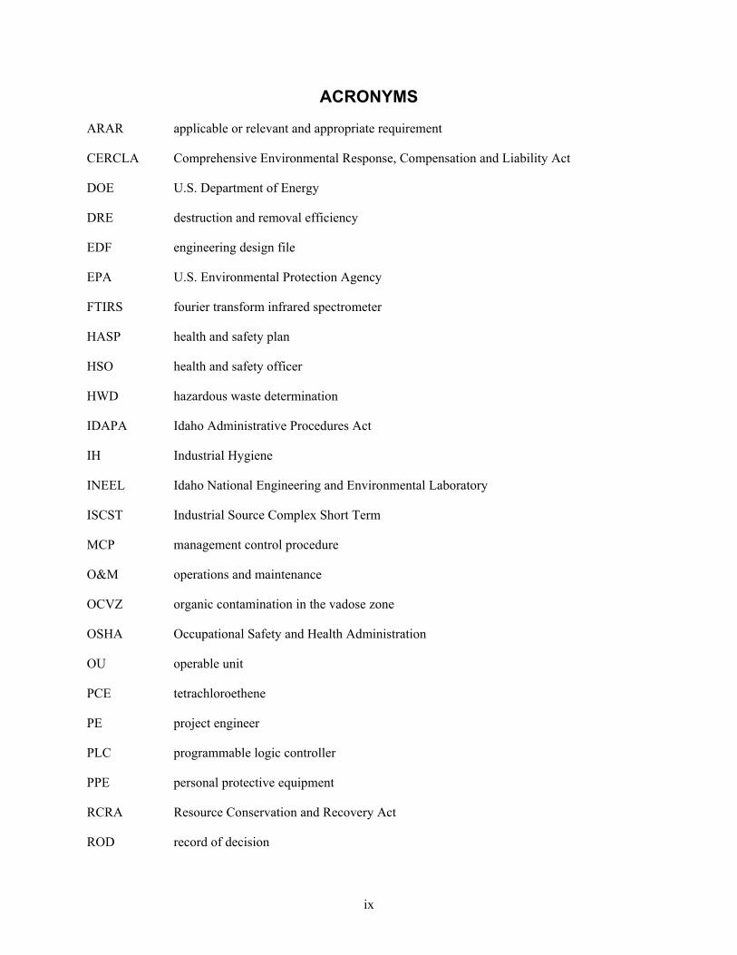
Air monitoring using open path FTIRS was completed during 1999, 2000, and 2001 to determine the impact on air quality from operating the three VVET units located in the SDA. Two open path FTIRSs were deployed during the 1999, 2000, and 2001 field seasons at three locations in the prevailing downwind direction of the VVET units. The two open path units were rotated through the three sampling locations at prescribed intervals as shown in Table 6. It is important to note that the open path FTIRSs were calibrated by the manufacturer, but outside of an ANSI Z540-1, “American National Standard for Calibration—Calibration Laboratories and Measuring and Test Equipment General Requirements,” certified calibration program. Monitoring results and analysis of data collected using the open path FTIRS are reported in the Air Monitoring Results of the Subsurface Disposal Area at the Radioactive Waste Management Complex for Operable Unit 7-08 Organic Contamination in the Vadose Zone 2001 Supplement (Harvego 2002). Additional monitoring is planned to support future project and regulatory decisions involving emissions.
15
Table 6. Open path fourier transform infrared spectrometry deployment schedule.
Open Path Fourier Transform Infrared
Unit Dates Monitoring Location Path Length
Unit 1 6/21/00 to 7/27/00 Unit C 195 m
Unit 2 5/10/00 to 8/21/00 Unit A 210 m
Unit 2 8/21/00 to 10/31/00 Unit B 180 m
Unit 1 8/21/01 to 9/29/01 Unit A 190 m
Unit 1 9/29/01 to 11/1/01 Unit B 180 m
Unit 2 8/21/01 to 11/1/01 Unit D (replaced Unit C in 2001)
200 m
This air monitoring results report provides the measured concentrations of 10 target off-gas compounds, eight VOCs, and two volatile inorganic compounds (i.e., HCL andCO2). Target compounds are listed below:
• 1,1,1-Trichloroethane
• Carbon monoxide
• Carbon tetrachloride
• Chloroform
• Freon 113
• Hydrochloric acid
• Methane
• Methylene chloride
• Propane
• Trichloroethene.
This air monitoring results report also provides a summary of monitoring activities completed during the 2000 and 2001 field seasons including deployment schedule, generalized monitoring procedures, and data analysis. The report also provides interpretation of trends in the data, draws conclusions, and makes recommendations for future air monitoring.
A comparison of detected instantaneous compound concentrations to Industrial Hygiene (IH) exposure limits showed that in all cases, contaminant concentrations were well below any 8-hour time-weighted average exposure limit. The observed maximum target compound concentrations and the associated exposure limits are detailed in Table 7.

16
Table 7. Maximum detected target compound concentrations and exposure limits.
Target Compound 8-Hour Exposure Limit Maximum Instantaneous
Concentrationa
1,1,1-Trichloroethane 350 ppmvb,c 0.29 ppmv
Carbon monoxide 25 ppmvb 0.33 ppmv
Carbon tetrachloride 5 ppmvb 0.13 ppmv
Chloroform 10 ppmvb 0.24 ppmv
Freon 113 1,000 ppmvb,c 0.16 ppmv
Hydrogen chloride 5 ppmvd 0.10 ppmv
Methane N/Ae 0.44 ppmv
Methylene chloride 25 ppmvc 0.59 ppmv
Propane 1,000 ppmvc 0.10 ppmv
Trichloroethene 50 ppmvb 0.20 ppmv a. Data were collected with instruments not calibrated under a program conforming to ANSI Z540-1. These data should be considered survey quality and preliminary in nature. b. The value shown was obtained from ACGIH (2001). c. The value shown was obtained from the Occupational Safety and Health Standards for General Industry (29 CFR 1910). d. The value shown represents the ceiling limit for this compound. e. N/A = not applicable.
5.3.2 Industrial Hygiene Sampling
Industrial Hygiene sampling took place in the OCVZ VVET Unit A and B enclosures on August 28, 2001, and August 29, 2001, respectively. The Unit D enclosure was not sampled because it was out of service at the time. All samples were taken using active sampling pumps and covered a full-day sample period. Airborne contaminants sampled using National Institute for Occupational Safety and Health (NIOSH) analysis methods included chlorine gas (NIOSH Method 6011), HCl (NIOSH Method 7903), TCE (NIOSH Method 1003), CHCl3 (NIOSH Method 1003), and CCl4 (NIOSH Method 1003). The doors on the Unit A enclosure were both closed during the initial part of the sampling in an effort to create a worst-case scenario environment. By noon, the temperature had risen considerably inside the unit enclosure, and one door was propped open. Samples in the Unit B enclosure were taken with one door open and one door closed for the entire sample period. Schneider Laboratories performed the analyses. The normal operating configuration for each of the enclosures is with the skirting on and the personnel access doors closed; however, personnel access doors are often left open during the summer months to allow air to circulate through and cool the enclosures. From an IH standpoint, the enclosures with closed doors present a worst-case scenario.
Industrial Hygiene area sampling was conducted in the OCVZ VVET Unit A and D enclosures on February 11, 2002. Airborne contaminants sampled again included chlorine gas, HCl, TCE, CHCl3, and CCl4. As before, sampling was performed using NIOSH analytical method numbers 6011 and 7903, for chlorine gas and HCl, respectively. The organic samples were taken using SKC 575-series passive samplers for organic vapors. Chlorine gas and HCl were sampled over 385 minutes. The organic series was sampled over 23 hours (1,380 minutes). The doors were closed on both enclosures during the entire sampling period. Table 8 provides the sampling results.

17
Table 8. Industrial hygiene sampling results.
Analyte Actual Exposure
(ppmv) Report Limit
(ppmv) Unit A August 28, 2001
Chlorine <0.004 0.005 Hydrochloric acid <0.008 0.005 Tetrachloroethene <0.015 0.041 Chloroform <0.020 0.040 Carbon tetrachloride 0.050 0.040
Unit B August 29, 2001 Chlorine <0.004 0.005 Hydrochloric acid <0.009 0.005 Tetrachloroethene <0.014 0.041 Chloroform <0.019 0.040 Carbon tetrachloride <0.015 0.040
Unit D February 11, 2002 Chlorine <0.005 0.5, C1a
Hydrochloric acid <0.05 C5 Trichloroethene <0.50 50 Chloroform <0.58 10 Methylene chloride <0.85 25 Carbon tetrachloride <0.45 5
Unit A February 11, 2002 Chlorine <0.005 0.5, C1 a Hydrochloric acid <0.05 C5 a Trichloroethene <0.50 50 Chloroform 0.91 10 Methylene chloride <0.85 25 Carbon tetrachloride 3.20 5
a. Most conservative limit is listed. Ceiling values are denoted by “C”.
Two analytes (i.e., CHCl3 and CCl4) were found above the respective limits of detection, both in the Unit A enclosure sample. The CHCl3 detection was very low and does not pose a health concern to the OCVZ VVET employees. The CCl4 results showed a 23-hourr average of 3.20 ppmv in the second set of samples. Because this is a full 23-hour average air sample, it is not indicative of actual employee exposure.
In initial industrial hygiene sampling (August 28, 2001), the highest CCl4 concentration was 0.05 ppmv, 1/64 the concentration of the latest sample, 3.2 ppmv (February 11, 2002). The initial sample was collected with one Unit A door propped open and with no skirting installed. The latest sample was collected with the doors closed and the skirting installed. This may explain the variation in sample results.

18
Future IH sampling and monitoring will focus on the CCl4 concentrations inside Unit A to verify the results of the past two samplings.
Industrial Hygiene sampling is performed on a periodic basis. Sampling at Units E and F will be conducted during 2004. Collocated worker monitoring occurs at least once per year, or more often as deemed necessary. The monitoring station is mobile and has traditionally been deployed near the units where the highest contaminate concentrations would likely occur. The monitoring station, however, can be moved to any location on the 50-m (55-yd) grid modeled in EDF-1901.
5.4 Vapor Vacuum Extraction with Treatment Performance Monitoring
Influent and effluent vapor sampling and analysis are performed to measure performance of the catalyst at Units D, E, and F. Performance testing is completed using FTIRS as described in Test Plan for Catalytic Oxidizer Performance Testing for Operable Unit 7-08 Organic Contamination in the Vadose Zone Project (McMurtrey 2004). Technical and functional requirements for the analytical system, the rationale used in selection of the analytical apparatus, and a discussion of anticipated instrument detection limits are detailed in EDF-3227, “Technical and Functional Requirements for Performance Testing of Vapor Vacuum Extraction with Treatment Units for the Operable Unit 7-08 Organic Contamination in the Vadose Zone Project.”
Objectives of the performance testing are to determine the following information:
• Changes or reductions in catalyst activity over time
• Direct measurement of organic and inorganic hazardous air pollutant emissions to augment air dispersion modeling efforts
• Destruction and removal efficiency for CCl4
• Discharge concentrations of HCl
• Distribution of oxidation products
• Speciation and quantities of detected products of incomplete oxidation.
Excluded from test objectives is the determination of particulate and metals emissions.
The VVET performance testing provides representative quantitation of the catalytic oxidizer feed and exhaust gases. Testing is performed at the SDA with the catalytic oxidizers in full-scale operation in accordance with TRP-6859, “Performance Testing of Organic Contamination in the Vadose Zone Vapor Vacuum Extraction with Treatment Systems” (see Appendix B). At each unit, one to three 100-hour testing campaigns are conducted each year. If possible, campaigns will be scheduled to coincide with the renewal of operations after a rebound period. The testing is completed using VOC vapor extracted from the vadose zone in the course of normal operations. Analysis of the inlet gas is completed to quantify the feed rate for each contaminant. Similarly, the exhaust gas is analyzed to determine the mass rate of contaminant discharge and the chlorinated off-gas product distribution. Standard gases will be used to validate performance of the analytical system and to ensure the quality of data collected. The DRE for CCl4 set for the procurement of the original catalytic oxidizer is used as the system efficiency goal.
Performance testing using the FTIR began in late 2003 at Unit D. At this time, hydrofluoric acid was detected in the exhaust stream from the catalytic oxidation of Freon-113. The FTIR will track the DRE of
19
the catalyst to ensure that the fluorine is not degrading the catalyst at an accelerated rate. At the end of the catalysts’ operational lifetime, the catalyst will be replaced with a more fluorine-tolerant catalyst.
An acid scrubber for the unit exhaust stream is scheduled for deployment in the FTIR in 2004 to prevent any damage that may occur due to the acidic nature of the exhaust; any waste from the acid scrubber will be dispositioned according to the method designated by WGS. Performance testing will be performed at Units D, E, and F during 2004. The test results will be published on an annual basis in test reports.

20
6. ORGANIC CONTAMINATION IN THE VADOSE ZONE WELL VAPOR MONITORING
The remedial action includes installation, operation, and maintenance of OCVZ vapor monitoring and extraction wells to optimize VOC mass removal. Monitoring is conducted in accordance with the Field Sampling Plan for Operations and Monitoring Sampling Conducted in Support of the Organic Contamination in the Vadose Zone Remediation Project (Housley 2004).
6.1 Organic Contamination in the Vadose Zone Vapor and Extraction Wells
Figure 2 provides a map of the vapor and extraction well locations at the SDA and Figures 3 and 4 show the extraction intervals for OCVZ wells. Figure 5 lists the vapor port depths for all OCVZ monitoring wells inside and outside the SDA.

21
Fi
gure
2. O
rgan
ic c
onta
min
atio
n in
the
vado
se z
one
mon
itorin
g w
ells
in th
e vi
cini
ty o
f the
Rad
ioac
tive
Was
te M
anag
emen
t Com
plex
.

22
0 50 100
150
200
250
300
53
B-C
or C
-D In
terb
ed (i
f thi
ckne
ss k
now
n)
Sand
Pac
k In
terv
al(a
roun
d 20
-ft S
lotte
d P
VC S
cree
n)
Rea
med
Out
Ope
n In
terv
al
Vapo
r Por
t Des
troy
ed b
y R
eam
-Out
(tube
cut
at t
op o
f rea
med
-out
sec
tion)
Vapo
r Por
t and
Dep
th (f
t) (p
orts
num
bere
d fr
om b
otto
m)
Top
of B
-C o
r C-D
Inte
rbed
Ope
n In
terv
al
Depth below land surface (ft)
Hol
e or
igin
ally
drill
ed to
249
-ft.
Now
blo
cked
at
appr
ox 1
80-ft
.C
ased
to 9
0-ft.
Pac
ker
Pac
ker
Fi
gure
3. E
xtra
ctio
n in
terv
als a
nd v
apor
por
t dep
ths i
n or
gani
c co
ntam
inat
ion
in th
e va
dose
zon
e w
ells
with
an
extra
ctio
n in
terv
al a
t the
Sub
surf
ace
Dis
posa
l Are
a (P
art I
).

23
395
96
481
76
439
66
441
74
454
79
443
374
26
443
47
412
36
405
46
432
28
376
342
388
390
362
406
351
291
214
216
218
223
216
0 50 100
150
200
250
300
350
400
450
500
DE
1S
E3
IE3
DE
3IE
4D
E4
SE
6IE
6D
E6
SE
7IE
7D
E7
SE
8IE
8D
E8
53
Inte
rbed
(if t
hic
knes
s kn
own)
Vapo
r P
ort &
dep
th (f
t)
(por
ts n
umbe
red
fro
m b
otto
m)
Top
of In
terb
ed
Ope
n E
xtra
ctio
n In
terv
al
Depth below land surface (ft)
Not
e: lo
catio
nof
AB
, BC
, and
CD
inte
rbed
sun
know
n in
DE
1
Fi
gure
4. E
xtra
ctio
n in
terv
als a
nd v
apor
por
t dep
ths i
n or
gani
c co
ntam
inat
ion
in th
e va
dose
zon
e w
ells
with
an
extra
ctio
n in
terv
al a
t the
Sub
surf
ace
Dis
posa
l Are
a (P
art I
I).

24
Fi
gure
5. V
apor
por
t dep
ths i
n or
gani
c co
ntam
inat
ion
in th
e va
dose
zon
e va
por m
onito
ring
wel
ls lo
cate
d in
side
the
Subs
urfa
ce D
ispo
sal A
rea.

25
7. ROLES AND RESPONSIBILITIES
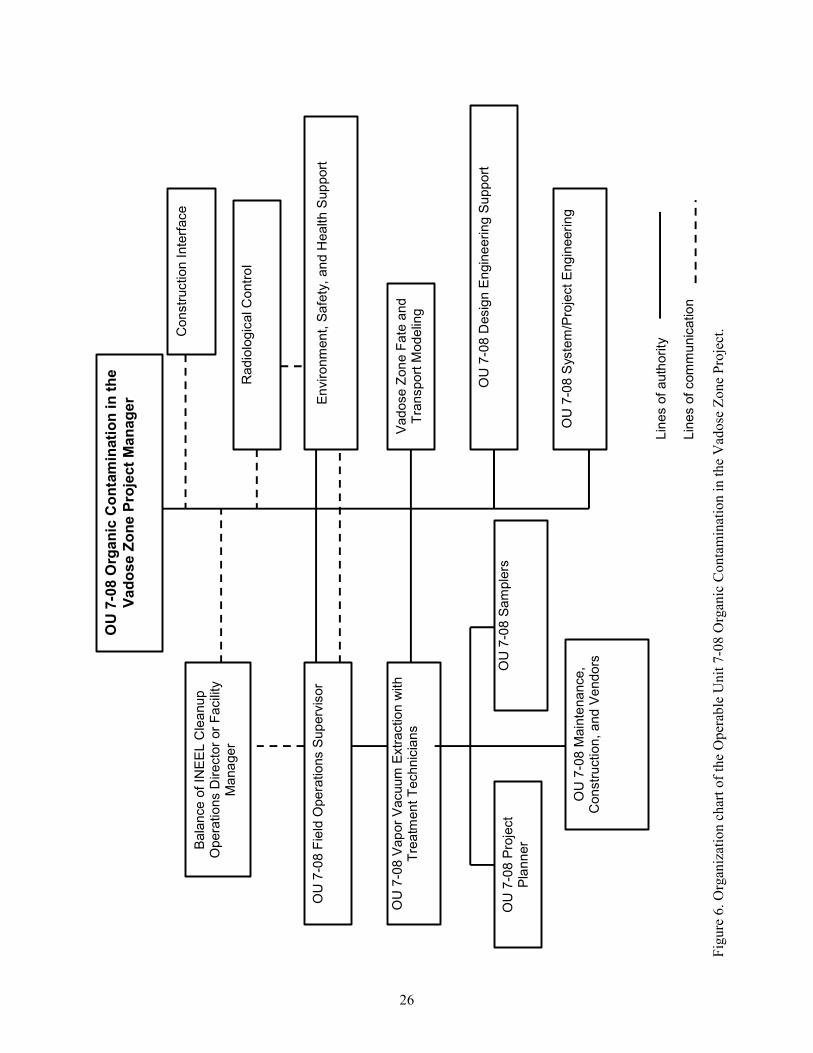
This section identifies the roles and responsibilities of key OU 7-08 Project personnel. Figure 6 presents the OU 7-08 Project organization chart.
7.1 Operable Unit 7-08 Project Personnel
7.1.1 Project Manager
The project manager is responsible for ensuring that all activities conducted during this project comply with INEEL MCPs, PRDs, and all applicable OSHA, EPA, DOE, U.S. Department of Transportation, and State of Idaho requirements. The project manager also ensures that tasks are performed in accordance with the “Project Execution Plan for the Balance of INEEL Cleanup Project” (PLN-694). The project manager coordinates all document preparation and field, laboratory, and modeling activities, and is responsible for the overall scope, schedule, and budget of the project. Additionally, the project manager interfaces with the RWMC in accordance with the “Interface Agreement between Radioactive Waste Management Complex and the Complete Balance of INEEL Cleanup Project” (IAG-20) This interface agreement defines the roles, responsibilities, approvals, and authorities between the Balance of INEEL Cleanup Project, and RWMC for all Balance of INEEL Cleanup Project activities conducted in and around the general area of the RWMC facility.
7.1.2 System or Project Engineer
The system or project engineer serves as the single point-of-contact for the project manager to resolve technical issues for each assigned VVET job from initiation to completion. The system or project engineer also provides the following:
• Weekly and monthly reports to the project manager on VVET system accomplishments, planned activities, and issues (with input from technicians, planners, and samplers)
• Technical review and approval of corrective maintenance, preventive maintenance, and predictive maintenance work control documents
• Coordination with assigned engineering personnel to complete configuration control and design criteria requirements for work orders that implement system structure and component modifications.
7.1.3 Operations Field Technician Lead
The VVET operations field technician lead is responsible for ensuring safe, efficient, reliable, and compliant VVET system operation including
• Coordinating and providing oversight for day-to-day VVET field activities and acting as the primary point of contact for access to the VVET system operation
• Interfacing with RWMC, construction, and vendor support personnel to ensure all construction and maintenance activities are conducted in accordance with the project HASP
• Assigning work activities to other VVET technicians
• Delegating lead technician responsibilities when unavailable.
26
OU
7-0
8 O
rgan
ic C
onta
min
atio
n in
the
Vado
se Z
one
Proj
ect M
anag
er
OU
7-0
8 Fi
eld
Ope
ratio
ns S
uper
viso
r
OU
7-0
8 Va
por V
acuu
m E
xtra
ctio
n w
ith
Trea
tmen
t Tec
hnic
ians
OU
7-0
8 Sa
mpl
ers
OU
7-0
8 Pr
ojec
t Pl
anne
r
OU
7-0
8 S
yste
m/P
roje
ct E
ngin
eerin
g
Vado
se Z
one
Fate
and
Tr
ansp
ort M
odel
ing
OU
7-0
8 D
esig
n E
ngin
eerin
g S
uppo
rt
OU
7-0
8 M
aint
enan
ce,
Con
stru
ctio
n, a
nd V
endo
rs
Con
stru
ctio
n In
terfa
ce
Envi
ronm
ent,
Safe
ty, a
nd H
ealth
Sup
port
Bal
ance
of I
NE
EL
Cle
anup
O
pera
tions
Dire
ctor
or F
acili
ty
Man
ager
R
adio
logi
cal C
ontro
l
Line
s of
aut
horit
y Li
nes
of c
omm
unic
atio
n
Figu
re 6
. Org
aniz
atio
n ch
art o
f the
Ope
rabl
e U
nit 7
-08
Org
anic
Con
tam
inat
ion
in th
e V
ados
e Zo
ne P
roje
ct.

27
7.1.4 Operations Field Technicians
The VVET field technicians are responsible for performing routine surveillance and operational checks including completion of the daily round sheets and operating logbooks. They provide input to the planner for work orders in accordance with STD-101, “Integrated Work Control Process,” for VVET system maintenance and upgrades and oversight, and support for VVET system monthly, quarterly, subcontractor, and annual preventive maintenance; VVET system corrective maintenance, upgrades, and instrument calibrations; maintenance and tracking of VVET system spare parts inventory; and planning, scheduling, and providing oversight for VVET system operations waste management activities. Technicians follow a VVET technician training plan and a qualification program to ensure they receive the training required to support safe performance of field activities. These activities include startup, operation, shutdown, and operational checks of the VVET units, and response to system abnormal conditions. The VVET technician training plan is provided in PLN-974, “Operable Unit 7-08 Organic Contamination in the Vadose Zone Vapor Vacuum Extraction with Treatment Technician Training Plan,” and a copy of the OU 7-08 VVET technician training qualification checklist is provided in Appendix D.
7.1.5 Planner
The planner is responsible for the following:
• Preparing required work control documents for O&M work
• Ensuring that input to work orders is obtained from the system or project engineer
• Ensuring that field walkdowns are conducted by (at a minimum) the system or project engineer or designee, safety representative, quality representative, and RWMC representative, as required
• Tracking status of work control documents
• Ordering, storing, and maintaining inventory of spare parts, as identified by the system or project engineer.
7.1.6 Vadose Zone Sampler
The vadose zone sampler is responsible for the following:
• Performing monthly and quarterly sampling of vapor-monitoring wells, VOC analysis on VVET daily operational samples and monthly and quarterly well-vapor samples
• Maintaining sampling equipment (e.g., pumps and vapor ports) and analytical equipment (i.e., Bruel & Kjar gas analyzers)
• Reporting operational sample results to assigned engineering personnel to support mass-loss calculations
• Reporting well-vapor data to assigned engineering personnel to support development of well-vapor trending reports.

28
7.1.7 Vadose Zone Fate and Transport Modeler
The vadose zone fate and transport modeler is responsible for the following:
• Developing and maintaining the OU 7-08 vadose zone fate and transport model
• Calibrating the OU 7-08 vadose zone model to subsurface gas pressure data, operations removal data, subsurface monitoring data, and inventory data
• Conducting vadose zone model sensitivity and uncertainty analyses
• Providing technical input to the project manager to support the OCVZ operations strategy.
7.2 Environment, Safety, Health, and Quality Assurance Personnel
7.2.1 Health and Safety Officer
The OCVZ Project health and safety officer (HSO) is the person assigned to the task site as the primary contact for health and safety issues. The HSO advises the VVET operations field technician lead on the safety and health aspects of the OCVZ tasks, and is authorized to stop work at the task site if any operation threatens worker or public health or safety. The HSO may be assigned other responsibilities, as stated in other sections of the project HASP, as long as they do not interfere with the primary responsibilities of safety and health. The HSO will be supported as needed by Industrial Safety, Industrial Hygiene, Environmental, and Quality Assurance support personnel. The HSO duties will be performed by the VVET field technician lead or VVET field technician, if the primary HSO is not onsite.
7.2.2 Safety Professional
The assigned OCVZ Project safety professional reviews work packages, observes operational activities, assesses compliance with the INEEL safety and health manuals, signs safe work permits, advises the VVET technician on required safety equipment, answers questions on safety issues and concerns, and recommends solutions to safety issues and concerns that arise during operations. The safety professional may conduct periodic inspections in accordance with MCP-3449, “Safety and Health Inspections,” and may have other duties at the task site as specified in the project HASP, or in INEEL PRDs or MCPs. Additionally, the safety professional will support OCVZ Project management by investigating accidents and injuries and preparing written reports to project and functional management, hazard identification, and appropriate mitigation efforts.
7.2.3 Industrial Hygienist
The assigned OCVZ industrial hygienist is the primary source for information about nonradiological hazardous and toxic agents during operations. The industrial hygienist assesses the potential for worker exposures to hazardous agents in accordance with the INEEL safety and health manual MCPs, and accepted industry IH practices and protocol. By participating in work control development and approval processes, the industrial hygienist assesses and recommends appropriate hazard controls for the protection of Operations personnel, operates and maintains airborne sampling and monitoring equipment, reviews for effectiveness, and recommends and assesses the use of PPE required in the project HASP (recommending changes as appropriate).
7.2.4 Quality Assurance Engineer
Duties and responsibilities of the quality assurance engineer include the following:

29
• Implementing internal quality monitoring, assessment, and surveillance by establishing and maintaining an internal assessment and monitoring schedule
• Reviewing design and performance specifications and other design documents to determine whether quality requirements are properly included
• Ensuring quality assurance compliance is achieved in accordance with applicable requirements established by the company, DOE, state, and federal regulations.
7.2.5 Environmental Engineer
Responsibilities of the environmental engineer include the following:
• Providing overall technical expertise with respect to regulatory issues, natural and cultural resources, and risk assessment for the OCVZ Project
• Identifying environmental and regulatory issues that affect operations and developing solutions in coordination with the OCVZ Project engineer and other project task leads
• Working with the project task leads and management to develop appropriate mitigation measures that minimize potential noncompliance with environmental requirements when environmental issues are identified.
7.3 Radiological Control
7.3.1 Radiological Engineer
The radiological engineer provides radiological engineering support within the project. Specific duties and responsibilities include acting as point of contact for all radiation protection issues related to the project, ensuring that radiological hazards are identified and appropriate controls are implemented to maintain worker exposure to those hazards as low as reasonably achievable, and identifying conditions that may impede implementation of company standards for safety, quality, and O&M. The radiological engineer is also responsible for initiating actions to correct conditions that adversely impact safety, quality, or operations and maintenance, including stopping work if necessary.
7.3.2 Radiological Control Technicians
Radiological control technicians report directly to the facility radiological control technician foreman, and are responsible for ensuring compliance with the INEEL Radiological Control program within the OCVZ Project areas, including acting as a Radiological Control information resource for project personnel. Also, during emergencies, radiological control technicians are responsible for stopping work or ordering an area evacuated when an imminent radiation hazard exists and such actions are necessary to ensure worker safety.
7.4 Maintenance, Construction, and Vendor Support Personnel 7.4.1 Laborers and Heavy Equipment Operators
Specific duties and responsibilities for laborers and heavy equipment operators include operating heavy equipment, forklifts, and industrial vehicles to transport equipment and components to the site to support construction and maintenance activities.

30
7.4.2 Mechanics and Instrument Technicians
Maintenance personnel are responsible for maintenance and repair of project operations mechanical and electrical equipment. Personnel in this category include all maintenance crafts (e.g., electricians, mechanics, pipe fitters, instrument technicians, and carpenters), life-safety-systems technicians, and associated line management. The VVET technicians are responsible for specific maintenance and monitoring activities that include equipment maintenance, troubleshooting, repair, testing, instrument calibration, inspections, and data surveys.
7.4.3 Construction Support Personnel
Construction support personnel will perform VVET upgrades and maintenance activities where required. Construction support may include, but is not limited to, equipment operators, hoisting and rigging, laborers, and similar construction trades. The VVET technician will serve as the interface for all construction personnel at the OCVZ site.
7.4.4 Vapor Vacuum Extraction with Treatment Unit Vendors
Vendors provide VVET components, upgrade equipment, and structures for the existing units. The VVET technician will serve as the interface for all vendor personnel at the OCVZ site.
7.5 Visitors All visitors with official business in the OCVZ Project operational areas (including INEEL
personnel, representatives of DOE, and state or federal regulatory agencies) may not proceed beyond the RWMC operational area without taking the appropriate training (see Table 6-1 in the project HASP) as described below:
• Receiving OCVZ HASP training or an orientation briefing for the area to be accessed
• Signing applicable entry logs and work control documents (for the area to be accessed)
• Wearing the appropriate PPE.
A VVET technician will escort visitors entering the project operational areas.
Note 1: Visitors may not be allowed into OCVZ areas during certain activities (e.g., construction or maintenance) to minimize safety, health, and radiological hazards to the visitor(s). The determination as to any visitor’s demonstrated need for access into the OCVZ Project area will be made by the VVET technician in consultation with assigned safety and health professionals and Radiological Control personnel.
Note 2: Visitors with no official business at OCVZ Project areas will not be permitted to enter project areas.

31
8. REFERENCES
29 CFR 1910, 2003, “Occupational Safety and Health Standards,” Code of Federal Regulations, Office of the Federal Register.
40 CFR 61, 2003, “National Emission Standards for Emissions of Radionuclides Other Than Radon from Department of Energy Facilities,” Code of Federal Regulations, Office of the Federal Register.
40 CFR 261, 2003, “Identification and Listing of Hazardous Waste,” Section 261.10, “Criteria for Identifying the Characteristics of Hazardous Waste,” Code of Federal Regulations, Office of the Federal Register.
40 CFR 264, 2003, “Standards for Owners and Operators of Hazardous Waste Treatment, Storage, and Disposal Facilities,” Code of Federal Regulations, Office of the Federal Register.
49 CFR 171, 2003, “General Information, Regulations, and Definitions,” Code of Federal Regulations, Office of the Federal Register.
49 CFR 173, 2003, “Shippers—General Requirements for Shipments and Packagings,” Code of Federal Regulations, Office of the Federal Register.
49 CFR 177, 2003, “Carriage by Public Highway,” Code of Federal Regulations, Office of the Federal Register.
49 CFR 178, 2003, “Specifications for Packagings,” Code of Federal Regulations, Office of the Federal Register.
49 CFR 179, 2003, “Specifications for Tank Cars,” Code of Federal Regulations, Office of the Federal Register.
15 USC § 2601 et seq., 1976, “The Toxic Substances Control Act (TSCA) of 1976,” United States Code.
42 USC § 6901 et seq., 1976, “Resource Conservation and Recovery Act of 1976 (Solid Waste Disposal Act),” United States Code.
42 USC § 9601 et seq., 1980, “Comprehensive Environmental Response, Compensation and Liability Act of 1980 (CERCLA/Superfund),” United States Code.
ACGIH, 2000, Threshold Limit Values Booklet, American Conference of Governmental Industrial Hygienist.
ACGIH, 2001, Threshold Limit Values Booklet, American Conference of Governmental Industrial Hygienist.
ANSI Z540-1, 1994, “American National Standard for Calibration—Calibration Laboratories and Measuring and Test Equipment General Requirements,” ANSI/NCSL Z540-1-94, American National Standards Institute, National Conference of Standards Laboratories.
DOE O 5820.2A, 1988, “Radioactive Waste Management,” U.S. Department of Energy.

32
DOE-ID, 1994, Record of Decision: Declaration for Organic Contamination in the Vadose Zone Operable Unit 7-08, Idaho National Engineering Laboratory, Radioactive Waste Management Complex, Subsurface Disposal Area, Administrative Record No. 5761, U.S. Department of Energy Idaho Operations Office; U.S. Environmental Protection Agency, Region 10; and Idaho Department of Health and Welfare.
DOE-ID, 2000, U.S. Department of Energy, Idaho Operations Office Idaho National Engineering and Environmental Laboratory Pollution Prevention Plan, DOE/ID-10333, Rev. 0, U.S. Department of Energy Idaho Operations Office.
DOE-ID, 2004, Idaho National Engineering and Environmental Laboratory Reusable Property, Recyclable Materials, and Waste Acceptance Criteria (RRWAC), DOE/ID-10381, Rev. 20, U.S. Department of Energy Idaho Operations Office.
EDF-1901, 2004, “Operable Unit 7-08 Air Dispersion Modeling and Health Effects from Thermal and Catalytic Oxidation Unit Emissions at the Radioactive Waste Management Complex,” Rev. 1, Idaho Completion Project.
EDF-3227, 2003, “Technical and Functional Requirements for Performance Testing of Vapor Vacuum Extraction with Treatment Units for the OU 7-08 Organic Contamination in the Vadose Zone Project,” Rev. 0, Idaho National Engineering and Environmental Laboratory.
EPA, 1995, User’s Guide for the Industrial Source Complex (ISC3) Dispersion Models, EPA-450/B-95-003a, U.S. Environmental Protection Agency.
Form 434.14, 2003, “Pre-Job Briefing Checklist,” Rev. 7, Idaho National Engineering and Environmental Laboratory.
Harvego, Lisa A., 2002, Air Monitoring Results of the Subsurface Disposal Area at the Radioactive Waste Management Complex for Operable Unit 7-08 Organic Contamination in the Vadose Zone 2001 Supplement, INEEL/EXT-2000-00039, EDF-ER-125, Rev. 0, Idaho National Engineering and Environmental Laboratory.
Housley, L. T., 2004, Field Sampling Plan for Operations And Monitoring Sampling Conducted in Support of the Organic Contamination in the Vadose Zone Remediation Project, INEEL/EXT-99-00907, Rev. 2, Idaho National Engineering and Environmental Laboratory.
IAG-20, 2004, “Interface Agreement between Radioactive Waste Management Complex and the Complete Balance of INEEL Cleanup Project,” Rev. 4, Idaho National Engineering and Environmental Laboratory.
IDAPA 58.01.01.210.10, 1995, “Idaho Demonstration of Preconstruction Compliance with Toxic Standards,” Idaho Administrative Procedures Act, Idaho Department of Environmental Quality.
IDAPA 58.01.01.577, 1994, “Ambient Air Quality Standards for Specific Air Pollutants,” Idaho Administrative Procedures Act, Idaho Department of Environmental Quality.
IDAPA 58.01.01.585, 1995, “Idaho Toxic Air Pollutants Non-Carcinogenic Increments,” Idaho Administrative Procedures Act, Idaho Department of Environmental Quality.

33
IDAPA 58.01.01.586, 2001, “Idaho Toxic Air Pollutants Carcinogenic Increments,” Idaho Administrative Procedures Act, Idaho Department of Environmental Quality.
IDAPA 58.01.01.651, 1994, “Idaho Rules for Control of Fugitive Dust,” Idaho Administrative Procedures Act, Idaho Department of Environmental Quality.
IDAPA 58.01.05.500.05, 2004, “Idaho Rules and Standards for Hazardous Waste,” Idaho Administrative Procedures Act, Idaho Department of Environmental Quality.
INEEL, 2000, Data Quality Objectives Summary Report for the Operable 7-08 Post-ROD Sampling, INEEL/EXT-2000-00814, Rev. 0, Idaho National Engineering and Environmental Laboratory.
Manual 17, 2004, Manual 17 - Waste Management, Rev. 71, Idaho National Engineering and Environmental Laboratory.
MCP-2377, 2003, “Development, Assessment, and Maintenance of Drawings,” Rev. 8, Idaho National Engineering and Environmental Laboratory.
MCP-3003, 2003, “Performing Pre-Job Briefings and Post-Job Reviews,” Rev. 11, Idaho National Engineering and Environmental Laboratory.
MCP-3449, 2003, “Safety and Health Inspections,” Rev. 3, Idaho National Engineering and Environmental Laboratory.
MCP-3534, 2001, “Use of Registered Professional Engineers,” Rev. 2, Idaho National Engineering and Environmental Laboratory.
Miller, Bruce P. and Kelly Wooley, 2003, Health and Safety Plan for Vapor Vacuum Extraction with Treatment for Operable Unit 7-08, Organic Contamination in the Vadose Zone, INEEL/EXT-03-00467, Rev. 0, Idaho National Engineering and Environmental Laboratory.
PLN-687, 2003, “Vapor Vacuum Extraction and Treatment Software Configuration Management Plan,” Rev. 2, Idaho National Engineering and Environmental Laboratory.
PLN-694, 2004, “Project Execution Plan for the Balance of INEEL Cleanup Project,” Rev. 5, Idaho Completion Project.
PLN-1240, 2004, “Test Plan for Catalytic Oxidizer Performance Testing for Operable Unit 7-08 Organic Contamination in the Vadose Zone Project,” Rev. 0, Idaho Completion Project.
Scientech, 1995, Organic Contamination in the Vadose Zone Remedial Design/Remedial Action Work Plan Operable Unit 7-08 Radioactive Waste Management Complex Subsurface Disposal Area, SCIE-COM-200-95, Scientech.
SDD-174, 2003, “OU 7-08, Organic Contamination in the Vadose Zone, Vapor Vacuum Extraction with Treatment: VVET Unit D,” Rev. 0, Idaho National Engineering and Environmental Laboratory.
SDD-175, 2004, “System Design Description for Vapor Vacuum Extraction with Treatment Units E and F for the Operable Unit 7-08 Organic Contamination in the Vadose Zone Project,” Rev. 0, Idaho National Engineering and Environmental Laboratory.

34
Soelberg, Nicholas R., 2000, Operable Unit 7-08 Test Plan for the Catalytic Oxidizer Performance Test, INEEL/EXT-2000-01406, Rev. 0, Idaho National Engineering and Environmental Laboratory.
Soelberg, Nicholas R., Ferron D. East, Roy D. Woodvine, James D. Atkinson, and L. Todd Housley, 2001, Operable Unit 7-08 Catalytic Oxidizer Performance Test Report, INEEL/EXT-2000-01611, Rev. 0, Idaho National Engineering and Environmental Laboratory.
STD-101, 2003, “Integrated Work Control Process,” Rev. 15, Idaho National Engineering and Environmental Laboratory.
TPR-1634, 2004, “VVET Units E and F Catalytic Oxidizer Startup, Operation, and Shutdown,” Rev. 4, Idaho Completion Project.
TPR-1662, 2004, “VVET Catalytic Oxidizer Startup, Operations, and Shutdown,” Rev. 5, Idaho Completion Project.
TRP-6859, 2004, “Performance Testing of Organic Contamination in the Vadose Zone Vapor Vacuum Extraction with Treatment Systems,” Rev. 1, Idaho Completion Project.

A-1
Appendix A
Unit Drawings

A-2

A-3
Appendix A
Unit Drawings This appendix contains the Vapor Vacuum Extraction with Treatment Units D, E, and F catalytic
oxidizer piping and instrumentation diagrams.

A-4

A
-5
VVET
Uni
t D
Fi
gure
A-1
. OU
7-0
8 O
CV
Z Pi
ping
and
Inst
rum
enta
tion
Dia
gram
, Uni
t D, D
raw
ing
No.
515
640,
Rev
. 10.

A
-6
Fi
gure
A-2
. OU
7-0
8 O
CV
Z V
VET
Uni
t D, W
ells
SE-
6, IE
-6, a
nd D
E-6
P&ID
, Dra
win
g N
o. 6
2299
4, R
ev. 5
.
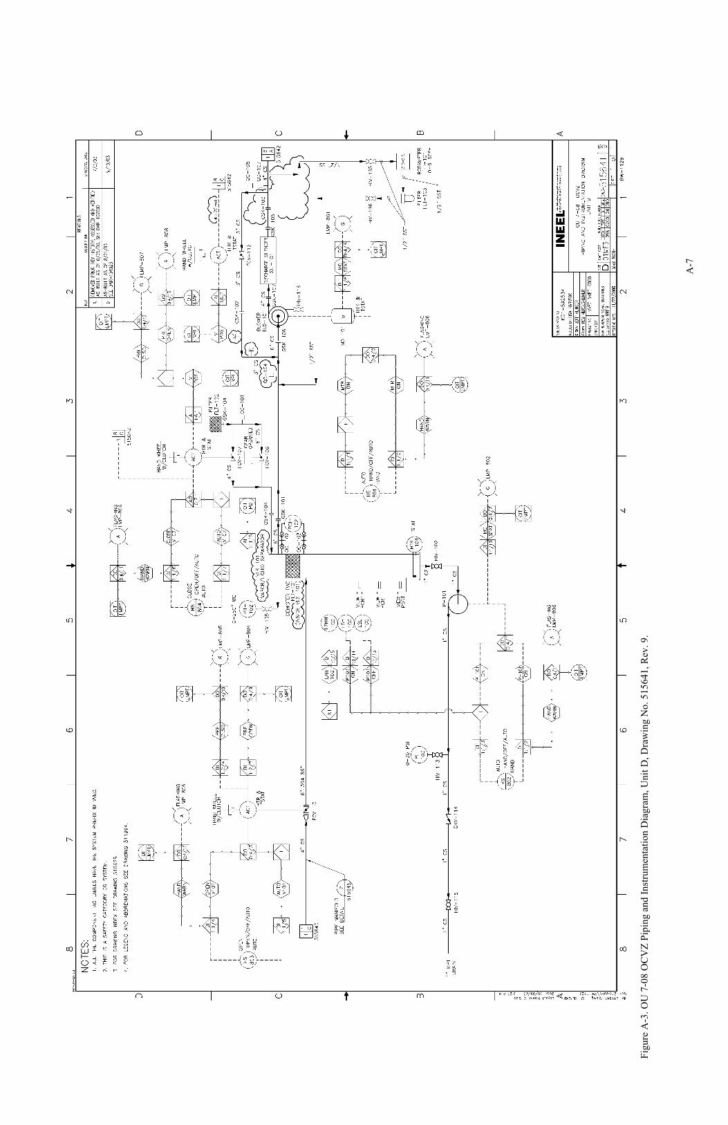
A
-7
Fi
gure
A-3
. OU
7-0
8 O
CV
Z Pi
ping
and
Inst
rum
enta
tion
Dia
gram
, Uni
t D, D
raw
ing
No.
515
641,
Rev
. 9.

A
-8
Fi
gure
A-4
. OU
7-0
8 O
CV
Z Pi
ping
and
Inst
rum
enta
tion
Dia
gram
, Uni
t D, D
raw
ing
No.
515
642,
Rev
. 9.

A
-9
Fi
gure
A-5
. OU
7-0
8 C
atal
ytic
Oxi
datio
n Sy
stem
, Uni
t D, X
FR-1
000
and
PP-6
00 O
ne L
ine,
Dra
win
g N
o. 5
1565
0, R
ev. 7
.

A
-10
Fi
gure
A-6
. GR
Oxi
dize
r Sys
tem
, Uni
t D, E
lect
rical
Pla
n an
d Pa
nel S
ched
ules
, Dra
win
g N
o. 5
1978
4, R
ev. 3
.

A
-11
VVET
Uni
t E
Fi
gure
A-7
. OU
7-0
8 O
CV
Z V
VET
Uni
t E, W
ells
SE7
, IE7
, and
DE7
Pip
ing
and
Inst
rum
enta
tion
Dia
gram
, Dra
win
g N
o. 6
2429
9, R
ev. 2
.

A
-12
Fi
gure
A-8
. OU
7-0
8 O
CV
Z V
VET
Uni
t E, W
ells
6E
and
DE1
Pip
ing
and
Inst
rum
enta
tion
Dia
gram
, Dra
win
g N
o. 6
2430
0, R
ev. 1
.

A
-13
Fi
gure
A-9
. OU
7-0
8 O
CV
Z V
VET
Uni
t E, W
ell 8
901D
Pip
ing
and
Inst
rum
enta
tion
Dia
gram
, Dra
win
g N
o. 6
2430
1, R
ev. 1
.

A
-14
Fi
gure
A-1
0. O
U 7
-08
OC
VZ
VV
ET U
nit E
, Cat
alyt
ic O
xida
tion
Syst
em In
tern
als,
Man
ifold
to S
ilenc
er, P
ipin
g an
d In
stru
men
tatio
n D
iagr
am, D
raw
ing
No.
626
166,
Rev
. 4.
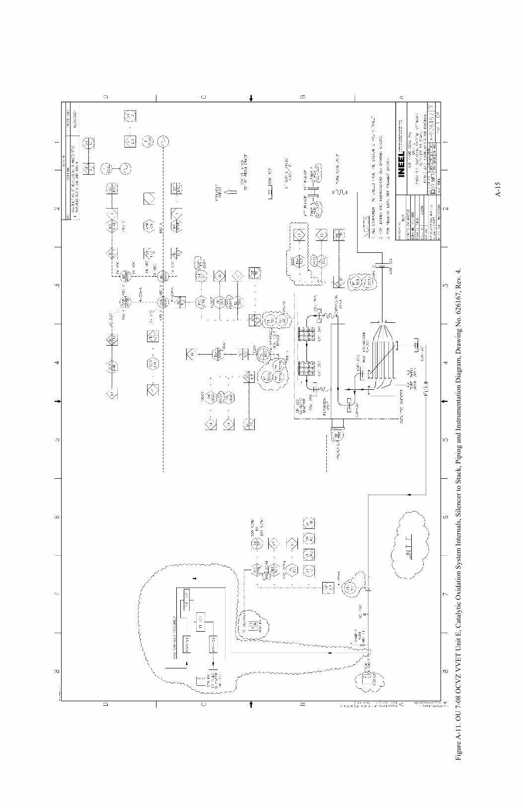
A
-15
Fi
gure
A-1
1. O
U 7
-08
OC
VZ
VV
ET U
nit E
, Cat
alyt
ic O
xida
tion
Syst
em In
tern
als,
Sile
ncer
to S
tack
, Pip
ing
and
Inst
rum
enta
tion
Dia
gram
, Dra
win
g N
o. 6
2616
7, R
ev. 4
.

A
-16
Fi
gure
A-1
2. O
U 7
-08
OC
VZ
VV
ET U
nit E
One
Lin
e D
iagr
am, D
raw
ing
No.
624
325,
Rev
. 4.

A
-17
Fi
gure
A-1
3. O
U 7
-08
OC
VZ
VV
ET U
nit E
Pan
el S
ched
ules
, Dra
win
g N
o. 6
2433
2, R
ev. 4
.

A
-18
This
pag
e is
inte
ntio
nally
left
blan
k.
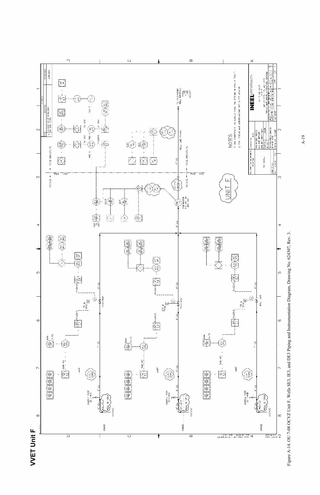
A
-19
VVET
Uni
t F
Fi
gure
A-1
4. O
U 7
-08
OC
VZ
Uni
t F, W
ells
SE3
, IE3
, and
DE3
Pip
ing
and
Inst
rum
enta
tion
Dia
gram
, Dra
win
g N
o. 6
2430
7, R
ev. 3
.

A
-20
Fi
gure
A-1
5. O
U 7
-08
OC
VZ
Uni
t F, W
ells
IE4,
DE4
, and
7E
Pipi
ng a
nd In
stru
men
tatio
n D
iagr
am, D
raw
ing
No.
624
308,
Rev
. 4.

A
-21
Fi
gure
A-1
6. O
U 7
-08
OC
VZ
Uni
t F, W
ells
IE8,
SE8
, and
DE8
Pip
ing
and
Inst
rum
enta
tion
Dia
gram
, Dra
win
g N
o. 6
2430
9, R
ev. 3
.

A
-22
Fi
gure
A-1
7. O
U 7
-08
OC
VZ
Uni
t F, W
ell 2
E Pi
ping
and
Inst
rum
enta
tion
Dia
gram
, Dra
win
g N
o. 6
2431
0, R
ev. 3
.

A
-23
Fi
gure
A-1
8. O
U 7
-08
OC
VZ
Uni
t F, C
atal
ytic
Oxi
datio
n Sy
stem
Inte
rnal
s Man
ifold
to S
ilenc
er P
ipin
g an
d In
stru
men
tatio
n D
iagr
am, D
raw
ing
No.
625
527,
Rev
. 6.

A
-24
Fi
gure
A-1
9. O
U 7
-08
OC
VZ
Uni
t F, C
atal
ytic
Oxi
datio
n Sy
stem
Inte
rnal
s Sile
ncer
to S
tack
Pip
ing
and
Inst
rum
enta
tion
Dia
gram
, Dra
win
g N
o. 6
2552
8, R
ev. 6
.

A
-25
Fi
gure
A-2
0. O
U 7
-08
OC
VZ
VV
ET U
nit F
One
Lin
e D
iagr
am, D
raw
ing
No.
624
333,
Rev
. 3.
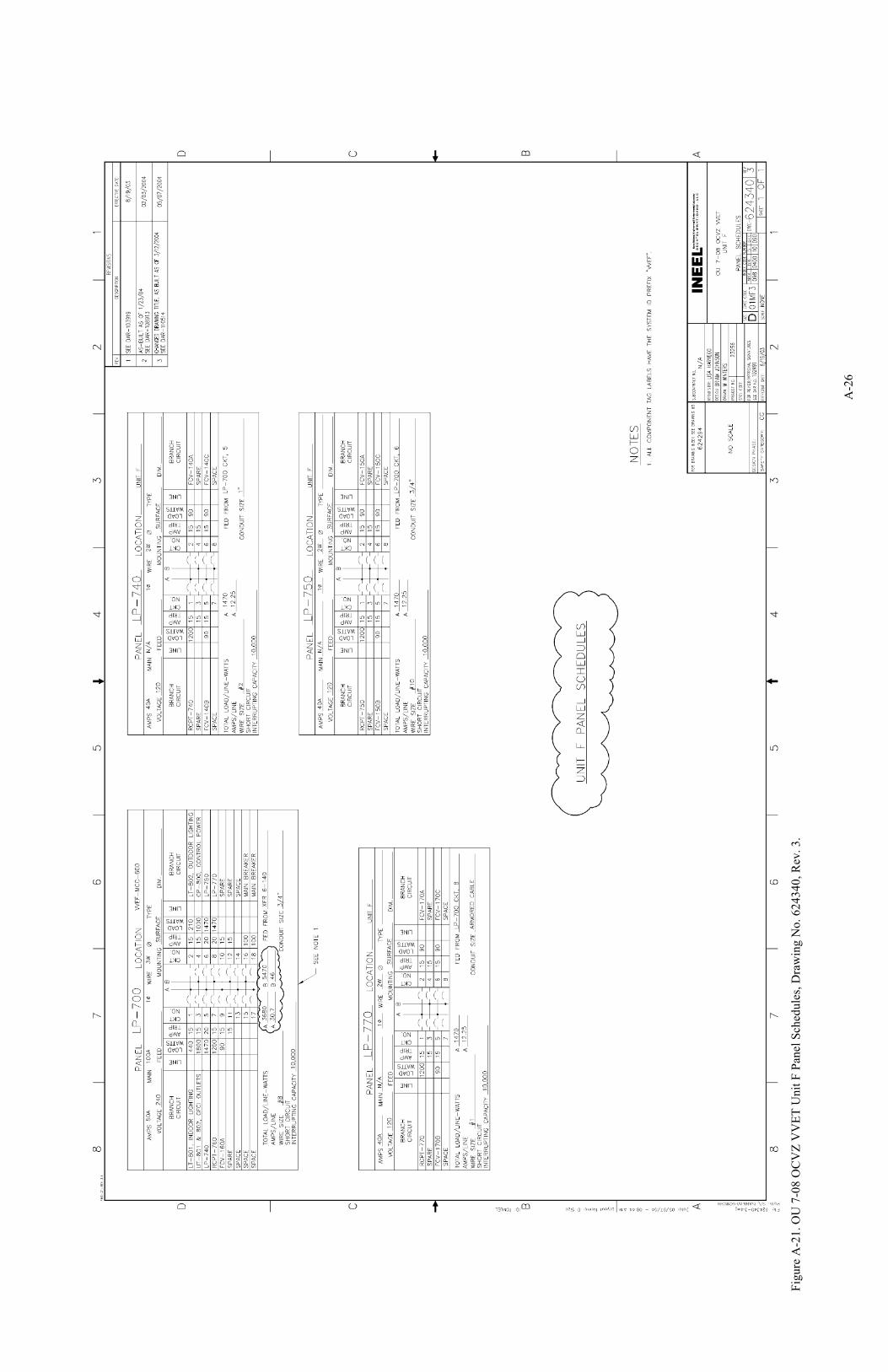
A
-26
Fi
gure
A-2
1. O
U 7
-08
OC
VZ
VV
ET U
nit F
Pan
el S
ched
ules
, Dra
win
g N
o. 6
2434
0, R
ev. 3
.

B-1
Appendix B
Technical Procedures and Logbook Sheets

B-2

B-3
Appendix B
Technical Procedures and Logbook Sheets Catalytic oxidation system warning and shutdown alarms for Vapor Vacuum Extraction with
Treatment (VVET) Unit D are detailed in Technical Procedure (TPR) -1662, “VVET Catalytic Oxidizer Startup, Operations, and Shutdown.” Alarms for VVET Units E and F are detailed in TPR-1634, “VVET Units E and F Catalytic Oxidizer Startup, Operation, and Shutdown.” Testing is performed at the Subsurface Disposal Area with the catalytic oxidizers in full-scale operation in accordance with TRP-6859, “Performance Testing of Organic Contamination in the Vadose Zone Vapor Vacuum Extraction with Treatment Systems.” Copies of these TPRs are included in this appendix
Copies of the operations logbook sheets for VVET Units D, E, and F are also included in this appendix.

B-4

B-5

B-6

B-7

B-8

B-9

B-10
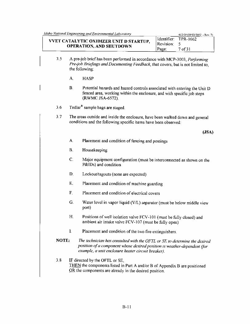
B-11

B-12

B-13

B-14

B-15

B-16

B-17

B-18

B-19

B-20
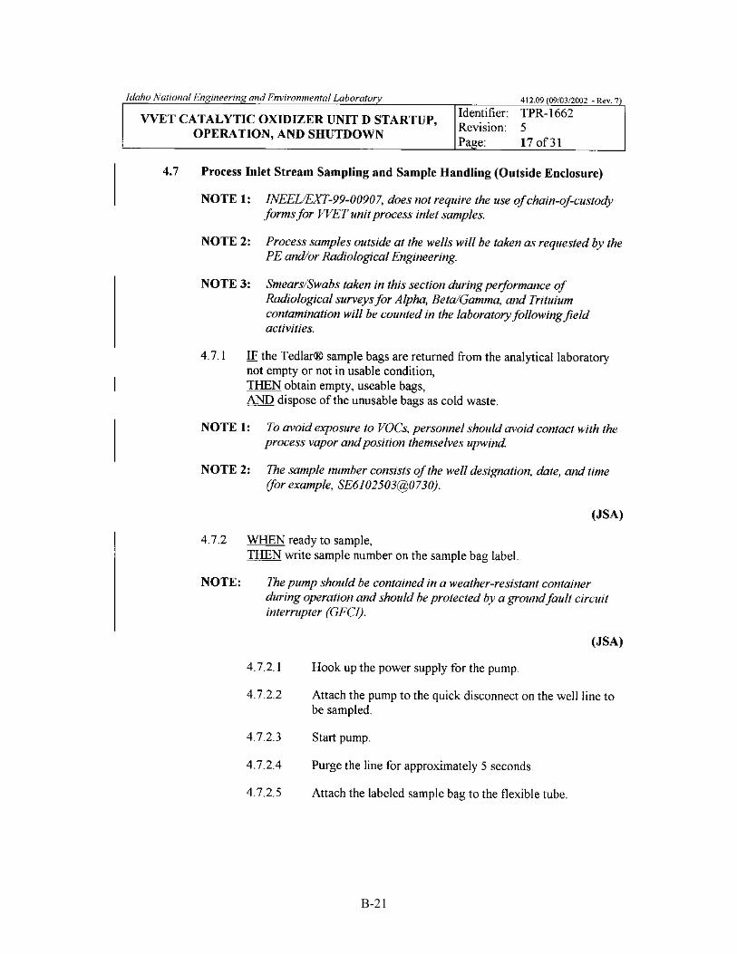
B-21

B-22

B-23

B-24

B-25
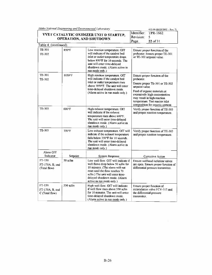
B-26

B-27

B-28

B-29

B-30

B-31

B-32

B-33

B-34

B-35

B-36

B-37

B-38

B-39
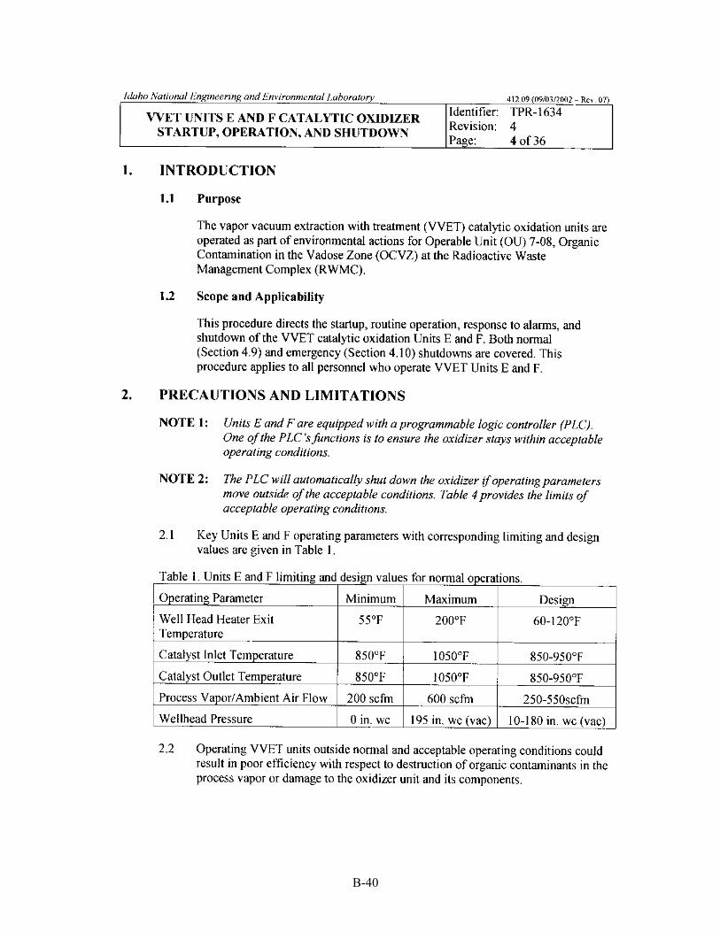
B-40

B-41

B-42
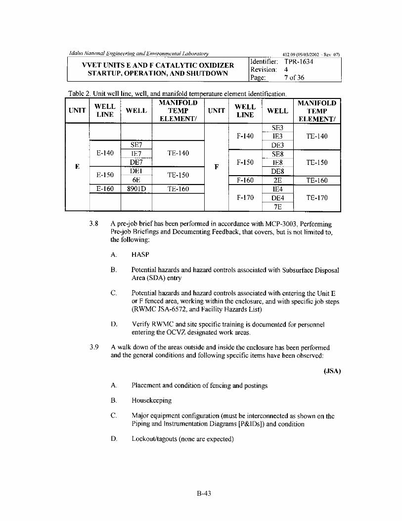
B-43

B-44

B-45

B-46

B-47

B-48

B-49

B-50
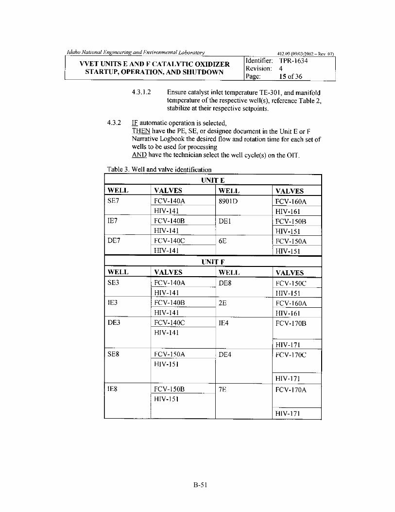
B-51

B-52

B-53

B-54

B-55

B-56

B-57

B-58

B-59

B-60

B-61

B-62

B-63

B-64

B-65

B-66

B-67

B-68

B-69

B-70

B-71

B-72

B-73

B-74

B-75
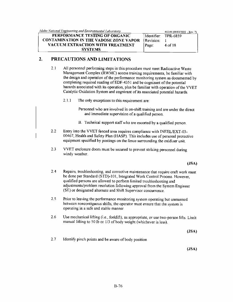
B-76

B-77

B-78

B-79

B-80
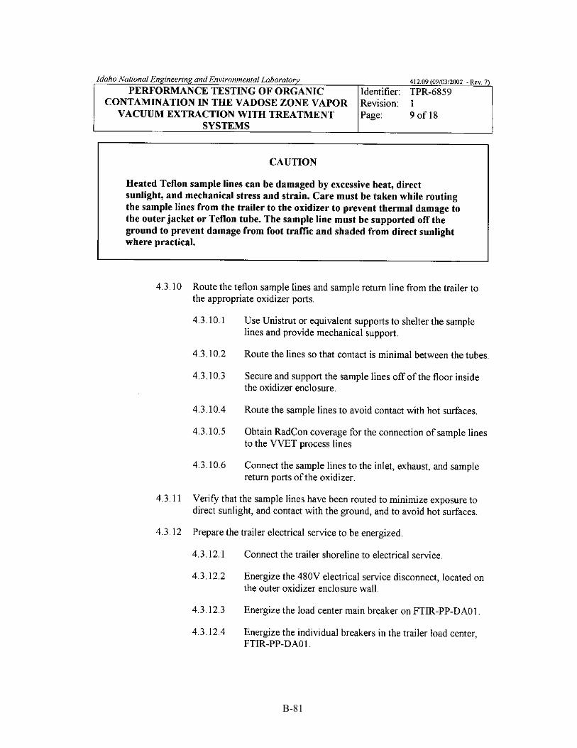
B-81

B-82

B-83

B-84
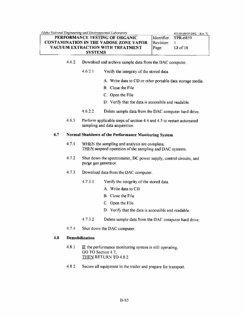
B-85

B-86

B-87
B-88

B-89
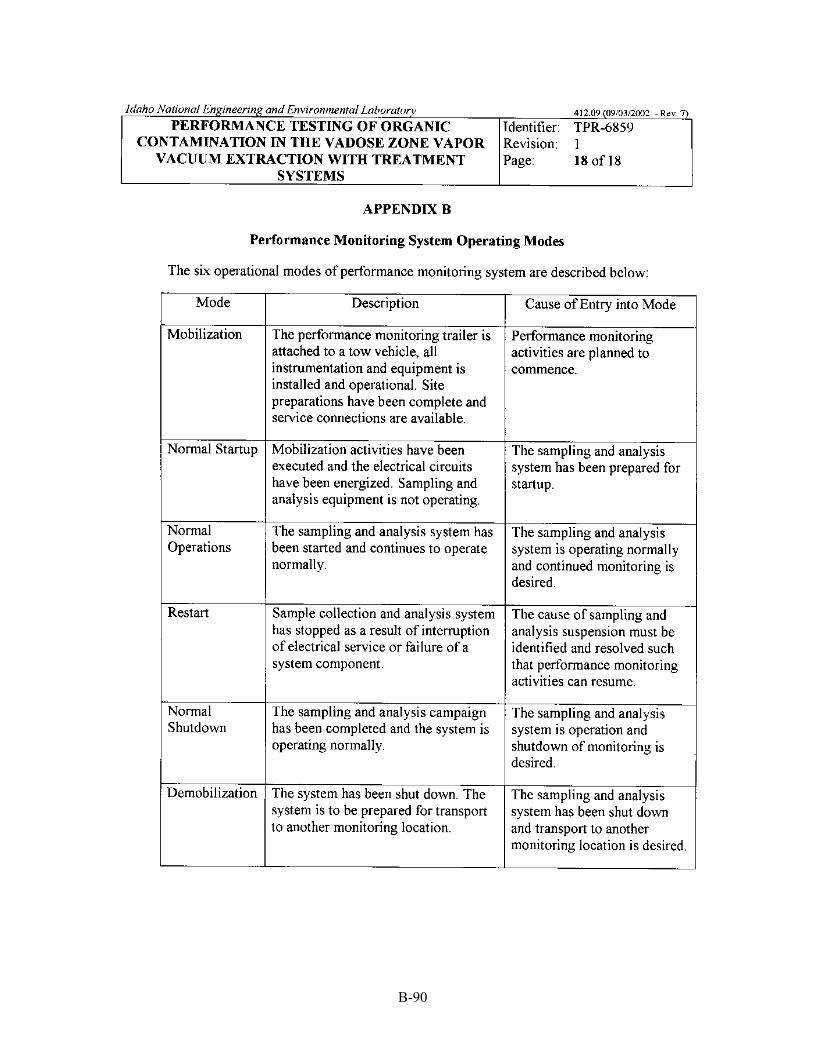
B-90

B-91
B-92

B-93

B-94
B-95

B-96

B-97

B-98

B-99

B-100

B-101
B-102

B-103

B-104

B-105

B-106

B-107

B-108

B-109

B-110

B-111

B-112

B-113

B-114

C-1
Appendix C
Correspondence

C-2

C-3
Appendix C
Correspondence This appendix contains a copy of an e-mail from Lisa Harvego that documents concurrence of the
Idaho National Engineering and Environmental Laboratory calibration laboratory with the organic contamination in the vadose zone calibration approach.

C-4
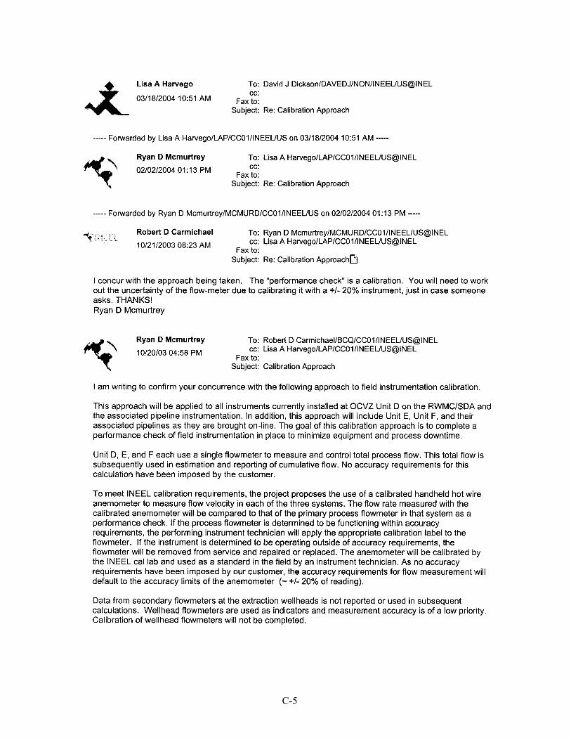
C-5

C-6

D-1
Appendix D
Technician Training Plan and Qualification Checklist

D-2

D-3
Appendix D
Technician Training Plan and Qualification Checklist This appendix contains a copy of the Operable Unit 7-08 Vapor Vacuum Extraction with Treatment
Units D, E, and F technician initial qualification checklist, which is used to technician document training achievements.

D-4
D-5

D-6

D-7

D-8

D-9

D-10

D-11
D-12

D-13

D-14

D-15

D-16

D-17

D-18

D-19

D-20

D-21

D-22