Embed Size (px)
Citation preview

Operation instructions
Final inspection test bench PV 1405

Page 2
NOTICE
Read operation instructions first.
• Observe safety instructions. • These operation instructions are part of the product. • Preserve operation instructions during product life. • Pass on instructions to any subsequent user or owner of the product.
NOTICE
Warranty claims
Failure to observe these operation instructions voids all warranty claims. (refer also to 2.3)

Page 3
TABLE OF CONTENTS
1 SAFETY INSTRUCTIONS ..................................................................... 6
1.1 General notes on safety..............................................................................................................6
1.2 Warnings and notes ...................................................................................................................7
2 GENERAL INFORMATION ................................................................... 9
3 IMPORTANT NOTES .......................................................................... 10
3.1 Transport and storage .............................................................................................................10
3.2 Operating conditions ...............................................................................................................11
3.3 Assembly and commissioning .................................................................................................11 3.3.1 Installation (electrical connection)............................................................................11 3.3.2 Commissioning ........................................................................................................11
3.4 Warranty ..................................................................................................................................12
4 UNIT DESIGN AND SCOPE OF DELIVERY....................................... 13
4.1 The PV 1405 contains the following main components ........................................................13 4.1.1 Control cabinet.........................................................................................................13 4.1.2 Transducer...............................................................................................................15 4.1.3 Measurement and control module ...........................................................................15 4.1.4 Computer connection module..................................................................................16 4.1.5 Calibration panel/fuses ............................................................................................16 4.1.6 Protective module ....................................................................................................17 4.1.7 19“ industrial PC .....................................................................................................17 4.1.8 19“ LCD monitor on monitor arm .............................................................................17 4.1.9 Remote control.........................................................................................................17
4.2 Mechanical unit........................................................................................................................18 4.2.1 Brake unit for torques up to 250 Nm........................................................................18 4.2.2 Brake unit for torques up to 1500Nm.......................................................................18 4.2.3 Brake unit for torques up to 6000Nm.......................................................................20 4.2.4 Pneumatic unit .........................................................................................................21
5 TECHNICAL INDICATIONS ................................................................ 22
5.1 Dimensions................................................................................................................................22
5.2 Switchgear ................................................................................................................................22
Page 4
5.3 Control unit “EIN” [on] and EMERGENCY OFF circuit...................................................22
5.4 Protection of current ranges ...................................................................................................23
5.5 Power outputs...........................................................................................................................23
5.6 Program sequence....................................................................................................................24
5.7 Measuring rack ........................................................................................................................24
5.8 Measuring ranges: ...................................................................................................................25 5.8.1 3-phase current measurement.................................................................................25 5.8.2 Voltage measurement..............................................................................................26 5.8.3 Measurement of real power .....................................................................................26 5.8.4 Measuring outputs: ..................................................................................................26 5.8.5 Torque measurement ..............................................................................................26
5.9 Protective module ....................................................................................................................26
5.10 Computer connection module PV 1620..................................................................................27
5.11 Remote control .........................................................................................................................27
5.12 Test bench 250/1500 Nm..........................................................................................................27
5.13 For test bench 6000 Nm...........................................................................................................27
5.14 Pneumatic unit .........................................................................................................................27
6 SAFETY INSTRUCTIONS FOR TEST UNIT ....................................... 28
6.1 Mechanical connection of the test units .................................................................................28
6.2 Electrical connection of the test units.....................................................................................28
7 CALIBRATION .................................................................................... 29
7.1 Calibration of the current measurement ...............................................................................29
7.2 Calibration of MB 1 and 2 converters....................................................................................29
7.3 Calibration of the voltage measurement ................................................................................30
7.4 Calibration of speed measurement.........................................................................................30
7.5 Calibration of real power measurement ................................................................................30
7.6 Calibration of the torque measurement.................................................................................30
8 MAINTENANCE................................................................................... 31

Page 5
8.1 Control unit ..............................................................................................................................31
8.2 Mechanics .................................................................................................................................31
9 SPARE PARTS LIST........................................................................... 32
9.1 Control cabinet.........................................................................................................................32
9.2 Brake unit .................................................................................................................................32
10 TECHNICAL DATA ............................................................................. 33
11 CERTIFICATES ................................................................................... 34
11.1 Declaration of Conformity and Declaration of Incorporation.............................................34
Page 6
1 Safety instructions 1.1 General notes on safety Standards/directives AUMA products are designed and manufactured in compliance with recognised standards and directives. This is certified in a declaration of incorporation and a declaration of conformity. The end user or the contractor of the plant must observe national laws and regulations regarding assembly, electrical connection, and commissioning on site. Safety instructions/warnings All personnel working with this device must be familiar with the safety and warning instructions in this manual and observe the instructions given. Safety instructions and warning signs on the device must be observed to avoid personal injury or property damage. Qualification of staff Assembly, electrical connection, commissioning, operation, and maintenance must be carried out exclusively by suitably qualified personnel having been authorised by the end user or contractor of the plant only. Prior to working on this product, the staff must have thoroughly read and understood these instructions and, furthermore, know and observe officially recognised rules regarding occupational health and safety. Commissioning Prior to commissioning, it is important to check that all settings meet the requirements of the application. Incorrect settings might present a danger to the application, e.g. cause damage to the valve or the installation. The manufacturer will not be held liable for any consequential damage. Such risk lies entirely with the user. Operation Prerequisites for safe and smooth operation: Correct transport, proper storage, mounting and installation, as well as careful commissioning. Only operate the device if it is in perfect condition while observing these instructions. Immediately report any faults and damage and allow for corrective measures. Observe recognised rules for occupational health and safety. Observe the national regulations. During operation, the housing warms up and surface temperatures > 60 °C may occur. To prevent possible burns, we recommend to the check surface temperature with an appropriate thermometer prior to working with device. Protective measures The end user or the contractor are responsible for implementing required protective measures on site, such as enclosures, barriers, or personal safety equipment for the staff. Maintenance To ensure safe device operation, the maintenance instructions included in this manual must be observed. Any device modification requires the consent of the manufacturer.

Page 7
No liability can be assumed for inappropriate or unintended use. Observance of these operation instructions is considered as part of the device's designated use.
WARNING
During electrical operation, certain parts inevitably carry hazardous voltages.
Work on the electrical system or equipment must only be carried out by a skilled electrician himself or by specially instructed personnel under the control and supervision of such an electrician and in accordance with the applicable electrical engineering rules.
1.2 Warnings and notes The following warnings draw special attention to safety-relevant procedures in these operation instructions, each marked by the appropriate signal word (DANGER, WARNING, CAUTION, NOTICE).
DANGER
Indicates an imminently hazardous situation with a high level of risk. Failure to observe this warning will result in death or serious injury.
WARNING
Indicates a potentially hazardous situation with a medium level of risk. Failure to observe this warning could result in death or serious injury.
CAUTION
Indicates a potentially hazardous situation with a low level of risk. Failure to observe this warning may result in minor or moderate injury. May also be used with property damage.

Page 8
NOTICE
Potentially hazardous situation. Failure to observe this warning may result in property damage. Is not used for personal injury.
Arrangement and typographic structure of the warnings
Safety alert symbol (warns of a potential personal injury hazard).
Signal word (DANGER, WARNING, CUATION, NOTICE)
DANGER
Type of hazard and respective source
Possible consequence(s) in case of non-observance (option)
Measure(s) to avoid the danger
Further measure(s)
Caution! Before opening the control cabinet the main switch must be switched to position OFF. When the control cabinet is opened, parts under voltage may be exposed. Before performing a repair or an exchange of parts, the unit must be separated from the circuit.
DANGER
Dangerous voltage at electrical connections
Electric shock possible.
Work on the electrical system or equipment must only be carried out by a skilled electrician himself or by specially instructed personnel under the control and supervision of such an electrician and in accordance with the applicable electrical engineering rules.

Page 9
Figure 1
If repair work under voltage at the open unit is unavoidable, it can only be performed by qualified and skilled workers, who know the possible dangers. A new calibration of the measuring unit can only be performed by trained personnel by observing the calibration instructions. Repairs at the measuring amplifier rack of the brake tables can only be performed when disconnected from the mains. The main switch at the control cabinet must be switched off or all electrical connections to and from the measuring rack must be disconnected.
2 General information The final inspection test bench is used for testing and setting of actuators which are equipped with 3 phase AC motors. The test unit motors for this system must be designed for a voltage of 400V AC 50 Hz.
Main switch in “OFF“ position

Page 10
The test bench allows reviewing the test units applying different voltages, if a power transformer has been integrated into the circuit. The required power and control terminals are available within the control cabinet. For all AUMA actuators of the type ranges SA 30.1 – SA 30.1 as well as SG 05.1 – SG 12.1 of the above described voltage variants are supplied with complete connecting cables or plug/socket connectors. For type ranges SA 6 – 100 and other AUMA products, connecting cables are available as option. Special adapters must be conceived for actuators not using AUMA plug/socket connectors. The manufacturer of the special adapter is responsible for the correct connection to the test system. AUMA is not liable for damage resulting from incorrect connection of a special adapter. In case of doubt, the adapters can be purchased from AUMA.
3 Important notes 3.1 Transport and storage • The test bench can only be transported in the designated container.
The test bench is protected against normal environmental conditions for approx. 6 months if stored in the undamaged original packing.
• Store in a well-ventilated, dry room. • Protect against floor dampness by storage on a wooden pallet. • Cover to protect against dust and dirt. Long-term storage If the device must be stored for a long period (more than 6 months) the following points must be observed in addition:
1. Prior to storage: Protect uncoated surfaces, in particular the parts of the brake units with
long-term corrosion protection agent. 2. At an interval of approx. 6 months:
Check for corrosion. If first signs of corrosion show, apply new corrosion protection.

Page 11
3.2 Operating conditions Operation of the PV 1405 is guaranteed for ambient temperatures from 0 – 40° C. Fluctuation of the supply voltage is only permissible within the tolerances TAB/VDE. 3.3 Assembly and commissioning 3.3.1 Installation (electrical connection) The installation of the system is performed by the client. As an option, system installation can be performed by AUMA. When implementing the electrical connection, the following points have to observed:
• Switch off voltage prior to connection • Operate the final test bench on grounded circuits only • Separately install power and control cables
DANGER
Dangerous voltage at electrical connections
Electric shock possible.
Work on the electrical system or equipment must only be carried out by a skilled electrician himself or by specially instructed personnel under the control and supervision of such an electrician and in accordance with the applicable electrical engineering rules.
3.3.2 Commissioning In any case, commissioning must be performed by a member of the AUMA staff.
Prior to commissioning and test run, the following points must be observed:
- Ensure that all electrical connections are correctly wired.
- Ensure that the permissible supply voltages at power and signal plug connections are not exceeded:
400 VAC power supply
Transformer voltages
230 VAC component supply
- Ensure correct polarity for DC voltage supplies.

Page 12
WARNING
During electrical operation, certain parts inevitably carry hazardous voltages.
Work on the electrical system or equipment must only be carried out by a skilled electrician himself or by specially instructed personnel under the control and supervision of such an electrician and in accordance with the applicable electrical engineering rules.
Die allgemeinen und regionalen Installations- und Sicherheitsvorschriften für Arbeiten an Anlagen mit gefährlichen Spannungen (z.B. EN 50178), als auch die den fachgerechten Einsatz von Werkzeugen 3.4 Warranty AUMA is not liable for damages resulting from:
• non-observance of the operation instructions, • unsuitable or improper use, • incorrect installation and/or commissioning by the buyer or
by third parties, • normal wear and tear • incorrect or careless handling, • chemical or electrochemical and electrical influences, as
long as they are not caused by a fault of AUMA, • improper modifications or repairs by the buyer or third
parties,
• effects of parts which are not AUMA original parts.

Page 13
4 Unit design and scope of delivery 4.1 The PV 1405 contains the following main components 4.1.1 Control cabinet
Phasenkontrollleuchten, Steuerung Ein, Hauptschalter und Not Aus-Schalter. Complete control (power contactors, fuses, etc.) Monitor Keyboard and mouse Proteciton module Measuring/control module Computer connection module 19“ industrial PC

Page 14
Main switch, mains fuses, control and reversing contactors, etc. Figure 2
Bild 3
Main fuses and control fuses RCD
Reversing contactors 3-ph K3/K5 1-ph K6/K7
Main contactor 1K1 MB 1 K1 MB 2 K2

Page 15
4.1.2 Transducer Current measuring ranges MB1 and MB2 Figure 4
4.1.3 Measurement and control module
The measurement and control module is used to measure mains voltage, 3-ph current and real power as well as digital inputs and outputs for system control, rotary transducer input, torque measuring input.
Bild 5
Current converter MB 1 T1/T2/T3
Current converter MB 2 T4/T5/T6
DVM to check U and 3-ph I
Reverse contact DVM

Page 16
4.1.4 Computer connection module Computer connection module for controlling and measuring the test unit, 56 channels (digital I/O), analogue I/O)
Figure 6
4.1.5 Calibration panel/fuses Calibration unit and fuses for current measuring ranges 1 and 2 incl. fault signals. Figure 7
DI/DO LEDs 56 channels
Reference voltage MWG (default setting in the factory)
Fuses and fault signals MB1 and MB2
Current calibration MB1/MB2
Current calibration via Measurement card and switch-over for MB1/MB2
Calibration DUT voltage
Page 17
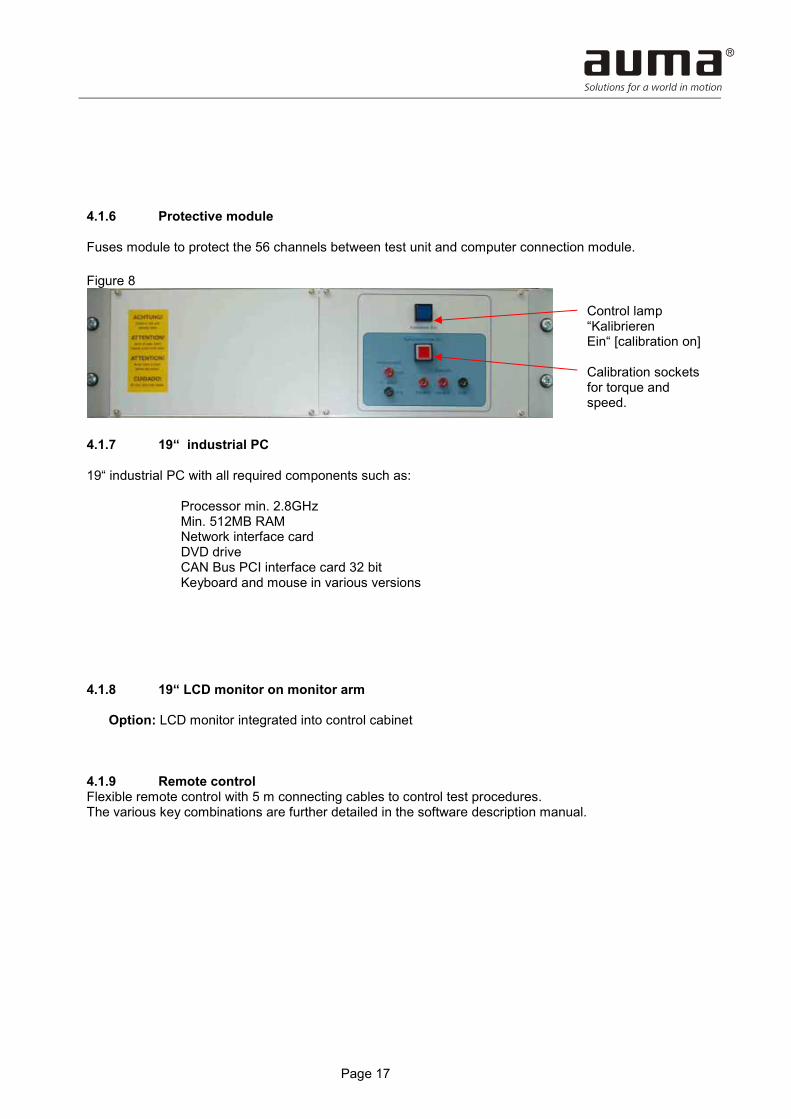
4.1.6 Protective module Fuses module to protect the 56 channels between test unit and computer connection module. Figure 8
4.1.7 19“ industrial PC 19“ industrial PC with all required components such as:
Processor min. 2.8GHz Min. 512MB RAM
Network interface card DVD drive CAN Bus PCI interface card 32 bit Keyboard and mouse in various versions 4.1.8 19“ LCD monitor on monitor arm Option: LCD monitor integrated into control cabinet 4.1.9 Remote control Flexible remote control with 5 m connecting cables to control test procedures. The various key combinations are further detailed in the software description manual.
Control lamp “Kalibrieren Ein“ [calibration on] Calibration sockets for torque and speed.

Page 18
Figure 9
4.2 Mechanical unit 4.2.1 Brake unit for torques up to 250 Nm • Flanges and adapters according to the order • Disc brake with two callipers • Incremental speed transmitter with 360 impulses/turns (3,600 impulses as option) • Torque sensor 1 kN • Torque sensor supply unit and measuring amplifier with digital display (figure 11) 4.2.2 Brake unit for torques up to 1500Nm • Flanges and adapters according to the order • Disc brake with two callipers • Incremental speed transmitter with 360 impulses/turns (3,600 impulses as option) • Torque sensor 3 kN • Torque sensor supply unit and measuring amplifier with digital display (figure 11)

Page 19
Figure 10
CAUTION
Injury hazard!
Never remove covers during instrument operation.
Never reach into running/turning system.
Figure 11 (Torque sensor supply unit)
DMS sensor Brake disc Brake calliper Rotary transducer
Digital display Manual change-over 250 Nm/1500 Nm Measuring amplifier Interface torque signal

Page 20
4.2.3 Brake unit for torques up to 6000Nm • Flanges and adapters according to the order • 2 disc brakes with 2 callipers each • Incremental speed transmitter with 360 impulses/turns (3,600 impulses as option) • Torque sensor 10kN • Torque sensor supply unit and measuring amplifier with digital display (figure 11) Figure 12
CAUTION
Injury hazard!
Never remove covers during instrument operation.
Never reach into running/turning system.
Callipers Brake disc DMS sensor Rotary transducer

Page 21
4.2.4 Pneumatic unit The unit is used to control the different brakes or the individual callipers of the disc brakes. • Supply with at least 7 bar air pressure must be ensured. Attention! Compressed air must
by dry. • Steel housing 380*380*240 mounted to the rear of the mechanical part 1500 Nm, for 6000
Nm as option integrated into mechanical part 6000 Nm. • 6 single solenoid valves to control the callipers • Proportional valve to progressively apply load to the test unit. • Maintenance unit for pressure regulation and water separation Figure 13
Solenoid valves Maintenance unit with manometer Proportional valve Supply connection for compressed air Outlets for brake callipers

Page 22
5 Technical indications 5.1 Dimensions Control cabinet: W/H/D 820x2300x600 mm Enclosure protection: IP50 5.2 Power section By turning on the main switch the supply voltage is applied to the main contactor. The indication lights H1, H2, H3 (L1/L2/L3) at the control cabinet must be switched to “Ein“ (on). Figure 14
The test bench is protected be 3 Neozed fuses (D02), Ampere rating 63 A. Indication lights H1, H2, H3 are individually protected via circuit breakers. In this operation status, computer, computer connection module, torque measurement devices and measurement rack are supplied with voltage. The computer starts automatically as soon as the main switch is switched on. In case the RCD trips, the PC keeps running as it is not connected via the residual current device. 5.3 Control unit “EIN” [on] and EMERGENCY OFF circuit The control unit is switched on via an external button panel, located at the left side of the mechanical brake unit 250 Nm.
Indication light “Phase control“ Indication light “Control unit Ein [on]“

Page 23
Figure 15
This casing houses the external EMERGENCY OFF switch. A further EMERGENCY OFF button is integrated within the control cabinet just below the main switch. The condition that the control unit is switched “EIN“ [on], is indicated by the respective indication light being illuminated at the control cabinet, above the main switch. (refer also to figure 14) Likewise, the indication light “Control unit ON” of the button panel described above is illuminated. 5.4 Protection of current ranges The test bench disposes of 2 current measuring ranges which can be selected via computer. Current range 1 is protected by 3 fuses (max. 700 V) at 25 A, current range 2 by 3 fuses (max. 700 V) at max. 63 A. These fuses are monitored by a motor circuit breaker switch. In case one or more fuses are blown due to overload, the motor circuit breaker initiates a fault signal to the corresponding computer input. The system signals “Default range 1 or default range 2“. Red warning lights at the calibration unit (figure 7) additionally indicate which current range is at default. Likewise, the red warning light at the external button panel is illuminated. 5.5 Power outputs The test bench is equipped with 2 power outputs. Output 1 leads the motor power to the AUMA plug/socket connector ELS 100. Output 2 leads the motor power to a CEE plug connector 63 A. The selection of the corresponding output is made by the computer and depends on the characteristics of the test unit which are described on the pertaining data sheet. In addition, selection can be made manually within a test program (refer to software description manual).
Emergency off Control unit “ON“ Control unit “OFF“

Page 24
A T T E N T I O N !
DANGER
Dangerous voltage at electrical connections
Electric shock possible.
Work on the electrical system or equipment must only be carried out by a skilled electrician himself or by specially instructed personnel under the control and supervision of such an electrician and in accordance with the applicable electrical engineering rules.
If actuators are tested for which output 2 must be used, particular attention of the person performing the test is required. • Only persons with advanced training level are allowed to perform these tests
(trained personnel). • Before plugging the control plug to the test unit, the motor must be connected correctly.
(Plug in CEE plug only once the motor has been connected.) • Then connect control plug onto test unit. • Switch on control unit at the test bench and automatically perform the test procedure. • Upon termination of the test, when dismounting the test unit, perform steps in reverse
order. 5.6 Program sequence Control of the power contactors essentially takes place during program sequence. The main contactors are additionally electrically interlocked so that no short circuits are generated due to malfunction of the control unit. 5.7 Measuring rack The measuring rack of PV 1405 holds the following components: (refer also to figure 5)
• Power supply unit • 3-phase current measurement module • 1-phase current measurement module • Voltage divider for voltage measurement module • Analogue inputs and outputs of the test bench • Digital inputs and outputs of the test bench • Rotary transformer input of the test bench • Reversible DVM (digital voltmeter) for calibration (figure 5).

Page 25
Figure 16
Figure 17
The measuring rack is supplied with an auxiliary voltage of 230 V AC. Connection is made via a rubber connector 16 A and internally protected via a 16 A circuit breaker. 5.8 Measuring ranges: 5.8.1 3-phase current measurement Current measurement is divided into the ranges MB1 and MB2. The current ranges were defined with the order of the PV 1405 and can be checked in the order confirmation or on the calibration certificate. Each current measurement range disposes of 3 current converters at a secondary current of 1 A. The MB1 measuring range is activated without connecting the change-over signal. The MB2 measuring range is activated via the measurement and control module.
PSU (hidden) 1-ph voltage measurement module Relay modules 3-ph current measurement module
Ethernet-controlled bus module including: Analogue inputs and output Digital inputs and output Rotary transducer input Power measurement

Page 26
5.8.2 Voltage measurement The voltage to be measured has to be applied at the calibration panel. Phases L1 and L2 must be used. The voltage to be measured is reduced via a precision voltage divider (Z028.694/01) and supplied to the measuring amplifier. The calibration of the voltage measurement is performed via a calibration panel by applying a series of calibrated AC voltages between 0 and 700 Volt AC. 5.8.3 Measurement of real power The real power measurement is calibrated via a comparison measurement by using a power analyzer. The different phase angles are simulated via a phase shift generator at a current of approx 1 A. . 5.8.4 Measuring outputs: The output signals of the measuring card for the currents L1, L2, L3 are standardised to:
0 – 10 V DC for 0 – 1 A AC. The output signal of the measuring card for the supply voltage is standardized to:
0 – 10 V DC for 0 – 1,000 V AC. 5.8.5 Torque measurement The torque is shown full scale by means of a signal between 0 and 20 mA. 5.9 Protective module The protective module has two parts. Part 1: The cables from the test unit are led via the protective module and protected with 100 mA. These cables are lead via the computer connection module. The channels connected to the computer connection module are led via part 2 of the protective module. Part 2: Besides the fuses, this module contains the overvoltage derivations which short-circuit an impermissible voltage signal (DC higher than 30 V and each AC voltage) and switch off the circuit by tripping the fuses.

Page 27
5.10 Computer connection module PV 1620 Please refer to separate description. 5.11 Remote control The remote control allows the operator to control the test without using a keyboard. 5.12 Test bench 250/1500 Nm The measuring amplifier for the torque sensors 250/1500 Nm are jointly supplied within the PV 1040.3 (refer to figure 11). The respectively desired amplifier can be selected by the measuring system (computer). Without change-over signal, the range 250 Nm is working. A positive change-over signal switches over to the range 1500 Nm. The switch-over of the rotary transducers of both test benches is performed simultaneously with the measuring amplifier change-over. In case of troubleshooting, change-over can be performed manually by using the button within the PV 1040.3. 5.13 For test bench 6000 Nm The measuring amplifier for the torque sensor 6000 Nm is supplied within the PV 1040.4 (refer to figure 11). In opposition to the PV 1040.3, the PV 1040.4 is equipped with one measuring amplifier only. Upon request, this devise is selected by the measuring system (computer). The switch-over of the respective rotary transducers is performed simultaneously with the measuring amplifier change-over. 5.14 Pneumatic unit The pneumatic cabinet (refer to figure 14) contains 6 single solenoid valves to control the individual callipers. The compressed air is transported via a maintenance unit to a proportional valve. The output of the proportional valve is sent to the parallel wired inputs of the single solenoid valves. The maintenance unit is to be set at approx. 7 bar. The setpoint voltage for the proportional valve is 0 – 10 V DC for 0 – 6.5bar.

Page 28
6 Safety instructions for test unit 6.1 Mechanical connection of the test units 2 mechanical test benches are available for the adaption of the test units. • Test bench 1 measuring range 0 – 250Nm • Test bench 2 measuring range 0 – 1500Nm The actuators are to be mounted properly and correctly to the suitable test bench by using the correct and undamaged adapter. Use all available screw connection possibilities.
CAUTION
Test unit fixing
The test unit must always be sufficiently fastened to the test bench before operation.
NOTICE
Consequences of insufficient fastening An actuator which is not fastened sufficiently to the test bench can break away. Severe physical damage to the operating staff Damage on the test bench or test unit
6.2 Electrical connection of the test units For the electrical connection of all test units he following always applies: • Switch off control unit via “OFF” button (refer to figure 15) • Check whether actuator is mounted correctly. • In case of separate motor terminal board, connect motor first. Thereto the supplied
motor connection cable is used. This cable is supplied with a 63 A CEE plug. The provided socket is located at the brake table. For safety reasons remove this connection before connecting the motor.
• After correct motor connection, the control unit is connected via plug connections or terminals, depending on the type of test unit.
• Now the CEE plug connection (63A) can be performed. • Turn on the control unit by via push button “ON“ (refer to figure 15). • Start computer test program.

Page 29
WARNING
During electrical operation, certain parts inevitably carry hazardous voltages.
Work on the electrical system or equipment must only be carried out by a skilled electrician himself or by specially instructed personnel under the control and supervision of such an electrician and in accordance with the applicable electrical engineering rules.
• When using the AUMA plug/socket connector with integral motor plug, the control unit
must be switched off first. • Establish plug/socket connection and turn on the control unit. • Start computer test program.
7 Calibration 7.1 Calibration of the current measurement During the first calibration step the ammeter board in the measuring rack must be calibrated. The following procedure is to be performed: • Start test program and activate calibration menu. • Set test bench to the calibration mode (also refer to software description) • Set the respective phase to be tested to the DVM by using the selector switch. • Set calibration mode to direct (refer to figure 7) • Feed 0 - 1 A AC at the test terminals of the measurement module (all 3 phases). • Read values from DVM as well as in the calibration menu record accordingly. If the result is negative, remove the board, repair and recalibrate, as required. 7.2 Calibration of MB 1 and 2 converters • Activate the desired measuring range MB 1 or MB 2 via the calibration menu. • Feed the appropriate primary current at the sockets for current calibration (considering the
appropriate range input) on the calibration panel (refer to figure 7) (all 3 phases subsequently).
• Read values in the calibration menu and record accordingly.

Page 30
In case of positive result: Calibrate next signal. In case of negative result: Replace the possibly inaccurate measuring transformer and repeat the test.
7.3 Calibration of the voltage measurement • Apply 0 – 700 V AC to the corresponding test sockets on the calibration panel. • Read values in the calibration menu and record accordingly.
In case of positive result: Calibrate next signal.
In case of negative result:
Remove voltage measurement board, repair if required, recalibrate and repeat test. 7.4 Calibration of speed measurement • Feed square wave signals at a level of 24 V at the appropriate test sockets on the
calibration panel (at protection module, refer to figure 8). • Read values on the computer and record accordingly. •
In case of positive result: Calibrate next signal. In case of negative result:
Replace rotary transducer module, repeat test. 7.5 Calibration of real power measurement For calibrating the real power measurement, a comparison measurement via power analyzer is required. 7.6 Calibration of the torque measurement For calibrating the torque measurement, calibrated torques are to be applied across the complete measuring range at the appropriate test bench. This is performed using a special torque calibration device. For this, the appropriate brake must be activated via the calibration menu. The fed-in torques can be read in the calibration menu. They are compared to the reference measurement unit of the calibration device. Then they are recorded into the test protocol. The max. permissible deviation is defined in the calibration certificate or in the inspection specification. For deviations outside the tolerance, shut down the test bench until correct operation is restored.

Page 31
8 Maintenance (also refer to maintenance plan PV 1405) 8.1 Control unit We recommend subjecting the entire measuring unit chain to recalibration once a year. In addition, the wear parts of the control unit (contactors) should be inspected for burn when operated frequently. Experience shows that there is hardly any wear when correctly used.
WARNING
During electrical operation, certain parts inevitably carry hazardous voltages.
Work on the electrical system or equipment must only be carried out by a skilled electrician himself or by specially instructed personnel under the control and supervision of such an electrician and in accordance with the applicable electrical engineering rules.
8.2 Mechanics It is recommended to clean the brake discs using a fat and dirt dissolving liquid at an interval according to frequency of operation. The dehydrating filter pneumatic unit has to be checked on a regular basis for condensation a. Drain condensate if required.
CAUTION
Injury hazard!
Never remove covers during instrument operation.
Never reach into running/turning system.

Page 32
9 Spare parts list 9.1 Control cabinet
Type Designation Order No. E Fuse 16A 690V cylindric P000.547 E Fuse 25A 690V cylindric P000.548 E Fuse 32A 690V cylindric P000.509 E Fuse 50A 690V cylindric P000.510 E Fuse 63A 690V cylindric P001.029 E Micro-fuse 200mA F 5x20mm K002.392 E Fuses board 15 channels with diodes Z029.945/01 E Fuses board 15 channels w/o diodes Z029.945/02 E Power supply unit 230VAC +-15V/24VDC Z031.042/01 E Current measurement board 3-ph Z038.412/01 E Voltage measurement board 1-ph Z025.431/01 E Voltage divider for voltage measurement Z028.694/01 E Relay board 8 channel for PV1620 Z039.202/01
Type B = Sub-assembly Type E = Component Other spare parts on request! 9.2 Brake unit
Type Designation Order No. E Measurement amplifier for torque Z023.783/01 E Rotary transformer 360 impusles K004.084 E Rotary transformer 3,600 impulses P000.635 E Torque sensor 1kN K004.116 E Torque sensor 3kN K004.706 E Torque sensor 10kN K004.911 E Solenoid valve 3/2 ways K005.082 E Proportional valve 0..6 bar/0..10V K004.954 E Maintenance unit G3/8 0.5..10 bar K004.953
Type B = Sub-assembly Type E = Component Other spare parts on request!

Page 33
10 Technical data Features and functions of control unit Dimensions (W – H - D) 820 x 2,300 x 600 mm Weight Approx. 200 kg Ambient temperatures 0 °C to 40 °C Enclosure protection IP 50 Connection voltage 3ph - 400V AC 50Hz Rating of blinker transmitter Max. 18 kW as an option max. 22 kW Voltage measurement 0 – 700 V AC
Accuracy ≤ ± 0.5 % of the measuring range end value 16 bit resolution
Current measurement Various ranges (5 A…200 A) 3-ph) Accuracy ≤ ± 0.5 % of the measuring range end value 16 bit resolution
Torque measurement Various ranges 250 Nm, 1,500 Nm and 6,000 Nm depending on the built-on brake bench Accuracy ≤ ± 0.5 % of the measuring range end value 16 bit resolution
Speed measuring 1 - 500 rpm Accuracy ≤ ± 0.1% 32 bit resolution
Features and functions of brake bench 250 Nm and 1,500 Nm Dimensions (W – H - D) 780 x 855 x 900mm Weight Approx. 200 kg Ambient temperatures 0 °C to 40 °C Enclosure protection IP 50 Connection voltage 230 V AC is supplied via the PV1405 Torque sensor (DMS) 1 kN at 250 Nm/3 kN at 1,500 Nm Rotary transducer 360 impulses/turn, as an option 3,600 impulses/turn Features and functions of brake bench 6000 Nm Dimensions (W – H - D) 1200 x 855 x 725 mm Weight Approx. 300 kg Ambient temperatures 0 °C to 40 °C Enclosure protection IP 50 Connection voltage 230V AC is supplied via PV1405 Torque sensor (DMS) 10 kN Rotary transducer 360 impulses/turn, as an option 3,600 impulses/turn Option: Features of transformer (also refer to transformer data sheet) Dimensions Depending on type/performance Primary voltage 3-ph – 400 V AC Secondary voltages 3-ph 0 - 700V AC others available upon customer demand. Power Depending on type between 23.9 kVA and 60.6 kVA or upon
customer demand.

Page 34
11 Certificates 11.1 Declaration of Conformity and Declaration of Incorporation

Page 35

Certificate Registration No.12 100/104 4269
www.auma.com
AUMA Riester GmbH & Co. KGP.O. Box 136279373 Müllheim, [email protected]
+49 7631 - 809-0+49 7631 - 809 1250
+49 711 - 34803 0+49 711 - 34803 34
AUMA Riester GmbH & Co. KGP. O. Box 1151D - 73747 [email protected]
For detailed information on AUMA products, refer to the InternetY004.880/003/en/1.09
EuropeAUMA Riester GmbH & Co. KGPlant MüllheimDE-79373 MüllheimTel +49 7631 809 - 0Fax +49 7631 809 - [email protected] Ostfildern-NellingenDE-73747 OstfildernTel +49 711 34803 - 0Fax +49 711 34803 - [email protected] Center CologneDE-50858 KölnTel +49 2234 2037 - 9000Fax +49 2234 2037 - [email protected] Center MagdeburgDE-39167 NiederndodelebenTel +49 39204 759 - 0Fax +49 39204 759 - [email protected] Center BavariaDE-85386 EchingTel +49 81 65 9017- 0Fax +49 81 65 9017- [email protected] Armaturenantriebe GmbHAT-2512 TribuswinkelTel +43 2252 82540Fax +43 2252 [email protected] (Schweiz) AGCH-8965 BerikonTel +41 566 400945Fax +41 566 [email protected] Servopohony spol. s.r.o.CZ-10200 Praha 10Tel +420 272 700056 / 704125Fax +420 272 [email protected] AUMATOR ABFI-02230 EspooTel +358 9 5840 22Fax +358 9 5840 [email protected] France S.A.R.L.FR-95157 Taverny CedexTel +33 1 39327272Fax +33 1 [email protected] ACTUATORS Ltd.GB- Clevedon Nort_inth Somerset BS216QHTel +44 1275 871141Fax +44 1275 [email protected] ITALIANA S.r.l. a socio unicoIT-20023 Cerro Maggiore (MI)Tel +39 0331 51351Fax +39 0331 [email protected] BENELUX B.V.NL-2314 XT LeidenTel +31 71 581 40 40Fax +31 71 581 40 [email protected]
AUMA Polska Sp. z o.o.PL-41-310 Dabrowa GórniczaTel +48 32 261 56 68Fax +48 32 261 48 [email protected] Priwody AUMARU-Moscow a/ya 11Tel +7 495 221 64 28Fax +7 495 221 64 [email protected] ARMATUR ABSE-20039 MalmöTel +46 40 311550Fax +46 40 [email protected]ØNBECH & SØNNER A/SDK-2450 København SVTel +45 33 26 63 00Fax +45 33 26 63 [email protected] S.A.ES-28027 MadridTel +34 91 3717130Fax +34 91 [email protected]. G. Bellos & Co. O.E.GR-13671 Acharnai AthensTel +30 210 2409485Fax +30 210 [email protected] SØRUM A. S.NO-1300 SandvikaTel +47 67572600Fax +47 [email protected] SintraTel +351 2 1910 95 00Fax +351 2 1910 95 [email protected] Endüstri Kontrol Sistemieri Tic. Ltd. Sti.TR-06810 AnkaraTel +90 312 217 32 88Fax +90 312 217 33 [email protected] Control Limited Liability CompanyUA-02099 KiyivTel +38 044 566-9971, -8427Fax +38 044 [email protected]
AfricaAUMA South Africa (Pty) Ltd.ZA-1560 SpringsTel +27 11 3632880Fax +27 11 [email protected] CairoTel +20 2 23599680 - 23590861Fax +20 2 [email protected]
AmericaAUMA ACTUATORS INC.US-PA 15317 CanonsburgTel +1 724-743-AUMA (2862)Fax +1 [email protected] Automação do Brasil ltda.BR-Sao PauloTel +55 11 [email protected]
AUMA Chile Representative OfficeCL- La Reina Santiago de ChileTel +56 22 77 71 51Fax +56 22 77 84 [email protected] S. A.AR-C1140ABP Buenos AiresTel +54 11 4307 2141Fax +54 11 4307 [email protected] Ferrostaal de Colombia Ltda.CO- Bogotá D.C.Tel +57 1 401 1300Fax +57 1 416 5489dorian.hernandez@manferrostaal.comwww.manferrostaal.comPROCONTIC Procesos y Control AutomáticoEC- QuitoTel +593 2 292 0431Fax +593 2 292 [email protected] International S.A.C.PE- Miralflores - LimaTel +511444-1200 / 0044 / 2321Fax [email protected] Inc.PR-00936-4153 San JuanTel +18 09 78 77 20 87 85Fax +18 09 78 77 31 72 [email protected] Maracaibo Estado, ZuliaTel +58 261 7 555 667Fax +58 261 7 532 [email protected]
AsiaAUMA Actuators (Tianjin) Co., Ltd.CN-300457 TianjinTel +86 22 6625 1310Fax +86 22 6625 [email protected] (INDIA) PRIVATE LIMITEDIN-560 058 BangaloreTel +91 80 2839 4655Fax +91 80 2839 [email protected] JAPAN Co., Ltd.JP-210-0848 Kawasaki-ku, Kawasaki-shiKanagawaTel +81 44 329 1061Fax +81 44 366 [email protected] ACTUATORS (Singapore) Pte Ltd.SG-569551 SingaporeTel +65 6 4818750Fax +65 6 [email protected] Actuators Middle East W.L.L.AE- 15268 Salmabad 704Tel +973 [email protected] CONTROLS Ltd.HK- Tsuen Wan, KowloonTel +852 2493 7726Fax +852 2416 [email protected] Controls Co., Ltd.KR-153-803 Seoul KoreaTel +82 2 2113 1100Fax +82 2 2113 1088/[email protected]
Sunny Valves and Intertrade Corp. Ltd.TH-10120 Yannawa BangkokTel +66 2 2400656Fax +66 2 [email protected]/Top Advance Enterprises Ltd.TW- Jhonghe City Taipei Hsien (235)Tel +886 2 2225 1718Fax +886 2 8228 [email protected]
AustraliaBARRON GJM Pty. Ltd.AU-NSW 1570 ArtarmonTel +61 294361088Fax +61 [email protected]
2009-01-01

![High Court Judgment Template - Keating Chambers · neutral citation number: [2017] ewhc 1405 (tcc) case no: ht-2017-000089 in the high court of justice queen's bench division technology](https://img.pdfslide.us/doc/110x75/5c14794e09d3f2256b8bd81c/high-court-judgment-template-keating-neutral-citation-number-2017-ewhc.jpg)


![Republic Act No. 1405]](https://img.pdfslide.us/doc/110x75/577d204d1a28ab4e1e927b0f/republic-act-no-1405.jpg)