Embed Size (px)
Citation preview
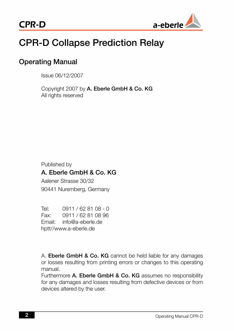
Issue: 06/2008Software Version:
Operating Manual
CPR-D Collapse Prediction RelayDMR-D Damping Monitor
GBOperatingManualCPR-D
CPR-D
CPR-D Collapse Prediction Relay
Operating Manual
Issue06/12/2007
Copyright2007byA. Eberle GmbH & Co. KGAllrightsreserved
Publishedby
A. Eberle GmbH & Co. KGAalenerStrasse30/32
90441Nuremberg,Germany
Tel: 0911/628108-0Fax: 0911/62810896Email: [email protected]//www.a-eberle.de
A. Eberle GmbH & Co. KGcannotbeheldliableforanydamagesor lossesresultingfromprintingerrorsorchangestothisoperatingmanual.FurthermoreA. Eberle GmbH & Co. KGassumesnoresponsibilityforanydamagesandlossesresultingfromdefectivedevicesorfromdevicesalteredbytheuser.
CPR-D
OperatingManualCPR-D
Table of Contents
General ................................................................................................ 6
Use of the CPR-D ............................................................................... 7
3 Functional Principle .......................................................................... 3.1 FingerprintAnalysis....................................................................................... 12
3.1.1 Oscillations..............................................................................................................163.1.2 Torsionaloscillations................................................................................................163.1.3 Low-frequencyoscillations.......................................................................................173.1.4 Downwindtowershadeorwindbarriereffect...........................................................17
3.2 LyapunovExponent...................................................................................... 203.3 DampingMonitor.......................................................................................... 213.4 DriftProcess................................................................................................. 27
4 Presentation of the Different Measurement Quantities ................... 84.1 Averages...................................................................................................... 284.2 AveragesFPA................................................................................................ 294.3 Extremes10ms............................................................................................. 304.4 Extremes10ms5s.......................................................................................... 304.5 MaximaFPA.................................................................................................. 314.6 BinarySignals................................................................................................ 334.7 AmplitudeFFT............................................................................................... 334.8 ComplexFFT................................................................................................. 334.9 DampAvg..................................................................................................... 334.10 DampCnt...................................................................................................... 34
5 Recorder Data ................................................................................... 355.1 ParameterisationoftheRecorders................................................................ 38
5.1.1 Measurementquantities(5s)....................................................................................39
6 CPR-D as a System Component ...................................................... 4
7 Technical Design ............................................................................... 47.1 TheHardware............................................................................................... 42
8 Electrical Data ................................................................................... 438.1 RegulationsandStandards........................................................................... 438.2 ACVoltageInput........................................................................................... 438.3 BinaryInputs(inputsE1...E6)....................................................... 438.4 RelayOutputs(relayR1...R6,statusrelay)...................................... 448.5 AnalogueOutputs(K1,K2).............................................................. 448.6 ReferenceConditions................................................................................... 448.7 ElectricalSafety............................................................................................ 448.8 ElectromagneticCompatibility....................................................................... 458.9 ClimaticStability........................................................................................... 46
OperatingManualCPR-D 3
CPR-D
8.10 PowerSupply............................................................................................... 468.11 Display,Status,Reset................................................................................... 46
9 Mechanical Design ........................................................................... 479.1 Plug-InModule............................................................................................. 479.2 PinAssignment............................................................................................ 489.3 BlockDiagram.............................................................................................. 48
0 Assignment of the Socket Connectors ............................................ 5010.1 SocketConnector1:Voltages..................................................................... 5010.2 SocketConnector4..................................................................................... 5110.3 SocketConnector5..................................................................................... 52
Interfaces .......................................................................................... 5311.1 COM2Interface(RS232,optional)............................................................... 5311.2 COM3Interface(RS485,optional)............................................................... 5311.3 E-LAN(EnergyLocalAreaNetwork)............................................................. 53
Configuration Information ................................................................ 5412.1 TimeSynchronisationandMeasurementTrigger........................................... 5612.2 MeasurementTrigger.................................................................................... 57
3 Parameterisation ............................................................................... 5913.1 WinCP-TheParameterisationandEvaluationSoftware............................... 60
13.1.1 Overview(analyses,records,signals).......................................................................6013.1.2 Callvia„PQStart“.....................................................................................................6013.1.3 „PQPara“–Thresholds,connections,IO...................................................................6113.1.4 „PQPara“–Thresholdsofhalf-period-signals............................................................6113.1.5 Relays+LED(CPParaConf).....................................................................................6213.1.6 Dataclassesinoverview..........................................................................................6213.1.7 Dataclasses-ParameterisationCPR-D.....................................................................6313.1.8 Continuesrecording.................................................................................................6313.1.9 DisturbancerecorderRecA/B/C/D...........................................................................6413.1.10Events/Oscillationevents........................................................................................6413.1.11DisplayinPara-Software..........................................................................................6513.1.12Fingerprint-Analysis(FPA).........................................................................................6513.1.13Stability-Analysis(LyapunovExponent).....................................................................6613.1.14damps-Monitor........................................................................................................6613.1.15Readoutanddisplayofmeasureddata....................................................................6713.1.16Trenddisplayofimportantquantities........................................................................6713.1.17Readoutanddisplayofthemodes...........................................................................6813.1.18Readoutanddisplayofthevalues............................................................................6813.1.19ApossibleITinfrastructure.......................................................................................69
4 Startup ............................................................................................... 7014.1 SafetyInformation......................................................................................... 7014.2 Step-by-StepProcedure............................................................................... 70
5 Applications ...................................................................................... 715.1 Application-SpecificProgramming................................................................ 71
CPR-D
OperatingManualCPR-D4
6 Updating the Firmware ..................................................................... 7
7 Scope of Delivery .............................................................................. 7
8 Maintenance and Electricity Consumption ...................................... 7318.1 FuseReplacement........................................................................................ 7318.2 BatteryReplacement.................................................................................... 7318.3 CPR-DElectricityConsumption.................................................................... 74
9 Storage Information .......................................................................... 75
0 Warranty ............................................................................................ 75
OperatingManualCPR-D 5
CPR-D
1 GeneralIndustrialgrowthislinkeddirectlytothegrowingdemandforelectricalpower.ThisisparticularlyapparentinAsiawithaneconomicgrowthof10%peryear.
BottlenecksarenotrestrictedonlytoAsia,AfricaandAmerica,however,andthenetworksinEuropealsooperateconstantlyatfullcapacityduetolegalframeworkconditions(transferservicesfromEasttoWest).Additionalpowerdemandsorfeedingcapacitiesatthemediumvoltagelevel(e.g.throughwindparks)cancauseacriticaloperatingstatusforthenetworks.
If-duetochangingloaddynamics-thestabilityreservebecomesprogressivelysmaller,excitations(connectionordisconnectionofmajorloads,changeofsup-plyfeed,changeofnetworktopology)arenolongerdampenedsufficientlyandthenetworkmaybecomeunstable,whichisoftenfollowedbyabreakdown,i.e.ablackout.
Theneedtofindtoolstooffsetthissituationwasthestartingpointforthedevel-opmentoftheCPR-DCollapsePredictionRelay.Whathadtobekeptinmindduringtheprocesswasthefactthattheinformationwaslocatedwhereithadnotbeenexpecteduptonow-andhadthereforenotbeenpursued,namelyinthefrequencyrangefromafew10mHzto50Hz.Classicalmeasuringtechnologydealswithvoltages,currents,impedances,outputsandfrequencies.Withregardtofrequencyinparticular,itneedstobenotedthatmeasurementswerenormallyonlydoneinthefrequencyrangeof50/60Hzandhigher.Itwasalwaystheharmonics-the3rd,the5thetc.-andmorerecentlyalsotheintermediateharmonicswhichhadrousedtheinterestsofthemeasuringtechniciansandsystemstheorists.
From the theoriesofnon-lineardynamics,bifurcation theoryanddeterministicchaosincanbederivedthattheconditionofanetworkcanbepermanentlyas-certainedandassessedonthebasisofitsstability.Itisprimarilythe<50Hzfre-quencyrangewhichisusedtodothis.Theassessmentoffrequencies<50Hzopensupthepossibilityofmonitoringcollapseprocesses“generating”significantchangesinthisfrequencyrange.Iftheprocessisslow,thenetworkoperatorcaninitiatesuitablecountermeasuresintimetopreventthenetworkbreakdown.Thismeans that therearenowsuitable toolsfinallyavailablewhichpermit theintroductionofcountermeasuresaheadof,andtherebypreventing,acollapse.Theeconomicbenefitofthisdevelopmentisobvious.Ofcourse,intendedand/orunintendedswitchingoperationscannotbepredictedwiththeCPR-Danymorethannaturaldisasterscanbeforecast.
CPR-D
OperatingManualCPR-D6
2 UseoftheCPR-DTheCPR-DCollapsePredictionRelayisameasuringandmonitoringdevicefortheearlydetectionofblackouts,theidentificationofweakpointsinthenetworkandforobtainingthedataindispensibleforsafenetworkplanning.Thisdataisgainedbycontinuouslycapturingandassessingthedynamicprocessesinthenetwork.
AlthoughthetypedesignationCollapsePredictionRelayindicatestheuseofthedeviceforthepredictionofcollapsesandblackouts,theCPR-Dcanbeusednotonlyfortheearly detection of a blackoutbutalsofortheprevention of large-scale disruptions.Thesignificanceofthisaspectismuchmoreimportantthanthepredictionfunction.
Innormal,everydayoperation,thedampingvaluesalreadyprovideaverygoodoverviewofthedynamicstatusofthenetwork.TheCPR-Dgeneratesadampingfrequencymapfortheinstallationlocationandits“environment”.Thedefinitionof the term“environment” isdifficult in thiscontextbecausetheCPR-Dcanalsodetectso-calledinter-areaoscillationswithglobaleffects.Atanyrate,thisinformationpermitsthecreationofdampingmapswhichrevealtheweak points in the network.
Alertsontheimpactofnetworkchangesandinformationonnetworkresponsesduetoloaddynamicsandstochasticsuppliersinfluencethedampingpropertiesofthenetworkandareindispensableparametersfordynamic network control.
Anotherkeyaspectofdynamicnetworkcontrol isoptimised network utilisa-tion.WiththevariablesgainedfromtheCPR-D,thetransmissioncapacitiescanbecom-binedwiththedynamicprocessesinthenetworkandarethusbetterutilised.Thefact that temperaturemeasurementdevicesare installedonthetransmis-sionsystemsinmanycountriescanbeseenasameaningfulsupplementtotheinformationobtainedfromtheCPR-D.
ThedampingmapsandthestatisticevaluationofthechangeorthedevelopmentoftheLyapunov exponents provideimportantinsights for network planning.
Thisaspectmustbeviewedprimarilyagainstthebackgroundofcurrentchangeprocesses.Theintegrationofregenerativeenergyconverters,tradeactivitiesaswellaselementsthatcanchangetheloadflow-previouslyafixedvariable-con-tributetotheinstabilityofthenetworksandopposetheclassicalview.
Experienceshowsthatmodernnetworkscannotbesafelyoperatedwithclassicaltools.Newtypesoffacilitiesandmeasuringprocessesarerequiredtomatchthesociety'scurrentandparticularlyitsfuturedemands.
OperatingManualCPR-D 7
CPR-D
Thebreakdown(collapse)ofanelectricalenergysupplynetworkcausesmajorfinanciallossesforboththenetworkoperatorandtheconsumer.Therefore,thedetectionofathreatsituationasearlyaspossibleisaprerequisiteforbeingabletotakemeasurestopreventsuchabreakdown.
ThenewCPR-DCollapsePredictionRelayhelpsdetectnetworkbreakdownsattheearliestpossiblestage.Collapsesinelectricalsupplynetworkscanbeexplainedusingthetheoryofnon-lineardynamics,bifurcationtheoryanddeterministicchaos.Themainapplicationforthisdevicetechnologyisinhighvoltageandextra-highvoltagenetworks.Therearevariousmethodsavailablefortheearlyrecognitionofcriticalnetworksituationsandthesecanbeusedsequentially,simultaneouslyorindependentlyofoneanother.
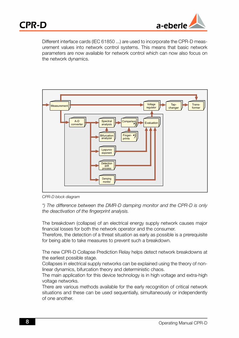
Differentinterfacecards(IEC61850...)areusedtoincorporatetheCPR-Dmeas-urement values into network control systems. Thismeans that basic networkparametersarenowavailablefornetworkcontrolwhichcannowalsofocusonthenetworkdynamics.
CPR-D block diagram
*) The difference between the DMR-D damping monitor and the CPR-D is only the deactivation of the fingerprint analysis.
CPR-D
OperatingManualCPR-D8
Thecombinationwithexternaltap-changerinformationmakethe detectionof“gradualnetworkbreakdowns”usingthe“tap/timemethod” possiblepossible Frequencyrelayfunctions(absolutevalueandgradientofnetwork frequency is detected and analysed)is detected and analysed)isdetectedandanalysed) Measurementoflowfrequenciesandcomparisonwithareference model (((fingerprint) Monitoringofthevoltagedriftprocess Monitoringthe“change”oftheLyapunovexponent Monitoringthedampingprofileofthenetwork
Thecontinualandprecisemeasurementofall frequencieswithinthe0.1to50Hzrangeisaparticularrequirement,inadditiontovoltagemonitoring.Thesefre-quenciesareusedtoevaluatetheloaddynamicsandprovideameasureforthenetwork'sstabilityreserve.TwodifferentFastFourierTransformations(FFTs)coveringthe0.01Hzto124.9Hzrangeareusedtodeterminethefingerprint.
Thestabilityreservecanalsobedefinedbythedistanceofthesystemfromtheso-calledHopfpoint,although itmustberememberedthat thechangeof thedistancefromtheHopfpointisnottheonlyeffectthatcanimpactonasystemwithregardtoitsstabilityreserves.OncetheHopfpointisreached,thenetworkcandevolveintoachaoticcondition.ThistransitionisknownasaHopfbifurcation.ThepositionoftheHopfpointisafunctionoftheloaddynamicsbutitcanalsobeinfluencedbyadditionalparameters.
TheapproachingoftheHopfpointisindicatedbyvariousfrequencyspectra,towhichaspecificgloballoaddynamiccanalwaysbeallocated.Thesespectracanbeactivatedbytorsionalorloadoscillationsortheintermediateoscillationsbetweenelectricalsystems.
TheCPR-Dcanbedeployedatanylocationinanelectricalnetwork.Itonlymeasuresthevoltages.
TheCPR-Dprovidesvariousoutputsignals: AdvancedwarningofanetworkbreakdownWarningofanetworkbreakdown InhibitregulatorActivationofregulatorafteralarmsituation
Everysignalisassignedaspecificparameterrecordusinganautomaticstatusdevice:TriggerconditionResetconditionReactiondelayResetdelay
OperatingManualCPR-D 9
CPR-D
Furthermore,mAsignalsareavailableasanalogueoutputsandcanhaveanymeasurementparametersassignedtothem(e.g.theLyapunovexponent).
ThewayinwhichthemAoutput“Lyapunovexponent”ofthefingerprintanalysisand/ordampingmonitoraltersaftera“networkbreakdownadvancewarning”helpsdecidewhetherthenetworkisstillmovinginthedirectionofacollapse,ifitisstuckinacriticalcondition,orwhetherthenetworkparametersarestabilising.Theactivityguidelinesforpreventingabreakdownarealsoderivedfromthede-velopmentoftheLyapunovexponent.
Thepossibleactionsinclude:LoadsheddingFeedingadditionalactivepowerFeedingadditionalreactivepower IndependentnetworkCombinations
Furthermore,criticalchangestothenetworkarestoredinaneventrecorderto-getherwithinformationregardingtheperiodbeforeandaftertheevent.Pre-triggerandpost-triggertimescanbeselectedindividually.Dependingontheincident,thefaultrecord−canberecordedeitherbasedon0.5ms,10ms,5sor50secondsamplingfrequencyandprovidesoscillographicpicturesofthefault.
Thefaultrecorderscanregisterthefollowingsignals: Samplevaluesofthenetworkvoltage Averagevaluesofthenetworkvoltage Samplevaluesofthenetworkfrequency Averagevalueofthenetworkfrequency Gradientofthenetworkfrequency Binaryinputsignals Binaryoutputsignals
SummaryoftheCPR-DCollapsePredictionRelayfeatures: Spectralanalysiswithhighfrequencyresolutioninthe 0.01Hzto124.9Hzrange Concurrentevaluationoftheharmonic characteristicsandcomparisonwithreferencemodel (fingerprint) Detectionofcollapse-specificfrequencymodes (fingerprintanalysis) Spectralanalysis,independentoflevel Analysisandevaluationofsystemdynamics Determinationofnetworkdampingcoefficient Real-timecalculationofLyapunovexponent Detectionofgradualnetworkbreakdowns
CPR-D
OperatingManualCPR-D0
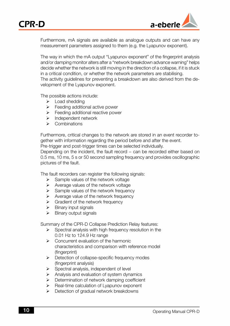
Hardware-oriented block diagram of the Collapse Prediction Relay
Description
Frequencyrelayfunctions(averagevalue,gradient) Standbyfunctionforvoltageregulator Faultrecorderfunctions Differentiatedsignallingstrategiescanberealisedthroughseveralparam-eterisable binary outputsbinary outputsbinaryoutputs
OperatingManualCPR-D
CPR-D
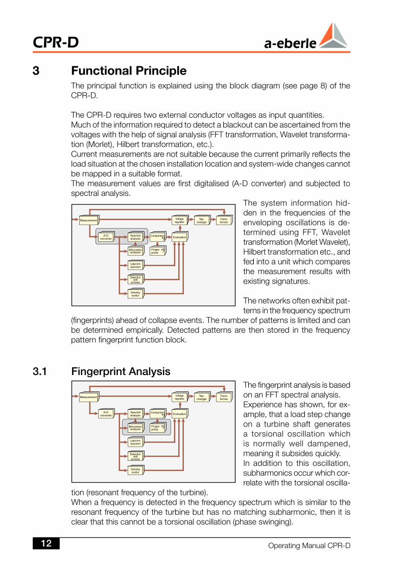
3 FunctionalPrincipleTheprincipalfunctionisexplainedusingtheblockdiagram(seepage8)oftheCPR-D.
TheCPR-Drequirestwoexternalconductorvoltagesasinputquantities.Muchoftheinformationrequiredtodetectablackoutcanbeascertainedfromthevoltageswiththehelpofsignalanalysis(FFTtransformation,Wavelettransforma-tion(Morlet),Hilberttransformation,etc.).Currentmeasurementsarenotsuitablebecausethecurrentprimarilyreflectstheloadsituationatthechoseninstallationlocationandsystem-widechangescannotbemappedinasuitableformat.Themeasurement valuesare firstdigitalised (A-Dconverter) andsubjected tospectralanalysis.
The system information hid-den in the frequencies of theenveloping oscillations is de-termined using FFT, Wavelettransformation(MorletWavelet),Hilberttransformationetc.,andfedintoaunitwhichcomparesthe measurement results withexistingsignatures.
Thenetworksoftenexhibitpat-ternsinthefrequencyspectrum
(fingerprints)aheadofcollapseevents.Thenumberofpatternsislimitedandcanbedeterminedempirically.Detectedpatternsare thenstored in the frequencypatternfingerprintfunctionblock.
3. Fingerprint AnalysisThefingerprintanalysisisbasedonanFFTspectralanalysis.Experiencehasshown,forex-ample,thataloadstepchangeon a turbine shaft generatesa torsional oscillation whichis normally well dampened,meaningitsubsidesquickly.In addition to this oscillation,subharmonicsoccurwhichcor-relatewiththetorsionaloscilla-
tion(resonantfrequencyoftheturbine).Whenafrequencyisdetectedinthefrequencyspectrumwhichissimilartotheresonantfrequencyoftheturbinebuthasnomatchingsubharmonic,thenit isclearthatthiscannotbeatorsionaloscillation(phaseswinging).
CPR-D
OperatingManualCPR-D
OthertypicalfrequencieslieinthemHzrange.Itisalsoknownthatgeneratorssynchroniseor“cluster”inastableinterconnec-tion.This is no longerpossible in heavily loadednetworks as thegeneratorsworkwithdifferentfrequencies.Duetotheintegratedoutputfrequencycontroller,thefrequencyisdirectlyproportionaltotheoutput.Operating thenetwork in theproximityofaHopfbifurcationpointcan lead tofrequencydifferencesbetweenEast,West,NorthandSouth.Theimpressionthatenergyispushedfromonesideofthesupplyareatotheotherfromwhereitflowsbackagainisanappropriatedescriptionofthescenario.Theso-called“inter-areaoscillations”areintherangeofafewmHzandarealsoasignificantindicatorofanetworkwithastabilityreserveapproachingzero.
Thenon-lineardynamicsareallocatedtospecificfrequencyrangesbelow.Anumberofliteraturesourcesinwhichtheauthorshadexamineddifferentphysi-calphenomenawereassessedforthispurpose.Furthermore,theIEEEmodelsinthepublication“SubsynchronousResonanceinPowerSystems”wereevaluatedandusedasresearchbasis.Theobjectiveoftheseeffortswastoestablishacomparisonwithgenericnon-linearmodels.Thedynamicscanbeallocatedtothecausesgeneratingthem.Withsomenon-linearprocessesthefurtherprocessprogressionisdeterminedbythepattern.
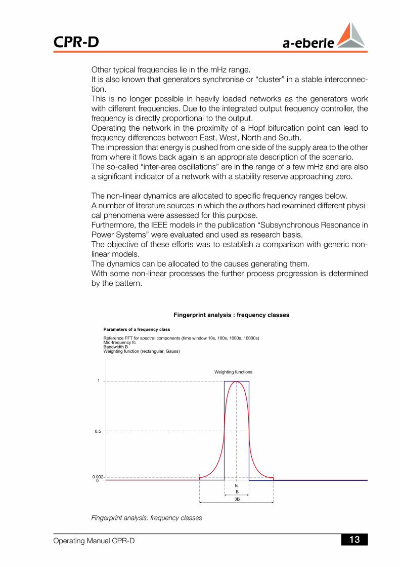
Fingerprint analysis: frequency classes
OperatingManualCPR-D 3
CPR-D
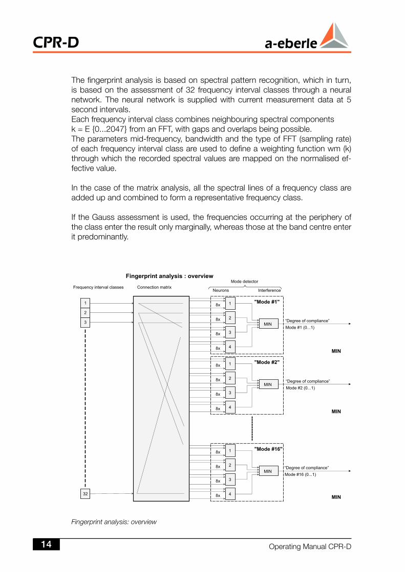
Fingerprint analysis: overview
Thefingerprintanalysisisbasedonspectralpatternrecognition,whichinturn,isbasedontheassessmentof32 frequency intervalclassesthroughaneuralnetwork. Theneural network is suppliedwith currentmeasurementdata at 5secondintervals.Eachfrequencyintervalclasscombinesneighbouringspectralcomponentsk=E0...2047fromanFFT,withgapsandoverlapsbeingpossible.Theparametersmid-frequency,bandwidthandthetypeofFFT(samplingrate)ofeachfrequencyintervalclassareusedtodefineaweightingfunctionwm(k)throughwhichtherecordedspectralvaluesaremappedonthenormalisedef-fectivevalue.
Inthecaseofthematrixanalysis,allthespectrallinesofafrequencyclassareaddedupandcombinedtoformarepresentativefrequencyclass.
IftheGaussassessmentisused,thefrequenciesoccurringattheperipheryoftheclassentertheresultonlymarginally,whereasthoseatthebandcentreenteritpredominantly.
CPR-D
OperatingManualCPR-D4
Differenteventsinthenetworkmodulatethesupplyvoltageenvelopeandcanbedeterminedwithspectralsignalanalysis.Asshownonpage18,typicalfingerprintsdevelopforcertaineventswhichcanbeinterpretedasacombinationofdifferentfrequencies.Tomakesuretherearenofuturerestrictionswiththeallocationofdifferentfrequenciestoafingerprint,theCPR-Dhasbeencreatedwithafeaturepermittinganycombinationoffrequencyintervalclasses.
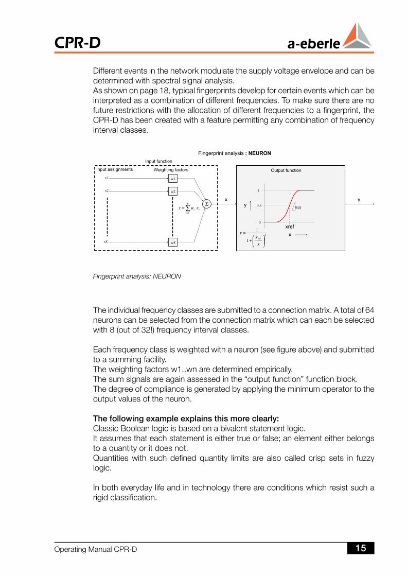
Fingerprint analysis: NEURON
Theindividualfrequencyclassesaresubmittedtoaconnectionmatrix.Atotalof64neuronscanbeselectedfromtheconnectionmatrixwhichcaneachbeselectedwith8(outof32!)frequencyintervalclasses.
Eachfrequencyclassisweightedwithaneuron(seefigureabove)andsubmittedtoasummingfacility.Theweightingfactorsw1..wnaredeterminedempirically.Thesumsignalsareagainassessedinthe“outputfunction”functionblock.Thedegreeofcomplianceisgeneratedbyapplyingtheminimumoperatortotheoutputvaluesoftheneuron.
The following example explains this more clearly:ClassicBooleanlogicisbasedonabivalentstatementlogic.Itassumesthateachstatementiseithertrueorfalse;anelementeitherbelongstoaquantityoritdoesnot.Quantities with such defined quantity limits are also called crisp sets in fuzzylogic.
Inbotheverydaylifeandintechnologythereareconditionswhichresistsucharigidclassification.
OperatingManualCPR-D 5
CPR-D
Mostpeopleperceivearoomtemperatureof0°Cascoldandatemperatureof35°Caswarm.Whataboutatemperatureof18°C,however?Everyoneknowsthat–dependingonthebiorhythmandotherboundaryconditions–18°Ccanappeartobewarmbutalsocold.Infuzzylogic,elementsareallowedtohaveacertainassociation,bothtotheoneandtotheotherquantity.Theassociationisalsoreferredtoasmembershipvalue.Themembershipvalueliesinthevaluerange[0,1].
Thesummationresultofaneuronistreatedanalogicallytotheaboveexample.Theexponents“d”and“Xref”inparticularenabletheincreaseintheoutputfunctiontobedetermined.Thegreater“d”is,thesmallerthetransitionrangebecomes,thesmallerXrefis,thesmallerthefuzzyrange.
Inthetransitionrange,ataspecificpercentagetherespectivexbelongstotheoneandtotheotherquantity.
Basedoncurrentknowledge,moreneuroninputsareavailablethanrequired.Theoutputvaluesofneuronsthatarenotusedmustthereforebesetto“1”.Accordingtotheequationfortheoutputfunction,ybecomes1ifXrefbecomes0.
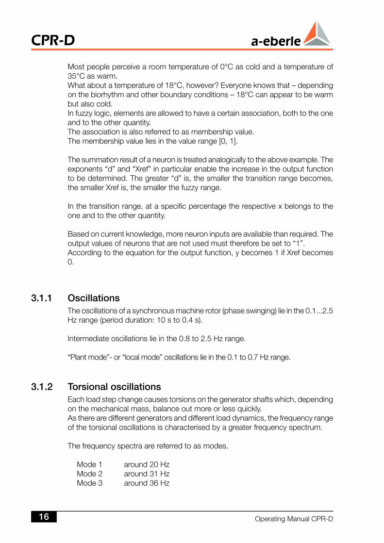
3.. OscillationsTheoscillationsofasynchronousmachinerotor(phaseswinging)lieinthe0.1...2.5Hzrange(periodduration:10sto0.4s).
Intermediateoscillationslieinthe0.8to2.5Hzrange.
“Plantmode”-or“localmode”oscillationslieinthe0.1to0.7Hzrange.
3.. Torsional oscillationsEachloadstepchangecausestorsionsonthegeneratorshaftswhich,dependingonthemechanicalmass,balanceoutmoreorlessquickly.Astherearedifferentgeneratorsanddifferentloaddynamics,thefrequencyrangeofthetorsionaloscillationsischaracterisedbyagreaterfrequencyspectrum.
Thefrequencyspectraarereferredtoasmodes.
Mode1 around20HzMode2 around31HzMode3 around36Hz
CPR-D
OperatingManualCPR-D6
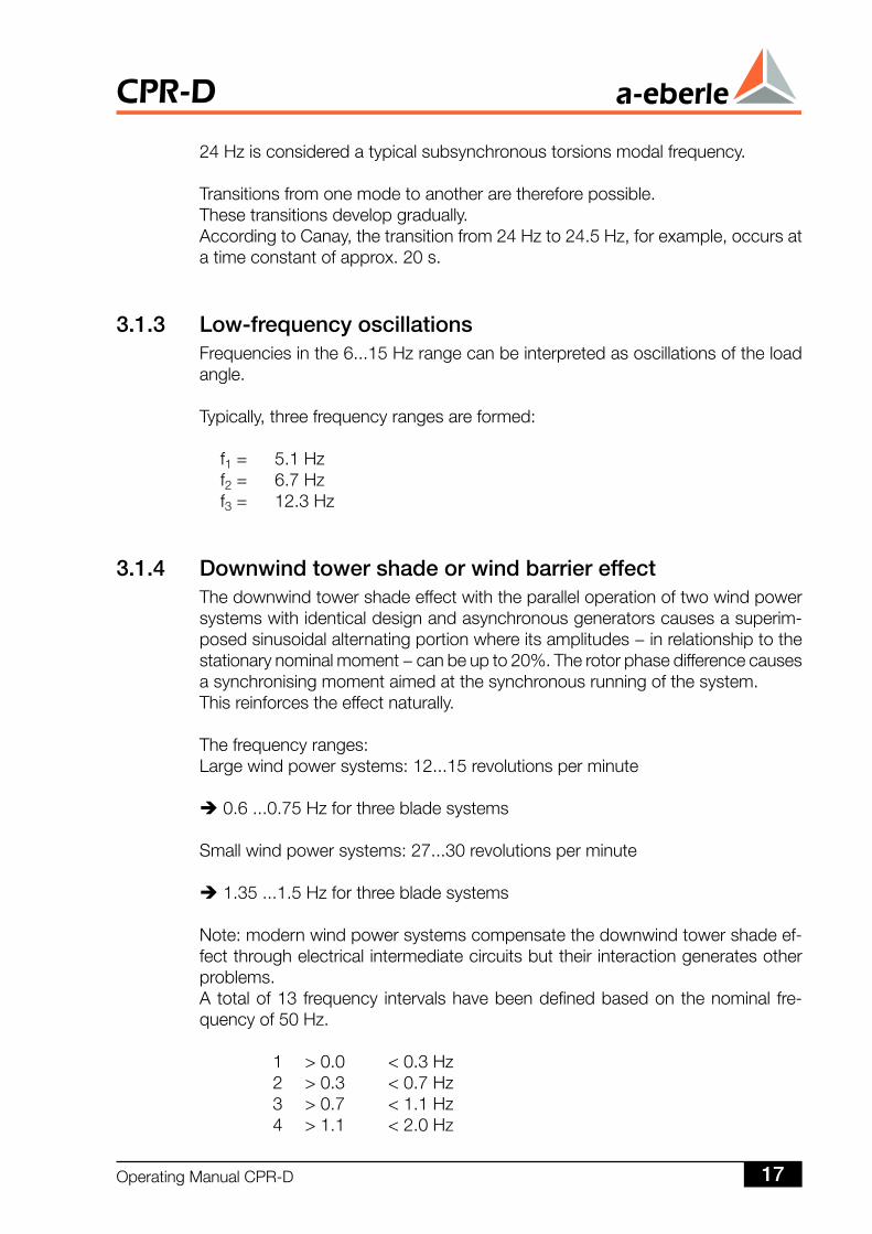
24Hzisconsideredatypicalsubsynchronoustorsionsmodalfrequency.
Transitionsfromonemodetoanotherarethereforepossible.Thesetransitionsdevelopgradually.AccordingtoCanay,thetransitionfrom24Hzto24.5Hz,forexample,occursatatimeconstantofapprox.20s.
3..3 Low-frequency oscillationsFrequenciesinthe6...15Hzrangecanbeinterpretedasoscillationsoftheloadangle.
Typically,threefrequencyrangesareformed:
f1= 5.1Hzf2= 6.7Hzf3= 12.3Hz
3..4 Downwind tower shade or wind barrier effectThedownwindtowershadeeffectwiththeparalleloperationoftwowindpowersystemswithidenticaldesignandasynchronousgeneratorscausesasuperim-posedsinusoidalalternatingportionwhereitsamplitudes−inrelationshiptothestationarynominalmoment−canbeupto20%.Therotorphasedifferencecausesasynchronisingmomentaimedatthesynchronousrunningofthesystem.Thisreinforcestheeffectnaturally.
Thefrequencyranges:Largewindpowersystems:12...15revolutionsperminute
0.6...0.75Hzforthreebladesystems
Smallwindpowersystems:27...30revolutionsperminute
1.35...1.5Hzforthreebladesystems
Note:modernwindpowersystemscompensatethedownwindtowershadeef-fectthroughelectricalintermediatecircuitsbuttheirinteractiongeneratesotherproblems.Atotalof13frequency intervalshavebeendefinedbasedonthenominal fre-quencyof50Hz.
1 >0.0 <0.3Hz 2 >0.3 <0.7Hz 3 >0.7 <1.1Hz 4 >1.1 <2.0Hz
OperatingManualCPR-D 7
CPR-D
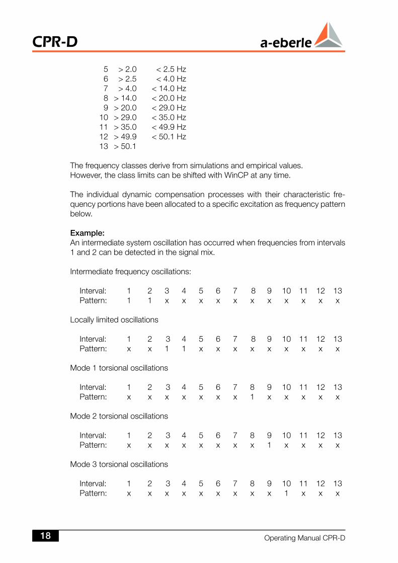
5 >2.0 <2.5Hz 6 >2.5 <4.0Hz 7 >4.0 <14.0Hz 8 >14.0 <20.0Hz 9 >20.0 <29.0Hz 10 >29.0 <35.0Hz 11 >35.0 <49.9Hz 12 >49.9 <50.1Hz 13 >50.1
Thefrequencyclassesderivefromsimulationsandempiricalvalues.However,theclasslimitscanbeshiftedwithWinCPatanytime.
The individual dynamic compensation processes with their characteristic fre-quencyportionshavebeenallocatedtoaspecificexcitationasfrequencypatternbelow.
Example: Anintermediatesystemoscillationhasoccurredwhenfrequenciesfromintervals1and2canbedetectedinthesignalmix.
Intermediatefrequencyoscillations:
Interval: 1 2 3 4 5 6 7 8 9 10 11 12 13Pattern: 1 1 x x x x x x x x x x x
Locallylimitedoscillations
Interval: 1 2 3 4 5 6 7 8 9 10 11 12 13Pattern: x x 1 1 x x x x x x x x x
Mode1torsionaloscillations
Interval: 1 2 3 4 5 6 7 8 9 10 11 12 13Pattern: x x x x x x x 1 x x x x x
Mode2torsionaloscillations
Interval: 1 2 3 4 5 6 7 8 9 10 11 12 13Pattern: x x x x x x x x 1 x x x x
Mode3torsionaloscillations
Interval: 1 2 3 4 5 6 7 8 9 10 11 12 13Pattern: x x x x x x x x x 1 x x x
CPR-D
OperatingManualCPR-D8
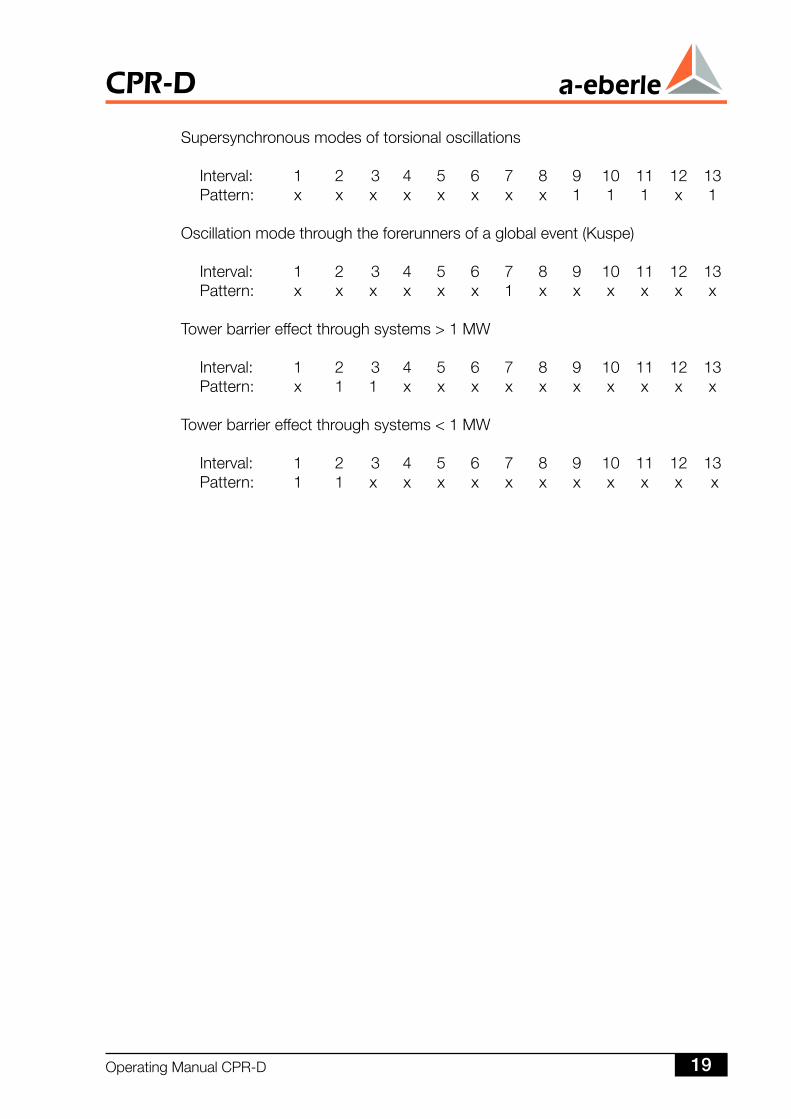
Supersynchronousmodesoftorsionaloscillations
Interval: 1 2 3 4 5 6 7 8 9 10 11 12 13Pattern: x x x x x x x x 1 1 1 x 1
Oscillationmodethroughtheforerunnersofaglobalevent(Kuspe)
Interval: 1 2 3 4 5 6 7 8 9 10 11 12 13Pattern: x x x x x x 1 x x x x x x
Towerbarriereffectthroughsystems>1MW
Interval: 1 2 3 4 5 6 7 8 9 10 11 12 13Pattern: x 1 1 x x x x x x x x x x
Towerbarriereffectthroughsystems<1MW
Interval: 1 2 3 4 5 6 7 8 9 10 11 12 13Pattern: 1 1 x x x x x x x x x x x
OperatingManualCPR-D 9
CPR-D
Anessentialconditionforacollapsepredictionhasbeenmetonceanarchivedfingerprintisdetected.
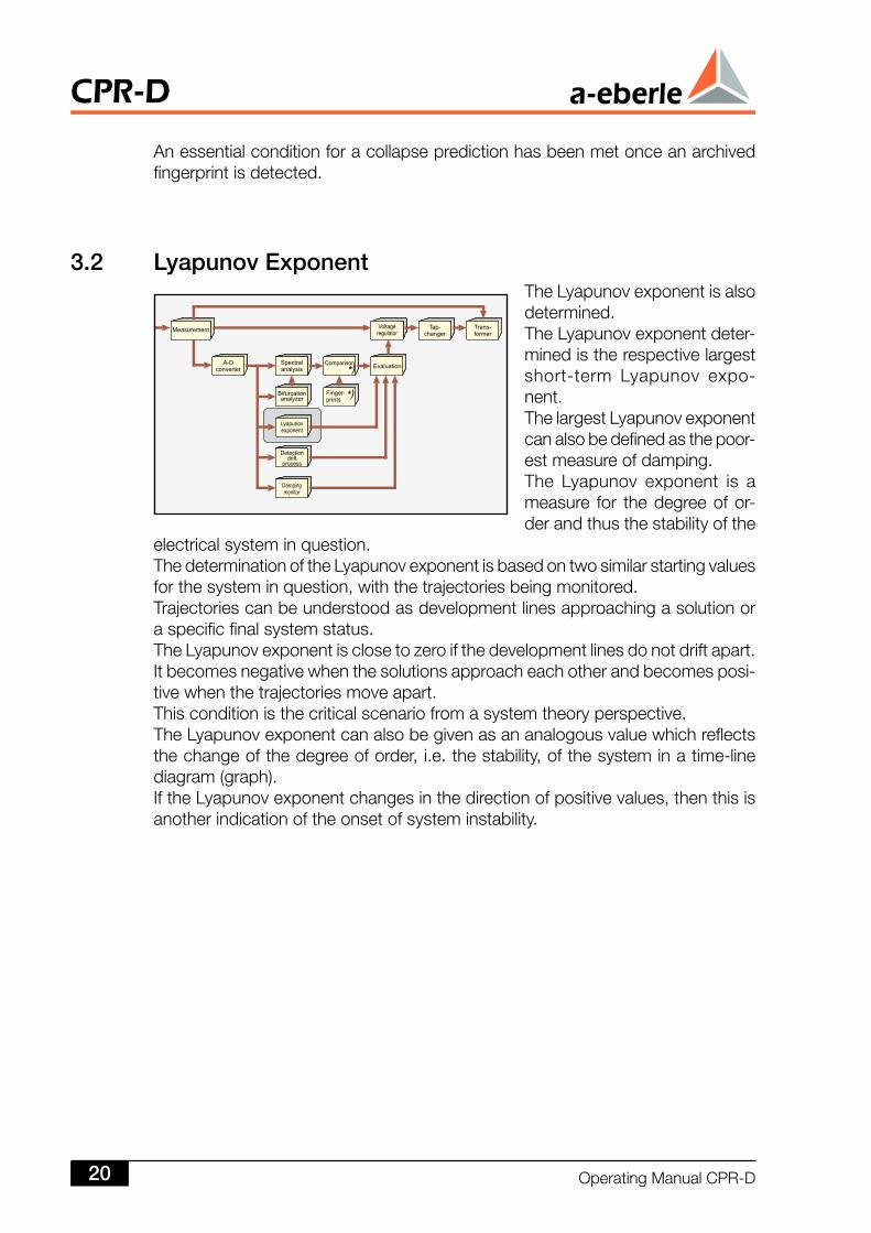
3. Lyapunov ExponentTheLyapunovexponentisalsodetermined.TheLyapunovexponentdeter-minedistherespectivelargestshort-term Lyapunov expo-nent.ThelargestLyapunovexponentcanalsobedefinedasthepoor-estmeasureofdamping.The Lyapunov exponent is ameasure for thedegreeofor-derandthusthestabilityofthe
electricalsysteminquestion.ThedeterminationoftheLyapunovexponentisbasedontwosimilarstartingvaluesforthesysteminquestion,withthetrajectoriesbeingmonitored.Trajectoriescanbeunderstoodasdevelopmentlinesapproachingasolutionoraspecificfinalsystemstatus.TheLyapunovexponentisclosetozeroifthedevelopmentlinesdonotdriftapart.Itbecomesnegativewhenthesolutionsapproacheachotherandbecomesposi-tivewhenthetrajectoriesmoveapart.Thisconditionisthecriticalscenariofromasystemtheoryperspective.TheLyapunovexponentcanalsobegivenasananalogousvaluewhichreflectsthechangeofthedegreeoforder,i.e.thestability,ofthesysteminatime-linediagram(graph).IftheLyapunovexponentchangesinthedirectionofpositivevalues,thenthisisanotherindicationoftheonsetofsysteminstability.
CPR-D
OperatingManualCPR-D0
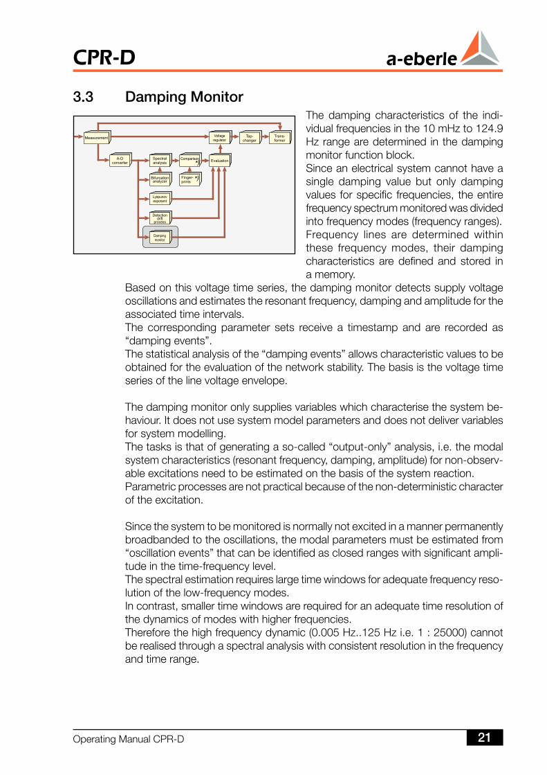
3.3 Damping MonitorThe damping characteristics of the indi-vidualfrequenciesinthe10mHzto124.9Hzrangearedeterminedinthedampingmonitorfunctionblock.Sinceanelectricalsystemcannothaveasingle damping value but only dampingvaluesforspecific frequencies, theentirefrequencyspectrummonitoredwasdividedintofrequencymodes(frequencyranges).Frequency lines are determined withinthese frequency modes, their dampingcharacteristics aredefinedand stored inamemory.
Basedonthisvoltagetimeseries,thedampingmonitordetectssupplyvoltageoscillationsandestimatestheresonantfrequency,dampingandamplitudefortheassociatedtimeintervals.The corresponding parameter sets receive a timestamp and are recorded as“dampingevents”.Thestatisticalanalysisofthe“dampingevents”allowscharacteristicvaluestobeobtainedfortheevaluationofthenetworkstability.Thebasisisthevoltagetimeseriesofthelinevoltageenvelope.
Thedampingmonitoronlysuppliesvariableswhichcharacterisethesystembe-haviour.Itdoesnotusesystemmodelparametersanddoesnotdelivervariablesforsystemmodelling.Thetasksisthatofgeneratingaso-called“output-only”analysis,i.e.themodalsystemcharacteristics(resonantfrequency,damping,amplitude)fornon-observ-ableexcitationsneedtobeestimatedonthebasisofthesystemreaction.Parametricprocessesarenotpracticalbecauseofthenon-deterministiccharacteroftheexcitation.
Sincethesystemtobemonitoredisnormallynotexcitedinamannerpermanentlybroadbandedtotheoscillations,themodalparametersmustbeestimatedfrom“oscillationevents”thatcanbeidentifiedasclosedrangeswithsignificantampli-tudeinthetime-frequencylevel.Thespectralestimationrequireslargetimewindowsforadequatefrequencyreso-lutionofthelow-frequencymodes.Incontrast,smallertimewindowsarerequiredforanadequatetimeresolutionofthedynamicsofmodeswithhigherfrequencies.Thereforethehighfrequencydynamic(0.005Hz..125Hzi.e.1:25000)cannotberealisedthroughaspectralanalysiswithconsistentresolutioninthefrequencyandtimerange.
OperatingManualCPR-D
CPR-D
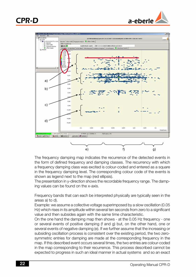
Thefrequencydampingmapindicatestherecurrenceofthedetectedeventsintheformofdefinedfrequencyanddampingclasses.Therecurrencywithwhichafrequencydampingclasswasexcitediscolour-codedandenteredasasquareinthefrequencydampinglevel.Thecorrespondingcolourcodeoftheeventsisshownaslegendnexttothemap(redellipsis).Thepresentationiny-directionshowstherecordablefrequencyrange.Thedamp-ingvaluescanbefoundonthex-axis.
Frequencybandsthatcaneachbeinterpretedphysicallyaretypicallyseenintheareasa)tod).Example:weassumeacollectivevoltagesuperimposedbyaslowoscillation(0.05Hz)whichrisesinitsamplitudewithinseveraltensecondsfromzerotoasignificantvalueandthensubsidesagainwiththesametimecharacteristic.Ontheonehandthedampingmapthenshows-atthe0.05Hzfrequency-oneorseveraleventsofpositivedamping(fandg)but,ontheotherhand,oneorseveraleventsofnegativedamping(e).Ifwefurtherassumethattheincreasingorsubsidingoscillationprocessisconsistentovertheexistingperiod,thetwozero-symmetricentriesfordampingaremadeatthecorrespondingfrequencyinthemap.Ifthisdescribedeventoccursseveraltimes,thetwoentriesarecolour-codedinthemapcorrespondingtotheirrecurrence.Thisprocessdescribedcannotbeexpectedtoprogressinsuchanidealmannerinactualsystemsandsoanexact
CPR-D
OperatingManualCPR-D
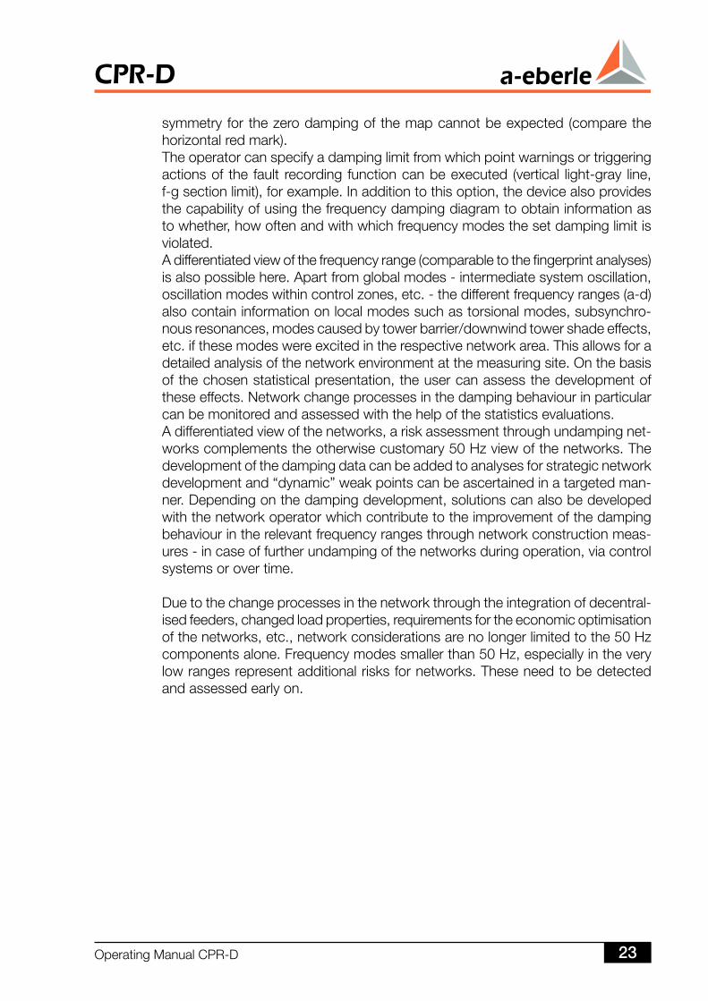
symmetryforthezerodampingofthemapcannotbeexpected(comparethehorizontalredmark).Theoperatorcanspecifyadampinglimitfromwhichpointwarningsortriggeringactionsof the fault recording functioncanbeexecuted (vertical light-gray line,f-gsectionlimit),forexample.Inadditiontothisoption,thedevicealsoprovidesthecapabilityofusingthefrequencydampingdiagramtoobtaininformationastowhether,howoftenandwithwhichfrequencymodesthesetdampinglimitisviolated.Adifferentiatedviewofthefrequencyrange(comparabletothefingerprintanalyses)isalsopossiblehere.Apartfromglobalmodes-intermediatesystemoscillation,oscillationmodeswithincontrolzones,etc.-thedifferentfrequencyranges(a-d)alsocontaininformationonlocalmodessuchastorsionalmodes,subsynchro-nousresonances,modescausedbytowerbarrier/downwindtowershadeeffects,etc.ifthesemodeswereexcitedintherespectivenetworkarea.Thisallowsforadetailedanalysisofthenetworkenvironmentatthemeasuringsite.Onthebasisofthechosenstatisticalpresentation,theusercanassessthedevelopmentoftheseeffects.Networkchangeprocessesinthedampingbehaviourinparticularcanbemonitoredandassessedwiththehelpofthestatisticsevaluations.Adifferentiatedviewofthenetworks,ariskassessmentthroughundampingnet-workscomplementstheotherwisecustomary50Hzviewofthenetworks.Thedevelopmentofthedampingdatacanbeaddedtoanalysesforstrategicnetworkdevelopmentand“dynamic”weakpointscanbeascertainedinatargetedman-ner.Dependingonthedampingdevelopment,solutionscanalsobedevelopedwiththenetworkoperatorwhichcontributetotheimprovementofthedampingbehaviourintherelevantfrequencyrangesthroughnetworkconstructionmeas-ures-incaseoffurtherundampingofthenetworksduringoperation,viacontrolsystemsorovertime.
Duetothechangeprocessesinthenetworkthroughtheintegrationofdecentral-isedfeeders,changedloadproperties,requirementsfortheeconomicoptimisationofthenetworks,etc.,networkconsiderationsarenolongerlimitedtothe50Hzcomponentsalone.Frequencymodessmallerthan50Hz,especiallyintheverylowrangesrepresentadditionalrisksfornetworks.Theseneedtobedetectedandassessedearlyon.
OperatingManualCPR-D 3
CPR-D
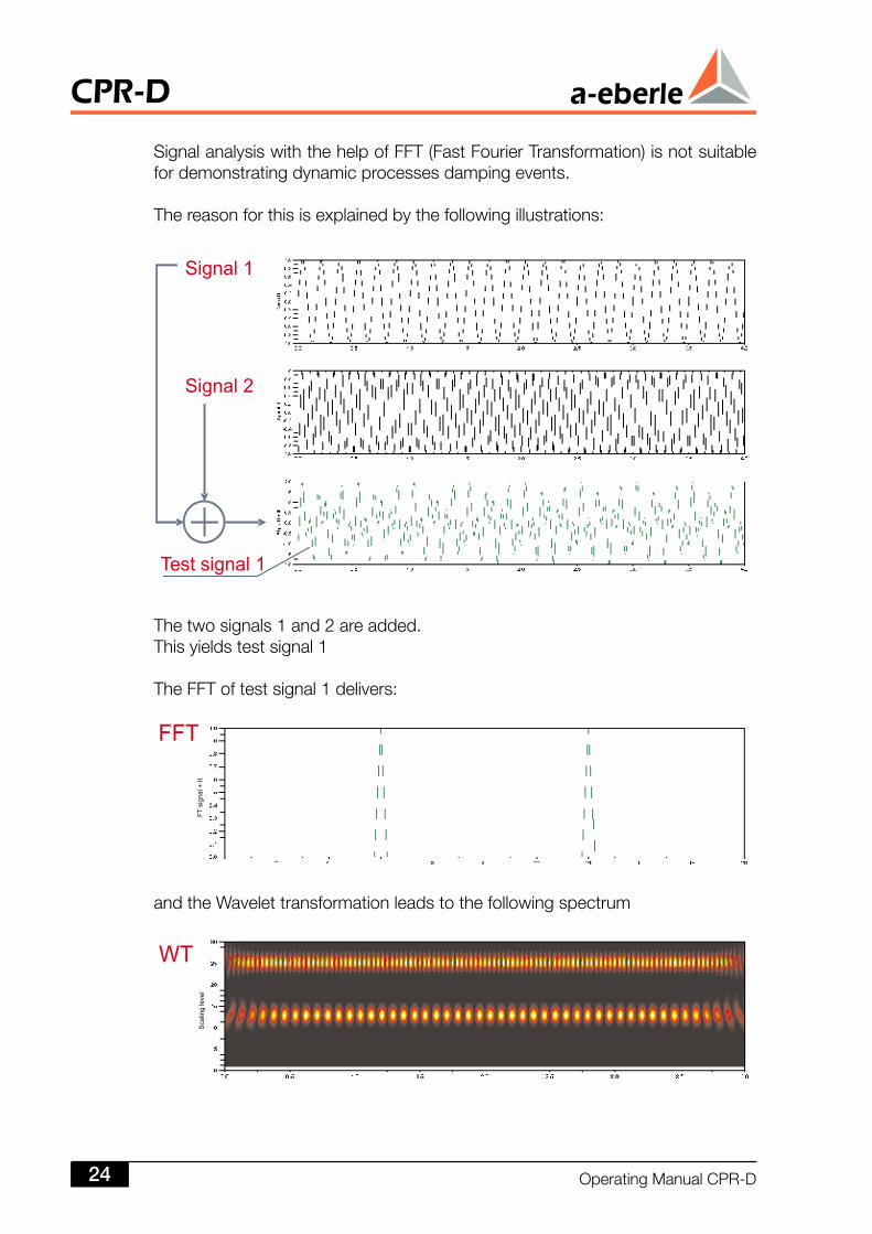
SignalanalysiswiththehelpofFFT(FastFourierTransformation)isnotsuitablefordemonstratingdynamicprocessesdampingevents.
Thereasonforthisisexplainedbythefollowingillustrations:
Thetwosignals1and2areadded.Thisyieldstestsignal1
TheFFToftestsignal1delivers:
andtheWavelettransformationleadstothefollowingspectrum
CPR-D
OperatingManualCPR-D4
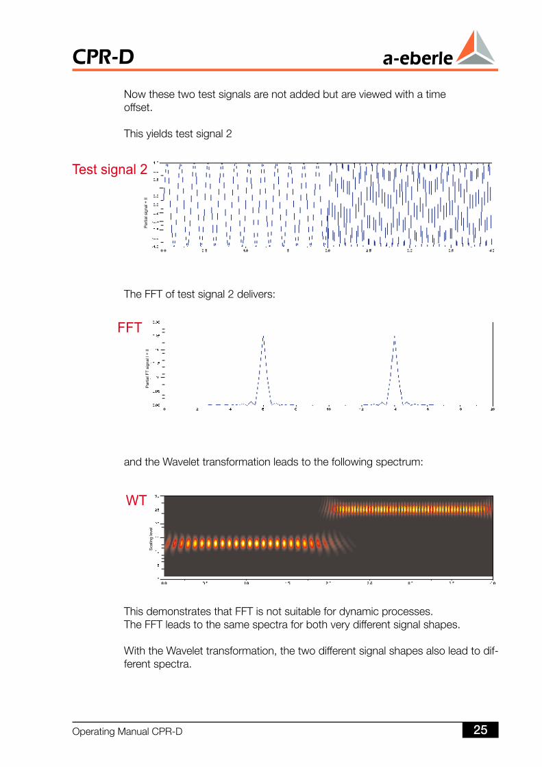
Nowthesetwotestsignalsarenotaddedbutareviewedwithatimeoffset.
Thisyieldstestsignal2
TheFFToftestsignal2delivers:
andtheWavelettransformationleadstothefollowingspectrum:
ThisdemonstratesthatFFTisnotsuitablefordynamicprocesses.TheFFTleadstothesamespectraforbothverydifferentsignalshapes.
WiththeWavelettransformation,thetwodifferentsignalshapesalsoleadtodif-ferentspectra.
OperatingManualCPR-D 5
CPR-D
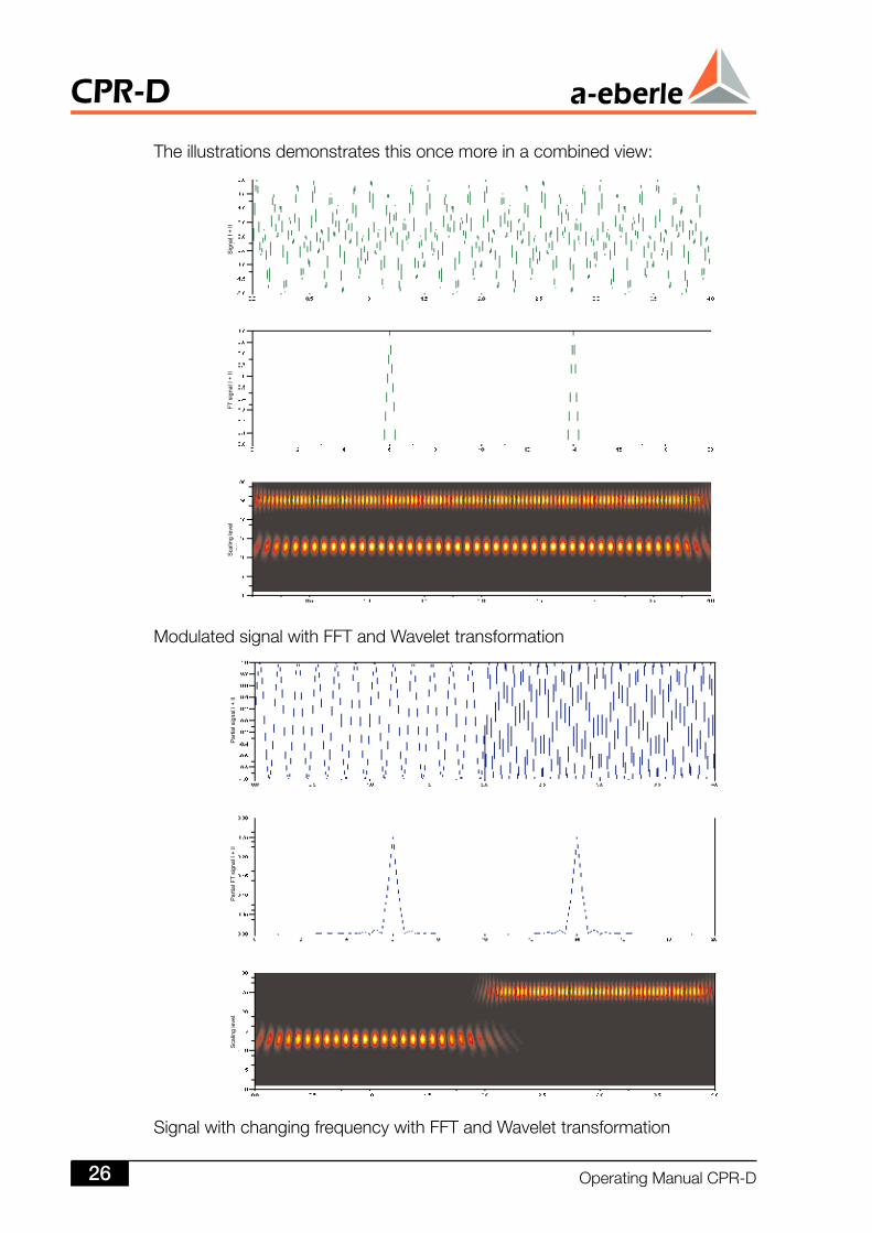
SignalwithchangingfrequencywithFFTandWavelettransformation
Theillustrationsdemonstratesthisoncemoreinacombinedview:
ModulatedsignalwithFFTandWavelettransformation
CPR-D
OperatingManualCPR-D6
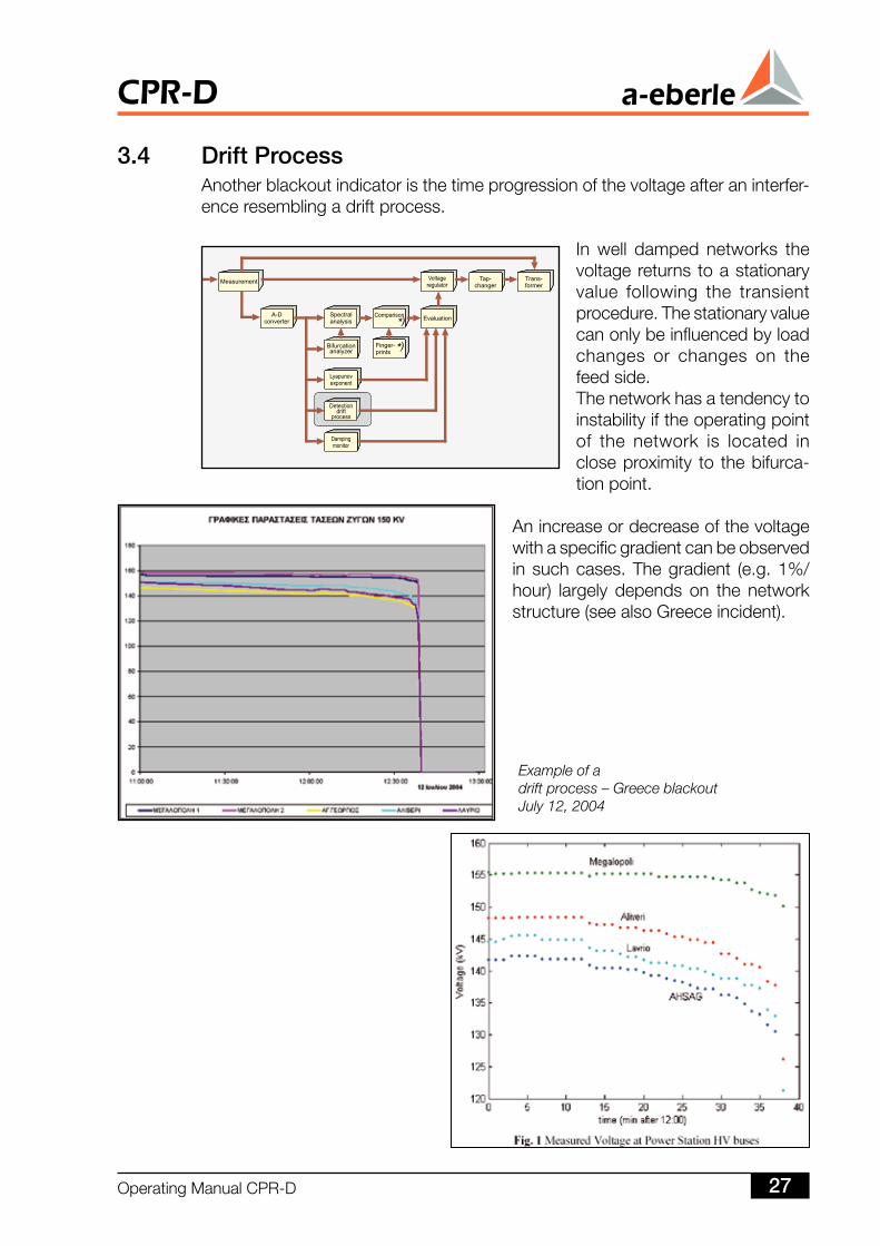
Example of adrift process – Greece blackoutJuly 12, 2004
3.4 Drift ProcessAnotherblackoutindicatoristhetimeprogressionofthevoltageafteraninterfer-enceresemblingadriftprocess.
In well damped networks thevoltagereturnstoastationaryvalue following the transientprocedure.Thestationaryvaluecanonlybeinfluencedbyloadchanges or changes on thefeedside.Thenetworkhasatendencytoinstabilityiftheoperatingpointof the network is located incloseproximity to thebifurca-tionpoint.
Anincreaseordecreaseofthevoltagewithaspecificgradientcanbeobservedinsuchcases.Thegradient (e.g.1%/hour) largely depends on the networkstructure(seealsoGreeceincident).
OperatingManualCPR-D 7
CPR-D
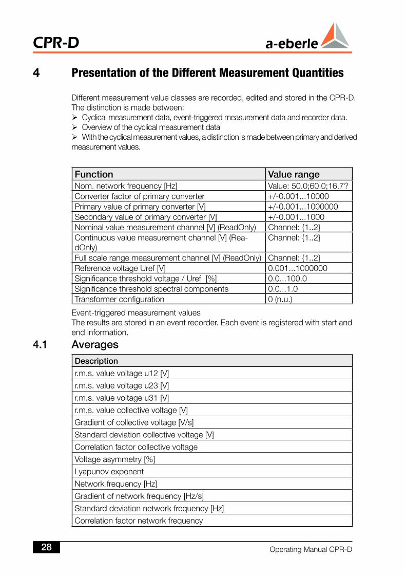
4 Presentation of the Different Measurement Quantities
Differentmeasurementvalueclassesarerecorded,editedandstoredintheCPR-D.Thedistinctionismadebetween: Cyclicalmeasurementdata,event-triggeredmeasurementdataandrecorderdata. Overviewofthecyclicalmeasurementdata Withthecyclicalmeasurementvalues,adistinctionismadebetweenprimaryandderivedmeasurementvalues.
Function Value rangeNom.networkfrequency[Hz] Value:50.0;60.0;16.7?Converterfactorofprimaryconverter +/-0.001...10000Primaryvalueofprimaryconverter[V] +/-0.001...1000000Secondaryvalueofprimaryconverter[V] +/-0.001...1000Nominalvaluemeasurementchannel[V](ReadOnly) Channel:1..2Continuousvaluemeasurementchannel[V](Rea-dOnly)
Channel:1..2
Fullscalerangemeasurementchannel[V](ReadOnly) Channel:1..2ReferencevoltageUref[V] 0.001...1000000Significancethresholdvoltage/Uref[%] 0.0...100.0Significancethresholdspectralcomponents 0.0...1.0Transformerconfiguration 0(n.u.)
Event-triggeredmeasurementvaluesTheresultsarestoredinaneventrecorder.Eacheventisregisteredwithstartandendinformation.
4. AveragesDescription
r.m.s.valuevoltageu12[V]
r.m.s.valuevoltageu23[V]
r.m.s.valuevoltageu31[V]
r.m.s.valuecollectivevoltage[V]
Gradientofcollectivevoltage[V/s]
Standarddeviationcollectivevoltage[V]
Correlationfactorcollectivevoltage
Voltageasymmetry[%]
Lyapunovexponent
Networkfrequency[Hz]
Gradientofnetworkfrequency[Hz/s]
Standarddeviationnetworkfrequency[Hz]
Correlationfactornetworkfrequency
CPR-D
OperatingManualCPR-D8
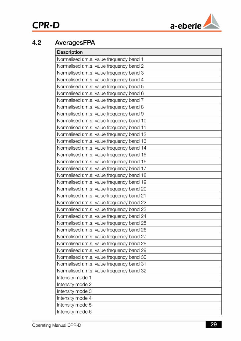
4. AveragesFPADescriptionNormalisedr.m.s.valuefrequencyband1Normalisedr.m.s.valuefrequencyband2Normalisedr.m.s.valuefrequencyband3Normalisedr.m.s.valuefrequencyband4Normalisedr.m.s.valuefrequencyband5Normalisedr.m.s.valuefrequencyband6Normalisedr.m.s.valuefrequencyband7Normalisedr.m.s.valuefrequencyband8Normalisedr.m.s.valuefrequencyband9Normalisedr.m.s.valuefrequencyband10Normalisedr.m.s.valuefrequencyband11Normalisedr.m.s.valuefrequencyband12Normalisedr.m.s.valuefrequencyband13Normalisedr.m.s.valuefrequencyband14Normalisedr.m.s.valuefrequencyband15Normalisedr.m.s.valuefrequencyband16Normalisedr.m.s.valuefrequencyband17Normalisedr.m.s.valuefrequencyband18Normalisedr.m.s.valuefrequencyband19Normalisedr.m.s.valuefrequencyband20Normalisedr.m.s.valuefrequencyband21Normalisedr.m.s.valuefrequencyband22Normalisedr.m.s.valuefrequencyband23Normalisedr.m.s.valuefrequencyband24Normalisedr.m.s.valuefrequencyband25Normalisedr.m.s.valuefrequencyband26Normalisedr.m.s.valuefrequencyband27Normalisedr.m.s.valuefrequencyband28Normalisedr.m.s.valuefrequencyband29Normalisedr.m.s.valuefrequencyband30Normalisedr.m.s.valuefrequencyband31Normalisedr.m.s.valuefrequencyband32Intensitymode1Intensitymode2Intensitymode3Intensitymode4Intensitymode5Intensitymode6
OperatingManualCPR-D 9
CPR-D
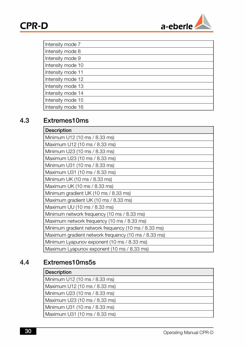
Intensitymode7Intensitymode8Intensitymode9Intensitymode10Intensitymode11Intensitymode12Intensitymode13Intensitymode14Intensitymode15Intensitymode16
4.3 Extremes0msDescriptionMinimumU12(10ms/8.33ms)MaximumU12(10ms/8.33ms)MinimumU23(10ms/8.33ms)MaximumU23(10ms/8.33ms)MinimumU31(10ms/8.33ms)MaximumU31(10ms/8.33ms)MinimumUK(10ms/8.33ms)MaximumUK(10ms/8.33ms)MinimumgradientUK(10ms/8.33ms)MaximumgradientUK(10ms/8.33ms)MaximumUU(10ms/8.33ms)Minimumnetworkfrequency(10ms/8.33ms)Maximumnetworkfrequency(10ms/8.33ms)Minimumgradientnetworkfrequency(10ms/8.33ms)Maximumgradientnetworkfrequency(10ms/8.33ms)MinimumLyapunovexponent(10ms/8.33ms)MaximumLyapunovexponent(10ms/8.33ms)
4.4 Extremes0ms5sDescriptionMinimumU12(10ms/8.33ms)MaximumU12(10ms/8.33ms)MinimumU23(10ms/8.33ms)MaximumU23(10ms/8.33ms)MinimumU31(10ms/8.33ms)MaximumU31(10ms/8.33ms)
CPR-D
OperatingManualCPR-D30
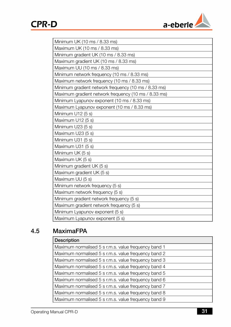
MinimumUK(10ms/8.33ms)MaximumUK(10ms/8.33ms)MinimumgradientUK(10ms/8.33ms)MaximumgradientUK(10ms/8.33ms)MaximumUU(10ms/8.33ms)Minimumnetworkfrequency(10ms/8.33ms)Maximumnetworkfrequency(10ms/8.33ms)Minimumgradientnetworkfrequency(10ms/8.33ms)Maximumgradientnetworkfrequency(10ms/8.33ms)MinimumLyapunovexponent(10ms/8.33ms)MaximumLyapunovexponent(10ms/8.33ms)MinimumU12(5s)MaximumU12(5s)MinimumU23(5s)MaximumU23(5s)MinimumU31(5s)MaximumU31(5s)MinimumUK(5s)MaximumUK(5s)MinimumgradientUK(5s)MaximumgradientUK(5s)MaximumUU(5s)Minimumnetworkfrequency(5s)Maximumnetworkfrequency(5s)Minimumgradientnetworkfrequency(5s)Maximumgradientnetworkfrequency(5s)MinimumLyapunovexponent(5s)MaximumLyapunovexponent(5s)
4.5 MaximaFPADescriptionMaximumnormalised5sr.m.s.valuefrequencyband1Maximumnormalised5sr.m.s.valuefrequencyband2Maximumnormalised5sr.m.s.valuefrequencyband3Maximumnormalised5sr.m.s.valuefrequencyband4Maximumnormalised5sr.m.s.valuefrequencyband5Maximumnormalised5sr.m.s.valuefrequencyband6Maximumnormalised5sr.m.s.valuefrequencyband7Maximumnormalised5sr.m.s.valuefrequencyband8Maximumnormalised5sr.m.s.valuefrequencyband9
OperatingManualCPR-D 3
CPR-D
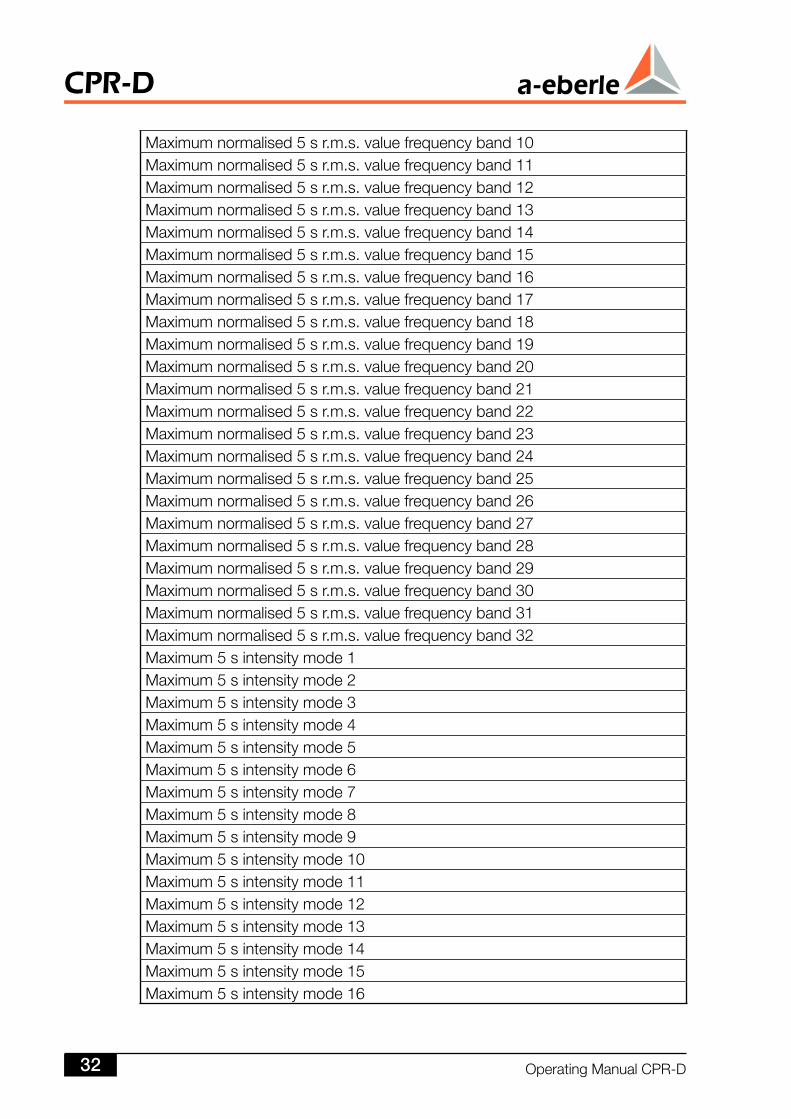
Maximumnormalised5sr.m.s.valuefrequencyband10Maximumnormalised5sr.m.s.valuefrequencyband11Maximumnormalised5sr.m.s.valuefrequencyband12Maximumnormalised5sr.m.s.valuefrequencyband13Maximumnormalised5sr.m.s.valuefrequencyband14Maximumnormalised5sr.m.s.valuefrequencyband15Maximumnormalised5sr.m.s.valuefrequencyband16Maximumnormalised5sr.m.s.valuefrequencyband17Maximumnormalised5sr.m.s.valuefrequencyband18Maximumnormalised5sr.m.s.valuefrequencyband19Maximumnormalised5sr.m.s.valuefrequencyband20Maximumnormalised5sr.m.s.valuefrequencyband21Maximumnormalised5sr.m.s.valuefrequencyband22Maximumnormalised5sr.m.s.valuefrequencyband23Maximumnormalised5sr.m.s.valuefrequencyband24Maximumnormalised5sr.m.s.valuefrequencyband25Maximumnormalised5sr.m.s.valuefrequencyband26Maximumnormalised5sr.m.s.valuefrequencyband27Maximumnormalised5sr.m.s.valuefrequencyband28Maximumnormalised5sr.m.s.valuefrequencyband29Maximumnormalised5sr.m.s.valuefrequencyband30Maximumnormalised5sr.m.s.valuefrequencyband31Maximumnormalised5sr.m.s.valuefrequencyband32Maximum5sintensitymode1Maximum5sintensitymode2Maximum5sintensitymode3Maximum5sintensitymode4Maximum5sintensitymode5Maximum5sintensitymode6Maximum5sintensitymode7Maximum5sintensitymode8Maximum5sintensitymode9Maximum5sintensitymode10Maximum5sintensitymode11Maximum5sintensitymode12Maximum5sintensitymode13Maximum5sintensitymode14Maximum5sintensitymode15Maximum5sintensitymode16
CPR-D
OperatingManualCPR-D3
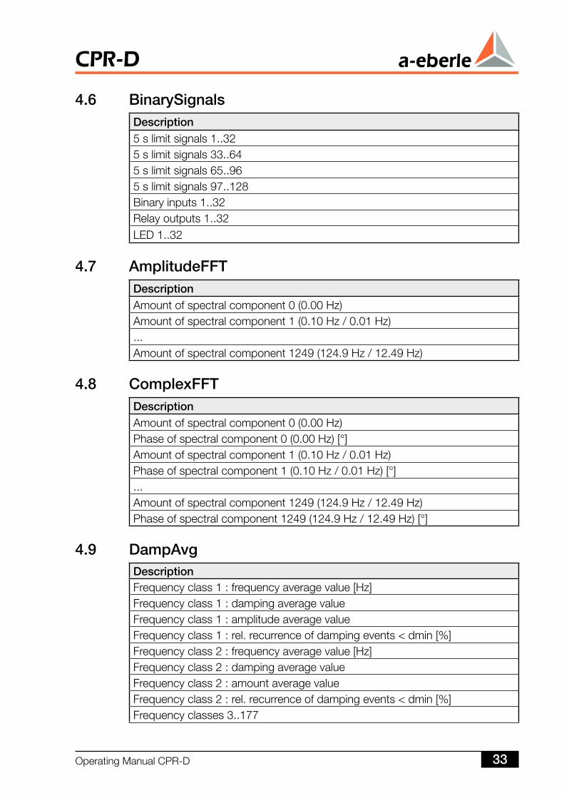
4.6 BinarySignalsDescription5slimitsignals1..325slimitsignals33..645slimitsignals65..965slimitsignals97..128Binaryinputs1..32Relayoutputs1..32LED1..32
4.7 AmplitudeFFTDescriptionAmountofspectralcomponent0(0.00Hz)Amountofspectralcomponent1(0.10Hz/0.01Hz)...Amountofspectralcomponent1249(124.9Hz/12.49Hz)
4.8 ComplexFFTDescriptionAmountofspectralcomponent0(0.00Hz)Phaseofspectralcomponent0(0.00Hz)[°]Amountofspectralcomponent1(0.10Hz/0.01Hz)Phaseofspectralcomponent1(0.10Hz/0.01Hz)[°]...Amountofspectralcomponent1249(124.9Hz/12.49Hz)Phaseofspectralcomponent1249(124.9Hz/12.49Hz)[°]
4.9 DampAvgDescriptionFrequencyclass1:frequencyaveragevalue[Hz]Frequencyclass1:dampingaveragevalueFrequencyclass1:amplitudeaveragevalueFrequencyclass1:rel.recurrenceofdampingevents<dmin[%]Frequencyclass2:frequencyaveragevalue[Hz]Frequencyclass2:dampingaveragevalueFrequencyclass2:amountaveragevalueFrequencyclass2:rel.recurrenceofdampingevents<dmin[%]Frequencyclasses3..177
OperatingManualCPR-D 33
CPR-D
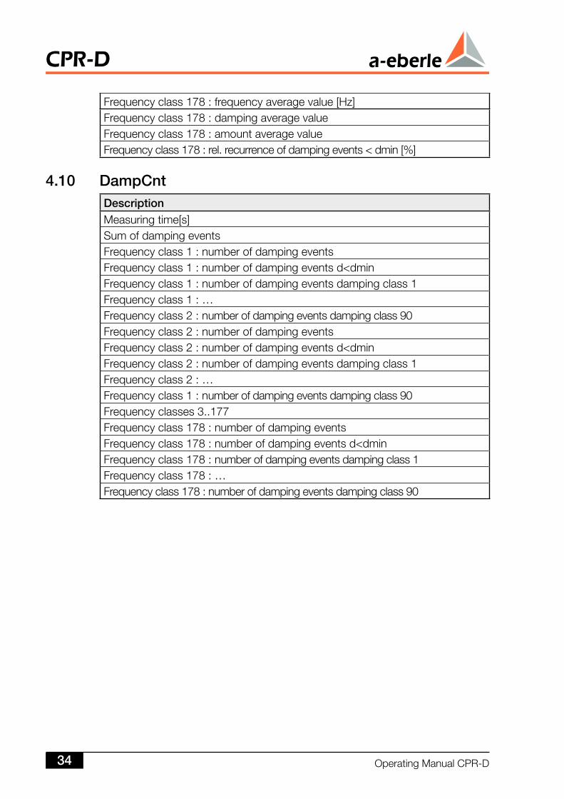
Frequencyclass178:frequencyaveragevalue[Hz]Frequencyclass178:dampingaveragevalueFrequencyclass178:amountaveragevalueFrequencyclass178:rel.recurrenceofdampingevents<dmin[%]
4.0 DampCntDescriptionMeasuringtime[s]SumofdampingeventsFrequencyclass1:numberofdampingeventsFrequencyclass1:numberofdampingeventsd<dminFrequencyclass1:numberofdampingeventsdampingclass1Frequencyclass1:…Frequencyclass2:numberofdampingeventsdampingclass90Frequencyclass2:numberofdampingeventsFrequencyclass2:numberofdampingeventsd<dminFrequencyclass2:numberofdampingeventsdampingclass1Frequencyclass2:…Frequencyclass1:numberofdampingeventsdampingclass90Frequencyclasses3..177Frequencyclass178:numberofdampingeventsFrequencyclass178:numberofdampingeventsd<dminFrequencyclass178:numberofdampingeventsdampingclass1Frequencyclass178:…Frequencyclass178:numberofdampingeventsdampingclass90
CPR-D
OperatingManualCPR-D34
5 RecorderData
TheCPR-Dhasfourrecordersavailable.
Recorder A:ThesamplingratesofthevoltagesarestoredinrecorderA.Thesamplingrateis2048Hzandthereforedeliversfaultrecordsforthevoltagescomparabletothosefromtheprotectivedevices.Thefaultrecordcanberecordedwithaselectablepre-triggerandpost-triggertime.
Recorder B:The10msvaluesfromlimitviolationwith informationbeforeandaftertheeventarestoredinrecorderB.
Recorder C:The50svaluesfromlimitviolationwithinformationbeforeandaftertheeventarestoredinrecorderC.
Recorder D:The5svaluesfromlimitviolationwithinformationbeforeandaftertheeventarestoredinrecorderD.
Eachrecordercanstoreseveralfaultrecordsofequallengthwhicharestoredinchronologicalsequence.Thelengthofthefaultrecordcanbeparameterised.
Therecordersarealsotriggeredthroughbinarysignals.
OperatingManualCPR-D 35
CPR-D
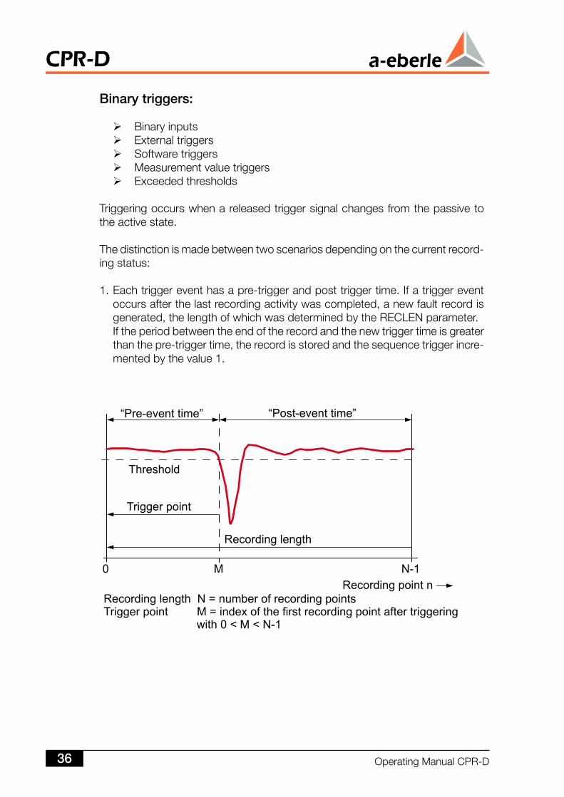
Binary triggers:
Binaryinputs Externaltriggers Softwaretriggers Measurementvaluetriggers Exceededthresholds
Triggeringoccurswhenareleasedtriggersignalchangesfromthepassivetotheactivestate.
Thedistinctionismadebetweentwoscenariosdependingonthecurrentrecord-ingstatus:
1.Eachtriggereventhasapre-triggerandposttriggertime.Ifatriggereventoccursafterthelastrecordingactivitywascompleted,anewfaultrecordisgenerated,thelengthofwhichwasdeterminedbytheRECLENparameter.Iftheperiodbetweentheendoftherecordandthenewtriggertimeisgreaterthanthepre-triggertime,therecordisstoredandthesequencetriggerincre-mentedbythevalue1.
CPR-D
OperatingManualCPR-D36
Thecounterissettozeroifafaultsequenceneedstobeterminatedbecausethemaximumnumberofpermittedfaultrecordshasbeenreached.
TriggersignalsforrecorderARecorderArecordstheeventsonthesamplingvaluelevel.Thesamplingrateis2.048Hz
Measurement quantities:BaseID=832
Description Data typeSamplingvalueu12[V] FloatSamplingvalueu23[V] FloatSamplingvalueu31[V] Float
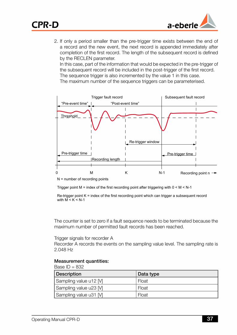
2.Ifonlyaperiodsmaller than thepre-trigger timeexistsbetween theendofarecordandthenewevent,thenextrecord isappendedimmediatelyaftercompletionofthefirstrecord.ThelengthofthesubsequentrecordisdefinedbytheRECLENparameter.Inthiscase,partoftheinformationthatwouldbeexpectedinthepre-triggerofthesubsequentrecordwillbeincludedinthepost-triggerofthefirstrecord.Thesequencetriggerisalsoincrementedbythevalue1inthiscase.Themaximumnumberofthesequencetriggerscanbeparameterised.
OperatingManualCPR-D 37
CPR-D
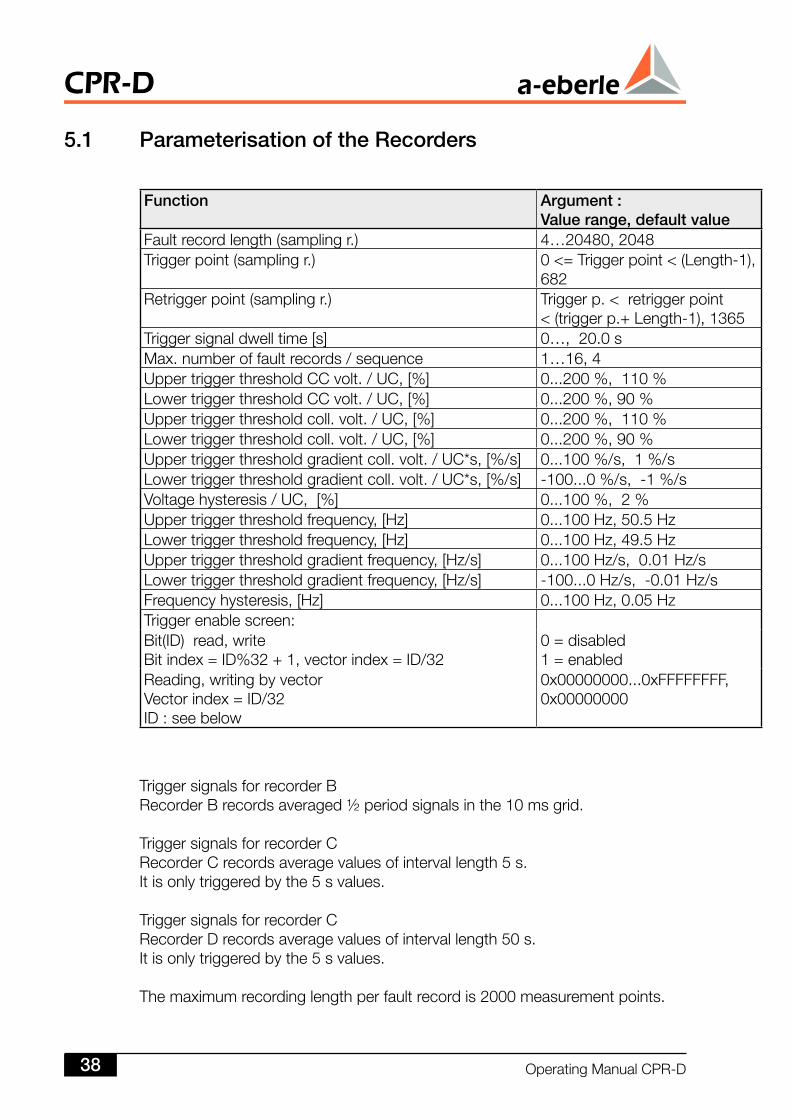
5. Parameterisation of the Recorders
Function Argument :Value range, default value
Faultrecordlength(samplingr.) 4…20480,2048Triggerpoint(samplingr.) 0<=Triggerpoint<(Length-1),
682Retriggerpoint(samplingr.) Triggerp.<retriggerpoint
<(triggerp.+Length-1),1365Triggersignaldwelltime[s] 0…,20.0sMax.numberoffaultrecords/sequence 1…16,4UppertriggerthresholdCCvolt./UC,[%] 0...200%,110%LowertriggerthresholdCCvolt./UC,[%] 0...200%,90%Uppertriggerthresholdcoll.volt./UC,[%] 0...200%,110%Lowertriggerthresholdcoll.volt./UC,[%] 0...200%,90%Uppertriggerthresholdgradientcoll.volt./UC*s,[%/s] 0...100%/s,1%/sLowertriggerthresholdgradientcoll.volt./UC*s,[%/s] -100...0%/s,-1%/sVoltagehysteresis/UC,[%] 0...100%,2%Uppertriggerthresholdfrequency,[Hz] 0...100Hz,50.5HzLowertriggerthresholdfrequency,[Hz] 0...100Hz,49.5HzUppertriggerthresholdgradientfrequency,[Hz/s] 0...100Hz/s,0.01Hz/sLowertriggerthresholdgradientfrequency,[Hz/s] -100...0Hz/s,-0.01Hz/sFrequencyhysteresis,[Hz] 0...100Hz,0.05HzTriggerenablescreen:Bit(ID)read,writeBitindex=ID%32+1,vectorindex=ID/32
0=disabled1=enabled
Reading,writingbyvectorVectorindex=ID/32ID:seebelow
0x00000000...0xFFFFFFFF,0x00000000
TriggersignalsforrecorderBRecorderBrecordsaveraged½periodsignalsinthe10msgrid.
TriggersignalsforrecorderCRecorderCrecordsaveragevaluesofintervallength5s.Itisonlytriggeredbythe5svalues.
TriggersignalsforrecorderCRecorderDrecordsaveragevaluesofintervallength50s.Itisonlytriggeredbythe5svalues.
Themaximumrecordinglengthperfaultrecordis2000measurementpoints.
CPR-D
OperatingManualCPR-D38
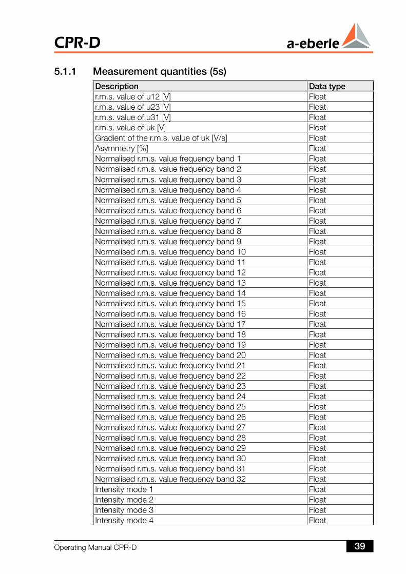
5.. Measurement quantities (5s)Description Data typer.m.s.valueofu12[V] Floatr.m.s.valueofu23[V] Floatr.m.s.valueofu31[V] Floatr.m.s.valueofuk[V] FloatGradientofther.m.s.valueofuk[V/s] FloatAsymmetry[%] FloatNormalisedr.m.s.valuefrequencyband1 FloatNormalisedr.m.s.valuefrequencyband2 FloatNormalisedr.m.s.valuefrequencyband3 FloatNormalisedr.m.s.valuefrequencyband4 FloatNormalisedr.m.s.valuefrequencyband5 FloatNormalisedr.m.s.valuefrequencyband6 FloatNormalisedr.m.s.valuefrequencyband7 FloatNormalisedr.m.s.valuefrequencyband8 FloatNormalisedr.m.s.valuefrequencyband9 FloatNormalisedr.m.s.valuefrequencyband10 FloatNormalisedr.m.s.valuefrequencyband11 FloatNormalisedr.m.s.valuefrequencyband12 FloatNormalisedr.m.s.valuefrequencyband13 FloatNormalisedr.m.s.valuefrequencyband14 FloatNormalisedr.m.s.valuefrequencyband15 FloatNormalisedr.m.s.valuefrequencyband16 FloatNormalisedr.m.s.valuefrequencyband17 FloatNormalisedr.m.s.valuefrequencyband18 FloatNormalisedr.m.s.valuefrequencyband19 FloatNormalisedr.m.s.valuefrequencyband20 FloatNormalisedr.m.s.valuefrequencyband21 FloatNormalisedr.m.s.valuefrequencyband22 FloatNormalisedr.m.s.valuefrequencyband23 FloatNormalisedr.m.s.valuefrequencyband24 FloatNormalisedr.m.s.valuefrequencyband25 FloatNormalisedr.m.s.valuefrequencyband26 FloatNormalisedr.m.s.valuefrequencyband27 FloatNormalisedr.m.s.valuefrequencyband28 FloatNormalisedr.m.s.valuefrequencyband29 FloatNormalisedr.m.s.valuefrequencyband30 FloatNormalisedr.m.s.valuefrequencyband31 FloatNormalisedr.m.s.valuefrequencyband32 FloatIntensitymode1 FloatIntensitymode2 FloatIntensitymode3 FloatIntensitymode4 Float
OperatingManualCPR-D 39
CPR-D
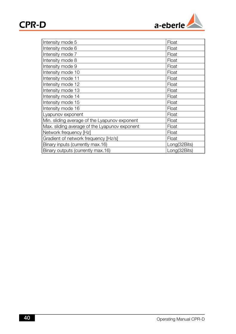
Intensitymode5 FloatIntensitymode6 FloatIntensitymode7 FloatIntensitymode8 FloatIntensitymode9 FloatIntensitymode10 FloatIntensitymode11 FloatIntensitymode12 FloatIntensitymode13 FloatIntensitymode14 FloatIntensitymode15 FloatIntensitymode16 FloatLyapunovexponent FloatMin.slidingaverageoftheLyapunovexponent FloatMax.slidingaverageoftheLyapunovexponent FloatNetworkfrequency[Hz] FloatGradientofnetworkfrequency[Hz/s] FloatBinaryinputs(currentlymax.16) Long(32Bits)Binaryoutputs(currentlymax.16) Long(32Bits)
CPR-D
OperatingManualCPR-D40
6 CPR-DasaSystemComponent
TheCPR-DcanbeconnectedtoalldevicesintheXXX-DXseries(REG-D, REG--D, REG-D,REG-DA,REG-DM, PAN-D, REG-DP, MMU-D, EOR-D etc.) of A. Eberle GmbH Co.-DM, PAN-D, REG-DP, MMU-D, EOR-D etc.) of A. Eberle GmbH Co.DM,PAN-D, REG-DP, MMU-D, EOR-D etc.) of A. Eberle GmbH Co.-D, REG-DP, MMU-D, EOR-D etc.) of A. Eberle GmbH Co.D,REG-DP,MMU-D,EOR-Detc.)ofA.EberleGmbHCo.KG'srangeofdevicestocreateameasurement,regulation,registrationcontrolandmonitoringsystem.TheindividualdevicesareconnectedviatheE-LANsystembus.Upto255dif-ferentdevicescancommunicatewitheachotheronanE-LAN.
Thefollowingexampleillustratesthesystemoverviewandinparticular,thebenefitresultingfromtheglobalviewofthedevices.
IfavoltageregulatorfromA.EberleGmbHCoKG'srangeisuseditisconnectedwiththeCPR-DviaE-LAN.
Intheeventofacollapsewarning,theCPR-Dcouldsendamessagetotheregu-latorwhichforcesittoshutdown.
Thiswouldbeaworthwhileapproachbecausevoltagedropscanoftenbeobservedaheadofacollapsewhichtheregulatorwouldnormallyneedtocompensateforbyincreasingthevoltage.However,additionalpowerwouldberequestedbyin-creasingthevoltagewhichcoulddestabilisetheunstablesystem.Afterthefault,theregulatorcouldalsobeswitchedbacktonormalmodeviathebus.
OperatingManualCPR-D 4
CPR-D
FeatureM00: 5relayoutputs6binaryinputs2mAoutputsStatusrelay
7 TechnicalDesign
7. The Hardware
TheCPR-DCollapsePredictionRelayisanextremelyflexiblecomponentfromboththehardwareandthesoftwareperspective.
Thebasicunitissuppliedasa19”plug-inmodule(18TE,3HE).Inadditiontousingstandard19”technology,allstandardmechanicalmountingandinstallationoptionscanbeused.
The19”plug-inmodulesmustbemountedinasuitablecontrolpanelmountingenclosureorwallmountingenclosureifdesired.
Theadvantageof19”technology:inprincipleonebasicunitcanbeusedforalldesigntypes.
Thisprovidessignificantsimplifications,particularlywithregardtothestorageandmaintenanceofdevices.
CPR-D
OperatingManualCPR-D4
8 ElectricalData
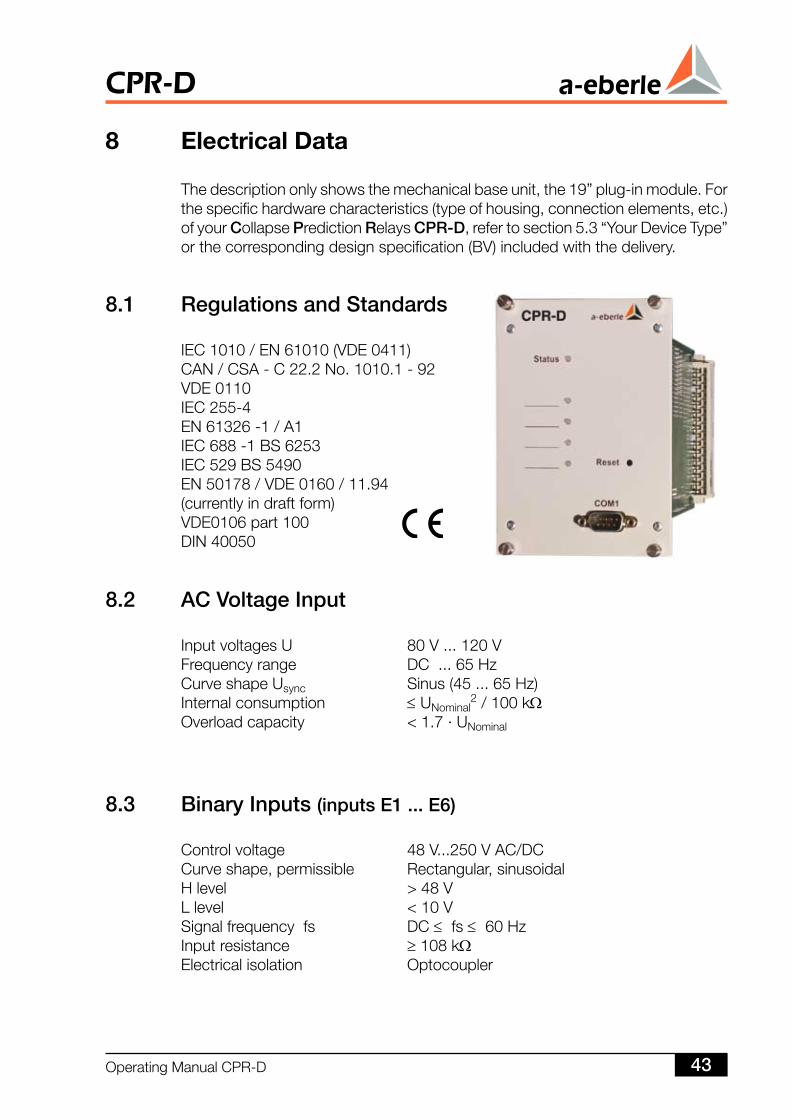
Thedescriptiononlyshowsthemechanicalbaseunit,the19”plug-inmodule.Forthespecifichardwarecharacteristics(typeofhousing,connectionelements,etc.)ofyourCollapsePredictionRelaysCPR-D,refertosection5.3“YourDeviceType”orthecorrespondingdesignspecification(BV)includedwiththedelivery.
8. Regulations and Standards
IEC1010/EN61010(VDE0411)CAN/CSA-C22.2No.1010.1-92VDE0110IEC255-4EN61326-1/A1IEC688-1BS6253IEC529BS5490EN50178/VDE0160/11.94(currentlyindraftform)VDE0106part100DIN40050
8. AC Voltage Input
InputvoltagesU 80V...120VFrequencyrange DC...65HzCurveshapeUsync Sinus(45...65Hz)Internalconsumption ≤UNominal
2/100kΩOverloadcapacity <1.7·UNominal
8.3 Binary Inputs (inputs E ... E6)
Controlvoltage 48V...250VAC/DCCurveshape,permissible Rectangular,sinusoidalHlevel >48VLlevel <10VSignalfrequencyfs DC≤fs≤60HzInputresistance ≥108kΩElectricalisolation Optocoupler
OperatingManualCPR-D 43
CPR-D
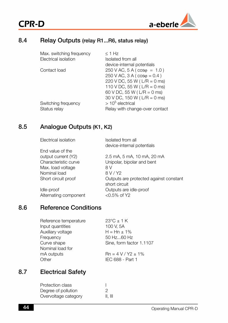
8.4 Relay Outputs (relay R...R6, status relay)
Max.switchingfrequency ≤1HzElectricalisolation Isolatedfromall device-internalpotentialsContactload 250VAC,5A(cosϕ=1.0) 250VAC,3A(cosϕ=0.4) 220VDC,55W(L/R=0ms) 110VDC,55W(L/R=0ms) 60VDC,55W(L/R=0ms) 30VDC,150W(L/R=0ms)Switchingfrequency >105electricalStatusrelay Relaywithchange-overcontact
8.5 Analogue Outputs(K, K)
Electricalisolation Isolatedfromall device-internalpotentialsEndvalueoftheoutputcurrent(Y2) 2.5mA,5mA,10mA,20mACharacteristiccurve Unipolar,bipolarandbentMax.loadvoltage 8VNominalload 8V/Y2Shortcircuitproof Outputsareprotectedagainstconstant shortcircuitIdle-proof Outputsareidle-proofAlternatingcomponent <0.5%ofY2
8.6 Reference Conditions
Referencetemperature 23°C±1KInputquantities 100V,5AAuxiliaryvoltage H=Hn±1%Frequency 50Hz...60HzCurveshape Sine,formfactor1.1107NominalloadformAoutputs Rn=4V/Y2±1%Other IEC688-Part1
8.7 Electrical Safety
Protectionclass IDegreeofpollution 2Overvoltagecategory II,III
CPR-D
OperatingManualCPR-D44
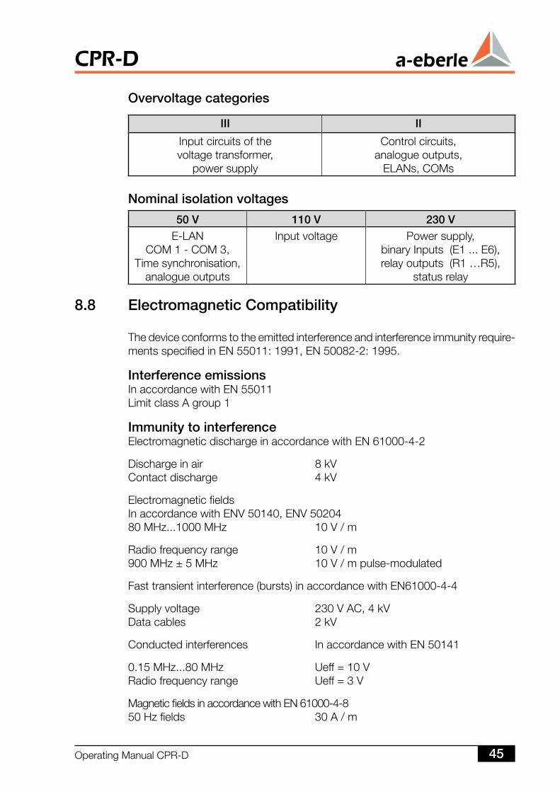
III II
Inputcircuitsofthevoltagetransformer,
powersupply
Controlcircuits,analogueoutputs,
ELANs,COMs
50 V 0 V 30 VE-LAN
COM1-COM3,Timesynchronisation,
analogueoutputs
Inputvoltage Powersupply,binaryInputs(E1...E6),relayoutputs(R1…R5),
statusrelay
Nominal isolation voltages
8.8 Electromagnetic Compatibility
Thedeviceconformstotheemittedinterferenceandinterferenceimmunityrequire-mentsspecifiedinEN55011:1991,EN50082-2:1995.
Interference emissionsInaccordancewithEN55011LimitclassAgroup1
Immunity to interferenceElectromagneticdischargeinaccordancewithEN61000-4-2
Dischargeinair 8kVContactdischarge 4kV
ElectromagneticfieldsInaccordancewithENV50140,ENV5020480MHz...1000MHz 10V/m
Radiofrequencyrange 10V/m900MHz±5MHz 10V/mpulse-modulated
Fasttransientinterference(bursts)inaccordancewithEN61000-4-4
Supplyvoltage 230VAC,4kVDatacables 2kV
Conductedinterferences InaccordancewithEN50141
0.15MHz...80MHz Ueff=10VRadiofrequencyrange Ueff=3V
MagneticfieldsinaccordancewithEN61000-4-850Hzfields 30A/m
Overvoltage categories
OperatingManualCPR-D 45
CPR-D
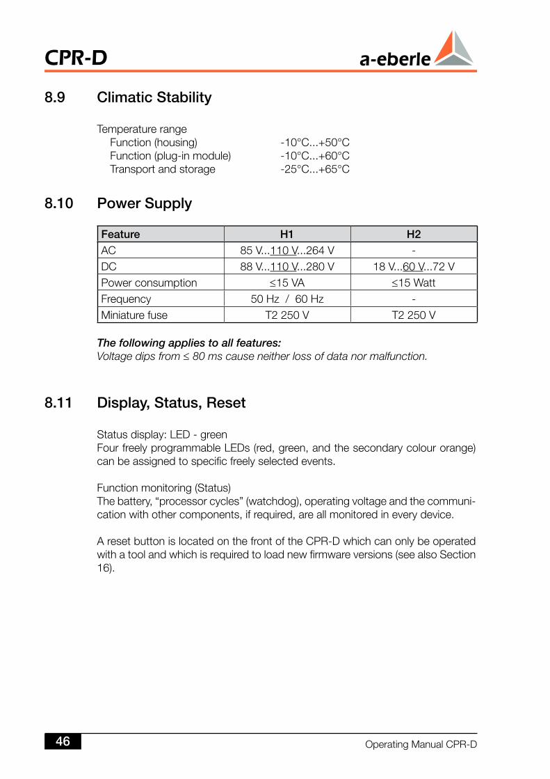
Feature H HAC 85V...110V...264V -DC 88V...110V...280V 18V...60V...72VPowerconsumption ≤15VA ≤15WattFrequency 50Hz/60Hz -Miniaturefuse T2250V T2250V
8.0 Power Supply
The following applies to all features:Voltage dips from ≤ 80 ms cause neither loss of data nor malfunction.
8.9 Climatic Stability
Temperaturerange Function(housing) -10°C...+50°C Function(plug-inmodule) -10°C...+60°C Transportandstorage -25°C...+65°C
8. Display, Status, Reset
Statusdisplay:LED-greenFourfreelyprogrammableLEDs(red,green,andthesecondarycolourorange)canbeassignedtospecificfreelyselectedevents.
Functionmonitoring(Status)Thebattery,“processorcycles”(watchdog),operatingvoltageandthecommuni-cationwithothercomponents,ifrequired,areallmonitoredineverydevice.
AresetbuttonislocatedonthefrontoftheCPR-Dwhichcanonlybeoperatedwithatoolandwhichisrequiredtoloadnewfirmwareversions(seealsoSection16).
CPR-D
OperatingManualCPR-D46
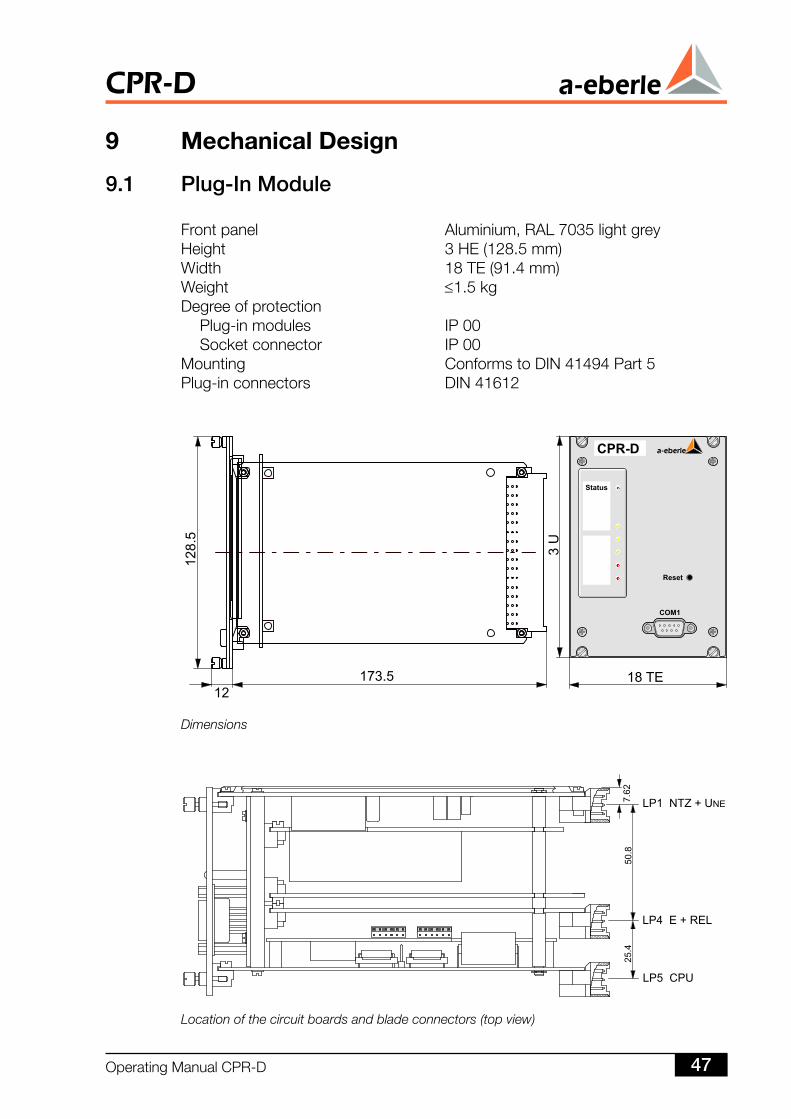
9. Plug-In Module
Frontpanel Aluminium,RAL7035lightgreyHeight 3HE(128.5mm)Width 18TE(91.4mm)Weight ≤1.5kgDegreeofprotection Plug-inmodules IP00 Socketconnector IP00Mounting ConformstoDIN41494Part5Plug-inconnectors DIN41612
9 MechanicalDesign
Dimensions
Location of the circuit boards and blade connectors (top view)
OperatingManualCPR-D 47
CPR-D
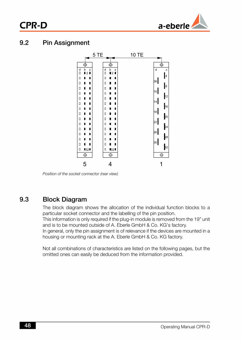
9. Pin Assignment
Position of the socket connector (rear view)
9.3 Block DiagramTheblockdiagramshows theallocationof the individual functionblocks toaparticularsocketconnectorandthelabellingofthepinposition.Thisinformationisonlyrequirediftheplug-inmoduleisremovedfromthe19”unitandistobemountedoutsideofA.EberleGmbHCo.KG'sfactory.Ingeneral,onlythepinassignmentisofrelevanceifthedevicesaremountedinahousingormountingrackattheA.EberleGmbHCo.KGfactory.
Notallcombinationsofcharacteristicsarelistedonthefollowingpages,buttheomittedonescaneasilybededucedfromtheinformationprovided.
CPR-D
OperatingManualCPR-D48
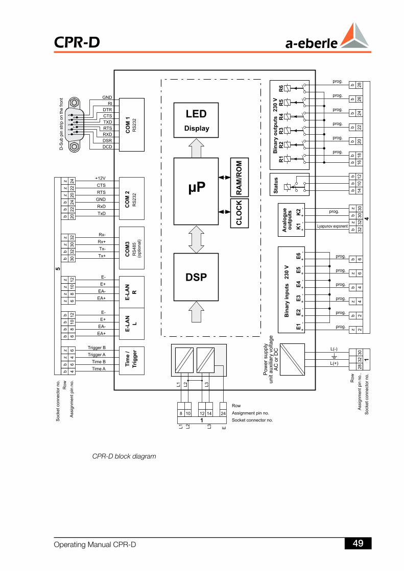
CPR-D block diagram
OperatingManualCPR-D 49
CPR-D
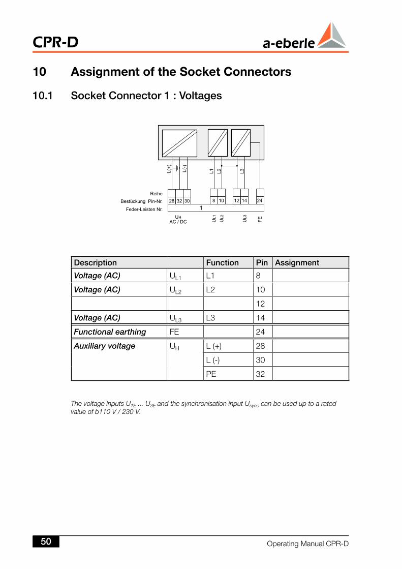
Description Function Pin Assignment
Voltage (AC) UL1 L1 8
Voltage (AC) UL2 L2 10
12
Voltage (AC) UL3 L3 14
Functional earthing FE 24
Auxiliary voltage UH L(+) 28
L(-) 30
PE 32
The voltage inputs U1E ... U3E and the synchronisation input Usync can be used up to a rated value of b110 V / 230 V.
0. Socket Connector : Voltages
10 AssignmentoftheSocketConnectors
CPR-D
OperatingManualCPR-D50
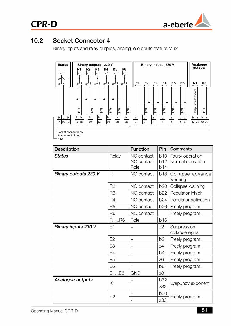
Description Function Pin Comments
Status Relay NCcontactNOcontactPole
b10b12b14
FaultyoperationNormaloperation
Binary outputs 230 V R1 NOcontact b18 Collapse advancewarning
R2 NOcontact b20 CollapsewarningR3 NOcontact b22 RegulatorinhibitR4 NOcontact b24 RegulatoractivationR5 NOcontact b26 Freelyprogram.R6 NOcontact Freelyprogram.R1...R6 Pole b16
Binary inputs 230 V E1 + z2 Suppressioncollapsesignal
E2 + b2 Freelyprogram.E3 + z4 Freelyprogram.E4 + b4 Freelyprogram.E5 + z6 Freelyprogram.E6 + b6 Freelyprogram.E1...E6 GND z8
Analogue outputsK1
+ b32Lyapunovexponent
- z32
K2+ b30
Freelyprogram.- z30
0. Socket Connector 4Binaryinputsandrelayoutputs,analogueoutputsfeatureM92
OperatingManualCPR-D 5
CPR-D
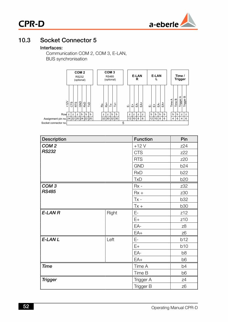
Description Function Pin
COM 2RS232
+12V z24CTS z22RTS z20GND b24RxD b22TxD b20
COM 3RS485
Rx- z32Rx+ z30Tx- b32Tx+ b30
E-LAN R Right E- z12E+ z10EA- z8EA+ z6
E-LAN L Left E- b12E+ b10EA- b8EA+ b6
Time TimeA b4TimeB b6
Trigger TriggerA z4TriggerB z6
0.3 Socket Connector 5Interfaces: CommunicationCOM2,COM3,E-LAN, BUSsynchronisation
CPR-D
OperatingManualCPR-D5
11 InterfacesThe CPR-Dhas several interfaces. Eachdevice is equippedwith theCOM1(RS232)asstandardwhichisusedbyaPCtohandletheparameterisationandthetransferofdata.TwoE-LANinterfacesarealsoincludedasstandardsothateachCPR-D is able to communicate with the system.-D is able to communicate with the system.Disabletocommunicatewiththesystem.Otherinterfacescanbeselectedifrequired.Forexample,adedicatedline(modem)canbeconnectedtoCOM2withoutblock-ingtheparameterisationinterfaceCOM1.TheCOM3RS485interfaceenablesadditionalinterfacemodules(ANA-D,BIN-D)tobeconnectedwhichextendsthehardwareresourcesofeverysingleCPR-Dbyincludingextraanalogueinputsandoutputsandextrabinaryinputsandoutputs.
. COM Interface (RS3, optional)TheCOM2serialinterfacecanbeused,amongstotherthings,toconnecttheCPR-DCollapsePredictionRelaytohigher-levelcontroldevices.ThecontrolcentrecouplingcardREG-P(X) can be connected viaCOM2 inordertocontroltheoutputoftheCPR-D,forexample,usingtheIEC870-5-101/103protocol.
. COM 3 Interface (RS485, optional)Upto15interfacemodules(BIN-D,ANA-D)canbeconnectedtoCOM3inanycombinationinordertoincreasethenumberofinputsandoutputs.
.3 E-LAN (Energy Local Area Network)TwoE-LANinterfacesareavailableontheCPR-Dasstandard.ThisensuresthateachCPR-Dhassystemcapability.TheE-LANisusedtolinkupto255E-LANbusstations(CPR-D,DMR-D,EOR-D,REG-DP, REG-D, REG-DA, REG-DM, MMU-D, PAN-D, PQI-D).-DP, REG-D, REG-DA, REG-DM, MMU-D, PAN-D, PQI-D).DP,REG-D,REG-DA,REG-DM,MMU-D,PAN-D,PQI-D).Allthestationscancommunicatewitheachotherorcanbecentrallycontrolled.
CharacteristicsoftheE-LAN 255busstationscanbeaddressed Multimasterstructure Integratedrepeaterfunction Canbeoperatedasopenring,busorcombinationofbusandring RecordbasedonSDLC/HDLCframes Transferrate15.6kbit/sand375kbit/s Telegramlength10...30bytes Averagethroughputapprox.100telegramsat62.5kbit/s
Forconfigurationsee“E-LAN(EnergyLocalAreaNetwork)”inWinCP.
OperatingManualCPR-D 53
CPR-D
12 ConfigurationInformationTheE-LAN(EnergyLocalAreaNetwork)isapowerfulbususedtorealisethecom-municationofallbusdevices.Itcanbeoperatedeitheras2-wire or 4-wire bus.-wire or 4-wire bus.wireor4-wirebus.Thebuscontrollercanstoreupto255addresses.Thismeansthat,theoretically,upto255A.EberleGmbHCo.KGdevicescanbeoperatedbyoneE-LAN, and-LAN, andLAN,andinextremecases,theycanallbereadandparameterisedusingasingleCOM1orCOM2(RS232)interface.
Itispossibletouseeithera2-wireand4-wireline-to-lineconnection,ortooper-ateupto32devicesinparallelusingadedicated2-wirelinesuchasastandardbusconnection.Combinationsofthetwotopologiesarepossible,asistheconversiontootherbus protocols and other physical media (fibre-optic cable connection, coaxialcable,etc.).Theline-to-linetopologyhasanE-LANcharacteristicwhichisparticularlyusefulfordistributedinstalleddevices.TwoRS485devicescanbeseparatedbyadistanceofupto1.2kmaccordingtothespecificationoftheRS485driver.However,sincetheCPR-D, likeallotherbuscomponents, isequippedwithadoubleinterface(E-LANrightandE-LANleft),eachbusdeviceactsasarepeater,meaningthatthedistancetobebridgedcanbeincreasedbyafurther1.2km.
Figure14showsaconfigurationinwhichfourCPR-Ds,withaddresses<A>to<D>,areoperatingonadedicated2-wirelineusingstandardbustechnology.Thedistancebetweenthesefourdevicesmaynotexceed1.2km.Asecondbuslineisopenedfromaddress<B>.Inthisexample,itleadstotwobusstations–aREG-Dvoltageregulator(address<E>)andaPetersoncoilregu-lator(address<F>).Inthisexample,anEOR-DisconnectedtotherighthandE-LANinterfaceoftheCPR-Dwithaddress<D>usinga4-wireconnection.Theissueofwhichdeviceshouldbeconnectedtotherightinterface,andwhichtotheleftinterfaceiseasilysettled:bothareacceptable.Thesystemcandetectwhichsortofdeviceisconnectedtowhichinterface(leftorright)andentersthecorrespondingbusstation(address,typeofdevice,connectiontype)intoitsownbusindex.Therefore,thebustypedoesnothavetobetakenintoconsiderationwhenplan-ninganE-LAN.However,itmustbeensuredthateachE-LANcomponenthasauniqueaddress(A...A9,B...B9,C...C9.....Z...Z4)andthatthetransferspeedandbustopologyare identicalbetweentwodevicesthatareconnectedwitheachother.Furthermore,ifatwo-coreconnectionisused,itmustbeensuredthatthefirstandlastbusconnectionareterminatedwitharesistor.Reflectionsattheendofthebusaresuppressedbytheresistor.ResistorsareavailableineverydeviceandcanbeactivatedordeactivatedusingWinCP.
CPR-D
OperatingManualCPR-D54
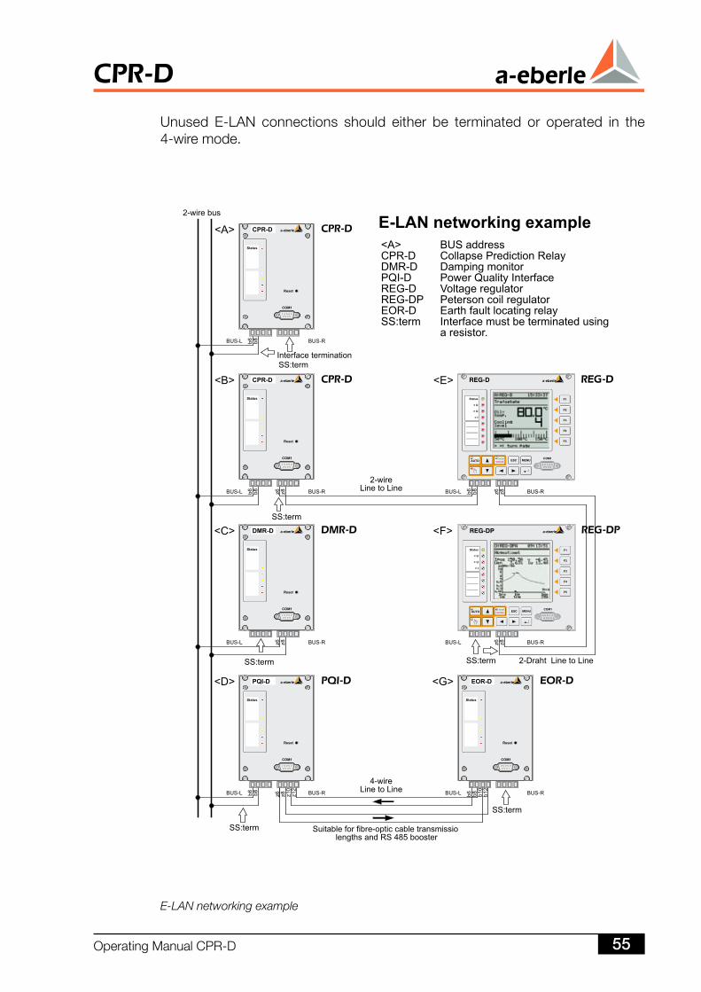
Unused E-LAN connections should either be terminated or operated in the4-wiremode.
E-LAN networking example
OperatingManualCPR-D 55
CPR-D
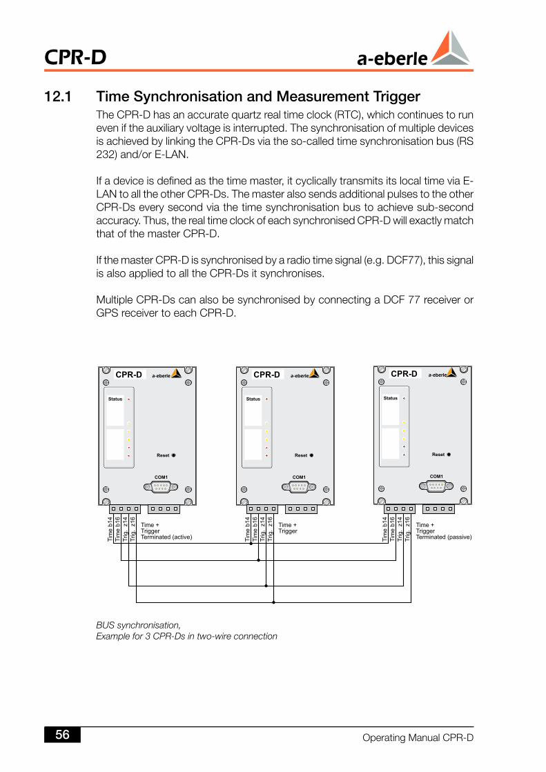
BUS synchronisation,Example for 3 CPR-Ds in two-wire connection
. Time Synchronisation and Measurement TriggerTheCPR-Dhasanaccuratequartzrealtimeclock(RTC),whichcontinuestoruneveniftheauxiliaryvoltageisinterrupted.ThesynchronisationofmultipledevicesisachievedbylinkingtheCPR-Dsviatheso-calledtimesynchronisationbus(RS232)and/orE-LAN.
Ifadeviceisdefinedasthetimemaster,itcyclicallytransmitsitslocaltimeviaE-LANtoalltheotherCPR-Ds.ThemasteralsosendsadditionalpulsestotheotherCPR-Dseverysecondviathetimesynchronisationbustoachievesub-secondaccuracy.Thus,therealtimeclockofeachsynchronisedCPR-DwillexactlymatchthatofthemasterCPR-D.
IfthemasterCPR-Dissynchronisedbyaradiotimesignal(e.g.DCF77),thissignalisalsoappliedtoalltheCPR-Dsitsynchronises.
MultipleCPR-DscanalsobesynchronisedbyconnectingaDCF77receiverorGPSreceivertoeachCPR-D.
CPR-D
OperatingManualCPR-D56
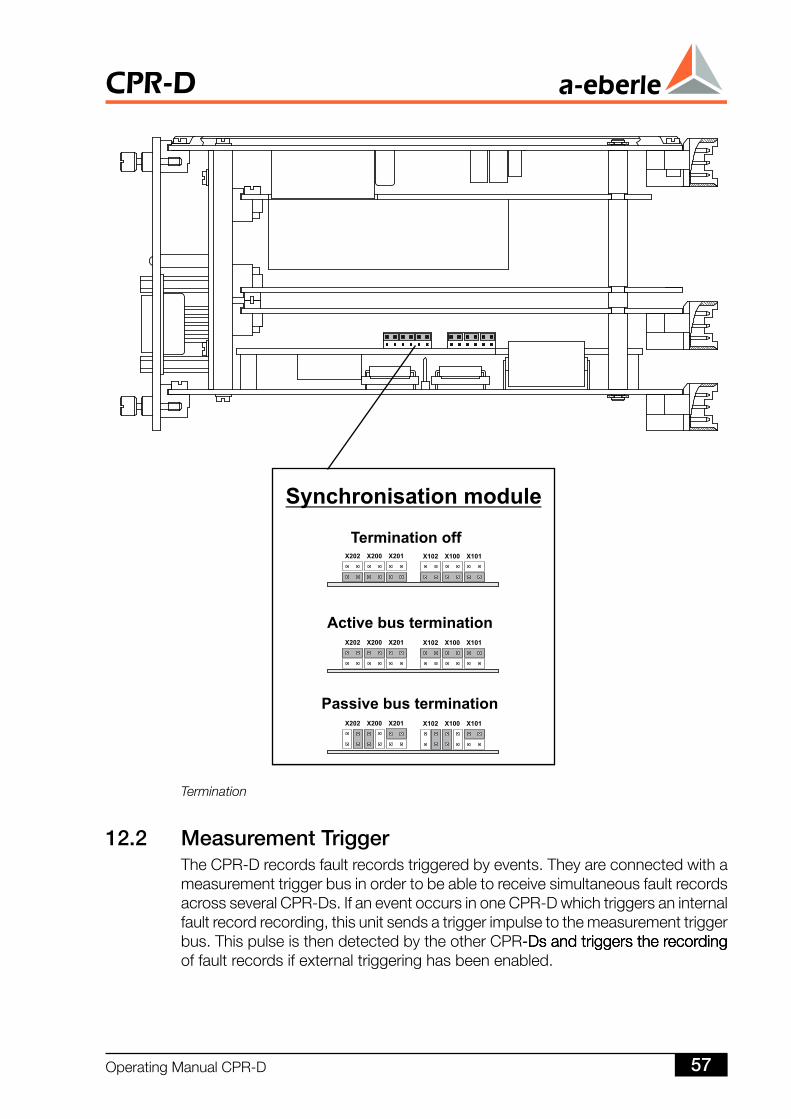
. Measurement TriggerTheCPR-Drecordsfaultrecordstriggeredbyevents.TheyareconnectedwithameasurementtriggerbusinordertobeabletoreceivesimultaneousfaultrecordsacrossseveralCPR-Ds.IfaneventoccursinoneCPR-Dwhichtriggersaninternalfaultrecordrecording,thisunitsendsatriggerimpulsetothemeasurementtriggerbus.ThispulseisthendetectedbytheotherCPR-Ds and triggers the recording-Ds and triggers the recordingDsandtriggerstherecordingoffaultrecordsifexternaltriggeringhasbeenenabled.
Termination
OperatingManualCPR-D 57
CPR-D
Thetimetriggercanalsobeusedtoretrospectivelydeducehowaparticulareventatinput1hasaffectedthevoltagequalityatoutput5.
Themeasurementtriggershouldalwaysbeactivatediftheexacttimesequenceofeventsisrequired.Timedifferencesofafewtenthsofamillisecondmayoccuriftime-criticaldataistransmittedovertheE-LAN,duetothebusrunningtime.
Fromtheelectricalpointofview,thetimesynchronisationbusandthemeasure-menttriggerbusexhibitthesamecharacteristicsastheE-LAN(RS485).However,incontrasttotheE-LAN,theinterfacesofthefirsttwocanonlybeconfiguredusingjumpers.AllCPR-Dsaresuppliedwiththeterminationswitchedoff.
ThedefaultvaluesdonothavetobealteredifoneormoreCPR-Dsareoperatedinasinglehousingor19”mountingrack.Thefirstandlastdevicesonthebusmustbecorrectlyterminatedifmultiplehousingsormountingracksareused(causingthebuslengthtobelongerthan50cm).For“time”and“measurementtrigger”signalsthereisadifferencebetweenactiveandpassivetermination.
Activeterminationterminatesthebuswiththewaveresistanceatthestartofthecableand,atthesametime,appliesthedrivingvoltagetotheappropriatebussegment.Ontheotherhand,apassivelyterminatedbusstationisnormallylocatedattheendofthecable,andissimplyterminatedwiththewaveresistanceinordertopreventreflections.
Forthisreason,thefirstdeviceonthebusmustbesettoactiveterminationandthelastdevicetopassivetermination.Theterminationremainsswitchedoffforalltheintermediatedevices,i.e.theyremaininthedefaultstatus.The jumpers for the two signals are located on an additional board which ismountedonthecircuitboardCPU(seefigureonpage57).
Atotalof32devicescanbeconnectedinthismanner.TheRS485driversspecificationstipulatesthatthemaximumseparationoftwodevicesshouldnotexceed1.2km.
CPR-D
OperatingManualCPR-D58
13 ParameterisationTheCPR-DCollapsePredictionRelaycanbeconnectedtotheE-LAN just like-LAN just likeLANjustlikeall other REGSys devices. A PC is used for the parameterisation and for thesynchronisationmanagementaswellastodisplaythemeasurementdataofthenetworkeddevices.ItcanbeconnectedtooneormoreCPR-Ds using the COM-Ds using the COMDsusingtheCOMinterface.ThecommunicationisimplementedviaREG-Lcommands.WinCPisavailableasprogram.
Thedatamanagementencompassesboth the internal (within thedevice)andexternal(withinthePC)managementofthemeasurementandparameterisationdata.Theusercanonlyaccess thesettings,statusesandmeasurementdataofthedevicesbyusingaPC(serialinterface)astheCPR-Dsdonotcontainacontrolelement.However,theunitsdonotrequireanyexternalcomputertocarryoutthemeas-urements.EachCPR-Dcanrecordmeasurementdataforacertainamountoftime,afterwhichtheinformationmustbetransferredtoaPC(database)asofflinedata.
AselectionofthecurrentmeasurementquantitiescanbetransferredtothePCasreal-timedata,eithercontinuouslyorallatonce.Theselectionisnotaffectedbytheconfigurationoftherecordingofthemeasurementdata.Bothreal-timeandofflinedatacanbedisplayed.Intheinterestsofefficientutilisationofthedevice's“memory”and“transmissioncapacity”resources,theuserneedstoselectthequantitiesthataretobeper-manentlyrecorded.
Theparameterisationandprogrammingof theCPR-D iscarriedoutusing theWinCPsoftware.
Thesoftware isdatabase-oriented, i.e.allmeasureddatacanbestoredinthedatabaseandcanthusbeeasilylocatedagainandedited.
TheWinCPsoftware is inevitablycomplex inorder tobeabletoutilisethe fullpotentialoftheCPR-D.Thispresentstheproblemofanappropriatedescription.Ontheonehand,thesoftwareshouldbesetupbyasoftwareinstallerfromA.EberleGmbHCo.KG.Thesetupprocedureshouldbefollowedbytraining.Ontheotherhand,ausercannotbeexpectedtostudy200pagesoftextforasinglefacilityinstallation.Forthisreason,onlythekeyWinCPsoftwarefunctionsareshowninthisoperatingmanualintheformofscreenshots.
Furtherimportantinformationcanbeobtainedfromtheprogram'shelppages.
OperatingManualCPR-D 59
CPR-D
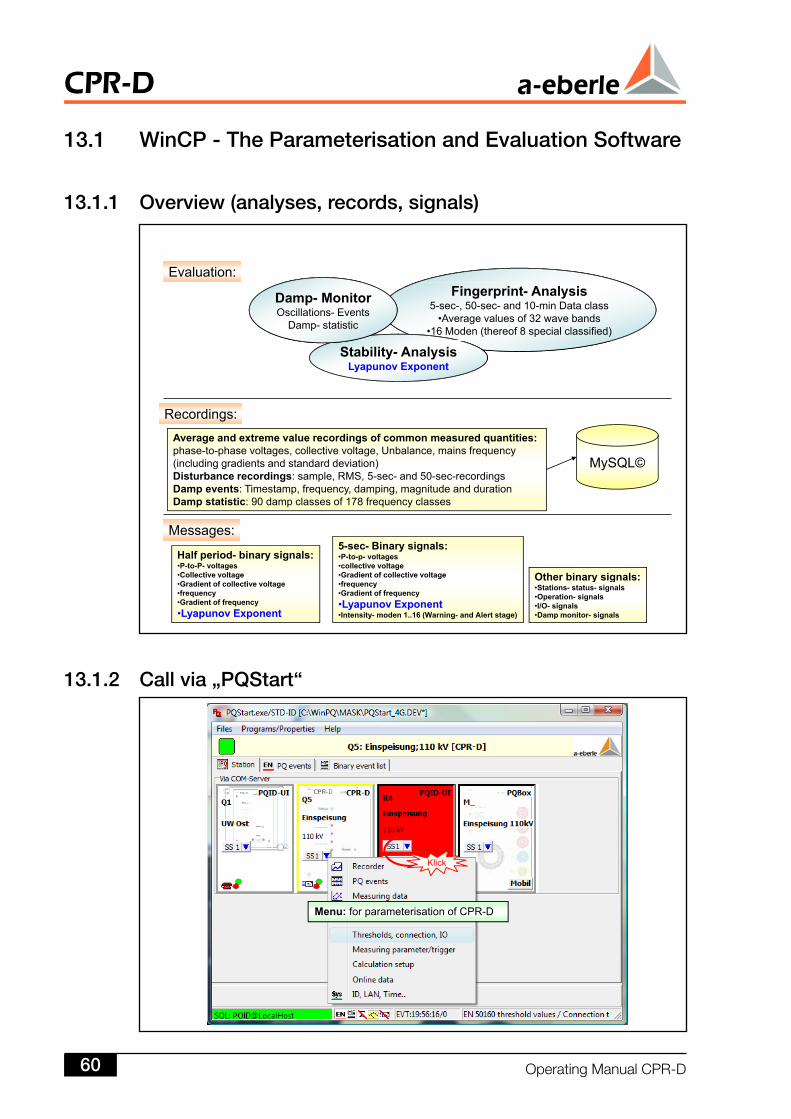
Evaluation:Fingerprint- Analysis
5-sec-, 50-sec- and 10-min Data class•Average values of 32 wave bands
•16 Moden (thereof 8 special classified)
Damp- MonitorOscillations- Events
Damp- statistic
Stability- AnalysisLyapunov Exponent
Average and extreme value recordings of common measured quantities:phase-to-phase voltages, collective voltage, Unbalance, mains frequency
Recordings:
M SQL©(including gradients and standard deviation)Disturbance recordings: sample, RMS, 5-sec- and 50-sec-recordingsDamp events: Timestamp, frequency, damping, magnitude and durationDamp statistic: 90 damp classes of 178 frequency classes
MySQL©
Half period- binary signals:•P-to-P- voltages •Collective voltage
5-sec- Binary signals:•P-to-p- voltages•collective voltage•Gradient of collective voltage
Messages:
Other binary signals:•Collective voltage•Gradient of collective voltage•frequency•Gradient of frequency•Lyapunov Exponent
•Gradient of collective voltage•frequency•Gradient of frequency•Lyapunov Exponent•Intensity- moden 1..16 (Warning- and Alert stage)
Other binary signals:•Stations- status- signals•Operation- signals•I/O- signals•Damp monitor- signals
Klick
Menu: for parameterisation of CPR-D
3. WinCP - The Parameterisation and Evaluation Software
3.. Overview (analyses, records, signals)
3.. Call via „PQStart“
CPR-D
OperatingManualCPR-D60
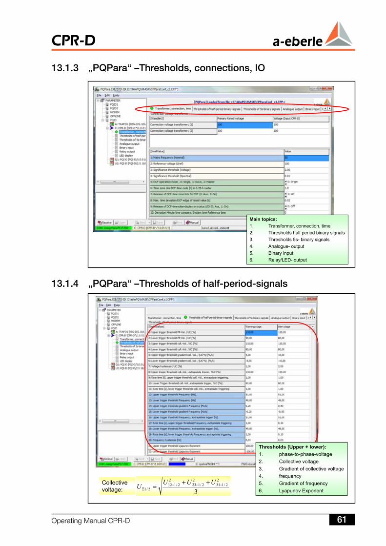
Main topics:1. Transformer, connection, time2. Thresholds half period binary signals3. Thresholds 5s- binary signalsy g4. Analogue- output5. Binary input6. Relay/LED- output
Thresholds (Upper + lower):1. phase-to-phase-voltage2. Collective voltage3. Gradient of collective voltage
3
22/131
22/123
22/112
2/1−−−
Σ++= UUUUCollective
voltage:
g4. frequency5. Gradient of frequency6. Lyapunov Exponent
3..3 „PQPara“ –Thresholds, connections, IO
3..4 „PQPara“ –Thresholds of half-period-signals
OperatingManualCPR-D 6
CPR-D
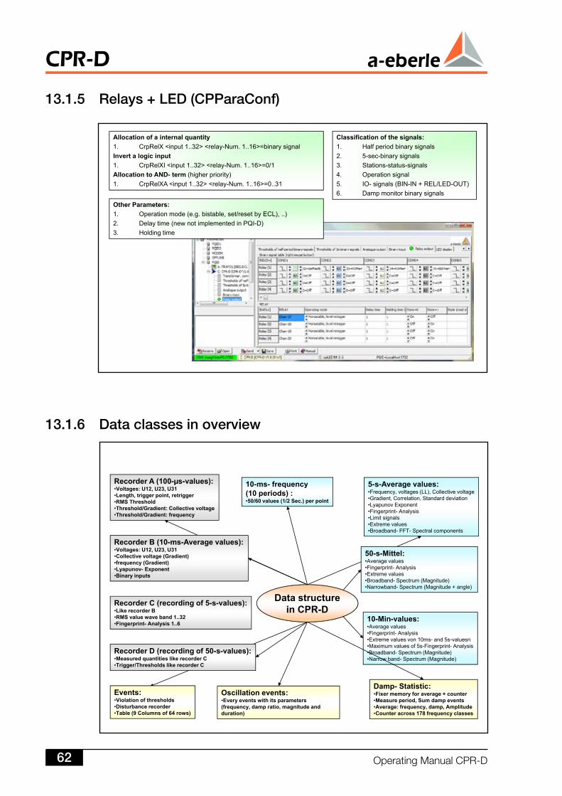
3..5 Relays + LED (CPParaConf)
3..6 Data classes in overview
Allocation of a internal quantity1. CrpRelX <input 1..32> <relay-Num. 1..16>=binary signalInvert a logic input 1 CrpRelXI <inp t 1 32> <rela N m 1 16> 0/1
Classification of the signals:1. Half period binary signals2. 5-sec-binary signals3 Stations stat s signals1. CrpRelXI <input 1..32> <relay-Num. 1..16>=0/1
Allocation to AND- term (higher priority)1. CrpRelXA <input 1..32> <relay-Num. 1..16>=0..31
Other Parameters:
3. Stations-status-signals4. Operation signal5. IO- signals (BIN-IN + REL/LED-OUT)6. Damp monitor binary signals
Other Parameters:1. Operation mode (e.g. bistable, set/reset by ECL), ..)2. Delay time (new not implemented in PQI-D)3. Holding time
10 ms frequency 5 s Average values:Recorder A (100-µs-values): 10-ms- frequency(10 periods) :•50/60 values (1/2 Sec.) per point
5-s-Average values:•Frequency, voltages (LL), Collective voltage•Gradient, Correlation, Standard deviation •Lyapunov Exponent•Fingerprint- Analysis•Limit signals•Extreme values
Recorder A (100 µs values):•Voltages: U12, U23, U31•Length, trigger point, retrigger•RMS Threshold•Threshold/Gradient: Collective voltage•Threshold/Gradient: frequency
Extreme values•Broadband- FFT- Spectral components
Recorder B (10-ms-Average values):•Voltages: U12, U23, U31•Collective voltage (Gradient)•frequency (Gradient)
50-s-Mittel:•Average valuesFingerprint Analysis
Data structurein CPR D
Recorder C (recording of 5-s-values):
•Lyapunov- Exponent•Binary inputs
•Fingerprint- Analysis•Extreme values•Broadband- Spectrum (Magnitude)•Narrowband- Spectrum (Magnitude + angle)
in CPR-D10-Min-values:•Average values•Fingerprint- Analysis•Extreme values von 10ms- and 5s-valuesn•Maximum values of 5s-Fingerprint- Analysis
•Like recorder B•RMS value wave band 1..32•Fingerprint- Analysis 1..6
Recorder D (recording of 50 s values): •Broadband- Spectrum (Magnitude)•Narrow band- Spectrum (Magnitude)
Oscillation events:Damp- Statistic:
Recorder D (recording of 50-s-values):•Measured quantities like recorder C•Trigger/Thresholds like recorder C
Events: Oscillation events:•Every events with its parameters (frequency, damp ratio, magnitude and duration)
•Fixer memory for average + counter•Measure period, Sum damp events•Average: frequency, damp, Amplitude•Counter across 178 frequency classes
Events:•Violation of thresholds•Disturbance recorder •Table (9 Columns of 64 rows)
CPR-D
OperatingManualCPR-D6
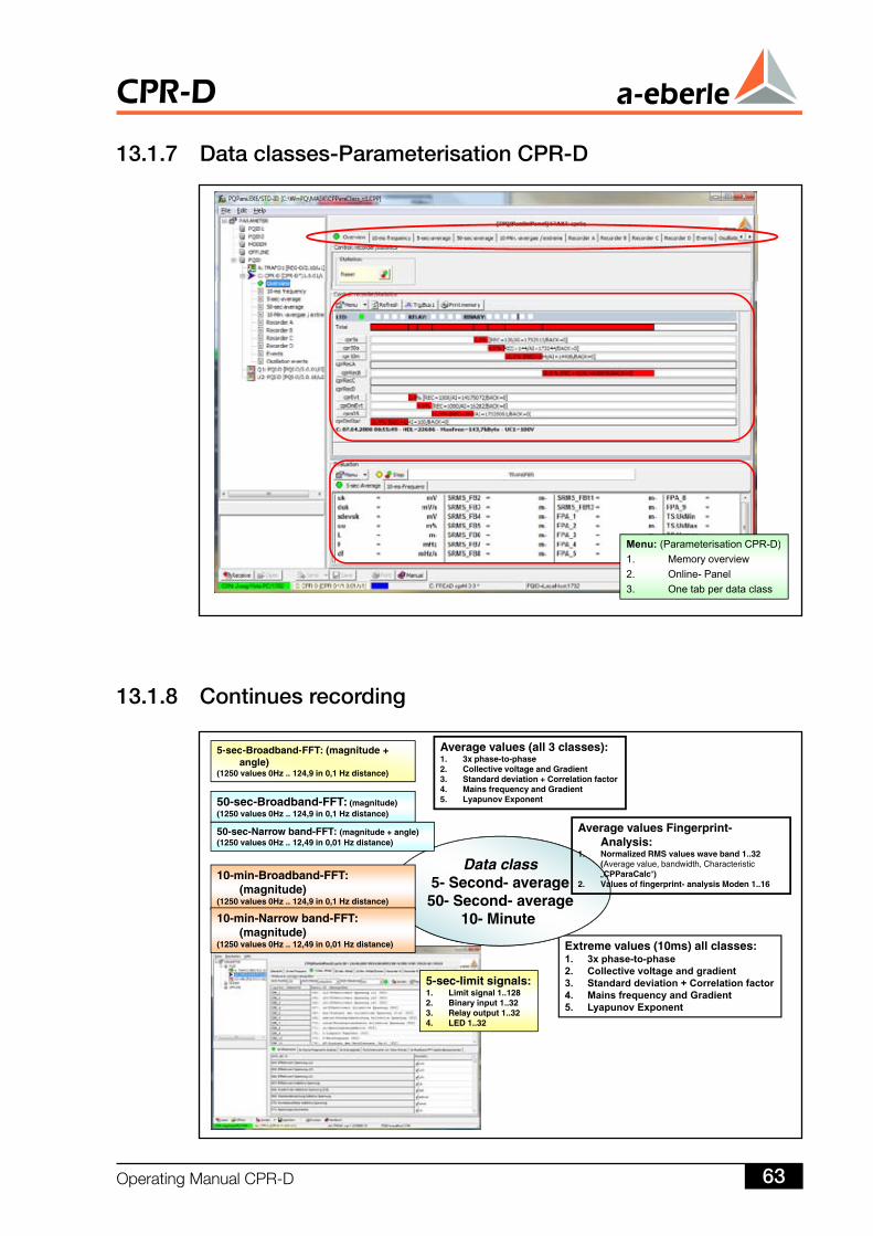
Average values (all 3 classes):5-sec-Broadband-FFT: (magnitude + Average values (all 3 classes):1. 3x phase-to-phase2. Collective voltage and Gradient 3. Standard deviation + Correlation factor4. Mains frequency and Gradient5. Lyapunov Exponent
5-sec-Broadband-FFT: (magnitude +angle)
(1250 values 0Hz .. 124,9 in 0,1 Hz distance)
50-sec-Broadband-FFT: (magnitude)(1250 values 0Hz .. 124,9 in 0,1 Hz distance)
Data class5 Second average
Average values Fingerprint-Analysis:
1. Normalized RMS values wave band 1..32 (Average value, bandwidth, Characteristic „CPParaCalc“)10-min-Broadband-FFT:
(1250 values 0Hz .. 124,9 in 0,1 Hz distance)
50-sec-Narrow band-FFT: (magnitude + angle)(1250 values 0Hz .. 12,49 in 0,01 Hz distance)
Extreme values (10ms) all classes:
5- Second- average50- Second- average
10- Minute
2. Values of fingerprint- analysis Moden 1..16(magnitude)(1250 values 0Hz .. 124,9 in 0,1 Hz distance)
10-min-Narrow band-FFT: (magnitude)
(1250 values 0Hz 12 49 in 0 01 Hz distance)
5-sec-limit signals:1. Limit signal 1..1282. Binary input 1..32
Extreme values (10ms) all classes:1. 3x phase-to-phase2. Collective voltage and gradient 3. Standard deviation + Correlation factor4. Mains frequency and Gradient5. Lyapunov Exponent
(1250 values 0Hz .. 12,49 in 0,01 Hz distance)
3. Relay output 1..324. LED 1..32
5. Lyapunov Exponent
Menu: (Parameterisation CPR-D)( )1. Memory overview2. Online- Panel3. One tab per data class
3..7 Data classes-Parameterisation CPR-D
3..8 Continues recording
OperatingManualCPR-D 63
CPR-D
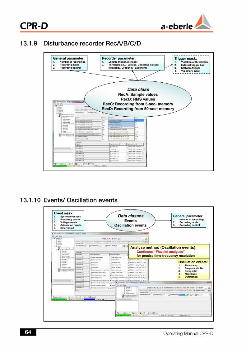
General parameter:1. Number of recordings2. Recording mode3. Recording control
Trigger mask:1. Violation of thresholds2. External trigger bus3. Software trigger4. Via binary input
Recorder parameter:1. Length, trigger, retrigger2. Thresholds (LL- voltage, Collective voltage,
frequency, Lyapunov- Exponent)
Data classRecA: Sample valuesRecA: Sample values
RecB: RMS valuesRecC: Recording from 5-sec- memoryRecD: Recording from 50-sec- memory
General parameter:1. Number of recordings2. Recording mode3. Recording control
Event mask:1. System messages2. Frequency events3. Voltage events4. Calculation results 5. Binary input
Data classesEvents
Oscillation events
Analyse method (Oscillation events):
Oscillation events:1. Timestamp
Analyse method (Oscillation events):Continues “Wavelet analyses”for precise time-frequency resolution
2. Frequency in Hz3. Damp ratio4. Magnitude5. Duration [s]
3..9 Disturbance recorder RecA/B/C/D
3..0 Events/ Oscillation events
CPR-D
OperatingManualCPR-D64
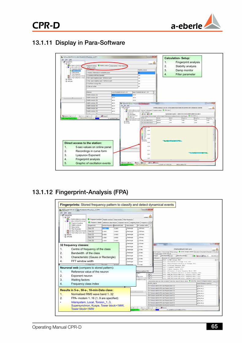
Fingerprints: Stored frequency pattern to classify and detect dynamical events
32 f l32 frequency classes:1. Centre of frequency of the class2. Bandwidth of the class3. Characteristic (Gauss or Rectangle)4. FFT window width
Neuronal web (compare to stored pattern):1. Reference value of the neuron2. Exponent neuron3 Waiting factors
Results in 5-s-, 50-s-, 10-min-Data class: 1. Normalised RMS wave band 1..322 FPA modem 1 16 (1 9 are specified)
3. Waiting factors4. Frequency class index
2. FPA- modem 1..16 (1..9 are specified)• Intersystem, Local, Torsion_1..3,
Supersynchron, Kuspe, Tower block>1MW, Tower block<1MW
Calculation- Setup:1 Fingerprint analysis1. Fingerprint analysis2. Stability analysis3. Damp monitor4. Filter parameter
Direct access to the station:1. 5-sec-values on online panel2. Recordings in curve formg3. Lyapunov Exponent4. Fingerprint analysis5. Graphic of oscillation events
3.. Display in Para-Software
3.. Fingerprint-Analysis (FPA)
OperatingManualCPR-D 65
CPR-D
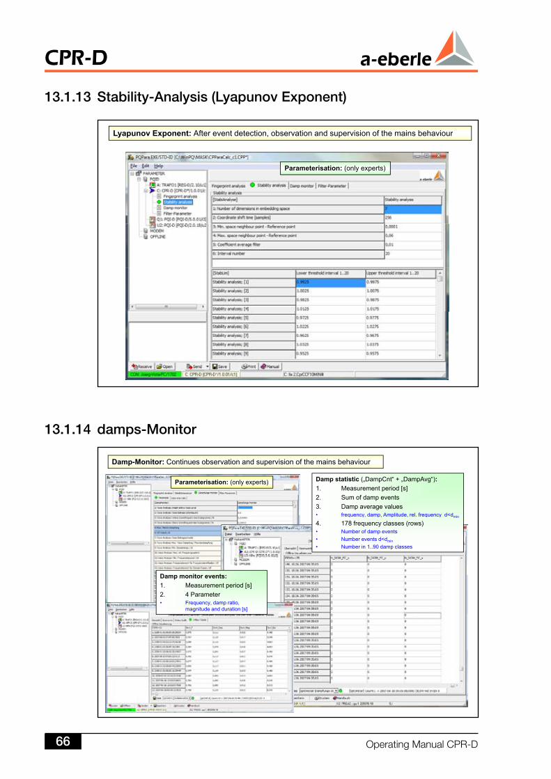
Damp-Monitor: Continues observation and supervision of the mains behaviour
Parameterisation: (only experts) Damp statistic („DampCnt“ + „DampAvg“):1. Measurement period [s]2. Sum of damp events3. Damp average values
frequency damp Amplitude rel frequency d<d• frequency, damp, Amplitude, rel. frequency d<dmin
4. 178 frequency classes (rows)• Number of damp events• Number events d<dmin
• Number in 1..90 damp classes
Damp monitor events:1. Measurement period [s]2 4 Parameter2. 4 Parameter• Frequency, damp ratio,
magnitude and duration [s]
3..3 Stability-Analysis (Lyapunov Exponent)
3..4 damps-Monitor
Lyapunov Exponent: After event detection, observation and supervision of the mains behaviour
Parameterisation: (only experts)
Lyapunov Exponent: After event detection, observation and supervision of the mains behaviour
CPR-D
OperatingManualCPR-D66
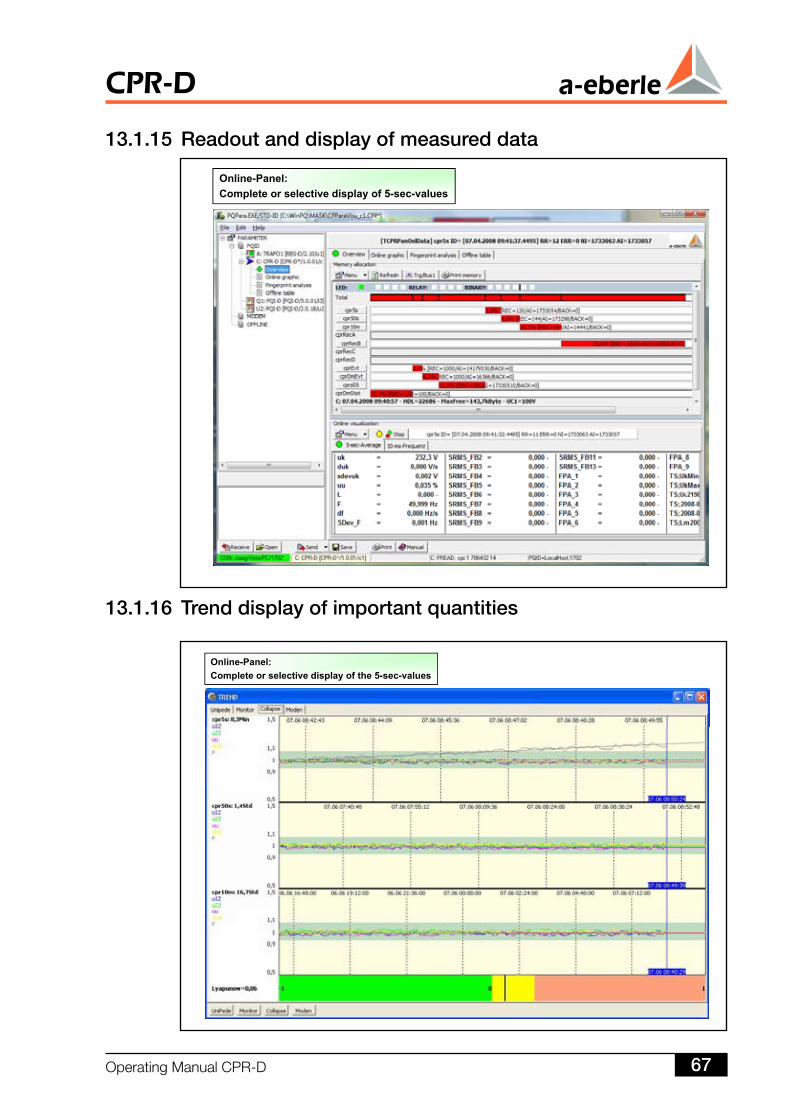
Online Panel:Online-Panel:Complete or selective display of 5-sec-values
3..5 Readout and display of measured data
3..6 Trend display of important quantities
Online-Panel:Complete or selective display of the 5-sec-values
OperatingManualCPR-D 67
CPR-D
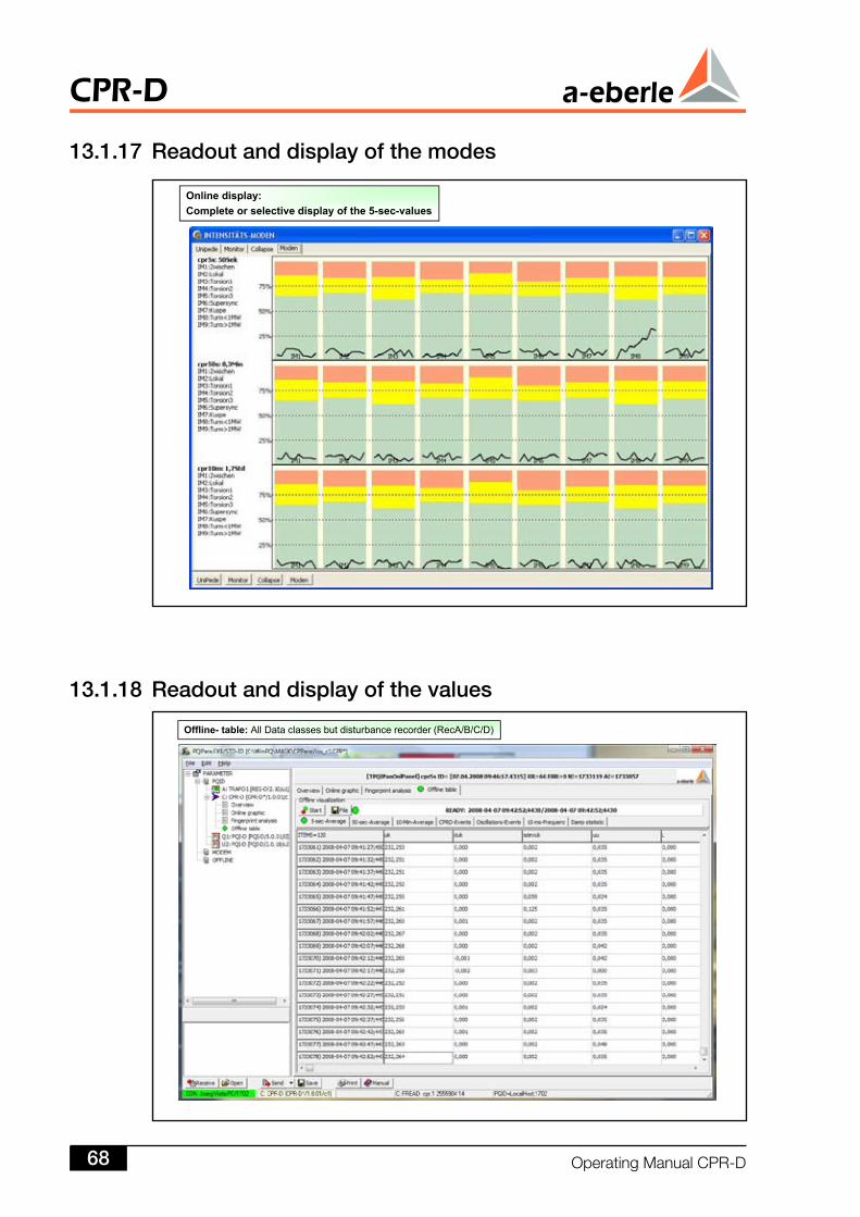
Offline- table: All Data classes but disturbance recorder (RecA/B/C/D)
3..7 Readout and display of the modes
3..8 Readout and display of the values
Online display:p yComplete or selective display of the 5-sec-values
CPR-D
OperatingManualCPR-D68
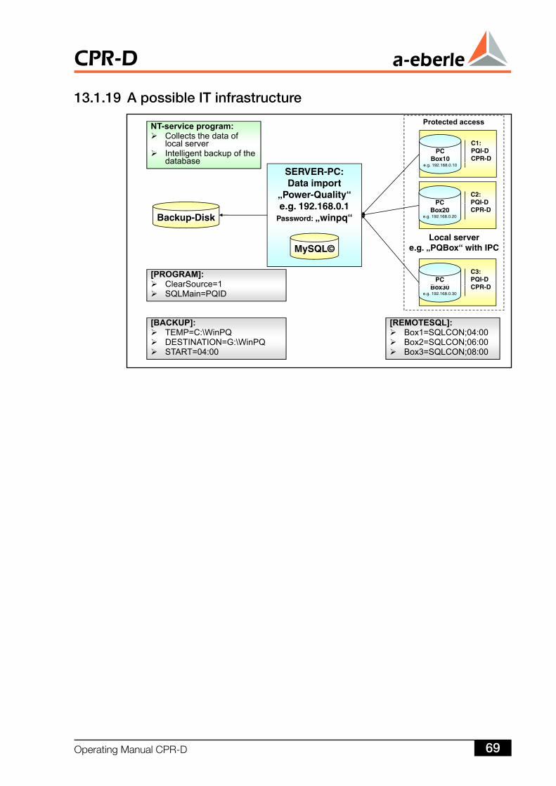
Protected accessNT-service program:Collects the data of local serverIntelligent backup of the database
Protected access
C1:PQI-DCPR-D
PCBox10database
SERVER-PC:Data import
„Power-Quality“192 168 0 1
C2:PQI-DPC
e.g. 192.168.0.10
e.g. 192.168.0.1Password: „winpq“Backup-Disk
Local serverPQB “ i h IPC
PQI DCPR-D
PCBox20
e.g. 192.168.0.20
MySQL©
[PROGRAM]:ClearSource=1
e.g. „PQBox“ with IPC
C3:PQI-DCPR D
PCB 30
[REMOTESQL]:[BACKUP]:
ClearSource 1SQLMain=PQID
CPR-DBox30e.g. 192.168.0.30
[ ]Box1=SQLCON;04:00Box2=SQLCON;06:00Box3=SQLCON;08:00
[ ]TEMP=C:\WinPQDESTINATION=G:\WinPQSTART=04:00
3..9 A possible IT infrastructure
OperatingManualCPR-D 69
CPR-D
14 Startup
4. Safety Information
Beforeyoubeginusingthedevice,youneedtobeawareofsomeofthedangerswhichmayoccurifthedeviceisusedimproperly.
ThisisaprotectionclassIdevice.Pleaseconnectthedevice’sprotectiveearthconductortoyoursystem’searthingsystembeforethedeviceisconnectedtoavoltagesupply.
Thedevicemaynotbeusedtocarryoutmeasurementsoncircuitsthatcontaincoronadischarges.
Thedevicemustberemovedfromthenetworkimmediatelyifitisfoundthatthedevicecannolongerbeoperatedsafelyduetoamechanicalorelectricalfault.
Pleasenotethatthereisadangertolifewhereveravoltagewithanamplitude>30Vr.m.s.ispresent.
4. Step-by-Step ProcedurePreparation:
Pleasecheckthenameplateandconfirmthatthesupplieddeviceconformstoyourrequirements.
Isthevoltagesupplycorrect? Note: changestothevoltagesupplyrangecanonlybecarriedoutinourfac-
tory.
Aretheratedvaluesfortheinputvoltagescorrect?
PartoftheWinCPprogramisspecificallydesignedfortheparameterisationandprogrammingoftheanalogueoutputs,binaryinputsandtheLEDs.
CPR-D
OperatingManualCPR-D70
15 Applications
5. Application-Specific Programming
ProgramsforspecifictaskscaneitherbewrittenindependentlyusingREG-Lorcanberequestedfromourheadoffice.Anexampleofanapplication-specificprogramisgiveninSection2.3.
16 UpdatingtheFirmwareTheplug-inmodulemustbedisconnectedfromthepowersupplybeforeupdat-ingthefirmware.
Theresetbuttonmustremainpressedinwhenthevoltagesupplyisconnected.
The status LED changes colour to indicate that the device is in the updatemode.Ifitisred,itmeansthedeviceisreadytobeupdated.
Thefirmwareupdatemustbecarriedoutdirectlyonthedeviceitself,andrequiresthefollowingsteps:
Establishaphysicalconnectionbetween theCPR-Dand thezeromodemcable.
Theprogram“COMM.EXE”canbefoundinthe“Firmware”folder,which islocated inthedirectorycontainingtheWinPQprogram.Touploadthenewfirmware,selectatransferspeedof115baudand“RTS/CTS”forthehardwareprotocol.
ThestationisthenputintheFirmwareUploadMode(pressandholdresetbuttonforatleast5secends).ThestatusLEDthencomesoninred.
In the program “COMM.EXE” menu: Select “Send Terminal/Firmware withReset”.
Thefamiliar“OpenFileDialog”of“Windows”isshown.Thevalidfirmwarefile(e.g.PQI_UU.MOT)mustbeopened.Thedatatransferbeginsimmediately.Thestatusoftheuploadcanbefollowedintheprogramstatusline.
Verifytheversionnumberontheterminaloncetheuploadiscomplete(3to5minutes).Thecommandiscalled“VER”,theresponsemayappearasfollows:“PQI-D:Version2.0.10of23-07-04”
Next:Enter“SYSRESET=590”.Thestationisrestarted.ThestatusLEDwilllightupagainafterapproximately8seconds.
OperatingManualCPR-D 7
CPR-D
17 ScopeofDelivery
CPR-Daccordingtodesignfeatures
Operatingmanual
Supplement
CPR-D
OperatingManualCPR-D7
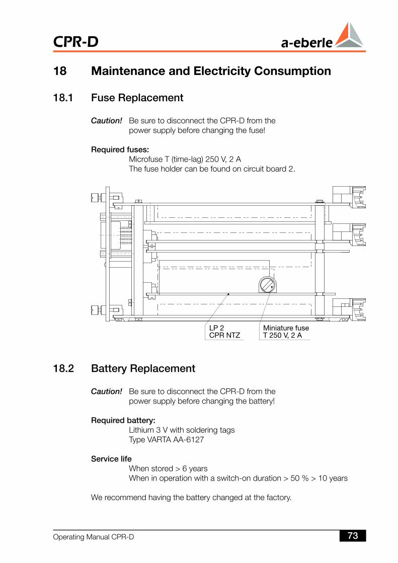
18 MaintenanceandElectricityConsumption
8. Fuse Replacement
Caution! BesuretodisconnecttheCPR-Dfromthe powersupplybeforechangingthefuse!
Required fuses: MicrofuseT(time-lag)250V,2A Thefuseholdercanbefoundoncircuitboard2.
8. Battery Replacement
Caution! BesuretodisconnecttheCPR-Dfromthe powersupplybeforechangingthebattery!
Required battery: Lithium3Vwithsolderingtags TypeVARTAAA-6127
Service life Whenstored>6years Wheninoperationwithaswitch-onduration>50%>10years
Werecommendhavingthebatterychangedatthefactory.
OperatingManualCPR-D 73
CPR-D
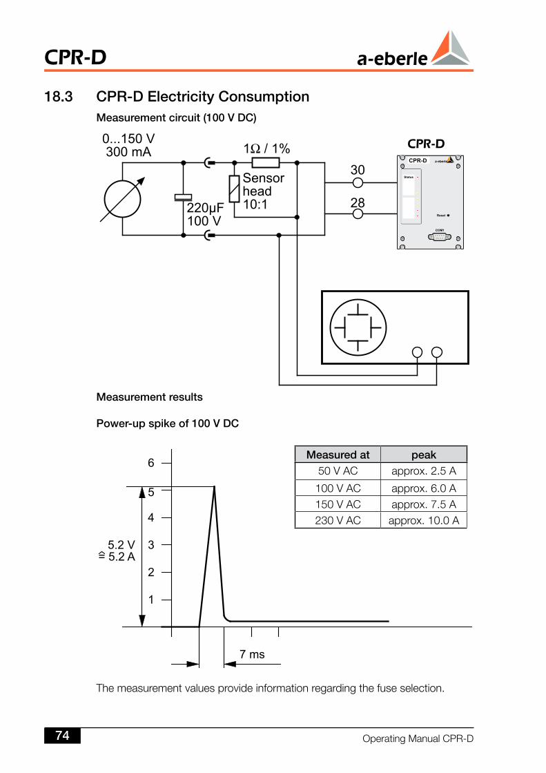
Measured at peak50VAC approx.2.5A
100VAC approx.6.0A150VAC approx.7.5A230VAC approx.10.0A
8.3 CPR-D Electricity ConsumptionMeasurement circuit (00 V DC)
Measurement results
Power-up spike of 00 V DC
Themeasurementvaluesprovideinformationregardingthefuseselection.
CPR-D
OperatingManualCPR-D74
20 Warranty
Thewarrantyisvalidforthreeyearsfromthedateofdelivery.
19 StorageInformation
Thedevicesshouldbestoredinclean,dryrooms.Thedevicesandtheirrespectivereplacementmodulescanbestoredbetween-25°Cand+65°C.
Therelativehumiditymustnot lead to the formationofeithercondensationorice.
Werecommendthatthestoragetemperatureiskeptatbetween+0°Cto+55°Ctoensurethatthebuilt-inelectrolyticcapacitordoesnotageprematurely.
Wealsorecommendthatthedevicebeconnectedtoanauxiliaryvoltageeverytwoyearstoreformtheelectrolyticcapacitors.Thisprocedureshouldalsobecar-riedoutbeforethedeviceisputintooperation.Underextremeclimaticconditions(tropics),thisalsoensures“pre-heating”atthesametimeandhelpstoavoidtheformationofcondensation.
Thedeviceshouldbestoredintheserviceroomforatleasttwohourspriortobeingconnectedtothevoltageforthefirsttimesothatitcanbecomeaccus-tomedtotheambienttemperaturethereandtoavoidtheformationofmoistureandcondensation.
OperatingManualCPR-D 75
CPR-D
. Index
Symbole
AAutomatic status device 9
BBifurcation theory 6, 8Bivalent statement logic 15Blackout 6Block diagram 12Boolean logic 15Breakdown 8
CCanay 17Classical measuring technology 6Clustering 13Collapse 6Connection matrix 15CPR-D Collapse Prediction Relay 6Creeping network breakdown 9Critical operating condition 6
DDamping monitor 21Damping profile 9Degree of order 20Deterministic chaos 6Development lines 20Downwind tower shade 17Downwind tower shade or wind barrier effect 17Drift process 9Dynamic network control 7
EEarly blackout detection 7Economic benefits 6Enveloping oscillations 12Event recorder 10
FFault record 10Feeding capacity 6Fingerprint 9Frequency interval class 14Frequency modes 21
Frequency relay functions 9Fuzzy logic 15
GGlobal load dynamics 9
HHarmonics 6High voltage and extra-high voltage network 8Hopf bifurcation 9Hopf bifurcation point 13Hopf point 9
IIEC 61850 8IEEE model 13Independent network 10Information before and after event 10Inhibit regulator 9Inter-area oscillations 7, 13Interface cards IEC 61850 8Interharmonics 6Intermediate system oscillations 9, 16
J
KKuspe 19
LLiability 2Load dynamics 6Load oscillations 9Load shedding 10Load step change 12Local mode 16Lyapunov exponent 7
MModal system characteristics 21Morlet-Wavelet 12
NNetwork planning 7Network topology 6NEURON 15Non-linear dynamic 8Non-linear dynamics 6
OOptimised network utilization 7
CPR-D
OperatingManualCPR-D76
Oscillations 16Output frequency controller 13
PPhase swinging 12Plant mode 16Power demand 6Pre-trigger, post-trigger times 10Prevention of major interferences 7Printing errors 2
Q
RReference model 9Regenerative energy transformers 7Resonant frequency 12Rotor 16Rotor phase difference 17
SSignatures 12Spectral analysis 12Stability reserve 6, 9Statistic evaluation 7Subharmonics 12Subsynchronous resonance in power systems 13Supersynchronous modes 19Synchronous machines 16
Ttap/time method 9Temperature measurements 7Torsional oscillation 9, 12Torsional oscillations 16Torsions-modal frequency 17Trajectories 20Transfer capacities 7Transfer outputs 6Turbine shaft 12
U
V
WWeak points in network 7Weighting function 14Wind barrier effect 19Wind parks 6
X
Y
Z
OperatingManualCPR-D 77
CPR-D

B620D201-03.INDD
OperatingManualCPR-D78
Presentedby:A.Eberle GmbH & Co. KG
AalenerStrasse30/3290441Nuremberg,GermanyTel: +49(0)911/628108-0Fax:+49(0)911/62810896
http://[email protected]
CPR-D


![A New Paradigm for the Sociology of Knowledge [Eberle]](https://img.pdfslide.us/doc/110x75/577cbfc41a28aba7118e0a17/a-new-paradigm-for-the-sociology-of-knowledge-eberle.jpg)