Embed Size (px)
Citation preview

Operating instructionsmobileIoT gateway
CR3146
1136
5923
/ 00
03
/ 20
21
GB

CR3146 mobileIoT gateway
2
Contents1 Preliminary note . . . . . . . . . . . . . . . . . . . . . . . . . . . . . . . . . . . . . . . . . . . . . . . . . . . . . . . . . . . . . . 3
1.1 Symbols used. . . . . . . . . . . . . . . . . . . . . . . . . . . . . . . . . . . . . . . . . . . . . . . . . . . . . . . . . . . 31.2 Warnings used . . . . . . . . . . . . . . . . . . . . . . . . . . . . . . . . . . . . . . . . . . . . . . . . . . . . . . . . . . 3
2 Safety instructions . . . . . . . . . . . . . . . . . . . . . . . . . . . . . . . . . . . . . . . . . . . . . . . . . . . . . . . . . . . . 42.1 Cyber security . . . . . . . . . . . . . . . . . . . . . . . . . . . . . . . . . . . . . . . . . . . . . . . . . . . . . . . . . . 42.2 Air traffic . . . . . . . . . . . . . . . . . . . . . . . . . . . . . . . . . . . . . . . . . . . . . . . . . . . . . . . . . . . . . . . 4
3 Intended use . . . . . . . . . . . . . . . . . . . . . . . . . . . . . . . . . . . . . . . . . . . . . . . . . . . . . . . . . . . . . . . . 5
4 Function . . . . . . . . . . . . . . . . . . . . . . . . . . . . . . . . . . . . . . . . . . . . . . . . . . . . . . . . . . . . . . . . . . . . 64.1 Mobile radio interface . . . . . . . . . . . . . . . . . . . . . . . . . . . . . . . . . . . . . . . . . . . . . . . . . . . . . 64.2 eSIM card . . . . . . . . . . . . . . . . . . . . . . . . . . . . . . . . . . . . . . . . . . . . . . . . . . . . . . . . . . . . . . 64.3 Connection modes . . . . . . . . . . . . . . . . . . . . . . . . . . . . . . . . . . . . . . . . . . . . . . . . . . . . . . . 6
4.3.1 Real-time mode . . . . . . . . . . . . . . . . . . . . . . . . . . . . . . . . . . . . . . . . . . . . . . . . . . . . . . 74.3.2 Cloud logging mode . . . . . . . . . . . . . . . . . . . . . . . . . . . . . . . . . . . . . . . . . . . . . . . . . . 74.3.3 IoT mode . . . . . . . . . . . . . . . . . . . . . . . . . . . . . . . . . . . . . . . . . . . . . . . . . . . . . . . . . . . 7
4.4 Input/output functions . . . . . . . . . . . . . . . . . . . . . . . . . . . . . . . . . . . . . . . . . . . . . . . . . . . . . 74.5 Accelerometers and gyro sensors . . . . . . . . . . . . . . . . . . . . . . . . . . . . . . . . . . . . . . . . . . . 84.6 GNSS (global navigation satellite system) . . . . . . . . . . . . . . . . . . . . . . . . . . . . . . . . . . . . . 10
4.6.1 Automatically send GNSS data to the mobileIoT platform. . . . . . . . . . . . . . . . . . . . . . 114.7 Energy management . . . . . . . . . . . . . . . . . . . . . . . . . . . . . . . . . . . . . . . . . . . . . . . . . . . . . 114.8 Device status . . . . . . . . . . . . . . . . . . . . . . . . . . . . . . . . . . . . . . . . . . . . . . . . . . . . . . . . . . . 124.9 Compatibility mode. . . . . . . . . . . . . . . . . . . . . . . . . . . . . . . . . . . . . . . . . . . . . . . . . . . . . . . 14
5 Installation . . . . . . . . . . . . . . . . . . . . . . . . . . . . . . . . . . . . . . . . . . . . . . . . . . . . . . . . . . . . . . . . . . 155.1 Mounting the antennas. . . . . . . . . . . . . . . . . . . . . . . . . . . . . . . . . . . . . . . . . . . . . . . . . . . . 15
6 Electrical connection . . . . . . . . . . . . . . . . . . . . . . . . . . . . . . . . . . . . . . . . . . . . . . . . . . . . . . . . . . 166.1 Connectors . . . . . . . . . . . . . . . . . . . . . . . . . . . . . . . . . . . . . . . . . . . . . . . . . . . . . . . . . . . . . 16
6.1.1 Operating voltage, CAN interface, inputs and outputs. . . . . . . . . . . . . . . . . . . . . . . . . 166.1.2 USB connection. . . . . . . . . . . . . . . . . . . . . . . . . . . . . . . . . . . . . . . . . . . . . . . . . . . . . . 16
7 Light indicators . . . . . . . . . . . . . . . . . . . . . . . . . . . . . . . . . . . . . . . . . . . . . . . . . . . . . . . . . . . . . . . 177.1 ON LED . . . . . . . . . . . . . . . . . . . . . . . . . . . . . . . . . . . . . . . . . . . . . . . . . . . . . . . . . . . . . . . 177.2 STATUS LED . . . . . . . . . . . . . . . . . . . . . . . . . . . . . . . . . . . . . . . . . . . . . . . . . . . . . . . . . . . 177.3 Indication of the operating modes . . . . . . . . . . . . . . . . . . . . . . . . . . . . . . . . . . . . . . . . . . . 18
8 Set-up. . . . . . . . . . . . . . . . . . . . . . . . . . . . . . . . . . . . . . . . . . . . . . . . . . . . . . . . . . . . . . . . . . . . . . 198.1 Necessary components . . . . . . . . . . . . . . . . . . . . . . . . . . . . . . . . . . . . . . . . . . . . . . . . . . . 198.2 Connect the unit . . . . . . . . . . . . . . . . . . . . . . . . . . . . . . . . . . . . . . . . . . . . . . . . . . . . . . . . . 198.3 Factory reset . . . . . . . . . . . . . . . . . . . . . . . . . . . . . . . . . . . . . . . . . . . . . . . . . . . . . . . . . . . 19
9 Repair, maintenance and disposal . . . . . . . . . . . . . . . . . . . . . . . . . . . . . . . . . . . . . . . . . . . . . . . . 21
Glossary . . . . . . . . . . . . . . . . . . . . . . . . . . . . . . . . . . . . . . . . . . . . . . . . . . . . . . . . . . . . . . . . . . . . 22

mobileIoT gateway CR3146
3
1 Preliminary noteYou will find instructions, technical data, approvals and further information using the QR code on theunit / packaging or at www.ifm.com.
1.1 Symbols usedRequirement
Instructions
Reaction, result
[...] Designation of keys, buttons or indications
Cross-reference
Important noteNon-compliance may result in malfunction or interference.
InformationSupplementary note
1.2 Warnings used
ATTENTIONWarning of damage to property
CAUTIONWarning of personal injury
w Slight reversible injuries may result.
WARNINGWarning of serious personal injury
w Death or serious irreversible injuries may result.
GB

CR3146 mobileIoT gateway
4
2 Safety instructions• The unit described is a subcomponent for integration into a system.
– The system architect is responsible for the safety of the system.
– The system architect undertakes to perform a risk assessment and to create documentation inaccordance with legal and normative requirements to be provided to the operator and user ofthe system. This documentation must contain all necessary information and safety instructionsfor the operator, the user and, if applicable, for any service personnel authorised by thearchitect of the system.
• Read this document before setting up the product and keep it during the entire service life.
• The product must be suitable for the corresponding applications and environmental conditionswithout any restrictions.
• Only use the product for its intended purpose (Ò Intended use).
• If the operating instructions or the technical data are not adhered to, personal injury and/or damageto property may occur.
• The manufacturer assumes no liability or warranty for any consequences caused by tampering withthe product or incorrect use by the operator.
• Installation, electrical connection, set-up, programming, configuration, operation and maintenanceof the product must be carried out by personnel qualified and authorised for the respective activity.
• Protect units and cables against damage.
• Replace damaged units, otherwise the technical data and safety will be impaired.
2.1 Cyber security
ATTENTIONOperating the machine in an unprotected network environment
w Unauthorised read or write access to data is possible.
w Unauthorised manipulation of the device function is possible.
u Check and restrict access options to the device.
2.2 Air trafficThe device must not be operated on board aircraft.
Using it in an aircraft can affect the navigation and communication systems. An offence can lead tolegal action against the offender.

mobileIoT gateway CR3146
5
3 Intended useThe unit enables wireless transfer of CAN data of a vehicle or machine according to the GSM, UMTSand LTE standards. GPRS, EDGE and HSPA are supported.
It is also possible to receive and transmit GNSS position data.
Available interfaces: GSM, UMTS, LTEGB
CR3146 mobileIoT gateway
6
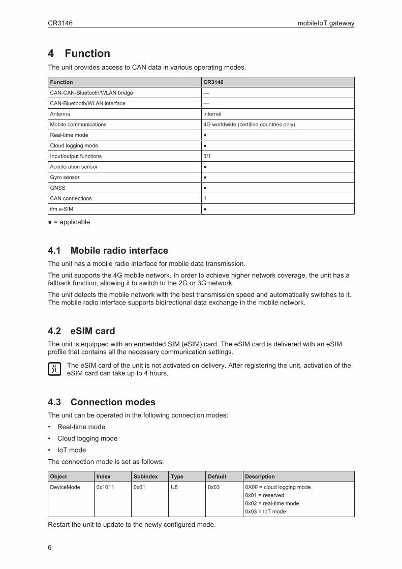
4 FunctionThe unit provides access to CAN data in various operating modes.
Function CR3146
CAN-CAN-Bluetooth/WLAN bridge —
CAN-Bluetooth/WLAN interface —
Antenna internal
Mobile communications 4G worldwide (certified countries only)
Real-time mode ●
Cloud logging mode ●
Input/output functions 3/1
Acceleration sensor ●
Gyro sensor ●
GNSS ●
CAN connections 1
ifm e-SIM ●
● = applicable
4.1 Mobile radio interfaceThe unit has a mobile radio interface for mobile data transmission.
The unit supports the 4G mobile network. In order to achieve higher network coverage, the unit has afallback function, allowing it to switch to the 2G or 3G network.
The unit detects the mobile network with the best transmission speed and automatically switches to it.The mobile radio interface supports bidirectional data exchange in the mobile network.
4.2 eSIM cardThe unit is equipped with an embedded SIM (eSIM) card. The eSIM card is delivered with an eSIMprofile that contains all the necessary communication settings.
The eSIM card of the unit is not activated on delivery. After registering the unit, activation of theeSIM card can take up to 4 hours.
4.3 Connection modesThe unit can be operated in the following connection modes:
• Real-time mode
• Cloud logging mode
• IoT mode
The connection mode is set as follows:
Object Index Subindex Type Default Description
DeviceMode 0x1011 0x01 U8 0x03 0X00 = cloud logging mode0x01 = reserved0x02 = real-time mode0x03 = IoT mode
Restart the unit to update to the newly configured mode.

mobileIoT gateway CR3146
7
When bit 7 is written, the unit restarts.
4.3.1 Real-time modeIn real-time mode, bidirectional transmission of CAN messages occurs.
The unit can send/receive process data (e.g. machine parameters) via CAN interfaces duringoperation via the mobile network and the mobileIoT platform. Depending on the design, it can transmitdata from the GNSS receiver and the input/output functions and forward them via the CAN bus.
The data is continuously transmitted and can be evaluated in near real-time. For this function, theremust be a permanent connection between the unit and the user software or the mobileIoT platform.
This mode also supports a real-time connection from Codesys 2.3. This requires appropriate softwareand a mobileIoT data contract.
The real-time mode can be set locally via an SDO or via the mobileIoT suite in the machine properties.
In real-time mode, no data or messages are stored on the mobileIoT platform.
4.3.2 Cloud logging modeIn cloud logging mode, selected CAN messages are sent to the cloud, processed and stored. In thiscase, the unit operates autonomously and does not have to be actively controlled by an application.
The configurations for this mode are made in the mobileIoT suite, which can send the data in CANmessages. An OTA (over-the-air) configuration of the units is carried out via the mobileIoT suite.
4.3.3 IoT modeThe IoT mode is a combination of real-time mode and cloud logging mode. It makes it possible toestablish a real-time connection with the CAN bus and automatically send GNSS position data to themobileIoT platform. In this mode, metrics are actively generated and sent by the application controller.Data linking to the application controller is configured in the mobileIoT suite. There the correspondingsource code will be automatically generated, which can be loaded into the controller programme.
No data is sent to the mobileIoT platform during real-time connection. As soon as the real-timeconnection is terminated, data is captured again and sent to the mobileIoT platform.
4.4 Input/output functionsThe unit has additional input/output functions (3 analogue inputs, 1 digital output). For example, theinput function can be used to collect device or machine status information or to directly detect andmonitor switch states. The data determined via the input/output functions can be visualised ortransferred via the CAN bus.
The input/output functions are accessed via the following objects:
Object Index Subindex Type Default Description
Analogue input 1 0x546F 0x14 R32ro
— Pin 4 of the 14-pin Micro Timer II connectorRaw value of the analogue input measure-ment (Volt)No filtering applied
Analogue input 2 0x546F 0x15 R32ro
— Pin 5 of the 14-pin Micro Timer II connectorRaw value of the analogue input measure-ment (Volt)No filtering applied
Analogue input 3 0x546F 0x16 R32ro
— Pin 6 of the 14-pin Micro Timer II connectorRaw value of the analogue input measure-ment (Volt)No filtering applied
GB

CR3146 mobileIoT gateway
8
Object Index Subindex Type Default Description
IO – clamp 30voltage
0x3333 0x67 R32ro
— Terminal 30Raw value of the analogue input measure-ment (Volt)
IO – clamp 15voltage
0x3333 0x66 R32ro
— Terminal 15Raw value of the analogue input measure-ment (Volt)
IO – clamp 15(ignition) state
0x3333 0x01 U8ro
— Terminal 150 = input signal low (< 2.5 V)1 = input signal high (> 5.5 V)
IO = digital out-put
0x3333 0x0F U8rw
— Pin 7 of the 14-pin Micro Timer II connectorBit 0: (0 = output signal low, 1 = output sig-nal high)Bits 1...7: reserved, set to 0
IO – digital out-put status
0x3333 0x10 U8 ro
— Pin 7 of the 14-pin Micro Timer II connectorBit 0: (0 = output signal error, 1 = output sig-nal OK)Bits 1...7: reserved, set to 0
IO – device tem-perature
0x3333 0x0E S16ro
— Device temperature in °C
The unit can send this data via the CAN interface. The configuration is made via the following objects:
Object Index Subindex Type Default Description
DeviceMode 0x4001 0x02 U8rw
— Bit 0: compatibility mode with unit CR3114(1 s cycle)Bit 1: forward device status via CAN bus (1 scycle)Bit 2: forward complete GNSS data via CANbus (1 s cycle)Bit 3: forward input/output data via CANbus (1 s cycle)Bit 4: forward acceleration and gyroscopedata via CAN bus (100 ms cycle)
IO BaseID 0x4005 0x07 U16 0x400 COB ID start address for input/output datatransmission (1s cycle)
The exact index and subindex can be found in the corresponding EDS file.
All data available in the respective device mode are sent via the CAN1 interface.
The data of the input/output functions are mapped to the following CAN messages:
COB ID Start byte Length(bytes) Type Object
IO BaseID + 0x00 0 4 R32 IO – clamp 30 voltage
4 4 R32 IO – clamp 15 voltage
IO BaseID + 0x01 0 4 R32 Analogue input 1
4 2 S32 IO – device temperature
4.5 Accelerometers and gyro sensorsThe accelerometers measure acceleration along the X, Y and Z axes. The 3-axis gyro sensordetermines the angular velocity on the X, Y and Z axes. This data is evaluated and can be forwardedto the controller via CAN bus.

mobileIoT gateway CR3146
9
The data of the acceleration/gyro sensors is accessed via the following objects:
Object Index Subindex Type Default Description
Acceleration – X-axis
0x544D 0x00 R32ro
— Current acceleration X-axis (unit: g)
Acceleration – Y-axis
0x544D 0x01 R32ro
— Current acceleration Y-axis (unit: g)
Acceleration – Z-axis
0x544D 0x02 R32ro
— Current acceleration Z-axis (unit: g)
Gyroscope – X-axis
0x544D 0x03 R32ro
— Current acceleration X-axis (unit: °/second)
Gyroscope – Y-axis
0x544D 0x04 R32ro
— Current acceleration Y-axis (unit: °/second)
Gyroscope – Z-axis
0x544D 0x05 R32ro
— Current acceleration Z-axis (unit: °/second)
The unit can send this data via the CAN interface. The configuration is made via the following objects:
Object Index Subindex Type Default Description
DeviceMode 0x4001 0x02 U8rw
— Bit 0: compatibility mode with unit CR3114(1 s cycle)Bit 1: forward device status via CAN bus (1 scycle)Bit 2: forward complete GNSS data via CANbus (1 s cycle)Bit 3: forward input/output data via CAN bus(1 s cycle)Bit 4: forward acceleration and gyro-scope data via CAN bus (100 ms cycle)
Movement Ba-seID
0x4005 0x05 U16 0x500 COB ID start address for acceleration andgyroscope data transmission (100 ms cycle)
All data available in the respective device mode are sent via the CAN1 interface.
The exact index and subindex can be found in the corresponding EDS file.
The acceleration and gyroscope data are mapped to the following CAN messages:
COB ID Start byte Length(bytes) Type Object
Movement BaseID +0x00
0 4 R32 Acceleration – X-axis
4 4 R32 Acceleration – Y-axis
Movement BaseID +0x01
0 4 R32 Acceleration – Z-axis
4 4 R32 Gyroscope – X-axis
Movement BaseID +0x02
0 4 R32 Gyroscope – Y-axis
0 4 R32 Gyroscope – Z-axis
GB

CR3146 mobileIoT gateway
10
4.6 GNSS (global navigation satellite system)The device has a GNSS receiver. The unit can forward the position data determined by the GNSSreceiver via the CAN bus or send it via the mobile network.
The device can evaluate signals from GPS, GLONASS and BeiDou satellites. Data from twonavigation systems can be evaluated simultaneously. This enhances the accuracy.
The GNSS data is accessed via the following objects:
Object Index Subindex Type Default Description
Positioning – an-tenna status
0x3333 0x13 U8ro
— 0 = antenna damaged or missing1 = antenna OK
Positioning – po-sition data valid
0x3333 0x14 U8ro
— 0 = position data invalid (no position detec-tion)1 = position data valid (position detection)
Positioning – ac-tive satellites
0x5220 0x00 U8ro
— Number of currently active satellites
Positioning –mode (GNSS)
0x5200 0x00 U8rw
— 0 = GPS only1 = GPS + GLONASS2 = GPS + BEIDOU3 = GLONASS + BEIDOU
Positioning – lon-gitude
0x5208 0x00 R32ro
— Longitude as a 32-bit floating point number(decimal degrees)
Positioning – lati-tude
0x5209 0x00 R32ro
— Latitude as a 32-bit floating point number(decimal degrees)
Positioning – alti-tude
0x520A 0x00 R32ro
— Height above mean sea level as a 32-bitfloat (in mm)
Positioning –speed overground
0x520B 0x00 R32ro
— Speed over ground as a 32-bit float (in m/s)
Positioning –GPS odometer
0x520B 0x02 U32ro
— Total GNSS based distance as a 32-bit un-signed integer (100 metres per bit)
Positioning – trig-ger distance forGPS odometer
0x520B 0x03 R32ro
— Distance in metres that the unit has to bemoved to start the odometer count
Positioning –heading
0x520C 0x00 R32ro
— Course with respect to north as a 32-bit float(decimal degrees)
Logging – cur-rent GNSS posi-tion
0x5200 0xF0 U8rw
— If this object is set to any value other than 0,recording of the unit’s current GNSS positionstarts.If the unit has no GNSS reference point, itwaits for a reference point before logging theposition.The flag remains on the written value untilthe position has been recorded. It is then re-set to 0.
The unit can send this data via the CAN interface. The configuration is made via the following objects:
Object Index Subindex Type Default Description
DeviceMode 0x4001 0x02 U8rw
— Bit 0: compatibility mode with unit CR3114(1 s cycle)Bit 1: forward device status via CAN bus (1 scycle)Bit 2: forward complete GNSS data viaCAN bus (1 s cycle)Bit 3: forward input/output data via CAN bus(1 s cycle)Bit 4: forward acceleration and gyroscopedata via CAN bus (100 ms cycle)

mobileIoT gateway CR3146
11
Object Index Subindex Type Default Description
Position BaseID 0x4005 0x06 U16 0x300 COB ID start address for input GNSS datatransmission (1s cycle)
All data available in the respective device mode are sent via the CAN1 interface.
The exact index and subindex can be found in the corresponding EDS file.
The GNSS data is mapped to the following CAN messages:
COB ID Start byte Length(bytes) Type Object
Position BaseID +0x00
0 1 U8 Positioning – position data valid
1 1 U8 Positioning – active satellites
2 1 U8 Positioning – mode (GNSS)
Position BaseID +0x01
0 4 R32 Positioning – longitude
4 4 R32 Positioning – latitude
Position BaseID +0x02
0 4 R32 Positioning – altitude
0 4 R32 Positioning – heading
Position BaseID +0x03
0 4 R32 Positioning – speed over ground
4 4 R32 Positioning – GPS odometer
4.6.1 Automatically send GNSS data to the mobileIoT platformThe device can automatically determine the GNSS position and send it to the mobileIoT platform.
The configuration is made via the following objects:
Object Index Subindex Type Default Description
GNSS-interval 0x4009 0x02 U32rw
900,000 Interval of the GNSS position logging (inms). Set to 0xFFFFFF to deactivate thisfunction. Min. value = 60,000
GNSS-distance 0x4009 0x03 U32rw
0xFFFFFFFF Distance between the most recent positiondetermined and the current position (lineardistance). The minimum distance is 3 me-tres.
Logging – file up-load period
0x3333 0x1C U16 0x01 Period in minutes. When this time haselapsed, the logged file is closed and trans-mitted to the server.Set this value to 0 to deactivate the period.
All data available in the respective device mode are sent via the CAN1 interface.
The exact index and subindex can be found in the corresponding EDS file.
4.7 Energy managementDifferent energy modes control the energy consumption of the unit. In addition to the standard mode,the unit also features a sleep mode. In this mode, some functions are deactivated to save energy.Specific events cause the unit to return to the standard mode.
No mobile radio connection is possible in sleep mode.
GB

CR3146 mobileIoT gateway
12
Energy management is accessed via the following objects:
Object Index Subindex Type Default Description
Power manage-ment – deepsleep flag
0x3333 0xF3 U8wo
— If this flag is set, the unit can only be wokenup from sleep mode via clamp 30, clamp 15or CAN1.The unit will not make up from sleep modecyclically or on a vibration event.Use e.g. during transportu Set this flag before changing to sleep
mode.
Power manage-ment – time tosleep
0x3333 0x08 U8wo
— Time in seconds until switching to sleepmode.The unit only changes to sleep mode ifclamp 15 is set to low and no CAN messageis present at the corresponding CAN inter-face.A CAN message can wake the unit fromsleep mode.Depending on the device design, a levelchange at clamp 15 or the detection of acertain acceleration force can wake the unitfrom sleep mode.With this setting, CAN messages are sent ifclamp 15 is set to high.
Power manage-ment – sleep tim-er status
0x3333 0x29 U8ro
— 0: sleep timer deactivated1: sleep timer activatedThe object can be read if clamp 15 is set tohigh.
Power manage-ment – shutdowndelay time
0x3333 0x32 U16rw
— Delay time in secondsAfter detecting the ignition input (clamp 15)and the CAN off state, the unit continues tooperate for the specified time and then goesto sleep mode.
Power manage-ment – cyclicwake-up time
0x3333 0x35 U32rw
— Time in secondsAfter the specified time period in sleepmode, the unit automatically wakes up andchanges to standard mode.This function is only active with a value > 0.
Power manage-ment – accel.wake-up force
0x3333 0x36 R32rw
— Force in gIf the accelerometer detects an accelerationforce greater than this value, the unit wakesup and changes to standard mode.This function is only active with a value > 0.
Power manage-ment - CANsleep time
0x3333 0x41 U32rw
— Time in millisecondsIf the unit does not receive any CAN mes-sages within the specified time period, itchanges to sleep mode.This function is only active with a value > 0.
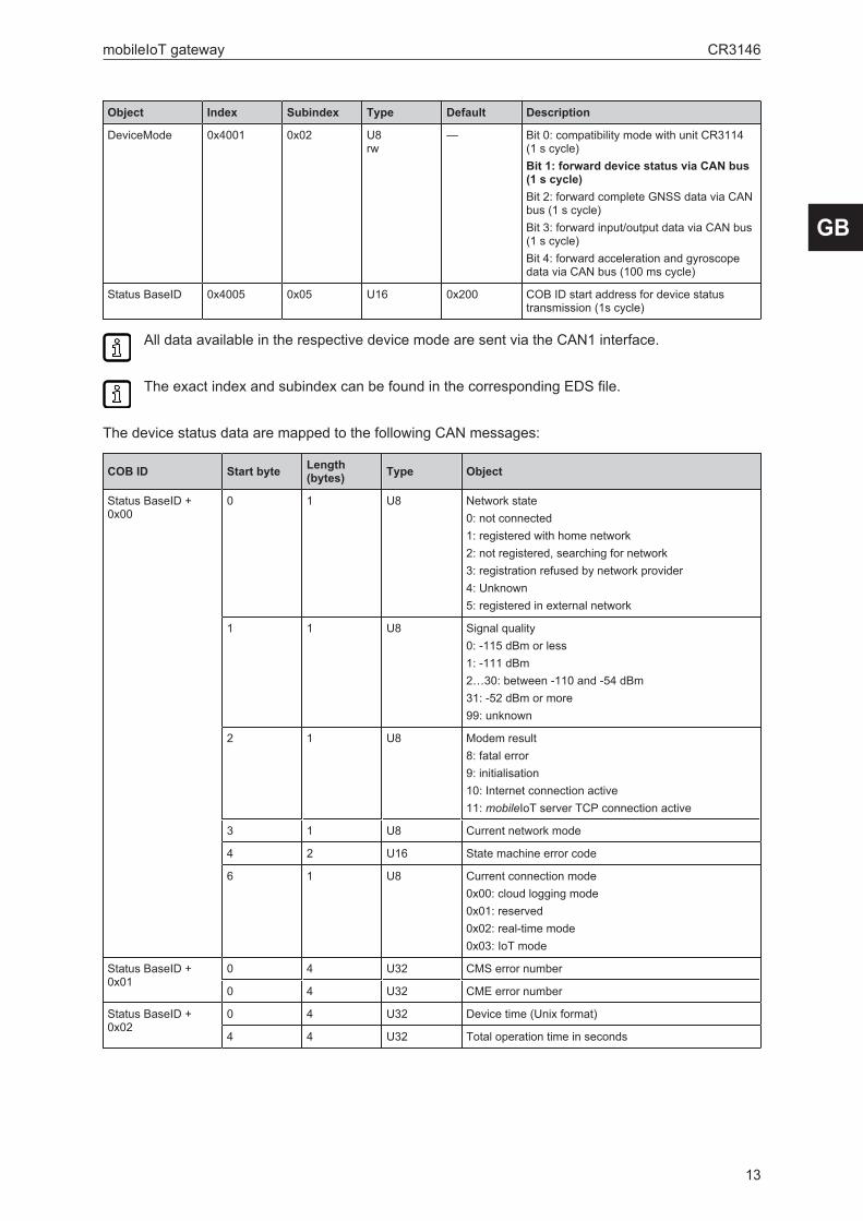
4.8 Device statusThe unit can send this data via the CAN interface. The configuration is made via the following objects:
mobileIoT gateway CR3146
13
Object Index Subindex Type Default Description
DeviceMode 0x4001 0x02 U8rw
— Bit 0: compatibility mode with unit CR3114(1 s cycle)Bit 1: forward device status via CAN bus(1 s cycle)Bit 2: forward complete GNSS data via CANbus (1 s cycle)Bit 3: forward input/output data via CAN bus(1 s cycle)Bit 4: forward acceleration and gyroscopedata via CAN bus (100 ms cycle)
Status BaseID 0x4005 0x05 U16 0x200 COB ID start address for device statustransmission (1s cycle)
All data available in the respective device mode are sent via the CAN1 interface.
The exact index and subindex can be found in the corresponding EDS file.
The device status data are mapped to the following CAN messages:
COB ID Start byte Length(bytes) Type Object
Status BaseID +0x00
0 1 U8 Network state0: not connected1: registered with home network2: not registered, searching for network3: registration refused by network provider4: Unknown5: registered in external network
1 1 U8 Signal quality0: -115 dBm or less1: -111 dBm2…30: between -110 and -54 dBm31: -52 dBm or more99: unknown
2 1 U8 Modem result8: fatal error9: initialisation10: Internet connection active11: mobileIoT server TCP connection active
3 1 U8 Current network mode
4 2 U16 State machine error code
6 1 U8 Current connection mode0x00: cloud logging mode0x01: reserved0x02: real-time mode0x03: IoT mode
Status BaseID +0x01
0 4 U32 CMS error number
0 4 U32 CME error number
Status BaseID +0x02
0 4 U32 Device time (Unix format)
4 4 U32 Total operation time in seconds
GB

CR3146 mobileIoT gateway
14
4.9 Compatibility modeIn compatibility mode, the unit transmits the data via the CAN bus in the same way as the CR3114unit.
The compatibility mode data is mapped to the following CAN messages:
COB ID Start byte Length(bytes) Type Object
0x180 + NodeID 0 1 U8 Network state0: not connected1: registered with home network2: not registered, searching for network3: registration refused by network provider4: Unknown5: registered in external network
1 1 U8 Signal quality0: -115 dBm or less1: -111 dBm2…30: between -110 and -54 dBm31: -52 dBm or more99: unknown
2 1 U8 Modem result8: fatal error9: initialisation10: Internet connection active11: mobileIoT server TCP connection active
3 1 U8 File transfer receive indication
4 1 U8 File transfer transmit command
5 1 U8 SMS transmit request
6 1 U8 SMS receive indication
7 1 U8 Device mode
Status BaseID +0x01
0 4 U32 GNSS – latitude
0 4 U32 GNSS – longitude
Status BaseID +0x02
0 4 U32 Fixed to 1
4 4 U32 Device time (Unix format)

mobileIoT gateway CR3146
15
5 Installationu Disconnect the power of the machine before installation.
The unit can be mounted in a horizontal position or with the connectors facing downwards.Installation with the connectors facing upwards is not permitted.
The unit must be fixed with the rear facing the mounting surface.
ATTENTIONHigher shock > IK07
w Damage possibleProtection rating and electrical protection might be impaired
u If necessary, the system creator must take external measures to protect the devicedepending on the requirements of the corresponding application.
u Replace damaged units, otherwise the technical data and safety will be impaired.
74
Fig. 1: Holes for mounting
u Use 2 M5x30 cylinder head bolts to fix the unit on an even surface.Tightening torque: 2.2 Nm
5.1 Mounting the antennasu When mounting the antennas in vehicles avoid the vicinity of fuel tanks, vessels with explosives or
insufficiently screened electronic components (→ 2 Safety instructions).
u Position the antennas so that a permanent distance of min. 0.2 m from people is ensured duringoperation.
u Do not install the antennas in closed metal constructions such as the driver's cab.
u To reliably receive the GPS signals, position the GPS antenna with unrestricted access to the sky.
u Please observe the antenna manufacturer’s notes.
Stable data transmission requires a good antenna signal. In case of problems change theposition of the antennas or the mobile equipment if necessary.
GB

CR3146 mobileIoT gateway
16
6 Electrical connection
6.1 Connectors
21
1: Micro Timer II connector, 14-pin(CAN, supply, inputs, outputs)
2: USB socket (Micro-AB type)
6.1.1 Operating voltage, CAN interface, inputs and outputs
1
2
13
14
Fig. 2: Micro Timer II connector, 14-pin1: VCC / clamp 30 (supply)2: Not connected3: GND / clamp 31 (supply)4: analogue input 15: analogue input 26: analogue input 37: digital output8: digital output / clamp 15 (input, ignition signal)9: Not connected10: Not connected11: Not connected12: Not connected13: CAN1_H (CAN interface 1 (high) bidirectional)14: CAN1_L (CAN interface 1 (low) bidirectional)
6.1.2 USB connectionThe USB connection (Micro-AB) is used for diagnostics and updates of the bootloader and firmware.
Protection rating IP6K7 is also guaranteed without the connected USB cable.
Always protect the USB connection with the matching protective plug to prevent soiling.

mobileIoT gateway CR3146
17
7 Light indicators21
1: ON LED2: STATUS LED
7.1 ON LEDThe ON LED indicates the status of the power supply.
Colour State Meaning
- Off Unit switched off or in sleep mode
Green On Unit switched on, clamp 30 voltage in permissible range
Red On Unit switched on, clamp 30 voltage outside the permissi-ble range or unit in battery mode
Green Flashing Unit in diagnostic or update mode
Tab. 1: ON LED
7.2 STATUS LEDThe STATUS LED indicates the operating status of the active connections. The different colours aredisplayed according to priority, from 5 (low) to 1 (high). If several operating states are active at thesame time, the STATUS LED always indicates the state with the highest priority.
Colour State Connect Priority Meaning
- Off - - If ON LED is also off:The unit is switched off.
Green On Various - Connected with the ifm mobileIoT server.
Blue On Mobile radio / Inter-net
1 Not connected with the ifm mobileIoT server.
Orange On CAN1 2 Connection faulty.
Red On CAN2 3 Connection faulty.
Magenta On GNSS 4 No position/antenna detected.
- Off Bluetooth/WLAN 5 Not connected to a network/device.
Tab. 2: STATUS LED
GB

CR3146 mobileIoT gateway
18
7.3 Indication of the operating modesLED State Meaning
ON A configuration update is carried out via the CAN inter-face.
STATUS
ON Active file transfer in logging mode. A configured CANmessage is received (orange flashing) and sent to theifm mobileIoT data portal (blue flashing).STATUS
ON Active data transfer in real-time mode.
STATUS
ON Initialisation after power on.
STATUS
ON A configuration update is carried out via the ifm mobileI-oT data portal.
STATUS
ON A remote firmware update is carried out via the ifm mo-bileIoT data portal.
STATUS
ON Reset of the unit via the slide switch on the D-Sub con-nector (CAN1).
STATUS
ON Reset (0x1011 0x64) of the unit via CAN.
STATUS
ON Transmission of the GPS position and the keepalivemessage. Display varies depending on the configuredpolling interval.STATUS
Tab. 3: Operating modes
mobileIoT gateway CR3146
19
8 Set-up
8.1 Necessary componentsThe following components are needed to configure and set up the device:
• Hardware
– CR3146
– suitable antennas / combined antenna for navigation and mobile radio
– connection cable
– voltage supply 8…32 V DC
– PC
– for further configuration (optional):
CAN/PC interface (e.g. CAN/RS232 USB interface CANfox, art. no.: EC2112) and adaptercable for CANfox (art. no.: EC2113)
CAN bus terminating resistors (2 x 120 Ω)
• ifm mobileIoT suiteTo register and activate the unit, access to the mobileIoT suite is required. You will receive theaccess data from your local ifm contact. The documentation for the mobileIoT suite and foractivating the unit can be found in the mobileIoT suite.After you have activated the unit, an mobileIoT data contract will be concluded.After successful registration and activation, the unit establishes a connection to theifm mobileIoT data portal and enables bidirectional data transfer.
• Configuration software
– ifm Maintenance Tool
– mobileIoT device configuration addin for ifm Maintenance Tool
For details on how to configure the unit, see the ifm Maintenance Tool documentation.
8.2 Connect the unitu Provide the CAN bus with 120 Ω terminating resistors.
u Connect the CAN/PC interface with the CAN adapter cable to the unit and connect it to the PC.
u Apply the supply voltage.
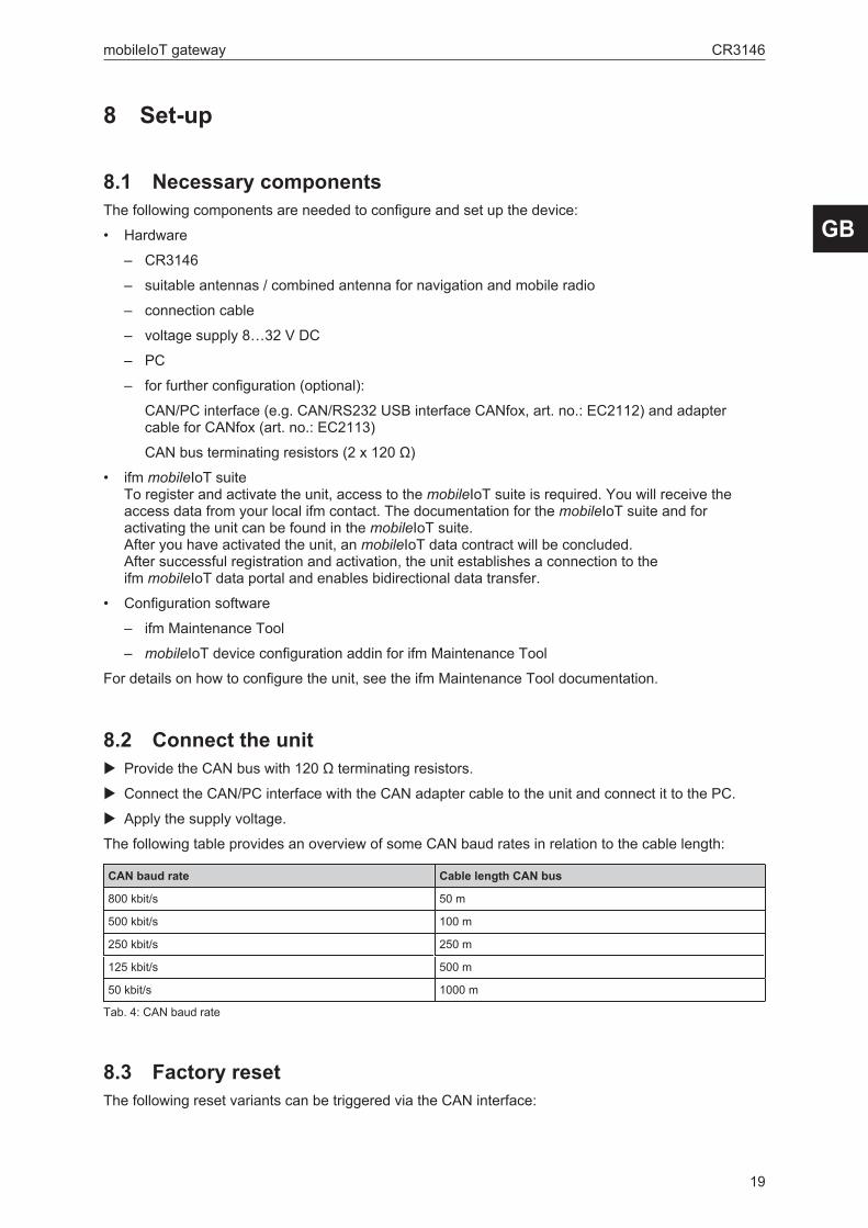
The following table provides an overview of some CAN baud rates in relation to the cable length:
CAN baud rate Cable length CAN bus
800 kbit/s 50 m
500 kbit/s 100 m
250 kbit/s 250 m
125 kbit/s 500 m
50 kbit/s 1000 m
Tab. 4: CAN baud rate
8.3 Factory resetThe following reset variants can be triggered via the CAN interface:
GB
CR3146 mobileIoT gateway
20
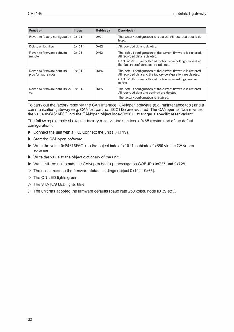
Function Index Subindex Description
Revert to factory configuration 0x1011 0x01 The factory configuration is restored. All recorded data is de-leted.
Delete all log files 0x1011 0x62 All recorded data is deleted.
Revert to firmware defaultsremote
0x1011 0x63 The default configuration of the current firmware is restored.All recorded data is deleted.CAN, WLAN, Bluetooth and mobile radio settings as well asthe factory configuration are retained.
Revert to firmware defaultsplus format remote
0x1011 0x64 The default configuration of the current firmware is restored.All recorded data and the factory configuration are deleted.CAN, WLAN, Bluetooth and mobile radio settings are re-tained.
Revert to firmware defaults lo-cal
0x1011 0x65 The default configuration of the current firmware is restored.All recorded data and settings are deleted.The factory configuration is retained.
To carry out the factory reset via the CAN interface, CANopen software (e.g. maintenance tool) and acommunication gateway (e.g. CANfox, part no. EC2112) are required. The CANopen software writesthe value 0x64616F6C into the CANopen object index 0x1011 to trigger a specific reset variant.
The following example shows the factory reset via the sub-index 0x65 (restoration of the defaultconfiguration):
u Connect the unit with a PC. Connect the unit (Ò / 19).
u Start the CANopen software.
u Write the value 0x64616F6C into the object index 0x1011, subindex 0x650 via the CANopensoftware.
u Write the value to the object dictionary of the unit.
u Wait until the unit sends the CANopen boot-up message on COB-IDs 0x727 and 0x728.
w The unit is reset to the firmware default settings (object 0x1011 0x65).
w The ON LED lights green.
w The STATUS LED lights blue.
w The unit has adopted the firmware defaults (baud rate 250 kbit/s, node ID 39 etc.).

mobileIoT gateway CR3146
21
9 Repair, maintenance and disposalThe unit is maintenance-free.
u Contact ifm in case of malfunction.
u Do not open the housing as the unit does not contain any components which can be maintained bythe user. The unit must only be repaired by the manufacturer.
u Clean the device using a dry cloth.
u Dispose of the unit in accordance with the national environmental regulations.
GB

CR3146 mobileIoT gateway
22
GlossarymobileIoT data contract
Contract required for the mobile radioconnection between the mobileIoT gatewayand the mobileIoT server
mobileIoT data portalPortal that processes/applies the data
mobileIoT platformThe complete cloud solution includingbackend (mobileIoT server), infrastructure,frontend for the machine managementportal (mobileIoT suite) and data processingportal (mobileIoT data portal)
mobileIoT serverCloud server on which the metrics arestored and to which the mobileIoT gatewaysconnect
mobileIoT suiteMachine management portal