Embed Size (px)
Citation preview
Operating instructions
Gas condensing boilerFor users
Read carefully before use.
Logano plus GB402
6 72
0 64
2 92
8 (0
7/20
09) G
B
Introduction
IntroductionDear Customer,
Heat is our element – and has been now for more than 275 years. Right from the start, we invest all our energies and passion into developing individual solutions for you, so you feel comfortable in your home.
Whether heat, domestic hot water or ventilation, a product from Buderus will always provide you with highly efficient heating technology of proven quality that will reliably keep your home cosy for many years to come.
We manufacture in accordance with the state of the art and ensure that our products are efficiently matched to each other. In this endeavour, efficiency and environmental compatibility are our priorities.
Thank you for choosing a Buderus product – a choice that will give you not only efficient energy utilisation but also high levels of comfort and convenience. To ensure that you retain this level of excellence, please read the operating instructions carefully. If, contrary to expectations, problems arise, please contact your installer who will be happy to assist you.
Should your installer not be available, then contact our customer service that is available to you around the clock.
We hope you will enjoy your new Buderus product!
Your Buderus Team
Logano plus GB402 - Subject to technical modifications.2
Contents
Contents
1 Explanation of symbols and safety information . . . . . . . . . . . . . . . . . . . 41.1 Explanation of symbols . . . . . . . . . . . . . . . . . 41.2 Safety precautions . . . . . . . . . . . . . . . . . . . . . 4
2 Product information . . . . . . . . . . . . . . . . . . . . . 62.1 EU Declaration of Conformity . . . . . . . . . . . . 62.2 Intended use . . . . . . . . . . . . . . . . . . . . . . . . . . 62.3 Water quality (fill and top-up water) . . . . . . . 62.4 Disposal . . . . . . . . . . . . . . . . . . . . . . . . . . . . . 62.5 Product description . . . . . . . . . . . . . . . . . . . . 7
3 Operation . . . . . . . . . . . . . . . . . . . . . . . . . . . . . . . 83.1 User interface elements . . . . . . . . . . . . . . . . . 83.2 Setting temperatures . . . . . . . . . . . . . . . . . . . 93.2.1 Specifying the set DHW temperature . . . . . 93.2.2 Setting the boiler water temperature . . . . . 103.3 Showing values on the display . . . . . . . . . . 113.4 Manual mode (emergency mode) . . . . . . . . 113.5 Setting pump run-on time . . . . . . . . . . . . . . 12
4 Operating the heating system . . . . . . . . . . . . 134.1 Switching on the heating system . . . . . . . . 134.1.1 Starting the heating system
using the base controller (BC10) and the programming unit (RCxx) . . . . . . . 13
4.2 Shutting down the heating system . . . . . . . 144.2.1 Shutting down the heating system
via the control unit . . . . . . . . . . . . . . . . . . . . 144.2.2 Shutting down the heating system
in emergencies . . . . . . . . . . . . . . . . . . . . . . 144.3 Checking the operating pressure,
topping up the heating water and venting the system . . . . . . . . . . . . . . . . . . . 14
4.3.1 Checking the operating pressure . . . . . . . . 144.3.2 Topping up the heating water
and venting the system . . . . . . . . . . . . . . . . 15
5 Inspection and maintenance . . . . . . . . . . . . . 165.1 What makes regular maintenance
important? . . . . . . . . . . . . . . . . . . . . . . . . . . 165.2 Cleaning and care . . . . . . . . . . . . . . . . . . . . 16
6 Troubleshooting . . . . . . . . . . . . . . . . . . . . . . . . 176.1 Recognising the operating state
and resetting faults . . . . . . . . . . . . . . . . . . . 17
Guide to instructionsInstallation and maintenance should only be carried out by qualified contractors authorised by Buderus.
B Prior to commencing operation, carefully read the whole of these Logano plus operating instructions.
B Keep this manual safe for future reference.
Logano plus GB402 - Subject to technical modifications. 3
1 Explanation of symbols and safety information
1 Explanation of symbols and safety information
1.1 Explanation of symbols
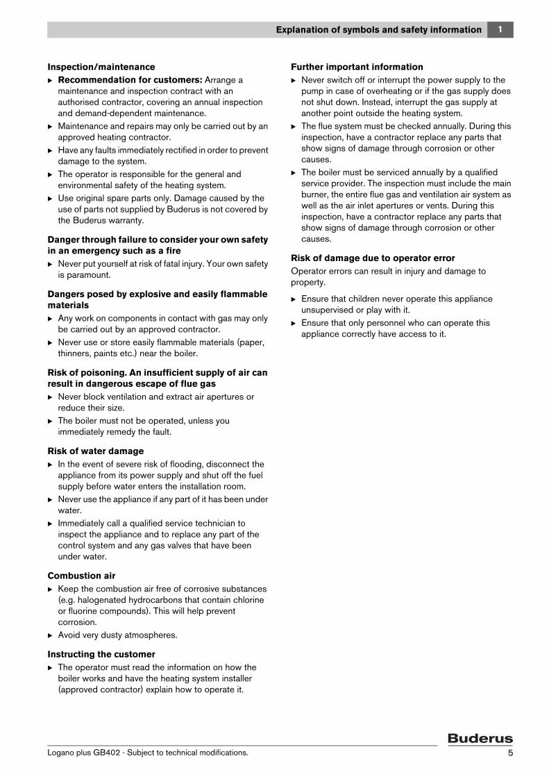
Warning symbols
Signal words indicate the seriousness of the hazard in terms of the consequences of not following the safety instructions.• NOTICE indicates possible damage to property or
equipment, but where there is no risk of injury.• CAUTION indicates possible injury.• WARNING indicates possible severe injury.• DANGER indicates possible risk to life.
Important information
Additional symbols
1.2 Safety precautions
If you smell gasB Close the gas tap.B Open windows and doors.B Do not operate electrical switches, including
telephones, plugs or doorbells.B Extinguish all naked flames. Do not smoke! Do not use
lighters.B Warn all occupants of the building, but do not ring
doorbells.B If you can actually hear gas escaping, leave the building
immediately. Prevent others from entering and notify the police and fire services from outside the building.
B From outside the building, call your gas supply utility and approved contractor.
If you smell flue gasB Switch off the boiler ( page 14).B Open windows and doors.B Notify an authorised contractor.
Installation, conversionB Correct and proper installation and adjustment of the
burner and the control unit are the fundamental requirements for safe and economical operation of the boiler.
B The boiler may only be installed or converted by an approved heating contractor.
B Never change any parts in contact with flue gas.B Do not cover or reduce the size of ventilation apertures
in doors, windows and walls. If draught-proof windows are fitted, ensure there is an adequate supply of combustion air.
B The DHW cylinder may only be used for heating domestic hot water.
B Never shut off safety valves! Water is expelled from the heating circuit and DHW circuit safety valve during heat-up.
Safety instructions in this document are framed and identified by a warning triangle which is printed on a grey background.
Electrical hazards are identified by a lightning symbol surrounded by a warning triangle.
Notes contain important information in cases where there is no risk of personal injury or material losses and are identified by the symbol shown on the left. They are bordered by horizontal lines above and below the text.
Symbol Meaning
B a step in an action sequence
a reference to a related part in the document or to other related documents
• a list entry
– a list entry (second level)
Tab. 1
Logano plus GB402 - Subject to technical modifications.4
1 Explanation of symbols and safety information
Inspection/maintenanceB Recommendation for customers: Arrange a
maintenance and inspection contract with an authorised contractor, covering an annual inspection and demand-dependent maintenance.
B Maintenance and repairs may only be carried out by an approved heating contractor.
B Have any faults immediately rectified in order to prevent damage to the system.
B The operator is responsible for the general and environmental safety of the heating system.
B Use original spare parts only. Damage caused by the use of parts not supplied by Buderus is not covered by the Buderus warranty.
Danger through failure to consider your own safety in an emergency such as a fireB Never put yourself at risk of fatal injury. Your own safety
is paramount.
Dangers posed by explosive and easily flammable materialsB Any work on components in contact with gas may only
be carried out by an approved contractor.B Never use or store easily flammable materials (paper,
thinners, paints etc.) near the boiler.
Risk of poisoning. An insufficient supply of air can result in dangerous escape of flue gasB Never block ventilation and extract air apertures or
reduce their size.B The boiler must not be operated, unless you
immediately remedy the fault.
Risk of water damageB In the event of severe risk of flooding, disconnect the
appliance from its power supply and shut off the fuel supply before water enters the installation room.
B Never use the appliance if any part of it has been under water.
B Immediately call a qualified service technician to inspect the appliance and to replace any part of the control system and any gas valves that have been under water.
Combustion airB Keep the combustion air free of corrosive substances
(e.g. halogenated hydrocarbons that contain chlorine or fluorine compounds). This will help prevent corrosion.
B Avoid very dusty atmospheres.
Instructing the customerB The operator must read the information on how the
boiler works and have the heating system installer (approved contractor) explain how to operate it.
Further important informationB Never switch off or interrupt the power supply to the
pump in case of overheating or if the gas supply does not shut down. Instead, interrupt the gas supply at another point outside the heating system.
B The flue system must be checked annually. During this inspection, have a contractor replace any parts that show signs of damage through corrosion or other causes.
B The boiler must be serviced annually by a qualified service provider. The inspection must include the main burner, the entire flue gas and ventilation air system as well as the air inlet apertures or vents. During this inspection, have a contractor replace any parts that show signs of damage through corrosion or other causes.
Risk of damage due to operator errorOperator errors can result in injury and damage to property.
B Ensure that children never operate this appliance unsupervised or play with it.
B Ensure that only personnel who can operate this appliance correctly have access to it.
Logano plus GB402 - Subject to technical modifications. 5
2 Product information
2 Product informationTo ensure safe, economical and environmentally responsible use of the heating system, we recommend that you read the safety instructions and operating instructions carefully.
These instructions provide the operator of the heating system with an overview of the use and operation of the boiler.
2.1 EU Declaration of ConformityThe design and operation of this product conform to the European Directives and the supplementary national requirements. Its conformity is demonstrated by the CE designation. You can call up the Declaration of Conformity for this product on the internet at www.buderus.de/konfo or request a copy from your local Buderus sales office.
2.2 Intended useThe Logano plus GB402 is designed for conventional use as a gas condensing boiler for DHW and central heating.
The boiler can be equipped with a programming unit, e.g. RC35 (available separately).
2.3 Water quality (fill and top-up water)For information regarding the water quality, see the enclosed operator's log “Water quality requirements for heat sources made from aluminium”.
2.4 DisposalB Dispose of boiler packaging in an environmentally
responsible manner.B All heating system components that have to be
replaced should be disposed of in an environmentally responsible manner at an authorised disposal site.
Logano plus GB402 - Subject to technical modifications.6
2 Product information
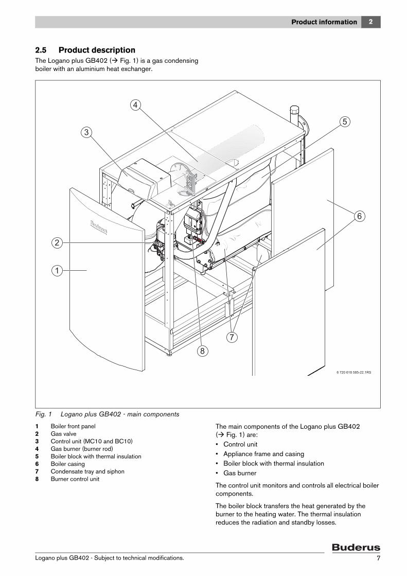
2.5 Product descriptionThe Logano plus GB402 ( Fig. 1) is a gas condensing boiler with an aluminium heat exchanger.
Fig. 1 Logano plus GB402 - main components
1 Boiler front panel2 Gas valve3 Control unit (MC10 and BC10)4 Gas burner (burner rod)5 Boiler block with thermal insulation6 Boiler casing7 Condensate tray and siphon8 Burner control unit
The main components of the Logano plus GB402 ( Fig. 1) are:• Control unit• Appliance frame and casing• Boiler block with thermal insulation• Gas burner
The control unit monitors and controls all electrical boiler components.
The boiler block transfers the heat generated by the burner to the heating water. The thermal insulation reduces the radiation and standby losses.
Logano plus GB402 - Subject to technical modifications. 7
3 Operation
3 Operation
3.1 User interface elementsThe base controller (BC10) is located behind the control unit fascia and enables standard operation of the heating system or the Logano plus GB402 boiler.
B To access the user interface of the base controller, flip up the control unit fascia.
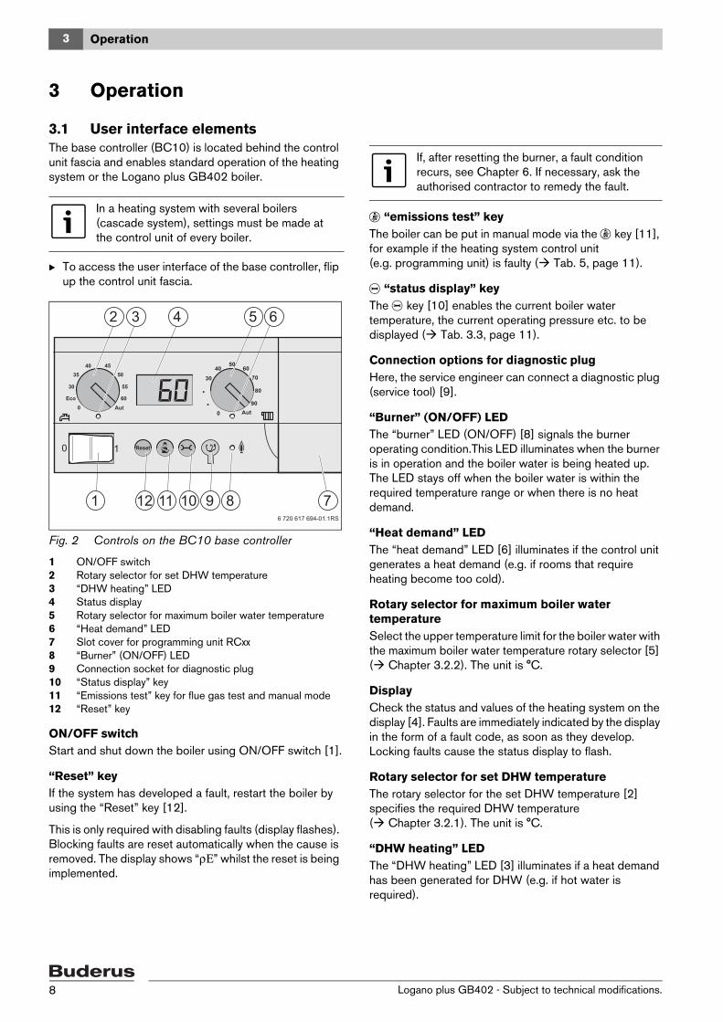
Fig. 2 Controls on the BC10 base controller
1 ON/OFF switch2 Rotary selector for set DHW temperature3 “DHW heating” LED4 Status display 5 Rotary selector for maximum boiler water temperature6 “Heat demand” LED7 Slot cover for programming unit RCxx8 “Burner” (ON/OFF) LED9 Connection socket for diagnostic plug10 “Status display” key11 “Emissions test” key for flue gas test and manual mode12 “Reset” key
ON/OFF switchStart and shut down the boiler using ON/OFF switch [1].
“Reset” keyIf the system has developed a fault, restart the boiler by using the “Reset” key [12].
This is only required with disabling faults (display flashes). Blocking faults are reset automatically when the cause is removed. The display shows “ρΕ” whilst the reset is being implemented.
d “emissions test” keyThe boiler can be put in manual mode via the d key [11], for example if the heating system control unit (e.g. programming unit) is faulty ( Tab. 5, page 11).
e “status display” keyThe e key [10] enables the current boiler water temperature, the current operating pressure etc. to be displayed ( Tab. 3.3, page 11).
Connection options for diagnostic plug Here, the service engineer can connect a diagnostic plug (service tool) [9].
“Burner” (ON/OFF) LEDThe “burner” LED (ON/OFF) [8] signals the burner operating condition.This LED illuminates when the burner is in operation and the boiler water is being heated up. The LED stays off when the boiler water is within the required temperature range or when there is no heat demand.
“Heat demand” LEDThe “heat demand” LED [6] illuminates if the control unit generates a heat demand (e.g. if rooms that require heating become too cold).
Rotary selector for maximum boiler water temperatureSelect the upper temperature limit for the boiler water with the maximum boiler water temperature rotary selector [5] ( Chapter 3.2.2). The unit is °C.
DisplayCheck the status and values of the heating system on the display [4]. Faults are immediately indicated by the display in the form of a fault code, as soon as they develop. Locking faults cause the status display to flash.
Rotary selector for set DHW temperatureThe rotary selector for the set DHW temperature [2] specifies the required DHW temperature ( Chapter 3.2.1). The unit is °C.
“DHW heating” LEDThe “DHW heating” LED [3] illuminates if a heat demand has been generated for DHW (e.g. if hot water is required).
In a heating system with several boilers (cascade system), settings must be made at the control unit of every boiler.
6 720 617 694-01.1RS
1
2 3 4 5 6
12 11 10 9 8 7
If, after resetting the burner, a fault condition recurs, see Chapter 6. If necessary, ask the authorised contractor to remedy the fault.
Logano plus GB402 - Subject to technical modifications.8
3 Operation
3.2 Setting temperatures
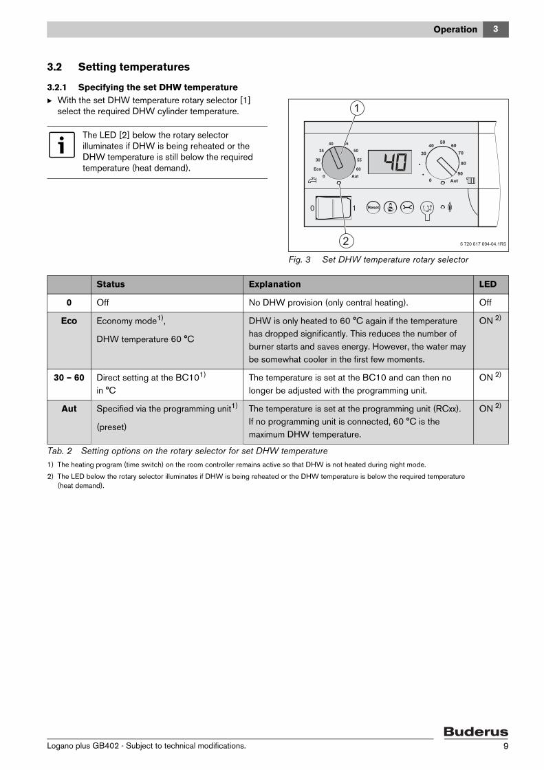
3.2.1 Specifying the set DHW temperatureB With the set DHW temperature rotary selector [1]
select the required DHW cylinder temperature.
Fig. 3 Set DHW temperature rotary selector
The LED [2] below the rotary selector illuminates if DHW is being reheated or the DHW temperature is still below the required temperature (heat demand).
6 720 617 694-04.1RS
1
2
Status Explanation LED
0 Off No DHW provision (only central heating). Off
Eco Economy mode1),
DHW temperature 60 °C
DHW is only heated to 60 °C again if the temperature has dropped significantly. This reduces the number of burner starts and saves energy. However, the water may be somewhat cooler in the first few moments.
ON 2)
30 – 60 Direct setting at the BC101)
in °CThe temperature is set at the BC10 and can then no longer be adjusted with the programming unit.
ON 2)
Aut Specified via the programming unit1)
(preset)
The temperature is set at the programming unit (RCxx). If no programming unit is connected, 60 °C is the maximum DHW temperature.
ON 2)
Tab. 2 Setting options on the rotary selector for set DHW temperature1) The heating program (time switch) on the room controller remains active so that DHW is not heated during night mode.
2) The LED below the rotary selector illuminates if DHW is being reheated or the DHW temperature is below the required temperature (heat demand).
Logano plus GB402 - Subject to technical modifications. 9
3 Operation
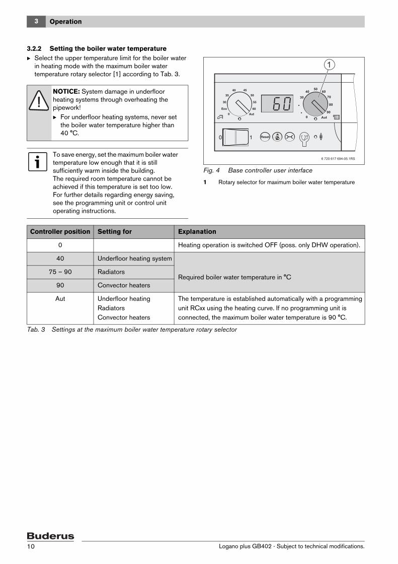
3.2.2 Setting the boiler water temperatureB Select the upper temperature limit for the boiler water
in heating mode with the maximum boiler water temperature rotary selector [1] according to Tab. 3.
Fig. 4 Base controller user interface
1 Rotary selector for maximum boiler water temperature
NOTICE: System damage in underfloor heating systems through overheating the pipework!B For underfloor heating systems, never set
the boiler water temperature higher than 40 °C.
To save energy, set the maximum boiler water temperature low enough that it is still sufficiently warm inside the building.The required room temperature cannot be achieved if this temperature is set too low.For further details regarding energy saving, see the programming unit or control unit operating instructions.
6 720 617 694-05.1RS
1
Controller position Setting for Explanation
0 Heating operation is switched OFF (poss. only DHW operation).
40 Underfloor heating system
Required boiler water temperature in °C75 – 90 Radiators
90 Convector heaters
Aut Underfloor heatingRadiatorsConvector heaters
The temperature is established automatically with a programming unit RCxx using the heating curve. If no programming unit is connected, the maximum boiler water temperature is 90 °C.
Tab. 3 Settings at the maximum boiler water temperature rotary selector
Logano plus GB402 - Subject to technical modifications.10
3 Operation
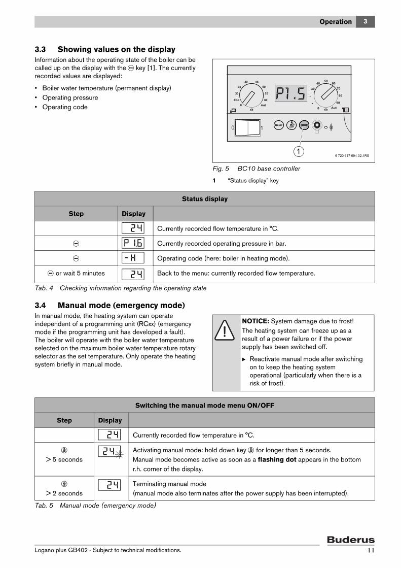
3.3 Showing values on the displayInformation about the operating state of the boiler can be called up on the display with the e key [1]. The currently recorded values are displayed:
• Boiler water temperature (permanent display)• Operating pressure• Operating code
Fig. 5 BC10 base controller
1 “Status display” key
3.4 Manual mode (emergency mode)In manual mode, the heating system can operate independent of a programming unit (RCxx) (emergency mode if the programming unit has developed a fault). The boiler will operate with the boiler water temperature selected on the maximum boiler water temperature rotary selector as the set temperature. Only operate the heating system briefly in manual mode.
6 720 617 694-02.1RS1
Status display
Step Display
[\/2/4| Currently recorded flow temperature in °C.
e [p/1.6| Currently recorded operating pressure in bar.
e [-/h/\| Operating code (here: boiler in heating mode).
e or wait 5 minutes [\/2/4| Back to the menu: currently recorded flow temperature.
Tab. 4 Checking information regarding the operating state
NOTICE: System damage due to frost!The heating system can freeze up as a result of a power failure or if the power supply has been switched off.
B Reactivate manual mode after switching on to keep the heating system operational (particularly when there is a risk of frost).
Switching the manual mode menu ON/OFF
Step Display
[\/2/4| Currently recorded flow temperature in °C.
d > 5 seconds
[/2/4} Activating manual mode: hold down key d for longer than 5 seconds.Manual mode becomes active as soon as a flashing dot appears in the bottom r.h. corner of the display.
d > 2 seconds
[\/2/4| Terminating manual mode(manual mode also terminates after the power supply has been interrupted).
Tab. 5 Manual mode (emergency mode)
Logano plus GB402 - Subject to technical modifications. 11
3 Operation
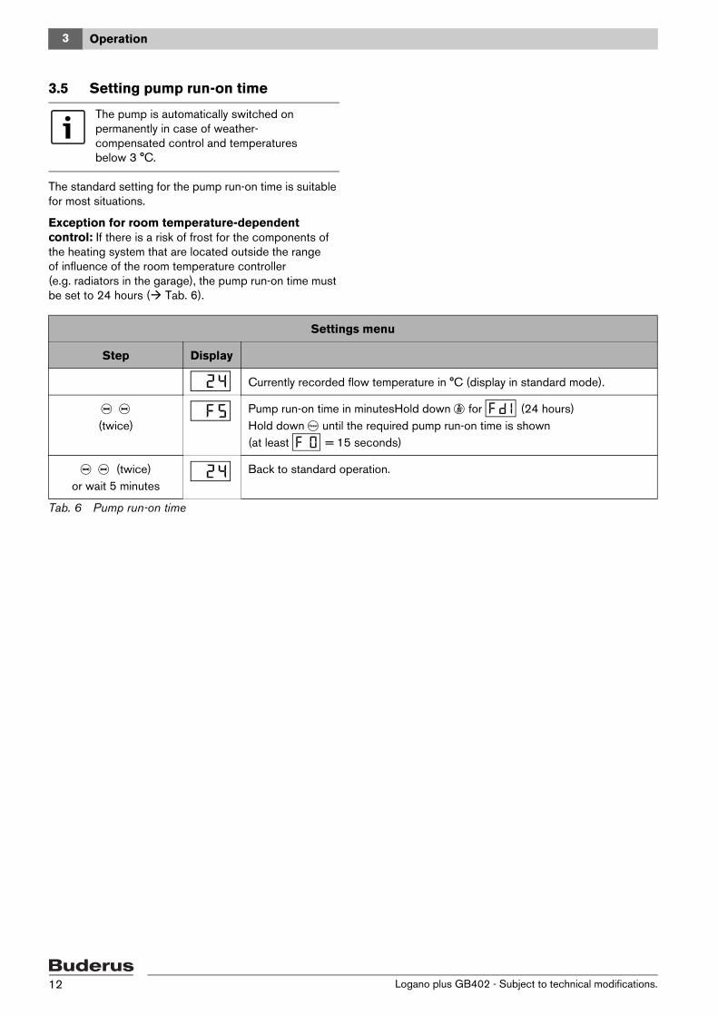
3.5 Setting pump run-on time
The standard setting for the pump run-on time is suitable for most situations.
Exception for room temperature-dependent control: If there is a risk of frost for the components of the heating system that are located outside the range of influence of the room temperature controller (e.g. radiators in the garage), the pump run-on time must be set to 24 hours ( Tab. 6).
The pump is automatically switched on permanently in case of weather-compensated control and temperatures below 3 °C.
Settings menu
Step Display
[\/2/4| Currently recorded flow temperature in °C (display in standard mode).
e e (twice)
[\/f/5| Pump run-on time in minutesHold down d for [f/d1| (24 hours)Hold down c until the required pump run-on time is shown(at least [f//0| = 15 seconds)
e e (twice) or wait 5 minutes
[\/2/4| Back to standard operation.
Tab. 6 Pump run-on time
Logano plus GB402 - Subject to technical modifications.12
4 Operating the heating system
4 Operating the heating system
4.1 Switching on the heating systemBefore switching the system on, check that:
• the operating pressure is high enough,• the fuel supply has been turned on at the main shut-off
valve, and• the heating system emergency stop switch is switched
on.
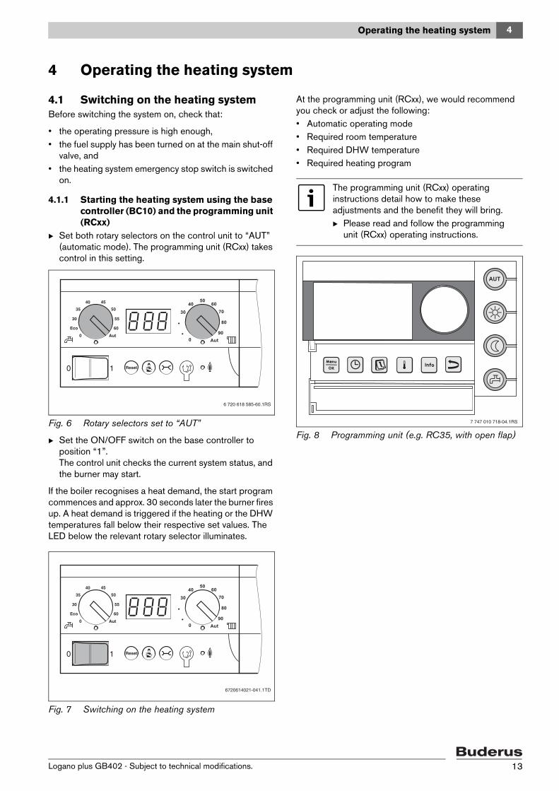
4.1.1 Starting the heating system using the base controller (BC10) and the programming unit (RCxx)
B Set both rotary selectors on the control unit to “AUT” (automatic mode). The programming unit (RCxx) takes control in this setting.
Fig. 6 Rotary selectors set to “AUT”
B Set the ON/OFF switch on the base controller to position “1”.The control unit checks the current system status, and the burner may start.
If the boiler recognises a heat demand, the start program commences and approx. 30 seconds later the burner fires up. A heat demand is triggered if the heating or the DHW temperatures fall below their respective set values. The LED below the relevant rotary selector illuminates.
Fig. 7 Switching on the heating system
At the programming unit (RCxx), we would recommend you check or adjust the following:• Automatic operating mode• Required room temperature• Required DHW temperature• Required heating program
Fig. 8 Programming unit (e.g. RC35, with open flap)
6 720 618 585-60.1RS
6720614021-041.1TD
The programming unit (RCxx) operating instructions detail how to make these adjustments and the benefit they will bring.B Please read and follow the programming
unit (RCxx) operating instructions.
7 747 010 718-04.1RS
Logano plus GB402 - Subject to technical modifications. 13
4 Operating the heating system
4.2 Shutting down the heating system
4.2.1 Shutting down the heating system via the control unit
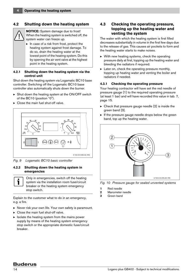
Shut down the heating system via Logamatic BC10 base controller. Switching off the Logamatic BC10 base controller also automatically shuts down the burner.
B Shut down the heating system at the ON/OFF switch of the BC10 (position “0”).
B Close the main fuel shut-off valve.
Fig. 9 Logamatic BC10 basic controller
4.2.2 Shutting down the heating system in emergencies
Explain to the customer what to do in an emergency, e.g. a fire.
B Never risk your own life. Your own safety is paramount.B Close the main fuel shut-off valve.B Isolate the heating system from the mains power
supply by means of the heating system emergency stop switch or the appropriate domestic fuse/circuit breaker.
4.3 Checking the operating pressure, topping up the heating water and venting the system
The water with which the heating system is first filled decreases substantially in volume in the first few days due to the release of gas. This causes air pockets to form and the heating water starts to make noises.
B With new heating systems, check the operating pressure daily at first, topping up the heating water and bleeding the radiators if required.
B Later on, check the operating pressure monthly, topping up heating water and venting the boiler and radiators if needed.
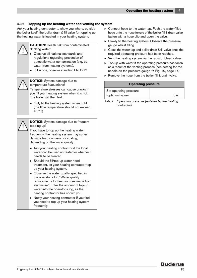
4.3.1 Checking the operating pressureYour heating contractor will have set the red needle of pressure gauge [1] to the required operating pressure (at least 1 bar) and will have recorded this value in tab. 7, page 15.
B Check that pressure gauge needle [2] is inside the green band [3].
B If the pressure gauge needle drops below the green band, top up the heating water.
Fig. 10 Pressure gauge for sealed unvented systems
1 Red needle2 Manometer needle3 Green band
NOTICE: System damage due to frost! When the heating system is switched off, the system water can freeze up.B In case of a risk from frost, protect the
heating system against frost damage. To do so, drain the heating water at the lowest point of the heating system. Do this by opening the air vent valve at the highest point in the heating system.
Only in emergencies, switch off the heating system via the installation room fuse/circuit breaker or the heating system emergency stop switch.
6 720 615 876-59.1RS
3
2
1
Logano plus GB402 - Subject to technical modifications.14
4 Operating the heating system
4.3.2 Topping up the heating water and venting the systemAsk your heating contractor to show you where, outside the boiler itself, the boiler drain & fill valve for topping up the heating water is located in your heating system.
B Connect hose to the water tap. Push the water-filled hose onto the hose ferrule of the boiler fill & drain valve, fasten with a hose clip and open the valve.
B Slowly fill the heating system. Observe the pressure gauge whilst filling.
B Close the water tap and boiler drain & fill valve once the required operating pressure has been reached.
B Vent the heating system via the radiator bleed valves.B Top up with water if the operating pressure has fallen
as a result of the venting process (see setting for red needle on the pressure gauge Fig. 10, page 14).
B Remove the hose from the boiler fill & drain valve.
CAUTION: Health risk from contaminated drinking water!B Observe all national standards and
regulations regarding prevention of domestic water contamination (e.g. by water from heating systems).
B In Europe, observe standard EN 1717.
NOTICE: System damage due to temperature fluctuations!Temperature stresses can cause cracks if you fill your heating system when it is hot. The boiler will then leak.
B Only fill the heating system when cold (the flow temperature should not exceed 40 °C).
NOTICE: System damage due to frequent topping up!If you have to top up the heating water frequently, the heating system may suffer damage from corrosion or scaling, depending on the water quality.
B Ask your heating contractor if the local water can be used untreated or whether it needs to be treated.
B Should the fill/top-up water need treatment, let your heating contractor top up your heating system.
B Observe the water quality specified in the operator's log “Water quality requirements for heat sources made from aluminium”. Enter the amount of top-up water into the operator's log, as the heating contractor has shown you.
B Notify your heating contractor if you find you need to top up your heating system frequently.
Operating pressure
Set operating pressure(optimum value) _____________ bar
Tab. 7 Operating pressure (entered by the heating contractor)
Logano plus GB402 - Subject to technical modifications. 15
5 Inspection and maintenance
5 Inspection and maintenance
5.1 What makes regular maintenance important?
Heating systems should be regularly serviced for the following reasons:
• to maintain a high level of efficiency and to operate the system economically (low fuel consumption),
• to achieve a high level of operational reliability,• to maintain the cleanest possible combustion.
5.2 Cleaning and careTo clean the boiler, wipe the casing with a damp cloth (soapy solution). Never use scouring or aggressive cleaning agents that would damage the painted surface or plastic components.
NOTICE: System damage through absence of or inadequate cleaning and maintenance!B Have your heating system inspected,
cleaned and serviced annually by a contractor.
B We recommend you enter a contract covering an annual inspection and service subject to demand.
Logano plus GB402 - Subject to technical modifications.16
6 Troubleshooting
6 Troubleshooting
6.1 Recognising the operating state and resetting faults
If a fault has developed, the fault code flashes on the control unit display. The programming unit shows faults as plain text messages.
A fault has developed if the display flashes and indicates something other than the current boiler water temperature or an operating message.
Example: “6A” = the burner will not start
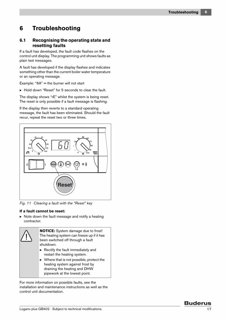
B Hold down “Reset” for 5 seconds to clear the fault.
The display shows “rE” whilst the system is being reset. The reset is only possible if a fault message is flashing.
If the display then reverts to a standard operating message, the fault has been eliminated. Should the fault recur, repeat the reset two or three times.
Fig. 11 Clearing a fault with the “Reset” key
If a fault cannot be reset:B Note down the fault message and notify a heating
contractor.
For more information on possible faults, see the installation and maintenance instructions as well as the control unit documentation.
NOTICE: System damage due to frost! The heating system can freeze up if it has been switched off through a fault shutdown.B Rectify the fault immediately and
restart the heating system.B Where that is not possible, protect the
heating system against frost by draining the heating and DHW pipework at the lowest point.
Logano plus GB402 - Subject to technical modifications. 17
6
Notes
Logano plus GB402 - Subject to technical modifications.18
6
Notes
Logano plus GB402 - Subject to technical modifications. 19

������������ ���� ������� ������� ��� ��������� �������� ���� ��� ���� ��!����� ��""�� ���� ��� ����#�$� �%��& '&�%�����()������(�(�*
+� !� ,- ��� +.� ������� �� � )���� ���� /���! !�����!��0� 1�(