Embed Size (px)
Citation preview

BA057D/06/en/12.05
71008475
Valid as of version
V 2.01.XX (device software)
Operating Instructions
Proline Promass 80
Coriolis Mass Flow Measuring System
6
Brief operating instructions Proline Promass 80
2 Endress+Hauser
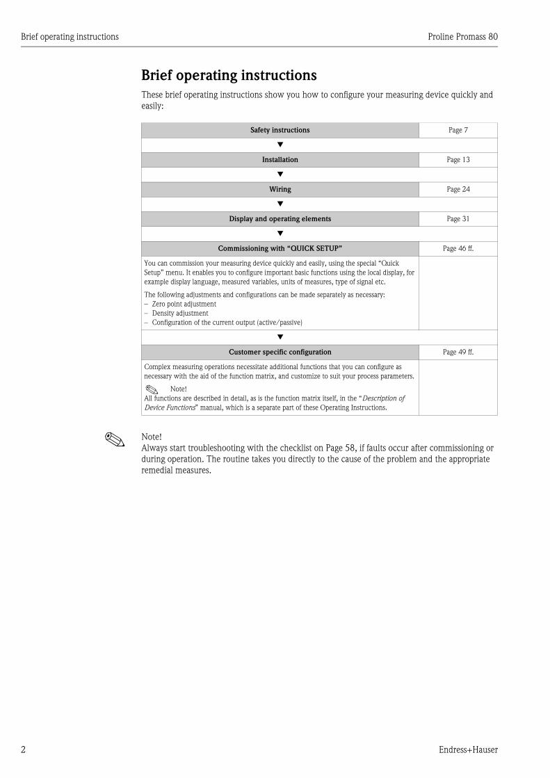
Brief operating instructions
These brief operating instructions show you how to configure your measuring device quickly and
easily:
! Note!
Always start troubleshooting with the checklist on Page 58, if faults occur after commissioning or
during operation. The routine takes you directly to the cause of the problem and the appropriate
remedial measures.
Safety instructions Page 7
Installation Page 13
Wiring Page 24
Display and operating elements Page 31
Commissioning with “QUICK SETUP” Page 46 ff.
You can commission your measuring device quickly and easily, using the special “Quick
Setup” menu. It enables you to configure important basic functions using the local display, for
example display language, measured variables, units of measures, type of signal etc.
The following adjustments and configurations can be made separately as necessary:
– Zero point adjustment
– Density adjustment
– Configuration of the current output (active/passive)
Customer specific configuration Page 49 ff.
Complex measuring operations necessitate additional functions that you can configure as
necessary with the aid of the function matrix, and customize to suit your process parameters.
! Note!
All functions are described in detail, as is the function matrix itself, in the “Description of
Device Functions” manual, which is a separate part of these Operating Instructions.
Proline Promass 80 Brief operating instructions
Endress+Hauser 3
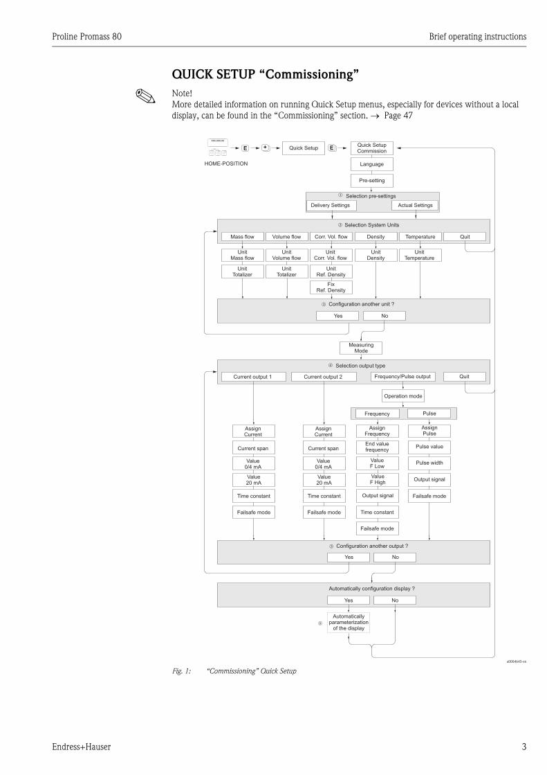
QUICK SETUP “Commissioning”
! Note!
More detailed information on running Quick Setup menus, especially for devices without a local
display, can be found in the “Commissioning” section. → Page 47
a0004645-en
Fig. 1: “Commissioning” Quick Setup
++ +E EEsc
E+-
XXX.XXX.XX
Yes
Yes
Yes
No
No
No
Mass flow
Current output 1
Volume flow Density
Frequency/Pulse output
Selection System Units
Selection output type
Configuration another unit ?
Configuration another output ?
Automatically configuration display ?
Temperature Quit
Quit
UnitMass flow
AssignCurrent
Current span
Value0/4 mA
Value20 mA
Time constant
Time constantFailsafe mode
Failsafe mode
Failsafe mode
AssignFrequency
End valuefrequency
ValueF Low
ValueF High
Output signal
AssignPulse
Pulse value
Pulse width
Output signal
UnitflowVolume
UnitDensity
Operation mode
UnitTemperature
MeasuringMode
UnitTotalizer
UnitTotalizer
Frequency Pulse
Automaticallyparameterization
of the display
Language
Pre-setting
Quick Setup
HOME-POSITION
Quick SetupCommission
AssignCurrent
Current span
Value0/4 mA
Value20 mA
Time constant
Failsafe mode
Current output 2
n
o
p
q
Corr. Vol. flow
UnitCorr. Vol. flow
UnitRef. Density
FixRef. Density
r
Selection pre-settings
Actual SettingsDeliver Settingsy
m

Brief operating instructions Proline Promass 80
4 Endress+Hauser
! Note!
• The display returns to the cell SETUP COMMISSIONING if you press the X key combination
during an interrogation. The stored parameters remain valid.
m Selecting DELIVERY SETTINGS returns each selected unit to the factory setting.
Selecting ACTUAL SETTINGS applies the units you have set previously.
n Only units not yet configured in the current Setup are offered for selection in each cycle. The unit for mass, volume
and corrected volume is derived from the corresponding flow unit.
o The YES option remains visible until all the units have been configured. NO is the only option displayed when no
further units are available.
p Only the outputs not yet configured in the current Setup are offered for selection in each cycle.
q The YES option remains visible until all the outputs have been configured. NO is the only option displayed when
no further outputs are available.
r The “automatic parameterization of the display” option contains the following basic settings/factory settings:
YES: line 1= mass flow; line 2 = totalizer 1;
information line = operating/system conditions
NO: The existing (selected) settings remain.

Proline Promass 80 Table of contents
Endress+Hauser 5
Table of contents
1 Safety instructions . . . . . . . . . . . . . . . . 7
1.1 Designated use . . . . . . . . . . . . . . . . . . . . . . . . . . . . 7
1.2 Installation, commissioning and operation . . . . . . . . 7
1.3 Operational safety . . . . . . . . . . . . . . . . . . . . . . . . . . 7
1.4 Return . . . . . . . . . . . . . . . . . . . . . . . . . . . . . . . . . . . 8
1.5 Notes on safety conventions and icons . . . . . . . . . . . 8
2 Identification . . . . . . . . . . . . . . . . . . . . 9
2.1 Device designation . . . . . . . . . . . . . . . . . . . . . . . . . 9
2.1.1 Nameplate of the transmitter . . . . . . . . . . . . 9
2.1.2 Nameplate of the sensor . . . . . . . . . . . . . . 10
2.1.3 Nameplate, connections . . . . . . . . . . . . . . 11
2.2 Certificates and approvals . . . . . . . . . . . . . . . . . . . 11
2.3 Registered trademarks . . . . . . . . . . . . . . . . . . . . . . 12
3 Installation . . . . . . . . . . . . . . . . . . . . . 13
3.1 Incoming acceptance, transport and storage . . . . . . 13
3.1.1 Incoming acceptance . . . . . . . . . . . . . . . . . 13
3.1.2 Transport . . . . . . . . . . . . . . . . . . . . . . . . . 13
3.1.3 Storage . . . . . . . . . . . . . . . . . . . . . . . . . . . 14
3.2 Installation conditions . . . . . . . . . . . . . . . . . . . . . . 14
3.2.1 Dimensions . . . . . . . . . . . . . . . . . . . . . . . . 14
3.2.2 Mounting location . . . . . . . . . . . . . . . . . . . 14
3.2.3 Orientation . . . . . . . . . . . . . . . . . . . . . . . . 16
3.2.4 Heating . . . . . . . . . . . . . . . . . . . . . . . . . . . 18
3.2.5 Thermal insulation . . . . . . . . . . . . . . . . . . 19
3.2.6 Inlet and outlet runs . . . . . . . . . . . . . . . . . 19
3.2.7 Vibrations . . . . . . . . . . . . . . . . . . . . . . . . . 19
3.2.8 Limiting flow . . . . . . . . . . . . . . . . . . . . . . . 19
3.3 Installation . . . . . . . . . . . . . . . . . . . . . . . . . . . . . . 20
3.3.1 Turning the transmitter housing . . . . . . . . 20
3.3.2 Installing the wall-mount
transmitter housing . . . . . . . . . . . . . . . . . . 21
3.3.3 Turning the local display . . . . . . . . . . . . . . 23
3.4 Post installation check . . . . . . . . . . . . . . . . . . . . . . 23
4 Wiring . . . . . . . . . . . . . . . . . . . . . . . . 24
4.1 Connecting the remote version . . . . . . . . . . . . . . . 24
4.1.1 Connecting the sensor/transmitter . . . . . . 24
4.1.2 Cable specification, connecting cable . . . . . 25
4.2 Connecting the measuring unit . . . . . . . . . . . . . . . 25
4.2.1 Transmitter connection . . . . . . . . . . . . . . . 25
4.2.2 Terminal assignment . . . . . . . . . . . . . . . . . 27
4.2.3 HART connection . . . . . . . . . . . . . . . . . . . 28
4.3 Degree of protection . . . . . . . . . . . . . . . . . . . . . . . 29
4.4 Post connection check . . . . . . . . . . . . . . . . . . . . . . 30
5 Operation . . . . . . . . . . . . . . . . . . . . . . 31
5.1 Display and operating elements . . . . . . . . . . . . . . . 31
5.2 Brief operating instructions to the function matrix . 32
5.2.1 General notes . . . . . . . . . . . . . . . . . . . . . . 33
5.2.2 Enabling the programming mode . . . . . . . . 33
5.2.3 Disabling the programming mode . . . . . . . 33
5.3 Error messages . . . . . . . . . . . . . . . . . . . . . . . . . . . . 34
5.3.1 Type of error . . . . . . . . . . . . . . . . . . . . . . . 34
5.3.2 Error message type . . . . . . . . . . . . . . . . . . . 34
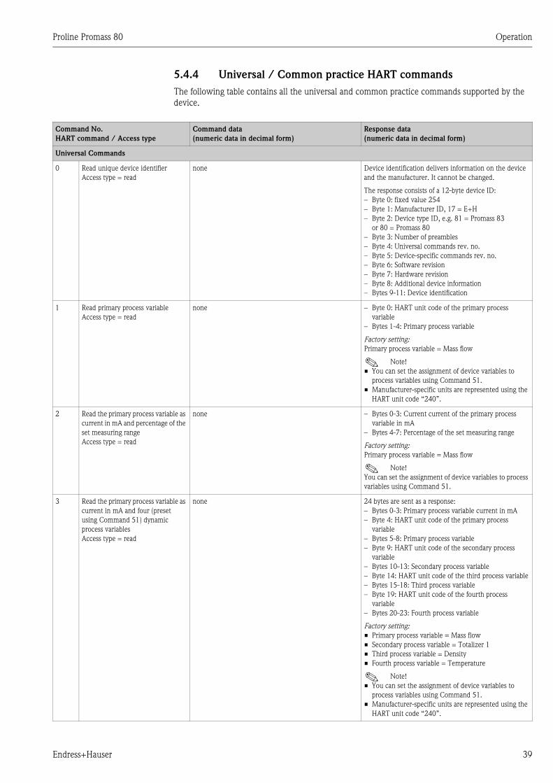
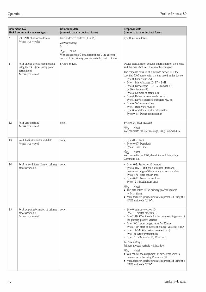
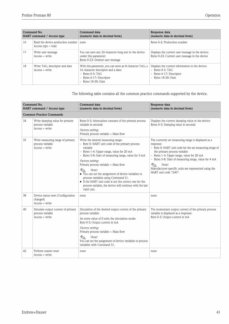
5.4 Communication . . . . . . . . . . . . . . . . . . . . . . . . . . . 35
5.4.1 Operating options . . . . . . . . . . . . . . . . . . . 36
5.4.2 Current device description files . . . . . . . . . 37
5.4.3 Device and process variables . . . . . . . . . . . 38
5.4.4 Universal / Common practice
HART commands . . . . . . . . . . . . . . . . . . . 39
5.4.5 Device status / Error messages . . . . . . . . . . 44
6 Commissioning . . . . . . . . . . . . . . . . . . 46
6.1 Function check . . . . . . . . . . . . . . . . . . . . . . . . . . . 46
6.2 Switching on the measuring device . . . . . . . . . . . . 46
6.3 Quick Setup . . . . . . . . . . . . . . . . . . . . . . . . . . . . . . 47
6.3.1 “Commissioning” Quick Setup . . . . . . . . . . 47
6.4 Configuration . . . . . . . . . . . . . . . . . . . . . . . . . . . . 49
6.4.1 One current output: active/passive . . . . . . 49
6.4.2 Two current outputs: active/passive . . . . . 50
6.5 Adjust . . . . . . . . . . . . . . . . . . . . . . . . . . . . . . . . . . 51
6.5.1 Zero point adjustment . . . . . . . . . . . . . . . . 51
6.5.2 Density adjustment . . . . . . . . . . . . . . . . . . 53
6.6 Purge and pressure monitoring connections . . . . . . 54
6.7 Data storage device (HistoROM) . . . . . . . . . . . . . . 54
6.7.1 HistoROM/S–DAT (sensor–DAT) . . . . . . . 54
7 Maintenance . . . . . . . . . . . . . . . . . . . . 55
7.1 Exterior cleaning . . . . . . . . . . . . . . . . . . . . . . . . . . 55
7.2 Cleaning with pigs (Promass H, I) . . . . . . . . . . . . . 55
7.3 Replacing seals . . . . . . . . . . . . . . . . . . . . . . . . . . . . 55
8 Accessories . . . . . . . . . . . . . . . . . . . . . 56
8.1 Device-specific accessories: . . . . . . . . . . . . . . . . . . 56
8.2 Measuring principle-specific accessories: . . . . . . . . 56
8.3 Communication-specific accessories: . . . . . . . . . . . 56
8.4 Service-specific accessories: . . . . . . . . . . . . . . . 57
9 Troubleshooting . . . . . . . . . . . . . . . . . 58
9.1 Troubleshooting instructions . . . . . . . . . . . . . . . . . 58
9.2 System error messages . . . . . . . . . . . . . . . . . . . . . . 59
9.3 Process error messages . . . . . . . . . . . . . . . . . . . . . . 62
9.4 Process errors without messages . . . . . . . . . . . . . . 63
9.5 Process error messages . . . . . . . . . . . . . . . . . . . . . . 64
9.6 Spare parts . . . . . . . . . . . . . . . . . . . . . . . . . . . . . . . 65
9.6.1 Removing and installing
printed circuit boards . . . . . . . . . . . . . . . . . 66
9.6.2 Replacing the device fuse . . . . . . . . . . . . . . 70
9.7 Return . . . . . . . . . . . . . . . . . . . . . . . . . . . . . . . . . . 71
9.8 Disposal . . . . . . . . . . . . . . . . . . . . . . . . . . . . . . . . . 71
9.9 Software history . . . . . . . . . . . . . . . . . . . . . . . . . . . 71

Proline Promass 80 Table of contents
6 Endress+Hauser
10 Technical data . . . . . . . . . . . . . . . . . . . 73
10.1 Technical data at a glance . . . . . . . . . . . . . . . . . . . 73
10.1.1 Applications . . . . . . . . . . . . . . . . . . . . . . . . 73
10.1.2 Function and system design . . . . . . . . . . . . 73
10.1.3 Input . . . . . . . . . . . . . . . . . . . . . . . . . . . . . 73
10.1.4 Output . . . . . . . . . . . . . . . . . . . . . . . . . . . 75
10.1.5 Power supply . . . . . . . . . . . . . . . . . . . . . . . 76
10.1.6 Performance characteristics . . . . . . . . . . . . 76
10.1.7 Operating conditions: Installation . . . . . . . . 82
10.1.8 Operating conditions: Environment . . . . . . 82
10.1.9 Operating conditions: Process . . . . . . . . . . 83
10.1.10 Mechanical construction . . . . . . . . . . . . . . 91
10.1.11 Human interface . . . . . . . . . . . . . . . . . . . . 94
10.1.12 Certificates and approvals . . . . . . . . . . . . . 95
10.1.13 Ordering information . . . . . . . . . . . . . . . . 96
10.1.14 Accessories . . . . . . . . . . . . . . . . . . . . . . . . 96
10.1.15 Documentation . . . . . . . . . . . . . . . . . . . . 96
Index . . . . . . . . . . . . . . . . . . . . . . . . . . . . . . 97
Proline Promass 80 Safety instructions
Endress+Hauser 7
1 Safety instructions
1.1 Designated use
The measuring device described in these Operating Instructions is to be used only for measuring the
mass flow rate of liquids and gases. At the same time, the system also measures fluid density and
fluid temperature. These parameters are then used to calculate other variables such as volume flow.
Fluids with widely differing properties can be measured.
Examples:
• Chocolate, condensed milk, liquid sugar
• Oils, fats
• Acids, alkalis, lacquers, paints, solvents and cleaning agents
• Pharmaceuticals, catalysts, inhibitors
• Suspensions
• Gases, liquefied gases etc.
The operational safety of the measuring devices cannot be guaranteed if the system is used
incorrectly or used for purposes other than those intended. The manufacturer accepts no liability for
damages being produced from this.
1.2 Installation, commissioning and operation
Note the following points:
• Installation, connection to the electricity supply, commissioning and maintenance of the device
must be carried out by trained, qualified specialists authorized to perform such work by the
facility's owner operator. Qualified personnel must have read and understood these Operating
Instructions and must follow the instructions contained therein.
• The device may be operated only by persons authorized and trained by the facility's owner-
operator. Strict compliance with the instructions in the Operating Instructions is mandatory.
• Endress+Hauser will be happy to assist in clarifying the chemical resistance properties of parts
wetted by special fluids, including fluids used for cleaning. However, the user is responsible for
the choice of fluid wetted materials as regards to their in-process resistance to corrosion. The
manufacturer refuses to accept liability.
• If carrying out welding work on the piping, never ground the welding unit by means of the
measuring device.
• The installer must ensure that the measuring system is correctly wired in accordance with the
wiring diagrams. The transmitter must be grounded, unless the power supply is galvanically
isolated.
• Invariably, local regulations governing the opening and repair of electrical devices apply.
1.3 Operational safety
Note the following points:
• Measuring systems for use in hazardous environments are accompanied by separate “Ex
documentation”, which is an integral part of these Operating Instructions. Strict compliance with
the installation instructions and ratings as stated in this supplementary documentation is
mandatory.
The symbol on the front of this supplementary Ex documentation indicates the approval and the
certification body (0 Europe, 2 USA, 1 Canada).
• The measuring device complies with the general safety requirements in accordance with
EN 61010, the EMC requirements of EN 61326/A1, and NAMUR recommendation NE 21,
NE 43 and NE 53.
• For measuring systems used in SIL 2 applications, the separate manual on functional safety must
be observed.
Safety instructions Proline Promass 80
8 Endress+Hauser
• The manufacturer reserves the right to modify technical data without prior notice. Your
Endress+Hauser distributor will supply you with current information and updates to these
Operating Instructions.
1.4 Return
The following procedures must be carried out before a flowmeter requiring repair or calibration,
for example, is returned to Endress+Hauser:
• Always enclose a duly completed “Declaration of contamination” form. Only then can
Endress+Hauser transport, examine and repair a returned device.
• Enclose special handling instructions if necessary, such as a safety data sheet as per
EN 91/155/EEC.
• Remove all residues. Pay special attention to the grooves for seals and crevices which could
contain residues. This is particularly important if the substance is hazardous to health, i.e. if it is
flammable, toxic, caustic, carcinogenic etc.
With Promass A and Promass M, the threaded process connections must be removed from the
sensor first and then cleaned.
! Note!
You will find a preprinted “Declaration of contamination” form at the back of this manual.
# Warning!
• Do not return a measuring device if you are not absolutely certain that all traces of hazardous
substances have been removed, e.g. substances which have penetrated crevices or diffused
through plastic.
• Costs incurred for waste disposal and injury (burns etc.) due to inadequate cleaning will be
charged to the owner-operator.
1.5 Notes on safety conventions and icons
The devices are designed to meet state-of-the-art safety requirements, have been tested, and left the
factory in a condition in which they are safe to operate. The devices comply with the applicable
standards and regulations in accordance with EN 61010 “Protection Measures for Electrical
Equipment for Measurement, Control, Regulation and Laboratory Procedures”. However, the
devices can be a source of danger if used incorrectly or for other than the designated use.
Consequently, always pay particular attention to the safety instructions indicated in these Operating
Instructions by the following icons:
# Warning!
“Warning” indicates an action or procedure which, if not performed correctly, can result in injury
or a safety hazard. Comply strictly with the instructions and proceed with care.
" Caution!
“Caution” indicates an action or procedure which, if not performed correctly, can result in incorrect
operation or destruction of the device. Comply strictly with the instructions.
! Note!
“Note” indicates an action or procedure which, if not performed correctly, can have an indirect
effect on operation or trigger an unexpected response on the part of the device.
Proline Promass 80 Identification
Endress+Hauser 9
2 Identification
2.1 Device designation
The “Promass 80/83” flow measuring system consists of the following components:
• Promass 80 or 83 transmitter
• Promass F, Promass M, Promass E, Promass A, Promass H or Promass I sensor
Two versions are available:
• Compact version: transmitter and sensor form a single mechanical unit.
• Remote version: transmitter and sensor are installed separately.
2.1.1 Nameplate of the transmitter
a0004709
Fig. 2: Nameplate specifications for the “Promass 80” transmitter (example)
1 Order code / Serial number: See the specifications on the order confirmation for the meanings of the individual
letters and digits
2 Power supply / frequency: 20 to 55 V AC /16 to 62 V DC / 50 to 60 Hz
Power consumption: 15 VA / 15 W
3 Available inputs / outputs:
I–OUT (HART): with current output (HART)
f–OUT: with pulse/frequency output
STATUS–IN: with status input (auxiliary input)
STATUS–OUT: with status output (switch output)
4 Reserved for information on special products
5 Ambient temperature range
6 Degree of protection
Order Code:
Ser.No.:
TAG No.:
20-55VAC/16-62VDC50-60Hz 15VA/W
IP67/NEMA/Type4X80F25-XXXXXXXXXXXX12345678901ABCDEFGHJKLMNPQRST
–20°C (–4°F) < Tamb < +60°C (+140°F)i
1
65
2
3
4
Pat. US 5,479,007
Pat. US 4,768,384
Pat. UK 261 435
5,648,616
4,801,897
EP 262 573 EP 618 680
I-OUT (HART), f-OUT
STATUS-IN, STATUS-OUT
Promass 80
N12895
Identification Proline Promass 80
10 Endress+Hauser
2.1.2 Nameplate of the sensor
a0004688
Fig. 3: Nameplate specifications for the “Promass F” sensor (example)
1 Order code / Serial number: See the specifications on the order confirmation for the meanings of the individual
letters and digits
2 Calibration factor: 2.5100 / zero point: –11
3 Nominal diameter device: DN 25 / 1"
4 Flange nominal diameter: DN 25 / 1"
Nominal pressure: EN (DIN) PN 100 bar
5 Material of measuring tubes: Stainless steel 1.4539/904L
6 TMmax +200 °C / +392 °F (max. fluid temperature)
7 Pressure range of secondary containment: max. 40 bar (600 psi)
8 Accuracy of density measurement: ±0.001 g/cc
9 Additional information (examples):
– With 5-point calibration
– With 3.1 B certificate for wetted materials
10 Reserved for information on special products
11 Ambient temperature range
12 Degree of protection
13 Flow direction
14 Reserved for additional information on device version (approvals, certificates)
1
2
4
5
6
7
8
9
11
12
13
200°C / 392°F40 bar / 600 psi Container
2.5100 / -11DN25 / 1" EN (DIN) PN100
1.4539 / 904L
5P-CAL, 3.1BDensity cal.:
-20°C (-4°F)<Tamb<+60°C (+140°F)
Pat. US 5,796,011
Materials:
TMmax.:
Order Code:
K-factor:
TAG No.:
Ser.No.:
IP67/NEMA/Type4X
+/-0.001g/cc
XXF25-XXXXXXXXXXXX12345678901ABCDEFGHJKLMNPQRST
i
14
DN25 / 1"Size : 3
10
Promass F
N12895
2005
4153 Reinach Switzerland
Proline Promass 80 Identification
Endress+Hauser 11
2.1.3 Nameplate, connections
a0000963
Fig. 4: Nameplate specifications for Proline transmitter (example)
1 Serial number
2 Possible configuration of current output
3 Possible configuration of relay contacts
4 Terminal assignment, cable for power supply: 85 to 260 V AC, 20 to 55 V AC, 16 to 62 V DC
Terminal No. 1: L1 for AC, L+ for DC
Terminal No. 2: N for AC, L- for DC
5 Signals present at inputs and outputs, possible configuration and terminal assignment (20 to 27), see also
“Electrical values of inputs/outputs”→ Page 75
6 Version of device software currently installed
7 Installed communication type, e.g.: HART, PROFIBUS PA etc.
8 Information on current communication software (Device Revision and Device Description), e.g.:
Dev. 01 / DD 01 for HART
9 Date of installation
10 Current updates to data specified in points 6 to 9
Communication:
Revision:
Device SW:
XX.XX.XX
XX.XX.XX
XXXXXXXXXX
Date: DD.MMM.YYYY
Version infoex-works
26(+
)/27(-
)
NC:
Versorgung /
Tension d'alimentation
Observer manuel d'instruction
See operating manualBetriebsanleitung beachten
Active: 0/4...20mA, RL max. = 700 Ohm
Passive: 4...20mA, max. 30VDC, Ri < 150 Ohm
Passive: 30VDC, 250mA
Passive: 30VDC, 250mA
(HART: RL.min. = 250 OHM)
fmax = 1kHz
3...30VDC, Ri = 5kOhm
f-OUT
I-OUT (HART)
12345678912Ser.No.:
Supply /
24(+
)/25(-
)
22(+
)/23(-
)
20(+
)/21(-
)
N/L-
PE
A:
NO:P:
L1/L+
1 2
319475-00XX
A
P
activepassivenormally open contactnormally closed contact
XSTATUS-OUT
STATUS-IN X
Update 1 Update 2
2
3
1
4
5
6
7
8
9
10

Identification Proline Promass 80
12 Endress+Hauser
2.2 Certificates and approvals
The devices are designed in accordance with good engineering practice to meet state-of-the-art
safety requirements, have been tested, and left the factory in a condition in which they are safe to
operate. The devices comply with the applicable standards and regulations in accordance with
EN 61010 “Protection Measures for Electrical Equipment for Measurement, Control, Regulation
and Laboratory Procedures” and with the EMC requirements of EN 61326/A1.
The measuring system described in these Operating Instructions thus complies with the statutory
requirements of the EC Directives. Endress+Hauser confirms successful testing of the device by
affixing to it the CE mark.
The measuring system complies with the EMC requirements of the “Australian Communications
Authority (ACA)”.
2.3 Registered trademarks
KALREZ® and VITON®
Registered trademarks of E.I. Du Pont de Nemours & Co., Wilmington, USA
TRI–CLAMP®
Registered trademark of Ladish & Co., Inc., Kenosha, USA
SWAGELOK®
Registered trademark of Swagelok & Co., Solon, USA
HART®
Registered trademark of HART Communication Foundation, Austin, USA
HistoROM™, S-DAT®, ToF Tool - Fieldtool® Package, Fieldcheck®, Applicator®
Registered or registration-pending trademarks of Endress+Hauser Flowtec AG, Reinach, CH
Proline Promass 80 Installation
Endress+Hauser 13
3 Installation
3.1 Incoming acceptance, transport and storage
3.1.1 Incoming acceptance
On receipt of the goods, check the following points:
• Check the packaging and the contents for damage.
• Check that nothing is missing from the shipment and that the scope of supply matches your order.
3.1.2 Transport
The following instructions apply to unpacking and to transporting the device to its final location:
• Transport the devices in the containers in which they are delivered.
• The covers or caps fitted to the process connections prevent mechanical damage to the sealing
faces and the ingress of foreign matter to the measuring tube during transportation and storage.
Consequently, do not remove these covers or caps until immediately before installation.
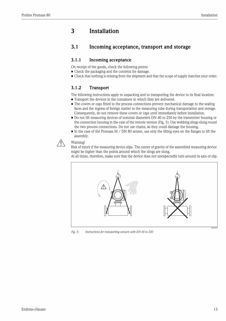
• Do not lift measuring devices of nominal diameters DN 40 to 250 by the transmitter housing or
the connection housing in the case of the remote version (Fig. 5). Use webbing slings slung round
the two process connections. Do not use chains, as they could damage the housing.
• In the case of the Promass M / DN 80 sensor, use only the lifting eyes on the flanges to lift the
assembly.
# Warning!
Risk of injury if the measuring device slips. The center of gravity of the assembled measuring device
might be higher than the points around which the slings are slung.
At all times, therefore, make sure that the device does not unexpectedly turn around its axis or slip.
a0004294
Fig. 5: Instructions for transporting sensors with DN 40 to 250
Installation Proline Promass 80
14 Endress+Hauser
3.1.3 Storage
Note the following points:
• Pack the measuring device in such a way as to protect it reliably against impact for storage (and
transportation). The original packaging provides optimum protection.
• The permissible storage temperature is –40 to +80 °C (preferably +20 °C).
• Do not remove the protective covers or caps on the process connections until you are ready to
install the device.
• The measuring device must be protected against direct sunlight during storage in order to avoid
unacceptably high surface temperatures.
3.2 Installation conditions
Note the following points:
• No special measures such as supports are necessary. External forces are absorbed by the
construction of the instrument, for example the secondary containment.
• The high oscillation frequency of the measuring tubes ensures that the correct operation of the
measuring system is not influenced by pipe vibrations.
• No special precautions need to be taken for fittings which create turbulence (valves, elbows,
T-pieces etc.), as long as no cavitation occurs.
• For mechanical reasons and in order to protect the pipe, it is advisable to support heavy sensors.
3.2.1 Dimensions
All the dimensions and lengths of the sensor and transmitter are provided in the separate
documentation entitled, “Technical Information”.
3.2.2 Mounting location
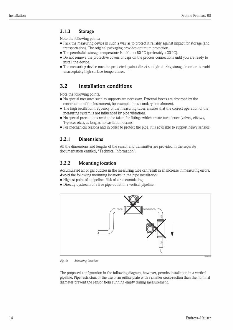
Accumulated air or gas bubbles in the measuring tube can result in an increase in measuring errors.
Avoid the following mounting locations in the pipe installation:
• Highest point of a pipeline. Risk of air accumulating.
• Directly upstream of a free pipe outlet in a vertical pipeline.
a0003605
Fig. 6: Mounting location
The proposed configuration in the following diagram, however, permits installation in a vertical
pipeline. Pipe restrictors or the use of an orifice plate with a smaller cross-section than the nominal
diameter prevent the sensor from running empty during measurement.
Proline Promass 80 Installation
Endress+Hauser 15
a0003597
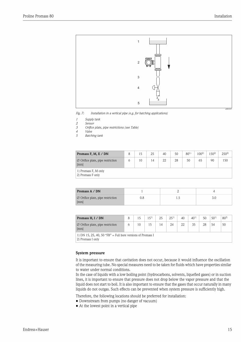
Fig. 7: Installation in a vertical pipe (e.g. for batching applications)
1 Supply tank
2 Sensor
3 Orifice plate, pipe restrictions (see Table)
4 Valve
5 Batching tank
System pressure
It is important to ensure that cavitation does not occur, because it would influence the oscillation
of the measuring tube. No special measures need to be taken for fluids which have properties similar
to water under normal conditions.
In the case of liquids with a low boiling point (hydrocarbons, solvents, liquefied gases) or in suction
lines, it is important to ensure that pressure does not drop below the vapor pressure and that the
liquid does not start to boil. It is also important to ensure that the gases that occur naturally in many
liquids do not outgas. Such effects can be prevented when system pressure is sufficiently high.
Therefore, the following locations should be preferred for installation:
• Downstream from pumps (no danger of vacuum)
• At the lowest point in a vertical pipe
1
2
3
4
5
Promass F, M, E / DN 8 15 25 40 50 801) 1002) 1502) 2502)
∅ Orifice plate, pipe restriction
[mm]
6 10 14 22 28 50 65 90 150
1) Promass F, M only
2) Promass F only
Promass A / DN 1 2 4
∅ Orifice plate, pipe restriction
[mm]
0.8 1.5 3.0
Promass H, I / DN 8 15 151) 25 251) 40 401) 50 501) 802)
∅ Orifice plate, pipe restriction
[mm]
6 10 15 14 24 22 35 28 54 50
1) DN 15, 25, 40, 50 “FB” = Full bore versions of Promass I
2) Promass I only
Installation Proline Promass 80
16 Endress+Hauser
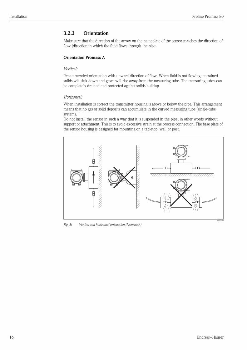
3.2.3 Orientation
Make sure that the direction of the arrow on the nameplate of the sensor matches the direction of
flow (direction in which the fluid flows through the pipe.
Orientation Promass A
Vertical:
Recommended orientation with upward direction of flow. When fluid is not flowing, entrained
solids will sink down and gases will rise away from the measuring tube. The measuring tubes can
be completely drained and protected against solids buildup.
Horizontal:
When installation is correct the transmitter housing is above or below the pipe. This arrangement
means that no gas or solid deposits can accumulate in the curved measuring tube (single-tube
system).
Do not install the sensor in such a way that it is suspended in the pipe, in other words without
support or attachment. This is to avoid excessive strain at the process connection. The base plate of
the sensor housing is designed for mounting on a tabletop, wall or post.
a0003606
Fig. 8: Vertical and horizontal orientation (Promass A)
Proline Promass 80 Installation
Endress+Hauser 17
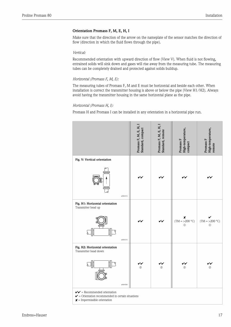
Orientation Promass F, M, E, H, I
Make sure that the direction of the arrow on the nameplate of the sensor matches the direction of
flow (direction in which the fluid flows through the pipe).
Vertical:
Recommended orientation with upward direction of flow (View V). When fluid is not flowing,
entrained solids will sink down and gases will rise away from the measuring tube. The measuring
tubes can be completely drained and protected against solids buildup.
Horizontal (Promass F, M, E):
The measuring tubes of Promass F, M and E must be horizontal and beside each other. When
installation is correct the transmitter housing is above or below the pipe (View H1/H2). Always
avoid having the transmitter housing in the same horizontal plane as the pipe.
Horizontal (Promass H, I):
Promass H and Promass I can be installed in any orientation in a horizontal pipe run.
Pro
mass
F,
M,
E,
H,
I
Sta
nd
ard
, com
pact
Pro
mass
F,
M,
E,
H,
I
Sta
nd
ard
, re
mote
Pro
mass
F
Hig
h-t
em
pera
ture
,
com
pact
Pro
mass
F
Hig
h-t
em
pera
ture
,
rem
ote
Fig. V: Vertical orientation
a0004572
ÃÃ ÃÃ ÃÃ ÃÃ
Fig. H1: Horizontal orientation
Transmitter head up
a0004576
ÃÃ ÃÃ
(TM = >200 °C)
m
Ã(TM = >200 °C)
m
Fig. H2: Horizontal orientation
Transmitter head down
a0004580
ÃÃn
ÃÃn
ÃÃn
ÃÃn
ÃÃ = Recommended orientation
à = Orientation recommended in certain situations
= Impermissible orientation
Installation Proline Promass 80
18 Endress+Hauser
In order to ensure that the maximum permissible ambient temperature for the transmitter (−20 to
+60 °C, optional –40 to +60 °C) is not exceeded, we recommend the following orientations:
m= For fluids with very high temperatures (> 200 °C), we recommend the horizontal orientation
with the transmitter head pointing downwards (Fig. H2) or the vertical orientation (Fig. V).
n = For fluids with low temperatures, we recommend the horizontal orientation with the
transmitter head pointing upwards (Fig. H1) or the vertical orientation (Fig. V).
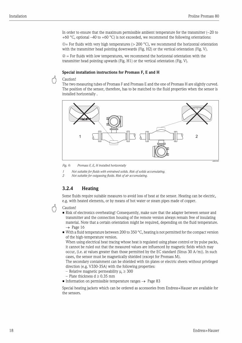
Special installation instructions for Promass F, E and H
" Caution!
The two measuring tubes of Promass F and Promass E and the one of Promass H are slightly curved.
The position of the sensor, therefore, has to be matched to the fluid properties when the sensor is
installed horizontally .
a0004581
Fig. 9: Promass F, E, H installed horizontally
1 Not suitable for fluids with entrained solids. Risk of solids accumulating.
2 Not suitable for outgassing fluids. Risk of air accumulating.
3.2.4 Heating
Some fluids require suitable measures to avoid loss of heat at the sensor. Heating can be electric,
e.g. with heated elements, or by means of hot water or steam pipes made of copper.
" Caution!
• Risk of electronics overheating! Consequently, make sure that the adapter between sensor and
transmitter and the connection housing of the remote version always remain free of insulating
material. Note that a certain orientation might be required, depending on the fluid temperature.
→ Page 16
• With a fluid temperature between 200 to 350 °C, heating is not permitted for the compact version
of the high-temperature version.
When using electrical heat tracing whose heat is regulated using phase control or by pulse packs,
it cannot be ruled out that the measured values are influenced by magnetic fields which may
occur, (i.e. at values greater than those permitted by the EC standard (Sinus 30 A/m)). In such
cases, the sensor must be magnetically shielded (except for Promass M).
The secondary containment can be shielded with tin plates or electric sheets without privileged
direction (e.g. V330-35A) with the following properties:
– Relative magnetic permeability µr ≥ 300
– Plate thickness d ≥ 0.35 mm
• Information on permissible temperature ranges → Page 83
Special heating jackets which can be ordered as accessories from Endress+Hauser are available for
the sensors.
1 2
Proline Promass 80 Installation
Endress+Hauser 19
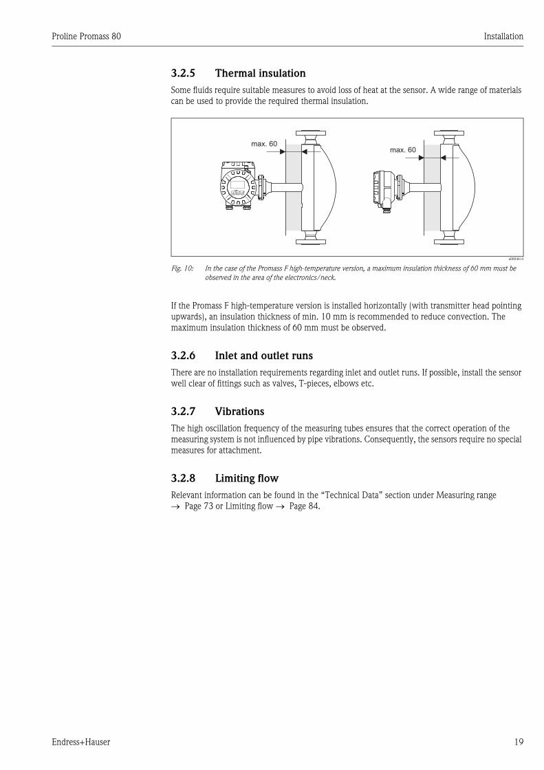
3.2.5 Thermal insulation
Some fluids require suitable measures to avoid loss of heat at the sensor. A wide range of materials
can be used to provide the required thermal insulation.
a0004614
Fig. 10: In the case of the Promass F high-temperature version, a maximum insulation thickness of 60 mm must be
observed in the area of the electronics/neck.
If the Promass F high-temperature version is installed horizontally (with transmitter head pointing
upwards), an insulation thickness of min. 10 mm is recommended to reduce convection. The
maximum insulation thickness of 60 mm must be observed.
3.2.6 Inlet and outlet runs
There are no installation requirements regarding inlet and outlet runs. If possible, install the sensor
well clear of fittings such as valves, T-pieces, elbows etc.
3.2.7 Vibrations
The high oscillation frequency of the measuring tubes ensures that the correct operation of the
measuring system is not influenced by pipe vibrations. Consequently, the sensors require no special
measures for attachment.
3.2.8 Limiting flow
Relevant information can be found in the “Technical Data” section under Measuring range
→ Page 73 or Limiting flow → Page 84.
max. 60
Esc
E- +
max. 60
Installation Proline Promass 80
20 Endress+Hauser
3.3 Installation
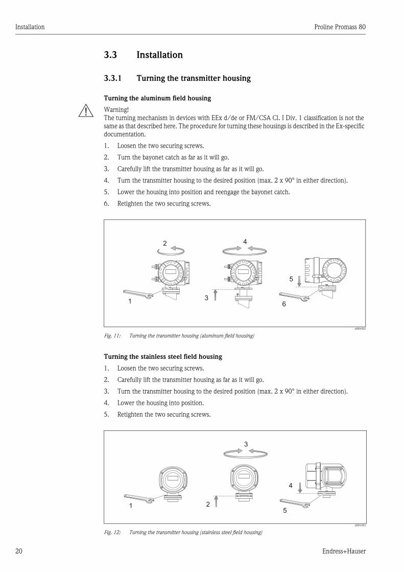
3.3.1 Turning the transmitter housing
Turning the aluminum field housing
# Warning!
The turning mechanism in devices with EEx d/de or FM/CSA Cl. I Div. 1 classification is not the
same as that described here. The procedure for turning these housings is described in the Ex-specific
documentation.
1. Loosen the two securing screws.
2. Turn the bayonet catch as far as it will go.
3. Carefully lift the transmitter housing as far as it will go.
4. Turn the transmitter housing to the desired position (max. 2 x 90° in either direction).
5. Lower the housing into position and reengage the bayonet catch.
6. Retighten the two securing screws.
a0004302
Fig. 11: Turning the transmitter housing (aluminum field housing)
Turning the stainless steel field housing
1. Loosen the two securing screws.
2. Carefully lift the transmitter housing as far as it will go.
3. Turn the transmitter housing to the desired position (max. 2 x 90° in either direction).
4. Lower the housing into position.
5. Retighten the two securing screws.
a0004303
Fig. 12: Turning the transmitter housing (stainless steel field housing)
3
5
61
2 4
1 2
3
4
5
Proline Promass 80 Installation
Endress+Hauser 21
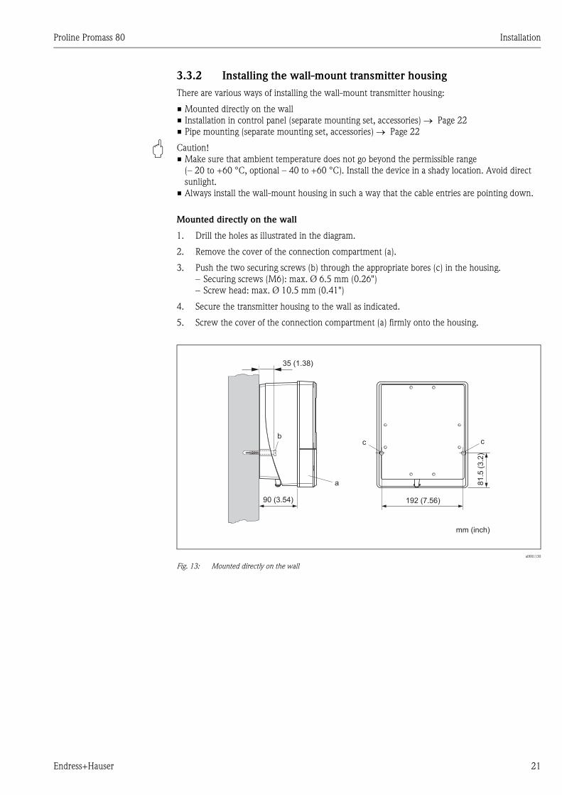
3.3.2 Installing the wall-mount transmitter housing
There are various ways of installing the wall-mount transmitter housing:
• Mounted directly on the wall
• Installation in control panel (separate mounting set, accessories) → Page 22
• Pipe mounting (separate mounting set, accessories) → Page 22
" Caution!
• Make sure that ambient temperature does not go beyond the permissible range
(– 20 to +60 °C, optional – 40 to +60 °C). Install the device in a shady location. Avoid direct
sunlight.
• Always install the wall-mount housing in such a way that the cable entries are pointing down.
Mounted directly on the wall
1. Drill the holes as illustrated in the diagram.
2. Remove the cover of the connection compartment (a).
3. Push the two securing screws (b) through the appropriate bores (c) in the housing.
– Securing screws (M6): max. Ø 6.5 mm (0.26")
– Screw head: max. Ø 10.5 mm (0.41")
4. Secure the transmitter housing to the wall as indicated.
5. Screw the cover of the connection compartment (a) firmly onto the housing.
a0001130
Fig. 13: Mounted directly on the wall
a
bc c
90 (3.54)
35 (1.38)
192 (7.56)
81
.5(3
.2)
mm (inch)
Installation Proline Promass 80
22 Endress+Hauser
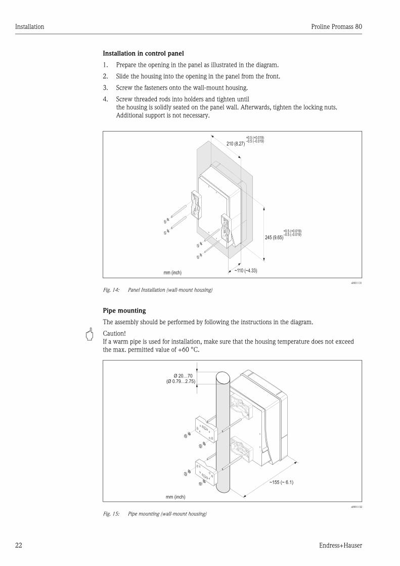
Installation in control panel
1. Prepare the opening in the panel as illustrated in the diagram.
2. Slide the housing into the opening in the panel from the front.
3. Screw the fasteners onto the wall-mount housing.
4. Screw threaded rods into holders and tighten until
the housing is solidly seated on the panel wall. Afterwards, tighten the locking nuts.
Additional support is not necessary.
a0001131
Fig. 14: Panel Installation (wall-mount housing)
Pipe mounting
The assembly should be performed by following the instructions in the diagram.
" Caution!
If a warm pipe is used for installation, make sure that the housing temperature does not exceed
the max. permitted value of +60 °C.
a0001132
Fig. 15: Pipe mounting (wall-mount housing)
245 (9.65)
~110 (~4.33)
210 (8.27)
+0.5 (+0.019)–0.5 (–0.019)
+0.5 (+0.019)–0.5 (–0.019)
mm (inch)
Ø 20…70(Ø 0.79…2.75)
~ ~ 6.1)155 (
mm (inch)
Proline Promass 80 Installation
Endress+Hauser 23
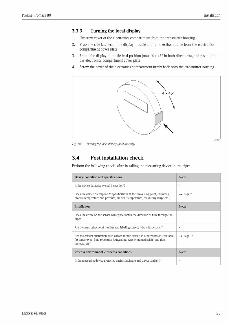
3.3.3 Turning the local display
1. Unscrew cover of the electronics compartment from the transmitter housing.
2. Press the side latches on the display module and remove the module from the electronics
compartment cover plate.
3. Rotate the display to the desired position (max. 4 x 45° in both directions), and reset it onto
the electronics compartment cover plate.
4. Screw the cover of the electronics compartment firmly back onto the transmitter housing.
a0001892
Fig. 16: Turning the local display (field housing)
3.4 Post installation check
Perform the following checks after installing the measuring device in the pipe:
4 x 45°
Device condition and specifications Notes
Is the device damaged (visual inspection)? -
Does the device correspond to specifications at the measuring point, including
process temperature and pressure, ambient temperature, measuring range etc.?
→ Page 7
Installation Notes
Does the arrow on the sensor nameplate match the direction of flow through the
pipe?
-
Are the measuring point number and labeling correct (visual inspection)? -
Has the correct orientation been chosen for the sensor, in other words is it suitable
for sensor type, fluid properties (outgassing, with entrained solids) and fluid
temperature?
→ Page 14
Process environment / process conditions Notes
Is the measuring device protected against moisture and direct sunlight? -
Wiring Proline Promass 80
24 Endress+Hauser
4 Wiring
# Warning!
When connecting Ex-certified devices, see the notes and diagrams in the Ex-specific supplement to
these Operating Instructions. Please do not hesitate to contact your Endress+Hauser sales office if
you have any questions.
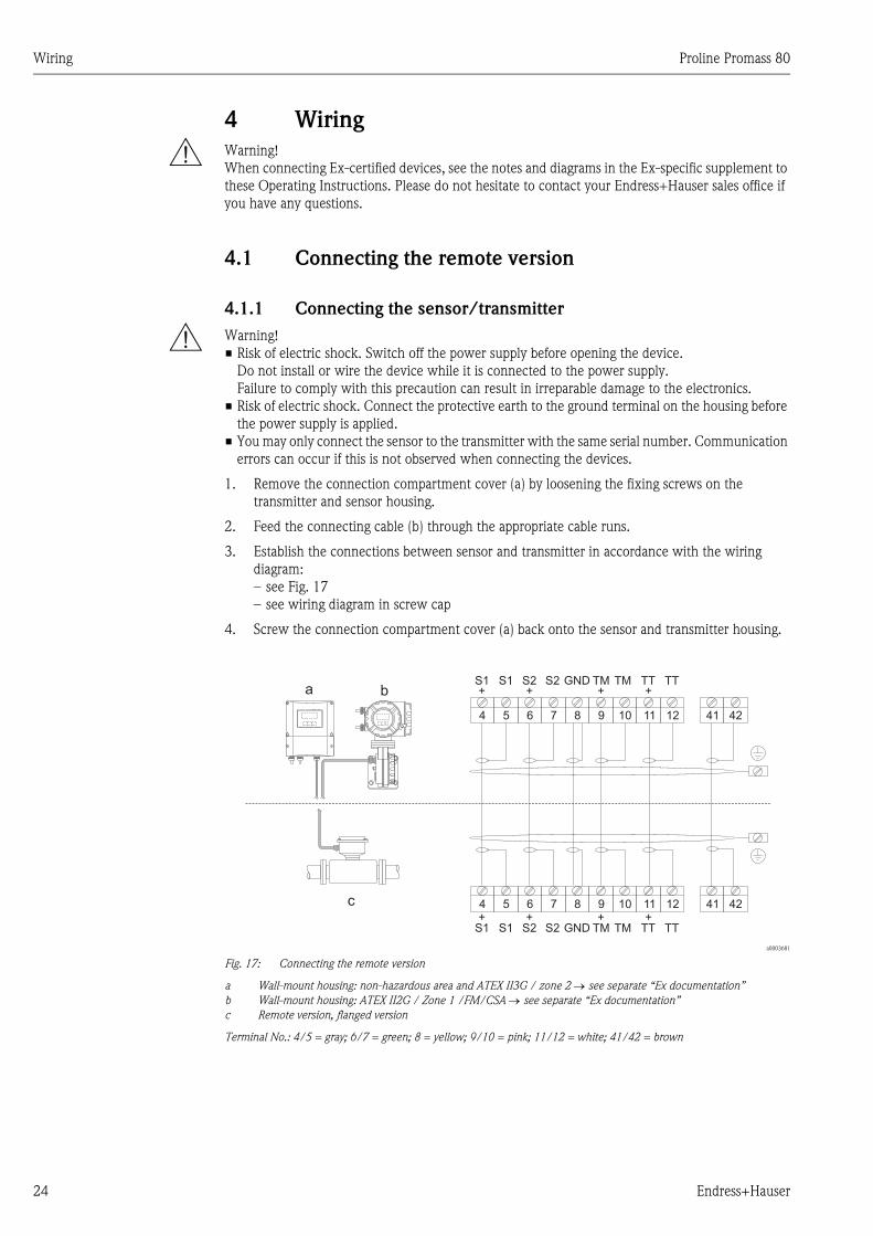
4.1 Connecting the remote version
4.1.1 Connecting the sensor/transmitter
# Warning!
• Risk of electric shock. Switch off the power supply before opening the device.
Do not install or wire the device while it is connected to the power supply.
Failure to comply with this precaution can result in irreparable damage to the electronics.
• Risk of electric shock. Connect the protective earth to the ground terminal on the housing before
the power supply is applied.
• You may only connect the sensor to the transmitter with the same serial number. Communication
errors can occur if this is not observed when connecting the devices.
1. Remove the connection compartment cover (a) by loosening the fixing screws on the
transmitter and sensor housing.
2. Feed the connecting cable (b) through the appropriate cable runs.
3. Establish the connections between sensor and transmitter in accordance with the wiring
diagram:
– see Fig. 17
– see wiring diagram in screw cap
4. Screw the connection compartment cover (a) back onto the sensor and transmitter housing.
a0003681
Fig. 17: Connecting the remote version
a Wall-mount housing: non-hazardous area and ATEX II3G / zone 2 → see separate “Ex documentation”
b Wall-mount housing: ATEX II2G / Zone 1 /FM/CSA → see separate “Ex documentation”
c Remote version, flanged version
Terminal No.: 4/5 = gray; 6/7 = green; 8 = yellow; 9/10 = pink; 11/12 = white; 41/42 = brown
4 5 6 7 8 9 10 11 12 41 42
4 5 6 7 8 9 10 11 12 41 42
S1 S1 S2 S2 GND TM TM TT TT+ + + +
+ + + +S1 S1 S2 S2 GND TM TM TT TT
a b
c
Proline Promass 80 Wiring
Endress+Hauser 25
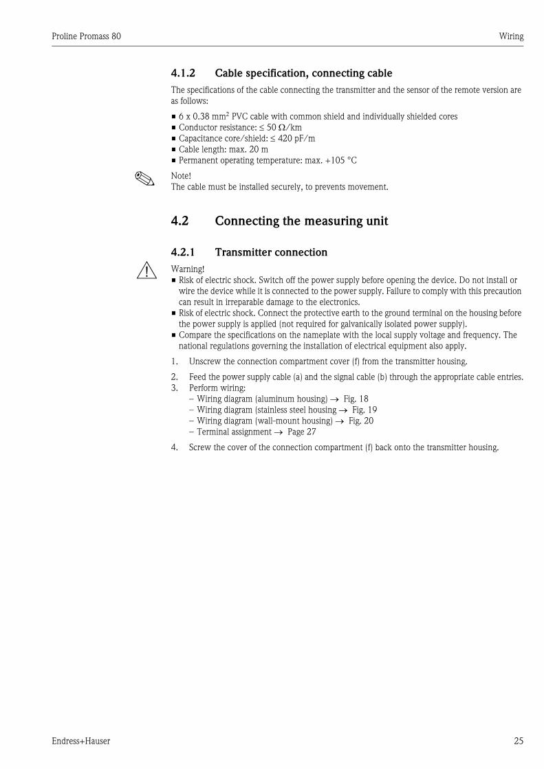
4.1.2 Cable specification, connecting cable
The specifications of the cable connecting the transmitter and the sensor of the remote version are
as follows:
• 6 x 0.38 mm2 PVC cable with common shield and individually shielded cores
• Conductor resistance: ≤ 50 Ω/km
• Capacitance core/shield: ≤ 420 pF/m
• Cable length: max. 20 m
• Permanent operating temperature: max. +105 °C
! Note!
The cable must be installed securely, to prevents movement.
4.2 Connecting the measuring unit
4.2.1 Transmitter connection
# Warning!
• Risk of electric shock. Switch off the power supply before opening the device. Do not install or
wire the device while it is connected to the power supply. Failure to comply with this precaution
can result in irreparable damage to the electronics.
• Risk of electric shock. Connect the protective earth to the ground terminal on the housing before
the power supply is applied (not required for galvanically isolated power supply).
• Compare the specifications on the nameplate with the local supply voltage and frequency. The
national regulations governing the installation of electrical equipment also apply.
1. Unscrew the connection compartment cover (f) from the transmitter housing.
2. Feed the power supply cable (a) and the signal cable (b) through the appropriate cable entries.
3. Perform wiring:
– Wiring diagram (aluminum housing) → Fig. 18
– Wiring diagram (stainless steel housing → Fig. 19
– Wiring diagram (wall-mount housing) → Fig. 20
– Terminal assignment → Page 27
4. Screw the cover of the connection compartment (f) back onto the transmitter housing.
Wiring Proline Promass 80
26 Endress+Hauser
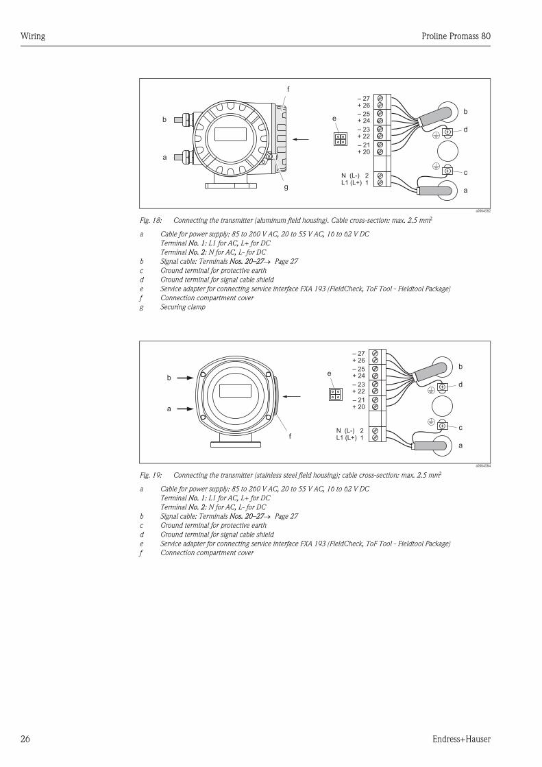
a0004582
Fig. 18: Connecting the transmitter (aluminum field housing). Cable cross-section: max. 2.5 mm2
a Cable for power supply: 85 to 260 V AC, 20 to 55 V AC, 16 to 62 V DC
Terminal No. 1: L1 for AC, L+ for DC
Terminal No. 2: N for AC, L- for DC
b Signal cable: Terminals Nos. 20–27→ Page 27
c Ground terminal for protective earth
d Ground terminal for signal cable shield
e Service adapter for connecting service interface FXA 193 (FieldCheck, ToF Tool - Fieldtool Package)
f Connection compartment cover
g Securing clamp
a0004584
Fig. 19: Connecting the transmitter (stainless steel field housing); cable cross-section: max. 2.5 mm2
a Cable for power supply: 85 to 260 V AC, 20 to 55 V AC, 16 to 62 V DC
Terminal No. 1: L1 for AC, L+ for DC
Terminal No. 2: N for AC, L- for DC
b Signal cable: Terminals Nos. 20–27→ Page 27
c Ground terminal for protective earth
d Ground terminal for signal cable shield
e Service adapter for connecting service interface FXA 193 (FieldCheck, ToF Tool - Fieldtool Package)
f Connection compartment cover
bb
c
d
a
a
21
– 27
– 25
– 23
– 21
+ 26
+ 24
+ 22
+ 20
L1 (L+)N (L-)
g
f
e
b
c
d
a
21L1 (L+)
N (L-)f
b
a
e
– 27
– 25
– 23
– 21
+ 26
+ 24
+ 22
+ 20
Proline Promass 80 Wiring
Endress+Hauser 27
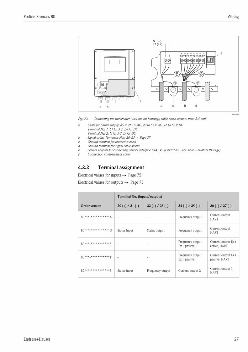
a0001135
Fig. 20: Connecting the transmitter (wall-mount housing); cable cross-section: max. 2.5 mm2
a Cable for power supply: 85 to 260 V AC, 20 to 55 V AC, 16 to 62 V DC
Terminal No. 1: L1 for AC, L+ for DC
Terminal No. 2: N for AC, L- for DC
b Signal cable: Terminals Nos. 20–27→ Page 27
c Ground terminal for protective earth
d Ground terminal for signal cable shield
e Service adapter for connecting service interface FXA 193 (FieldCheck, ToF Tool - Fieldtool Package)
f Connection compartment cover
4.2.2 Terminal assignment
Electrical values for inputs → Page 75
Electrical values for outputs → Page 75
1 2
c d
e
aa bb
f
+22
–23
+20
–21
+24
–25
+26
–27
L1 (L+)N (L-)
Terminal No. (inputs/outputs)
Order version 20 (+) / 21 (–) 22 (+) / 23 (–) 24 (+) / 25 (–) 26 (+) / 27 (–)
80***-***********A - - Frequency outputCurrent output
HART
80***-***********D Status input Status output Frequency outputCurrent output
HART
80***-***********S - -Frequency output
Ex i, passive
Current output Ex i
active, HART
80***-***********T - -Frequency output
Ex i, passive
Current output Ex i
passive, HART
80***-***********8 Status input Frequency output Current output 2Current output 1
HART
Wiring Proline Promass 80
28 Endress+Hauser
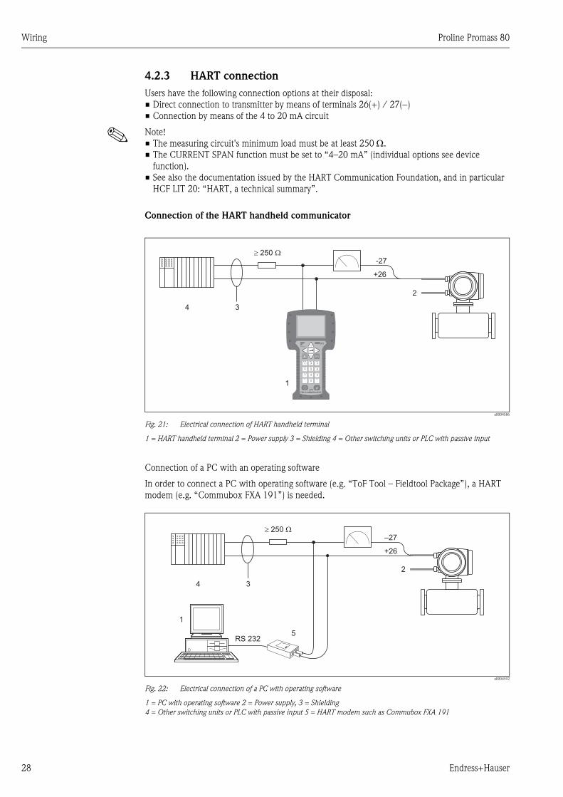
4.2.3 HART connection
Users have the following connection options at their disposal:
• Direct connection to transmitter by means of terminals 26(+) / 27(−)
• Connection by means of the 4 to 20 mA circuit
! Note!
• The measuring circuit's minimum load must be at least 250 Ω.
• The CURRENT SPAN function must be set to “4–20 mA” (individual options see device
function).
• See also the documentation issued by the HART Communication Foundation, and in particular
HCF LIT 20: “HART, a technical summary”.
Connection of the HART handheld communicator
a0004586
Fig. 21: Electrical connection of HART handheld terminal
1 = HART handheld terminal 2 = Power supply 3 = Shielding 4 = Other switching units or PLC with passive input
Connection of a PC with an operating software
In order to connect a PC with operating software (e.g. “ToF Tool – Fieldtool Package”), a HART
modem (e.g. “Commubox FXA 191”) is needed.
a0004592
Fig. 22: Electrical connection of a PC with operating software
1 = PC with operating software 2 = Power supply, 3 = Shielding
4 = Other switching units or PLC with passive input 5 = HART modem such as Commubox FXA 191
+26
³ W250-27
1
34
2
1# % &
Copy
G H I
P Q R S
, ( ) ‘
A B C
Paste
PageOn
PageUp
DeleteBksp
Insert
J K L
T U V
_ < >
D E F
Hot Key
+ Hot Key
M N O
W X Y Z
+ * /
4
7
.
2
5
8
0
375FIELD COMMUNICATOR
3
6
9
-
+26
³ W250–27
RS 232
1
2
3
5
4
Proline Promass 80 Wiring
Endress+Hauser 29
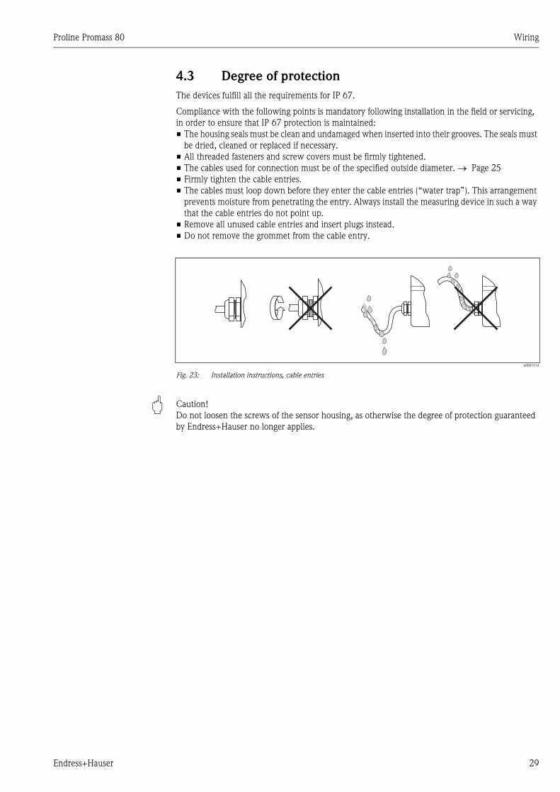
4.3 Degree of protection
The devices fulfill all the requirements for IP 67.
Compliance with the following points is mandatory following installation in the field or servicing,
in order to ensure that IP 67 protection is maintained:
• The housing seals must be clean and undamaged when inserted into their grooves. The seals must
be dried, cleaned or replaced if necessary.
• All threaded fasteners and screw covers must be firmly tightened.
• The cables used for connection must be of the specified outside diameter. → Page 25
• Firmly tighten the cable entries.
• The cables must loop down before they enter the cable entries (“water trap”). This arrangement
prevents moisture from penetrating the entry. Always install the measuring device in such a way
that the cable entries do not point up.
• Remove all unused cable entries and insert plugs instead.
• Do not remove the grommet from the cable entry.
a0001914
Fig. 23: Installation instructions, cable entries
" Caution!
Do not loosen the screws of the sensor housing, as otherwise the degree of protection guaranteed
by Endress+Hauser no longer applies.
Wiring Proline Promass 80
30 Endress+Hauser
4.4 Post connection check
Perform the following checks after completing electrical installation of the measuring device:
Device condition and specifications Notes
Are cables or the device damaged (visual inspection)? -
Electrical connection Notes
Does the supply voltage match the specifications on the nameplate? 85 to 260 V AC (45 to 65 Hz)
20 to 55 V AC (45 to 65 Hz)
16 to 62 V DC
Do the cables comply with the specifications? → Page 25
Do the cables have adequate strain relief? -
Cables correctly segregated by type?
Without loops and crossovers?
-
Are the power supply and signal cables correctly connected? See the wiring diagram inside
the cover of the terminal
compartment
Are all screw terminals firmly tightened? -
Are all cable entries installed, firmly tightened and correctly sealed?
Cables looped as “water traps”?
→ Page 29
Are all housing covers installed and firmly tightened? -
Proline Promass 80 Operation
Endress+Hauser 31
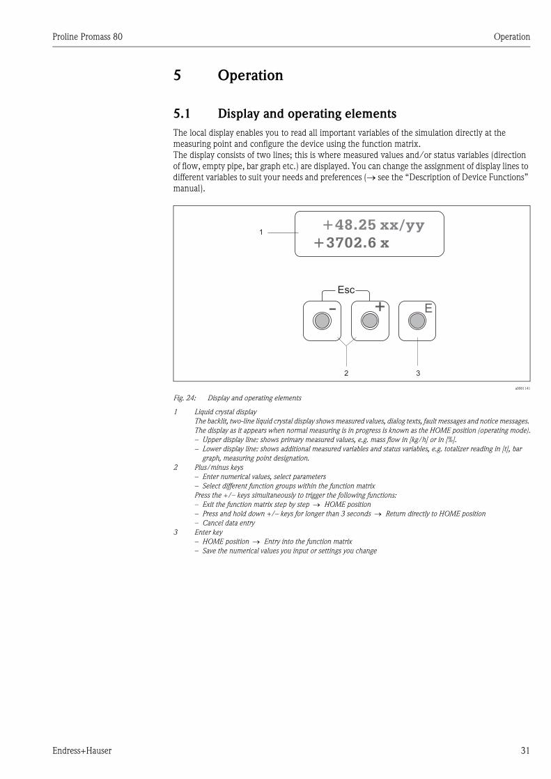
5 Operation
5.1 Display and operating elements
The local display enables you to read all important variables of the simulation directly at the
measuring point and configure the device using the function matrix.
The display consists of two lines; this is where measured values and/or status variables (direction
of flow, empty pipe, bar graph etc.) are displayed. You can change the assignment of display lines to
different variables to suit your needs and preferences (→ see the “Description of Device Functions”
manual).
a0001141
Fig. 24: Display and operating elements
1 Liquid crystal display
The backlit, two-line liquid crystal display shows measured values, dialog texts, fault messages and notice messages.
The display as it appears when normal measuring is in progress is known as the HOME position (operating mode).
– Upper display line: shows primary measured values, e.g. mass flow in [kg/h] or in [%].
– Lower display line: shows additional measured variables and status variables, e.g. totalizer reading in [t], bar
graph, measuring point designation.
2 Plus/minus keys
– Enter numerical values, select parameters
– Select different function groups within the function matrix
Press the +/– keys simultaneously to trigger the following functions:
– Exit the function matrix step by step → HOME position
– Press and hold down +/– keys for longer than 3 seconds → Return directly to HOME position
– Cancel data entry
3 Enter key
– HOME position → Entry into the function matrix
– Save the numerical values you input or settings you change
Esc
E+-
1
32
+48.25 xx/yy
+3702.6 x
Operation Proline Promass 80
32 Endress+Hauser
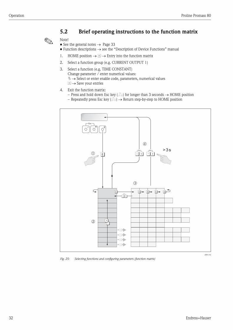
5.2 Brief operating instructions to the function matrix
! Note!
• See the general notes → Page 33
• Function descriptions → see the “Description of Device Functions” manual
1. HOME position → F → Entry into the function matrix
2. Select a function group (e.g. CURRENT OUTPUT 1)
3. Select a function (e.g. TIME CONSTANT)
Change parameter / enter numerical values:
P → Select or enter enable code, parameters, numerical values
F → Save your entries
4. Exit the function matrix:
– Press and hold down Esc key (X) for longer than 3 seconds → HOME position
– Repeatedly press Esc key (X) → Return step-by-step to HOME position
a0001142
Fig. 25: Selecting functions and configuring parameters (function matrix)
>3s
- + E
Esc
E
E
E
E
E E E E E
–
+
+
Esc
–+
Esc
–
+
Esc
–
Em
n
o
p
Proline Promass 80 Operation
Endress+Hauser 33
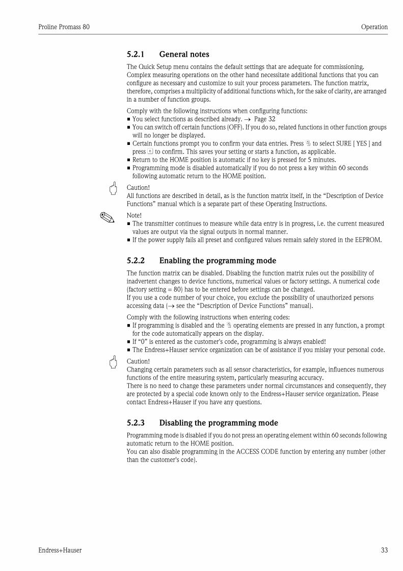
5.2.1 General notes
The Quick Setup menu contains the default settings that are adequate for commissioning.
Complex measuring operations on the other hand necessitate additional functions that you can
configure as necessary and customize to suit your process parameters. The function matrix,
therefore, comprises a multiplicity of additional functions which, for the sake of clarity, are arranged
in a number of function groups.
Comply with the following instructions when configuring functions:
• You select functions as described already. → Page 32
• You can switch off certain functions (OFF). If you do so, related functions in other function groups
will no longer be displayed.
• Certain functions prompt you to confirm your data entries. Press P to select SURE [ YES ] and
press F to confirm. This saves your setting or starts a function, as applicable.
• Return to the HOME position is automatic if no key is pressed for 5 minutes.
• Programming mode is disabled automatically if you do not press a key within 60 seconds
following automatic return to the HOME position.
" Caution!
All functions are described in detail, as is the function matrix itself, in the “Description of Device
Functions” manual which is a separate part of these Operating Instructions.
! Note!
• The transmitter continues to measure while data entry is in progress, i.e. the current measured
values are output via the signal outputs in normal manner.
• If the power supply fails all preset and configured values remain safely stored in the EEPROM.
5.2.2 Enabling the programming mode
The function matrix can be disabled. Disabling the function matrix rules out the possibility of
inadvertent changes to device functions, numerical values or factory settings. A numerical code
(factory setting = 80) has to be entered before settings can be changed.
If you use a code number of your choice, you exclude the possibility of unauthorized persons
accessing data (→ see the “Description of Device Functions” manual).
Comply with the following instructions when entering codes:
• If programming is disabled and the P operating elements are pressed in any function, a prompt
for the code automatically appears on the display.
• If “0” is entered as the customer's code, programming is always enabled!
• The Endress+Hauser service organization can be of assistance if you mislay your personal code.
" Caution!
Changing certain parameters such as all sensor characteristics, for example, influences numerous
functions of the entire measuring system, particularly measuring accuracy.
There is no need to change these parameters under normal circumstances and consequently, they
are protected by a special code known only to the Endress+Hauser service organization. Please
contact Endress+Hauser if you have any questions.
5.2.3 Disabling the programming mode
Programming mode is disabled if you do not press an operating element within 60 seconds following
automatic return to the HOME position.
You can also disable programming in the ACCESS CODE function by entering any number (other
than the customer's code).
Operation Proline Promass 80
34 Endress+Hauser
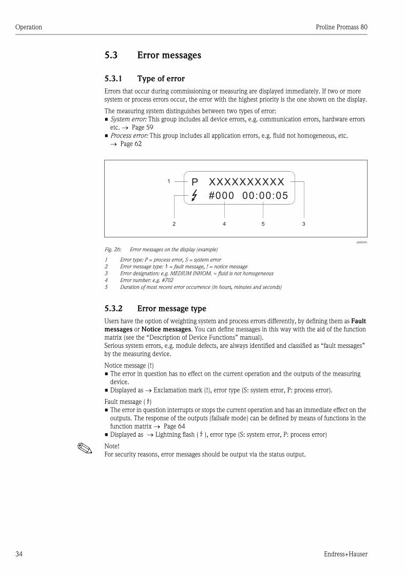
5.3 Error messages
5.3.1 Type of error
Errors that occur during commissioning or measuring are displayed immediately. If two or more
system or process errors occur, the error with the highest priority is the one shown on the display.
The measuring system distinguishes between two types of error:
• System error: This group includes all device errors, e.g. communication errors, hardware errors
etc. → Page 59
• Process error: This group includes all application errors, e.g. fluid not homogeneous, etc.
→ Page 62
a0000991
Fig. 26: Error messages on the display (example)
1 Error type: P = process error, S = system error
2 Error message type: $ = fault message, ! = notice message
3 Error designation: e.g. MEDIUM INHOM. = fluid is not homogeneous
4 Error number: e.g. #702
5 Duration of most recent error occurrence (in hours, minutes and seconds)
5.3.2 Error message type
Users have the option of weighting system and process errors differently, by defining them as Fault
messages or Notice messages. You can define messages in this way with the aid of the function
matrix (see the “Description of Device Functions” manual).
Serious system errors, e.g. module defects, are always identified and classified as “fault messages”
by the measuring device.
Notice message (!)
• The error in question has no effect on the current operation and the outputs of the measuring
device.
• Displayed as → Exclamation mark (!), error type (S: system error, P: process error).
Fault message ( $)• The error in question interrupts or stops the current operation and has an immediate effect on the
outputs. The response of the outputs (failsafe mode) can be defined by means of functions in the
function matrix → Page 64
• Displayed as → Lightning flash ( $ ), error type (S: system error, P: process error)
! Note!
For security reasons, error messages should be output via the status output.
1
2 4 5 3
XXXXXXXXXX
#000 00:00:05
P
Proline Promass 80 Operation
Endress+Hauser 35
5.4 Communication
In addition to local operation, the measuring device can be configured and measured values can be
obtained by means of the HART protocol. Digital communication takes place using the 4–20 mA
current output HART. → Page 28
The HART protocol allows the transfer of measuring and device data between the HART master and
the field devices for configuration and diagnostics purposes. The HART master, e.g. a handheld
terminal or PC-based operating programs (such as ToF Tool – Fieldtool Package), require device
description (DD) files which are used to access all the information in a HART device. Information is
exclusively transferred using “commands”. There are three different command groups:
There are three different command groups:
• Universal Commands
Universal commands are supported and used by all HART devices. The following are examples of
functions connected with them:
– Recognizing HART devices
– Reading digital measured values (volume flow, totalizer etc.)
• Common practice commands:
Common practice commands offer functions which are supported and can be executed by most
but not all field devices.
• Device-specific commands:
These commands allow access to device-specific functions which are not HART standard. Such
commands access individual field device information, among other things, such as empty/full
pipe calibration values, low flow cut off settings, etc.
! Note!
The measuring device has access to all three command classes.
List of all “Universal Commands” and “Common Practice Commands”: → Page 39

Operation Proline Promass 80
36 Endress+Hauser
5.4.1 Operating options
For the complete operation of the measuring device, including device-specific commands, there are
DD files available to the user to provide the following operating aids and programs:
! Note!
• The HART protocol requires the “4…20 mA HART” setting (individual options see device
function) in the CURRENT SPAN function (current output 1).
HART
handheld terminal DXR 375
Selecting device functions with a HART Communicator is a process involving a number of menu
levels and a special HART function matrix.
The HART manual in the carrying case of the HART Communicator contains more detailed
information on the device.
Operating program “ToF Tool – Fieldtool Package”
Modular software package consisting of the service program “ToF Tool” for configuration and
diagnosis of ToF level measuring devices (time-of-flight measurement) and evolution of pressure
measuring instruments as well as the “Fieldtool” service program for the configuration and diagnosis
of Proline flow measuring devices. The Proline flow measuring devices are accessed via a service
interface or via the service interface FXA 193 or the HART protocol.
Contents of the “ToF Tool – Fieldtool Package”:
• Commissioning, maintenance analysis
• Configuring flowmeters
• Service functions
• Visualization of process data
• Troubleshooting
• Controlling the “Fieldcheck” tester/simulator
FieldCare
FieldCare is Endress+Hauser’s FDT-based plant Asset Management Tool and allows the
configuration and diagnosis of intelligent field devices. By using status information, you also have a
simple but effective tool for monitoring devices. The Proline flow measuring devices are accessed
via a service interface or via the service interface FXA 193.
Operating program “SIMATIC PDM” (Siemens)
SIMATIC PDM is a standardized, manufacturer-independent tool for the operation, configuration,
maintenance and diagnosis of intelligent field devices.
Operating program “AMS” (Emerson Process Management)
AMS (Asset Management Solutions): program for operating and configuring devices
Proline Promass 80 Operation
Endress+Hauser 37
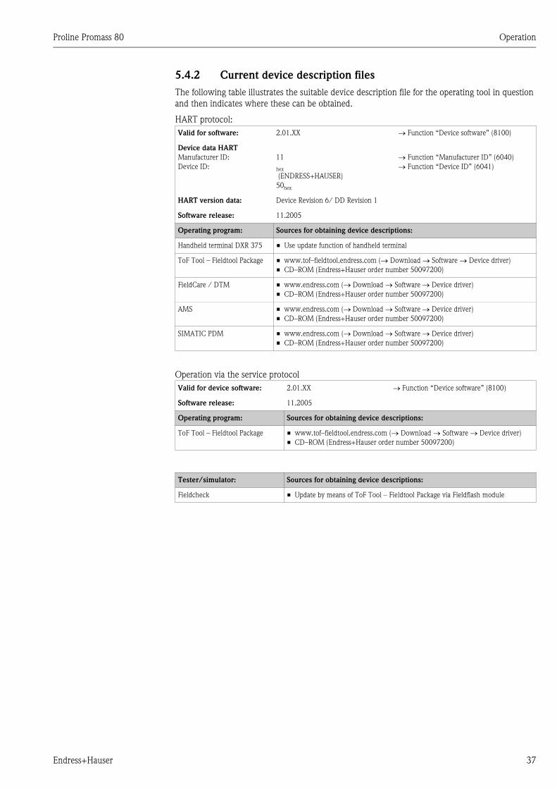
5.4.2 Current device description files
The following table illustrates the suitable device description file for the operating tool in question
and then indicates where these can be obtained.
HART protocol:
Operation via the service protocol
Valid for software: 2.01.XX → Function “Device software” (8100)
Device data HART
Manufacturer ID:
Device ID:
11
hex
(ENDRESS+HAUSER)
50hex
→ Function “Manufacturer ID” (6040)
→ Function “Device ID” (6041)
HART version data: Device Revision 6/ DD Revision 1
Software release: 11.2005
Operating program: Sources for obtaining device descriptions:
Handheld terminal DXR 375 • Use update function of handheld terminal
ToF Tool – Fieldtool Package • www.tof–fieldtool.endress.com (→ Download → Software → Device driver)
• CD–ROM (Endress+Hauser order number 50097200)
FieldCare / DTM • www.endress.com (→ Download → Software → Device driver)
• CD–ROM (Endress+Hauser order number 50097200)
AMS • www.endress.com (→ Download → Software → Device driver)
• CD–ROM (Endress+Hauser order number 50097200)
SIMATIC PDM • www.endress.com (→ Download → Software → Device driver)
• CD–ROM (Endress+Hauser order number 50097200)
Valid for device software: 2.01.XX → Function “Device software” (8100)
Software release: 11.2005
Operating program: Sources for obtaining device descriptions:
ToF Tool – Fieldtool Package • www.tof–fieldtool.endress.com (→ Download → Software → Device driver)
• CD–ROM (Endress+Hauser order number 50097200)
Tester/simulator: Sources for obtaining device descriptions:
Fieldcheck • Update by means of ToF Tool – Fieldtool Package via Fieldflash module
Operation Proline Promass 80
38 Endress+Hauser
5.4.3 Device and process variables
Device variables:
The following device variables are available using the HART protocol:
Process variables:
At the factory, the process variables are assigned to the following device variables:
• Primary process variable (PV) → Mass flow
• Secondary process variable (SV) → Totalizer 1
• Third process variable (TV) → Density
• Fourth process variable (FV) → Temperature
! Note!
You can set or change the assignment of device variables to process variables using Command 51.
→ Page 42
Code (decimal) Device variable
0 OFF (unassigned)
2 Mass flow
5 Volume flow
6 Corrected volume flow
7 Density
8 Reference density
9 Temperature
250 Totalizer 1
251 Totalizer 2
Proline Promass 80 Operation
Endress+Hauser 39
5.4.4 Universal / Common practice HART commands
The following table contains all the universal and common practice commands supported by the
device.
Command No.
HART command / Access type
Command data
(numeric data in decimal form)
Response data
(numeric data in decimal form)
Universal Commands
0 Read unique device identifier
Access type = read
none Device identification delivers information on the device
and the manufacturer. It cannot be changed.
The response consists of a 12-byte device ID:
– Byte 0: fixed value 254
– Byte 1: Manufacturer ID, 17 = E+H
– Byte 2: Device type ID, e.g. 81 = Promass 83
or 80 = Promass 80
– Byte 3: Number of preambles
– Byte 4: Universal commands rev. no.
– Byte 5: Device-specific commands rev. no.
– Byte 6: Software revision
– Byte 7: Hardware revision
– Byte 8: Additional device information
– Bytes 9-11: Device identification
1 Read primary process variable
Access type = read
none – Byte 0: HART unit code of the primary process
variable
– Bytes 1-4: Primary process variable
Factory setting:
Primary process variable = Mass flow
! Note!
• You can set the assignment of device variables to
process variables using Command 51.
• Manufacturer-specific units are represented using the
HART unit code “240”.
2 Read the primary process variable as
current in mA and percentage of the
set measuring range
Access type = read
none – Bytes 0-3: Current current of the primary process
variable in mA
– Bytes 4-7: Percentage of the set measuring range
Factory setting:
Primary process variable = Mass flow
! Note!
You can set the assignment of device variables to process
variables using Command 51.
3 Read the primary process variable as
current in mA and four (preset
using Command 51) dynamic
process variables
Access type = read
none 24 bytes are sent as a response:
– Bytes 0-3: Primary process variable current in mA
– Byte 4: HART unit code of the primary process
variable
– Bytes 5-8: Primary process variable
– Byte 9: HART unit code of the secondary process
variable
– Bytes 10-13: Secondary process variable
– Byte 14: HART unit code of the third process variable
– Bytes 15-18: Third process variable
– Byte 19: HART unit code of the fourth process
variable
– Bytes 20-23: Fourth process variable
Factory setting:
• Primary process variable = Mass flow
• Secondary process variable = Totalizer 1
• Third process variable = Density
• Fourth process variable = Temperature
! Note!
• You can set the assignment of device variables to
process variables using Command 51.
• Manufacturer-specific units are represented using the
HART unit code “240”.
Operation Proline Promass 80
40 Endress+Hauser
6 Set HART shortform address
Access type = write
Byte 0: desired address (0 to 15)
Factory setting:
0
! Note!
With an address >0 (multidrop mode), the current
output of the primary process variable is set to 4 mA.
Byte 0: active address
11 Read unique device identification
using the TAG (measuring point
designation)
Access type = read
Bytes 0-5: TAG Device identification delivers information on the device
and the manufacturer. It cannot be changed.
The response consists of a 12-byte device ID if the
specified TAG agrees with the one saved in the device:
– Byte 0: fixed value 254
– Byte 1: Manufacturer ID, 17 = E+H
– Byte 2: Device type ID, 81 = Promass 83
or 80 = Promass 80
– Byte 3: Number of preambles
– Byte 4: Universal commands rev. no.
– Byte 5: Device-specific commands rev. no.
– Byte 6: Software revision
– Byte 7: Hardware revision
– Byte 8: Additional device information
– Bytes 9-11: Device identification
12 Read user message
Access type = read
none Bytes 0-24: User message
! Note!
You can write the user message using Command 17.
13 Read TAG, descriptor and date
Access type = read
none – Bytes 0-5: TAG
– Bytes 6-17: Descriptor
– Bytes 18-20: Date
! Note!
You can write the TAG, descriptor and date using
Command 18.
14 Read sensor information on primary
process variable
none – Bytes 0-2: Sensor serial number
– Byte 3: HART unit code of sensor limits and
measuring range of the primary process variable
– Bytes 4-7: Upper sensor limit
– Bytes 8-11: Lower sensor limit
– Bytes 12-15: Minimum span
! Note!
• The data relate to the primary process variable
(= Mass flow).
• Manufacturer-specific units are represented using the
HART unit code “240”.
15 Read output information of primary
process variable
Access type = read
none – Byte 0: Alarm selection ID
– Byte 1: Transfer function ID
– Byte 2: HART unit code for the set measuring range of
the primary process variable
– Bytes 3-6: Upper range, value for 20 mA
– Bytes 7-10: Start of measuring range, value for 4 mA
– Bytes 11-14: Attenuation constant in [s]
– Byte 15: Write protection ID
– Byte 16: OEM dealer ID, 17 = E+H
Factory setting:
Primary process variable = Mass flow
! Note!
• You can set the assignment of device variables to
process variables using Command 51.
• Manufacturer-specific units are represented using the
HART unit code “240”.
Command No.
HART command / Access type
Command data
(numeric data in decimal form)
Response data
(numeric data in decimal form)
Proline Promass 80 Operation
Endress+Hauser 41
The following table contains all the common practice commands supported by the device.
16 Read the device production number
Access type = read
none Bytes 0-2: Production number
17 Write user message
Access = write
You can save any 32-character long text in the device
under this parameter:
Bytes 0-23: Desired user message
Displays the current user message in the device:
Bytes 0-23: Current user message in the device
18 Write TAG, descriptor and date
Access = write
With this parameter, you can store an 8 character TAG, a
16 character descriptor and a date:
– Bytes 0-5: TAG
– Bytes 6-17: Descriptor
– Bytes 18-20: Date
Displays the current information in the device:
– Bytes 0-5: TAG
– Bytes 6-17: Descriptor
– Bytes 18-20: Date
Command No.
HART command / Access type
Command data
(numeric data in decimal form)
Response data
(numeric data in decimal form)
Command No.
HART command / Access type
Command data
(numeric data in decimal form)
Response data
(numeric data in decimal form)
Common Practice Commands
34 Write damping value for primary
process variable
Access = write
Bytes 0-3: Attenuation constant of the primary process
variable in seconds
Factory setting:
Primary process variable = Mass flow
Displays the current damping value in the device:
Bytes 0-3: Damping value in seconds
35 Write measuring range of primary
process variable
Access = write
Write the desired measuring range:
– Byte 0: HART unit code of the primary process
variable
– Bytes 1-4: Upper range, value for 20 mA
– Bytes 5-8: Start of measuring range, value for 4 mA
Factory setting:
Primary process variable = Mass flow
! Note!
• You can set the assignment of device variables to
process variables using Command 51.
• If the HART unit code is not the correct one for the
process variable, the device will continue with the last
valid unit.
The currently set measuring range is displayed as a
response:
– Byte 0: HART unit code for the set measuring range of
the primary process variable
– Bytes 1-4: Upper range, value for 20 mA
– Bytes 5-8: Start of measuring range, value for 4 mA
! Note!
Manufacturer-specific units are represented using the
HART unit code “240”.
38 Device status reset (Configuration
changed)
Access = write
none none
40 Simulate output current of primary
process variable
Access = write
Simulation of the desired output current of the primary
process variable.
An entry value of 0 exits the simulation mode:
Byte 0-3: Output current in mA
Factory setting:
Primary process variable = Mass flow
! Note!
You can set the assignment of device variables to process
variables with Command 51.
The momentary output current of the primary process
variable is displayed as a response:
Byte 0-3: Output current in mA
42 Perform master reset
Access = write
none none
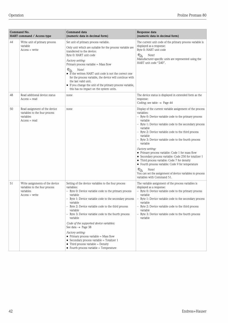
Operation Proline Promass 80
42 Endress+Hauser
44 Write unit of primary process
variable
Access = write
Set unit of primary process variable.
Only unit which are suitable for the process variable are
transferred to the device:
Byte 0: HART unit code
Factory setting:
Primary process variable = Mass flow
! Note!
• If the written HART unit code is not the correct one
for the process variable, the device will continue with
the last valid unit.
• If you change the unit of the primary process variable,
this has no impact on the system units.
The current unit code of the primary process variable is
displayed as a response:
Byte 0: HART unit code
! Note!
Manufacturer-specific units are represented using the
HART unit code “240”.
48 Read additional device status
Access = read
none The device status is displayed in extended form as the
response:
Coding: see table → Page 44
50 Read assignment of the device
variables to the four process
variables
Access = read
none Display of the current variable assignment of the process
variables:
– Byte 0: Device variable code to the primary process
variable
– Byte 1: Device variable code to the secondary process
variable
– Byte 2: Device variable code to the third process
variable
– Byte 3: Device variable code to the fourth process
variable
Factory setting:
• Primary process variable: Code 1 for mass flow
• Secondary process variable: Code 250 for totalizer 1
• Third process variable: Code 7 for density
• Fourth process variable: Code 9 for temperature
! Note!
You can set the assignment of device variables to process
variables with Command 51.
51 Write assignments of the device
variables to the four process
variables
Access = write
Setting of the device variables to the four process
variables:
– Byte 0: Device variable code to the primary process
variable
– Byte 1: Device variable code to the secondary process
variable
– Byte 2: Device variable code to the third process
variable
– Byte 3: Device variable code to the fourth process
variable
Code of the supported device variables:
See data → Page 38
Factory setting:
• Primary process variable = Mass flow
• Secondary process variable = Totalizer 1
• Third process variable = Density
• Fourth process variable = Temperature
The variable assignment of the process variables is
displayed as a response:
– Byte 0: Device variable code to the primary process
variable
– Byte 1: Device variable code to the secondary process
variable
– Byte 2: Device variable code to the third process
variable
– Byte 3: Device variable code to the fourth process
variable
Command No.
HART command / Access type
Command data
(numeric data in decimal form)
Response data
(numeric data in decimal form)
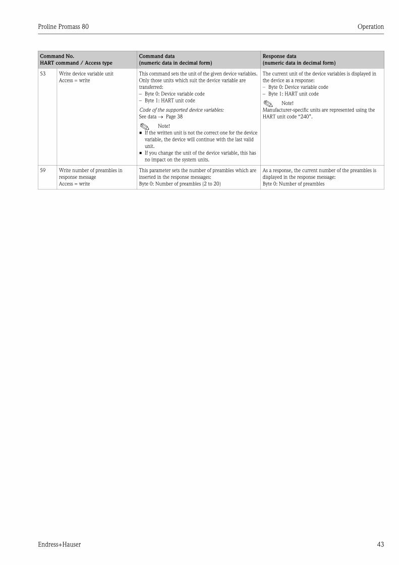
Proline Promass 80 Operation
Endress+Hauser 43
53 Write device variable unit
Access = write
This command sets the unit of the given device variables.
Only those units which suit the device variable are
transferred:
– Byte 0: Device variable code
– Byte 1: HART unit code
Code of the supported device variables:
See data → Page 38
! Note!
• If the written unit is not the correct one for the device
variable, the device will continue with the last valid
unit.
• If you change the unit of the device variable, this has
no impact on the system units.
The current unit of the device variables is displayed in
the device as a response:
– Byte 0: Device variable code
– Byte 1: HART unit code
! Note!
Manufacturer-specific units are represented using the
HART unit code “240”.
59 Write number of preambles in
response message
Access = write
This parameter sets the number of preambles which are
inserted in the response messages:
Byte 0: Number of preambles (2 to 20)
As a response, the current number of the preambles is
displayed in the response message:
Byte 0: Number of preambles
Command No.
HART command / Access type
Command data
(numeric data in decimal form)
Response data
(numeric data in decimal form)

Operation Proline Promass 80
44 Endress+Hauser
5.4.5 Device status / Error messages
You can read the extended device status, in this case, current error messages, via Command “48”.
The command delivers information which are partly coded in bits (see table below).
! Note!
You can find a detailed explanation of the device status and error messages and their elimination in
the “System error messages” section. → Page 59
Byte–bit Error No. Short error description → Page 58
0-0 001 Serious device error
0-1 011 Measuring amplifier has faulty EEPROM
0-2 012 Error when accessing data of the measuring amplifier EEPROM
1-1 031 S-DAT: defective or missing
1-2 032 S-DAT: Error accessing saved values
1-5 051 I/O board and the amplifier board are not compatible.
3-3 111 Totalizer checksum error
3-4 121 I/O board and the amplifier board (software versions) are not compatible.
4-3 251 Internal communication fault on the amplifier board.
4-4 261 No data reception between amplifier and I/O board
7-3 351
Current output:
Flow is out of range.
7-4 352
7-5 353
7-6 354
7-7 355
Frequency output:
Flow is out of range.
8-0 356
8-1 357
8-2 358
8-3 359
Pulse output:
Pulse output frequency is out of range.
8-4 360
8-5 361
8-6 362
9-0 379The measuring tube oscillation frequency is outside the permitted range.
9-1 380
9-2 381The temperature sensor on the measuring tube is likely defective.
9-3 382
9-4 383The temperature sensor on the carrier tube is likely defective.
9-5 384
9-6 385One of the measuring tube exciter coils (inlet or outlet) is likely defective.
9-7 386
10-0 387One of the measuring tube exciter coils (inlet or outlet) is likely defective.
10-1 388
10-2 389Amplifier error
10-3 390
12-1 474 Maximum flow value entered is exceeded.
12-7 501 New amplifier software version is loaded. Currently no other commands are
possible.
13-0 502 Upload and download of device files. Currently no other commands are possible.
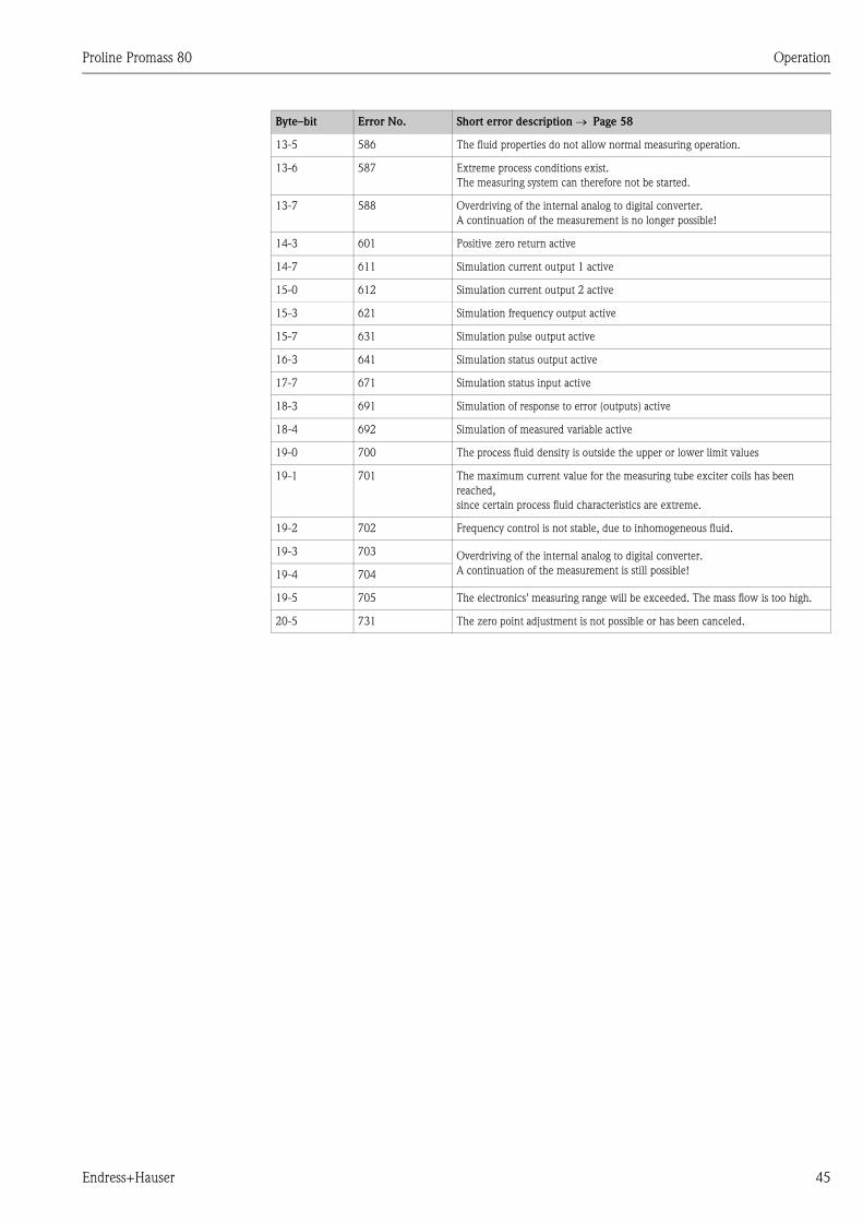
Proline Promass 80 Operation
Endress+Hauser 45
13-5 586 The fluid properties do not allow normal measuring operation.
13-6 587 Extreme process conditions exist.
The measuring system can therefore not be started.
13-7 588 Overdriving of the internal analog to digital converter.
A continuation of the measurement is no longer possible!
14-3 601 Positive zero return active
14-7 611 Simulation current output 1 active
15-0 612 Simulation current output 2 active
15-3 621 Simulation frequency output active
15-7 631 Simulation pulse output active
16-3 641 Simulation status output active
17-7 671 Simulation status input active
18-3 691 Simulation of response to error (outputs) active
18-4 692 Simulation of measured variable active
19-0 700 The process fluid density is outside the upper or lower limit values
19-1 701 The maximum current value for the measuring tube exciter coils has been
reached,
since certain process fluid characteristics are extreme.
19-2 702 Frequency control is not stable, due to inhomogeneous fluid.
19-3 703 Overdriving of the internal analog to digital converter.
A continuation of the measurement is still possible!19-4 704
19-5 705 The electronics' measuring range will be exceeded. The mass flow is too high.
20-5 731 The zero point adjustment is not possible or has been canceled.
Byte–bit Error No. Short error description → Page 58
Commissioning Proline Promass 80
46 Endress+Hauser
6 Commissioning
6.1 Function check
Make sure that all final checks have been completed before you start up your measuring point:
• Checklist for “Post installation check” → Page 23
• Checklist for “Post connection check” → Page 30
6.2 Switching on the measuring device
Once the post-connection checks have been successfully completed, it is time to switch on the
supply voltage. The device is now operational.
The measuring device performs a number of power on self-tests. As this procedure progresses the
following sequence of messages appears on the local display:
Normal measuring mode commences as soon as startup completes.
Various measured value and/or status variables appear on the display (HOME position).
! Note!
If startup fails, an error message indicating the cause is displayed.
PROMASS 80
START-UP...Startup message
DEVICE SOFTWARE
V XX.XX.XXCurrent software version
SYSTEM OK
→ OPERATIONBeginning of normal measuring mode
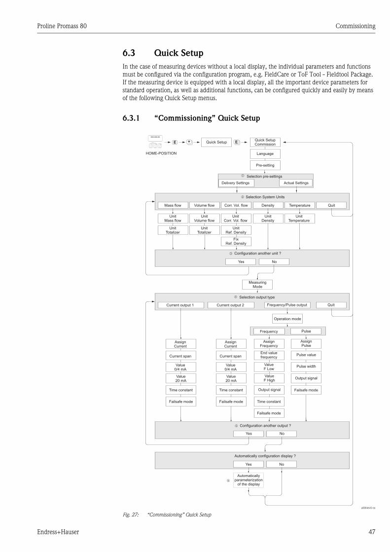
Proline Promass 80 Commissioning
Endress+Hauser 47
6.3 Quick Setup
In the case of measuring devices without a local display, the individual parameters and functions
must be configured via the configuration program, e.g. FieldCare or ToF Tool - Fieldtool Package.
If the measuring device is equipped with a local display, all the important device parameters for
standard operation, as well as additional functions, can be configured quickly and easily by means
of the following Quick Setup menus.
6.3.1 “Commissioning” Quick Setup
a0004645-en
Fig. 27: “Commissioning” Quick Setup
++ +E EEsc
E+-
XXX.XXX.XX
Yes
Yes
Yes
No
No
No
Mass flow
Current output 1
Volume flow Density
Frequency/Pulse output
Selection System Units
Selection output type
Configuration another unit ?
Configuration another output ?
Automatically configuration display ?
Temperature Quit
Quit
UnitMass flow
AssignCurrent
Current span
Value0/4 mA
Value20 mA
Time constant
Time constantFailsafe mode
Failsafe mode
Failsafe mode
AssignFrequency
End valuefrequency
ValueF Low
ValueF High
Output signal
AssignPulse
Pulse value
Pulse width
Output signal
UnitflowVolume
UnitDensity
Operation mode
UnitTemperature
MeasuringMode
UnitTotalizer
UnitTotalizer
Frequency Pulse
Automaticallyparameterization
of the display
Language
Pre-setting
Quick Setup
HOME-POSITION
Quick SetupCommission
AssignCurrent
Current span
Value0/4 mA
Value20 mA
Time constant
Failsafe mode
Current output 2
n
o
p
q
Corr. Vol. flow
UnitCorr. Vol. flow
UnitRef. Density
FixRef. Density
r
Selection pre-settings
Actual SettingsDeliver Settingsy
m

Commissioning Proline Promass 80
48 Endress+Hauser
! Note!
• The display returns to the cell SETUP COMMISSIONING if you press the X key combination
during an interrogation. The stored parameters remain valid.
m Selecting DELIVERY SETTINGS returns each selected unit to the factory setting.
Selecting ACTUAL SETTINGS applies the units you have set previously.
n Only units not yet configured in the current Setup are offered for selection in each cycle. The unit for mass, volume
and corrected volume is derived from the corresponding flow unit.
o The YES option remains visible until all the units have been configured. NO is the only option displayed when no
further units are available.
p Only the outputs not yet configured in the current Setup are offered for selection in each cycle.
q The YES option remains visible until all the outputs have been configured. NO is the only option displayed when
no further outputs are available.
r The “automatic parameterization of the display” option contains the following basic settings/factory settings:
YES: line 1= mass flow; line 2 = totalizer 1;
information line = operating/system conditions
NO: The existing (selected) settings remain.
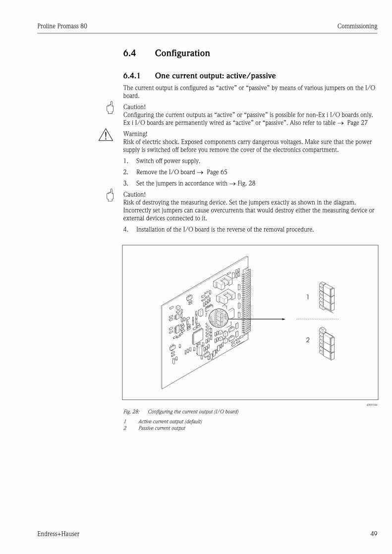
Proline Promass 80 Commissioning
Endress+Hauser 49
6.4 Configuration
6.4.1 One current output: active/passive
The current output is configured as “active” or “passive” by means of various jumpers on the I/O
board.
" Caution!
Configuring the current outputs as “active” or “passive” is possible for non-Ex i I/O boards only.
Ex i I/O boards are permanently wired as “active” or “passive”. Also refer to table → Page 27
# Warning!
Risk of electric shock. Exposed components carry dangerous voltages. Make sure that the power
supply is switched off before you remove the cover of the electronics compartment.
1. Switch off power supply.
2. Remove the I/O board → Page 65
3. Set the jumpers in accordance with → Fig. 28
" Caution!
Risk of destroying the measuring device. Set the jumpers exactly as shown in the diagram.
Incorrectly set jumpers can cause overcurrents that would destroy either the measuring device or
external devices connected to it.
4. Installation of the I/O board is the reverse of the removal procedure.
a0001044
Fig. 28: Configuring the current output (I/O board)
1 Active current output (default)
2 Passive current output
1
2
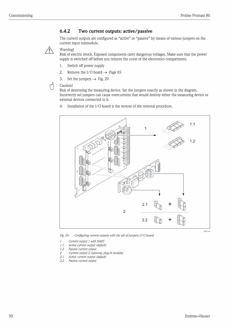
Commissioning Proline Promass 80
50 Endress+Hauser
6.4.2 Two current outputs: active/passive
The current outputs are configured as “active” or “passive” by means of various jumpers on the
current input submodule.
# Warning!
Risk of electric shock. Exposed components carry dangerous voltages. Make sure that the power
supply is switched off before you remove the cover of the electronics compartment.
1. Switch off power supply
2. Remove the I/O board → Page 65
3. Set the jumpers → Fig. 29
" Caution!
Risk of destroying the measuring device. Set the jumpers exactly as shown in the diagram.
Incorrectly set jumpers can cause overcurrents that would destroy either the measuring device or
external devices connected to it.
4. Installation of the I/O board is the reverse of the removal procedure.
a0001214
Fig. 29: Configuring current outputs with the aid of jumpers (I/O board)
1 Current output 1 with HART
1.1 Active current output (default)
1.2 Passive current output
2 Current output 2 (optional, plug-in module)
2.1 Active current output (default)
2.2 Passive current output
INPUT/O
UTPUT4
2
1
2.1
1.1
2.2
1.2
+
+
INPUT/O
UTPUT3
INPUT/O
UTPUT2
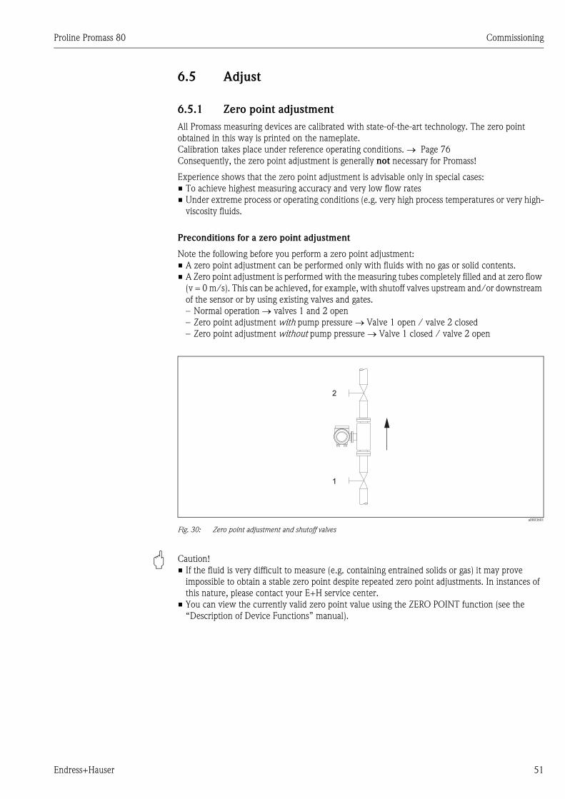
Proline Promass 80 Commissioning
Endress+Hauser 51
6.5 Adjust
6.5.1 Zero point adjustment
All Promass measuring devices are calibrated with state-of-the-art technology. The zero point
obtained in this way is printed on the nameplate.
Calibration takes place under reference operating conditions. → Page 76
Consequently, the zero point adjustment is generally not necessary for Promass!
Experience shows that the zero point adjustment is advisable only in special cases:
• To achieve highest measuring accuracy and very low flow rates
• Under extreme process or operating conditions (e.g. very high process temperatures or very high-
viscosity fluids.
Preconditions for a zero point adjustment
Note the following before you perform a zero point adjustment:
• A zero point adjustment can be performed only with fluids with no gas or solid contents.
• A Zero point adjustment is performed with the measuring tubes completely filled and at zero flow
(v = 0 m/s). This can be achieved, for example, with shutoff valves upstream and/or downstream
of the sensor or by using existing valves and gates.
– Normal operation → valves 1 and 2 open
– Zero point adjustment with pump pressure → Valve 1 open / valve 2 closed
– Zero point adjustment without pump pressure → Valve 1 closed / valve 2 open
a0003601
Fig. 30: Zero point adjustment and shutoff valves
" Caution!
• If the fluid is very difficult to measure (e.g. containing entrained solids or gas) it may prove
impossible to obtain a stable zero point despite repeated zero point adjustments. In instances of
this nature, please contact your E+H service center.
• You can view the currently valid zero point value using the ZERO POINT function (see the
“Description of Device Functions” manual).
1
2
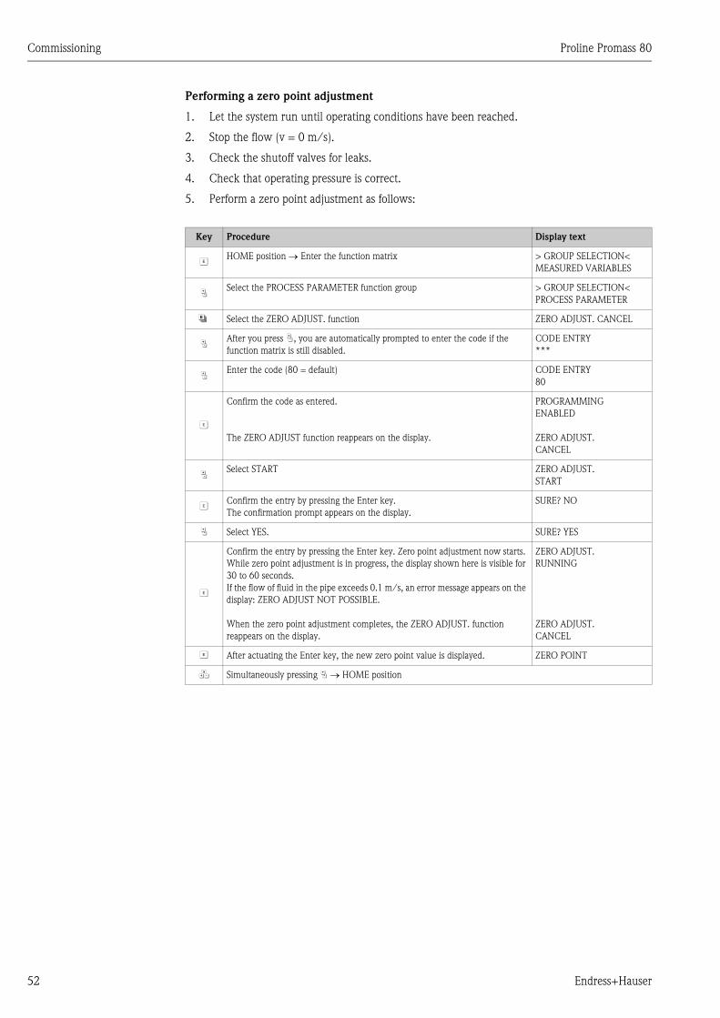
Commissioning Proline Promass 80
52 Endress+Hauser
Performing a zero point adjustment
1. Let the system run until operating conditions have been reached.
2. Stop the flow (v = 0 m/s).
3. Check the shutoff valves for leaks.
4. Check that operating pressure is correct.
5. Perform a zero point adjustment as follows:
Key Procedure Display text
FHOME position → Enter the function matrix > GROUP SELECTION<
MEASURED VARIABLES
PSelect the PROCESS PARAMETER function group > GROUP SELECTION<
PROCESS PARAMETER
N Select the ZERO ADJUST. function ZERO ADJUST. CANCEL
PAfter you press P, you are automatically prompted to enter the code if the
function matrix is still disabled.
CODE ENTRY
***
PEnter the code (80 = default) CODE ENTRY
80
F
Confirm the code as entered.
The ZERO ADJUST function reappears on the display.
PROGRAMMING
ENABLED
ZERO ADJUST.
CANCEL
PSelect START ZERO ADJUST.
START
FConfirm the entry by pressing the Enter key.
The confirmation prompt appears on the display.
SURE? NO
P Select YES. SURE? YES
F
Confirm the entry by pressing the Enter key. Zero point adjustment now starts.
While zero point adjustment is in progress, the display shown here is visible for
30 to 60 seconds.
If the flow of fluid in the pipe exceeds 0.1 m/s, an error message appears on the
display: ZERO ADJUST NOT POSSIBLE.
When the zero point adjustment completes, the ZERO ADJUST. function
reappears on the display.
ZERO ADJUST.
RUNNING
ZERO ADJUST.
CANCEL
F After actuating the Enter key, the new zero point value is displayed. ZERO POINT
Q Simultaneously pressing P → HOME position
Proline Promass 80 Commissioning
Endress+Hauser 53
6.5.2 Density adjustment
Measuring accuracy in determining fluid density has a direct effect on calculating volume flow.
Density adjustment, therefore, is necessary under the following circumstances:
• The sensor does not measure exactly the density value that the user expects, based on laboratory
analyses.
• The fluid properties are outside the measuring points set at the factory, or the reference operating
conditions used to calibrate the measuring device.
• The system is used exclusively to measure a fluid’s density which must be registered to a high
degree of accuracy under constant conditions.
Performing a 1-point or 2-point density adjustment
" Caution!
• Onsite density adjustment can be performed only if the user has detailed knowledge of the fluid
density, obtained for example from detailed laboratory analyses.
• The target density value specified in this way must not deviate from the measured fluid density
by more than ±10%.
• An error in defining the target density affects all calculated density and volume functions.
• Density adjustment changes the factory density calibration values or the calibration values set by
the service technician.
• The functions outlined in the following instructions are described in detail in the “Description of
Device Functions” manual.
1. Fill the sensor with fluid. Make sure that the measuring tubes are completely filled and that
liquids are free of gas bubbles.
2. Wait until the temperature difference between fluid and measuring tube has equalized. The
time you have to wait for equalization depends on the fluid and the temperature level.
3. Select the density adjustment function:
HOME → F → R → PROCESS PARAMETERS → F → DENSITY SET POINT
– When you press P you are automatically prompted to enter the access code if the function
matrix is still disabled. Enter the code.
– Use P to enter the fluid's target density and press F to save this value (input range = actual
density value ±10%).
4. Press F to select the MEASURE FLUID function.
Use P to select the setting START and press F. The message DENSITY ADJUST RUNNING
then appears on the display for 10 seconds. During this time Promass measures the current
density of the fluid (measured density value).
5. Press F and select the DENSITY ADJUST function.
Now use P to select the setting DENSITY ADJUST and press F. Promass compares the
measured density value with the specified value and calculates the new density coefficient.
" Caution!
If a density adjustment does not complete correctly, you can select the RESTORE ORIGINAL
function to reactivate the default density coefficient.
6. Use Q Use Q to return to the HOME position (press P simultaneously).
Commissioning Proline Promass 80
54 Endress+Hauser
6.6 Purge and pressure monitoring connections
The sensor housing protects the inner electronics and mechanics and is filled with dry nitrogen.
Beyond that, up to a specified measuring pressure it additionally serves as secondary containment.
# Warning!
For a process pressure above the specified containment pressure, the housing does not serve as an
additional secondary containment. In case a danger of measuring tube failure exists due to process
characteristics, e.g. with corrosive process fluids, we recommend the use of sensors whose housing
is equipped with special pressure monitoring connections (ordering option). With the help of these
connections, fluid collected in the housing in the event of tube failure can be drained off. This
diminishes the danger of mechanical overload of the housing, which could lead to a housing failure
and accordingly is connected with an increased danger potential. These connections can also be
used for gas purging (gas detection).
The following instructions apply to handling sensors with purge or pressure monitoring connections:
• Do not open the purge connections unless the containment can be filled immediately with a dry
inert gas.
• Use only low gauge pressure to purge. Maximum pressure 5 bar.
6.7 Data storage device (HistoROM)
At Endress+Hauser, the term HistoROM refers to various types of data storage modules on which
process and measuring device data are stored. By plugging and unplugging such modules, device
configurations can be duplicated onto other measuring devices to cite just one example.
6.7.1 HistoROM/S–DAT (sensor–DAT)
The S-DAT is an exchangeable data storage device in which all sensor relevant parameters are
stored, i.e., diameter, serial number, calibration factor, zero point.
Proline Promass 80 Maintenance
Endress+Hauser 55
7 Maintenance
No special maintenance work is required.
7.1 Exterior cleaning
When cleaning the exterior of measuring devices, always use cleaning agents that do not attack the
surface of the housing and the seals.
7.2 Cleaning with pigs (Promass H, I)
If pigs are used for cleaning, it is essential to take the inside diameters of measuring tube and process
connection into account. See also Technical Information. → Page 96
7.3 Replacing seals
Under normal circumstances, fluid wetted seals of the Promass A and Promass M sensors do not
require replacement. Replacement is necessary only in special circumstances, for example if
aggressive or corrosive fluids are incompatible with the seal material.
! Note!
• The period between changes depends on the fluid properties and on the frequency of cleaning
cycles in the case of CIP/SIP cleaning.
• Replacement seals (accessories)
Accessories Proline Promass 80
56 Endress+Hauser
8 Accessories
Various accessories, which can be ordered separately from Endress+Hauser, are available for the
transmitter and the sensor. The Endress+Hauser service organization can provide detailed
information on the order code of your choice.
8.1 Device-specific accessories:
8.2 Measuring principle-specific accessories:
8.3 Communication-specific accessories:
Accessory Description Order code
Proline Promass 80
transmitter
Transmitter for replacement or for stock. Use the order
code to define the following specifications:
– Approvals
– Degree of protection / version
– Cable entries
– Display / power supply / operation
– Software
– Outputs / inputs
80XXX – XXXXX * * * * * *
Accessory Description Order code
Mounting set for
transmitter
Mounting set for remote version. Suitable for:
– Wall mounting
– Pipe mounting
– Installation in control panel
Mounting set for aluminum field housing:
Suitable for pipe mounting (3/4" to 3")
DK8WM – *
Post mounting set for the
Promass A sensor
Post mounting set for the Promass A DK8AS – * *
Mounting set for the
Promass A sensor
Mounting set for Promass A, comprising:
– 2 process connections
– Seals
DK8MS – * * * * * *
Set of seals for sensor For regular replacement of the seals of the Promass M and
Promass A sensors.
Set consists of two seals.
DKS – * * *
Accessory Description Order code
HART Communicator
DXR 375 handheld
terminal
Handheld terminal for remote configuration and for
obtaining measured values via the current output HART
(4 to 20 mA).
Contact your Endress+Hauser representative for more
information.
DXR375 – * * * *
Proline Promass 80 Accessories
Endress+Hauser 57
8.4 Service-specific accessories:
Accessory Description Order code
Applicator Software for selecting and configuring flowmeters.
Applicator can be downloaded from the Internet or
ordered on CD-ROM for installation on a local PC.
Contact your Endress+Hauser representative for more
information.
DKA80 – *
ToF Tool – Fieldtool
Package
Modular software package consisting of the service
program “ToF Tool” for configuration and diagnosis of
ToF level measuring devices (time-of-flight
measurement) and the “Fieldtool” service program for
the configuration and diagnosis of Proline flow measuring
devices. The Proline flow measuring devices are accessed
via a service interface or via the service interface
FXA 193.
Contents of the “ToF Tool – Fieldtool Package”:
– Commissioning, maintenance analysis
– Configuring flowmeters
– Service functions
– Visualization of process data
– Troubleshooting
– Access to the verification data and updating the
software of the “Fieldcheck” flow simulator
Contact your Endress+Hauser representative for more
information.
DXS10 – * * * * *
Fieldcheck Tester/simulator for testing flowmeters in the field.
When used in conjunction with the “ToF Tool –
Fieldtool Package” software package, test results can be
imported into a database, printed and used for official
certification.
Contact your Endress+Hauser representative for more
information.
50098801
Troubleshooting Proline Promass 80
58 Endress+Hauser
9 Troubleshooting
9.1 Troubleshooting instructions
Always start troubleshooting with the following checklist if faults occur after commissioning or
during operation. The routine takes you directly to the cause of the problem and the appropriate
remedial measures.
Check the display
No display visible and no
output signals present.
1. Check the supply voltage → Terminals 1, 2
2. Check device fuse → Page 70
85 to 260 V AC: 0.8 A slow-blow / 250 V
20 to 55 V AC and 16 to 62 V DC: 2 A slow-blow / 250 V
3. Measuring electronics defective → order spare parts
→ Page 65
No display visible, but
output signals are present.
1. Check whether the ribbon-cable connector of the display module is correctly plugged
into the amplifier board → Page 65
2. Display module defective → order spare parts → Page 65
3. Measuring electronics defective → order spare parts → Page 65
Display texts are in a
foreign language.
Switch off power supply. Press and hold down both the P keys and switch on the
measuring device. The display text will appear in English (default) and is displayed at
maximum contrast.
Measured value indicated,
but no signal at the current
or pulse output
Measuring electronics defective → order spare parts → Page 65
Error messages on display
Errors that occur during commissioning or measuring are displayed immediately. Error messages consist of a variety of
icons. The meanings of these icons are as follows (example):
– Error type: S = system error, P = process error
– Error message type: $ = fault message, ! = notice message
– MEDIUM INHOM. = error designation (e.g. fluid is not homogeneous)
– 03:00:05 = duration of error occurrence (in hours, minutes and seconds)
– #702 = error number
" Caution!
• See the information on → Page 34
• The measuring system interprets simulations and positive zero return as system errors, but displays them as notice
messages only.
Other error (without error message)
Some other error has
occurred.
Diagnosis and rectification → Page 63
Proline Promass 80 Troubleshooting
Endress+Hauser 59
9.2 System error messages
Serious system errors are always recognized by the instrument as a “Fault message” and are shown
as a lightning flash ($) on the display! Fault messages immediately affect the inputs and outputs.
Simulations and positive zero return, on the other hand, are classed and displayed as “Notice
messages”.
" Caution!
In the event of a serious fault, a flowmeter might have to be returned to the manufacturer for repair.
Important procedures must be carried out before you return a flowmeter to Endress+Hauser.
→ Page 8
Always enclose a duly completed “Declaration of contamination” form. You will find a preprinted
blank of this form at the back of this manual.
! Note!
• The error types listed in the following correspond to the factory settings.
• See the information on → Page 34
No. Error message / Type Cause Remedy / spare part
S = System error
$ = Fault message (with an effect on the outputs)
! = Notice message (without an effect on the outputs)
No. # 0xx → Hardware error
001 S: CRITICAL FAILURE
$: # 001
Serious device error Replace the amplifier board. Spare part → Page 65
011 S: AMP HW EEPROM
$: # 011
Amplifier:
Defective EEPROM
Replace the amplifier board. Spare parts → Page 65
012 S: AMP SW EEPROM
$: # 012
Measuring amplifier: Error when accessing data of the
EEPROM
The EEPROM data blocks in which an error has occurred are
displayed in the TROUBLESHOOTING function.
Press Enter to acknowledge the errors in question; default values
are automatically inserted instead of the erroneous parameter
values.
! Note!
The measuring device has to be restarted if an error has occurred
in a totalizer block (see error No. 111/CHECKSUM TOTAL.).
031 S: SENSOR HW DAT
$: # 031
Sensor DAT:
1. S-DAT is defective.
2. S-DAT is not plugged into the amplifier board or is
missing.
1. Replace the S-DAT.
Spare parts → Page 65
Check the spare part set number to ensure that the new,
replacement DAT is compatible with the measuring
electronics.
– Plug the S-DAT into the amplifier board
→ Page 67 → Page 69
032 S: SENSOR SW DAT
$: # 032
Sensor DAT:
Error accessing the calibration values stored in the S-
DAT.
– Check whether the S-DAT is correctly plugged into the
amplifier board → Page 67 → Page 69
2. Replace the S-DAT if it is defective. Spare parts → Page 65
Before replacing the DAT, check that the new, replacement
DAT is compatible with the measuring electronics. Check
the:
– Spare part set number
– Hardware revision code
3. Replace measuring electronics boards if necessary.
Spare parts → Page 65
051 A / C COMPATIB.
$: # 051
The I/O board and the amplifier board are not
compatible.
Use only compatible modules and boards.
Check the compatibility of the modules used.
Check the:
– Spare part set number
– Hardware revision code
No. # 1xx → Software error
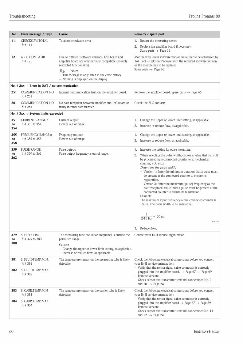
Troubleshooting Proline Promass 80
60 Endress+Hauser
111 CHECKSUM TOTAL
$: # 111
Totalizer checksum error 1. Restart the measuring device
2. Replace the amplifier board if necessary.
Spare parts → Page 65
121 A / C COMPATIB.
!: # 121
Due to different software versions, I/O board and
amplifier board are only partially compatible (possibly
restricted functionality).
! Note!
– This message is only listed in the error history.
– Nothing is displayed on the display.
Module with lower software version has either to be actualized by
ToF Tool – Fieldtool Package with the required software version
or the module has to be replaced.
Spare parts → Page 65
No. # 2xx → Error in DAT / no communication
251 COMMUNICATION I/O
$: # 251
Internal communication fault on the amplifier board. Remove the amplifier board. Spare parts → Page 65
261 COMMUNICATION I/O
$: # 261
No data reception between amplifier and I/O board or
faulty internal data transfer.
Check the BUS contacts
No. # 3xx → System limits exceeded
351
to
354
CURRENT RANGE n
!: # 351 to 354
Current output:
Flow is out of range.
1. Change the upper or lower limit setting, as applicable.
2. Increase or reduce flow, as applicable.
355
to
358
FREQUENCY RANGE n
!: # 355 to 358
Frequency output:
Flow is out of range.
1. Change the upper or lower limit setting, as applicable.
2. Increase or reduce flow, as applicable.
359
to
362
PULSE RANGE
!: # 359 to 362
Pulse output:
Pulse output frequency is out of range.
1. Increase the setting for pulse weighting
2. When selecting the pulse width, choose a value that can still
be processed by a connected counter (e.g. mechanical
counter, PLC etc.).
Determine the pulse width:
– Version 1: Enter the minimum duration that a pulse must
be present at the connected counter to ensure its
registration.
– Version 2: Enter the maximum (pulse) frequency as the
half “reciprocal value” that a pulse must be present at the
connected counter to ensure its registration.
Example:
The maximum input frequency of the connected counter is
10 Hz. The pulse width to be entered is:
a0004437
3. Reduce flow.
379
to
380
S: FREQ. LIM
$: # 379 to 380
The measuring tube oscillation frequency is outside the
permitted range.
Causes:
– Change the upper or lower limit setting, as applicable.
– Increase or reduce flow, as applicable.
Contact your E+H service organization.
381 S: FLUIDTEMP.MIN.
$: # 381
The temperature sensor on the measuring tube is likely
defective.
Check the following electrical connections before you contact
your E+H service organization:
– Verify that the sensor signal cable connector is correctly
plugged into the amplifier board. → Page 67 → Page 69
– Remote version:
Check sensor and transmitter terminal connections No. 9
and 10. → Page 24
382 S: FLUIDTEMP.MAX.
$: # 382
383 S: CARR.TEMP.MIN
$: # 383
The temperature sensor on the carrier tube is likely
defective.
Check the following electrical connections before you contact
your E+H service organization:
– Verify that the sensor signal cable connector is correctly
plugged into the amplifier board → Page 67 → Page 69
– Remote version:
Check sensor and transmitter terminal connections No. 11
and 12. → Page 24
384 S: CARR.TEMP.MAX
$: # 384
No. Error message / Type Cause Remedy / spare part
1
2.10 Hz= 50 ms
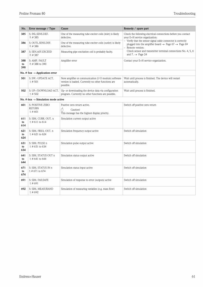
Proline Promass 80 Troubleshooting
Endress+Hauser 61
385 S: INL.SENS.DEF.
$: # 385
One of the measuring tube exciter coils (inlet) is likely
defective.
Check the following electrical connections before you contact
your E+H service organization:
– Verify that the sensor signal cable connector is correctly
plugged into the amplifier board → Page 67 → Page 69
– Remote version:
Check sensor and transmitter terminal connections No. 4, 5, 6
and 7. → Page 24
386 S: OUTL.SENS.DEF.
$: # 386
One of the measuring tube exciter coils (outlet) is likely
defective.
387 S: SEN.ASY.EXCEED
$: # 387
Measuring pipe excitation coil is probably faulty.
388
to
390
S: AMP. FAULT
$: # 388 to 390
Amplifier error Contact your E+H service organization.
No. # 5xx → Application error
501 S: SW.–UPDATE ACT.
!: # 501
New amplifier or communication (I/O module) software
version is loaded. Currently no other functions are
possible.
Wait until process is finished. The device will restart
automatically.
502 S: UP-/DOWNLOAD ACT.
!: # 502
Up- or downloading the device data via configuration
program. Currently no other functions are possible.
Wait until process is finished.
No. # 6xx → Simulation mode active
601 S: POSITIVE ZERO
RETURN
!: # 601
Positive zero return active.
" Caution!
This message has the highest display priority.
Switch off positive zero return
611
to
614
S: SIM. CURR. OUT. n
!: # 611 to 614
Simulation current output active
621
to
624
S: SIM. FREQ. OUT. n
!: # 621 to 624
Simulation frequency output active Switch off simulation
631
to
634
S: SIM. PULSE n
!: # 631 to 634
Simulation pulse output active Switch off simulation
641
to
644
S: SIM. STATUS OUT n
!: # 641 to 644
Simulation status output active Switch off simulation
671
to
674
S: SIM. STATUS IN n
!: # 671 to 674
Simulation status input active Switch off simulation
691 S: SIM. FAILSAFE
!: # 691
Simulation of response to error (outputs) active Switch off simulation
692 S: SIM. MEASURAND
!: # 692
Simulation of measuring variables (e.g. mass flow) Switch off simulation
No. Error message / Type Cause Remedy / spare part
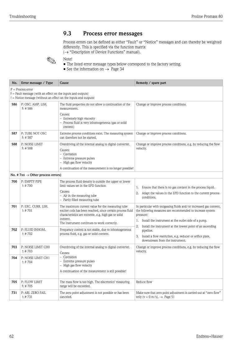
Troubleshooting Proline Promass 80
62 Endress+Hauser
9.3 Process error messages
Process errors can be defined as either “Fault” or “Notice” messages and can thereby be weighted
differently. This is specified via the function matrix
(→ “Description of Device Functions” manual).
! Note!
• The listed error message types below correspond to the factory setting.
• See the information on → Page 34
No. Error message / Type Cause Remedy / spare part
P = Process error
$ = Fault message (with an effect on the inputs and outputs)
! = Notice message (without an effect on the inputs and outputs)
586 P: OSC. AMP. LIM.
$: # 586
The fluid properties do not allow a continuation of the
measurement.
Causes:
– Extremely high viscosity
– Process fluid is very inhomogeneous (gas or solid
content)
Change or improve process conditions.
587 P: TUBE NOT OSC
$: # 587
Extreme process conditions exist. The measuring system
can therefore not be started.
Change or improve process conditions.
588 P: NOISE LIMIT
$: # 588
Overdriving of the internal analog to digital converter.
Causes:
– Cavitation
– Extreme pressure pulses
– High gas flow velocity
A continuation of the measurement is no longer possible!
Change or improve process conditions, e.g. by reducing the flow
velocity.
No. # 7xx → Other process errors)
700 P: EMPTY PIPE
!: # 700
The process fluid density is outside the upper or lower
limit values set in the EPD function
Causes:
– Air in the measuring tube
– Partly filled measuring tube
1. Ensure that there is no gas content in the process liquid.
2. Adapt the values in the EPD function to the current process
conditions.
701 P: EXC. CURR. LIM.
!: # 701
The maximum current value for the measuring tube
exciter coils has been reached, since certain process fluid
characteristics are extreme, e.g. high gas or solid
content.
The instrument continues to work correctly.
In particular with outgassing fluids and/or increased gas content,
the following measures are recommended to increase system
pressure:
1. Install the instrument at the outlet side of a pump.
2. Install the instrument at the lowest point of an ascending
pipeline.
3. Install a flow restriction, e.g. reducer or orifice plate,
downstream from the instrument.
702 P: FLUID INHOM.
!: # 702
Frequency control is not stable, due to inhomogeneous
process fluid, e.g. gas or solid content.
703 P: NOISE LIMIT CH0
!: # 703
Overdriving of the internal analog to digital converter.
Causes:
– Cavitation
– Extreme pressure pulses
– High gas flow velocity
A continuation of the measurement is still possible!
Change or improve process conditions, e.g. by reducing the flow
velocity.
704 P: NOISE LIMIT CH1
!: # 704
705 P: FLOW LIMIT
$: # 705
The mass flow is too high. The electronics' measuring
range will be exceeded.
Reduce flow
731 P: ABJ. ZERO FAIL
!: # 731
The zero point adjustment is not possible or has been
canceled.
Make sure that zero point adjustment is carried out at “zero flow”
only (v = 0 m/s). → Page 51
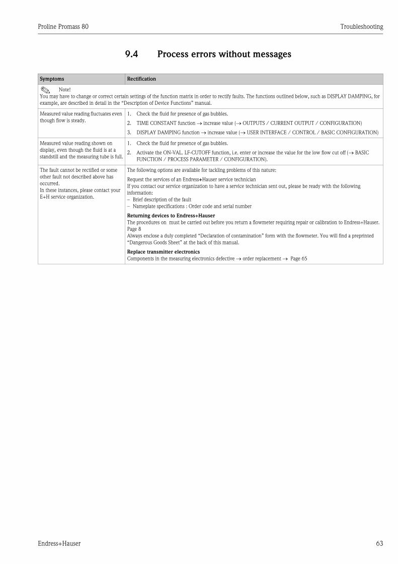
Proline Promass 80 Troubleshooting
Endress+Hauser 63
9.4 Process errors without messages
Symptoms Rectification
! Note!
You may have to change or correct certain settings of the function matrix in order to rectify faults. The functions outlined below, such as DISPLAY DAMPING, for
example, are described in detail in the “Description of Device Functions” manual.
Measured value reading fluctuates even
though flow is steady.
1. Check the fluid for presence of gas bubbles.
2. TIME CONSTANT function → increase value (→ OUTPUTS / CURRENT OUTPUT / CONFIGURATION)
3. DISPLAY DAMPING function → increase value (→ USER INTERFACE / CONTROL / BASIC CONFIGURATION)
Measured value reading shown on
display, even though the fluid is at a
standstill and the measuring tube is full.
1. Check the fluid for presence of gas bubbles.
2. Activate the ON-VAL. LF-CUTOFF function, i.e. enter or increase the value for the low flow cut off (→ BASIC
FUNCTION / PROCESS PARAMETER / CONFIGURATION).
The fault cannot be rectified or some
other fault not described above has
occurred.
In these instances, please contact your
E+H service organization.
The following options are available for tackling problems of this nature:
Request the services of an Endress+Hauser service technician
If you contact our service organization to have a service technician sent out, please be ready with the following
information:
– Brief description of the fault
– Nameplate specifications : Order code and serial number
Returning devices to Endress+Hauser
The procedures on must be carried out before you return a flowmeter requiring repair or calibration to Endress+Hauser.
Page 8
Always enclose a duly completed “Declaration of contamination” form with the flowmeter. You will find a preprinted
“Dangerous Goods Sheet” at the back of this manual.
Replace transmitter electronics
Components in the measuring electronics defective → order replacement → Page 65
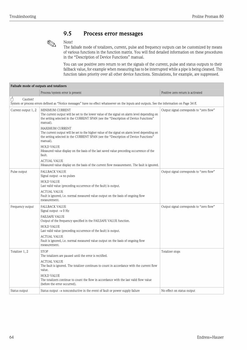
Troubleshooting Proline Promass 80
64 Endress+Hauser
9.5 Process error messages
! Note!
The failsafe mode of totalizers, current, pulse and frequency outputs can be customized by means
of various functions in the function matrix. You will find detailed information on these procedures
in the “Description of Device Functions” manual.
You can use positive zero return to set the signals of the current, pulse and status outputs to their
fallback value, for example when measuring has to be interrupted while a pipe is being cleaned. This
function takes priority over all other device functions. Simulations, for example, are suppressed.
Failsafe mode of outputs and totalizers
Process/system error is present Positive zero return is activated
" Caution!
System or process errors defined as “Notice messages” have no effect whatsoever on the inputs and outputs. See the information on Page 34 ff.
Current output 1, 2 MINIMUM CURRENT
The current output will be set to the lower value of the signal on alarm level depending on
the setting selected in the CURRENT SPAN (see the “Description of Device Functions”
manual).
MAXIMUM CURRENT
The current output will be set to the higher value of the signal on alarm level depending on
the setting selected in the CURRENT SPAN (see the “Description of Device Functions”
manual).
HOLD VALUE
Measured value display on the basis of the last saved value preceding occurrence of the
fault.
ACTUAL VALUE
Measured value display on the basis of the current flow measurement. The fault is ignored.
Output signal corresponds to “zero flow”
Pulse output FALLBACK VALUE
Signal output → no pulses
HOLD VALUE
Last valid value (preceding occurrence of the fault) is output.
ACTUAL VALUE
Fault is ignored, i.e. normal measured value output on the basis of ongoing flow
measurement.
Output signal corresponds to “zero flow”
Frequency output FALLBACK VALUE
Signal output → 0 Hz
FAILSAFE VALUE
Output of the frequency specified in the FAILSAFE VALUE function.
HOLD VALUE
Last valid value (preceding occurrence of the fault) is output.
ACTUAL VALUE
Fault is ignored, i.e. normal measured value output on the basis of ongoing flow
measurement.
Output signal corresponds to “zero flow”
Totalizer 1, 2 STOP
The totalizers are paused until the error is rectified.
ACTUAL VALUE
The fault is ignored. The totalizer continues to count in accordance with the current flow
value.
HOLD VALUE
The totalizers continue to count the flow in accordance with the last valid flow value
(before the error occurred).
Totalizer stops
Status output Status output → nonconductive in the event of fault or power supply failure No effect on status output
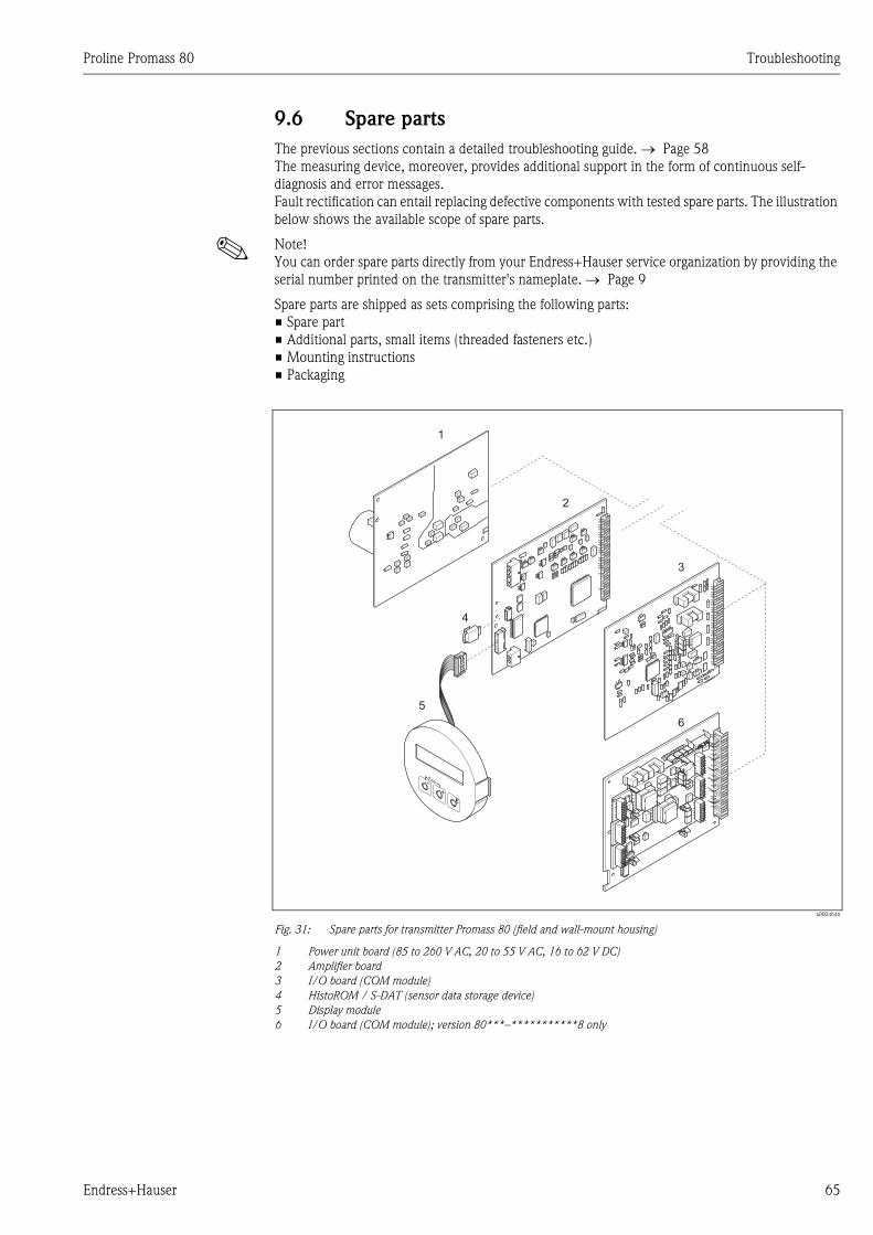
Proline Promass 80 Troubleshooting
Endress+Hauser 65
9.6 Spare parts
The previous sections contain a detailed troubleshooting guide. → Page 58
The measuring device, moreover, provides additional support in the form of continuous self-
diagnosis and error messages.
Fault rectification can entail replacing defective components with tested spare parts. The illustration
below shows the available scope of spare parts.
! Note!
You can order spare parts directly from your Endress+Hauser service organization by providing the
serial number printed on the transmitter's nameplate. → Page 9
Spare parts are shipped as sets comprising the following parts:
• Spare part
• Additional parts, small items (threaded fasteners etc.)
• Mounting instructions
• Packaging
a0004646
Fig. 31: Spare parts for transmitter Promass 80 (field and wall-mount housing)
1 Power unit board (85 to 260 V AC, 20 to 55 V AC, 16 to 62 V DC)
2 Amplifier board
3 I/O board (COM module)
4 HistoROM / S-DAT (sensor data storage device)
5 Display module
6 I/O board (COM module); version 80***–***********8 only
1
2
4
5
3
6
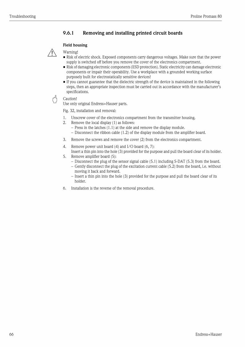
Troubleshooting Proline Promass 80
66 Endress+Hauser
9.6.1 Removing and installing printed circuit boards
Field housing
# Warning!
• Risk of electric shock. Exposed components carry dangerous voltages. Make sure that the power
supply is switched off before you remove the cover of the electronics compartment.
• Risk of damaging electronic components (ESD protection). Static electricity can damage electronic
components or impair their operability. Use a workplace with a grounded working surface
purposely built for electrostatically sensitive devices!
• If you cannot guarantee that the dielectric strength of the device is maintained in the following
steps, then an appropriate inspection must be carried out in accordance with the manufacturer’s
specifications.
" Caution!
Use only original Endress+Hauser parts.
Fig. 32, installation and removal:
1. Unscrew cover of the electronics compartment from the transmitter housing.
2. Remove the local display (1) as follows:
– Press in the latches (1.1) at the side and remove the display module.
– Disconnect the ribbon cable (1.2) of the display module from the amplifier board.
3. Remove the screws and remove the cover (2) from the electronics compartment.
4. Remove power unit board (4) and I/O board (6, 7):
Insert a thin pin into the hole (3) provided for the purpose and pull the board clear of its holder.
5. Remove amplifier board (5):
– Disconnect the plug of the sensor signal cable (5.1) including S-DAT (5.3) from the board.
– Gently disconnect the plug of the excitation current cable (5.2) from the board, i.e. without
moving it back and forward.
– Insert a thin pin into the hole (3) provided for the purpose and pull the board clear of its
holder.
6. Installation is the reverse of the removal procedure.
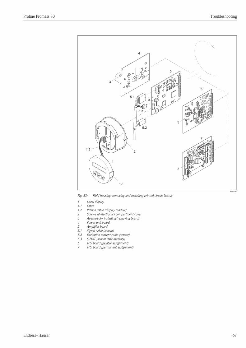
Proline Promass 80 Troubleshooting
Endress+Hauser 67
a0004647
Fig. 32: Field housing: removing and installing printed circuit boards
1 Local display
1.1 Latch
1.2 Ribbon cable (display module)
2 Screws of electronics compartment cover
3 Aperture for installing/removing boards
4 Power unit board
5 Amplifier board
5.1 Signal cable (sensor)
5.2 Excitation current cable (sensor)
5.3 S-DAT (sensor data memory)
6 I/O board (flexible assignment)
7 I/O board (permanent assignment)
3
3
3
4
5
6
2
1
1.2
5.1
5.3
5.2
1.1
7
3
Troubleshooting Proline Promass 80
68 Endress+Hauser
Wall-mount housing
# Warning!
• Risk of electric shock. Exposed components carry dangerous voltages. Make sure that the power
supply is switched off before you remove the cover of the electronics compartment.
• Risk of damaging electronic components (ESD protection). Static electricity can damage electronic
components or impair their operability. Use a workplace with a grounded working surface
purposely built for electrostatically sensitive devices!
• If you cannot guarantee that the dielectric strength of the device is maintained in the following
steps, then an appropriate inspection must be carried out in accordance with the manufacturer’s
specifications.
" Caution!
Use only original Endress+Hauser parts.
Fig. 33, installation and removal:
1. Remove the screws and open the hinged cover (1) of the housing.
2. Remove the screws securing the electronics module (2). Then push up electronics module and
pull it as far as possible out of the wall-mount housing.
3. Disconnect the following cable plugs from amplifier board (7):
– Sensor signal cable plug (7.1) including S-DAT (7.3)
– Unplug excitation current cable (7.2). Gently disconnect the plug, i.e. without moving it
back and forward.
– Ribbon cable (3) of the display module
4. Remove the screws and remove the cover (4) from the electronics compartment.
5. Remove the boards (6, 7, 8, 9):
Insert a thin pin into the hole (5) provided for the purpose and pull the board clear of its holder.
6. Installation is the reverse of the removal procedure.
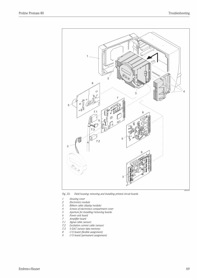
Proline Promass 80 Troubleshooting
Endress+Hauser 69
a0004648
Fig. 33: Field housing: removing and installing printed circuit boards
1 Housing cover
2 Electronics module
3 Ribbon cable (display module)
4 Screws of electronics compartment cover
5 Aperture for installing/removing boards
6 Power unit board
7 Amplifier board
7.1 Signal cable (sensor)
7.2 Excitation current cable (sensor)
7.3 S-DAT (sensor data memory)
8 I/O board (flexible assignment)
9 I/O board (permanent assignment)
6
7
8
5
5
5
34
7.1
7.3
7.2
1
2
3
9
3
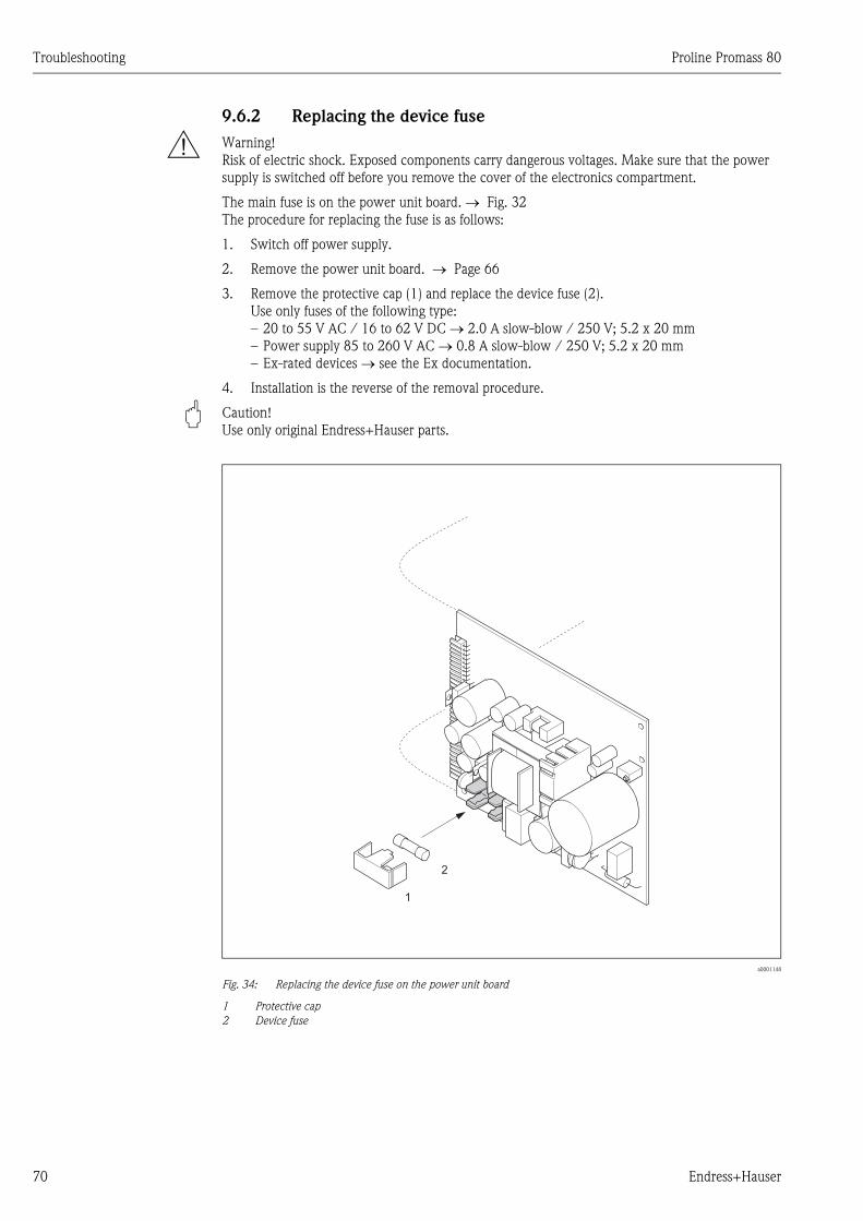
Troubleshooting Proline Promass 80
70 Endress+Hauser
9.6.2 Replacing the device fuse
# Warning!
Risk of electric shock. Exposed components carry dangerous voltages. Make sure that the power
supply is switched off before you remove the cover of the electronics compartment.
The main fuse is on the power unit board. → Fig. 32
The procedure for replacing the fuse is as follows:
1. Switch off power supply.
2. Remove the power unit board. → Page 66
3. Remove the protective cap (1) and replace the device fuse (2).
Use only fuses of the following type:
– 20 to 55 V AC / 16 to 62 V DC → 2.0 A slow-blow / 250 V; 5.2 x 20 mm
– Power supply 85 to 260 V AC → 0.8 A slow-blow / 250 V; 5.2 x 20 mm
– Ex-rated devices → see the Ex documentation.
4. Installation is the reverse of the removal procedure.
" Caution!
Use only original Endress+Hauser parts.
a0001148
Fig. 34: Replacing the device fuse on the power unit board
1 Protective cap
2 Device fuse
1
2
Proline Promass 80 Troubleshooting
Endress+Hauser 71
9.7 Return
The following procedures must be carried out before a flowmeter requiring repair or calibration, for
example, is returned to Endress+Hauser:
• Always enclose a duly completed “Declaration of contamination” form. Only then can
Endress+Hauser transport, examine and repair a returned device.
• Enclose special handling instructions if necessary, such as a safety data sheet as per EN 91/155/
EEC.
• Remove all residues. Pay special attention to the grooves for seals and crevices which could
contain residues. This is particularly important if the substance is hazardous to health, i.e. if it is
flammable, toxic, caustic, carcinogenic etc.
With Promass A and Promass M, the threaded process connections must be removed from the
sensor first and then cleaned.
! Note!
You will find a preprinted “Declaration of contamination” form at the back of this manual.
# Warning!
• Do not return a measuring device if you are not absolutely certain that all traces of hazardous
substances have been removed, e.g. substances which have penetrated crevices or diffused
through plastic.
• Costs incurred for waste disposal and injury (burns etc.) due to inadequate cleaning will be
charged to the owner-operator.
9.8 Disposal
Observe the regulations applicable in your country!
9.9 Software history
! Note!
Up or downloading a software version normally requires a special service software.
Date Software version Changes to software Operating
Instructions
11.2005 2.01.XX Software expansion:
– Promass I DN80, DN50FB
– General instrument functions
71008475/12.05
11.2004 2.00.XX Software expansion:
– New sensor DN 250
– Chinese language package (English and
Chinese contents)
New functions:
– Empty pipe detection via exciting current
(EPD EXC.CURR.MAX (6426))
– DEVICE SOFTWARE (8100) → Display
of the device software (NAMUR
recommendation 53)
50098468/11.04
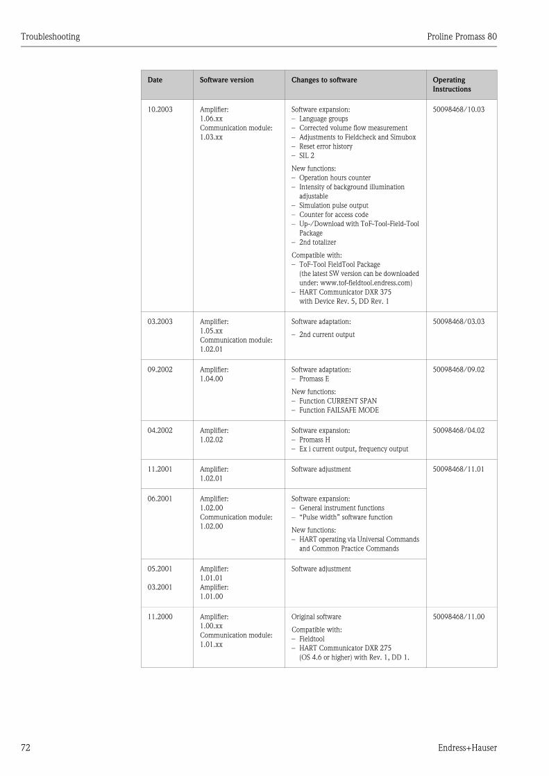
Troubleshooting Proline Promass 80
72 Endress+Hauser
10.2003 Amplifier:
1.06.xx
Communication module:
1.03.xx
Software expansion:
– Language groups
– Corrected volume flow measurement
– Adjustments to Fieldcheck and Simubox
– Reset error history
– SIL 2
New functions:
– Operation hours counter
– Intensity of background illumination
adjustable
– Simulation pulse output
– Counter for access code
– Up-/Download with ToF-Tool-Field-Tool
Package
– 2nd totalizer
Compatible with:
– ToF-Tool FieldTool Package
(the latest SW version can be downloaded
under: www.tof-fieldtool.endress.com)
– HART Communicator DXR 375
with Device Rev. 5, DD Rev. 1
50098468/10.03
03.2003 Amplifier:
1.05.xx
Communication module:
1.02.01
Software adaptation:
– 2nd current output
50098468/03.03
09.2002 Amplifier:
1.04.00
Software adaptation:
– Promass E
New functions:
– Function CURRENT SPAN
– Function FAILSAFE MODE
50098468/09.02
04.2002 Amplifier:
1.02.02
Software expansion:
– Promass H
– Ex i current output, frequency output
50098468/04.02
11.2001 Amplifier:
1.02.01
Software adjustment 50098468/11.01
06.2001 Amplifier:
1.02.00
Communication module:
1.02.00
Software expansion:
– General instrument functions
– “Pulse width” software function
New functions:
– HART operating via Universal Commands
and Common Practice Commands
05.2001
03.2001
Amplifier:
1.01.01
Amplifier:
1.01.00
Software adjustment
11.2000 Amplifier:
1.00.xx
Communication module:
1.01.xx
Original software
Compatible with:
– Fieldtool
– HART Communicator DXR 275
(OS 4.6 or higher) with Rev. 1, DD 1.
50098468/11.00
Date Software version Changes to software Operating
Instructions
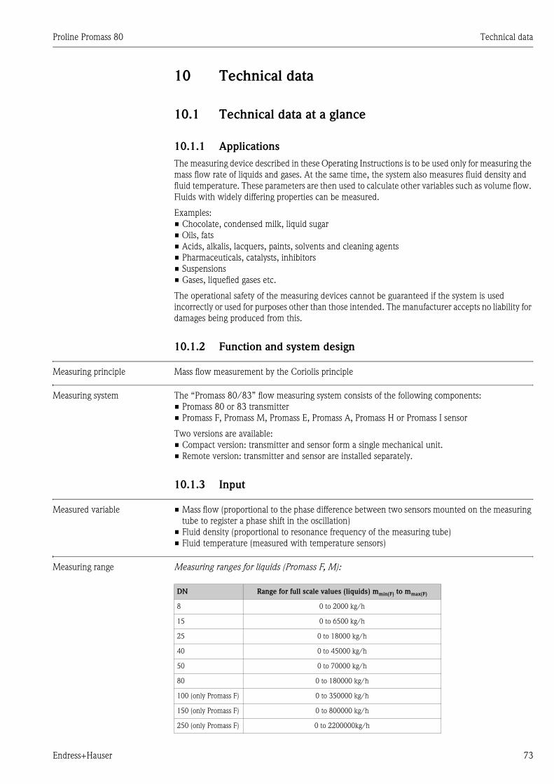
Proline Promass 80 Technical data
Endress+Hauser 73
10 Technical data
10.1 Technical data at a glance
10.1.1 Applications
The measuring device described in these Operating Instructions is to be used only for measuring the
mass flow rate of liquids and gases. At the same time, the system also measures fluid density and
fluid temperature. These parameters are then used to calculate other variables such as volume flow.
Fluids with widely differing properties can be measured.
Examples:
• Chocolate, condensed milk, liquid sugar
• Oils, fats
• Acids, alkalis, lacquers, paints, solvents and cleaning agents
• Pharmaceuticals, catalysts, inhibitors
• Suspensions
• Gases, liquefied gases etc.
The operational safety of the measuring devices cannot be guaranteed if the system is used
incorrectly or used for purposes other than those intended. The manufacturer accepts no liability for
damages being produced from this.
10.1.2 Function and system design
Measuring principle Mass flow measurement by the Coriolis principle
Measuring system The “Promass 80/83” flow measuring system consists of the following components:
• Promass 80 or 83 transmitter
• Promass F, Promass M, Promass E, Promass A, Promass H or Promass I sensor
Two versions are available:
• Compact version: transmitter and sensor form a single mechanical unit.
• Remote version: transmitter and sensor are installed separately.
10.1.3 Input
Measured variable • Mass flow (proportional to the phase difference between two sensors mounted on the measuring
tube to register a phase shift in the oscillation)
• Fluid density (proportional to resonance frequency of the measuring tube)
• Fluid temperature (measured with temperature sensors)
Measuring range Measuring ranges for liquids (Promass F, M):
DN Range for full scale values (liquids) mmin(F) to mmax(F)
8 0 to 2000 kg/h
15 0 to 6500 kg/h
25 0 to 18000 kg/h
40 0 to 45000 kg/h
50 0 to 70000 kg/h
80 0 to 180000 kg/h
100 (only Promass F) 0 to 350000 kg/h
150 (only Promass F) 0 to 800000 kg/h
250 (only Promass F) 0 to 2200000kg/h
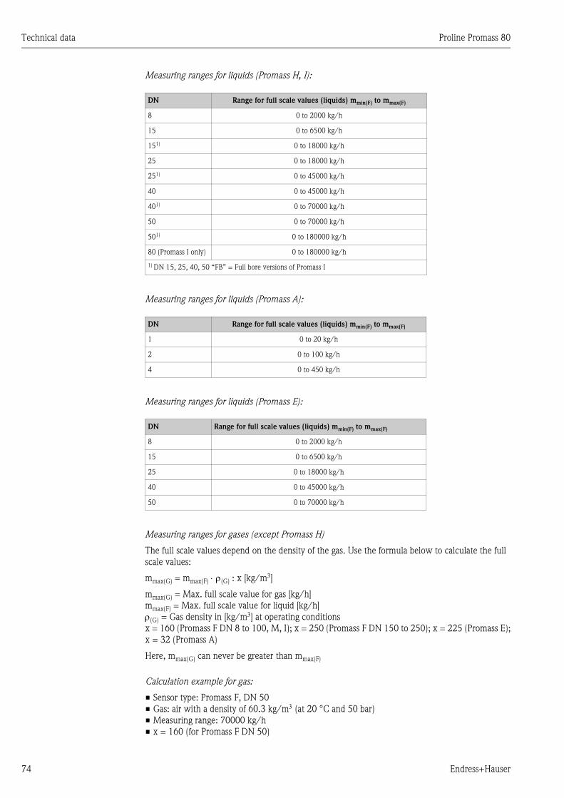
Technical data Proline Promass 80
74 Endress+Hauser
Measuring ranges for liquids (Promass H, I):
Measuring ranges for liquids (Promass A):
Measuring ranges for liquids (Promass E):
Measuring ranges for gases (except Promass H)
The full scale values depend on the density of the gas. Use the formula below to calculate the full
scale values:
mmax(G) = mmax(F) ⋅ ρ(G) : x [kg/m3]
mmax(G) = Max. full scale value for gas [kg/h]
mmax(F) = Max. full scale value for liquid [kg/h]
ρ(G) = Gas density in [kg/m3] at operating conditions
x = 160 (Promass F DN 8 to 100, M, I); x = 250 (Promass F DN 150 to 250); x = 225 (Promass E);
x = 32 (Promass A)
Here, mmax(G) can never be greater than mmax(F)
Calculation example for gas:
• Sensor type: Promass F, DN 50
• Gas: air with a density of 60.3 kg/m3 (at 20 °C and 50 bar)
• Measuring range: 70000 kg/h
• x = 160 (for Promass F DN 50)
DN Range for full scale values (liquids) mmin(F) to mmax(F)
8 0 to 2000 kg/h
15 0 to 6500 kg/h
151) 0 to 18000 kg/h
25 0 to 18000 kg/h
251) 0 to 45000 kg/h
40 0 to 45000 kg/h
401) 0 to 70000 kg/h
50 0 to 70000 kg/h
501) 0 to 180000 kg/h
80 (Promass I only) 0 to 180000 kg/h
1) DN 15, 25, 40, 50 “FB” = Full bore versions of Promass I
DN Range for full scale values (liquids) mmin(F) to mmax(F)
1 0 to 20 kg/h
2 0 to 100 kg/h
4 0 to 450 kg/h
DN Range for full scale values (liquids) mmin(F) to mmax(F)
8 0 to 2000 kg/h
15 0 to 6500 kg/h
25 0 to 18000 kg/h
40 0 to 45000 kg/h
50 0 to 70000 kg/h
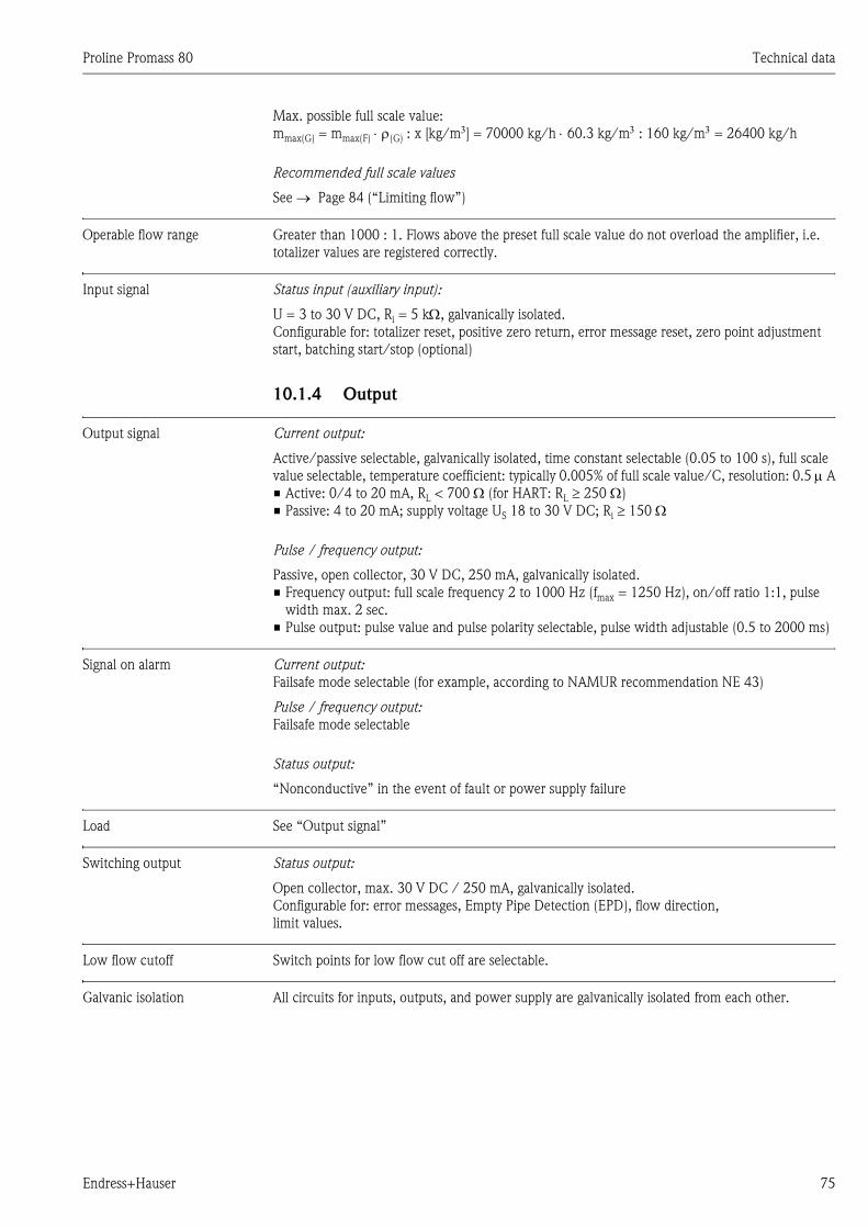
Proline Promass 80 Technical data
Endress+Hauser 75
Max. possible full scale value:
mmax(G) = mmax(F) ⋅ ρ(G) : x [kg/m3] = 70000 kg/h ⋅ 60.3 kg/m3 : 160 kg/m3 = 26400 kg/h
Recommended full scale values
See → Page 84 (“Limiting flow”)
Operable flow range Greater than 1000 : 1. Flows above the preset full scale value do not overload the amplifier, i.e.
totalizer values are registered correctly.
Input signal Status input (auxiliary input):
U = 3 to 30 V DC, Ri = 5 kΩ, galvanically isolated.
Configurable for: totalizer reset, positive zero return, error message reset, zero point adjustment
start, batching start/stop (optional)
10.1.4 Output
Output signal Current output:
Active/passive selectable, galvanically isolated, time constant selectable (0.05 to 100 s), full scale
value selectable, temperature coefficient: typically 0.005% of full scale value/C, resolution: 0.5 µ A
• Active: 0/4 to 20 mA, RL < 700 Ω (for HART: RL ≥ 250 Ω)
• Passive: 4 to 20 mA; supply voltage US 18 to 30 V DC; Ri ≥ 150 Ω
Pulse / frequency output:
Passive, open collector, 30 V DC, 250 mA, galvanically isolated.
• Frequency output: full scale frequency 2 to 1000 Hz (fmax = 1250 Hz), on/off ratio 1:1, pulse
width max. 2 sec.
• Pulse output: pulse value and pulse polarity selectable, pulse width adjustable (0.5 to 2000 ms)
Signal on alarm Current output:
Failsafe mode selectable (for example, according to NAMUR recommendation NE 43)
Pulse / frequency output:
Failsafe mode selectable
Status output:
“Nonconductive” in the event of fault or power supply failure
Load See “Output signal”
Switching output Status output:
Open collector, max. 30 V DC / 250 mA, galvanically isolated.
Configurable for: error messages, Empty Pipe Detection (EPD), flow direction,
limit values.
Low flow cutoff Switch points for low flow cut off are selectable.
Galvanic isolation All circuits for inputs, outputs, and power supply are galvanically isolated from each other.
Technical data Proline Promass 80
76 Endress+Hauser
10.1.5 Power supply
Electrical connections → Page 24
Supply voltage 85 to 260 V AC, 45 to 65 Hz
20 to 55 V AC, 45 to 65 Hz
16 to 62 V DC
Cable entry Power supply and signal cables (inputs/outputs):
• Cable entry M20 x 1.5 (8 to 12 mm)
• Threads for cable entries, 1/2" NPT, G 1/2"
Connecting cable for remote version:
• Cable entry M20 x 1.5 (8 to 12 mm)
• Threads for cable entries, 1/2" NPT, G 1/2"
Cable specifications (remote
version)
→ Page 25
Power consumption AC: <15 VA (including sensor)
DC: <15 W (including sensor)
Switch-on current:
• max. 13.5 A (< 50 ms) at 24 V DC
• max. 3 A (< 5 ms) at 260 V AC
Power supply failure Lasting min. 1 power cycle:
• EEPROM saves measuring system data if power supply fails.
• S-DATis an exchangeable data storage chip with sensor specific data: (nominal diameter, serial
number, calibration factor, zero point etc.).
Potential equalization No measures necessary.
10.1.6 Performance characteristics
Reference operating
conditions
Error limits following ISO/DIS 11631:
• 20 to 30 °C; 2 to 4 bar
• Calibration systems as per national norms
• Zero point calibrated under operating conditions
• Field density calibrated (or special density calibration)
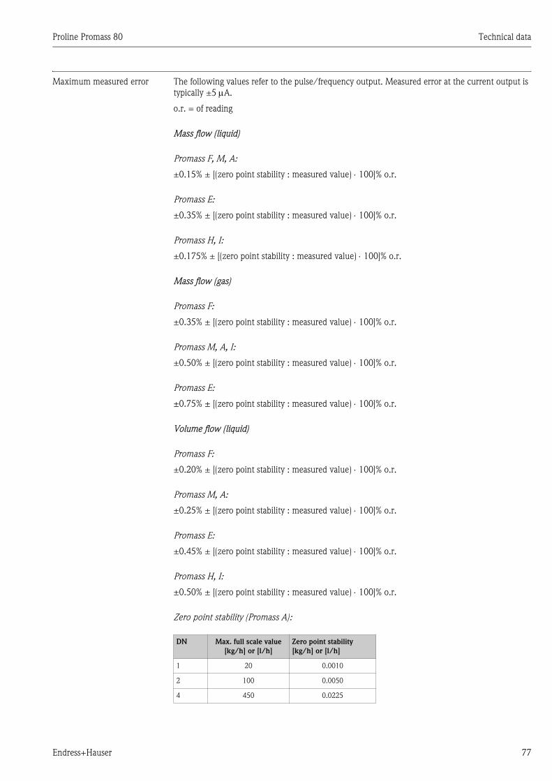
Proline Promass 80 Technical data
Endress+Hauser 77
Maximum measured error The following values refer to the pulse/frequency output. Measured error at the current output is
typically ±5 µA.
o.r. = of reading
Mass flow (liquid)
Promass F, M, A:
±0.15% ± [(zero point stability : measured value) ⋅ 100]% o.r.
Promass E:
±0.35% ± [(zero point stability : measured value) ⋅ 100]% o.r.
Promass H, I:
±0.175% ± [(zero point stability : measured value) ⋅ 100]% o.r.
Mass flow (gas)
Promass F:
±0.35% ± [(zero point stability : measured value) ⋅ 100]% o.r.
Promass M, A, I:
±0.50% ± [(zero point stability : measured value) ⋅ 100]% o.r.
Promass E:
±0.75% ± [(zero point stability : measured value) ⋅ 100]% o.r.
Volume flow (liquid)
Promass F:
±0.20% ± [(zero point stability : measured value) ⋅ 100]% o.r.
Promass M, A:
±0.25% ± [(zero point stability : measured value) ⋅ 100]% o.r.
Promass E:
±0.45% ± [(zero point stability : measured value) ⋅ 100]% o.r.
Promass H, I:
±0.50% ± [(zero point stability : measured value) ⋅ 100]% o.r.
Zero point stability (Promass A):
DN Max. full scale value
[kg/h] or [l/h]
Zero point stability
[kg/h] or [l/h]
1 20 0.0010
2 100 0.0050
4 450 0.0225
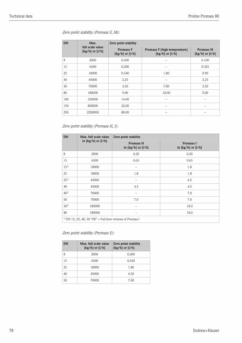
Technical data Proline Promass 80
78 Endress+Hauser
Zero point stability (Promass F, M):
Zero point stability (Promass H, I):
Zero point stability (Promass E):
DN Max.
full scale value
[kg/h] or [l/h]
Zero point stability
Promass F
[kg/h] or [l/h]
Promass F (high-temperature)
[kg/h] or [l/h]
Promass M
[kg/h] or [l/h]
8 2000 0.030 − 0.100
15 6500 0.200 − 0.325
25 18000 0.540 1.80 0.90
40 45000 2.25 − 2.25
50 70000 3.50 7.00 3.50
80 180000 9.00 18.00 9.00
100 350000 14.00 − −
150 800000 32.00 − −
250 2200000 88.00 − −
DN Max. full scale value
in [kg/h] or [l/h]
Zero point stability
Promass H
in [kg/h] or [l/h]
Promass I
in [kg/h] or [l/h]
8 2000 0.20 0.20
15 6500 0.65 0.65
151) 18000 − 1.8
25 18000 1.8 1.8
251) 45000 − 4.5
40 45000 4.5 4.5
401) 70000 − 7.0
50 70000 7.0 7.0
501) 180000 – 18.0
80 180000 – 18.0
1) DN 15, 25, 40, 50 “FB” = Full bore versions of Promass I
DN Max. full scale value
[kg/h] or [l/h]
Zero point stability
[kg/h] or [l/h]
8 2000 0.200
15 6500 0.650
25 18000 1.80
40 45000 4.50
50 70000 7.00
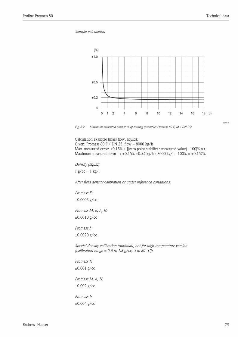
Proline Promass 80 Technical data
Endress+Hauser 79
Sample calculation
a0004649
Fig. 35: Maximum measured error in % of reading (example: Promass 80 F, M / DN 25)
Calculation example (mass flow, liquid):
Given: Promass 80 F / DN 25, flow = 8000 kg/h
Max. measured error: ±0.15% ± [(zero point stability : measured value) ⋅ 100]% o.r.
Maximum measured error → ±0.15% ±0.54 kg/h : 8000 kg/h ⋅ 100% = ±0.157%
Density (liquid)
1 g/cc = 1 kg/l
After field density calibration or under reference conditions:
Promass F:
±0.0005 g/cc
Promass M, E, A, H:
±0.0010 g/cc
Promass I:
±0.0020 g/cc
Special density calibration (optional), not for high-temperature version
(calibration range = 0.8 to 1.8 g/cc, 5 to 80 °C):
Promass F:
±0.001 g/cc
Promass M, A, H:
±0.002 g/cc
Promass I:
±0.004 g/cc
0
±0.5
±0.2
±1.0
[%]
0 1 2 4 6 8 10 12 14 16 18 t/h
Technical data Proline Promass 80
80 Endress+Hauser
Standard calibration:
Promass F:
±0.01 g/cc
Promass M, E, A, H, I:
±0.02 g/cc
Temperature
±0.5 °C ±0.005 ⋅ T (T = fluid temperature in °C)
Repeatability Mass flow (liquid):
Promass F, M, A, H, I:
±0.05% ± [1/2 ⋅ (zero point stability : measured value) ⋅ 100]% o.r.
Promass E:
±0.20% ± [1/2 ⋅ (zero point stability : measured value) ⋅ 100]% o.r.
Mass flow (gas):
Promass F, M, A, I:
±0.25% ± [1/2 ⋅ (zero point stability : measured value) ⋅ 100]% o.r.
Promass E:
±0.35% ± [1/2 ⋅ (zero point stability : measured value) ⋅ 100]% o.r.
Volume flow (liquid):
Promass F:
±0.05% ± [1/2 ⋅ (zero point stability : measured value) ⋅ 100]% o.r.
Promass M, A:
±0.10% ± [1/2 ⋅ (zero point stability : measured value) ⋅ 100]% o.r.
Promass E:
±0.25% ± [1/2 ⋅ (zero point stability : measured value) ⋅ 100]% o.r.
Promass H, I:
±0.20% ± [1/2 ⋅ (zero point stability : measured value) ⋅ 100]% o.r.
o.r. = of reading
Zero point stability: see “Max. measured error”→ Page 77
Calculation example (mass flow, liquid):
Given: Promass 80 F / DN 25, flow = 8000 kg/h
Repeatability: ±0.05% ± [1/2 ⋅ (zero point stability : measured value) ⋅ 100]% o.r.
Repeatability → ±0.05% ±1/2 ⋅ 0.54 kg/h : 8000 kg/h ⋅ 100% = ±0.053%
Proline Promass 80 Technical data
Endress+Hauser 81
Density measurement (liquid)
1 g/cc = 1 kg/l
Promass F:
±0.00025 g/cc
Promass M, H, E, A:
±0.0005 g/cc
Promass I:
±0.001 g/cc
Temperature measurement
±0.25 °C ±0.0025 ⋅ T (T = fluid temperature in °C)
Influence of medium
temperature
When there is a difference between the temperature for zero point adjustment and the
process temperature, the typical measured error of the Promass sensor is ±0.0002% of
the full scale value / °C. The typical measured error of the Promass E sensor is ±0.0003% of
the full scale value / °C.
Influence of medium pressure The table below shows the effect on accuracy of mass flow due to a difference between calibration
pressure and process pressure.
Promass F, M:
Promass E:
With nominal diameters DN 8 to 40, the effect on accuracy of mass flow due to a difference between
calibration pressure and process pressure can be neglected.
For DN 50 the effect is –0.009% o.r. / bar (o.r. = of reading).
Promass A:
A difference between calibration pressure and process pressure has no effect on measuring accuracy.
DN Promass F
Promass F, high-temperature
[% o.r./bar]
Promass M
[% o.r./bar]
Promass M / (high pressure)
[% o.r./bar]
8 No influence 0.009 0.006
15 No influence 0.008 0.005
25 No influence 0.009 0.003
40 −0.003 0.005 −
50 −0.008 No influence −
80 −0.009 No influence −
100 −0.012 − −
150 −0.009 − −
250 −0.009 − −
o.r. = of reading
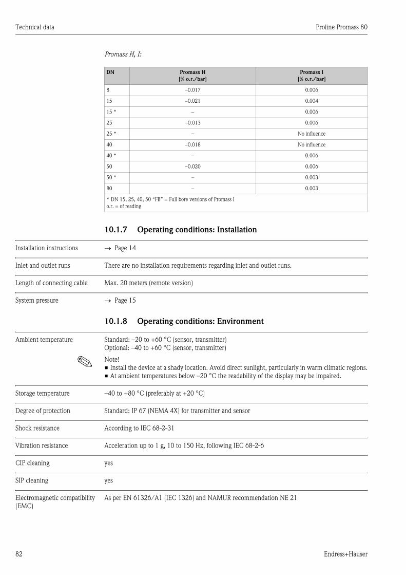
Technical data Proline Promass 80
82 Endress+Hauser
Promass H, I:
10.1.7 Operating conditions: Installation
Installation instructions → Page 14
Inlet and outlet runs There are no installation requirements regarding inlet and outlet runs.
Length of connecting cable Max. 20 meters (remote version)
System pressure → Page 15
10.1.8 Operating conditions: Environment
Ambient temperature Standard: –20 to +60 °C (sensor, transmitter)
Optional: –40 to +60 °C (sensor, transmitter)
! Note!
• Install the device at a shady location. Avoid direct sunlight, particularly in warm climatic regions.
• At ambient temperatures below –20 °C the readability of the display may be impaired.
Storage temperature –40 to +80 °C (preferably at +20 °C)
Degree of protection Standard: IP 67 (NEMA 4X) for transmitter and sensor
Shock resistance According to IEC 68-2-31
Vibration resistance Acceleration up to 1 g, 10 to 150 Hz, following IEC 68-2-6
CIP cleaning yes
SIP cleaning yes
Electromagnetic compatibility
(EMC)
As per EN 61326/A1 (IEC 1326) and NAMUR recommendation NE 21
DN Promass H
[% o.r./bar]
Promass I
[% o.r./bar]
8 −0.017 0.006
15 −0.021 0.004
15 * − 0.006
25 −0.013 0.006
25 * – No influence
40 −0.018 No influence
40 * – 0.006
50 −0.020 0.006
50 * – 0.003
80 – 0.003
* DN 15, 25, 40, 50 “FB” = Full bore versions of Promass I
o.r. = of reading
Proline Promass 80 Technical data
Endress+Hauser 83
10.1.9 Operating conditions: Process
Medium temperature range Sensor:
Promass F, A, H:
–50 to +200 °C
Promass F (high-temperature version):
–50 to +350 °C
Promass M, I:
–50 to +150 °C
Promass E:
–40 to +125 °C
Seals:
Promass F, E, H, I:
No internal seals
Promass M:
Viton –15 to +200 °C; EPDM –40 to +160 °C; silicon –60 to +200 °C; Kalrez –20 to +275 °C;
FEP sheathed (not for gas applications): –60 to +200 °C
Promass A
(only for mounting sets with threaded connections)
Viton –15 to 200 °C; EPDM –40 to +160 °C; silicon –60 to +200 °C; Kalrez –20 to +275 °C
Limiting medium pressure
range (rated pressure)
The material load curves (pressure–temperature diagrams) for the process connections are included
in the separate “Technical information” documentation for the respective measuring device, which
you can download in PDF format at www.endress.com.
A list of the available “Technical information” documents can be found in the “Supplementary
documentation” section → Page 96
Pressure ranges of secondary containment:
Promass F:
DN 8 to 50: 40 bar or 600 psi; DN 80: 25 bar or 375 psi;
DN 100 to 150: 16 bar or 250 psi; DN 250: 10 bar or 150 psi
Promass M:
100 bar or 1500 psi
Promass E:
No secondary containment
Promass A:
25 bar or 375 psi
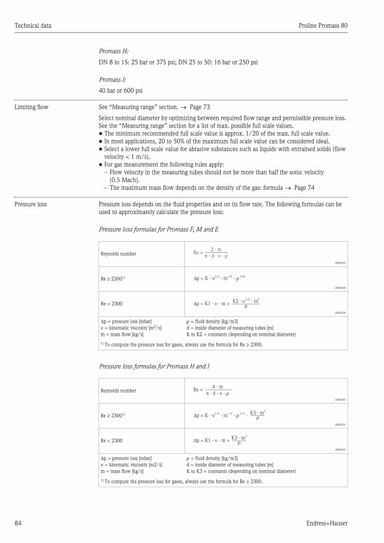
Technical data Proline Promass 80
84 Endress+Hauser
Promass H:
DN 8 to 15: 25 bar or 375 psi; DN 25 to 50: 16 bar or 250 psi
Promass I:
40 bar or 600 psi
Limiting flow See “Measuring range” section. → Page 73
Select nominal diameter by optimizing between required flow range and permissible pressure loss.
See the “Measuring range” section for a list of max. possible full scale values.
• The minimum recommended full scale value is approx. 1/20 of the max. full scale value.
• In most applications, 20 to 50% of the maximum full scale value can be considered ideal.
• Select a lower full scale value for abrasive substances such as liquids with entrained solids (flow
velocity < 1 m/s).
• For gas measurement the following rules apply:
– Flow velocity in the measuring tubes should not be more than half the sonic velocity
(0.5 Mach).
– The maximum mass flow depends on the density of the gas: formula → Page 74
Pressure loss Pressure loss depends on the fluid properties and on its flow rate. The following formulas can be
used to approximately calculate the pressure loss:
Pressure loss formulas for Promass F, M and E
Pressure loss formulas for Promass H and I
Reynolds number
a0004623
Re ≥ 23001)
a0004626
Re < 2300
a0004628
∆p = pressure loss [mbar]
ν = kinematic viscosity [m2/s]
m = mass flow [kg/s]
ρ = fluid density [kg/m3]
d = inside diameter of measuring tubes [m]
K to K2 = constants (depending on nominal diameter)
1) To compute the pressure loss for gases, always use the formula for Re ≥ 2300.
Reynolds number
a0003381
Re ≥ 23001)
a0004631
Re < 2300
a0004633
∆p = pressure loss [mbar]
ν = kinematic viscosity [m2/s]
m = mass flow [kg/s]
ρ = fluid density [kg/m3]
d = inside diameter of measuring tubes [m]
K to K3 = constants (depending on nominal diameter)
1) To compute the pressure loss for gases, always use the formula for Re ≥ 2300.
Re =2 · m
· d · ·
p = K · · m ·0.25 1.85 –0.86
p = K1 · · m +K2 · · m
0.25 2
Re = · d · ·
4 · m
p = K · · m ·0.25 1.75 –0.75
·K3 · m
2
p = K1 · · m +K3 · m
2
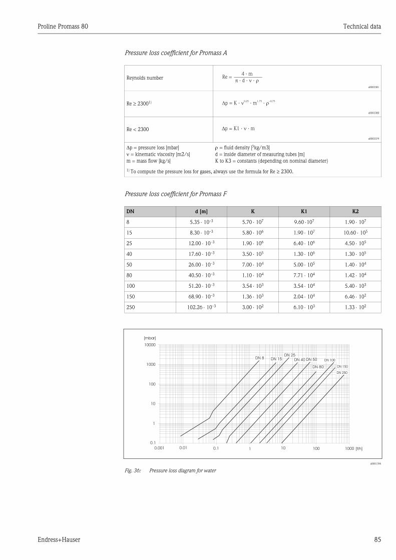
Proline Promass 80 Technical data
Endress+Hauser 85
Pressure loss coefficient for Promass A
Pressure loss coefficient for Promass F
a0001396
Fig. 36: Pressure loss diagram for water
Reynolds number
a0003381
Re ≥ 23001)
a0003380
Re < 2300
a0003379
∆p = pressure loss [mbar]
ν = kinematic viscosity [m2/s]
m = mass flow [kg/s]
ρ = fluid density [3kg/m3]
d = inside diameter of measuring tubes [m]
K to K3 = constants (depending on nominal diameter)
1) To compute the pressure loss for gases, always use the formula for Re ≥ 2300.
DN d [m] K K1 K2
8 5.35 ⋅ 10–3 5.70 ⋅ 107 9.60 ⋅107 1.90 ⋅ 107
15 8.30 ⋅ 10–3 5.80 ⋅ 106 1.90 ⋅ 107 10.60 ⋅ 105
25 12.00 ⋅ 10–3 1.90 ⋅ 106 6.40 ⋅ 106 4.50 ⋅ 105
40 17.60 ⋅ 10–3 3.50 ⋅ 105 1.30 ⋅ 106 1.30 ⋅ 105
50 26.00 ⋅ 10–3 7.00 ⋅ 104 5.00 ⋅ 105 1.40 ⋅ 104
80 40.50 ⋅ 10–3 1.10 ⋅ 104 7.71 ⋅ 104 1.42 ⋅ 104
100 51.20 ⋅ 10–3 3.54 ⋅ 103 3.54 ⋅ 104 5.40 ⋅ 103
150 68.90 ⋅ 10–3 1.36 ⋅ 103 2.04 ⋅ 104 6.46 ⋅ 102
250 102.26 ⋅ 10–3 3.00 ⋅ 102 6.10 ⋅ 103 1.33 ⋅ 102
Re = · d · ·
4 · m
p = K ·0.25
· m ·1.75 –0.75
p = K1 · · m
DN 50DN 40DN 25
DN 8
10000
1000
100
10
1
0.1
0.001 0.01 0.1 1 10 100 1000
DN 15
DN 80
DN 100
[mbar]
[t/h]
DN 150
DN 250
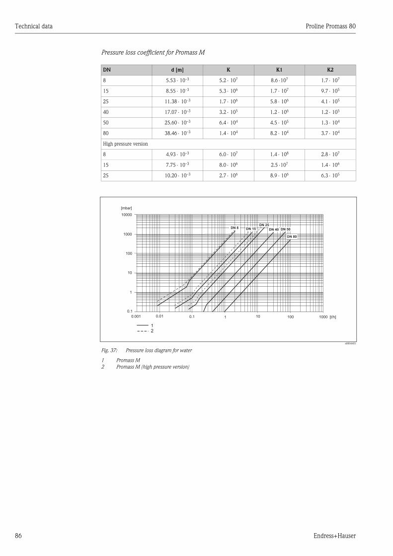
Technical data Proline Promass 80
86 Endress+Hauser
Pressure loss coefficient for Promass M
a0004605
Fig. 37: Pressure loss diagram for water
1 Promass M
2 Promass M (high pressure version)
DN d [m] K K1 K2
8 5.53 ⋅ 10–3 5.2 ⋅ 107 8.6 ⋅107 1.7 ⋅ 107
15 8.55 ⋅ 10–3 5.3 ⋅ 106 1.7 ⋅ 107 9.7 ⋅ 105
25 11.38 ⋅ 10–3 1.7 ⋅ 106 5.8 ⋅ 106 4.1 ⋅ 105
40 17.07 ⋅ 10–3 3.2 ⋅ 105 1.2 ⋅ 106 1.2 ⋅ 105
50 25.60 ⋅ 10–3 6.4 ⋅ 104 4.5 ⋅ 105 1.3 ⋅ 104
80 38.46 ⋅ 10–3 1.4 ⋅ 104 8.2 ⋅ 104 3.7 ⋅ 104
High pressure version
8 4.93 ⋅ 10–3 6.0 ⋅ 107 1.4 ⋅ 108 2.8 ⋅ 107
15 7.75 ⋅ 10–3 8.0 ⋅ 106 2.5 ⋅107 1.4 ⋅ 106
25 10.20 ⋅ 10–3 2.7 ⋅ 106 8.9 ⋅ 106 6.3 ⋅ 105
DN 50DN 40
DN 25DN 8
10000
1000
100
10
1
0.1
0.001 0.01 0.1 1 10 100 1000
DN 15
DN 80
[mbar]
[t/h]
12
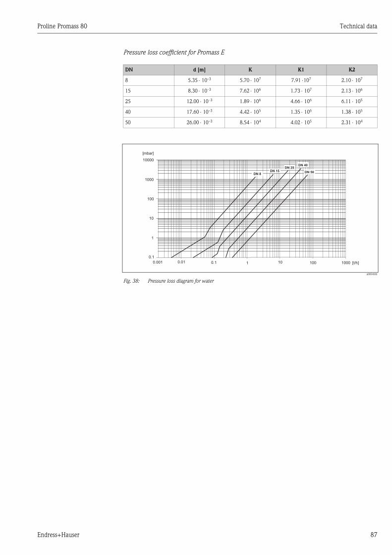
Proline Promass 80 Technical data
Endress+Hauser 87
Pressure loss coefficient for Promass E
a0004606
Fig. 38: Pressure loss diagram for water
DN d [m] K K1 K2
8 5.35 ⋅ 10–3 5.70 ⋅ 107 7.91 ⋅107 2.10 ⋅ 107
15 8.30 ⋅ 10–3 7.62 ⋅ 106 1.73 ⋅ 107 2.13 ⋅ 106
25 12.00 ⋅ 10–3 1.89 ⋅ 106 4.66 ⋅ 106 6.11 ⋅ 105
40 17.60 ⋅ 10–3 4.42 ⋅ 105 1.35 ⋅ 106 1.38 ⋅ 105
50 26.00 ⋅ 10–3 8.54 ⋅ 104 4.02 ⋅ 105 2.31 ⋅ 104
DN 50
DN 40DN 25
DN 8
10000
1000
100
10
1
0.1
0.001 0.01 0.1 1 10 100 1000
DN 15
[mbar]
[t/h]
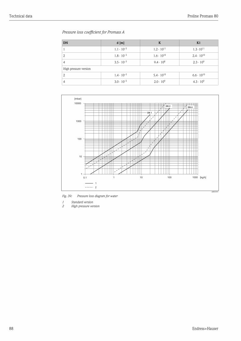
Technical data Proline Promass 80
88 Endress+Hauser
Pressure loss coefficient for Promass A
a0003595
Fig. 39: Pressure loss diagram for water
1 Standard version
2 High pressure version
DN d [m] K K1
1 1.1 ⋅ 10–3 1.2 ⋅ 1011 1.3 ⋅1011
2 1.8 ⋅ 10–3 1.6 ⋅ 1010 2.4 ⋅ 1010
4 3.5 ⋅ 10–3 9.4 ⋅ 108 2.3 ⋅ 109
High pressure version
2 1.4 ⋅ 10–3 5.4 ⋅ 1010 6.6 ⋅ 1010
4 3.0 ⋅ 10–3 2.0 ⋅ 109 4.3 ⋅ 109
[mbar]
[kg/h]
1
DN 2
10000
1000
100
10
1
0.1 1 10 100 1000
DN 4
DN 1
2
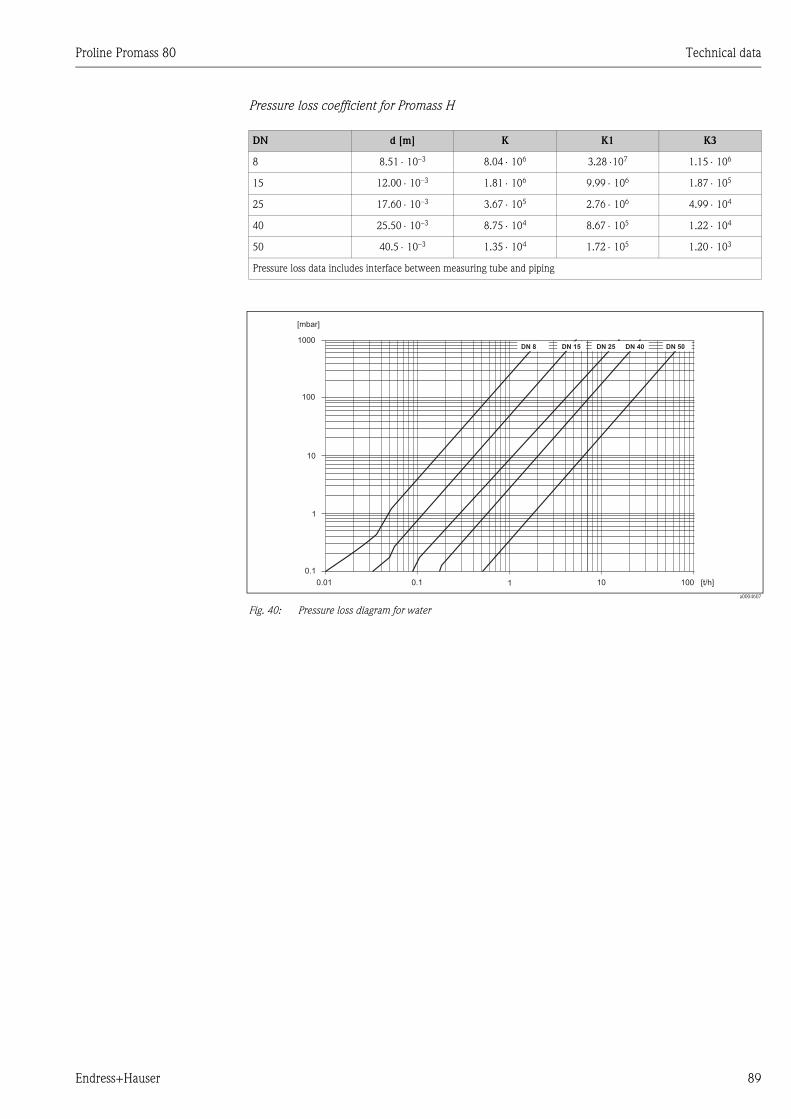
Proline Promass 80 Technical data
Endress+Hauser 89
Pressure loss coefficient for Promass H
a0004607
Fig. 40: Pressure loss diagram for water
DN d [m] K K1 K3
8 8.51 ⋅ 10–3 8.04 ⋅ 106 3.28 ⋅107 1.15 ⋅ 106
15 12.00 ⋅ 10–3 1.81 ⋅ 106 9.99 ⋅ 106 1.87 ⋅ 105
25 17.60 ⋅ 10–3 3.67 ⋅ 105 2.76 ⋅ 106 4.99 ⋅ 104
40 25.50 ⋅ 10–3 8.75 ⋅ 104 8.67 ⋅ 105 1.22 ⋅ 104
50 40.5 ⋅ 10–3 1.35 ⋅ 104 1.72 ⋅ 105 1.20 ⋅ 103
Pressure loss data includes interface between measuring tube and piping
1000
100
10
1
0.1
0.01 0.1 1 10 100
[mbar]
[t/h]
DN 40 DN 50DN 25DN 15DN 8
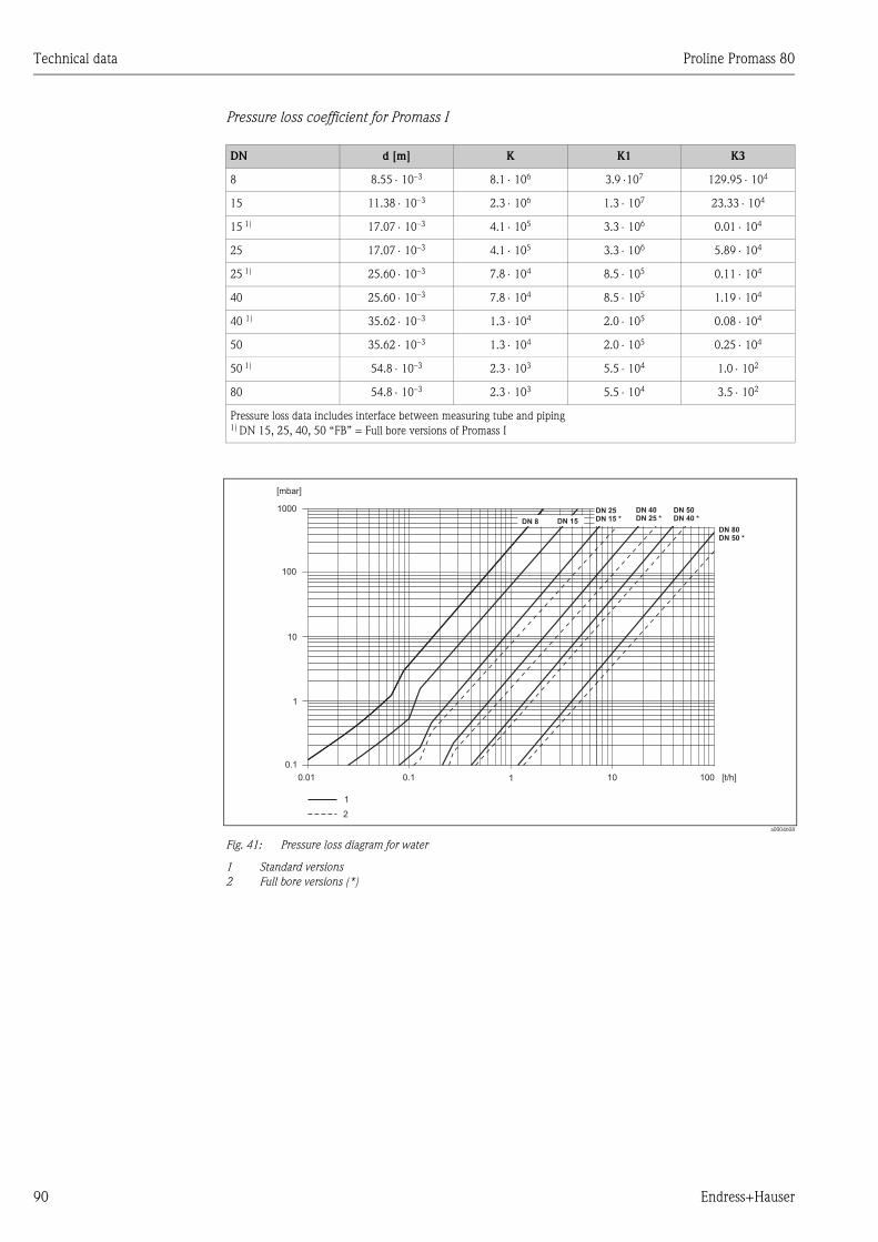
Technical data Proline Promass 80
90 Endress+Hauser
Pressure loss coefficient for Promass I
a0004608
Fig. 41: Pressure loss diagram for water
1 Standard versions
2 Full bore versions (*)
DN d [m] K K1 K3
8 8.55 ⋅ 10–3 8.1 ⋅ 106 3.9 ⋅107 129.95 ⋅ 104
15 11.38 ⋅ 10–3 2.3 ⋅ 106 1.3 ⋅ 107 23.33 ⋅ 104
15 1) 17.07 ⋅ 10–3 4.1 ⋅ 105 3.3 ⋅ 106 0.01 ⋅ 104
25 17.07 ⋅ 10–3 4.1 ⋅ 105 3.3 ⋅ 106 5.89 ⋅ 104
25 1) 25.60 ⋅ 10–3 7.8 ⋅ 104 8.5 ⋅ 105 0.11 ⋅ 104
40 25.60 ⋅ 10–3 7.8 ⋅ 104 8.5 ⋅ 105 1.19 ⋅ 104
40 1) 35.62 ⋅ 10–3 1.3 ⋅ 104 2.0 ⋅ 105 0.08 ⋅ 104
50 35.62 ⋅ 10–3 1.3 ⋅ 104 2.0 ⋅ 105 0.25 ⋅ 104
50 1) 54.8 ⋅ 10–3 2.3 ⋅ 103 5.5 ⋅ 104 1.0 ⋅ 102
80 54.8 ⋅ 10–3 2.3 ⋅ 103 5.5 ⋅ 104 3.5 ⋅ 102
Pressure loss data includes interface between measuring tube and piping1) DN 15, 25, 40, 50 “FB” = Full bore versions of Promass I
1000
100
10
1
0.1
0.01 0.1 1 10 100
DN 40
DN 25 *
DN 50
DN 40 *
DN 25
DN 15 *DN 15
[mbar]
[t/h]
1
DN 8
DN 80
DN 50 *
2
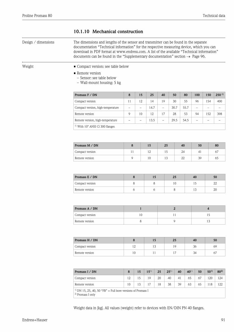
Proline Promass 80 Technical data
Endress+Hauser 91
10.1.10 Mechanical construction
Design / dimensions The dimensions and lengths of the sensor and transmitter can be found in the separate
documentation “Technical information” for the respective measuring device, which you can
download in PDF format at www.endress.com. A list of the available “Technical information”
documents can be found in the “Supplementary documentation” section → Page 96.
Weight • Compact version: see table below
• Remote version
– Sensor: see table below
– Wall-mount housing: 5 kg
Weight data in [kg]. All values (weight) refer to devices with EN/DIN PN 40 flanges.
Promass F / DN 8 15 25 40 50 80 100 150 250 1)
Compact version 11 12 14 19 30 55 96 154 400
Compact version, high-temperature − − 14.7 − 30.7 55.7 − − −
Remote version 9 10 12 17 28 53 94 152 398
Remote version, high-temperature − − 13.5 − 29.5 54.5 − − −
1) With 10" ANSI Cl 300 flanges
Promass M / DN 8 15 25 40 50 80
Compact version 11 12 15 24 41 67
Remote version 9 10 13 22 39 65
Promass E / DN 8 15 25 40 50
Compact version 8 8 10 15 22
Remote version 6 6 8 13 20
Promass A / DN 1 2 4
Compact version 10 11 15
Remote version 8 9 13
Promass H / DN 8 15 25 40 50
Compact version 12 13 19 36 69
Remote version 10 11 17 34 67
Promass I / DN 8 15 151) 25 251) 40 401) 50 501) 802)
Compact version 12 15 19 20 40 41 65 67 120 124
Remote version 10 13 17 18 38 39 63 65 118 122
1) DN 15, 25, 40, 50 “FB” = Full bore versions of Promass I2) Promass I only
Technical data Proline Promass 80
92 Endress+Hauser
Material Transmitter housing
• Compact housing: stainless steel 1.4301/304
• Compact housing: powder coated die-cast aluminum
• Wall-mount housing: powder coated die-cast aluminum
• Remote field housing: powder-coated die-cast aluminum
Sensor housing / containment:
Promass F:
Acid- and alkali-resistant outer surface
DN 8 to 50: stainless steel 1.4301/304
DN 80 to 250: stainless steel 1.4301/304 and 1.4308/304L
Promass M:
Acid- and alkali-resistant outer surface
DN 8 to 50: steel, chemically nickel-plated
DN 80: stainless steel
Promass E, A, H, I:
• Acid- and alkali-resistant outer surface
• Stainless steel 1.4301/304
Connection housing, sensor (remote version):
• Stainless steel 1.4301/304 (standard)
• powder coated die-cast aluminum (high-temperature version and version for heating)
Process connections
Promass F:
• Flanges EN 1092-1 (DIN 2501) / ANSI B16.5 / JIS B2238 → stainless steel 1.4404/316L
• Flanges EN 1092-1 (DIN 2501) / ANSI B16.5 / JIS B2238 → Alloy C-22 2.4602/N 06022
• Flange DIN 11864-2 Form A (flat flange) → stainless steel 1.4404/316L
• Hygienic coupling DIN 11851 / SMS 1145 → stainless steel 1.4404/316L
• Couplings ISO 2853 / DIN 11864-1 → stainless steel 1.4404/316L
• Tri–Clamp (OD–tubes)→ stainless steel 1.4404/316L
• VCO connection → Stainless steel 1.4404/316L
Promass F (high-temperature version):
• Flanges EN 1092-1 (DIN 2501) / ANSI B16.5 / JIS B2238 → stainless steel 1.4404/316L
• Flanges EN 1092-1 (DIN 2501) / ANSI B16.5 / JIS B2238 → Alloy C-22 2.4602 (N 06022)
Promass E:
• Flanges EN 1092-1 (DIN 2501) / ANSI B16.5 / JIS B2238 → stainless steel 1.4404/316L
• Flange DIN 11864-2 Form A (flat flange) → stainless steel 1.4404/316L
• VCO connection → Stainless steel 1.4404/316L
• Hygienic coupling DIN 11851 / SMS 1145 → stainless steel 1.4404/316L
• Couplings ISO 2853 / DIN 11864-1 → stainless steel 1.4404/316L
• Tri–Clamp (OD–tubes)→ stainless steel 1.4404/316L
Proline Promass 80 Technical data
Endress+Hauser 93
Promass M:
• Flanges EN 1092-1 (DIN 2501) / ANSI B16.5 / JIS B2238 → stainless steel 1.4404/316L,
titanium grade 2
• Flange DIN 11864-2 Form A (flat range) → stainless steel 1.4404/316L
• PVDF connection to DIN / ANSI / JIS
• Hygienic coupling DIN 11851 / SMS 1145 → stainless steel 1.4404/316L
• Coulpings ISO 2853 / DIN 11864-1 → stainless steel 1.4404/316L
• Tri–Clamp (OD–tubes)→ stainless steel 1.4404/316L
Promass M (high pressure version):
• Connector → stainless steel 1.4404/316L
• Couplings → stainless steel 1.4401/316
Promass A:
• Mounting set for flanges EN 1092-1 (DIN 2501) / ANSI B16.5 / JIS B2238 → stainless steel
1.4539/904L, Alloy C-22 2.4602/N 06022.
Loose flanges → stainless steel 1.4404/316L
• VCO Coupling → stainless steel 1.4539/904L, Alloy C-22 2.4602/N 06022
• Tri–Clamp (OD–tubes) (1/2") → stainless steel 1.4539/904L
• Mounting set for SWAGELOK (1/4", 1/8") → stainless steel 1.4401/316
• Mounting set for NPT-F (1/4") → stainless steel 1.4539/904L1.4539/904L,
Alloy C-22 2.4602/N 06022
Promass H:
• Flanges EN 1092–-1 (DIN 2501) / ANSI B16.5 / JIS B2238 → stainless steel 1.4301/304, parts
in contact with medium: zirconium 702
Promass I:
• Flanges EN 1092-1 (DIN 2501) / ANSI B16.5 / JIS B2238 → stainless steel 1.4301/304
• Flange DIN 11864-2 Form A (flat range) → titanium grade 2
• Hygienic coupling DIN 11851 / SMS 1145 → titanium grade 2
• Couplings ISO 2853 / DIN 11864-1 → titanium grade 2
• Tri–Clamp (OD–tubes) → titanium grade 2
Measuring tube(s):
Promass F:
• DN 8 to 100: stainless steel 1.4539/904L
• DN 150: stainless steel 1.4404/316L
• DN 250: stainless steel 1.4404/316L; manifold: CF3M
• DN 8 to 150: Alloy C-22 2.4602/N 06022
Promass F (high-temperature version):
• DN 25, 50, 80: Alloy C-22 2.4602/N 06022
Promass M:
• DN 8 to 50: titanium grade 9
• DN 80: titanium grade 2
Promass M (high pressure version):
• Titanium grade 9
Technical data Proline Promass 80
94 Endress+Hauser
Promass E:
• Stainless steel 1.4539/904L
Promass A:
• Stainless steel 1.4539/904L, Alloy C-22 2.4602/N 06022
Promass H:
• Zirconium 702/R 60702
Promass I:
• Titanium grade 9
• Titanium grade 2 (flange disks)
Seals:
Promass F, E, H, I:
Welded process connections without internal seals
Promass M:
Viton, EPDM, silicon, Kalrez, FEP sheathing (not for gas applications)
Promass A:
Viton, EPDM, silicon, Kalrez
Material load diagram The material load curves (pressure–temperature diagrams) for the process connections are included
in the separate “Technical information” documentation for the respective measuring device, which
you can download in PDF format at www.endress.com.
A list of the available “Technical information” documents can be found in the “Supplementary
documentation” section → Page 96
Process connections → Page 92 ff.
10.1.11 Human interface
Display elements • Liquid crystal display: illuminated, two lines with 16 characters per line
• Selectable display of different measured values and status variables
• At ambient temperatures below –20 °C the readability of the display may be impaired.
Operating elements • Local operation with push buttons (–, +, E)
• Quick Setup menus for straightforward commissioning
Language groups Language groups available for operation in different countries:
• Western Europe and America (WEA):
English, German, Spanish, Italian, French, Dutch and Portuguese
• Eastern Europe and Scandinavia (EES):
English, Russian, Polish, Norwegian, Finnish, Swedish and Czech
• South and east Asia (SEA):
English, Japanese, Indonesian
! Note!
You can change the language group via the operating program “ToF Tool - Fieldtool Package.”
Proline Promass 80 Technical data
Endress+Hauser 95
Remote operation Operation by means of HART protocol
10.1.12 Certificates and approvals
CE mark The measuring system is in conformity with the statutory requirements of the EC Directives.
Endress+Hauser confirms successful testing of the device by affixing to it the CE mark.
C-Tick symbol The measuring system complies with the EMC requirements of the “Australian Communications
Authority (ACA)”.
Ex approval Information about currently available Ex versions (ATEX, FM, CSA etc.) can be supplied by your
Endress+Hauser Sales Center on request. All information relevant to explosion protection is
available in separate Ex documents that you can order as necessary.
Sanitary compatibility • 3A authorization (all measuring systems, except Promass H)
• EHEDG-tested (Promass A and Promass I only)
Pressure device approval Flowmeters with a nominal diameter smaller or equal DN 25 are covered by Art. 3(3) of the
European directive 97/23/EC (Pressure Equipment Directive) and are designed according to sound
engineer practice. For larger nominal diameters, optional approvals according to Cat. II/III are
available when required (depends on fluid and process pressure).
Functional safety SIL -2:
In accordance with IEC 61508/IEC 61511-1 (FDIS)
Other standards and
guidelines
• EN 60529
Degrees of protection by housing (IP code)
• EN 61010
Safety requirements for electrical equipment for measurement, control and laboratory use
• EN 61326/A1 (IEC 1326)
“Emission in accordance with requirements for Class A”.
Electromagnetic compatibility (EMC requirements)
• NAMUR NE 21
Electromagnetic compatibility (EMC) of industrial process and laboratory control equipment.
• NAMUR NE 43
Standardization of the signal level for the breakdown information of digital transmitters with
analog output signal.
• NAMUR NE 53
Software of field devices and signal-processing devices with digital electronics

Technical data Proline Promass 80
96 Endress+Hauser
10.1.13 Ordering information
The Endress +Hauser service organization can provide detailed ordering information and
information on the order codes on request.
10.1.14 Accessories
Various accessories, which can be ordered separately from Endress+Hauser, are available for the
transmitter and the sensor. → Page 56
! Note!
The Endress+Hauser service organization can provide detailed information on the order codes of
your choice.
10.1.15 Documentation
Flow measurement (FA005D/06/en)
Technical information Promass 80F, 80M, 83F, 83M (TI053D/06/en)
Technical Information Promass 80E, 83E (TI061D/06/en)
Technical Information Promass 80A, 83 A (TI054D/06/en)
Technical information Promass 80H, 80I, 83H, 83I (TI052D/06/en)
Description of Device Functions Promass 80 (BA058D/06/en)
Supplementary documentation on Ex-ratings: ATEX, FM, CSA
Functional safety manual Promass 80, 83 (SD077D/06/en)
Proline Promass 80 Index
Endress+Hauser 97
Index
AAccessories . . . . . . . . . . . . . . . . . . . . . . . . . . . . . . . . . . . . 56
Ambient temperature . . . . . . . . . . . . . . . . . . . . . . . . . . . . 82
Applications . . . . . . . . . . . . . . . . . . . . . . . . . . . . . . . . . 7, 73
Applicator (selection and configuration software) . . . . . . . . 57
Approvals . . . . . . . . . . . . . . . . . . . . . . . . . . . . . . . . . . . . . 11
CCable entry
Degree of protection . . . . . . . . . . . . . . . . . . . . . . . . . . 29
Technical data . . . . . . . . . . . . . . . . . . . . . . . . . . . . . . . 76
Cable specifications (remote version) . . . . . . . . . . . . . . . . . 25
CE mark (declaration of conformity) . . . . . . . . . . . . . . . . . 11
Certificates . . . . . . . . . . . . . . . . . . . . . . . . . . . . . . . . . . . . 11
CIP cleaning . . . . . . . . . . . . . . . . . . . . . . . . . . . . . . . . . . . 55
Cleaning
CIP cleaning . . . . . . . . . . . . . . . . . . . . . . . . . . . . . 55, 82
Exterior cleaning . . . . . . . . . . . . . . . . . . . . . . . . . . . . . 55
SIP cleaning. . . . . . . . . . . . . . . . . . . . . . . . . . . . . . . . . 55
Code entry (function matrix) . . . . . . . . . . . . . . . . . . . . . . . 33
Commissioning
One current output . . . . . . . . . . . . . . . . . . . . . . . . . . . 49
Quick Setup (Commissioning menu) . . . . . . . . . . . . 4, 48
Two current outputs . . . . . . . . . . . . . . . . . . . . . . . . . . 50
Zero point adjustment . . . . . . . . . . . . . . . . . . . . . . . . . 51
Commubox FXA 191 (electrical connection) . . . . . . . . . . . 28
Communication . . . . . . . . . . . . . . . . . . . . . . . . . . . . . . . . 35
Connection
See Electrical connection
C-Tick symbol. . . . . . . . . . . . . . . . . . . . . . . . . . . . . . . . . . 11
Current output
Technical data . . . . . . . . . . . . . . . . . . . . . . . . . . . . . . . 75
Current output, one
Active/passive configuration . . . . . . . . . . . . . . . . . . . . 49
Current outputs, two
Active/passive configuration . . . . . . . . . . . . . . . . . . . . 50
DDeclaration of conformity (CE mark) . . . . . . . . . . . . . . . . . 11
Degree of protection . . . . . . . . . . . . . . . . . . . . . . . . . . 29, 82
Designated use . . . . . . . . . . . . . . . . . . . . . . . . . . . . . . . 7, 73
Device description files . . . . . . . . . . . . . . . . . . . . . . . . . . . 37
Device designation . . . . . . . . . . . . . . . . . . . . . . . . . . . . 9, 73
Device functions
See “Description of Device Functions” manual
Display
Display and operating elements . . . . . . . . . . . . . . . . . . 31
Turning the display . . . . . . . . . . . . . . . . . . . . . . . . . . . 23
Disposal . . . . . . . . . . . . . . . . . . . . . . . . . . . . . . . . . . . . . . 71
Documentation . . . . . . . . . . . . . . . . . . . . . . . . . . . . . . . . . 96
EElectrical connection
Cable specifications (remote version) . . . . . . . . . . . . . . 25
Commubox FXA 191. . . . . . . . . . . . . . . . . . . . . . . . . . 28
Degree of protection . . . . . . . . . . . . . . . . . . . . . . . . . . 29
HART handheld terminal . . . . . . . . . . . . . . . . . . . . . . . 28
Transmitter, terminal assignment . . . . . . . . . . . . . . . . . 27
Error limits
See Performance characteristics
Error messages
Confirming error messages . . . . . . . . . . . . . . . . . . . . . . 34
Process error (application error) . . . . . . . . . . . . . . . . . . 62
System error (device error) . . . . . . . . . . . . . . . . . . . . . . 59
Error response (inputs/outputs) . . . . . . . . . . . . . . . . . . . . . 64
Error types (system and process errors). . . . . . . . . . . . . . . . 34
European Pressure Equipment Directive. . . . . . . . . . . . . . . 95
Ex approval . . . . . . . . . . . . . . . . . . . . . . . . . . . . . . . . . . . . 95
Exterior cleaning . . . . . . . . . . . . . . . . . . . . . . . . . . . . . . . . 55
FFieldCare. . . . . . . . . . . . . . . . . . . . . . . . . . . . . . . . . . . . . . 36
FieldCheck (tester and simulator). . . . . . . . . . . . . . . . . . . . 57
Flow direction . . . . . . . . . . . . . . . . . . . . . . . . . . . . . . . 16–17
Function check . . . . . . . . . . . . . . . . . . . . . . . . . . . . . . . . . 46
Function descriptions
See “Description of Device Functions” manual
Function groups. . . . . . . . . . . . . . . . . . . . . . . . . . . . . . . . . 32
Function matrix (Brief operating instructions). . . . . . . . . . . 32
Functions . . . . . . . . . . . . . . . . . . . . . . . . . . . . . . . . . . . . . 32
Functions, function groups. . . . . . . . . . . . . . . . . . . . . . . . . 32
Fuse, replacing . . . . . . . . . . . . . . . . . . . . . . . . . . . . . . . . . 70
GGalvanic isolation . . . . . . . . . . . . . . . . . . . . . . . . . . . . . . . 75
HHART
command classes . . . . . . . . . . . . . . . . . . . . . . . . . . . . . 35
Command No. . . . . . . . . . . . . . . . . . . . . . . . . . . . . . . . 39
Device status, error messages . . . . . . . . . . . . . . . . . . . . 44
Electrical connection . . . . . . . . . . . . . . . . . . . . . . . . . . 28
Error messages . . . . . . . . . . . . . . . . . . . . . . . . . . . . . . . 39
Handheld terminal . . . . . . . . . . . . . . . . . . . . . . . . . . . . 36
Hazardous substances . . . . . . . . . . . . . . . . . . . . . . . . . . 8, 71
HOME position (operating mode). . . . . . . . . . . . . . . . . . . . 31
IIncoming acceptance . . . . . . . . . . . . . . . . . . . . . . . . . . . . . 13
Inlet and outlet runs . . . . . . . . . . . . . . . . . . . . . . . . . . . . . 82
Inlet runs. . . . . . . . . . . . . . . . . . . . . . . . . . . . . . . . . . . . . . 19
Input signal . . . . . . . . . . . . . . . . . . . . . . . . . . . . . . . . . . . . 75
Installation
See Installation conditions
Installation conditions
Dimensions . . . . . . . . . . . . . . . . . . . . . . . . . . . . . . . . . 14
Inlet and outlet runs. . . . . . . . . . . . . . . . . . . . . . . . . . . 19
Mounting location . . . . . . . . . . . . . . . . . . . . . . . . . . . . 14
Orientation (vertical, horizontal). . . . . . . . . . . . . . . . . . 16
System pressure . . . . . . . . . . . . . . . . . . . . . . . . . . . . . . 15
Vertical pipe. . . . . . . . . . . . . . . . . . . . . . . . . . . . . . . . . 14
Vibrations . . . . . . . . . . . . . . . . . . . . . . . . . . . . . . . . . . 19
Installation instructions . . . . . . . . . . . . . . . . . . . . . . . . . . . 82
Installation of sensors. . . . . . . . . . . . . . . . . . . . . . . . . . . . . 19
Proline Promass 80 Index
98 Endress+Hauser
Installing the wall-mount transmitter housing . . . . . . . . . . 21
LLanguage groups . . . . . . . . . . . . . . . . . . . . . . . . . . . . . . . . 94
Length of connecting cable . . . . . . . . . . . . . . . . . . . . . . . . 82
Limiting flow
See Measuring range
Load . . . . . . . . . . . . . . . . . . . . . . . . . . . . . . . . . . . . . . . . . 75
Low flow cutoff . . . . . . . . . . . . . . . . . . . . . . . . . . . . . . . . . 75
MMaintenance . . . . . . . . . . . . . . . . . . . . . . . . . . . . . . . . . . . 55
Material . . . . . . . . . . . . . . . . . . . . . . . . . . . . . . . . . . . . . . 92
Material load diagram . . . . . . . . . . . . . . . . . . . . . . . . . 83, 94
Measured variable . . . . . . . . . . . . . . . . . . . . . . . . . . . . . . . 73
Measuring principle. . . . . . . . . . . . . . . . . . . . . . . . . . . . . . 73
Measuring range . . . . . . . . . . . . . . . . . . . . . . . . . . . . . 73–74
Measuring system . . . . . . . . . . . . . . . . . . . . . . . . . . . . . 9, 73
Medium pressure range . . . . . . . . . . . . . . . . . . . . . . . . . . . 83
Medium temperature range . . . . . . . . . . . . . . . . . . . . . . . . 83
NNameplate
Connections . . . . . . . . . . . . . . . . . . . . . . . . . . . . . . . . 11
Sensor . . . . . . . . . . . . . . . . . . . . . . . . . . . . . . . . . . . . . 10
Transmitter . . . . . . . . . . . . . . . . . . . . . . . . . . . . . . . . . . 9
Nominal pressure
See Medium pressure range
OOperable flow range . . . . . . . . . . . . . . . . . . . . . . . . . . . . . 75
Operating conditions . . . . . . . . . . . . . . . . . . . . . . . . . . . . . 82
Operation
Device description files. . . . . . . . . . . . . . . . . . . . . . . . . 37
Display and operating elements . . . . . . . . . . . . . . . . . . 31
FieldCare . . . . . . . . . . . . . . . . . . . . . . . . . . . . . . . . . . . 36
Function matrix . . . . . . . . . . . . . . . . . . . . . . . . . . . . . . 32
HART handheld terminal . . . . . . . . . . . . . . . . . . . . . . . 36
ToF Tool - Fieldtool Package (configuration and service
software) . . . . . . . . . . . . . . . . . . . . . . . . . . . . . . . . . . . 36
Operational safety . . . . . . . . . . . . . . . . . . . . . . . . . . . . . . . . 7
Order code
Accessories . . . . . . . . . . . . . . . . . . . . . . . . . . . . . . . . . 56
Sensor . . . . . . . . . . . . . . . . . . . . . . . . . . . . . . . . . . . . . 11
Transmitter . . . . . . . . . . . . . . . . . . . . . . . . . . . . . . . 9–10
Ordering information. . . . . . . . . . . . . . . . . . . . . . . . . . . . . 96
Outlet runs . . . . . . . . . . . . . . . . . . . . . . . . . . . . . . . . . . . . 19
Output signal . . . . . . . . . . . . . . . . . . . . . . . . . . . . . . . . . . 75
PPerformance characteristics
Influence of medium pressure . . . . . . . . . . . . . . . . . . . 81
Influence of medium temperature . . . . . . . . . . . . . . . . 81
Maximum measured error . . . . . . . . . . . . . . . . . . . . . . 77
Reference operating conditions. . . . . . . . . . . . . . . . . . . 76
Repeatability . . . . . . . . . . . . . . . . . . . . . . . . . . . . . 80–81
Post-installation check (checklist). . . . . . . . . . . . . . . . . . . . 23
Power consumption. . . . . . . . . . . . . . . . . . . . . . . . . . . . . . 76
Power supply (supply voltage) . . . . . . . . . . . . . . . . . . . . . . 76
Pressure device approval . . . . . . . . . . . . . . . . . . . . . . . . . . 95
Pressure loss (formulas, pressure loss diagrams) . . . . . . . . . 84
Pressure monitoring connections. . . . . . . . . . . . . . . . . . . . 54
Process connections . . . . . . . . . . . . . . . . . . . . . . . . . . . . . 94
Process error
Definition . . . . . . . . . . . . . . . . . . . . . . . . . . . . . . . . . . 34
Process error messages . . . . . . . . . . . . . . . . . . . . . . . . . . . 62
Process errors without messages . . . . . . . . . . . . . . . . . . . . 63
Programming mode
Disable . . . . . . . . . . . . . . . . . . . . . . . . . . . . . . . . . . . . 33
Enabling . . . . . . . . . . . . . . . . . . . . . . . . . . . . . . . . . . . 33
Pumps, mounting location, system pressure. . . . . . . . . . . . 15
Purge connections . . . . . . . . . . . . . . . . . . . . . . . . . . . . . . 54
QQuick Setup (Commissioning menu) . . . . . . . . . . . . . . . 4, 48
RRegistered trademarks. . . . . . . . . . . . . . . . . . . . . . . . . . . . 12
Remote operation . . . . . . . . . . . . . . . . . . . . . . . . . . . . . . . 95
Repair. . . . . . . . . . . . . . . . . . . . . . . . . . . . . . . . . . . . . . 8, 71
Repeatability (performance characteristics) . . . . . . . . . 80–81
Replacing
Seals . . . . . . . . . . . . . . . . . . . . . . . . . . . . . . . . . . . . . . 55
Returning devices . . . . . . . . . . . . . . . . . . . . . . . . . . . . . 8, 71
SSafety icons . . . . . . . . . . . . . . . . . . . . . . . . . . . . . . . . . . . . 8
Safety instructions. . . . . . . . . . . . . . . . . . . . . . . . . . . . . . . . 7
Sanitary compatibility . . . . . . . . . . . . . . . . . . . . . . . . . . . . 95
S–DAT (HistoROM) . . . . . . . . . . . . . . . . . . . . . . . . . . . . . 54
Seals
Material . . . . . . . . . . . . . . . . . . . . . . . . . . . . . . . . . . . 94
Medium temperature range . . . . . . . . . . . . . . . . . . . . . 83
Replacing, replacement seals . . . . . . . . . . . . . . . . . . . . 55
Secondary containment
Gas purging, pressure monitoring connections . . . . . . . 54
Pressure range. . . . . . . . . . . . . . . . . . . . . . . . . . . . 83–84
Sensor heating . . . . . . . . . . . . . . . . . . . . . . . . . . . . . . . . . 18
Serial number . . . . . . . . . . . . . . . . . . . . . . . . . . . . . . . . 9–11
Signal on alarm. . . . . . . . . . . . . . . . . . . . . . . . . . . . . . . . . 75
SIL (functional safety) . . . . . . . . . . . . . . . . . . . . . . . . . . 7, 95
SIP cleaning . . . . . . . . . . . . . . . . . . . . . . . . . . . . . . . . . . . 55
Software
Amplifier display . . . . . . . . . . . . . . . . . . . . . . . . . . . . . 46
Versions (history) . . . . . . . . . . . . . . . . . . . . . . . . . . . . 71
Spare parts . . . . . . . . . . . . . . . . . . . . . . . . . . . . . . . . . . . . 65
Standards, guidelines . . . . . . . . . . . . . . . . . . . . . . . . . . . . 95
Status input
Technical data. . . . . . . . . . . . . . . . . . . . . . . . . . . . . . . 75
Storage . . . . . . . . . . . . . . . . . . . . . . . . . . . . . . . . . . . . . . . 14
Supplementary Ex documentation. . . . . . . . . . . . . . . . . . . . 7
Supply voltage (power supply). . . . . . . . . . . . . . . . . . . . . . 76
System error
Definition . . . . . . . . . . . . . . . . . . . . . . . . . . . . . . . . . . 34
System error messages . . . . . . . . . . . . . . . . . . . . . . . . . . . 59
Proline Promass 80 Index
Endress+Hauser 99
TTemperature ranges
Ambient temperature. . . . . . . . . . . . . . . . . . . . . . . . . . 82
Fluid temperature . . . . . . . . . . . . . . . . . . . . . . . . . . . . 83
Storage temperature. . . . . . . . . . . . . . . . . . . . . . . . . . . 82
Thermal insulation, general notes . . . . . . . . . . . . . . . . . . . 19
ToF Tool Fieldtool
Package. . . . . . . . . . . . . . . . . . . . . . . . . . . . . . . . . . . . 36, 57
Transmitter
Electrical connection . . . . . . . . . . . . . . . . . . . . . . . . . . 25
Installing the wall-mount transmitter housing. . . . . . . . 21
Turning the field housing (aluminum) . . . . . . . . . . . . . 20
Turning the field housing (stainless steel) . . . . . . . . . . . 20
Transporting the sensor . . . . . . . . . . . . . . . . . . . . . . . . . . . 13
Troubleshooting and remedy . . . . . . . . . . . . . . . . . . . . . . . 58
VVertical pipe . . . . . . . . . . . . . . . . . . . . . . . . . . . . . . . . . . . 14
Vibration resistance . . . . . . . . . . . . . . . . . . . . . . . . . . . . . . 82
Vibrations . . . . . . . . . . . . . . . . . . . . . . . . . . . . . . . . . . 19, 82
WWall-mount housing, installing . . . . . . . . . . . . . . . . . . . . . 21
Weight . . . . . . . . . . . . . . . . . . . . . . . . . . . . . . . . . . . . . . . 91
Wiring
See Electrical connection
ZZero point adjustment . . . . . . . . . . . . . . . . . . . . . . . . . . . . 51

Proline Promass 80 Index
100 Endress+Hauser
Erklärung zur KontaminationP
/SF
/Kon
taV
IIIDeclaration of Contamination
Because of legal regulations and for the safety of our employees and operating equipment, we need the "declaration ofcontamination", with your signature, before your order can be handled. Please make absolutely sure to include it withthe shipping documents, or - even better - attach it to the outside of the packaging.Aufgrund der gesetzlichen Vorschriften und zum Schutz unserer Mitarbeiter und Betriebseinrichtungen, benötigen wir dieunterschriebene "Erklärung zur Kontamination", bevor Ihr Auftrag bearbeitet werden kann. Legen Sie diese unbedingt denVersandpapieren bei oder bringen Sie sie idealerweise außen an der Verpackung an.
Serial number
Seriennummer ___________________Type of instrument / sensor
Geräte-/Sensortyp _______________________________________
Process data/Prozessdaten Temperature / _________ [°C]
Conductivity / _________ [ S ]
Temperatur
Leitfähigkeit
Pressure / __________ [ Pa ]
Viscosity / __________ [mm /s]
Druck
Viskosität2
corrosiveätzend
harmlessunbedenklich
other *sonstiges*
toxicgiftig
Processmedium
IdentificationCAS No.
flammableentzündlich
harmful/irritant
gesundheits-schädlich/
reizend
Medium /concentrationMedium /Konzentration
Returned partcleaned with
Medium forprocess cleaning
Medium and warnings
Warnhinweise zum Medium
* explosive; oxidising; dangerous for the environment; biological risk; radioactive* explosiv; brandfördernd; umweltgefährlich; biogefährlich; radioaktiv
Please tick should one of the above be applicable, include security sheet and, if necessary, special handling instructions.Zutreffendes ankreuzen; trifft einer der Warnhinweise zu, Sicherheitsdatenblatt und ggf. spezielle Handhabungsvorschriften beilegen.
Reason for return / Grund zur Rücksendung _____________________________________________________________
__________________________________________________________________________________________________
__________________________________________________________________________________________________
We hereby certify that the returned parts have been carefully cleaned. To the best of our knowledge they are free from any residues indangerous quantities.Hiermit bestätigen wir, dass die zurückgesandten Teile sorgfältig gereinigt wurden, und nach unserem Wissen frei von Rückständen ingefahrbringender Menge sind.
_____________________________________________(place )Ort, Datum, date /
______________________________________________(Company stamp and legally binding signature)(Firmenstempel und rechtsverbindliche Unterschrift)
Company data /Angaben zum Absender
Company / ________________________________
______________________________________________
Address /
______________________________________________
______________________________________________
Firma
Adresse
Contact person / ______________________
Department / ______________________________
P ______________________________
Fax / E-Mail _______________________________________
Y _______________________
Ansprechpartner
Abteilung
Telefon
Ihre Auftragsnr.
hone number/
our order No. /
Medium zurEndreinigung
Medium zurProzessreinigung
Medium imProzess

www.endress.com/worldwide
BA057D/06/en/12.05
71008475
FM+SGML6.0 ProMoDo