Embed Size (px)
Citation preview

Operating instructionsClassicLine module
AC5204AC5209AC5212AC5235AC5236
7390
724
/ 00
03 /
2008
UKUK

2
Contents1 Functions and features ................................................................. 32 Operating and display elements ................................................... 33 Installation .................................................................................... 44 Electrical connection..................................................................... 95 Addressing .................................................................................... 95.1 Addressing with the AC1144 addressing unit ............................ 96 Operation .................................................................................... 13

3
UK
1 Functions and featuresMaximum number of modules per master:
31 (AC5209, AC5212); 62 (AC5204, AC5235, AC5236)AS-interface version 3.0, downward compatible (AC5204, AC5209, AC5212)The slaves AC5235 and AC5236 can only be operated in conjunction with a version 3.0 master (master profile M4).
2 Operating and display elements
1
23
4
5
678
addressing interfaceLED AUXLED8 (7) M12 socketslabelsLED 1LED FAULTLED PWR
•-
••
1:2:3:4:5:6:7:8:

4
3 Installation1 Alignment of the flat cable on
deliveryCarefully place the yellow and black AS-i flat cable into the profile slot.
2 Mount the upper part.
3 Lock the unit.

5
UK
With the supplied lower part the flat cable can be aligned in three directions.For the requested direction place the flat cable guide (1) accordingly.

6
A Settings at the lower partSelect the position 1, 2 or 3 depending on the requested flat cable alignment (→).A = factory setting
B
C

7
UK
Settings at the upper partThen set the selected position at the upper part. To do so, turn the triangle to the corresponding number (fig. D1 and D2).
D1 Use a tool, e.g. a screwdriver (figure D1) or the yellow / black flat cable guide (figure D2).
D2

8
Open the unitOpen the unit using a tool as shown (e.g. screwdriver).
Take care in laying the AS-i flat cable, the flat cable should be laid straight for about 15 cm.

9
UK
4 Electrical connectionConnect the plugs of the sensors / actuators to the M12 sockets.To guarantee protection rating IP 67
cover the unused sockets with protective caps (E73004)*, tightening torque 0.6...0.8 Nm.the flat cable end seal (E70413)* must be used if the module is at the end of the cable line.
* to be ordered separately
5 AddressingThe address is set to 0 at the factory.5.1 Addressing with the AC1144 addressing unitWhen mounted and wired the module can be addressed with the addressing cable (E70213) via the integrated addressing interface.If a slave with the extended addressing mode (AC5204) is used in combination with a master of the first generation (version 2.0), the parameter P3 must be 1 and the output bit D3 must be 0*. The output bit D3 and the parameter bit P3 must not be used. * default settingIf a slave with the extended addressing mode is used in combination with a master of the first generation (version 2.0), an address between 1A and 31A must be assigned to this slave.
•
•
10
AC52044 inputs / 3 outputs AS-i profile S-7.A.E / extended addressing mode: yesData bit D0 D1 D2 D3Output 1 2 3 I4Socket I-1/2 I-1/2 I-2 I-3/4 I-3/4 I-4
Output O1 O2 O3 -Socket O-1 O-2 O-3 -
Y-circuit inputs Outputs
��
�
� �
���
�
����
�
� �
���
�
�����
���
��
�
� �
���
�
����
�
� �
���
�
�����
���
�
� �
�
�� �
AC52094 inputs / 4 outputs AS-i profile S-7.0.E / extended addressing mode: noData bit D0 D1 D2 D3Input I1 I2 I3 I4Socket I-1 I-2 I-3 I-4
Output O1 O2 O3 O4Socket O-1 O-2 O-3 O-4

11
UK
Inputs Outputs
�
� �
�
��
��
�
� �
�
�� �
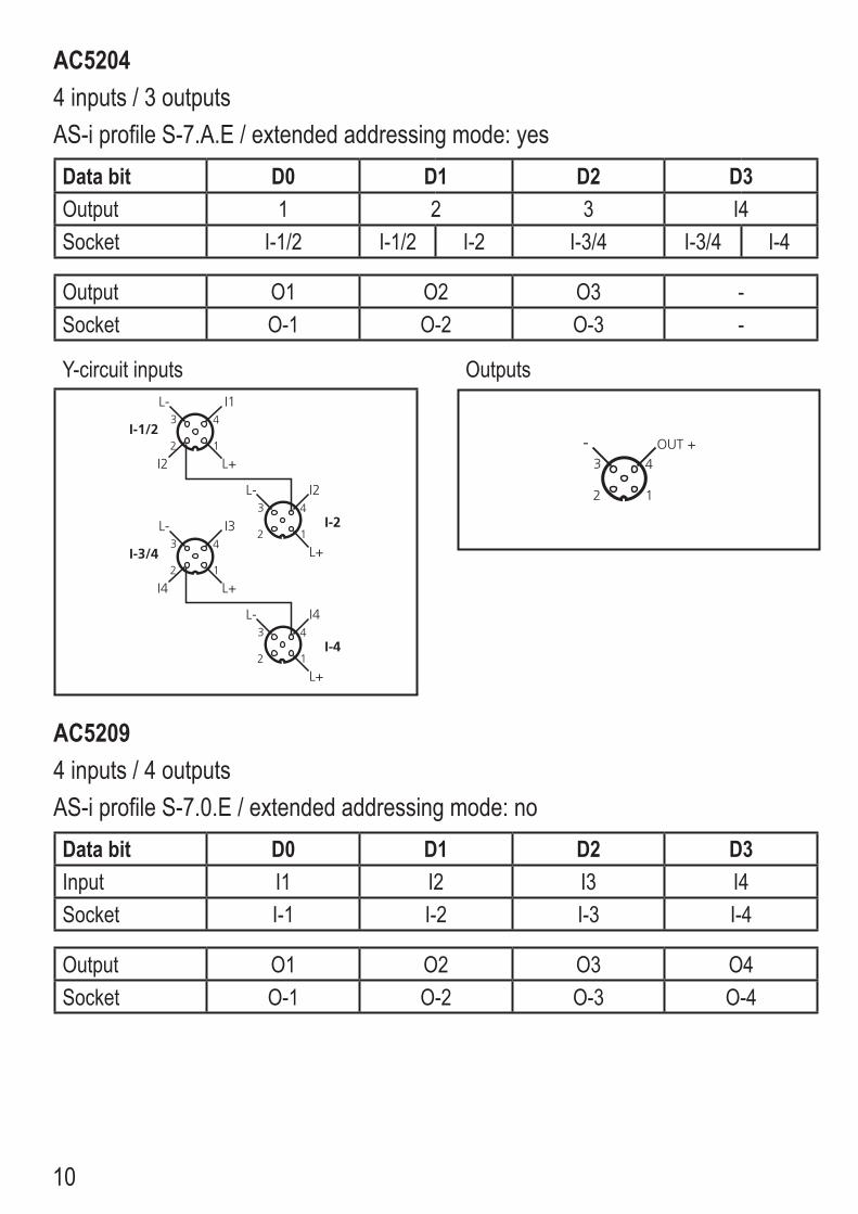
AC52124 inputs / 4 outputs (2 A)AS-i profile S-7.0.E / extended addressing mode: noData bit D0 D1 D2 D3Input I1 I2 I3 I4Socket I-1 I-2 I-3 I-4
Output O1 O2 O3 O4Socket O-1/2 O-1/2 O-2 O-3/4 O-3/4 O-4
Inputs Outputs Y-circuit
�
� �
�
��
��
�
� �
�
�
�
�
� �
�
�
����
��
�
� �
�
�
�
�
� �
�
�
����
��

12
AC5235, AC52364 inputs / 4 outputs AS-i profile S-7.A.7 / extended addressing mode: yesData bit D0 D1 D2 D3Input I1 I1 I3 I4Socket I-1/2 I-1/2 I-2 I-3/4 I-3/4 I-4
Output O1 O2 O3 O4Socket O-1/2 O-1/2 O-2 O-3/4 O-3/4 O-4
Y-circuit inputs Y-circuit outputs
��
�
� �
���
�
����
�
� �
���
�
�����
���
��
�
� �
���
�
����
�
� �
���
�
�����
���
�
� �
�
�
�
�
� �
�
�
����
��
�
� �
�
�
�
�
� �
�
�
����
��

13
UK
6 OperationAvoid build-up of dirt and dust on the upper and lower parts so that the locking mechanism is not affected.
LED yellow:• input / output switchedLED PWR green:• AS-i voltage supply okLED AUX green:• AUX voltage supply okLED FAULT red lights:• AS-i communication error, slave does not
participate in the "normal" exchange of data, e.g. slave address 0
LED FAULT red flashes:• peripheral fault, e.g. sensor supply / output overloaded or shorted
LED 1 yellow:• logic state of the outputs
Overload and short circuit of the input supply and the outputs are signalled as peripheral fault to the AS-i master (version 2.1 or higher).
7 Technical dataTechnical data and further information at www.ifm.com --> Select your country --> Data sheet direct