Embed Size (px)
Citation preview
1
The Tokyo Electric Power Company, Incorporated
Operating Data of Kashiwazaki-Kariwa Nuclear Power Station
at the Time of the Occurrence of Niigata-Chuetsu-Oki Earthquake
August 10, 2007The Tokyo Electric Power Company, Inc.
2007 The Tokyo Electric Power Company, Inc. All Rights ReservedC
2Tokyo Electric Power Co., Ltd.
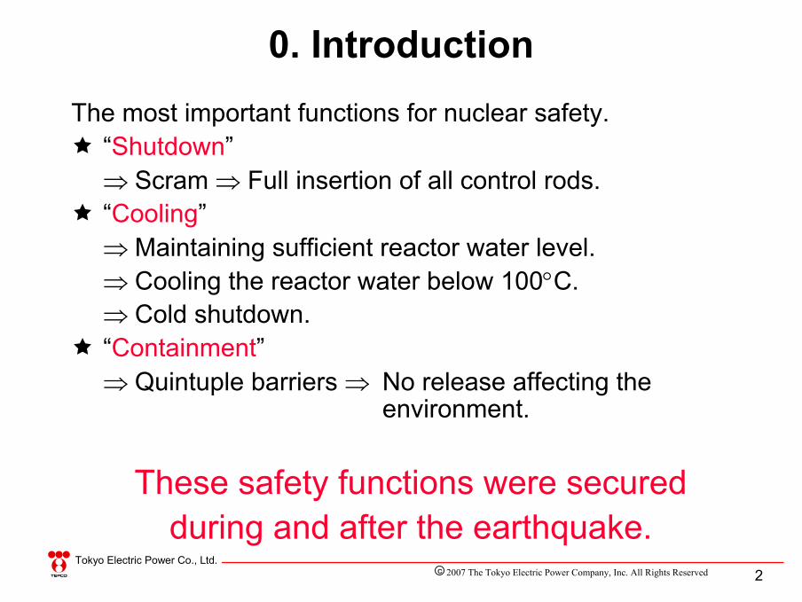
The most important functions for nuclear safety.“Shutdown”⇒ Scram ⇒ Full insertion of all control rods.“Cooling”⇒ Maintaining sufficient reactor water level.⇒ Cooling the reactor water below 100°C.⇒ Cold shutdown.“Containment”⇒ Quintuple barriers ⇒ No release affecting the
environment.
These safety functions were secured during and after the earthquake.
0. Introduction
2007 The Tokyo Electric Power Company, Inc. All Rights ReservedC

3Tokyo Electric Power Co., Ltd.
“Shutdown”, “Cooling” and “Containment”Shutdown
Cooling
Containment
Depressurization and cooling by condenser
Primary loop recirculation pump
Motor-driven reactor feed water pump
Circulating water pump
Low-pressure condensate pump
High-pressure condensate pump
Component cooling water system
Residual heat removal pump
Condenser
Reactor coolant is cooled by the residual heat removal system
Depressurization by opening the main steam relief valve
Containment by quintuple barriers1) Fuel pellets2) Fuel cladding3) Reactor pressure
vessel 4) Primary containment
vessel 5) Reactor building
Full insertion of all control rodsReactor building
Primary containment vessel
Reactor pressure vessel
GeneratorHighpressure turbine
Low pressure turbine
Hot wellPressure suppression pool water is cooled using the residual heat removal system
Pressure suppression
pool
2007 The Tokyo Electric Power Company, Inc. All Rights ReservedC

4Tokyo Electric Power Co., Ltd.
Niigata-Chuetsu-Oki Earthquake occurred at 10:30 on July 16, 2007.[Status of the units before and after the earthquake]
1. “Shutdown”
Automatic scramConstant operation at the rated thermal outputUnit 7
←Off-line for periodical inspectionUnit 6
←Off-line for periodical inspectionUnit 5
Automatic scramConstant operation at the rated thermal outputUnit 4
Automatic scramConstant operation at the rated thermal outputUnit 3
Automatic scramStart-up operation(subcritical state) Unit 2
←Off-line for periodical inspectionUnit 1
After the earthquakeBefore the earthquake
2007 The Tokyo Electric Power Company, Inc. All Rights ReservedC

5Tokyo Electric Power Co., Ltd.
Occurrence of the earthquake
Large seismic acceleration
Automatic scram of the reactor• Full insertion of all
control rods
1. “Shutdown”
Reactor building
Large seismic acceleration
Scram signal
Earthquake
Seismo-meter
2007 The Tokyo Electric Power Company, Inc. All Rights ReservedC

6Tokyo Electric Power Co., Ltd.
1. “Shutdown”
Reactors were shutdown
Printout of the computer immediately after the occurrence of the
earthquake (an example of K4)
At 10:13, Full insertion of all control rods
At 10:13, Automatic scram of the reactor
←
←
←
Unit 7
←
←
←
Unit 4
Printout of the computer *1
←
←
Unit 3
Chart *2
Printout of the
computer *1
Printout of the
computer *1
Unit 2
At 10:13, Large seismic acceleration
Generated signal
(Reference) [Records of signals relating to scram ]
The shift supervisor confirmed automatic scram of the reactor and the full insertion of all control rods on the control panel.
*1: Computer printouts record the generated scram signal or operations of the main devices. *2: Since the computer printout of Unit 2 did not take place for several minutes after the occurrence of the earthquake and/or
the printed time was not correct, data were taken from the neutron flux chart.
2007 The Tokyo Electric Power Company, Inc. All Rights ReservedC
7Tokyo Electric Power Co., Ltd.
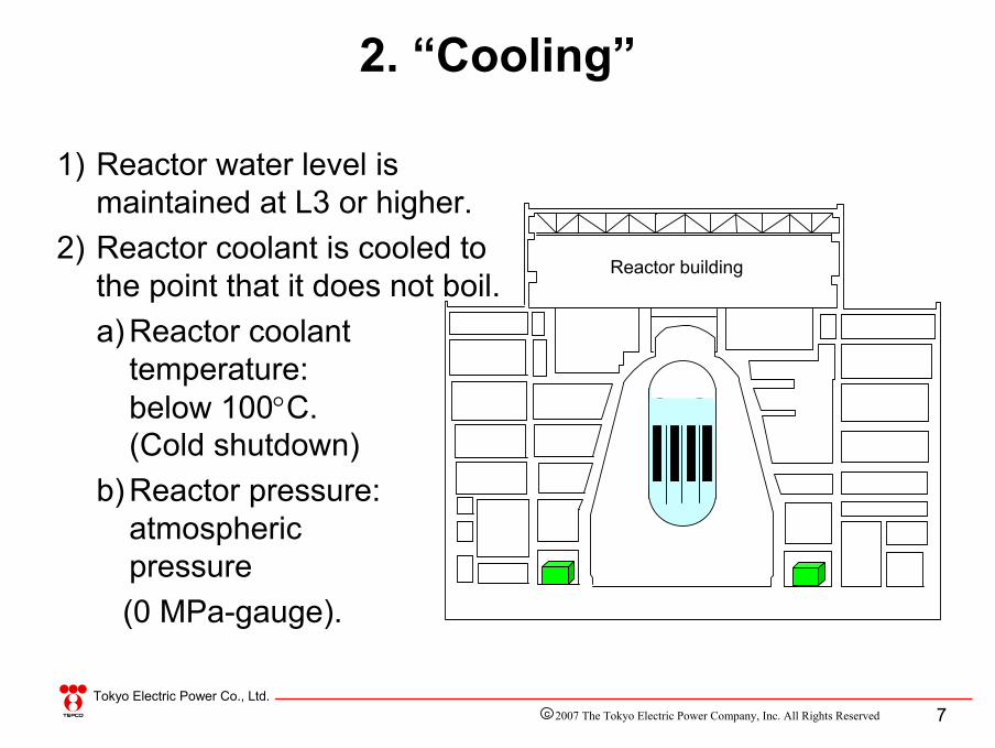
1) Reactor water level is maintained at L3 or higher.
2) Reactor coolant is cooled to the point that it does not boil.a) Reactor coolant
temperature: below 100°C. (Cold shutdown)
b) Reactor pressure: atmospheric pressure (0 MPa-gauge).
2. “Cooling”
Reactor building
2007 The Tokyo Electric Power Company, Inc. All Rights ReservedC
8Tokyo Electric Power Co., Ltd.
2. “Cooling”
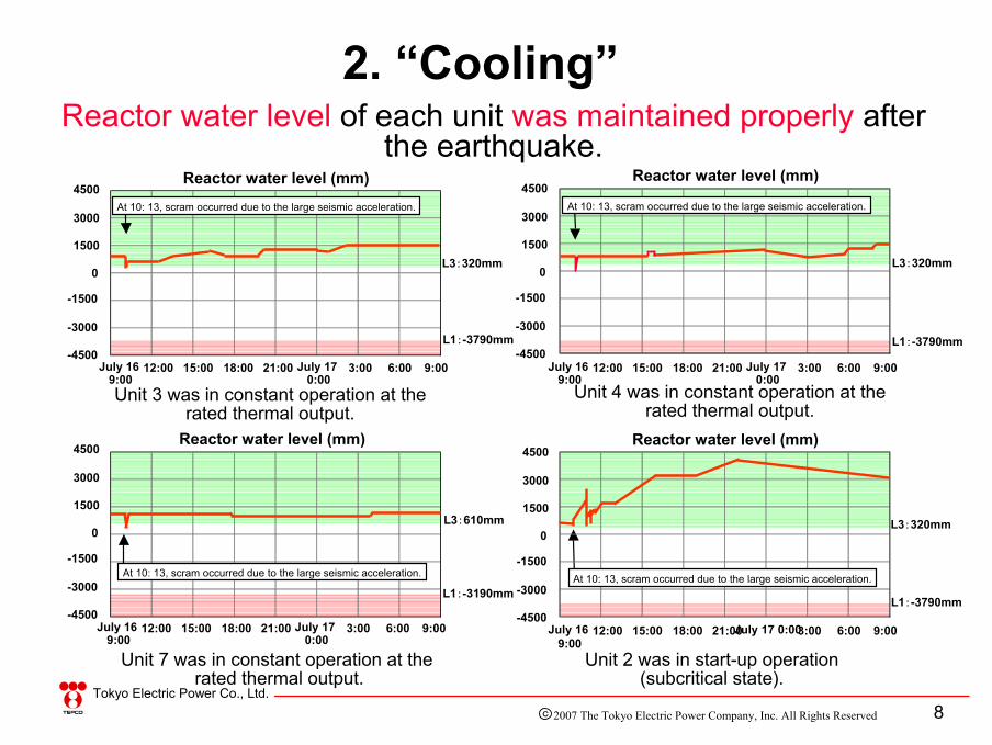
Unit 3 was in constant operation at the rated thermal output.
Unit 4 was in constant operation at the rated thermal output.
Unit 7 was in constant operation at the rated thermal output.
Unit 2 was in start-up operation (subcritical state).
Reactor water level of each unit was maintained properly after the earthquake.
Reactor water level (mm)
Reactor water level (mm)At 10: 13, scram occurred due to the large seismic acceleration.
L3:320mm
L3:320mm
Reactor water level (mm)
L3:320mm
Reactor water level (mm)
L3:610mm
L1:-3790mm
L1:-3190mm
4500
3000
1500
0
-1500
-3000
-4500
4500
3000
1500
0
-1500
-3000
-4500L1:-3790mm
4500
3000
1500
0
-1500
-3000
-4500
4500
3000
1500
0
-1500
-3000
-4500L1:-3790mm
At 10: 13, scram occurred due to the large seismic acceleration.
At 10: 13, scram occurred due to the large seismic acceleration.
At 10: 13, scram occurred due to the large seismic acceleration.
July 169:00
9:0021:0015:00 3:0018:0012:00 July 170:00
6:00 July 169:00
9:0021:0015:00 3:0018:0012:00 July 170:00
6:00
July 169:00
9:0021:0015:00 3:0018:0012:00 July 170:00
6:00 July 169:00
9:0021:0015:00 3:0018:0012:00 July 17 0:00 6:00
2007 The Tokyo Electric Power Company, Inc. All Rights ReservedC

9Tokyo Electric Power Co., Ltd.
[Fluctuation of the reactor water level immediately after the scram]When automatic scram of a reactor occurs during operation, full insertion of all control rods reduces the output and collapses the voids (steam bubbles), leading to an instantaneous drop of the reactor water level.This phenomenon occurred at the time of the earthquake.
2. “Cooling”
Full insertion of control rods due
to scram.
Collapse of voids.
The water level drops
instantaneously due to the collapse of
voids.
The water level control system operates and
the water level is restored
immediately.
L3:610mm
L1:-3190mm
4500
3000
1500
0
-1500
-3000
-4500
Unit 7 was in constant operation at the rated thermal output.
Reactor water level (mm)
At 10: 13, scram occurred due to the large seismic acceleration.
July 169:00
9:0021:0015:00 3:0018:0012:00 July 170:00
6:00
2007 The Tokyo Electric Power Company, Inc. All Rights ReservedC

10Tokyo Electric Power Co., Ltd.
Collapse of voids.
Full insertion of control rods due
to scram.
The water level lowers
instantaneously due to the collapse of
voids.
The water level control system
operates and the water level is
restored immediately.
1 2 3 4 5
Fluctuation of reactor water level immediately after the scram
2007 The Tokyo Electric Power Company, Inc. All Rights ReservedC

11Tokyo Electric Power Co., Ltd.
Reactor water level (mm)4500
3000
1500
-1500
-3000
-4500
At 10:13, scram due to the large seismic acceleration.
At 10:13, water level rose due to the trip of reactor water cleanup system.
At 10:28, trip of motor-driven reactor feed water pump (A) due to high reactor water level.
At 10:59, fluctuation due to the depressurization of the reactor using the turbine bypass valve.
At 11:06, completion of the full closing operation of the main steam isolation valve.
At 11:23 and 11:43, the main steam relief valve (Q) was closed.
At 11:40 and 11:43, the injection valve of low pressure core spray system was opened.
L3:320mm 0
July 169:00
11:0010:00 10:309:30 11:30 12:00
The reactor water level of Unit 2, which was in start-up operation (subcritical status), was maintained by the condensate pump. During the depressurization process using the main steam relief valve, cooling water was supplied using the low pressure core spray system in addition to the condensate pump and control rod drive pump.
At 11:17, 11:35, and 11:53, the main steam relief valve (Q) was opened.
2. “Cooling”
L1:-3790mm
At 11:34, manual start-up of the low pressure core spray pump.
Start of full closing operation of the main steam isolation valve.
2007 The Tokyo Electric Power Company, Inc. All Rights ReservedC

12Tokyo Electric Power Co., Ltd.
Condensate storage tank
Control rod drive hydraulic system
Generator
Primary loop recirculation pump
Motor-driven reactor feed water pump
Circulating water pump
Component cooling water system
High pressure core spray system
High pressure turbine
Low pressure turbine
Main exhaust stack
Off-gas treatment system
Residual heat removal system
Condenser
2. “Cooling”
Condensate pump
Main steam relief valve
Low pressure core spray system Pressure
suppression pool
Hot well
[Actual measures taken for water injection at Unit 2]
Condensasate demineralalizer
2007 The Tokyo Electric Power Company, Inc. All Rights ReservedC

13Tokyo Electric Power Co., Ltd.
Measures to maintain the reactor water level at L3 or higher in the process after the shutdown of the reactor include:
“Feed water system and condensate system”“Control rod drive hydraulic system”“Low pressure core spray system”“High pressure core spray system”
etc.
2. “Cooling”
From primary loop recirculation pumpTo primary loop recirculation pump
From feed water system
To turbine
Steam dryer
Steam-water separator
Core shroud
Fuel assembly
L1 (water level set for the operation of low pressure core
cooling system)Jet pump
From control rod drive hydraulic system
L2 (water level set for the operation of high pressure core
cooling system)
L3 (water level set for scram)
NWL (normal water level)
2007 The Tokyo Electric Power Company, Inc. All Rights ReservedC

14Tokyo Electric Power Co., Ltd.
2. “Cooling”
Unit 3 was in constant operation at the rated thermal output
(cold shutdown at 23:07, July 16, 2007)
Unit 4 was in constant operation at the rated thermal output
(cold shutdown at 6:54, July 17, 2007)
Unit 7 was in constant operation at the rated thermal output
(cold shutdown at 1:15, July 17, 2007)
Unit 2 was in start-up operation (subcritical state)
(cold shutdown at 19:40, July 16, 2007)
Reactor coolant of each unit was cooled below 100°C.
Temperature of reactor coolant (°C)
July 169:00
9:0021:0015:00 3:0018:0012:00 July 170:00
6:00
100
0
200
300
At 19:40, cold shutdown(reactor coolant temperature <100°C)
July 169:00
9:0021:0015:00 3:0018:0012:00 July 170:00
6:00
100
0
200
300
At 23:07, cold shutdown(reactor coolant temperature <100°C)
Temperature of reactor coolant (°C)
July 169:00
9:0021:0015:00 3:0018:0012:00 July 170:00
6:00
100
0
200
300At 6:54, cold shutdown(reactor coolant temperature<100°C)
Temperature of reactor coolant (°C)
July 169:00
9:0021:0015:00 3:0018:0012:00 July 170:00
6:00
100
0
200
300
At 1:15, cold shutdown(reactor coolant temperature <100°C)
Temperature of reactor coolant (°C)
At 10:13, scram occurred due to large seismic acceleration
At 10:13, scram occurred due to large seismic acceleration
At 10:13, scram occurred due to large seismic acceleration
At 10:13, scram occurred due to large seismic acceleration
2007 The Tokyo Electric Power Company, Inc. All Rights ReservedC

15Tokyo Electric Power Co., Ltd.
July 169:00
9:0021:0015:00 3:0018:0012:00 July 170:00
6:00
July 169:00
9:0021:0015:00 3:0018:0012:00 July 170:00
6:00
2. “Cooling”
Unit 3 was in constant operation at the rated thermal output
(depressurization completed at 23:07, July 16, 2007)
Unit 7 was in constant operation at the rated thermal output
(depressurization completed at 1:15, July 17, 2007)
Unit 2 was in start-up operation (subcritical state)
(depressurization completed at 19:40, July 16, 2007)
Reactor pressure of each unit was depressurized to atmospheric pressure (0MPa-gauge).
3.5
0
7.0
Reactor pressure (MPa)
At 10:13, scram occurred due to large seismic acceleration
3.5
0
7.0Reactor pressure (MPa)
Reactor pressure (MPa)
Reactor pressure (MPa)
July 169:00
9:0021:0015:00 3:0018:0012:00 July 170:00
6:00
July 169:00
21:0015:00 3:0018:0012:00 July 170:00
6:00
At 10:13, scram occurred due to large seismic acceleration
9:00
Unit 4 was in constant operationat the rated thermal output
(depressurization completed at 6:54, July 17, 2007)
3.5
7.07.5
3.5
0
7.0
At 10:13, scram occurred due to large seismic acceleration
At 10:13, scram occurred due to large seismic acceleration
2007 The Tokyo Electric Power Company, Inc. All Rights ReservedC

16Tokyo Electric Power Co., Ltd.
Measures to remove the decay heat after reactor scram are the following:1. Cooling using the turbine bypass valve.
Steam generated in the reactor is cooled in the condenser*1 via the turbine bypass valve.
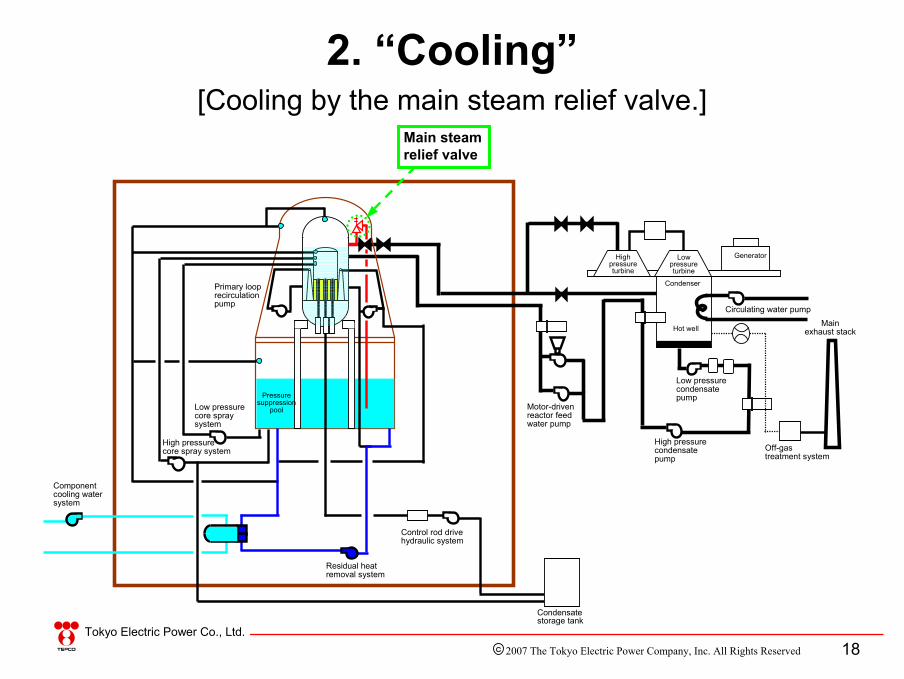
2. Cooling using the main steam relief valve.Steam generated in the reactor is cooled in the pressure suppression pool*2 via the main steam relief valve.*1: Direct cooling by seawater.*2: Indirect cooling by seawater through the residual
heat removal system and component cooling water system.
2. “Cooling”
2007 The Tokyo Electric Power Company, Inc. All Rights ReservedC

17Tokyo Electric Power Co., Ltd.
[Cooling by the turbine bypass valve.]Turbine bypass valve
2. “Cooling”
Condensate storage tank
Control rod drive hydraulic system
Generator
Primary loop recirculation pump
Motor-driven reactor feed water pump
Circulating water pump
Component cooling water system
High pressure core spray system
High pressure turbine
Low pressure turbine
Main exhaust stack
Off-gas treatment system
Residual heat removal system
Condenser
Pressure suppression
pool
Hot well
Low pressure condensate pump
Low pressure core spray system
High pressure condensate pump
2007 The Tokyo Electric Power Company, Inc. All Rights ReservedC
18Tokyo Electric Power Co., Ltd.
[Cooling by the main steam relief valve.]Main steam relief valve
2. “Cooling”
Condensate storage tank
Control rod drive hydraulic system
Primary loop recirculation pump
Motor-driven reactor feed water pump
Circulating water pump
Component cooling water system
High pressure core spray system
High pressure turbine
Low pressure turbine
Main exhaust stack
Off-gas treatment system
Residual heat removal system
Condenser
Pressure suppression
pool
Hot well
Low pressure condensate pump
Low pressure core spray system
High pressure condensate pump
Generator
2007 The Tokyo Electric Power Company, Inc. All Rights ReservedC

19Tokyo Electric Power Co., Ltd.
(actual operation)
[Units 3 and 4 were in constant operation at the rated thermal output] Operation carried out as specified in the procedure.
Cooled by the condenser via the turbine bypass valve. Water was fed to the reactor from the condenser hot well by the condensate pump.
When the temperature of reactor coolant decreased to around 100°C, the water was further cooled using the residual heat removal system shutdown cooling mode.
Since the common in-house boiler is used for Units 3 and 4 when maintaining the vacuum of the condenser, the operation of decay heat removal was carried out in the order of Unit 3 and Unit 4.
2. “Cooling”
2007 The Tokyo Electric Power Company, Inc. All Rights ReservedC
20Tokyo Electric Power Co., Ltd.
(actual operation)
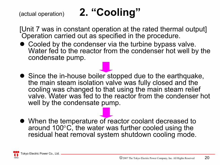
[Unit 7 was in constant operation at the rated thermal output] Operation carried out as specified in the procedure.
Cooled by the condenser via the turbine bypass valve. Water fed to the reactor from the condenser hot well by the condensate pump.
Since the in-house boiler stopped due to the earthquake, the main steam isolation valve was fully closed and the cooling was changed to that using the main steam relief valve. Water was fed to the reactor from the condenser hot well by the condensate pump.
When the temperature of reactor coolant decreased to around 100°C, the water was further cooled using the residual heat removal system shutdown cooling mode.
2. “Cooling”
2007 The Tokyo Electric Power Company, Inc. All Rights ReservedC

21Tokyo Electric Power Co., Ltd.
(actual operation) 2. “Cooling”[Unit 2 was in start-up operation (subcritical state)] Operation carried out as specified in the procedure.
Since the unit was in start-up operation, the flow of the main steam was low and the turbine bypass valve was fully closed.
The main steam isolation valve was fully closed and the cooling was changed to that using the main steam relief valve. The condensate pump and control rod drive pump as well as the low pressure core spray pump were started to inject water to the reactor from the pressure suppression pool.
Since decay heat was small, the reactor coolant temperature decreased as the reactor was depressurized. Water was fed to the reactor from the condensate demineralizer outlet by the control rod drive pump.
When the temperature of reactor coolant decreased to around 100°C, the water was further cooled using the residual heat removal system shutdown cooling mode.
2007 The Tokyo Electric Power Company, Inc. All Rights ReservedC

22Tokyo Electric Power Co., Ltd.
Sintered uranium fuel, in which most of the radioactive materials are confined.
About 350 pellets are encapsulated within a rigid metallic tube and radioactive noble gas emitted from the pellet is confined in the tube.
A vessel made of low-alloy steel with a thickness of about 16 cm. The vessel prevents radioactive materials from escaping from the reactor in case radioactive materials leak due to pinholes in the cladding tube.
A containment vessel with a wall thickness of about 3 cm, in which main components of the reactor are enclosed. This is a barrier in case radioactive materials escape from the reactor.
The outermost barrier is the reactor building made of concrete with a thickness of over 1 m. The reactor building is provided to fully assure the containment of radioactive materials.
3. “Containment”
The secondbarrier
The first barrier Pellet
Fuel cladding tube
Reactor pressure vessel
Primary containment vessel
The fifthbarrier Reactor building
The fourthbarrier
The thirdbarrier
2007 The Tokyo Electric Power Company, Inc. All Rights ReservedC
23Tokyo Electric Power Co., Ltd.
3. “Containment"
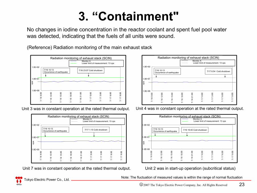
Note: The fluctuation of measured values is within the range of normal fluctuation
No changes in iodine concentration in the reactor coolant and spent fuel pool water was detected, indicating that the fuels of all units were sound.
(Reference) Radiation monitoring of the main exhaust stack
Unit 2 was in start-up operation (subcritical status)
Unit 3 was in constant operation at the rated thermal output. Unit 4 was in constant operation at the rated thermal output.
Unit 7 was in constant operation at the rated thermal output.
排気筒放射線モニタ(SCIN)
1.0E+00
1.0E+01
1.0E+02
7/16 9
:00
7/16 1
2:0
0
7/16 1
5:0
0
7/16 1
8:0
0
7/16 2
1:0
0
7/17 0
:00
7/17 3
:00
7/17 6
:00
7/17 9
:00
cp
s
モニタA測定指針の測定下限濃度:12cps
7/16 10:13 地震発生 7/16 19:40 冷温停止
排気筒放射線モニタ(SCIN)
1.0E+00
1.0E+01
1.0E+02
7/16 9
:00
7/16 1
2:0
0
7/16 1
5:0
0
7/16 1
8:0
0
7/16 2
1:0
0
7/17 0
:00
7/17 3
:00
7/17 6
:00
7/17 9
:00
cp
s
モニタA
測定指針の測定下限濃度:11cps
7/16 10:13 地震発生 7/17 1:15 冷温停止
排気筒放射線モニタ(SCIN)
1.0E+00
1.0E+01
1.0E+02
7/16 9
:00
7/16 1
2:0
0
7/16 1
5:0
0
7/16 1
8:0
0
7/16 2
1:0
0
7/17 0
:00
7/17 3
:00
7/17 6
:00
7/17 9
:00
cp
s
モニタA
測定指針の測定下限濃度:12cps
7/16 10:13 地震発生 7/17 6:54 冷温停止
排気筒放射線モニタ(SCIN)
1.0E+00
1.0E+01
1.0E+02
7/16 9
:00
7/16 1
2:0
0
7/16 1
5:0
0
7/16 1
8:0
0
7/16 2
1:0
0
7/17 0
:00
7/17 3
:00
7/17 6
:00
7/17 9
:00
cp
s
モニタA
測定指針の測定下限濃度:13cps
7/16 10:13 地震発生 7/16 23:07 冷温停止
Radiation monitoring of exhaust stack (SCIN)
Radiation monitoring of exhaust stack (SCIN)
Radiation monitoring of exhaust stack (SCIN)
Radiation monitoring of exhaust stack (SCIN)
Monitor ALower limit of measurement: 13 cps
Monitor A Lower limit of measurement: 13 cps
Monitor ALower limit of measurement: 13 cps
Monitor ALower limit of measurement: 13 cps
7/16 10:13 Occurrence of earthquake
7/16 23:07 Cold shutdown
7/16 10:13 Occurrence of earthquake 7/17 1:15 Cold shutdown 7/16 10:13
Occurrence of earthquake 7/16 19:40 Cold shutdown
7/16 10:13 Occurrence of earthquake 7/17 6:54 Cold shutdown
2007 The Tokyo Electric Power Company, Inc. All Rights ReservedC

24Tokyo Electric Power Co., Ltd.
3. “Containment”[Monitoring post]
感雨
0
単位:
7/16 9:00 7/16 12:00 7/16 15:00 7/16 18:00 7/16 21:00 7/17 0:00 7/17 3:00 7/17 6:00 7/17 9:00
MP-1
MP-2
MP-3
MP-4
MP-5
MP-6
MP-7
MP-8
MP-9
単位:nG/h
100
10,000
100,000
1,000,000
0
1,000
7/16 10:13 地震発生
モニタリングポストリアルタイムデータ(7月16日 9:00 ~ 7月17日 9:00)
感雨
Monitoring post real time data (from 9: 00, July 16 to 9:00, July 17)
Detection of precipitation
Unit: nG/h
At 10:13, July 16, occurrence of earthquake
2007 The Tokyo Electric Power Company, Inc. All Rights ReservedC

25Tokyo Electric Power Co., Ltd.
7/16 9:00 7/16 12:00 7/16 15:00 7/16 18:00 7/16 21:00 7/17 0:00 7/17 3:00 7/17 6:00 7/17 9:00
1号機
2号機
3号機
4号機
5号機
6号機
7号機
1,000
10,000
100,000
1,000,000
0
7/16 10:13 地震発生
単位:cpm
海水モニターリアルタイムデータ(7月16日 9:00 ~ 7月17日 9:00)
感雨
3. “Containment”[Seawater monitoring]
Seawater monitoring real-time data (from 9: 00, July 16 to 9:00, July 17)Detection of precipitation
Unit: cpm
At 10:13, July 16, occurrence of earthquake
Unit 1Unit 2Unit 3Unit 4Unit 5Unit 6Unit 7
2007 The Tokyo Electric Power Company, Inc. All Rights ReservedC

26Tokyo Electric Power Co., Ltd.
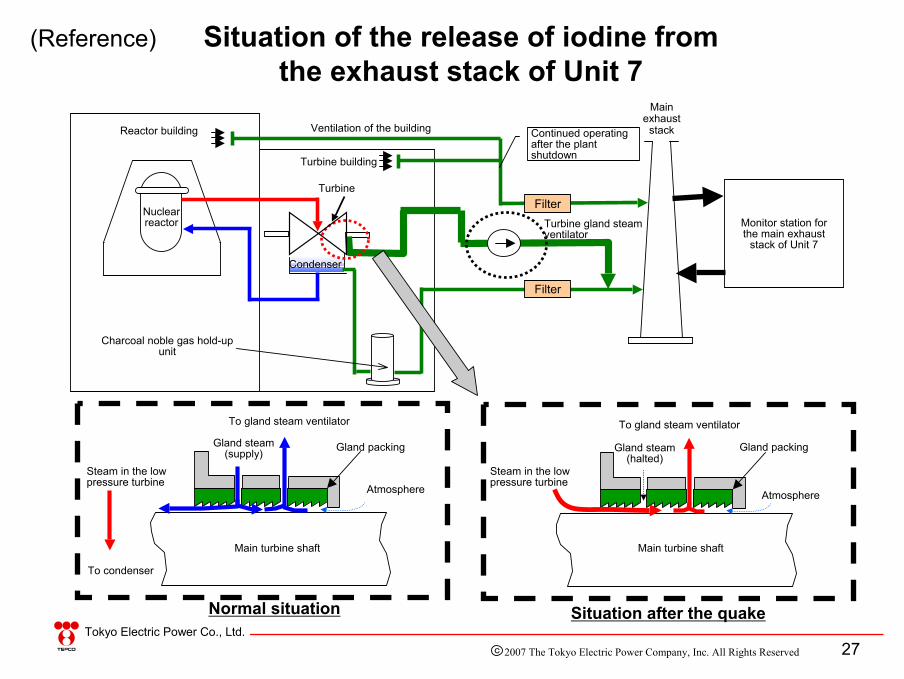
Total radioactivity: about 4×10⁸ BqRadiation dose from the above radioactivity : about 2×10⁻⁷ mSv(About one ten-millionth of the radiation that an average person
is exposed to from natural sources annually.)(About one millionth of the radiation received by a person in a
round-trip flight between Tokyo and New York.)
<Time series >• At around 13:00, July 17, iodine and radioactive particulates (chromium 51 and
cobalt 60) were detected in a periodical measurement (implemented once a week) of the main exhaust stack.
• Press release at 16:00 of the same day.
<Cause of occurrence>• It is presumed that radioactive materials were sucked out from the condenser and
subsequently released from the main stack due to the delay in shutting down the gland steam ventilator after automatic shutdown of the reactor.
• No radioactive material has been detected in measurements after July 19.
(Reference) Detection of radioactive materials in the main exhaust stack of Unit 7
2007 The Tokyo Electric Power Company, Inc. All Rights ReservedC
27Tokyo Electric Power Co., Ltd.
大気 タービン軸
主蒸気
グランド
コンデンサーへ
主復水器エバポレータより
高圧タービン軸封部概略図
主蒸気 大気 エバポレータ蒸気
Gland steam (halted)
(Reference) Situation of the release of iodine from the exhaust stack of Unit 7
Reactor building
Turbine building
Filter
Condenser
Turbine
Monitor station for the main exhaust
stack of Unit 7
Ventilation of the building
Turbine gland steam ventilator
Continued operating after the plant shutdown
Filter
Charcoal noble gas hold-up unit
大気 タービン軸
主蒸気
グランド
コンデンサーへ
主復水器エバポレータより
高圧タービン軸封部概略図
主蒸気 大気 エバポレータ蒸気
Steam in the low pressure turbine
Main turbine shaft
Atmosphere
To gland steam ventilator
Gland packingGland steam (supply)
To condenser
Normal situation Situation after the quake
Nuclear reactor
Main exhaust
stack
Steam in the low pressure turbine
Main turbine shaft
To gland steam ventilator
Gland packing
Atmosphere
2007 The Tokyo Electric Power Company, Inc. All Rights ReservedC

28Tokyo Electric Power Co., Ltd.
The most important functions for nuclear safety:“Shutdown” ⇒ Full insertion of all control
rods.“Cooling” ⇒ Cold shutdown.“Containment” ⇒ No release affecting the
environment.
4. Conclusion
All functions were satisfactory.
Stable cold shutdown conditions for all reactorshave been maintained after the earthquake.
2007 The Tokyo Electric Power Company, Inc. All Rights ReservedC


![Imperial College London · Web view[46]Nakagawa I, Nakamura K, Oyama M, et al. Long-term effects of the Niigata-Chuetsu earthquake in Japan on acute myocardial infarction mortality:](https://img.pdfslide.us/doc/110x75/60fd6ba216a64b68624d6975/imperial-college-london-web-view-46nakagawa-i-nakamura-k-oyama-m-et-al-long-term.jpg)


![The ABWR Project at Shimane-3, Japan · Concrete [m3]: U6: 200,000. ; U7: 167,000. • Owner’s Project Management Team in case of Kashiwazaki-Kariwa 6&7 (Source IAEA-TECDOC-1390.)](https://img.pdfslide.us/doc/110x75/604fef8edc0b566bb0411a4a/the-abwr-project-at-shimane-3-concrete-m3-u6-200000-u7-167000-a-owneras.jpg)