Embed Size (px)
Citation preview

Background Statement for SEMI Draft Document 5556Line Item Revision to SEMI S2-0712b, Environmental, Health, and Safety Guideline for Semiconductor Manufacturing EquipmentRevisions to §19 “Seismic Protection”
Notice: This background statement is not part of the balloted item. It is provided solely to assist the recipient in reaching an informed decision based on the rationale of the activity that preceded the creation of this Document.
Notice: Recipients of this Document are invited to submit, with their comments, notification of any relevant patented technology or copyrighted items of which they are aware and to provide supporting documentation. In this context, “patented technology” is defined as technology for which a patent has issued or has been applied for. In the latter case, only publicly available information on the contents of the patent application is to be provided.
Note: Additions are indicated by underline and deletions are indicated by strikethrough.
The voting result of this ballot will be reviewed by the Seismic Protection Task Force on March 26, 2015 and will be adjudicated at the Japan EHS Committee Meeting on April 17, 2015 at SEMI Japan office, Tokyo, Japan.
Background Statement
The Seismic Protection Task Force proposes the line item change to SEMI S2-0712b.
[History]At the start of this revision activity, majority of global EH&S community seemed to think unanimously that the current seismic forces should be updated as the UBC, which was basis for current criteria, had expired. It was originally agreed, as a result of discussions within Japan and with other regions, that those seismic force values should be updated to the most stringent set of seismic force calculation criteria among applicable local requirements (e.g., regulations, Standards) for regions in which known semiconductor manufacturing site is located. TF found, however, that any single requirement of any region, (e.g., ASCE < US>, European, Taiwan,Japan) couldn’t satisfy above condition as each requirement based on different assumptions and equations. While the highest calculated value of horizontal force is obtained based on one of those regional requirement, the highest vertical force may be obtained on another of them.
[Justification of this proposal]Furthermore, while current S2 criteria don’t give highest value for horizontal or vertical force, it is consistently high enough for both directions. Considering the fact that no equipment that was designed and anchored in accordance with current S2 seismic protection criteria reported to be overturned or significantly moved relatively to the floor in recent three earthquakes experienced in Japan (i.e., Great Hanshin-Awaji Earthquake,Niigata Chuetsu Earthquake and Great East Japan Earthquake), each of which affected location include volume production semiconductor fabs, the TF was convinced that S2 should be regarded as a field proven criteria.
For the reasons stated above, the TF decided to keep the seismic design loads criteria of SEMI S2 §19 and the anchoring method and updated other part for clarity and address some concerns of users. It was also decided to have typical regional criteria to be added for convenience in the Related Information section.
The ballot results will be reviewed and adjudicated at the meetings indicated in the table below. Check www.semi.org/standards under Calendar of Events for the latest update.
Line Item 1 Revision to §19 “Seismic Protection”Part A Revision to “§19 Seismic Protection”Part B Revision to “Related Information 4 Seismic Protection”
1
Review and Adjudication InformationTask Force Review Committee Adjudication
Group: Seismic protection Task Force Japan TC Chapter of GlobalEH&S Technical Committee
Date: March 26, 2015 April 17, 2015Time & Timezone: 10:00- JST 13:00- JSTLocation: SEMI Japan, Tokyo Office SEMI Japan, Tokyo OfficeCity, State/Country:
Tokyo, Japan Tokyo, Japan
Leader(s): Eiji Nakatani (SCREEN Semiconductor Solutions)
Supika Mashiro (Tokyo Electron)Hidetoshi Sakura (intel)Moray Crawford (Hatsuta)
Standards Staff: Naoko Tejima81.3.3222.5804
Naoko Tejima81.3.3222.5804
If you have any questions, please contact to the Seismic Protection Task Force leaders as shown below:Eiji Nakatani (Task Force Leader), [email protected],orNaoko Tejima, SEMI Japan staff, ntejima @semi.org.
2
Safety Checklist for SEMI Draft Document 5556Line Item Revision to SEMI S2-0712b, Environmental, Health, and Safety Guideline for Semiconductor Manufacturing EquipmentRevisions to §19 “Seismic Protection”
Developing/Revising BodyName/Type: Seismic Protection Task ForceTechnical Committee: Environment Health & Safety (EHS)Region: Japan
LeadershipPosition Last First AffiliationLeader Nakatani Eiji SCREEN Semiconductor Solutions
Documents, Conflicts, and ConsiderationSafety related codes, standards, and practices used in developing the safety guideline, and the manner in which each item was considered by the technical committee
# and Title Manner of ConsiderationASCE 7-10- Minimum Design Load for Buildings and Other Structures
Used as an example of RI of Seismic protection
TBC- Taiwan Building Code Used as an example of RI of Seismic protectionUBC-Uniform Building Code Used as an example of RI of Seismic protectionSeismic Design and Construction Guideline for Building Equipment
Used as an example of RI of Seismic protection
Known inconsistencies between the safety guideline and any other safety related codes, standards, and practices cited in the safety guideline # and Title Inconsistency with This Safety Guideline
Other conflicts with known codes, standards, and practices or with commonly accepted safety and health principles to the extent practical # and Title Nature of Conflict with This Safety Guideline
Participants and ContributorsLast First AffiliationAustin Lindy Salus EngineeringAihara Hisashi Office AiharaBarsky Joseph TUV RheiniandChoi Joyce NordsonChoo Choong Huat SeagateCosturos Ted Applied MaterialsCrawford Moray HatsutaCrocket Alan KLA-TencorDerbyshire Pauline TUV SUDErgete Nigusu Intertek GS3
Evanston Chris Salus EngineeringFaust Bruce TUV SUD AmericaFessler Mark TELFrankfurth Mark Cymer
3
Giles Andrew ESTECGreenberg Cliff Nikon PrecisionHamilton Jeff TELHayford James AMATHobbs Duncan SeagateHolbrook Glernn TUV SUDHosaka Yoshihiro DaifukuImaeda Yukihiro Murata MachineryJumper Steve Applied MaterialsKarl Edward Applied MaterialsKiley Andrew Applied MaterialsKlug Wolfgang TUV Rheinland GermanyKrauss Josh EHS2
Krauss Mark EHS2
Larsen Sean Lam ResearchLayman Curt SeagateLebouitz Kyle SPTSMashiro Supika Tokyo ElectronMcGreevey Mark DNS ElectronicsNakashima Norio Murata MachineryNarayanan Hari SeagateNishiguchi Naokatsu SCREEN Business Support SolutionsPlanting Bert ASMLPochon Stephan TUV RheinlandRenard Patrick GTATSakura Hidetoshi IntelSklar Eric Safety Guru,LLCSleiman Samir Brooks AutomationTanaka Hiroshi Murata MachineryVang Tou Lam ReseachVisty John Salus EngineeringYakimow Byron CymerYamanaka Kazuyoshi TakenakaWatanabe Shingo Tokyo Electron
The content requirements of this checklist are documented in Section 14.2 of the Regulations Governing SEMI Standards Committees.
4

DRAFTDocument Number: 5556
Date: 5/8/23
SEMI Draft Document 5556Line Item Revision to SEMI S2-0712b, Environmental, Health, and Safety Guideline for Semiconductor Manufacturing EquipmentRevisions to §19 “Seismic Protection”
1 Purpose1.1 This Safety Guideline is intended as a set of performance-based environmental, health, and safety (EHS) considerations for semiconductor manufacturing equipment.
2 Scope2.1 Applicability — This guideline applies to equipment used to manufacture, measure, assemble, and test semiconductor products.
2.2 Contents — This Document contains the following sections:
1. Purpose
2. Scope
3. Limitations
4. Referenced Standards and Documents
5. Terminology
6. Safety Philosophy
7. General Provisions
8. Evaluation Process
9. Documents Provided to User
10. Hazard Alert Labels
11. Safety Interlock Systems
12. Emergency Shutdown
13. Electrical Design
14. Fire Protection
15. Process Liquid Heating Systems
16. Ergonomics and Human Factors
17. Hazardous Energy Isolation
18. Mechanical Design
19. Seismic Protection
20. Automated Material Handlers
21. Environmental Considerations
22. Exhaust Ventilation
23. Chemicals
24. Ionizing Radiation
25. Non-Ionizing Radiation and Fields
This is a Draft Document of the SEMI International Standards program. No material on this page is to be construed as an official or adopted Standard or Safety Guideline. Permission is granted to reproduce and/or distribute this document, in whole or in part, only within the scope of SEMI International Standards committee (document development) activity. All other reproduction and/or distribution without the prior written consent of SEMI is prohibited.
Page 5 Doc. 5556 SEMI
Semiconductor Equipment and Materials International3081 Zanker RoadSan Jose, CA 95134-2127Phone: 408.943.6900, Fax: 408.943.7943

DRAFTDocument Number: 5556
Date: 5/8/23
26. Lasers
27. Sound Pressure Level
28. Related Documents
Appendix 1 — Design Guidelines for Equipment Using Liquid Chemicals
Appendix 2 — Ionizing Radiation Test Validation
Appendix 3 — Exposure Criteria and Test Methods for Non-Ionizing Radiation (Other than Laser) and Electromagnetic Fields
Appendix 4 — Fire Protection: Flowchart for Selecting Materials of Construction
Appendix 5 — Laser Data Sheet – SEMI S2
2.3 Precedence of Sectional Requirements — In the case of conflict between provisions in different sections of this guideline, the section or subsection specifically addressing the technical issue takes precedence over the more general section or subsection.
NOTICE: SEMI Standards and Safety Guidelines do not purport to address all safety issues associated with their use. It is the responsibility of the users of the Documents to establish appropriate safety and health practices, and determine the applicability of regulatory or other limitations prior to use.
3 LimitationsNOTICE: Revisions to §3 will be effective upon the July 2015 publication as shown in Delayed Revisions Section 1. The global Environmental Health & Safety Technical Committee has voted that the revision is OPTIONAL before the Effective Date.
3.1 This guideline is intended for use by supplier and user as a reference for EHS considerations. It is not intended to be used to verify compliance with local regulatory requirements.
3.2 It is not the philosophy of this guideline to provide all of the detailed EHS design criteria that may be applied to semiconductor manufacturing equipment. This guideline provides industry-specific criteria, and refers to some of the many international codes, regulations, standards, and specifications that should be considered when designing semiconductor manufacturing equipment.
3.3 Existing models and subsystems should continue to meet the provisions of SEMI S2-93A. Models with redesigns that significantly affect the EHS aspects of the equipment should conform to the latest version of SEMI S2. This guideline is not intended to be applied retroactively.
3.4 In many cases, references to standards have been incorporated into this guideline. These references do not imply applicability of the entire standards, but only of the sections referenced.
4 Referenced Standards and Documents4.1 SEMI Standards and Safety Guidelines
SEMI E6 — Guide for Semiconductor Equipment Installation Documentation
SEMI F5 — Guide for Gaseous Effluent Handling
SEMI F14 — Guide for the Design of Gas Source Equipment Enclosures
SEMI F15 — Test Method (SF6 Tracer Gas) for Enclosures Has Been Moved to SEMI S6
SEMI S1 — Safety Guideline for Equipment Safety Labels
SEMI S3 — Safety Guideline for Process Liquid Heating System
SEMI S6 — EHS Guideline for Exhaust Ventilation of Semiconductor Manufacturing Equipment
SEMI S7 — Safety Guidelines for Environmental, Safety, and Health (ESH) Evaluation of Semiconductor Manufacturing Equipment
SEMI S8 — Safety Guidelines for Ergonomics Engineering of Semiconductor Manufacturing Equipment
This is a Draft Document of the SEMI International Standards program. No material on this page is to be construed as an official or adopted Standard or Safety Guideline. Permission is granted to reproduce and/or distribute this document, in whole or in part, only within the scope of SEMI International Standards committee (document development) activity. All other reproduction and/or distribution without the prior written consent of SEMI is prohibited.
Page 6 Doc. 5556 SEMI
Semiconductor Equipment and Materials International3081 Zanker RoadSan Jose, CA 95134-2127Phone: 408.943.6900, Fax: 408.943.7943
DRAFTDocument Number: 5556
Date: 5/8/23
SEMI S10 — Safety Guideline for Risk Assessment and Risk Evaluation Process
SEMI S12 — Guidelines for Equipment Decontamination
SEMI S13 — Environmental, Health and Safety Guideline for Documents Provided to the Equipment User for Use with Semiconductor Manufacturing Equipment
SEMI S14 — Safety Guidelines for Fire Risk Assessment and Mitigation for Semiconductor Manufacturing Equipment
SEMI S22 — Safety Guideline for the Electrical Design of Semiconductor Manufacturing Equipment
4.2 ANSI Standards1
ANSI/RIA R15.06 — Industrial Robots and Robot Systems – Safety Requirements
ANSI/ISA S84.01 — Application of Safety Instrumented Systems for the Process Industry
4.3 CEN/CENELEC Standards2
CEN EN 775 — Manipulating Industrial Robots – Safety
CEN EN 1050 — Safety of Machinery – Principles of Risk Assessment
CEN EN 1127-1 — Explosive Atmospheres – Explosion Prevention and Protection – Part 1: Basic Concepts and Methodology
4.4 DIN Standards3
DIN V VDE 0801 — Principles for Computers in Safety-Related Systems
4.5 IEC Standards4
IEC 60825-1 — Safety of Laser Products – Part 1: Equipment Classification, Requirements
IEC 61010-1 — Safety Requirements for Electrical Equipment for Measurement, Control, and Laboratory Use – Part 1: General Requirements
IEC 61508 — Functional Safety of Electrical/Electronic/Programmable Electronic Safety-Related Systems
IEEE Standards5
IEEE C95.1 — Standard for Safety Levels with Respect to Human Exposure to Radio Frequency Electromagnetic Fields, 3 kHz to 300 GHz
4.6 ISO Standards6
ISO 10218-1 — Robots for Industrial Environments – Safety Requirements – Part 1: Robot
ISO 13849-1 — Safety of Machinery – Safety-Related Parts of Control Systems – Part 1: General Principles for Design
1 American National Standards Institute, 25 West 43rd Street, New York, NY 10036, USA; Telephone: 212.642.4900, Fax: 212.398.0023, http://www.ansi.org2 European Committee for Standardization, Avenue Marnix 17, B-1000 Brussels; Telephone: 32.2.550.08.11, Fax: 32.2.550.08.19, http://www.cen.eu3 Deutsches Institut für Normung e.V., Available from Beuth Verlag GmbH, Burggrafenstrasse 4-10, D-10787 Berlin, Germany; http://www.din.de4 International Electrotechnical Commission, 3 rue de Varembé, Case Postale 131, CH-1211 Geneva 20, Switzerland; Telephone: 41.22.919.02.11, Fax: 41.22.919.03.00, http://www.iec.ch5 Institute of Electrical and Electronics Engineers, 3 Park Avenue, 17th Floor, New York, NY 10016-5997, USA; Telephone: 212.419.7900, Fax: 212.752.4929, http://www.ieee.org6 International Organization for Standardization, ISO Central Secretariat, 1 rue de Varembé, Case postale 56, CH-1211 Geneva 20, Switzerland; Telephone: 41.22.749.01.11, Fax: 41.22.733.34.30, http://www.iso.ch
This is a Draft Document of the SEMI International Standards program. No material on this page is to be construed as an official or adopted Standard or Safety Guideline. Permission is granted to reproduce and/or distribute this document, in whole or in part, only within the scope of SEMI International Standards committee (document development) activity. All other reproduction and/or distribution without the prior written consent of SEMI is prohibited.
Page 7 Doc. 5556 SEMI
Semiconductor Equipment and Materials International3081 Zanker RoadSan Jose, CA 95134-2127Phone: 408.943.6900, Fax: 408.943.7943
DRAFTDocument Number: 5556
Date: 5/8/23
4.7 NFPA Standards7
NFPA 12 — Standard on Carbon Dioxide Extinguishing Systems
NFPA 13 — Standard for Installation of Sprinkler Systems
NFPA 72 — National Fire Alarm Code
NFPA 497 — Recommended Practice for the Classification of Flammable Liquids, Gases, or Vapors and of Hazardous (Classified) Locations for Electrical Installations in Chemical Process Areas
NFPA 704 — Standard System for the Identification of the Hazards of Materials for Emergency Response
NFPA 2001 — Standard on Clean Agent Fire Extinguishing Systems
4.8 Underwriters Laboratories Standards8
UL 508A — Industrial Control Panel
4.9 US Code of Federal Regulations9
21 CFR Parts 1000-1050 — Food and Drug Administration/Center for Devices and Radiological Health (FDA/CDRH), Performance Standards for Electronic Products, Title 21 Code of Federal Regulations, Parts 1000-1050
4.10 Other Standards and Documents
ACGIH, Industrial Ventilation Manual10
ASHRAE Standard 110 — Method of Testing Performance of Laboratory Fume Hoods11
Burton, D.J., Semiconductor Exhaust Ventilation Guidebook12
Uniform Building Code™ (UBC)13
Uniform Fire Code™14
NOTICE: Unless otherwise indicated, all documents cited shall be the latest published versions.
5 Terminology5.1 Abbreviations and Acronyms
5.1.1 ACGIH® — American Conference of Governmental Industrial Hygienists (ACGIH is a registered trademark of the American Conference of Governmental Industrial Hygienists.)
5.1.2 ASHRAE — American Society of Heating, Refrigeration, and Air Conditioning Engineers
5.1.3 MPE — maximum permissible exposure
5.1.4 NOHD — nominal ocular hazard distance
5.2 Definitions
1: Composite reports using portions of reports based upon earlier versions of SEMI S2 and SEMI S10 may require understanding of the SEMI S2-0703 or SEMI S10-1296 definitions for the terms hazard, likelihood, mishap, severity, and risk.7 National Fire Protection Association, 1 Batterymarch Park, Quincy, MA 02269, USA; Telephone: 617.770.3000, Fax: 617.770.0700, http://www.nfpa.org8 Underwriters Laboratory, 2600 N.W. Lake Road, Camas, WA 98607-8542, USA; Telephone: 877.854.3577, Fax: 360.817.6278, http://www.ul.com9 United States Food and Drug Administration/ Center for Devices and Radiological Health (FDA/CDRH). Available from FDA/CDRH; http:// www.accessdata.fda.gov/scripts/cdrh/cfdocs/cfcfr/cfrsearch.cfm 10 ACGIH, 1330 Kemper Meadow Road, Cincinnati, OH 45240, USA. http:// www.acgih.org 11 ASHRAE, 1791 Tullie Circle, NE, Atlanta, GE 30329, USA. http:// www.ashrae.org 12 IVE, Inc., 2974 South Oakwood, Bountiful, UT 84010, USA. http:// www.eburton.com 13 International Conference of Building Officials, 5360 Workman Mill Road, Whittier, CA 90601-2298, USA. http:// www.icbo.org 14 International Fire Code Institute, 5360 Workman Mill Road, Whittier, CA 90601-2298, USA. http:// www.ifci.org
This is a Draft Document of the SEMI International Standards program. No material on this page is to be construed as an official or adopted Standard or Safety Guideline. Permission is granted to reproduce and/or distribute this document, in whole or in part, only within the scope of SEMI International Standards committee (document development) activity. All other reproduction and/or distribution without the prior written consent of SEMI is prohibited.
Page 8 Doc. 5556 SEMI
Semiconductor Equipment and Materials International3081 Zanker RoadSan Jose, CA 95134-2127Phone: 408.943.6900, Fax: 408.943.7943

DRAFTDocument Number: 5556
Date: 5/8/23
5.2.1 abort switch — a switch that, when activated, interrupts the activation sequence of a fire detection or fire suppression system.
accredited testing laboratory — an independent organization dedicated to the testing of components, devices, or systems that is recognized by a governmental or regulatory body as competent to perform evaluations based on established safety standards.
5.2.2 baseline — for the purposes of this Document, “baseline” refers to operating conditions, including process chemistry, for which the equipment was designed and manufactured.
5.2.3 breathing zone — imaginary globe, of 600 mm (2 ft.) radius, surrounding the head.
5.2.4 capture velocity — the air velocity that at any point in front of the exhausted hood or at the exhausted hood opening is necessary to overcome opposing air currents and to capture the contaminated air at that point by causing it to flow into the exhausted hood.
5.2.5 carcinogen — confirmed or suspected human cancer-causing agent as defined by the International Agency for Research on Cancer (IARC) or other recognized entities.
5.2.6 chemical distribution system — the collection of subsystems and components used in a semiconductor manufacturing facility to control and deliver process chemicals from source to point of use for wafer manufacturing processes.
5.2.7 cleanroom — a room in which the concentration of airborne particles is controlled to specific limits.
5.2.8 combustible material — for the purpose of this guideline, a combustible material is any material that does propagate flame (beyond the ignition zone with or without the continued application of the ignition source) and does not meet the definition in this section for noncombustible material. See also the definition for noncombustible material.
5.2.9 equipment — a specific piece of machinery, apparatus, process module, or device used to execute an operation. The term “equipment” does not apply to any product (e.g., substrates, semiconductors) that may be damaged as a result of equipment failure.
5.2.10 face velocity — velocity at the cross-sectional entrance to the exhausted hood.
5.2.11 facilitization — the provision of facilities or services.
5.2.12 fail-safe — designed so that a failure does not result in an increased risk.
2: For example, a fail-safe temperature limiting device would indicate an out-of-control temperature if it were to fail. This might interrupt a process, but would be preferable to the device indicating that the temperature is within the control limits, regardless of the actual temperature, in case of a failure.
5.2.13 fail-to-safe equipment control system (FECS) — a safety-related programmable system of control circuits designed and implemented for safety functions in accordance with recognized standards such as ISO 13849-1 (EN 954-1) or IEC 61508, ANSI SP 84. These systems (e.g., safety programmable logic controller (PLC), safety-related input and output (I/O) modules) diagnose internal and external faults and react upon detected faults in a controlled manner in order to bring the equipment to a safe state.
3: A FECS is a subsystem to a programmable electronic system (PES) as defined in IEC 61508-4 Definitions.
4: Related Information 13 provides additional information on applications of FECS design.
5.2.14 failure — the termination of the ability of an item to perform a required function. Failure is an event, as distinguished from “fault,” which is a state.
5.2.15 fault — the state of an item characterized by inability to perform a required function, excluding the inability during preventive maintenance or other planned actions, or due to lack of external resources.
5.2.16 fault-tolerant — designed so that a reasonably foreseeable single point failure does not result in an unsafe condition.
5.2.17 flammable gas — any gas that forms an ignitable mixture in air at 20C (68F) and 101.3 kPa (14.7 psia).
5.2.18 flammable liquid — a liquid having a flash point below 37.8C (100F).
This is a Draft Document of the SEMI International Standards program. No material on this page is to be construed as an official or adopted Standard or Safety Guideline. Permission is granted to reproduce and/or distribute this document, in whole or in part, only within the scope of SEMI International Standards committee (document development) activity. All other reproduction and/or distribution without the prior written consent of SEMI is prohibited.
Page 9 Doc. 5556 SEMI
Semiconductor Equipment and Materials International3081 Zanker RoadSan Jose, CA 95134-2127Phone: 408.943.6900, Fax: 408.943.7943

DRAFTDocument Number: 5556
Date: 5/8/23
5.2.19 flash point — the minimum temperature at which a liquid gives off sufficient vapor to form an ignitable mixture with air near the surface of the liquid, or within the test vessel used.
5.2.20 gas cylinder cabinet — cabinet used for housing gas cylinders, and connected to gas distribution piping or to equipment using the gas. Synonym: gas cabinet.
5.2.21 gas panel — an arrangement of fluid handling components (e.g., valves, filters, mass flow controllers) that regulates the flow of fluids into the process. Synonyms: gas jungle, jungle, gas control valves, valve manifold.
5.2.22 gas panel enclosure — an enclosure designed to contain leaks from gas panel(s) within itself. Synonyms: jungle enclosure, gas box, valve manifold box.
5.2.23 harm — physical injury or damage to health of people, or damage to equipment, buildings, or environments.
5.2.24 hazard — condition that has the potential to cause harm.
hazardous electrical power — power levels equal to or greater than 240 VA.
5.2.25 hazardous production material (HPM) — a solid, liquid, or gas that has a degree-of-hazard rating in health, flammability, or reactivity of class 3 or 4 as ranked by NFPA 704 and which is used directly in research, laboratory, or production processes that have as their end product materials that are not hazardous.
5.2.26 hazardous voltage — unless otherwise defined by an appropriate international standard applicable to the equipment, voltages greater than 30 volts rms, 42.4 volts peak, 60 volts dc are defined in this Document as hazardous voltage.
5: The specified levels are based on normal conditions in a dry location.
5.2.27 hinged load — a load supported by a hinge such that the hinge axis is not vertical.
hood — in the context of § 22 of this guideline, “hood” means a shaped inlet designed to capture contaminated air and conduct it into an exhaust duct system.
5.2.28 incompatible — as applied to chemicals: in the context of §23 of this guideline, describes chemicals that, when combined unintentionally, may react violently or in an uncontrolled manner, releasing energy that may create a hazardous condition.
5.2.29 intended reaction product — chemicals that are produced intentionally as a functional part of the semiconductor manufacturing process.
5.2.30 interlock — a mechanical, electrical or other type of device or system, the purpose of which is to prevent or interrupt the operation of specified machine elements under specified conditions.
5.2.31 ionizing radiation — alpha particles, beta particles, gamma rays, X-rays, neutrons, high-speed electrons, high-speed protons, and other particles capable of producing ions in human tissue.
5.2.32 laser — any device that can be made to produce or amplify electromagnetic radiation in the wavelength range from 180 nm to 1 mm primarily by the process of controlled stimulated emission.
5.2.33 laser product — any product or assembly of components that constitutes, incorporates, or is intended to incorporate a laser or laser system (including laser diode), and that is not sold to another manufacturer for use as a component (or replacement for such component) of an electronic product.
5.2.34 laser source — any device intended for use in conjunction with a laser to supply energy for the excitation of electrons, ions, or molecules. General energy sources, such as electrical supply mains, should not be considered to be laser energy sources.
5.2.35 laser system — a laser in combination with an appropriate laser energy source, with or without additional incorporated components.
5.2.36 lifting accessory — a component (e.g., eyehook, shackle, hoist ring, wire rope, chain, or eyebolt) which is part of a lifting fixture or is attached directly between the lifting device and the load in order to lift it.
5.2.37 lifting device — a mechanical or electro-mechanical structure that is provided for the purpose of raising and lowering a load during maintenance or service tasks, and may be capable of moving the load in one or more horizontal directions.
This is a Draft Document of the SEMI International Standards program. No material on this page is to be construed as an official or adopted Standard or Safety Guideline. Permission is granted to reproduce and/or distribute this document, in whole or in part, only within the scope of SEMI International Standards committee (document development) activity. All other reproduction and/or distribution without the prior written consent of SEMI is prohibited.
Page 10 Doc. 5556 SEMI
Semiconductor Equipment and Materials International3081 Zanker RoadSan Jose, CA 95134-2127Phone: 408.943.6900, Fax: 408.943.7943

DRAFTDocument Number: 5556
Date: 5/8/23
5.2.38 lifting equipment — lifting devices, lifting fixtures and lifting accessories.
5.2.39 lifting fixture — a mechanical device or an assembly of lifting accessories (e.g., hoisting yoke, wire rope sling, webbing sling, or chain assembly) placed between the lifting device (but not permanently attached to it) and the load, in order to attach them to each other.
5.2.40 likelihood — the expected frequency with which harm will occur. Usually expressed as a rate (e.g., events per year, per product, or per substrate processed).
5.2.41 local exhaust ventilation — local exhaust ventilation systems operate on the principle of capturing a contaminant at or near its source and moving the contaminant to the external environment, usually through an air cleaning or a destructive device. It is not to be confused with laminar flow ventilation. Synonyms: LEV, local exhaust, main exhaust, extraction system, module exhaust, individual exhaust.
5.2.42 lower explosive limit — the minimum concentration of vapor in air at which propagation of flame will occur in the presence of an ignition source. Synonyms: LEL, lower flammability limit (LFL).
5.2.43 maintenance — planned or unplanned activities intended to keep equipment in good working order. See also the definition for service.
5.2.44 mass balance — a qualitative, and where possible, quantitative, specification of mass flow of input and output streams (including chemicals, gases, water, de-ionized water, compressed air, nitrogen, and by-products), in sufficient detail to determine the effluent characteristics and potential treatment options.
5.2.45 material safety data sheet (MSDS) — written or printed material concerning chemical elements and compounds, including hazardous materials, prepared in accordance with applicable standards.
5.2.46 maximum permissible exposure (MPE) — level of laser radiation to which, under normal circumstances, persons may be exposed without suffering adverse effects.
5.2.47 nominal ocular hazard distance (NOHD) — distance at which the beam irradiance or radiant exposure equals the appropriate corneal maximum permissible exposure (MPE).
6: Examples of such standards are USA government regulation 29 CFR 1910.1200, and Canadian WHMIS (Workplace Hazardous Material Information System).
5.2.48 noncombustible material — a material that, in the form in which it is used and under the conditions anticipated, will not ignite, burn, support combustion, or release flammable vapors when subjected to fire or heat. Typical noncombustible materials are metals, ceramics, and silica materials (e.g., glass and quartz). See also the definition for combustible material.
5.2.49 non-ionizing radiation — forms of electro-magnetic energy that do not possess sufficient energy to ionize human tissue by means of the interaction of a single photon of any given frequency with human tissue. Non-ionizing radiation is customarily identified by frequencies from zero hertz to 3 × 10¹⁵ hertz (wavelengths ranging from infinite to 100 nm). This includes: static fields (frequencies of 0 hertz and infinite wavelengths); extremely low frequency fields (ELF), which includes power frequencies; subradio-frequencies; radiofrequency/microwave energy; and infrared, visible, and ultraviolet energies.
5.2.50 non-recycling, deadman-type abort switch — a type of abort switch that must be constantly held closed for the abort of the fire detection or suppression system. In addition, it does not restart or interrupt any time delay sequence for the detection or suppression system when it is activated.
5.2.51 occupational exposure limits (OELs) — for the purpose of this Document, OELs are generally established on the basis of an eight hour workday. Various terms are used to refer to OELs, such as permissible exposure levels, Threshold Limit Values, maximum acceptable concentrations, maximum exposure limits, and occupational exposure standards. However, the criteria used in determining OELs can differ among the various countries that have established values. Refer to the national bodies responsible for the establishment of OELs. (Threshold Limit Value is a registered trademark of the American Conference of Governmental Industrial Hygienists.)
5.2.52 operator — a person who interacts with the equipment only to the degree necessary for the equipment to perform its intended function.
5.2.53 parts-cleaning hood — exhausted hood used for the purpose of cleaning parts or equipment. Synonym: equipment cleaning hood.
This is a Draft Document of the SEMI International Standards program. No material on this page is to be construed as an official or adopted Standard or Safety Guideline. Permission is granted to reproduce and/or distribute this document, in whole or in part, only within the scope of SEMI International Standards committee (document development) activity. All other reproduction and/or distribution without the prior written consent of SEMI is prohibited.
Page 11 Doc. 5556 SEMI
Semiconductor Equipment and Materials International3081 Zanker RoadSan Jose, CA 95134-2127Phone: 408.943.6900, Fax: 408.943.7943

DRAFTDocument Number: 5556
Date: 5/8/23
5.2.54 placed on the market — made physically available, regardless of the legal aspects of the act of transfer (loan, gift, sale, hire).
5.2.55 positive-opening — as applied to electromechanical control devices. The achievement of contact separation as a direct result of a specified movement of the switch actuator through non-resilient members (i.e., contact separation is not dependent upon springs).
5.2.56 potentially hazardous non-ionizing radiation emissions — for the purposes of this guideline, non-ionizing radiation emissions outside the limits shown in Appendix 4 are considered potentially hazardous.
5.2.57 pyrophoric material — a chemical that will spontaneously ignite in air at or below a temperature of 54.4 C (130F).
5.2.58 radio frequency (rf) — electromagnetic energy with frequencies ranging from 3 kHz to 300 GHz. Microwaves are a portion of rf extending from 300 MHz to 300 GHz.
5.2.59 readily accessible — capable of being reached quickly for operation or inspection, without requiring climbing over or removing obstacles, or using portable ladders, chairs, etc.
5.2.60 recognized — as applied to standards; agreed to, accepted, and practiced by a substantial international consensus.
5.2.61 rem — unit of dose equivalent. Most instruments used to measure ionizing radiation read in dose equivalent (rems or sieverts). 1 rem = 0.01 sievert.
5.2.62 reproductive toxicants — chemicals that are confirmed or suspected to cause statistically significant increased risk for teratogenicity, developmental effects, or adverse effects on embryo viability or on male or female reproductive function at doses that are not considered otherwise maternally or paternally toxic.
5.2.63 residual — as applied to risks or hazards: that which remains after engineering, administrative, and work practice controls have been implemented.
5.2.64 risk — the expected magnitude of losses from a hazard, expressed in terms of severity and likelihood.
5.2.65 safe shutdown condition — a condition in which all hazardous energy sources are removed or suitably contained and hazardous production materials are removed or contained, unless this results in additional hazardous conditions.
5.2.66 safety critical part — discrete device or component, such as used in a power or safety circuit, whose proper operation is necessary to the safe performance of the system or circuit.
5.2.67 service — unplanned activities intended to return equipment that has failed to good working order. See also the definition for maintenance.
5.2.68 severity — the extent of potential credible harm.
5.2.69 short circuit current rating — the maximum available current to which an equipment supply circuit is intended, by the equipment manufacturer, to be connected.
7: Short circuit current rating for an electrical system is typically based on the analysis of short circuit current ratings of the components within the system. See UL 508A and Related Information 2 of SEMI S22 for methods of determining short circuit rating.
5.2.70 sievert (Sv) — unit of dose equivalent. Most instruments used to measure ionizing radiation read in dose equivalent (rems or sieverts). 1 Sv = 100 rems.
5.2.71 standard temperature and pressure — for ventilation measurements, either dry air at 21C (70F) and 760 mm (29.92 inches) Hg, or air at 50% relative humidity, 20C (68F), and 760 mm (29.92 inches) Hg.
5.2.72 supervisory alarm — as applied to fire detection or suppression systems; an alarm indicating a supervisory condition.
5.2.73 supervisory condition — as applied to fire detection or suppression systems; condition in which action or maintenance is needed to restore or continue proper function.
This is a Draft Document of the SEMI International Standards program. No material on this page is to be construed as an official or adopted Standard or Safety Guideline. Permission is granted to reproduce and/or distribute this document, in whole or in part, only within the scope of SEMI International Standards committee (document development) activity. All other reproduction and/or distribution without the prior written consent of SEMI is prohibited.
Page 12 Doc. 5556 SEMI
Semiconductor Equipment and Materials International3081 Zanker RoadSan Jose, CA 95134-2127Phone: 408.943.6900, Fax: 408.943.7943
DRAFTDocument Number: 5556
Date: 5/8/23
5.2.74 supplemental exhaust — local exhaust ventilation that is used intermittently for a specific task of finite duration.
5.2.75 supplier — party that provides equipment to, and directly communicates with, the user. A supplier may be a manufacturer, an equipment distributor, or an equipment representative. See also the definition for user.
5.2.76 testing — the term “testing” is used to describe measurements or observations used to validate and Document conformance to designated criteria.
5.2.77 trouble alarm — as applied to fire detection or suppression systems; an alarm indicating a trouble condition.
5.2.78 trouble condition — as applied to fire detection or suppression systems; a condition in which there is a fault in a system, subsystem, or component that may interfere with proper function.
5.2.79 user — party that acquires equipment for the purpose of using it to manufacture semiconductors. See also the definition for supplier.
5.2.80 velocity pressure (VP) — the pressure required to accelerate air from zero velocity to some velocity V. Velocity pressure is proportional to the kinetic energy of the air stream. Associated equation:
VP = (V/4.043)2 (1)
where:
V = air velocity in m/s
VP = velocity pressure in mm water gauge (w.g.)
U.S. units: VP = (V/4005)2 (2)
where:
V = velocity in feet per second
VP = velocity pressure in inches water gauge (w.g.)
5.2.81 volumetric flow rate (Q) — in the context of § 22 of this guideline, Q = the volume of air exhausted per unit time. Associated equation:
Q = VA (3)
where:
V = air flow velocity
A = the cross-sectional area of the duct or opening through which the air is flowing at standard conditions.
5.2.82 wet station — open surface tanks, enclosed in a housing, containing chemical materials used in the manufacturing of semiconductor materials. Synonyms: wet sink, wet bench, wet deck.
5.2.83 yield strength — the stress at which a material exhibits a specified permanent deformation or set. This is the stress at which, the strain departs from the linear portion of the stress-strain curve by an offset unit strain of 0.002.15
6 Safety Philosophy7 General Provisions8 Evaluation Process9 Documents Provided to User10 Hazard Alert Labels11 Safety Interlock Systems12 Emergency Shutdown13 Electrical Design14 Fire Protection15 Process Liquid Heating Systems
15 Roark’s Formulas for Stress and Strain, Seventh Edition, McGraw-Hill (2002): p. 826.
This is a Draft Document of the SEMI International Standards program. No material on this page is to be construed as an official or adopted Standard or Safety Guideline. Permission is granted to reproduce and/or distribute this document, in whole or in part, only within the scope of SEMI International Standards committee (document development) activity. All other reproduction and/or distribution without the prior written consent of SEMI is prohibited.
Page 13 Doc. 5556 SEMI
Semiconductor Equipment and Materials International3081 Zanker RoadSan Jose, CA 95134-2127Phone: 408.943.6900, Fax: 408.943.7943

DRAFTDocument Number: 5556
Date: 5/8/23
16 Ergonomics and Human Factors17 Hazardous Energy Isolation18 Mechanical Design
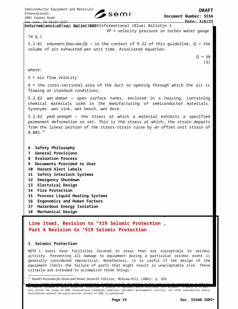
19 Seismic Protection108: Users have facilities located in areas that are susceptible to seismic activity. Preventing all damage to equipment during a particular seismic event is generally considered impractical. Nonetheless, it is useful if the design of the equipment limits the failure of parts that might result in unacceptable risk. These criteria are intended to accomplish three things:
1. Guide equipment suppliers to identify and correctly design the internal frame and components critical to controlling risk if the equipment is subject to anticipated seismic forces; and
2. Encourage equipment suppliers to provide equipment that end users can return to operation as soon as practical after a seismic event; and
3. Identify the equipment information needed by users to appropriately secure the equipment within their facility.
The user might may require more stringent design criteria than what is given here because of increased site vulnerability (e.g., local soil conditions and building design may produce significantly higher accelerations), alternate installation scenarios, or local regulatory requirements. Certified drawings and calculations might may be required in some jurisdictions.
19.1 General — The equipment should be designed so that there are no parts anticipated to fail or yield as a result of the seismic forces anticipated to be experienced by the equipment such that there would be a to control the risk of injury to personnel, or adverse environmental impact of Medium or higher per the SEMI S10 . equipment and facility damage due to movement, overturning, or leakage of chemicals (including liquid splashing), during a seismic event. The design should also control equipment damage due to failure of fragile parts (e.g., quartzware, ceramics) during a seismic event.
109: These criteria are intended to accomplish two things:
1. allow equipment suppliers to correctly design the internal frame and components to withstand seismic forces; and
2. allow equipment designers to provide end-users with the information needed to appropriately secure the equipment within their facility.
19.1.1 Because preventing all damage to equipment may be impractical, the design should control the failure of parts that may result in increased hazard (e.g., hazardous materials release, fire, projectile). The determination of such parts should include consideration of potential: equipment movement and overturning, leakage of chemicals (including fluid lines breaking and liquids splashing), failure of fragile parts (e.g., quartzware, ceramics) or cantilevered parts, hazardous materials release, fire, and projectiles.
110: It is recommended that the hazard analysis described in § 6.8 be used to evaluate both the risk of part failure and the effectiveness of control measures
19.1.1.1 These parts should be accessible for evaluation of damage.
19.1.2 Such parts should be accessible for visual evaluation of damage.
111: SEMI S8 contains guidelines for maintainability and serviceability; these may be used to estimate sufficient determine accessibility.
19.1.3 Structurally independent modules are modules which react to seismic forces independently and do not transfer the forces to adjacent modules, and should be assessed independently.
19.1.4 The equipment should be considered in the condition it is anticipated to be in during normal operation.
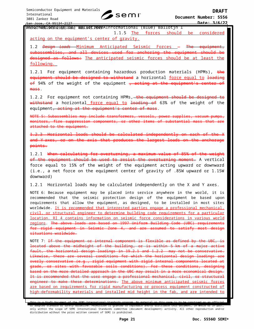
19.1.5 The forces should be considered acting on the equipment’s center of gravity.
19.2 Design Loads Minimum Anticipated Seismic Forces — The equipment, subassemblies, and all devices used for anchoring the equipment should be designed as follows: The anticipated seismic forces should be at least the following.
This is a Draft Document of the SEMI International Standards program. No material on this page is to be construed as an official or adopted Standard or Safety Guideline. Permission is granted to reproduce and/or distribute this document, in whole or in part, only within the scope of SEMI International Standards committee (document development) activity. All other reproduction and/or distribution without the prior written consent of SEMI is prohibited.
Page 14 Doc. 5556 SEMI
Line Item1, Revision to “§19 Seismic Protection”, Part A Revision to “§19 Seismic Protection”
Semiconductor Equipment and Materials International3081 Zanker RoadSan Jose, CA 95134-2127Phone: 408.943.6900, Fax: 408.943.7943
DRAFTDocument Number: 5556
Date: 5/8/23
19.2.1 For equipment containing hazardous production materials (HPMs), the equipment should be designed to withstand a horizontal force equal to loading of 94% of the weight of the equipment , acting at the equipment’s center of mass.
19.2.2 For equipment not containing HPMs, the equipment should be designed to withstand a horizontal force equal to loading of 63% of the weight of the equipment, acting at the equipment’s center of mass.
112: Subassemblies may include transformers, vessels, power supplies, vacuum pumps, monitors, fire suppression components, or other items of substantial mass that are attached to the equipment.
19.2.3 Horizontal loads should be calculated independently on each of the X and Y axes, or on the axis that produces the largest loads on the anchorage points.
19.2.3 When calculating for overturning, a maximum value of 85% of the weight of the equipment should be used to resist the overturning moment. A vertical force equal to 15% of the weight of the equipment acting upward or downward (i.e., a net force on the equipment center of gravity of .85W upward or 1.15W downward)
19.2.4 Horizontal loads may be calculated independently on the X and Y axes.
113: Because equipment may be placed into service anywhere in the world, it is recommended that the seismic protection design of the equipment be based upon requirements that allow the equipment, as designed, to be installed in most sites worldwide. It is recommended that interested parties engage a professional mechanical, civil, or structural engineer to determine building code requirements for a particular location. RI 4 contains information on seismic force considerations in various world regions . The above loads are based on 1997 Uniform Building Code (UBC) requirements for rigid equipment in Seismic Zone 4, and are assumed to satisfy most design situations worldwide.
114: If the equipment or internal component is flexible as defined by the UBC, is located above the midheight of the building, or is within 5 km of a major active fault, the horizontal design loadings in 19.2.1 and 19.2.2 may not be conservative. Likewise, there are several conditions for which the horizontal design loadings are overly conservative (e.g., rigid equipment with rigid internal components located at grade, or sites with favorable soils conditions). For these conditions, designing based on the more detailed approach in the UBC may result in a more economical design. It is recommended that the user engage a professional mechanical, civil, or structural engineer to make these determinations. The above minimum anticipated seismic forces are based on requirements for rigid manufacturing or process equipment constructed of high-deformability materials and installed mid height in the fab, and are intended to be sufficient for the basic safety goals of SEMI S2 .
The supplier should provide the following data and procedures to the user. This information should be included in the installation instructions as part of the documentation covered in § 9.
A drawing of the equipment, its support equipment, its connections (e.g., ventilation, water, vacuum, gases) and the anchorage locations identified in § 19.3 .
The type of feet used and their location on a base frame plan drawing.
The weight distribution on each foot.
Physical dimensions, including width, length, and height of each structurally independent module.
Weight and location of the center of mass for each structurally independent module.
Acceptable locations on the equipment frame for anchorage.
115: A “structurally independent module” reacts to seismic loads by transferring substantially all of the loads to its own anchorages, as opposed to transferring the loads to adjacent modules.
19.3 The locations of the tie-ins, attachments, or seismic anchorage points intended by the supplier to help limit equipment motion during a seismic event should be clearly identified by direct labelling or in the documentation provided to the user.
116: It is not the intent of SEMI S2 that the supplier provide the seismic attachment point hardware. Such hardware may be provided as agreed upon between supplier and user.
117: It is assumed that the responsibility of the user will determine whether to verify that the vibration isolation, leveling, seismic reinforcing, and load distribution is are adequate for their particular building requirements, and if not, negotiate changes to the equipment as needed, and as agreed upon between the supplier and user.
This is a Draft Document of the SEMI International Standards program. No material on this page is to be construed as an official or adopted Standard or Safety Guideline. Permission is granted to reproduce and/or distribute this document, in whole or in part, only within the scope of SEMI International Standards committee (document development) activity. All other reproduction and/or distribution without the prior written consent of SEMI is prohibited.
Page 15 Doc. 5556 SEMI
Semiconductor Equipment and Materials International3081 Zanker RoadSan Jose, CA 95134-2127Phone: 408.943.6900, Fax: 408.943.7943

DRAFTDocument Number: 5556
Date: 5/8/23
20 Automated Material Handlers
21 Environmental Considerations
22 Exhaust Ventilation
23 Chemicals
24 Ionizing Radiation
25 Non-Ionizing Radiation and Fields
26 Lasers
27 Sound Pressure Level
28 Related Documents
APPENDIX 1
APPENDIX 2
APPENDIX 3
APPENDIX 4
APPENDIX 5
RELATED INFORMATION INDEX
RELATED INFORMATION 1
RELATED INFORMATION 2
RELATED INFORMATION 3
This is a Draft Document of the SEMI International Standards program. No material on this page is to be construed as an official or adopted Standard or Safety Guideline. Permission is granted to reproduce and/or distribute this document, in whole or in part, only within the scope of SEMI International Standards committee (document development) activity. All other reproduction and/or distribution without the prior written consent of SEMI is prohibited.
Page 16 Doc. 5556 SEMI
Semiconductor Equipment and Materials International3081 Zanker RoadSan Jose, CA 95134-2127Phone: 408.943.6900, Fax: 408.943.7943
DRAFTDocument Number: 5556
Date: 5/8/23
RELATED INFORMATION 4 SEISMIC PROTECTIONNOTICE: This Related Information is not an official part of SEMI S2 and was derived from the work of the global Environmental Health & Safety Technical Committee. This Related Information was approved for publication by full letter ballot procedures on October 21, 1999.
R4-1 Seismic Protection Checklist
Supporting Review Criteria for Seismic Protection of Related Components
If the answer to Questions A.1 or A.2 is “No,” or the answer to any other of these questions in the checklist is “Yes,” then a detailed analysis may need to be performed by a structural or mechanical engineer.A. Equipment Anchorage1. Have lateral force and overturning calculations been performed (see example)?
Yes No Comments:
2. Are all modules fastened at a minimum of four points and can the fasteners support the forces identified in question 1 above? Yes No Comments:
3. Is it possible that there could be excessive seismic anchor movements that could result in relative displacements between points of support or attachment of the components (e.g., between vessels, pipe supports, main headers, etc.)? Yes No Comments:
4. Is there inadequate horizontal support? Yes No Comments:
5. Is there inadequate vertical supports and/or insufficient lateral restraints? Yes No Comments:
6. Are support fasteners inappropriately secured? Yes No Comments:
7. Is there inadequate anchorage of attached equipment? Yes No Comments:
1: One way of judging whether supports, fasteners, or anchorages are “inadequate” or inappropriately secured” is to determine whether their stress levels under seismic loading stay below the allowable stress levels set by building code. Such allowable stress levels are typically a fraction <1 of the yield strength.
B. Equipment Assembly, Installation and Operation1. Are the materials of construction of the components susceptible to seismic damage?
Yes No Comments:
2. Are there significant cyclic operational loading conditions that may substantially reduce system fatigue life? Yes No Comments:
3. Are there any threaded connections, flange joints, or special fittings? Yes No Comments:
4. If answer to Question 4 is “Yes,” are these connections, joints, or special fittings in high stress locations? Yes No Comments:
This is a Draft Document of the SEMI International Standards program. No material on this page is to be construed as an official or adopted Standard or Safety Guideline. Permission is granted to reproduce and/or distribute this document, in whole or in part, only within the scope of SEMI International Standards committee (document development) activity. All other reproduction and/or distribution without the prior written consent of SEMI is prohibited.
Page 17 Doc. 5556 SEMI
Semiconductor Equipment and Materials International3081 Zanker RoadSan Jose, CA 95134-2127Phone: 408.943.6900, Fax: 408.943.7943

DRAFTDocument Number: 5556
Date: 5/8/23
5. Are there short or rigid spans that cannot accommodate the relative displacement of the supports (e.g.,piping spanning between two structural systems)? Is hazardous gas piping provided with a “pigtail” (i.e., spiral) or bent 3 times (z, y, and z direction) to absorb 3-dimensional displacements? Yes No Comments:
6. Are there large, unsupported masses (e.g., valves) attached to components? Yes No Comments:
7. Are there any welded attachments to thin wall components? Yes No Comments:
8. Could any sensitive equipment (e.g., control valves) be affected? Yes No Comments:
C. Seismic Interactions1. Are there any points where seismically induced interaction with other elements, structures, systems, or
components could damage the components (e.g., impact, falling objects, etc.)? Yes No Comments:
2. Could there be displacements from inertial effects? Yes No Comments:
R4-2 Derivation of § 19, Seismic Load GuidelinesR4-2.1 The horizontal loadings of 94% and 63%, found in § 19.2.1 and § 19.2.2 , were based on following assumptions for factors in formula 32-2 in § 1632.2 of the 1997 Uniform Building Code (UBC):
Ap = 1.0 (i.e., treat the equipment as a rigid structure) Ca = 0.44(1.2) (i.e., seismic zone 4, soil profile type SD, and site 5 km from a seismic source type A) Ip = 1.0 and 1.5 for non-HPM and HPM equipment, respectively hx/hr = 0.5 (i.e., equipment attached at point halfway between grade elevation and roof elevation) Rp = 1.5 (i.e., shallow anchor bolts).
Starting with equation 32-2, letting Ip = 1.5, and substituting the above values:
Fp (ultimate) = [(1.0 × 0.44(1.2) × 1.5)/1.5] [1 + 3(0.5)] Wp
= [0.44(1.2)] [1 + 1.5] Wp
= [0.528] [2.5] Wp
= [1.32] Wp
2: This number is now adjusted from ultimate strength loading to yield strength loading by dividing by 1.4:
Fp (yield) = Fp (ultimate)/1.4= [1.32]/1.4 Wp
= [0.94] Wp
And for Ip = 1.0,
Fp (yield) = [.94] [ 1.0/1.5] Wp
= [.63] Wp
Notes re-selection of ap value of 1.0:
This is a Draft Document of the SEMI International Standards program. No material on this page is to be construed as an official or adopted Standard or Safety Guideline. Permission is granted to reproduce and/or distribute this document, in whole or in part, only within the scope of SEMI International Standards committee (document development) activity. All other reproduction and/or distribution without the prior written consent of SEMI is prohibited.
Page 18 Doc. 5556 SEMI
Line Item1, Revision to “§19 Seismic Protection”, Part B Revision to “Related Information 4 Seismic Protection”
Semiconductor Equipment and Materials International3081 Zanker RoadSan Jose, CA 95134-2127Phone: 408.943.6900, Fax: 408.943.7943
DRAFTDocument Number: 5556
Date: 5/8/23
Table 16-O of 1997 UBC, line 3.C., was interpreted to read: “Any flexible equipment...” in structural terms, the structure of typical semiconductor equipment is considered “rigid.”
R4-2.2 Assumptions Used for Above Derivation
R4-2.2.1 Because typical semiconductor equipment is considered rigid, a frequency response analysis was not considered to be necessary.
R4-2.2.2 Seismic waves typically have vertical as well as horizontal components associated with them; however, these components typically arrive out of phase (i.e., they do not reach maximum values simultaneously). The vertical component serves to, in effect, reduce the amount of equipment mass that is available to resist overturning or toppling. The task force chose to take this into account by limiting the calculated weight available to resist overturning to 85% of the weight of the equipment. An alternate method, not chosen by the task force, could have been to simultaneously apply a vertical (Z) force.
R4-3 Example of seismic design load based on standards/Codes applicable for known semiconductor manufacturing locationR4-3.1 United States
R4-3.1.1 The horizontal seismic loadings are based on following assumptions for factors (Equation 13.3-1, 13.3-2, and 13.3-3 in § 13.3.1) in ASCE7-10:
FP=0.4 ∙ aP ∙ SDS ∙W P
( RP
I P)
(1+2 zh ) R4-3.2-1
Fp is not required to be taken as greater than:
FP=1.6∙ SDS∙ I P ∙W P R4-3.2-2
and Fp should not be taken as less than:
FP=0.3∙ SDS ∙ I P ∙W P R4-3.2-3
Fp: seismic design force
SDS: design, 5 percent damped, spectral response acceleration parameter at short periods as defined in §11.4.4 of ASCE7-10
where:
ap: component amplification factor RP : component response modification factor
Ip: component importance factor
WP: component operating weight
z = Height in structure at point of attachment of component with respect to the base.
h = Average roof height of structure with respect to the base.
R4-3.1.2 Assumptions Used for Above Derivation
R4-3.1.3 Generally equipment is considered rigid. In this case a frequency response analysis is not necessary.
R4-3.1.4 Generally equipment does not use vibration isolation. In case of the component supported by vibration isolators, the value of ap should be changed to 2.5 in Equation R4-3.2-1, Equation R4-3.2-2 and Equation R4-3.2-3 and should calculate the Fp for the each case.
R4-3.1.5 Vertical Seismic Load — Based on § 13.3.1 in ASCE7-10, the nonstructural component should be designed for a concurrent force ±0.2SDSWP.
This is a Draft Document of the SEMI International Standards program. No material on this page is to be construed as an official or adopted Standard or Safety Guideline. Permission is granted to reproduce and/or distribute this document, in whole or in part, only within the scope of SEMI International Standards committee (document development) activity. All other reproduction and/or distribution without the prior written consent of SEMI is prohibited.
Page 19 Doc. 5556 SEMI
Semiconductor Equipment and Materials International3081 Zanker RoadSan Jose, CA 95134-2127Phone: 408.943.6900, Fax: 408.943.7943

DRAFTDocument Number: 5556
Date: 5/8/23
FPV=±0.2 ∙ SDS ∙W P R4-3.2-4
R4-3.2 Taiwan
R4-3.2.1 The horizontal seismic loadings are based on following assumptions for factors.
FP=0.4 ∙ a p ∙ I p ∙ SDS ∙W P
Rp(1+2
hx
hn) R4-3.
2-5
Fp is not required to be taken as greater than:
FP=1.6∙ SDS∙ I P ∙W P R4-3.2- 6
and Fp should not be taken as less than:
FP=0.3∙ SDS∙ I P ∙W P R4-3.2-7
Fp: seismic design force
SDS: design, 5 percent damped, spectral response acceleration parameter at short periods
where:
ap: component amplification factor
Rpa : Allowable seismic response modification factor
Rp: Component amplification factor defined in Table 4-1 12 .(Other rigid equipment)
Ip: component importance factor
WP: component operating weight
hx /hn; Height of the structure in the fixed point of the components
Minimum seismic force for horizontal design
F ph=0.4 ∙ SDS ∙ I p ∙ap
Rpa∙(1+2 hx/hn) ∙W p R4-3.2-8
R4-3.2.2 Vertical Seismic Load — Based on TBC
F pv=12⋅F ph=0.50 W p
R4-3.2-9
R4-3.2.3 Minimum seismic force for vertical design: Near-fault region
R4-3.2.4 F pv=
23⋅F ph =0 .60W p
R4-3.2-10Where, Fph is the horizontal design force, which is the same as Fp used in TBC
R4-3.3 Japan In Japan, there are several guidelines for non-structural elements or building equipment. “Seismic Design and Construction Guideline for Building Equipment” published by Building Center of Japan (BCJ) were conformed to The Building Standard Law of Japan and have been adopted as a jurisdictional requirement to the building constructions. Appropriateness of the criteria in the guideline has been verified in several large earthquakes over 6 Lower of the JMA Seismic Intensity in Japan (http://www.jma.go.jp/jma/kishou/know/shindo/explane.html). In the guideline mentioned above, the basic seismic coefficient for equipment is 0.4 and the values of design horizontal seismic coefficient are 0.4, 0.6, 1.0, 1.5 and 2.0. If designers practice dynamic analysis or other detail calculation
This is a Draft Document of the SEMI International Standards program. No material on this page is to be construed as an official or adopted Standard or Safety Guideline. Permission is granted to reproduce and/or distribute this document, in whole or in part, only within the scope of SEMI International Standards committee (document development) activity. All other reproduction and/or distribution without the prior written consent of SEMI is prohibited.
Page 20 Doc. 5556 SEMI
Semiconductor Equipment and Materials International3081 Zanker RoadSan Jose, CA 95134-2127Phone: 408.943.6900, Fax: 408.943.7943
DRAFTDocument Number: 5556
Date: 5/8/23
methods to determine the design horizontal seismic coefficient, values should be rounded and classified to the five values mentioned above. In this guideline, the vertical loading is set to be 50% of horizontal loading.
Design Horizontal Seismic Coefficient Ks
Classification of applied floorSeismic Resistant Class S
Seismic ResistantClass A
Seismic ResistantClass B
Upper Floors 、 Roof or Penthouse
2.0 1.5 1.0
Middle Floors 1.5 1.0 0.6
Basement or First Floor 1.0(1.5) 0.6(1.0) 0.4(0.6)
The values within parentheses shall be applied to water tanks installed on the basement, on the first floor or on the ground.Definition of upper floors:・ The top floor of two to six-story buildings shall be the upper floor. ・ The top floor and the next to the top floor of seven- to nine-story buildings shall be the upper floors. The rest is omitted.Definition of middle floors:・ The floors except basement, first floor or upper floors shall be the middle floors. Note: Application of each seismic resistant class.1. Seismic resistant class shall be applied to the equipment, considering its response amplification factor.
(Example: Components on vibration isolation devices shall be applied the seismic resistant class A or S.)
2. Seismic resistant class shall be applied to the building or equipment, considering their functions during or after severe earthquakes (e.g., disaster prevention center or important water tank)
The rest is omitted.
R4-3.4 Europe
3: It was intention of Japan Seismic protection TF to include values of seismic protection design load and supporting formula that are applicable in Europe. As the TF was unable to identify the adequate reference to fulfill its intention at the time of preparation of this revision of S2, the information is not provided in this revision. It is expectation of the TF to add the information in future revision.
R4-4 Source for Examples of Seismic Anchorage DetailsR4-4.1 Detailed illustrations of examples of seismic anchorage details were developed by Working Group #9 of the Japan 300 mm (“J300”) effort, and were printed in their Report No. 9 in the 2nd Lecture, ICs Factory Design for 300 mm Wafer Line Standardizing Study, December, 1996.
This is a Draft Document of the SEMI International Standards program. No material on this page is to be construed as an official or adopted Standard or Safety Guideline. Permission is granted to reproduce and/or distribute this document, in whole or in part, only within the scope of SEMI International Standards committee (document development) activity. All other reproduction and/or distribution without the prior written consent of SEMI is prohibited.
Page 21 Doc. 5556 SEMI
Penthouse
Upper Floors
Middle Floors
First Floor
Basement
Semiconductor Equipment and Materials International3081 Zanker RoadSan Jose, CA 95134-2127Phone: 408.943.6900, Fax: 408.943.7943

DRAFTDocument Number: 5556
Date: 5/8/23
R4-4.2 Design Example (refer to Figure R4-1 for illustration of example)
R4-4.2.1 Disclaimer: the calculations below are not a complete seismic analysis. A complete analysis might also include such things as: stress distribution through a multiple-fastener connection; prying action; bearing stress; simultaneous combined stresses on the fasteners; and a review of weld geometry. A complete seismic analysis should be done by a qualified engineer.
R4-4.1 Design Example (refer to Figure R4-1 for illustration of example)
Disclaimer: the calculations below are not a complete seismic analysis. A complete analysis might also include such things as: stress distribution through a multiple-fastener connection; prying action; bearing stress; simultaneous combined stresses on the fasteners; and a review of weld geometry. A complete seismic analysis should be done by a qualified engineer. R4-1 Source for Examples of Seismic Anchorage Details
R4-4.2 Design Example (refer to Figure R4-1 、R4-2 for illustration of example)
G: Center of Gravity
Wp: Weight of equipment ( kN)
This is a Draft Document of the SEMI International Standards program. No material on this page is to be construed as an official or adopted Standard or Safety Guideline. Permission is granted to reproduce and/or distribute this document, in whole or in part, only within the scope of SEMI International Standards committee (document development) activity. All other reproduction and/or distribution without the prior written consent of SEMI is prohibited.
Page 22 Doc. 5556 SEMI
I
Fs(Lateral Force)
Anchor
(Wp- Fpv)
Operating weight of Equipment (WP)
Rb(Tensile Stress)
hG
Fpv
l
lG
Fph
G
WP
Figure R4-1
Figure R4-2
Semiconductor Equipment and Materials International3081 Zanker RoadSan Jose, CA 95134-2127Phone: 408.943.6900, Fax: 408.943.7943

DRAFTDocument Number: 5556
Date: 5/8/23
Rb: Force per anchor bolt ( kN)
n : Total number of anchor bolts
nt: The total number of anchor bolts on the side that is pulled when considering the equipment overturning.
hG: The height of the center of gravity from installation surface of the equipment
l: The bolt span, looking from the side under investigation. (m)
lG: The distance from the bolt to the equipment center of gravity, looking from the side under investigation
( However l G≦ 1/2 ) (m)
Fph: Horizontal design seismic force ( kN)
Fpv: Vertical design seismic force ( kN)
R4-5 Calculation of Overturning ForceR4-5.1 Vertical seismic force is refereed by R4-3.3 F pv=0.15 WP
R4-5.2 The force required to pull out an anchor bolt is shown below
Rb={Fph ∙ hG−(W p−Fpv ) ∙lG }
l ∙n t
For HPM Equipment,
F ph=0.94 W p
Rb={0.94 W p ∙ hG−(W p−0.15 W p ) ∙ lG}
l ∙ nt
Rb=(0.94 W p ∙hG−0.85 ∙ W p ∙lG )
l ∙ nt
Rb=W p (0.94 hG−0.85lG )
l ∙ nt
When Rb≧ 0 the equipment may overturn When there is a possibility of the equipment overturning, overturning prevention fittings are required
When Rb < 0 the equipment will not overturn
R4-6 Calculation of Lateral ForceR4-6.1 Fs is the shear force on one bolt when a left-right horizontal load is applied
F s=F ph/n
R4-6.2 The lateral force acts as shear on the floor anchor fasteners and shear or tensile loading on the equipment anchor fasteners depending upon orientation. The actual reactions of the fasteners should be calculated by a qualified engineer.
This is a Draft Document of the SEMI International Standards program. No material on this page is to be construed as an official or adopted Standard or Safety Guideline. Permission is granted to reproduce and/or distribute this document, in whole or in part, only within the scope of SEMI International Standards committee (document development) activity. All other reproduction and/or distribution without the prior written consent of SEMI is prohibited.
Page 23 Doc. 5556 SEMI
Semiconductor Equipment and Materials International3081 Zanker RoadSan Jose, CA 95134-2127Phone: 408.943.6900, Fax: 408.943.7943

DRAFTDocument Number: 5556
Date: 5/8/23
R4-6 Calculation of Lateral ForceR4-6.1 Lateral force on each leg is equal to FP/# of legs = FP/4
R4-6.2 The lateral force acts as shear on the floor anchor fasteners and shear or tensile loading on the equipment anchor fasteners depending upon orientation. The actual reactions of the fasteners should be calculated by a qualified engineer.
Figure R4-1
Design Example
R4-7 Calculation of Overturning ForceR4-7.1 Sum the moments of the reactions on the system about line through the legs A and B:
This is a Draft Document of the SEMI International Standards program. No material on this page is to be construed as an official or adopted Standard or Safety Guideline. Permission is granted to reproduce and/or distribute this document, in whole or in part, only within the scope of SEMI International Standards committee (document development) activity. All other reproduction and/or distribution without the prior written consent of SEMI is prohibited.
Page 24 Doc. 5556 SEMI
Semiconductor Equipment and Materials International3081 Zanker RoadSan Jose, CA 95134-2127Phone: 408.943.6900, Fax: 408.943.7943

DRAFTDocument Number: 5556
Date: 5/8/23
(CW =+) MAB= 0 = FP (h) – 0.85WP(L2) –2R(L1 )= 0 (R4-1)
FP (h) – 0.85WP(L2) R = _________________ (R4-2)
2L1
FP = 0.94WP
WP (0.94h – 0.85L2) R = _________________ (R4-3)
2L1
If 0.94h 0.85L2, then there is a tension reaction, R, at the two anchors, to resist overturning of system.
Example:
L1 = 50 inch
L2 = 20 inch
h = 36
W = 5000 lbs
Lateral force = Fp/4 = 0.94(5000)/4 = 1175
WP (0.94h – 0.85L2) Overturning force = R =_________________ (R4-4)
2L1
= 5000 (0.94(36) – 0.85(20))_____________________ (R4-5)
2(50)
R = 842 lbs
RELATED INFORMATION 5RELATED INFORMATION 6RELATED INFORMATION 7RELATED INFORMATION 8RELATED INFORMATION 9RELATED INFORMATION 10RELATED INFORMATION 11RELATED INFORMATION 12RELATED INFORMATION 13RELATED INFORMATION 14
This is a Draft Document of the SEMI International Standards program. No material on this page is to be construed as an official or adopted Standard or Safety Guideline. Permission is granted to reproduce and/or distribute this document, in whole or in part, only within the scope of SEMI International Standards committee (document development) activity. All other reproduction and/or distribution without the prior written consent of SEMI is prohibited.
Page 25 Doc. 5556 SEMI
Semiconductor Equipment and Materials International3081 Zanker RoadSan Jose, CA 95134-2127Phone: 408.943.6900, Fax: 408.943.7943

DRAFTDocument Number: 5556
Date: 5/8/23
RELATED INFORMATION 15RELATED INFORMATION 16DELAYED REVISION 1DELAYED REVISION 2
This is a Draft Document of the SEMI International Standards program. No material on this page is to be construed as an official or adopted Standard or Safety Guideline. Permission is granted to reproduce and/or distribute this document, in whole or in part, only within the scope of SEMI International Standards committee (document development) activity. All other reproduction and/or distribution without the prior written consent of SEMI is prohibited.
Page 26 Doc. 5556 SEMI
Semiconductor Equipment and Materials International3081 Zanker RoadSan Jose, CA 95134-2127Phone: 408.943.6900, Fax: 408.943.7943