Embed Size (px)
Citation preview
Observatory Automation ProjectD il d D i R iDetailed Design Review
Electric Dome Drive Systemy(EDDS)
Steven BaumanContributors: Sarah Gajadhar, Grant Matsushige, Ivan Look Derrick Salmon Ralph Taroma LarryIvan Look, Derrick Salmon, Ralph Taroma, Larry Roberts, Casey Elizares, Tyson Arruda, William Cruise, Tom Vermeulen, Jim Thomas, DeeDee
Warren, Karun ThanjavurWarren, Karun Thanjavur
Version 1.1 July 9, 2010
Appendix T OAP Dome Drive DDR Presentation
T1

Appendix T OAP Dome Drive DDR Presentation
T2

ScopeScope
Design solution to replace the hydraulic power unit and operate the dome drive system with electronically controlled motor units.Remotely control the system under the guidelines provided by the OAP projectM h ifi i d i f d Meets the specifications and requirements formed for the dome drive electrical upgrade. D t il d d i h t th i ti t Detailed design changes to the existing system, mechanical interfaces, safety considerations, anticipated costs and estimated manpower anticipated costs and estimated manpower resources.
Appendix T OAP Dome Drive DDR Presentation
T3

HydraulicHydraulicHydraulic Hydraulic power unitpower unit
Appendix T OAP Dome Drive DDR Presentation
T4
ScopeScope
Design solution to replace the hydraulic power unit and operate the dome drive system with electronically controlled motor units.Remotely control the system under the guidelines provided by the OAP projectM h ifi i d i f d Meets the specifications and requirements formed for the dome drive electrical upgrade. D t il d d i h t th i ti t Detailed design changes to the existing system, mechanical interfaces, safety considerations, anticipated costs and estimated manpower anticipated costs and estimated manpower resources.
Appendix T OAP Dome Drive DDR Presentation
T5
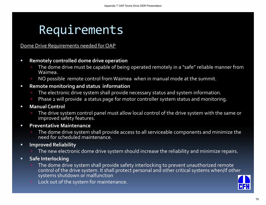
RequirementsDome Drive Requirements needed for OAP
Remotely controlled dome drive operation The dome drive must be capable of being operated remotely in a “safe” reliable manner from Waimea.NO possible remote control from Waimea when in manual mode at the summit.
Remote monitoring and status informationThe electronic drive system shall provide necessary status and system information.Phase 2 will provide a status page for motor controller system status and monitoring.
Manual Control The drive system control panel must allow local control of the drive system with the same or y p yimproved safety features.
Preventative Maintenance The dome drive system shall provide access to all serviceable components and minimize the need for scheduled maintenance.
Improved Reliability The new electronic dome drive system should increase the reliability and minimize repairs.
Safe Interlocking The dome drive system shall provide safety interlocking to prevent unauthorized remote y p y g pcontrol of the drive system. It shall protect personal and other critical systems when/if other systems shutdown or malfunctionLock out of the system for maintenance.
Appendix T OAP Dome Drive DDR Presentation
T6

•Modify 5th floor spacer room to allow for more space around the p
motor.•Alterations will improve
maintenance and repairs in themaintenance and repairs in the future.
Appendix T OAP Dome Drive DDR Presentation
T7

Replacement Actuator
Parker Hannifin
Pneumatic actuatoractuator122psi
operating pressure
Appendix T OAP Dome Drive DDR Presentation
T8
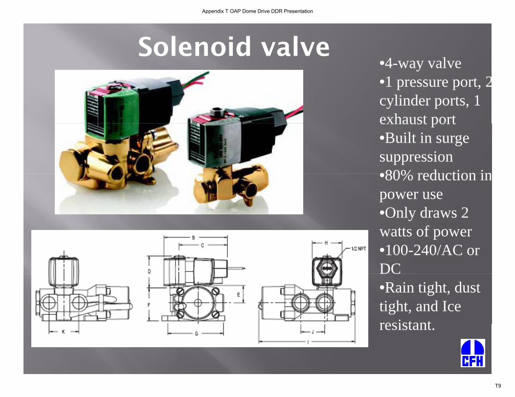
Solenoid valve•4-way valve•1 pressure port, 2cylinder ports, 1 exhaust portexhaust port•Built in surge suppression•80% reduction in•80% reduction inpower use•Only draws 2 watts of power•100-240/AC or DCDC•Rain tight, dust tight, and Ice resistantresistant.
Appendix T OAP Dome Drive DDR Presentation
T9

Proof of concept
The Daycrew assembled andassembled and bench tested a
similar two port actuator and solenoid valve withvalve with
122psi operating p g
pressure to verify and
validate thevalidate the design idea.
Appendix T OAP Dome Drive DDR Presentation
T10

Appendix T OAP Dome Drive DDR Presentation
T11

Dome Drive Unit Components
Brevini Gear d i b
SHP Main shaft assembly
SHP wheel assembly
reduction box assembly
Hydroland Hydraulic motor
Appendix T OAP Dome Drive DDR Presentation
T12

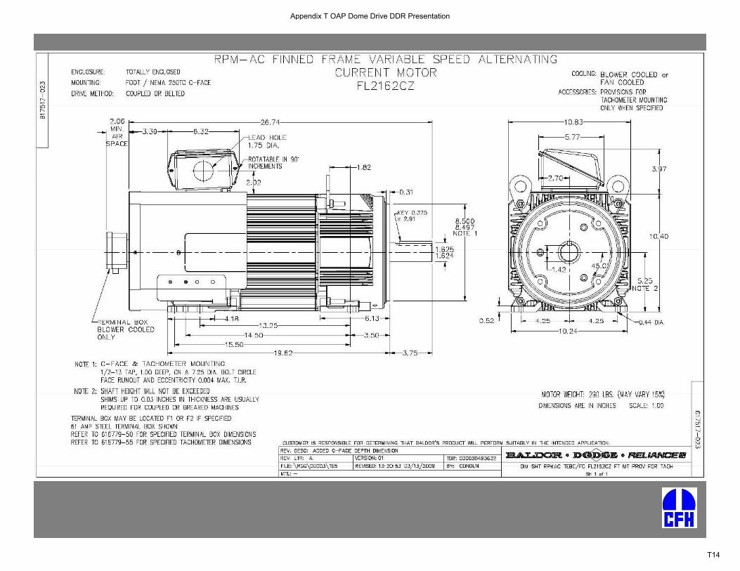
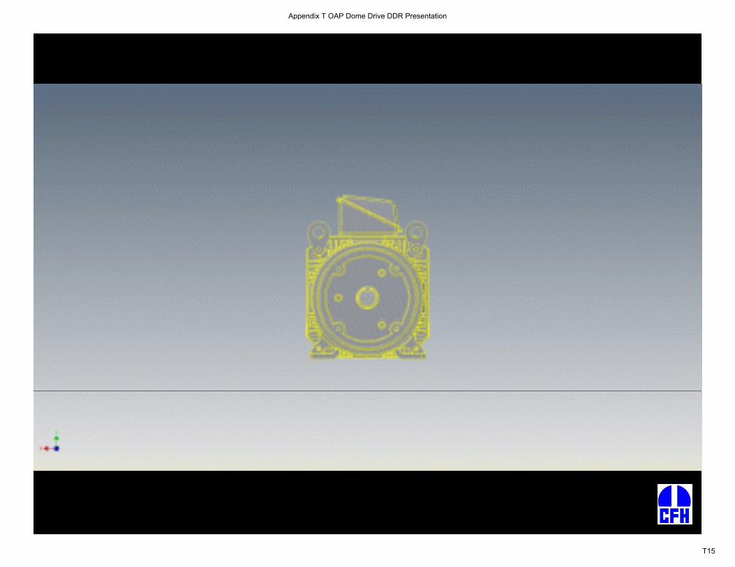
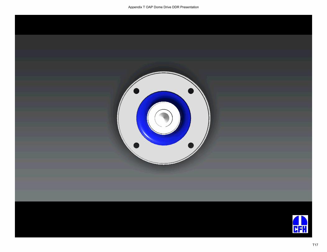
New Motors and AdapterBaldor RPM AC 20HP
Exploded adapter kit view
20HP motor
1750RPM3PH360HZ
BreviniNema250TC Motor adapter flflange
Appendix T OAP Dome Drive DDR Presentation
T13
Appendix T OAP Dome Drive DDR Presentation
T14
Appendix T OAP Dome Drive DDR Presentation
T15

Appendix T OAP Dome Drive DDR Presentation
T16
Appendix T OAP Dome Drive DDR Presentation
T17
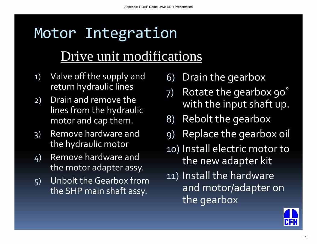
Motor Integration
1) Valve off the supply and 6) Drain the gearbox
Drive unit modifications1) Valve off the supply and
return hydraulic lines2) Drain and remove the
l f h h d l
6) Drain the gearbox7) Rotate the gearbox 90˚
with the input shaft up.lines from the hydraulic motor and cap them.
3) Remove hardware and
with the input shaft up.8) Rebolt the gearbox9) Replace the gearbox oil3)
the hydraulic motor4) Remove hardware and
the motor adapter assy
9) p g10) Install electric motor to
the new adapter kitthe motor adapter assy.
5) Unbolt the Gearbox from the SHP main shaft assy.
11) Install the hardware and motor/adapter on the gearboxthe gearbox
Appendix T OAP Dome Drive DDR Presentation
T18

Appendix T OAP Dome Drive DDR Presentation
T19

Appendix T OAP Dome Drive DDR Presentation
T20

Location of Dome Drive cabinetCabinet details•Nema 1 enclosure with fans and filters.S lf t di bi t ith l•Self standing cabinet with legs
or other means of support.•Wheels or casters incorporated for transportation.p•Cabinet fitted with Main molded case circuit breaker (MCB) door and or side panel disconnectdisconnect.•The cabinet will be located in front of the wall, the ladders will be relocated.
Appendix T OAP Dome Drive DDR Presentation
T21
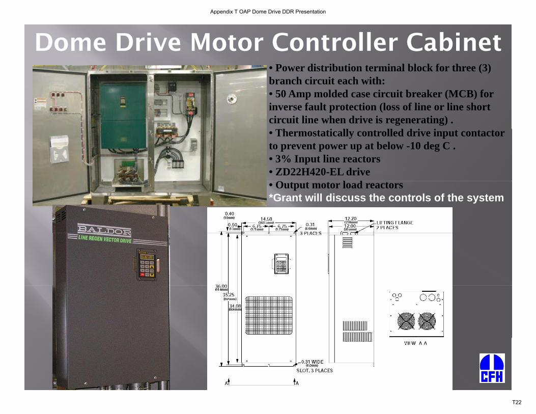
Dome Drive Motor Controller Cabinet • Power distribution terminal block for three (3) branch circuit each with: • 50 Amp molded case circuit breaker (MCB) for inverse fault protection (loss of line or line short circuit line when drive is regenerating) .• Thermostatically controlled drive input contactor to prevent power up at below -10 deg C .• 3% Input line reactors • ZD22H420-EL drive
O• Output motor load reactors*Grant will discuss the controls of the system
Appendix T OAP Dome Drive DDR Presentation
T22

Heat Mitigation strategyHeat dissipation estimates
BHeat dissipation estimates
Motors At Full Speed (3.4HP @ 60˚/min) ~ 95 WattsMeets requirement criteria, no requirement for iti timitigation
Motor Controllers At Full Speed (3.4HP @ 60˚/min) ~ 256 Watts
W i diffi l i d Worst case estimate, difficult to estimate due to intermittent operation
__________________________PLAN__________________A) V t th t t ll h t i t th i it ’ C• A) Vent the motor controller heat into the visitor’s gallery. Sealed room with no other heat sources.
• B) Add a standard ventilation fan above the visitors t i d t t th i l i t th
C
staircase door to vent the room air volume into the staircase
• C) Add a small Thermatron or Lytron heat exchanger i th b ildi l l t t th b tt f th using the building glycol system to the bottom of the
Baldor cabinet.
Appendix T OAP Dome Drive DDR Presentation
T23

Monitoring and Status InformationPhase 2 Motor Controller
Stores data about the Example status page for monitoring the system Stores data about the functionality and health of the drive system
Th O t t b
g g
The Outputs can be monitored such as; speed, torque, voltage, current, etc.
Communication Method
Serial interface communication (RS232) expansion board(RS232) expansion boardFeedback information for status via and RS232 cable and Pearle devicedevice.
Appendix T OAP Dome Drive DDR Presentation
T24

Time and resource estimates – Implementation plan
Award P.O. for Prepare the visitor’s gallery, relocate the
Finalize pneumatic lines and location of the
Baldor Cabinet Build Room Modifications Actuator Integration and Test
Baldor package
Date: ~7/16/2010
ladders, terminate wiring
Date: ~8/5/2010
solenoid valve. Modify the rod clevis brackets
Date: ~7/28/2010
Baldor begin design and assembly of
cabinet
Develop and/or Install provisions for lifting the gear reduction
Shut off supply and return lines, remove old actuator, modify as needed install newcabinet
Date: ~7/19/2010box and motor
Date: ~8/12/2010
needed install new actuator
Date: ~8/4/2010
Review cabinet design, approve for final build and ship
Remove the door casting and/or walls and modify as needed
Test actuator function, run dome with new actuator, install
remaining actuators
Date: ~9‐1‐2010 Date: ~8/19/2010 Date: ~8/26/10
*Some tasks can be preformed in parallel.*
Appendix T OAP Dome Drive DDR Presentation
T25

Time and resource estimates – Implementation plan
Receive motor and adapter inspect
Modify the PLC panel, cabling from PLC to
Receive Baldor drive unit, transport to
Spare motor testing Spare motor controller testing Drive unit integration
adapter, inspect and verify part
Date: ~7/21/2010
cabling from PLC to cabinet location
Date: ~8/31/2010
psummit, move to 5th
floor.
Date: ~9/7/2010
Remove spare drive unit from crate and install on stand
Testing of the PLC controls, air actuator, motor bench testing
Install the cabinet, connect power, motor wiring PLC wiring etcinstall on stand
Date: ~7/21/2010
motor bench testing.
Date: ~9/3/2010
wiring, PLC wiring, etc.
Date: ~9/14/2010
Remove old hydraulic motor and install new
electric motor
Baldor consultant arrives, Integrate first unit with new drive
components, test systemDate: ~7/29/2010 Date: ~9/27 to 10/1/10
*Some tasks can be preformed in parallel.*
Appendix T OAP Dome Drive DDR Presentation
T26
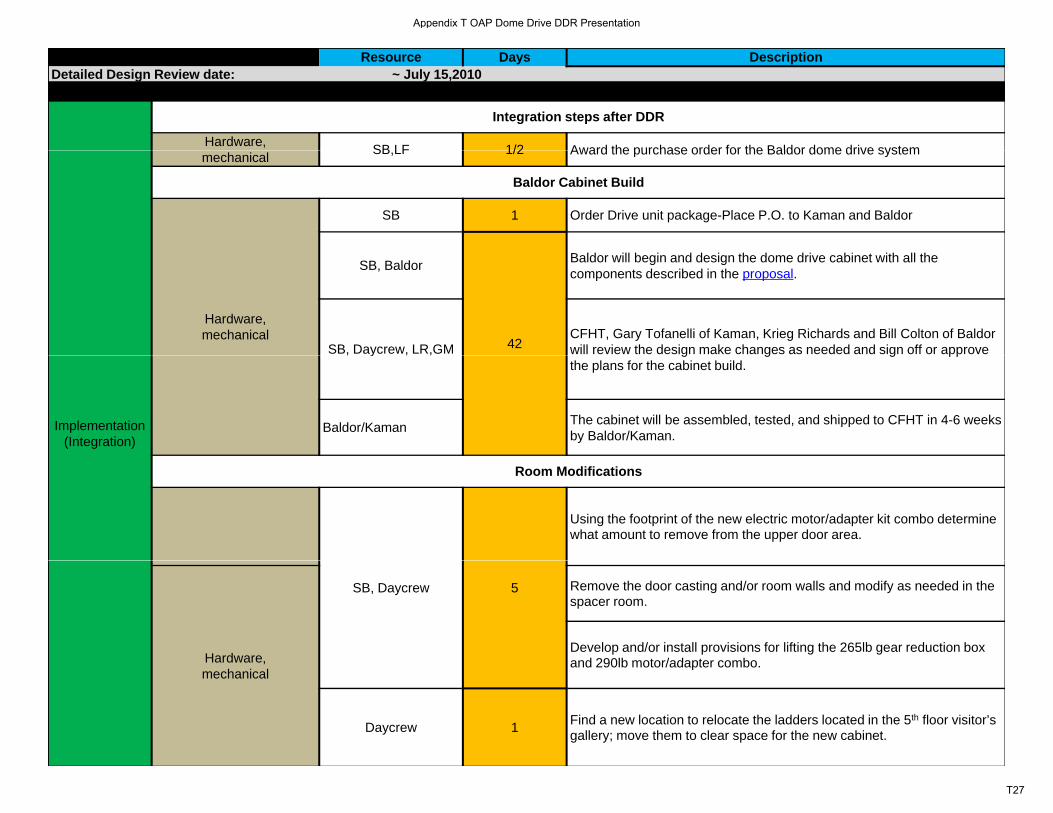
Resource Days DescriptionDetailed Design Review date: ~ July 15,2010
Integration steps after DDR
Hardware, SB LF 1/2 Award the purchase order for the Baldor dome drive systemmechanical SB,LF 1/2 Award the purchase order for the Baldor dome drive system
Baldor Cabinet Build
SB 1 Order Drive unit package-Place P.O. to Kaman and Baldor
B ld ill b i d d i h d d i bi i h ll h
Hardware,mechanical
SB, Baldor
42
Baldor will begin and design the dome drive cabinet with all the components described in the proposal.
SB, Daycrew, LR,GMCFHT, Gary Tofanelli of Kaman, Krieg Richards and Bill Colton of Baldor will review the design make changes as needed and sign off or approve
Implementation(Integration)
, y , , g g g ppthe plans for the cabinet build.
Baldor/Kaman The cabinet will be assembled, tested, and shipped to CFHT in 4-6 weeks by Baldor/Kaman.
Room Modifications
Using the footprint of the new electric motor/adapter kit combo determine what amount to remove from the upper door area.
SB, Daycrew 5
Hardware,
Remove the door casting and/or room walls and modify as needed in the spacer room.
Develop and/or install provisions for lifting the 265lb gear reduction box and 290lb motor/adapter combo,
mechanicaland 290lb motor/adapter combo.
Daycrew 1 Find a new location to relocate the ladders located in the 5th floor visitor’s gallery; move them to clear space for the new cabinet.
Appendix T OAP Dome Drive DDR Presentation
T27

Actuator Integration and Test
1Inspect the actuators, clevis brackets, and pivot pins for correct model # and dimensions
Test set-up for actuators, verify proof of concept on bench
Finalize the pneumatic lines running to each dome drive unit for the actuators
2
Finalize the pneumatic lines running to each dome drive unit for the actuators
Finalize the location of the solenoid valve and plumbing on each dome drive frame
Modify the four (4) female rod clevis brackets
SB, Daycrew, GM
Record the position of the proportioning valve on the supply and return side of the actuator and valve off the actuators, record the turns needed to shut off the flow
Remove the upper and lower pivot pins on the old hydraulic actuator
Implementation(Integration) Hardware,
mechanical
3
Remove the actuator from the upper and lower brackets and place the actuator with the hydraulic lines still attached to a secure location will bungee cords
Modify the top and bottom brackets of the drive unit frame to accommodate the new pneumatic actuator
Install (1) one new Pneumatic Actuators actuator in the old units place, on drive unit #2
Test pneumatic actuator function (up/down), line pressure (loss of air), and check for leaks. Remove air supply and power to actuator. See control of air actuator plan, 7.4.d)
Run the dome drive system with (1) one pneumatic actuator in place and monitor operational differences from the hydraulic actuators
Verification and validation of the pneumatic actuator replacement
3
Install the remaining pneumatic actuators following the steps discussed above.
Cap off the supply and return lines for each actuator and label accordingly. Label the actuators and store, discard, or recycle the units.
Appendix T OAP Dome Drive DDR Presentation
T28
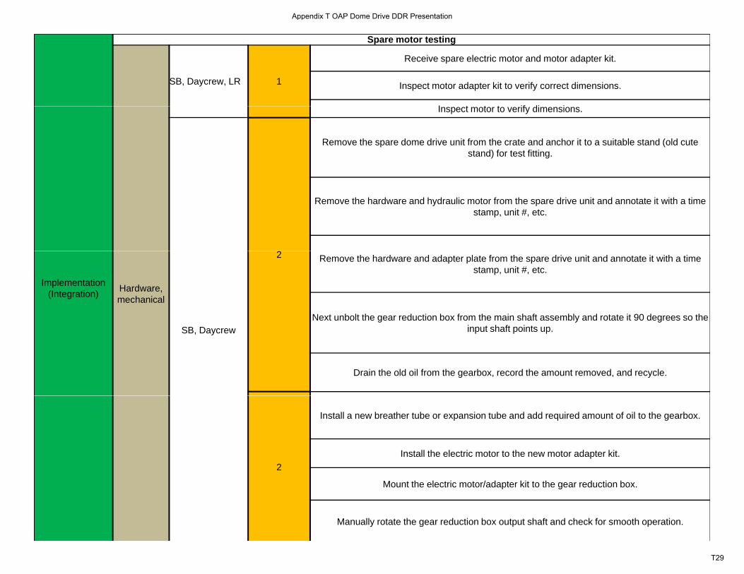
Spare motor testing
SB, Daycrew, LR 1
Receive spare electric motor and motor adapter kit.
Inspect motor adapter kit to verify correct dimensions.
I t t t if di iInspect motor to verify dimensions.
Remove the spare dome drive unit from the crate and anchor it to a suitable stand (old cute stand) for test fitting.
2
Remove the hardware and hydraulic motor from the spare drive unit and annotate it with a time stamp, unit #, etc.
Implementation(Integration) Hardware,
mechanical
2 Remove the hardware and adapter plate from the spare drive unit and annotate it with a time stamp, unit #, etc.
Next unbolt the gear reduction box from the main shaft assembly and rotate it 90 degrees so the SB, Daycrew input shaft points up.
Drain the old oil from the gearbox, record the amount removed, and recycle.
2
Install a new breather tube or expansion tube and add required amount of oil to the gearbox.
Install the electric motor to the new motor adapter kit.2
Mount the electric motor/adapter kit to the gear reduction box.
Manually rotate the gear reduction box output shaft and check for smooth operation.
Appendix T OAP Dome Drive DDR Presentation
T29
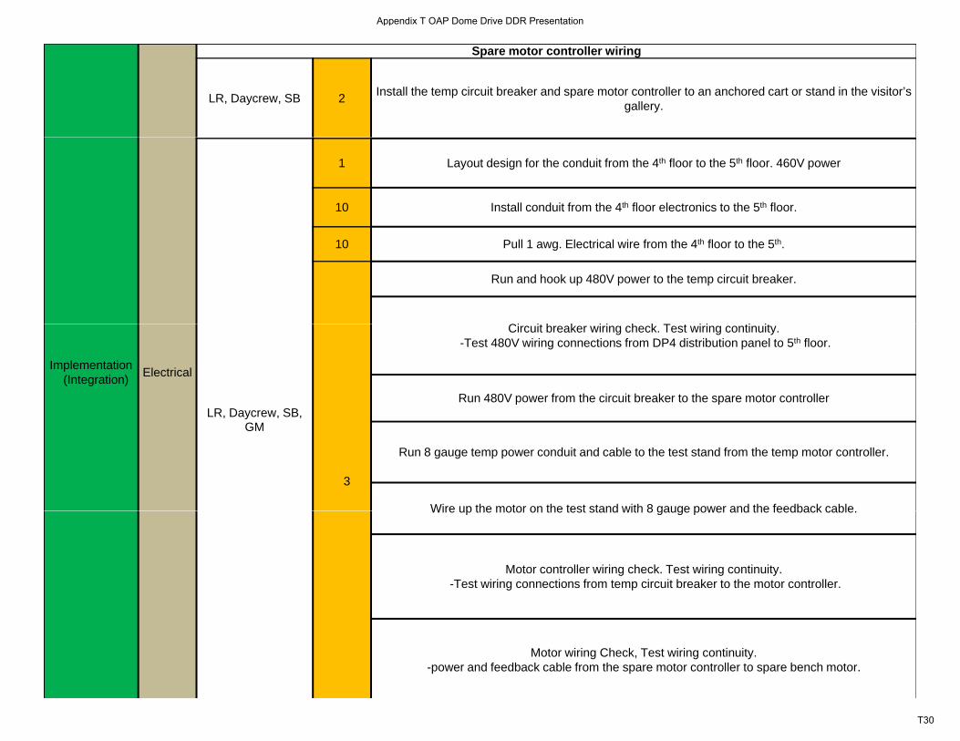
Spare motor controller wiring
LR, Daycrew, SB 2 Install the temp circuit breaker and spare motor controller to an anchored cart or stand in the visitor’s gallery.
1 Layout design for the conduit from the 4th floor to the 5th floor. 460V power
10 Install conduit from the 4th floor electronics to the 5th floor.
10 Pull 1 awg. Electrical wire from the 4th floor to the 5th.
Run and hook up 480V power to the temp circuit breaker.
Ci it b k i i h k T t i i ti it
Implementation(Integration) Electrical
LR, Daycrew, SB,
Circuit breaker wiring check. Test wiring continuity.-Test 480V wiring connections from DP4 distribution panel to 5th floor.
Run 480V power from the circuit breaker to the spare motor controller, y , ,
GM
3
Run 8 gauge temp power conduit and cable to the test stand from the temp motor controller.
Wire up the motor on the test stand with 8 gauge power and the feedback cableWire up the motor on the test stand with 8 gauge power and the feedback cable.
Motor controller wiring check. Test wiring continuity.-Test wiring connections from temp circuit breaker to the motor controller.
Motor wiring Check, Test wiring continuity. -power and feedback cable from the spare motor controller to spare bench motor.
Appendix T OAP Dome Drive DDR Presentation
T30

Spare motor controller testingSee section 7 for. implementation plan for the control of the system
GM
1 Modify the PLC Panel in the computer room
1 Cabling between computer room PLC and dome drive cabinet location 5th floor.
2 PLC code modification
Implementation(Integration) Software and control
4 Integration of the controls3 Testing of the PLC controls3 Air actuator testing4 Motor testing
2 Spare motor controller and spare bench motor testing complete. Awaiting Baldor cabinet for integration.
TV, SB,GM 3
PLC communication for status monitoring
RS232 to Perle communication for status monitoringStatus page design
Status/monitoring page testDrive unit motor conduit and wiring
Electrical LR Daycrew SB
1 Finalize the layout design (floor plan) for the conduit from the 4th floor to the 5th floor. 460V power
2 Layout design (floor plan) for 2 sets of conduit (1/2” and ¾”) for the motor power and feedback cables.
5 Install 2 sets of conduit (1/2” and ¾”) for the motor power and feedback cables
Implementation(Integration)
Electrical LR, Daycrew, SB 5 Install 2 sets of conduit (1/2 and ¾ ) for the motor power and feedback cables.
5 Pull 8 gauge wires for motors, i.e. electrical wire from the drive units to the drive cabinet location
1 Motor Wiring Check, Test wiring continuity. -power and feedback cable from drive units to motor controller cabinet( g )
Drive cabinet integration
Hardware
SB,LF 1 Receive Baldor drive unit cabinet at HQSB,RW 1 Transport the cabinet to the summit.
SB, Daycrew 1 Install the cabinet in the 5th floor visitor’s gallery and secure it in place.
LR 1 Connect 1awg wiring to the drive unit Test functionalityHardware,MechanicalElectrical
LR 1 Connect 1awg wiring to the drive unit. Test functionality
LR, Daycrew, SB, GM
Motor controller wiring check. Test wiring continuity.-Test wiring connections from circuit breaker and PLC to the motor controller.
LR, SB,Daycrew 1 Finish motor controller cabinet install and checkout.
Appendix T OAP Dome Drive DDR Presentation
T31

Drive unit Integration
SB,Daycrew 2 Hydraulic motor retrofit can begins a few days before the cabinet is delivered or once the cabinet is integrated
Remove hardware, old hydraulic motor, and adapter kit from drive unit #2.
Remove hardware and rotate the Brevini gearbox 90 degrees so the input shaft is upRemove hardware and rotate the Brevini gearbox 90 degrees so the input shaft is up.
Assemble the new adapter kit/electric motor combination.
Install new assembly to the Brevini gear reduction box on drive unit #2
WC, GM, SB 4 TCS/PLC/cabinet Testing with new electric drive unit #2
SB
H d
SB, Consultant 1 Motor controller consultant arrives on island (this can occur before the first unit is integrated or after)
SB, Daycrew,
WC,GM,
Consultant
2 Dome drive Consultation Commissioning and Testing-Begin day testing of VFD system.
T d i i # 2 d l i l
Implementation(Integration)
Hardware,MechanicalElectrical
Test drive unit # 2 under electric motor controlSB,
Daycrew 1 Prefer to perform Unit #3 retrofit when F/8 is on telescope
Remove old hydraulic motor and adapter kit from drive unit #3Rotate Brevini gearbox 90 degrees
Install new Brevini adapter kit on drive unit #3Install new Electric motor on drive unit # 3
SB, Daycrew,
WC,GM,
Consultant
2 Test drive unit # 2 and 3 under electric motor control.
New electric drive system Commissioned and ready for nightly operations under two drive unit operationsNew electric drive system Commissioned and ready for nightly operations-under two drive unit operations temporarily.
SB,Daycrew 3 Remove old hydraulic motor and adapter kit from drive unit #1
Rotate Brevini gearbox 90 degreesInstall new Brevini adapter kit on drive unit #1
Install new Electric motor on drive unit # 1Install new Electric motor on drive unit # 1
See section 7 for. implementation plan for the control of the system
Software, Electrical
SB, GM, WC, Daycrew
5 Test drive unit # 1, 2 and 3 under electric motor control.1 Manual/automatic system tests
3 Phase 1 Finished- Dome drive system now under electric drive system control.
Appendix T OAP Dome Drive DDR Presentation
T32

1 1
Baldor ZD22H420EL drive panel package proposal $43,860.53 $43,860.53
Drive system package, 3X motor controllers and equipment needed to assemble drive cabinet, for more information.
Baldor 20HP RPM AC ZDFRPM21204C $3 096 00 $9 288 00 Drive system motors, 3X motors. 1 Master and 2 Slaves, for more
Equipment and Material CostsItem Qty Component description Cost Total Notes/Includes:
2 3 motor $3,096.00 $9,288.00 information.
3 1
Baldor-spare 20HP RPM AC ZDFRPM21204C motor
$3,096.00*Shipping:*$243.37
$3,339.38Spare drive system motor, special pricing when purchased as a package, for more information.
4 1
Baldor-spare ZD22H425EL motor controller $8,660.00*Shipping:*$243 37
$8,903.38Spare drive system motor controller, special pricing when purchased as a package, for more information.
$243.37
5 1
Baldorapplications engineer for drive commissioning
$5000.00 $5000.00Plus travel expenses, i.e. airfare, lodging, rental car.
6 1HFB3150-R, 150amp 600 volt 3 pole circuit breaker
$650.00*Shipping:*$69.45
$719.45Southland Electrical Supply, for more information
7 1
Gexpro-Electrical conduit and wiring upgrades $3,868.84 $3,868.84
New 1awg wiring and conduit run from the 4th floor to the 5th floor, 8 gauge wire and conduit for the motor power runs, for more information
8 4Parker Hannifin Pneumatic actuators for the dome drive frames $623.67 $2,530.68 Includes: four (4) Pneumatic actuators, (1) one is a spare, for more cost
information. Parker HannifinFemale Rod clevis brackets for the dome $50 95 $203 80
Includes: Four (4) Female rod clevis, (1) one is a spare, for more cost information10 4 Female Rod clevis brackets for the dome
drive frames $50.95 $203.80 information.
11 4Parker HannifinPivot pins for the dome drive frames $21.85 $87.40 Includes: four (4) Pivot pins, (1) one is a spare, for more cost
information.
12 4Pneumatic Solenoid valves, air lines, and fittings $655.00 $2,620.00 Includes: four (4) Solenoid valves, (1) one spare, for more cost
information.Brevini $606 70 $ 2 426 80 Includes (4) motor adapter kits, (1) one spare kit, for more cost
13 4 Motor adapter kits-qty 4 $606.70 $ 2,426.80 ( ) p , ( ) p ,information.
14 1
Heat mitigation• Option1: Vent cabinet into the visitors
gallery• Option 2: Fan above the stair access
doorO ti 3 H t h ith l l
$1,500.00 $1,500.00 This is the cost for the third option in the heat mitigation.The second option will cost around $600.00Option 1 has no added costs
• Option 3:Heat exchanger with glycol lines and fittings
Misc materials and supplies $1,000.00TOTAL $85,348.26
Appendix T OAP Dome Drive DDR Presentation
T33
Any Additional Questions or Comments?
?QUESTIONS, COMMENTS?
Thank you for your time!
Appendix T OAP Dome Drive DDR Presentation
T34