Embed Size (px)
Citation preview
EAEC05YU-AS04
NUMERICAL AND EXPERIMENTAL ANALYSIS OF A PEGS-WING VENTILATED DISK BRAKE ROTOR,
WITH PADS AND CYLINDERS
Pier Francesco Gotowicki, Prof. Vinzenco Nigrelli, Prof. Gabriele Virzi Mariotti Universita degli studi di Palermo, Dipartimento di Meccanica, Italy
Mgr. Dipl. Ing. Dragan Aleksendric, Prof. Dr. Cedomir Duboka, University of Belgrade, Serbia
10th EAEC European Automotive Congress – Paper EAEC05YU-AS04 - Page 1
Abstract The results of the braking numerical simulations on a pegs-wing ventilated disk brake rotor, obtained by performing a fading braking procedure, are compared with the experimental ones obtained in the same brake, mounted on a work bench, in the same fading braking procedure. The numerical simulations are performed on the entire disk, besides some structural parameters, thermal conductivity, specific heat and elastic modulus, are considered as a function of the temperature; the other parameters are considered as constant. The results of the numerical simulations are in a good agreement with the experimental ones. It is also shown that numerical calculations can be considered conservative, since the numerical thermal field is a little bit higher than the experimental one. Furthermore the pegs-wing ventilated disk brake rotor is able to dissipate a great amount of thermal flux showing a great dimensional stability. Key words: Disk brake rotor, pads, caliper, finite elements, thermal stress, fading testing procedure. 1. Introduction Disk brakes have great diffusion because permit a strong and modulating braking; today they are coupled with mechatronic systems as A.B.S. [1] [2]. During the walking the vehicle is endowed
with kinetic energy: 2
2vmKEc
⋅⋅= , where m is the mass of vehicle, v the velocity and K an inertia
coefficient; the brakes have the purpose to diminish or destroy this energy dissipating it in heat. Because temperature of 400° - 500° C are obtained during a demanding braking the materials have to be able to support the high mechanics and thermal stress. The disk brake and the pads have to own a high thermal conductibility, a high volume – surface ratio a high mechanical resistance and to wear. The disk must have limited mass in order to diminish the inertia forces and non-suspending mass; moreover it cannot endure high strain in the braking zone in order to maintain uniform the contact with pads [3] [4]. In a more recent times the problem was treated by Finite Element Method, at first in an axial symmetric way, after in a entire field [5 – 8] in order to obtain a more accurate description of the stress and strain in the disk under thermal and mechanic solicitation. The disk brake problem is discussed in a mixed theoretical way [9 - 12] by making use of Romiti theory; it is obtained applying Reye hypothesis on the pad – disk contact. Furthermore a thermo -
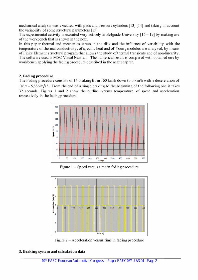
mechanical analysis was executed with pads and pressure cylinders [13] [14] and taking in account the variability of some structural parameters [15]. The experimental activity is executed very actively in Belgrade University [16 – 19] by making use of the workbench that is shown in the next. In this paper thermal and mechanics stress in the disk and the influence of variability with the temperature of thermal conductivity, of specific heat and of Young modulus are analysed, by means of Finite Element structural program that allows the study of thermal transients and of non-linearity. The software used is MSC Visual Nastran. The numerical result is compared with obtained one by workbench applying the fading procedure described in the next chapter. 2. Fading procedure The Fading procedure consists of 14 braking from 160 km/h down to 0 km/h with a deceleration of
2sm 886,56,0 =g . From the end of a single braking to the beginning of the following one it takes 32 seconds. Figures 1 and 2 show the outline, versus temperature, of speed and acceleration respectively in the fading procedure.
Figure 1 – Speed versus time in fading procedure
Figure 2 – Acceleration versus time in fading procedure
10th EAEC European Automotive Congress – Paper EAEC05YU-AS04 - Page 2
3. Braking system and calculation data
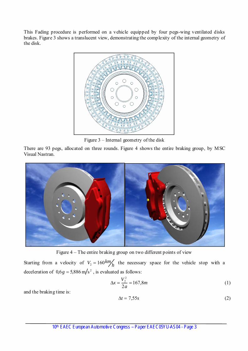
This Fading procedure is performed on a vehicle equipped by four pegs-wing ventilated disks brakes. Figure 3 shows a translucent view, demonstrating the complexity of the internal geometry of the disk.
Figure 3 – Internal geometry of the disk
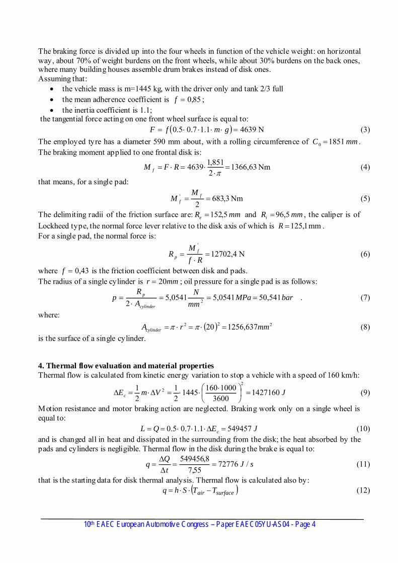
There are 93 pegs, allocated on three rounds. Figure 4 shows the entire braking group, by MSC Visual Nastran.
Figure 4 – The entire braking group on two different points of view
Starting from a velocity of hkmV 1602 = the necessary space for the vehicle stop with a
deceleration of 2sm 886,56,0 =g , is evaluated as follows:
ma
Vx 8,167
2
22 ==Δ (1)
and the braking time is: st 55,7=Δ (2)
10th EAEC European Automotive Congress – Paper EAEC05YU-AS04 - Page 3
The braking force is divided up into the four wheels in function of the vehicle weight: on horizontal way, about 70% of weight burdens on the front wheels, while about 30% burdens on the back ones, where many building houses assemble drum brakes instead of disk ones. Assuming that:
• the vehicle mass is m=1445 kg, with the driver only and tank 2/3 full • the mean adherence coefficient is 85,0=f ; • the inertia coefficient is 1.1;
the tangential force acting on one front wheel surface is equal to: (3) ( ) N 46391.17.05.0 =⋅⋅⋅⋅= gmfFThe employed tyre has a diameter 590 mm about, with a rolling circumference of . The braking moment applied to one frontal disk is:
mmC 18510 =
Nm 63,13662851,14639 =⋅
⋅=⋅=π
RFM f (4)
that means, for a single pad:
Nm 3,6832
' == ff
MM (5)
The delimiting radii of the friction surface are: and , the caliper is of Lockheed type, the normal force lever relative to the disk axis of which is
mmRe 5,152= mmRi 5,96=mm 1,125=R .
For a single pad, the normal force is:
N 4,12702'
=⋅
=Rf
MR f
p (6)
where 43,0=f is the friction coefficient between disk and pads. The radius of a single cylinder is ; oil pressure for a single pad is as follows: mmr 20=
. 50,541 0541,50541,52 2 barMPa
mmN
AR
pcylinder
p ===⋅
= (7)
where: (8) ( ) 222 637,125620 mmrAcylinder =⋅=⋅= ππis the surface of a single cylinder. 4. Thermal flow evaluation and material properties Thermal flow is calculated from kinetic energy variation to stop a vehicle with a speed of 160 km/h:
JVmEc 14271603600
1000160144521
21
22 =⎟
⎠⎞
⎜⎝⎛ ⋅⋅⋅=Δ⋅=Δ (9)
Motion resistance and motor braking action are neglected. Braking work only on a single wheel is equal to: (10) JEQL c 5494571.17.05.0 =Δ⋅⋅⋅==and is changed all in heat and dissipated in the surrounding from the disk; the heat absorbed by the pads and cylinders is negligible. Thermal flow in the disk during the brake is equal to:
sJtQ
q / 7277655,7
8,549456==
ΔΔ
= (11)
that is the starting data for disk thermal analysis. Thermal flow is calculated also by: ( )surfaceair TTShq −⋅⋅= (12)
10th EAEC European Automotive Congress – Paper EAEC05YU-AS04 - Page 4
where h is the convection coefficient, equal toKm
Wh
°−= 210090 , by experimental determinations
of the brake industry; S is the braking surface. Thermal flow and convection are simultaneously applied for all the braking duration. The program requires the specific (unit of time and surface) thermal flow in the disk, equal to:
283065,0mmW
Sqqflux
specific == (13)
being the surface equal to: ( ) 222 7,876122 mmRRS ieflux =−⋅⋅= π (14)
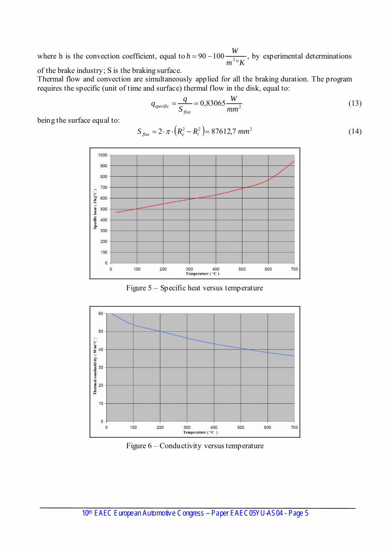
Figure 5 – Specific heat versus temperature
Figure 6 – Conductivity versus temperature
10th EAEC European Automotive Congress – Paper EAEC05YU-AS04 - Page 5
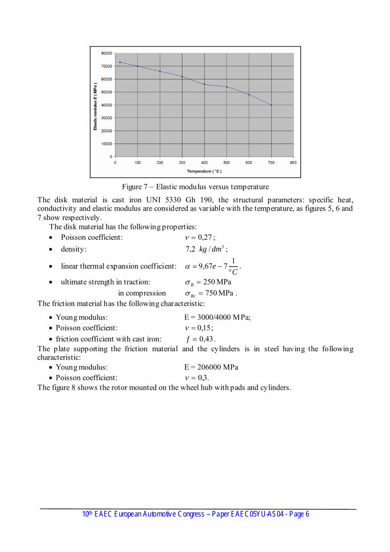
Figure 7 – Elastic modulus versus temperature
The disk material is cast iron UNI 5330 Gh 190, the structural parameters: specific heat, conductivity and elastic modulus are considered as variable with the temperature, as figures 5, 6 and 7 show respectively.
The disk material has the following properties: • Poisson coefficient: 27,0=ν ; • density: ; 3/2,7 dmkg
• linear thermal expansion coefficient: C
e°
−=1
767,9α .
• ultimate strength in traction: MPa 250=Rσ in compression . MPa 750=Rcσ
The friction material has the following characteristic:
• Young modulus: E = 3000/4000 MPa; • Poisson coefficient: 15,0=ν ; • friction coefficient with cast iron: 43,0=f .
The plate supporting the friction material and the cylinders is in steel having the following characteristic:
• Young modulus: E = 206000 MPa • Poisson coefficient: .3,0=ν
The figure 8 shows the rotor mounted on the wheel hub with pads and cylinders.
10th EAEC European Automotive Congress – Paper EAEC05YU-AS04 - Page 6
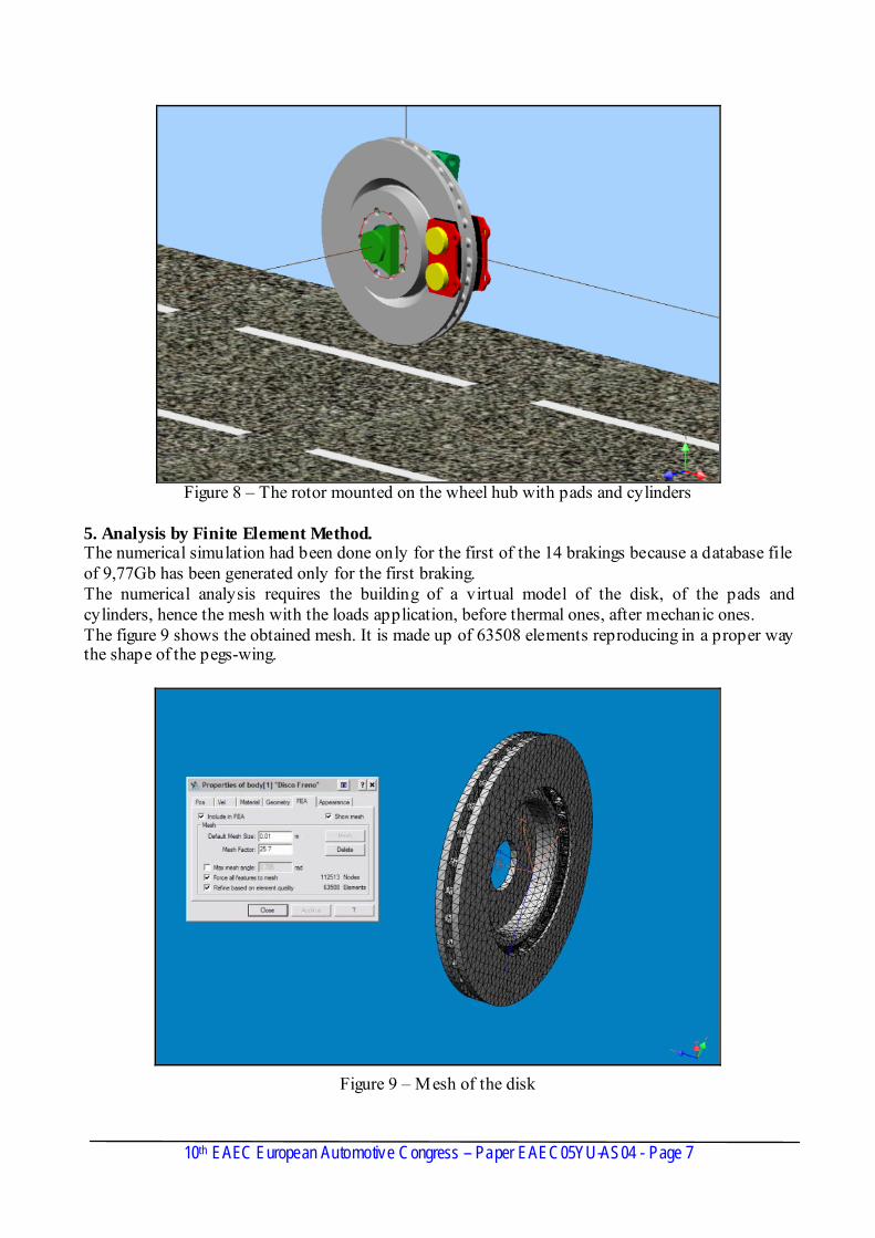
Figure 8 – The rotor mounted on the wheel hub with pads and cylinders
5. Analysis by Finite Element Method. The numerical simulation had been done only for the first of the 14 brakings because a database file of 9,77Gb has been generated only for the first braking. The numerical analysis requires the building of a virtual model of the disk, of the pads and cylinders, hence the mesh with the loads application, before thermal ones, after mechanic ones. The figure 9 shows the obtained mesh. It is made up of 63508 elements reproducing in a proper way the shape of the pegs-wing.
Figure 9 – Mesh of the disk
10th EAEC European Automotive Congress – Paper EAEC05YU-AS04 - Page 7
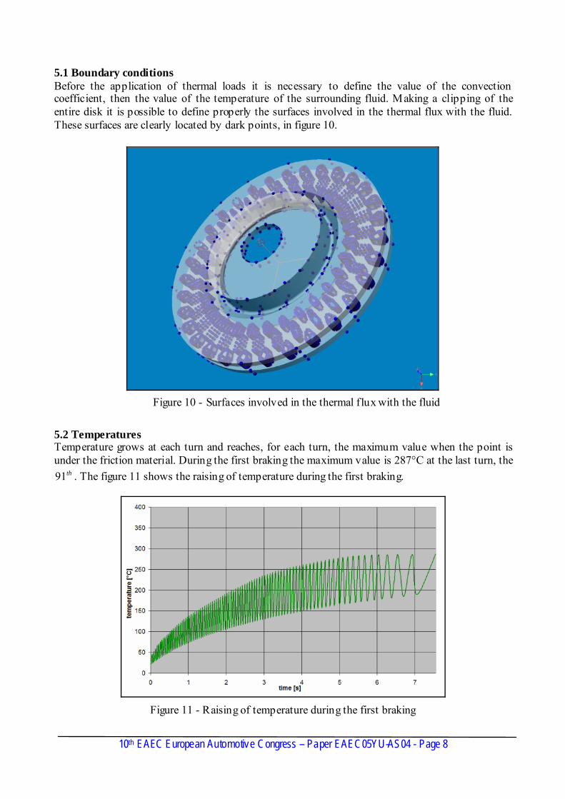
5.1 Boundary conditions Before the application of thermal loads it is necessary to define the value of the convection coefficient, then the value of the temperature of the surrounding fluid. Making a clipping of the entire disk it is possible to define properly the surfaces involved in the thermal flux with the fluid. These surfaces are clearly located by dark points, in figure 10.
Figure 10 - Surfaces involved in the thermal flux with the fluid
5.2 Temperatures Temperature grows at each turn and reaches, for each turn, the maximum value when the point is under the friction material. During the first braking the maximum value is 287°C at the last turn, the
. The figure 11 shows the raising of temperature during the first braking. th91
Figure 11 - Raising of temperature during the first braking
10th EAEC European Automotive Congress – Paper EAEC05YU-AS04 - Page 8
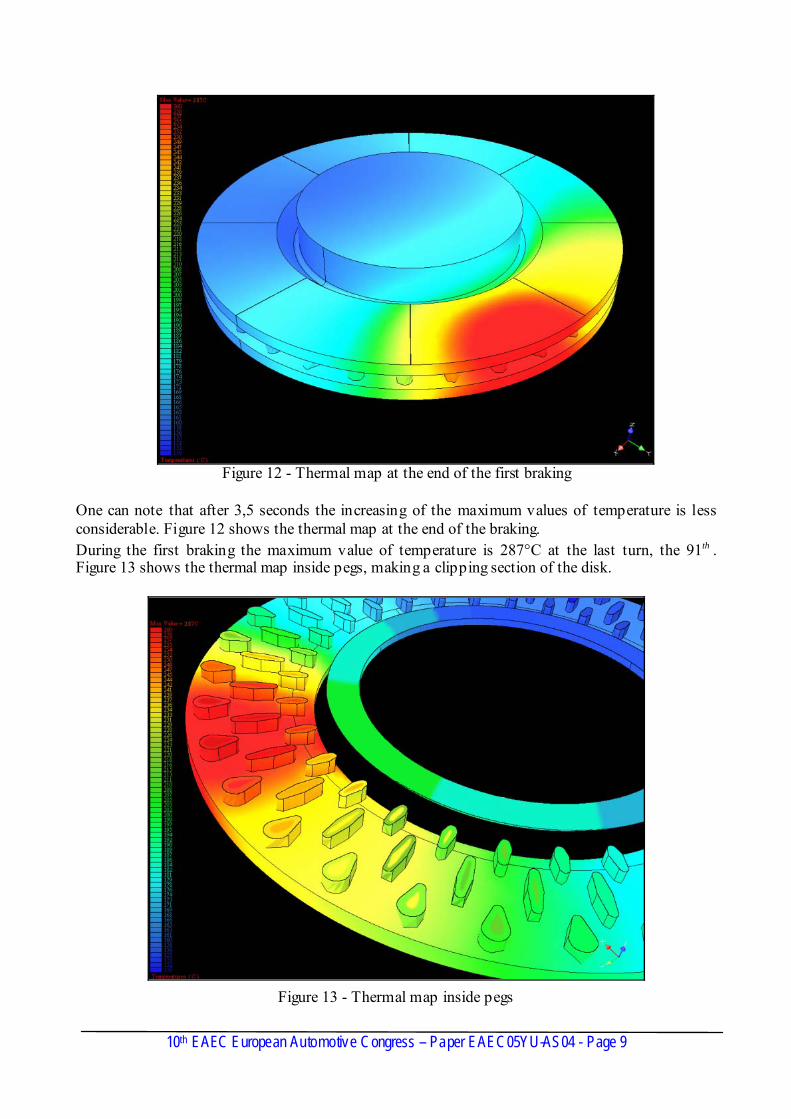
Figure 12 - Thermal map at the end of the first braking
One can note that after 3,5 seconds the increasing of the maximum values of temperature is less considerable. Figure 12 shows the thermal map at the end of the braking. During the first braking the maximum value of temperature is 287°C at the last turn, the . Figure 13 shows the thermal map inside pegs, making a clipping section of the disk.
th91
Figure 13 - Thermal map inside pegs
10th EAEC European Automotive Congress – Paper EAEC05YU-AS04 - Page 9
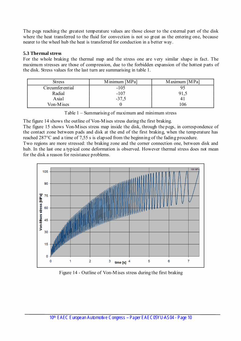
The pegs reaching the greatest temperature values are those closer to the external part of the disk where the heat transferred to the fluid for convection is not so great as the entering one, because nearer to the wheel hub the heat is transferred for conduction in a better way. 5.3 Thermal stress For the whole braking the thermal map and the stress one are very similar shape in fact. The maximum stresses are those of compression, due to the forbidden expansion of the hottest parts of the disk. Stress values for the last turn are summarising in table 1.
Stress Minimum [MPa] Maximum [MPa] Circumferential -105 95
Radial -107 91,5 Axial -37,5 41
Von-Mises 0 106
Table 1 – Summarising of maximum and minimum stress
The figure 14 shows the outline of Von-Mises stress during the first braking. The figure 15 shows Von-Mises stress map inside the disk, through the pegs, in correspondence of the contact zone between pads and disk at the end of the first braking, when the temperature has reached 287°C and a time of 7,55 s is elapsed from the beginning of the fading procedure. Two regions are more stressed: the braking zone and the corner connection one, between disk and hub. In the last one a typical cone deformation is observed. However thermal stress does not mean for the disk a reason for resistance problems.
Figure 14 - Outline of Von-Mises stress during the first braking
10th EAEC European Automotive Congress – Paper EAEC05YU-AS04 - Page 10
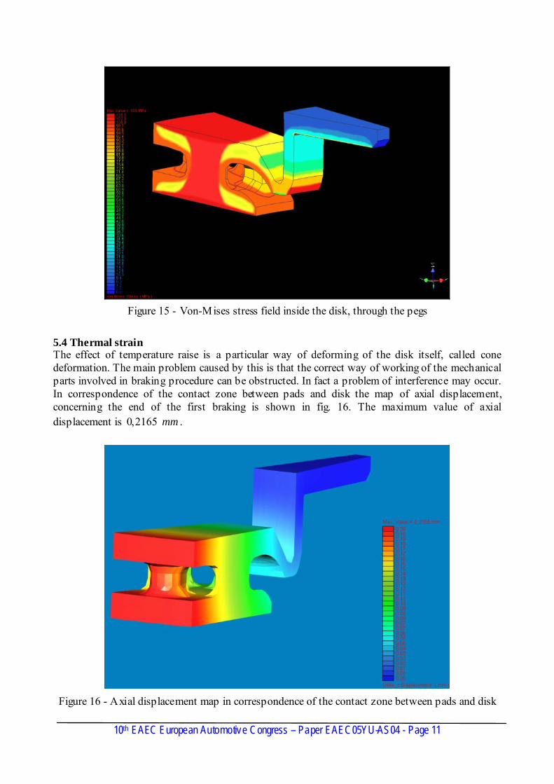
Figure 15 - Von-Mises stress field inside the disk, through the pegs
5.4 Thermal strain The effect of temperature raise is a particular way of deforming of the disk itself, called cone deformation. The main problem caused by this is that the correct way of working of the mechanical parts involved in braking procedure can be obstructed. In fact a problem of interference may occur. In correspondence of the contact zone between pads and disk the map of axial displacement, concerning the end of the first braking is shown in fig. 16. The maximum value of axial displacement is mm2165,0 .
Figure 16 - Axial displacement map in correspondence of the contact zone between pads and disk
10th EAEC European Automotive Congress – Paper EAEC05YU-AS04 - Page 11
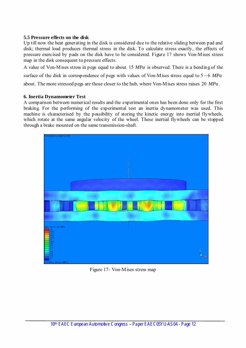
5.5 Pressure effects on the disk Up till now the heat generating in the disk is considered due to the relative sliding between pad and disk; thermal load produces thermal stress in the disk. To calculate stress exactly, the effects of pressure exercised by pads on the disk have to be considered. Figure 17 shows Von-Mises stress map in the disk consequent to pressure effects. A value of Von-Mises stress in pegs equal to about is observed. There is a bending of the
surface of the disk in correspondence of pegs with values of Von-Mises stress equal to
about. The more stressed pegs are those closer to the hub, where Von-Mises stress raises .
MPa15
MPa65 −
MPa20 6. Inertia Dynamometer Test A comparison between numerical results and the experimental ones has been done only for the first braking. For the performing of the experimental test an inertia dynamometer was used. This machine is characterised by the possibility of storing the kinetic energy into inertial flywheels, which rotate at the same angular velocity of the wheel. These inertial flywheels can be stopped through a brake mounted on the same transmission-shaft.
Figure 17- Von-Mises stress map
10th EAEC European Automotive Congress – Paper EAEC05YU-AS04 - Page 12
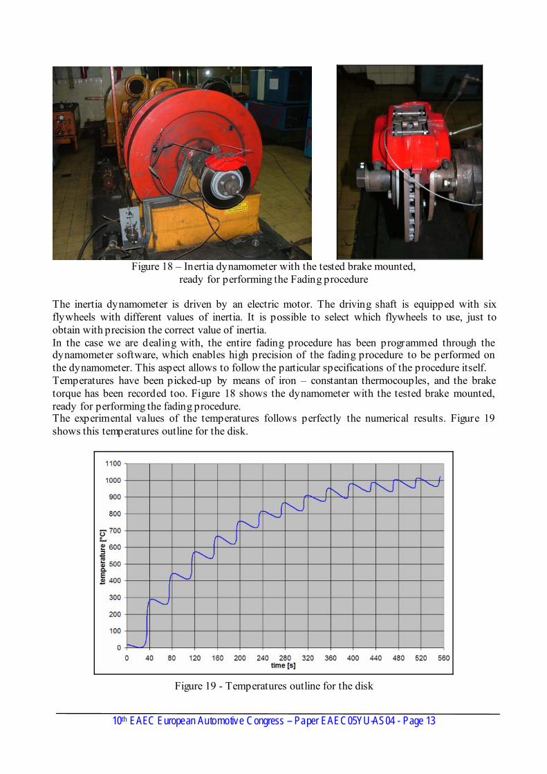
Figure 18 – Inertia dynamometer with the tested brake mounted,
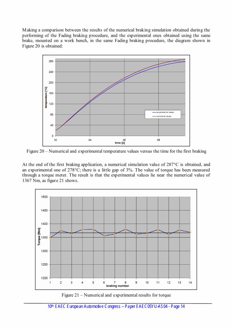
ready for performing the Fading procedure The inertia dynamometer is driven by an electric motor. The driving shaft is equipped with six flywheels with different values of inertia. It is possible to select which flywheels to use, just to obtain with precision the correct value of inertia. In the case we are dealing with, the entire fading procedure has been programmed through the dynamometer software, which enables high precision of the fading procedure to be performed on the dynamometer. This aspect allows to follow the particular specifications of the procedure itself. Temperatures have been picked-up by means of iron – constantan thermocouples, and the brake torque has been recorded too. Figure 18 shows the dynamometer with the tested brake mounted, ready for performing the fading procedure. The experimental values of the temperatures follows perfectly the numerical results. Figure 19 shows this temperatures outline for the disk.
Figure 19 - Temperatures outline for the disk
10th EAEC European Automotive Congress – Paper EAEC05YU-AS04 - Page 13
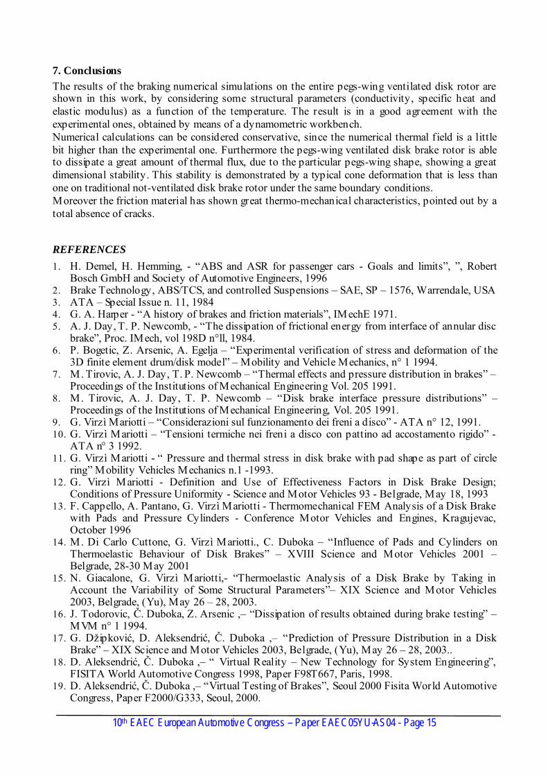
Making a comparison between the results of the numerical braking simulation obtained during the performing of the Fading braking procedure, and the experimental ones obtained using the same brake, mounted on a work bench, in the same Fading braking procedure, the diagram shown in Figure 20 is obtained:
Figure 20 – Numerical and experimental temperature values versus the time for the first braking
At the end of the first braking application, a numerical simulation value of 287°C is obtained, and an experimental one of 278°C; there is a little gap of 3%. The value of torque has been measured through a torque meter. The result is that the experimental values lie near the numerical value of 1367 Nm, as figure 21 shows.
10th EAEC European Automotive Congress – Paper EAEC05YU-AS04 - Page 14
Figure 21 – Numerical and experimental results for torque
7. Conclusions The results of the braking numerical simulations on the entire pegs-wing ventilated disk rotor are shown in this work, by considering some structural parameters (conductivity, specific heat and elastic modulus) as a function of the temperature. The result is in a good agreement with the experimental ones, obtained by means of a dynamometric workbench. Numerical calculations can be considered conservative, since the numerical thermal field is a little bit higher than the experimental one. Furthermore the pegs-wing ventilated disk brake rotor is able to dissipate a great amount of thermal flux, due to the particular pegs-wing shape, showing a great dimensional stability. This stability is demonstrated by a typical cone deformation that is less than one on traditional not-ventilated disk brake rotor under the same boundary conditions. Moreover the friction material has shown great thermo-mechanical characteristics, pointed out by a total absence of cracks.
REFERENCES 1. H. Demel, H. Hemming, - “ABS and ASR for passenger cars - Goals and limits”, ”, Robert
Bosch GmbH and Society of Automotive Engineers, 1996 2. Brake Technology, ABS/TCS, and controlled Suspensions – SAE, SP – 1576, Warrendale, USA 3. ATA – Special Issue n. 11, 1984 4. G. A. Harper - “A history of brakes and friction materials”, IMechE 1971. 5. A. J. Day, T. P. Newcomb, - “The dissipation of frictional energy from interface of annular disc
brake”, Proc. IMech, vol 198D n°ll, 1984. 6. P. Bogetic, Z. Arsenic, A. Egelja – “Experimental verification of stress and deformation of the
3D finite element drum/disk model” – Mobility and Vehicle Mechanics, n° 1 1994. 7. M. Tirovic, A. J. Day, T. P. Newcomb – “Thermal effects and pressure distribution in brakes” –
Proceedings of the Institutions of Mechanical Engineering Vol. 205 1991. 8. M. Tirovic, A. J. Day, T. P. Newcomb – “Disk brake interface pressure distributions” –
Proceedings of the Institutions of Mechanical Engineering, Vol. 205 1991. 9. G. Virzì Mariotti – “Considerazioni sul funzionamento dei freni a disco” - ATA n° 12, 1991. 10. G. Virzì Mariotti – “Tensioni termiche nei freni a disco con pattino ad accostamento rigido” -
ATA n° 3 1992. 11. G. Virzì Mariotti - “ Pressure and thermal stress in disk brake with pad shape as part of circle
ring” Mobility Vehicles Mechanics n.1 -1993. 12. G. Virzì Mariotti - Definition and Use of Effectiveness Factors in Disk Brake Design;
Conditions of Pressure Uniformity - Science and Motor Vehicles 93 - Belgrade, May 18, 1993 13. F. Cappello, A. Pantano, G. Virzì Mariotti - Thermomechanical FEM Analysis of a Disk Brake
with Pads and Pressure Cylinders - Conference Motor Vehicles and Engines, Kragujevac, October 1996
14. M. Di Carlo Cuttone, G. Virzì Mariotti., C. Duboka – “Influence of Pads and Cylinders on Thermoelastic Behaviour of Disk Brakes” – XVIII Science and Motor Vehicles 2001 – Belgrade, 28-30 May 2001
15. N. Giacalone, G. Virzì Mariotti,- “Thermoelastic Analysis of a Disk Brake by Taking in Account the Variability of Some Structural Parameters”– XIX Science and Motor Vehicles 2003, Belgrade, (Yu), May 26 – 28, 2003.
16. J. Todorovic, Č. Duboka, Z. Arsenic ,– “Dissipation of results obtained during brake testing” – MVM n° 1 1994.
17. G. Džipković, D. Aleksendrić, Č. Duboka ,– “Prediction of Pressure Distribution in a Disk Brake” – XIX Science and Motor Vehicles 2003, Belgrade, (Yu), May 26 – 28, 2003..
18. D. Aleksendrić, Č. Duboka ,– “ Virtual Reality – New Technology for System Engineering”, FISITA World Automotive Congress 1998, Paper F98T667, Paris, 1998.
10th EAEC European Automotive Congress – Paper EAEC05YU-AS04 - Page 15
19. D. Aleksendrić, Č. Duboka ,– “Virtual Testing of Brakes”, Seoul 2000 Fisita World Automotive Congress, Paper F2000/G333, Seoul, 2000.


![As04 c8.3 c8se Install and Config[1]](https://img.pdfslide.us/doc/110x75/5476655ab4af9fa90a8b603c/as04-c83-c8se-install-and-config1.jpg)


