Embed Size (px)
Citation preview
Acoustic Horn Design, Numerical and
Experimental Investigations of Ultrasonic
Vibration Assisted Turning of Ti-6Al-4V
Rudranarayan Kandi
Department of Mechanical Engineering
National Institute of Technology Rourkela
Acoustic Horn Design, Numerical and
Experimental Investigations of Ultrasonic
Vibration Assisted Turning of Ti-6Al-4V
Dissertation submitted in partial fulfilment
of the requirements for the degree of
Master of Technology (by Research)
in
Mechanical Engineering
by
Rudranarayan Kandi
(Roll Number: 614ME1002)
based on research carried out
under the supervision of
Prof. Susanta Kumar Sahoo
Jan, 2017
Department of Mechanical Engineering
National Institute of Technology Rourkela
i
Department of Mechanical Engineering
National Institute of Technology Rourkela
Jan 05, 2017
Certificate of Examination Roll Number: 614ME1002
Name: Rudranarayan Kandi
Title of Dissertation: Acoustic Horn Design, Numerical and Experimental Investigations
of Ultrasonic Vibration Assisted Turning of Ti-6Al-4V
We the below signed, after checking the dissertation mentioned above and the official
record book (s) of the student, hereby state our approval of the dissertation submitted in
partial fulfilment of the requirements for the degree of Master of Technology by Research
in Mechanical Engineering at National Institute of Technology Rourkela. We are satisfied
with the volume, quality, correctness, and originality of the work.
Prof. Susanta Kumar Sahoo
Principal Supervisor
Prof. Santosh Kumar Sahoo
Member, MSC
Prof. Mohammed Rajik Khan
Member, MSC
Prof. Siba Sankar Mohapatra
Chairperson, MSC
Head of the Department
Prof. Siba Sankar Mohapatra
Dr. Joyjeet Ghose
External Examiner

ii
Department of Mechanical Engineering
National Institute of Technology Rourkela
Prof. Susanta Kumar Sahoo
Professor
Jan 05, 2017
Supervisor’s Certificate
This is to certify that the work presented in the dissertation entitled Acoustic Horn Design,
Numerical and Experimental Investigations of Ultrasonic Vibration Assisted Turning of
Ti-6Al-4V submitted by Rudranarayan Kandi, Roll Number 614ME1002, is a record of
original research carried out by him under our supervision and guidance in partial
fulfilment of the requirements for the degree of Master of Technology by Research in
Mechanical Engineering. Neither this dissertation nor any part of it has been submitted
earlier for any degree or diploma to any institute or university in India or abroad.
Prof. Susanta Kumar Sahoo
Professor

iii
Dedication
Dedicated to my beloved parents, lovable friends, and
respected teachers
Rudranarayan Kandi

iv
Declaration of Originality
I, Rudranarayan Kandi, Roll Number 614ME1002 hereby declare that this dissertation
entitled Acoustic Horn Design, Numerical and Experimental Investigations of Ultrasonic
Vibration Assisted Turning of Ti-6Al-4V presents my original work carried out as an
M. Tech. (by Research) student of NIT Rourkela and, to the best of my knowledge,
contains no material previously published or written by another person, nor any material
presented by me for the award of any degree or diploma of NIT Rourkela or any other
institution. Any contribution made to this research by others, with whom I have worked at
NIT Rourkela or elsewhere, is explicitly acknowledged in the dissertation. Works of other
authors cited in this dissertation have been duly acknowledged under the sections
―Reference‖ or ―Bibliography‖. I have also submitted my original research records to the
scrutiny committee for evaluation of my dissertation.
I am fully aware that in case of any non-compliance detected in future, the Senate of
NIT Rourkela may withdraw the degree awarded to me on the basis of the present
dissertation.
Jan 05, 2017
NIT Rourkela Rudranarayan Kandi
v
Acknowledgement I, Rudranarayan Kandi, would like to express my special appreciation and thanks to my
guide, Prof. Sushanta Kumar Sahoo, Mechanical Engineering, National Institute of
Technology, Rourkela for his continuous encouragement and priceless supervision during
my research works. In the midst of the busy schedule, his sincere instructions and apt help
has comprehended this research work in stipulated time.
I wish to express my deep sense of gratitude to Prof. Siba Sankar Mohapatra, HOD,
Mechanical Engineering, National Institute of Technology, Rourkela for giving me an
opportunity to work on this project despite several departmental difficulties. I am very
much obliged to have him as my Chairperson in Masters Scrutiny Committee (MSC). I am
very much grateful to my MSC members: Prof. Prabal Kumar Ray, Department of
Mechanical Engineering, Prof. Mohammed Rajik Khan, Department of Industrial
Design, and Prof. Santosh Kumar Sahoo, Department of Metallurgical and Materials
Engineering. I am thankful to all the faculty members and technical staffs of Department
of Mechanical Engineering by allowing me laboratory facilities to carry out my research
works. I acknowledge with special thanks to Mr. Arabinda Khuntia, Production
engineering laboratory, Mr. Somma Tigga, Welding Shop, Mechanical Engineering.
I extend my special gratitude to Sushanta Sahu, Bikash Ranjan Moharana, Mantra
Prasad Satpathy, Srikar Potnuru, V.B. Shaibu and Kasinath Das Mohapatra, who were
my lab mates during my research works. I blissfully acknowledge to my seniors Sambit
Kumar Mohapatra, Swastik Pradhan, Alok Ranjan Biswal, and Subrat Kumar Bhuyan
for their support during the stay in National Institute of Technology, Rourkela. I do my
gratefulness to my beloved friends, Dilip Kumar Bagal, Satyabrata Tripathy, Somen
Biswal, Debasis Panda and Soubhagya Sahoo for their immense help and support in
every aspect of my life. Finally, special thanks to my parents Mr. Khirod Kumar Kandi
and Mrs. Kanaka Lata Das for all of the sacrifices that they have made on my behalf.
Jan 05, 2017
NIT Rourkela
Rudranarayan Kandi
614ME1002

vi
Abstract Titanium alloys have got wide ranges of applications in the field of aerospace, biomedical,
and marine industries owing to its unique properties like high strength, exceptional
corrosion resistance, and high strength to weight ratio. Still, characteristics like redduced
thermal conductivity and high affinity towards the cutting tools limit the machinability of
these alloys making these as the hard to cut alloys. Ultrasonic vibration assisted turning
(UVAT) is one of the novel machining processes enhancing the machinability of titanium
alloys compared to the conventional turning (CT). The process allows us to impose an
ultrasonic vibration of 20 kHz with small amplitude of vibration on the cutting insert to
get an intermittent cutting, unlike the conventional turning. The present work consists of
three parts (i) design and analysis of acoustic horn along with its fabrication (ii) finite
element model for both of the processes and experimental investigation with the
discussions, and (iii) machinability investigations of both the processes studying chip
morphology, surface integrity and tool wear. The first part includes designing and
modeling of the horn that will act as the tool holder in UVAT process, using Ansys v15®,
along with the fabrication of the parts based on the analysis. The tool holder is stepped
type made of stainless steel (Grade SS304) with flexible attachments for the cutting
inserts. The later part of the thesis includes preparation of 3D thermo-mechanical finite
element model for both the processes using Deform 3D®. Experimental investigations of
both the machining processes were carried out to study the machinability of titanium
Grade 5, TI-6Al-4V. The dependence of results (cutting force, surface roughness, tool
temperature, chip morphology etc.) on the input parameters were investigated and
compared. UVAT showed significant reductions in cutting forces with improved surface
finish of the workpiece. In the third section, machinability indices like chip morphology,
surface integrity, and tool wear were observed. The results confirm the suitability and
advantages of the UVAT process compared to the CT process to machine hard to cut
metal Ti-6Al-4V.
Keywords- Ti-6Al-4V; Ultrasonic vibration assisted turning; Acoustic horn;
machinability; Finite element model; Machinability indices
vii
Contents
Certificate of Examination i
Supervisor’s Certificate ii
Dedication iii
Declaration of Originality iv
Acknowledgement v
Abstract vi
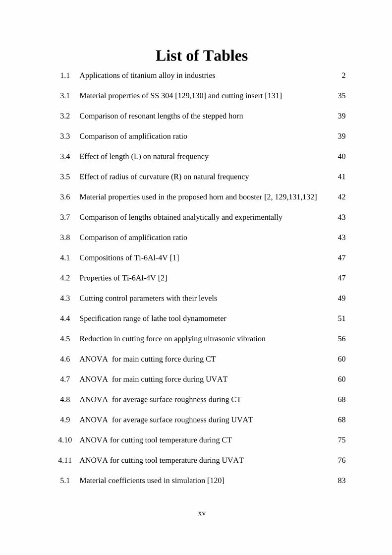
List of Figures xi
List of Tables xv
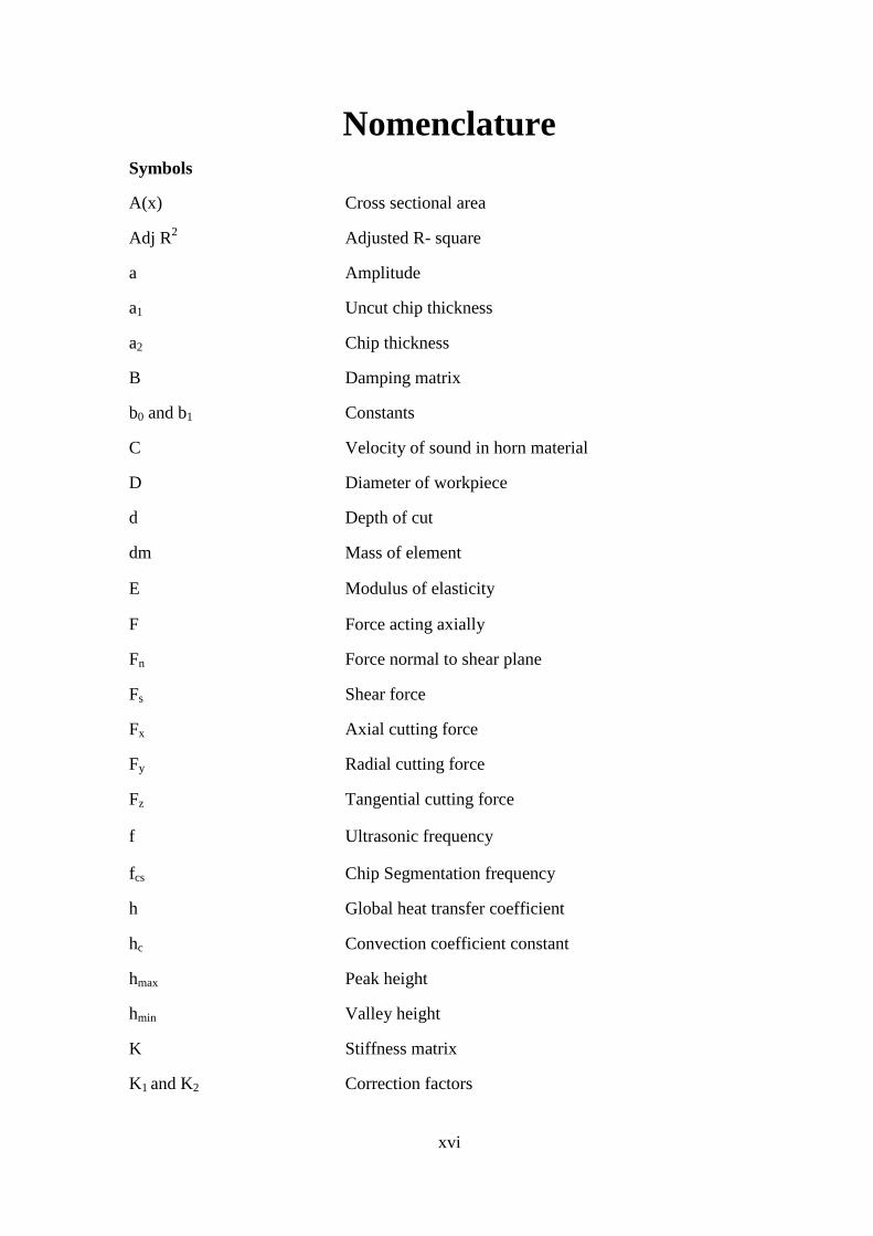
Nomenclature xvi
1 Introduction 1
1.1 Titanium Alloys 1
1.2 Turning Operation 2
1.2.1 Conventional turning (CT) 3
1.2.2 Cutting force 4
1.2.3 Cutting temperature 5
1.2.4 Chip formation 5
1.2.5 Surface integrity 7
1.2.6 Tool wear 7
1.2.7 Ultrasonic vibration assisted turning (UVAT) 8
1.2.8 Generation of ultrasonic vibration 9
1.3 Need for Simulation Modelling 9

viii
1.4 Motivation for the Present Research 10
1.5 Aim and Objectives of the Present Work 10
1.6 Thesis Organization 11
1.7 Closure 12
2 Literature Review 13
2.1 Turning of Titanium Alloys 13
2.2 Ultrasonic Vibration Assisted Turning (UVAT) 17
2.3 Acoustic Horn 22
2.4 Finite Element Analysis 24
2.5 Research Gaps 26
2.6 Novelty in the Present Work 27
2.7 Closure 27
3 Design, Analysis and Fabrication of Acoustic Horn 28
3.1 Acoustic Horn 28
3.2 Acoustic Wave Equation 29
3.3 Cylindrical Horn 31
3.4 Stepped Type Horn 33
3.5 Finite Element Modelling of Acoustic Horn 34
3.5.1 Modal analysis 36
3.5.2 Harmonic analysis 38
3.5.3 Mesh independence test 38
3.6 Comparison of Analytical and Experimental Results 39
ix
3.7 Horn Parameters on the Natural Frequency 40
3.8 Proposed Horn Design 42
3.8.1 Modal analysis results 43
3.8.2 Harmonic analysis results 44
3.9 Conclusions 46
4 Experimental Investigations 47
4.1 Titanium Alloy, Ti-6Al-4V 47
4.2 Experimental Setup and Measurements 48
4.2.1 Cutting force measurement 51
4.2.2 Cutting temperature measurement 51
4.2.3 Surface roughness measurement 52
4.2.4 Chip characteristics 53
4.2.5 Tool wear 53
4.3 Design of Experiment 53
4.4 Results and Discussion 54
4.4.1 Cutting force (Fz) 55
4.4.2 Surface roughness (Ra) 62
4.4.3 Cutting tool temperature (T) 70
4.5 Conclusions 76
5 Numerical Modelling and Comparison of Results 79
5.1 Numerical Modelling 79
5.1.1 Pre-processor 80
x
5.1.2 Simulation engine 81
5.1.3 Post-processor 81
5.2 Model Preparation for CT and UVAT 81
5.3 Simulation Results and Discussions 84
5.3.1 Cutting force validation 84
5.3.2 Tool temperature validation 89
5.4 Conclusions 93
6 Chip Morphology, Tool Wear, and Surface Integrity Investigations 95
6.1 Chip Morphology 95
6.2 Tool Wear 99
6.3 Surface Integrity 102
6.4 Effect of Lubrication 102
6.5 Conclusions 103
7 Conclusions 105
7.1 Major Findings 105
7.2 Conclusions 107
7.3 Scope of Future Works 108
Appendices 109
References 115
Dissemination 127

xi
List of Figures 1.1 Line diagram for Lathe 3
1.2 Merchant‘s Circle diagram [19] 4
1.3 Heat sources in metal cutting [19] 5
1.4 Various chips formed during turning process [19] 6
1.5 Tool wear region [33] 8
1.6 Different types of cutting vibrations in UVAT 8
2.1 Cutting tool positions in UVAT [75] 18
3.1 (a) Cylindrical (b) Stepped (c) Gaussian (d) Catenoidal (e) Bezier Type
horn 28
3.2 Non-uniform cylinder with a small element, dx [101] 29
3.3 Longitudinal vibration propagation in cylindrical horn with uniform area 31
3.4 Stepped type horn 33
3.5 (a) Stepped type horn, (b) Meshed geometry of the stepped horn 34
3.6 Longitudinal mode (1st mode) of the horn with frequency, 20005 Hz 36
3.7 Twisting mode (2nd
mode) of the horn with frequency, 25465 Hz 36
3.8 Bending mode (3rd
mode) of the horn with frequency, 27253 Hz 37
3.9 (a) Load applied as a function of displacement, 0.015 mm, (b)
Experimental set up for tuning of horn 37
3.10 Mesh independence test 38
3.11 Fabricated stepped horn with dimensions 39
3.12 (a) Amplitude amplification corresponding to the length of horn (b)
Directional deformation along the axis of the stepped horn 40
3.13 Wear and tear of the horn end due to repetitive use 41
3.14 (a) Booster dimensions, (b) Assembly of horn with booster 42
3.15 (a) Meshed model for booster with horn, (b) Longitudinal mode at 20008
Hz, (c) Bending mode at 20800Hz and (d) Twisting mode at 23485 Hz 43
3.16 (a) Amplitude amplification corresponding to the length of booster and
horn (b) Directional deformation along the axis of the assembly 44
3.17 Equivalent stress magnitude along the axis of the assembly 45

xii
3.18 Fabricated flexible stepped horn with dimension 45
4.1 Lathe machine with modified tool post for UVAT process 48
4.2 Various parts of UVAT 49
4.3 3D Schematic diagram for UVAT 49
4.4 Cutting insert, SNMG 120408 50
4.5 Additional experimental parts 50
4.6 Force history diagram during the experiment for both the processes 51
4.7 Temperature measurement set up 52
4.8 Surface measuring instrument 52
4.9 (a) Scanning electron microscope, (b) Radial microscope 53
4.10
Comparison of cutting forces at a constant velocity, Vc= 18 m/min with
various feeds (a) s= 0.04mm/rev, (b) s= 0.08 mm/rev (c) s= 0.12 mm/rev
(d) s= 0.16 mm/rev (e) s= 0.20 mm/rev
55
4.11
Effect of cutting velocity on cutting force keeping depth of cut constant,
d= 0.14mm with various feed (a) s=0.04mm/rev (b) s=0.0.08mm/rev (c)
s=0.12mm/rev (d) s=0.16mm/rev
57
4.12
Effect of feed on force keeping cutting velocity constant, Vc= 18 m/min
with various depth of cut (a) d=0.14mm (b) d=0.18 mm (c) d=0.22 mm
(d) d=0.26 mm
58
4.13
Effect of depth of cut on force keeping cutting velocity constant, Vc= 18
m/min with various feed (a) s=0.04mm/rev (b) s=0.08 mm/rev (c) s=0.12
mm/rev (d) s=0.16 mm/rev
59
4.14
(a) Effect of velocity and feed on force at depth of cut, d= 0.14mm (b)
Effect of velocity and depth of cut on force at feed rate, s= 0.04 mm/rev
(c) Effect of feed and depth of cut on force at velocity, Vc= 18m/min (For
CT)
61
4.15
(a) Effect of velocity and feed on force at depth of cut, d= 0.14 mm, (b)
Effect of depth of cut and velocity on force at feed rate, s= 0.04 m/min (c)
Effect of feed and depth of cut on force at velocity, Vc= 18 m/min (For
UVAT)
62
4.16
Comparison of surface roughness at a constant velocity, Vc= 18 m/min
with various feeds (a) s= 0.04mm/rev, (b) s= 0.08 mm/rev (c) s= 0.12
mm/rev (d) s= 0.16 mm/rev (e) s= 0.20 mm/rev
64
4.17
Effect of cutting velocity on surface roughness at constant depth of cut, d=
0.14mm with (a) s= 0.04 mm/rev, (b) s= 0.08 mm/rev, (c) s= 0.12
mm/rev, and (d) s= 0.16 mm/rev
65
xiii
4.18
Effect of feed on surface roughness at constant velocity, Vc= 18 m/min
with (a) d= 0.14 mm, (b) d= 0.18 mm, (c) d= 0.22 mm, and (d) d= 0.26
mm
66
4.19
Effect of depth of cut on surface roughness at constant velocity, Vc= 18
m/min with (a) s= 0.04 mm/rev, (b) s= 0.08 mm/rev, (c) s= 0.12 mm/rev,
and (d) s= 0.16 mm/rev
67
4.20
(a) Effect of velocity and feed on roughness at depth of cut, d= 0.14 mm,
(b) Effect of velocity and depth of cut at feed, s= 0.04 mm/rev (c) Effect
of depth of cut and feed on force at velocity, Vc= 18m/min. (For CT)
69
4.21
Effect of velocity and feed on roughness at depth of cut, d= 0.14 mm, (b)
Effect of velocity and depth of cut at feed, s= 0.04 mm/rev (c) Effect of
depth of cut and feed on force at velocity, Vc= 18m/min. (For UVAT)
70
4.22 Tool temperature comparison between CT and UVAT (at Vc= 18m/min
and 65m/min) for feed, s= 0.04 mm/rev 71
4.23 Effect of cutting velocity on the tool temperature at ‗d‘= 0.22mm 72
4.24 Effect of feed on cutting tool temperature at constant Vc =18 m/min and
(a) d= 0.14mm (b) d= 0.18mm (c) d= 0.22mm (d) d= 0.26 mm 73
4.25 Effect of depth of cut on tool temperature at constant Vc=18m/min with
(a) 0.04 mm/rev (b) 0.08 mm/rev (c) 0.12 mm/rev (d) 0.16 mm/rev 74
4.26
Effect of velocity and feed on tool temperature at depth of cut, d= 0.14
mm, (b) Effect of velocity and depth of cut at feed, s= 0.04 mm/rev (c)
Effect of depth of cut and feed on force at velocity, Vc= 18m/min. (For
CT)
75
4.27
Effect of velocity and feed on tool temperature at depth of cut, d= 0.14
mm, (b) Effect of velocity and depth of cut at feed, s= 0.04 mm/rev (c)
Effect of depth of cut and feed on force at velocity, Vc= 18m/min. (For
UVAT)
76
5.1 (a) Meshed Workpiece with dimension (b) Meshed cutting tool 82
5.2 Boundary conditions with tool movement as a function of velocity 82
5.3 Comparison of main cutting forces with the measured results (a) CT (b)
UVAT 86
5.4 (a) Force generation from Deform 3D® for both CT and UVAT (b) single
cycle of a UVAT simulation with reduction in average cutting force 87
5.5 Transient cutting in UVAT at Vc= 18m/min, s= 0.04mm/rev and d= 0.14
mm 87
5.6 Continuous cutting in CT at Vc= 18m/min, s= 0.04mm/rev and d= 0.14
mm 88

xiv
5.7
Effect of cutting velocity on the main cutting force obtained from both
experiment and simulation for CT and UVAT at (a) s= 0.04 mm/rev, d=
0.14 mm (b) s= 0.08 mm/rev, d= 0.18 mm (c) s= 0.08 mm/rev, d= 0.26
mm (d) s= 0.08 mm/rev, d= 0.26 mm
88
5.8 Tool tip temperature evolution with different values of h (in kW/m2 0C) 89
5.9 Comparison of simulation results for cutting tool temperature with the
measured results (a) CT (b) UVAT 90
5.10 Steady state tool during (18 m/min, f=0.04 mm/rev, d=0.14 mm) (a)
Measured temperature (b) Point tracking result from the FE simulation 91
5.11 Tool Temperature as a function of cutting velocity for both processes
(with constant s=0.08mm/rev, d=0.18mm) 92
5.12 Interface temperature with the average value and temperature distributions
for (a, d) 18 m/min (b, e) 30 m/min and (c, f) 40 m/min 92
5.13 Temperature distributions on the tool surface from the cutting tip (after
reaching steady state) 93
6.1 Saw tooth type chip with different terms related to chip 96
6.2 Comparison of chip thickness at different cutting velocity for CT and
UVAT at constant feed, s= 0.08 and depth of cut, d= 0.26mm 96
6.3 Comparison of chip reduction coefficients at different cutting velocities
for CT and UVAT at constant feed, s= 0.04 and depth of cut, d= 0.26mm 97
6.4
Comparison of chip geometry generated during CT and UVAT (a) Vc= 30
m/min, s= 0.08 mm/rev, d= 0.26mm (b) Vc= 40 m/min, s= 0.08 mm/rev,
d= 0.26mm (d) Vc= 50 m/min, s= 0.08 mm/rev, d= 0.26mm (d) Vc= 65
m/min, s= 0.08 mm/rev, d= 0.26mm
98
6.5 Comparison of segmentation frequency at different cutting velocity for
CT and UVAT at constant feed, s= 0.08 and depth of cut, d= 0.26mm 99
6.6
Flank wear evolution during CT and UVAT at different velocities varying
machining period at constant feed, s= 0.04 mm/rev and depth of cut, d=
0.14mm
100
6.7
Average flank wear evolution during CT and UVAT at different velocities
varying machining period at constant feed, s= 0.04 mm/rev and depth of
cut, d= 0.14mm
101
6.8 SEM image of tool wear at Vc= 18 m/min, s= 0.04 mm/rev, d= 0.14mm
for (a,b) CT process and (c,d) UVAT process. 101
6.9 SEM images of both the machined surfaces (a) CT machined, and (b)
UVAT machined surface 102
6.10 Chip formed during CT and UVAT (a, b) with dry cutting (c, d) with wet
cutting 103
xv
List of Tables 1.1 Applications of titanium alloy in industries 2
3.1 Material properties of SS 304 [129,130] and cutting insert [131] 35
3.2 Comparison of resonant lengths of the stepped horn 39
3.3 Comparison of amplification ratio 39
3.4 Effect of length (L) on natural frequency 40
3.5 Effect of radius of curvature (R) on natural frequency 41
3.6 Material properties used in the proposed horn and booster [2, 129,131,132] 42
3.7 Comparison of lengths obtained analytically and experimentally 43
3.8 Comparison of amplification ratio 43
4.1 Compositions of Ti-6Al-4V [1] 47
4.2 Properties of Ti-6Al-4V [2] 47
4.3 Cutting control parameters with their levels 49
4.4 Specification range of lathe tool dynamometer 51
4.5 Reduction in cutting force on applying ultrasonic vibration 56
4.6 ANOVA for main cutting force during CT 60
4.7 ANOVA for main cutting force during UVAT 60
4.8 ANOVA for average surface roughness during CT 68
4.9 ANOVA for average surface roughness during UVAT 68
4.10 ANOVA for cutting tool temperature during CT 75
4.11 ANOVA for cutting tool temperature during UVAT 76
5.1 Material coefficients used in simulation [120] 83
xvi
Nomenclature Symbols
A(x) Cross sectional area
Adj R2 Adjusted R- square
a Amplitude
a1 Uncut chip thickness
a2 Chip thickness
B Damping matrix
b0 and b1 Constants
C Velocity of sound in horn material
D Diameter of workpiece
d Depth of cut
dm Mass of element
E Modulus of elasticity
F Force acting axially
Fn Force normal to shear plane
Fs Shear force
Fx Axial cutting force
Fy Radial cutting force
Fz Tangential cutting force
f Ultrasonic frequency
fcs Chip Segmentation frequency
h Global heat transfer coefficient
hc Convection coefficient constant
hmax Peak height
hmin Valley height
K Stiffness matrix
K1 and K2 Correction factors

xvii
L Resonant length of horn
M Mass matrix
m Friction factor
N Rpm of the workpiece
n Order of modes
Pred R2 Predicted R- square
Pc Pitch of the saw tooth
q Heat flux
R Radius of curvature
R2 R-Square
Ra Average surface roughness
r Nose radius
s Feed rate (mm/rev)
T Cutting tool temperature
Tm Melting temperature
Tr Room temperature
Tt Tool surface temperature during machining
Tw Workpiece temperature
u Displacement at distance, x
Vc Cutting velocity
Vt Cutting tool tip velocity
y Output responses of dependent variable
% Percentage
µm Micro meter
ζ Chip reduction coefficient
η Friction angle
λ Wavelength of vibration
ξ1 and ξ2 Amplitudes
ρ Density
xviii
σx Stress
Φs Saw tooth angle
ω Angular velocity
Acceleration vector
Velocity vector
Displacement vector
Plain strain
Strain rate
Friction force
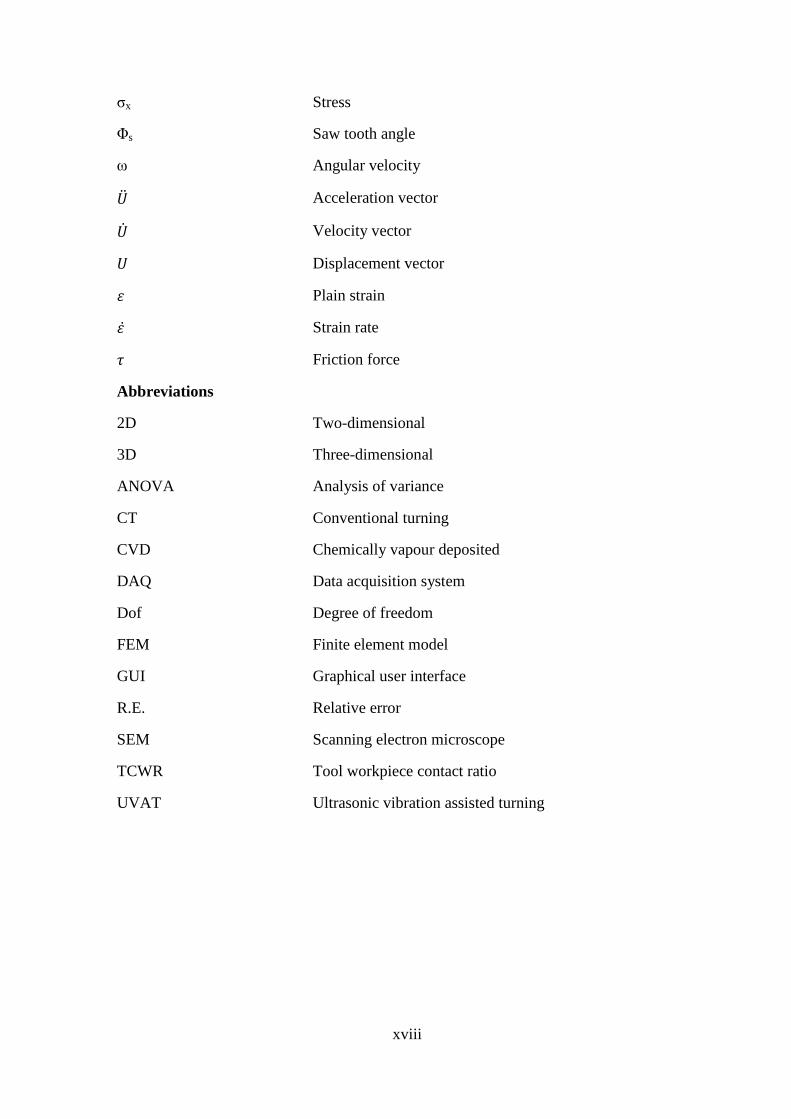
Abbreviations
2D Two-dimensional
3D Three-dimensional
ANOVA Analysis of variance
CT Conventional turning
CVD Chemically vapour deposited
DAQ Data acquisition system
Dof Degree of freedom
FEM Finite element model
GUI Graphical user interface
R.E. Relative error
SEM Scanning electron microscope
TCWR Tool workpiece contact ratio
UVAT Ultrasonic vibration assisted turning

1
Chapter 1
Introduction Advancement of science and innovation, improvement of modern creations and
requirement of finished products with quality components are increasing day by day.
Additionally, the final products should have possessed extraordinary properties like high
strength, hardness, and corrosion resistance. To meet these needs, there is a rapid
evolution of new materials and alloys like non-ferrous alloys, brittle and hard materials,
and ceramic structures. Machining of these hard materials produces challenges like high
cutting force, low tool life with an average surface quality. Turning operation has been
extensively used as a material removal process in each industry. Therefore, industries are
continuously asking and implementing novel machining methods. The ultrasonic vibration
assisted turning (UVAT), in particular, is one of the novel innovations. It has been
observed that the vibration assisted turning enhances the machinability of these difficult to
cut materials reducing the cutting force, enhancing the tool life with an improved
machined surface. Additionally, ultrasonic vibration assisted machining has a broad range
of application and importance in the field of automobile, electronic industry, aerospace,
marine, and biomedical industries. The present research has been carried out investigating
the machinability of titanium alloy, Ti-6Al-4V using UVAT.
1.1 Titanium Alloys
The machining of Titanium alloys has got an extensive attention from industries like
aerospace, medical, and biomedical plants, etc. due to its unique properties like light
weight, high strength, high corrosion resistance and high strength to weight ratio. The
application details [1-6] of this alloy are given in Table 1.1.
Despite these advantages, there arise several difficulties during the machining process
of titanium alloys due to its inherent properties like high strength at elevated temperature,
affinity to react with the tool and reduced thermal conductivity. These challenges in
machining process make the titanium alloy as intractable or ―hard to cut‖ alloy.
Chapter 1 Introduction
2
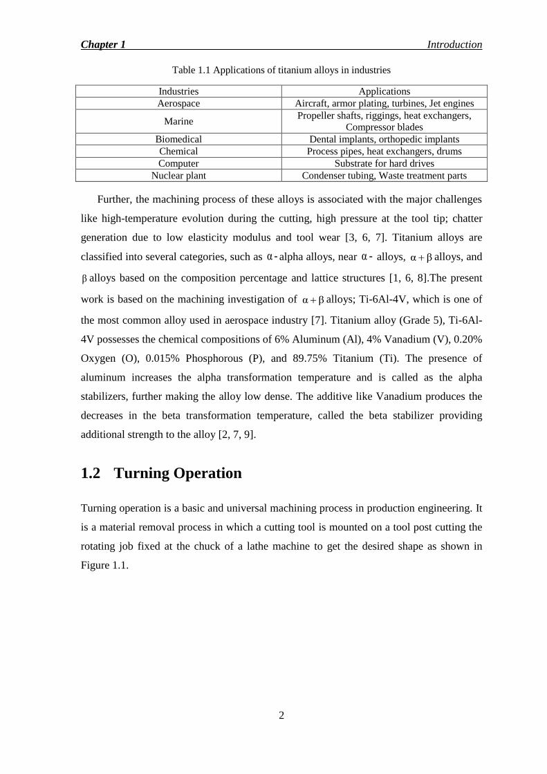
Table 1.1 Applications of titanium alloys in industries
Industries Applications
Aerospace Aircraft, armor plating, turbines, Jet engines
Marine Propeller shafts, riggings, heat exchangers,
Compressor blades
Biomedical Dental implants, orthopedic implants
Chemical Process pipes, heat exchangers, drums
Computer Substrate for hard drives
Nuclear plant Condenser tubing, Waste treatment parts
Further, the machining process of these alloys is associated with the major challenges
like high-temperature evolution during the cutting, high pressure at the tool tip; chatter
generation due to low elasticity modulus and tool wear [3, 6, 7]. Titanium alloys are
classified into several categories, such as -α alpha alloys, near -α alloys, βα alloys, and
β alloys based on the composition percentage and lattice structures [1, 6, 8].The present
work is based on the machining investigation of βα alloys; Ti-6Al-4V, which is one of
the most common alloy used in aerospace industry [7]. Titanium alloy (Grade 5), Ti-6Al-
4V possesses the chemical compositions of 6% Aluminum (Al), 4% Vanadium (V), 0.20%
Oxygen (O), 0.015% Phosphorous (P), and 89.75% Titanium (Ti). The presence of
aluminum increases the alpha transformation temperature and is called as the alpha
stabilizers, further making the alloy low dense. The additive like Vanadium produces the
decreases in the beta transformation temperature, called the beta stabilizer providing
additional strength to the alloy [2, 7, 9].
1.2 Turning Operation
Turning operation is a basic and universal machining process in production engineering. It
is a material removal process in which a cutting tool is mounted on a tool post cutting the
rotating job fixed at the chuck of a lathe machine to get the desired shape as shown in
Figure 1.1.

Chapter 1 Introduction
3
Figure 1.1 Line diagram for Lathe
Moreover, the introduction of metals and alloys with high hardness gradually required
novel machining process mainly due to the high cost of hard cutting tools. So, several new
machining processes were investigated and introduced to the turning process, such as hot
turning, high-speed turning, turning with the cryogenically treated cutting tool, ultrasonic
vibration assisted turning, thermally enhanced ultrasonic vibration assisted turning, laser
assisted turning, and plasma assisted turning, etc. [10-18]. The present work is more
focused to the ultrasonic vibration assisted turning.
1.2.1 Conventional turning (CT)
The conventional turning has been found to be very challenging work to process the
intractable or ―hard to cut‖ alloys. The inherent properties of Ti-6Al-4V like reduced
thermal conductivity, work hardening, high hardness at elevated temperature and affinity
to react with the workpiece limit its machining process. Therefore, there is a need for an
alternative machining method to process these alloys and ultrasonic vibration assisted
turning is one of the novel methods to process these alloys.
Chapter 1 Introduction
4
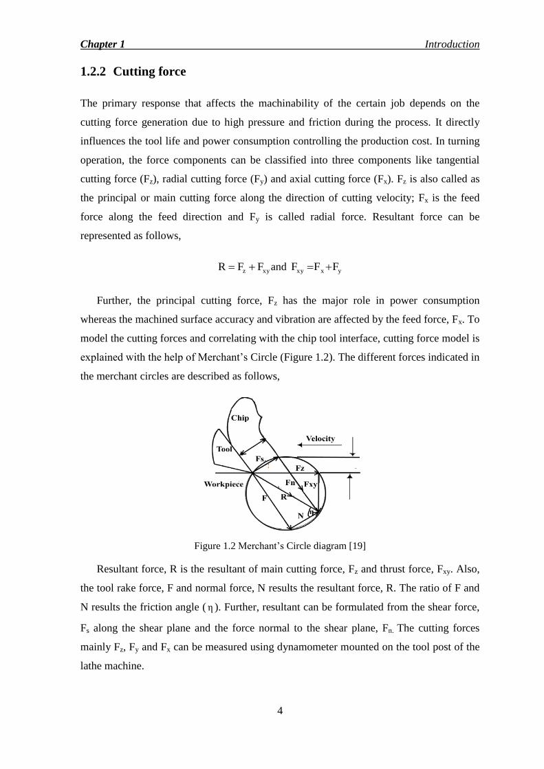
1.2.2 Cutting force
The primary response that affects the machinability of the certain job depends on the
cutting force generation due to high pressure and friction during the process. It directly
influences the tool life and power consumption controlling the production cost. In turning
operation, the force components can be classified into three components like tangential
cutting force (Fz), radial cutting force (Fy) and axial cutting force (Fx). Fz is also called as
the principal or main cutting force along the direction of cutting velocity; Fx is the feed
force along the feed direction and Fy is called radial force. Resultant force can be
represented as follows,
xyz FFR and yxxy FFF
Further, the principal cutting force, Fz has the major role in power consumption
whereas the machined surface accuracy and vibration are affected by the feed force, Fx. To
model the cutting forces and correlating with the chip tool interface, cutting force model is
explained with the help of Merchant‘s Circle (Figure 1.2). The different forces indicated in
the merchant circles are described as follows,
Figure 1.2 Merchant‘s Circle diagram [19]
Resultant force, R is the resultant of main cutting force, Fz and thrust force, Fxy. Also,
the tool rake force, F and normal force, N results the resultant force, R. The ratio of F and
N results the friction angle ( η ). Further, resultant can be formulated from the shear force,
Fs along the shear plane and the force normal to the shear plane, Fn. The cutting forces
mainly Fz, Fy and Fx can be measured using dynamometer mounted on the tool post of the
lathe machine.
Chapter 1 Introduction
5
1.2.3 Cutting temperature
Temperature evolution during turning operation is due to the friction between the tool and
workpiece or chip surface, has a direct effect on the tool wear. Therefore, temperature
measurement or prediction of interface temperature has always been a challenging task for
the researchers. As far as thermal effects are concerned, cutting temperature distribution is
a most desired factor which needs to be accurately predicted to analyze wear rate, tool life,
thermal stress and tool chipping in order to identify the optimum cutting conditions, tool
design, and coating to improve the cutting capability. Some researchers investigated the
cutting temperature during conventional turning using the photographic technique,
embedded thermocouples, high speed thermal video camera and a high resolution
thermographic system and also using some innovative methods like the inverse procedure
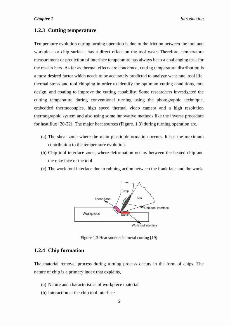
for heat flux [20-22]. The major heat sources (Figure. 1.3) during turning operation are,
(a) The shear zone where the main plastic deformation occurs. It has the maximum
contribution to the temperature evolution.
(b) Chip tool interface zone, where deformation occurs between the heated chip and
the rake face of the tool
(c) The work-tool interface due to rubbing action between the flank face and the work.
Figure 1.3 Heat sources in metal cutting [19]
1.2.4 Chip formation
The material removal process during turning process occurs in the form of chips. The
nature of chip is a primary index that explains,
(a) Nature and characteristics of workpiece material
(b) Interaction at the chip tool interface
Chapter 1 Introduction
6
(c) Specific energy
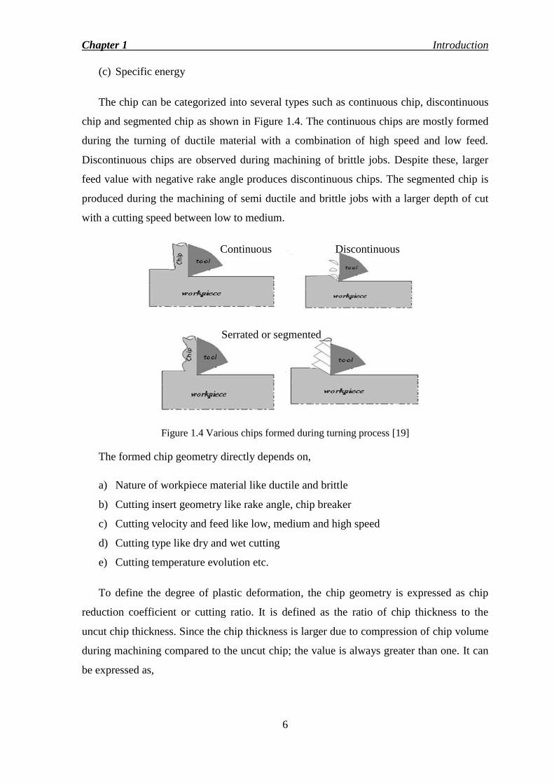
The chip can be categorized into several types such as continuous chip, discontinuous
chip and segmented chip as shown in Figure 1.4. The continuous chips are mostly formed
during the turning of ductile material with a combination of high speed and low feed.
Discontinuous chips are observed during machining of brittle jobs. Despite these, larger
feed value with negative rake angle produces discontinuous chips. The segmented chip is
produced during the machining of semi ductile and brittle jobs with a larger depth of cut
with a cutting speed between low to medium.
Figure 1.4 Various chips formed during turning process [19]
The formed chip geometry directly depends on,
a) Nature of workpiece material like ductile and brittle
b) Cutting insert geometry like rake angle, chip breaker
c) Cutting velocity and feed like low, medium and high speed
d) Cutting type like dry and wet cutting
e) Cutting temperature evolution etc.
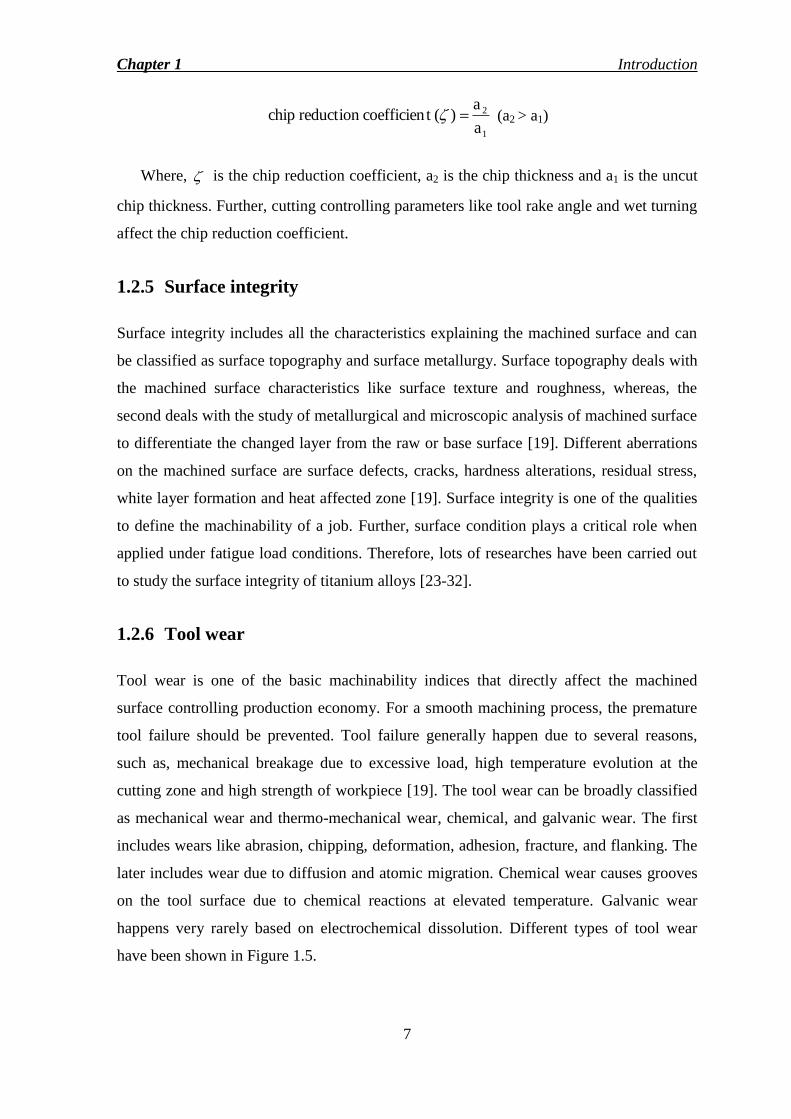
To define the degree of plastic deformation, the chip geometry is expressed as chip
reduction coefficient or cutting ratio. It is defined as the ratio of chip thickness to the
uncut chip thickness. Since the chip thickness is larger due to compression of chip volume
during machining compared to the uncut chip; the value is always greater than one. It can
be expressed as,
Continuous Discontinuous
Serrated or segmented
Chapter 1 Introduction
7
1
2
a
a )(t coefficienreduction chip (a2 > a1)
Where, is the chip reduction coefficient, a2 is the chip thickness and a1 is the uncut
chip thickness. Further, cutting controlling parameters like tool rake angle and wet turning
affect the chip reduction coefficient.
1.2.5 Surface integrity
Surface integrity includes all the characteristics explaining the machined surface and can
be classified as surface topography and surface metallurgy. Surface topography deals with
the machined surface characteristics like surface texture and roughness, whereas, the
second deals with the study of metallurgical and microscopic analysis of machined surface
to differentiate the changed layer from the raw or base surface [19]. Different aberrations
on the machined surface are surface defects, cracks, hardness alterations, residual stress,
white layer formation and heat affected zone [19]. Surface integrity is one of the qualities
to define the machinability of a job. Further, surface condition plays a critical role when
applied under fatigue load conditions. Therefore, lots of researches have been carried out
to study the surface integrity of titanium alloys [23-32].
1.2.6 Tool wear
Tool wear is one of the basic machinability indices that directly affect the machined
surface controlling production economy. For a smooth machining process, the premature
tool failure should be prevented. Tool failure generally happen due to several reasons,
such as, mechanical breakage due to excessive load, high temperature evolution at the
cutting zone and high strength of workpiece [19]. The tool wear can be broadly classified
as mechanical wear and thermo-mechanical wear, chemical, and galvanic wear. The first
includes wears like abrasion, chipping, deformation, adhesion, fracture, and flanking. The
later includes wear due to diffusion and atomic migration. Chemical wear causes grooves
on the tool surface due to chemical reactions at elevated temperature. Galvanic wear
happens very rarely based on electrochemical dissolution. Different types of tool wear
have been shown in Figure 1.5.

Chapter 1 Introduction
8
Figure 1.5 Tool wear region [33]
1.2.7 Ultrasonic vibration assisted turning (UVAT)
Ultrasonic vibration assisted turning is an innovative method to process the hard to cut
alloys in which the cutting insert is subjected to a very high-frequency vibration, 20 kHz
with a small amplitude. It has several advantages over conventional turning such as
reduction in cutting forces with an improved machined surface and enhancing the tool life
[18]. Ultrasonic vibration machining process was first introduced during the 1960s in
which the vibration was applied onto the cutting tool with the help of a hydraulic vibrator
with a vibration frequency range of 0-125 Hz [34]. Considering the turning operation and
direction of vibration, it can be categorized into three parts as shown in Figure 1.6.
UVAT with cutting insert vibrating in tangential direction
UVAT with cutting insert vibrating in radial or depth of cut direction
UVAT with cutting insert vibrating in axial or feed direction
Figure 1.6 Different types of cutting vibrations in UVAT
Chapter 1 Introduction
9
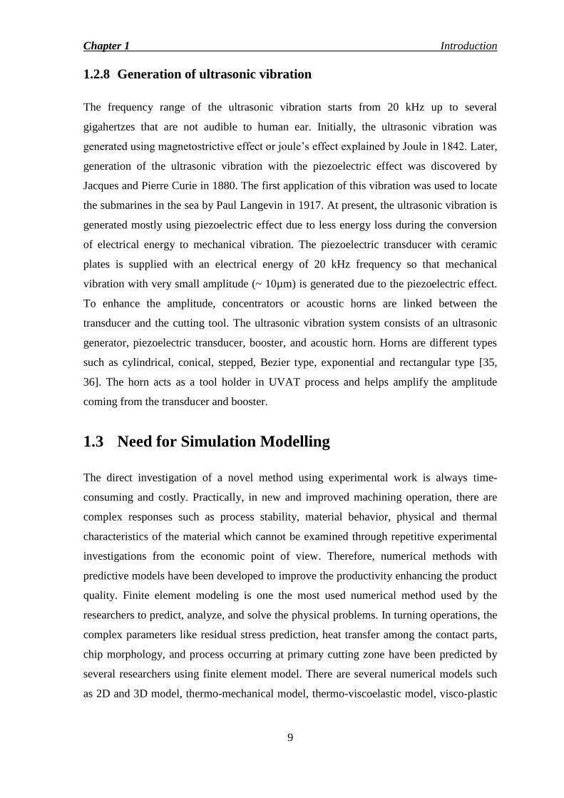
1.2.8 Generation of ultrasonic vibration
The frequency range of the ultrasonic vibration starts from 20 kHz up to several
gigahertzes that are not audible to human ear. Initially, the ultrasonic vibration was
generated using magnetostrictive effect or joule‘s effect explained by Joule in 1842. Later,
generation of the ultrasonic vibration with the piezoelectric effect was discovered by
Jacques and Pierre Curie in 1880. The first application of this vibration was used to locate
the submarines in the sea by Paul Langevin in 1917. At present, the ultrasonic vibration is
generated mostly using piezoelectric effect due to less energy loss during the conversion
of electrical energy to mechanical vibration. The piezoelectric transducer with ceramic
plates is supplied with an electrical energy of 20 kHz frequency so that mechanical
vibration with very small amplitude (~ 10µm) is generated due to the piezoelectric effect.
To enhance the amplitude, concentrators or acoustic horns are linked between the
transducer and the cutting tool. The ultrasonic vibration system consists of an ultrasonic
generator, piezoelectric transducer, booster, and acoustic horn. Horns are different types
such as cylindrical, conical, stepped, Bezier type, exponential and rectangular type [35,
36]. The horn acts as a tool holder in UVAT process and helps amplify the amplitude
coming from the transducer and booster.
1.3 Need for Simulation Modelling
The direct investigation of a novel method using experimental work is always time-
consuming and costly. Practically, in new and improved machining operation, there are
complex responses such as process stability, material behavior, physical and thermal
characteristics of the material which cannot be examined through repetitive experimental
investigations from the economic point of view. Therefore, numerical methods with
predictive models have been developed to improve the productivity enhancing the product
quality. Finite element modeling is one the most used numerical method used by the
researchers to predict, analyze, and solve the physical problems. In turning operations, the
complex parameters like residual stress prediction, heat transfer among the contact parts,
chip morphology, and process occurring at primary cutting zone have been predicted by
several researchers using finite element model. There are several numerical models such
as 2D and 3D model, thermo-mechanical model, thermo-viscoelastic model, visco-plastic

Chapter 1 Introduction
10
model, thermo-elastic plastic model, rigid-plastic model, Eulerian model, and ALE
(Arbitrary Lagrangian Eulerian) model, etc. [37].
1.4 Motivation for the Present Research
There has been a growing demand in industries for new alloys with outstanding
characteristics like light weight with high strength, corrosion resistance, and superior
elasticity. Titanium alloy, Ti-6Al-4V is one of the alloys that extensively used in
aerospace industries, marine, biomedical and oil industries. Still, due to properties like
reduced thermal conductivity and high hardness at elevated temperature, the machining of
this alloy has been a promising and challenging task using conventional methods.
Ultrasonic vibration assisted turning is one of the novel machining process enhancing the
machinability of these hard to cut alloy significantly reducing cutting forces with an
improved machined surface and enhancing the tool life. Therefore, it is essential to
investigate the machinability of these alloys during the ultrasonic vibration assisted
turning. Unlike conventional turning models for this alloy, there are very few numerical
models developed for the present process using this alloy.
Ample studies were made to find an optimum geometry of the concentrators or horns
since the advantages of an ultrasonic vibration assisted turning are more prominent at a
higher amplitude. Inversely, there is a heating problem as the amplitude increases. Past
research says horns like stepped type and Bezier type have higher amplification compared
to the other types. Therefore, it is essential to find out an innovative and flexible acoustic
horn with higher amplification factor having flexible attachments for the economic point
of view.
1.5 Aim and Objectives of the Present Work
The primary aim of the present research is to investigate the machinability of hard to cut
titanium alloy, Ti-6Al-4V using ultrasonic vibration assisted turning. To fulfill the above
target, the objectives are as follows:
1. Design and modeling of a flexible acoustic horn for the ultrasonic vibration
assisted turning with finite element method (Performing modal and harmonic
analysis) using an available academic package of Ansys v 15®.

Chapter 1 Introduction
11
2. Fabrication of the same based on the results obtained from the numerical analysis.
3. 3D finite element modeling of ultrasonic assisted turning for Ti-6Al-4V
investigating process parameters and predicting various output responses like the
transient behavior of stress, effective strain, interface temperature etc.
4. Experimental investigation of ultrasonic vibration assisted turning to study various
effects of process parameters on the output responses.
5. Comparison of output responses (Cutting force, roughness, tool temperature etc.)
obtained during ultrasonic vibration assisted turning with the conventional results
6. Model validation comparing the numerical results with the measured results
7. Investigation of machinability indices like chip morphology, surface integrity, tool
wear.
1.6 Thesis Organization
There are seven chapters in the present work as follows,
Chapter 1- Introduction
It describes the application of hard to cut alloys like Ti-6Al-4V within various industries
along with its properties. It covers a brief summary of conventional turning process and
the need of novel technique, ultrasonic vibration assisted turning to process these alloys.
Further, it explains few machinability indices along with various terminology related to
turning operation.
Chapter 2- Literature review
It provides in-depth surveys related to turning process of titanium alloys, conventional
turning, and ultrasonic vibration assisted turning, finite element modeling, machinability
indices like chip morphology, surface integrity and tool wear. Moreover, this chapter helps
to provide information emphasizing the need of present work.
Chapter 3- Design, modeling, and fabrication of acoustic horn
It explains different types of acoustic horns used for ultrasonic assisted manufacturing
process. It includes design and modeling of a flexible acoustic horn for ultrasonic
vibration assisted turning using finite element model.
Chapter 1 Introduction
12
Chapter 4- Experimental investigations
This chapter covers experimental design along with the experimental results for both the
cutting operation. It explains the effects of cutting parameters on the output responses like
force, tool temperature, and surface roughness. Further, it has a comparative analysis of
machinability indices for both the cutting processes.
Chapter 5- Numerical Modelling and Comparison of Results
It explains modeling of the cutting processes using finite element model using commercial
package, Deform 3D®. It covers the predicted results obtained from the simulation.
Further, it includes the model validation comparing the results with the experimental
results.
Chapter 6- Chip Morphology, Tool Wear, and Surface Integrity Investigations
It includes investigations of machinability indices like chip morphology, tool wear, and
surface roughness. Chip morphology includes chip reduction coefficient, chip
segmentation frequency. Tool wear includes both the flank and crater wears due to CT and
UVAT.
Chapter 7- Conclusions
It contains major findings for the ultrasonic vibration assisted turning comparing with the
conventional turning for both measured and numerical results. Also, it explains several
works that needs to be done in the future to enhance the cutting process during ultrasonic
vibration assisted turning. Finally, the work is enclosed with the list of references.
1.7 Closure
The present chapter discusses the importance of titanium alloys in different industries and
their limitations during machining using conventional methods. The background of
turning process with terminology related to it has been discussed. Moreover, the need of a
novel machining process like ultrasonic vibration assisted turning and its applications have
been examined. This chapter also explains the motivation and objectives of the present
investigation.

13
Chapter 2
Literature Review The motivation behind the literature review is to give foundation data on the issues to be
considered in the present work and underscore the significance of the present study. The
literature review extensively discusses the research works on the machining of titanium
alloys, particularly Ti-6Al-4V with its demanding applications in various industries. The
need of novel machining processes like ultrasonic vibration assisted turning to improve
the machinability of this hard to cut alloys have been presented.
Turning operation is a standout amongst the most widely utilized material removal
procedures, and its innovation keeps on progressing in parallel with the advancements in
material science. The productivity and efficiency of a machining process depend on the
cutting control parameters, environmental conditions, experimental apparatus, and
workpiece and tool characteristics [38]. The ease with which a machining operation of
material is carried out is called the machinability of that material. Prime machinability
indices that affect the productivity and economy are surface roughness, cutting force, chip
morphology, and tool wear [11, 39].
2.1 Turning of Titanium Alloys
Demand for new and special alloys in present industries has created advanced engineering
materials and alloys with superior strength, outstanding corrosion and wear resistance with
low weight to strength. Titanium alloys are used extensively in industries like aerospace,
biomedical plants, turbocharger and turbine making plants [1, 4, 5, 9, 11, 39, 40]. But,
properties like reduced thermal conductivity and high strength at an elevated temperature
causing high tool temperature leading to fast tool wear rate and work hardening, make it
an intractable or ‗hard to cut‘ alloy [7, 9, 41-44]. The major challenges faced by
researchers during the machining of these alloys are the short tool life with average
surface finish due to the poor machinability. The reduced thermal conductivity and high
hardness at elevated temperature result very high temperature evolution at the tool
workpiece interface affecting the machinability in a negative way [44, 45].

Chapter 2 Literature Review
14
The major problem in machining of titanium alloy is the tool wear due to high
chemical reactive nature of the titanium towards the cutting tool resulting in the generation
of build-up edges and high cutting force. Bhaumik et al. [41] investigated the turning
operation of Ti-6Al-4V alloy using wBN-cBN composite tools. He suggested these cutting
tools economically viable to process the hard to cut alloys. Machado et al. [2] studied
different machinability indices like chip formation, tool wear and wear mechanism in
turning of titanium and titanium alloys. Further, due to unavoidable challenges, the
authors tried few novel machining processes like ultrasonic vibration assisted turning
using rotary and ledge tools. Che-Haron et al. [46] studied the nature of both coated and
uncoated cutting insert during the machining of titanium alloys. He concluded that the
insert with finer grain size helped the machinability of these alloy enhancing the tool life
with a better surface finish. Further, he noted that flank wear and excessive chipping at the
flank wear were the prime cause of the tool wear. Ezugwu et al. [40] experimented using
various cutting tools on the aerospace alloys for different cutting velocity ranges. He
suggested for low speed cutting, cemented carbides (including coated carbides), ceramic
tools and CBN tools could be the best suited insert to process the hard to cut alloys. For
turning with high speed, CBN and ceramic tools can be the most economic insert for
continuous machining of aerospace alloys. Further, researchers made special cutting tools
to avoid the tool wear problem during the turning of Ti-6Al-4V [47]. Cemented carbide
insert with 10% weight percentage of Ni3Al was prepared with the help of spark plasma
sintering method, and it showed significant resistance to flank and rake face wear.
Che- Haron et al. [26] carried out a dry turning operation of Ti-6Al-4V using uncoated
carbide tool. The major findings were surface finish, microhardness of the machined
surface and the metallographic study of the machined surface layer. He found that the
surface roughness is significantly high due to the reduced thermal conductivity of the
insert resulting severe tool wear. The machined surface was found with alteration of the
microstructure along with a white layer of thickness 10 µm. Therefore, the machining of
the intractable alloy was found to be a challenging task in the conventional machining.
Ramesh et al. [31] analyzed the surface roughness obtained during the machining of Ti-
6Al-4V with a multi-layered cutting insert and formulated it by means of ANOVA
(Analysis of Variance). He found that the feed was the prime factor affecting surface
roughness. Surface roughness increased to the maximum as the feed increased to a
specific limit. The authors used a statistical method, response surface methodology (RSM)

Chapter 2 Literature Review
15
to design the experiment and prepare a regression equation for the prediction purpose.
Further, Chauhan et al. [48] examined the effect of cutting control parameters on the
surface roughness while cutting Ti-6Al-4V with a polycrystalline diamond (PCD) with the
RSM design. He observed that the feed, speed, and approach angle were the most
influential factors affecting the surface roughness. As approach angle increases, there was
an improvement in the machined surface. Ramesh et al. [49] studied the chip morphology
and surface roughness while turning Ti-6Al-4V using a coated round insert, RCMT
10T300 using response surface methodology. Satyanarayana et al. [50] investigated the
significance of back rake angle on the cutting force and surface roughness using Taguchi
grey method during the turning of Ti-6Al-4V. Surface roughness characteristics depending
on the various cutting control parameters like cutting velocity, feed and approach angle
during turning of Ti-6Al-4V using coated insert were studied by Sharma et al. [51] and
optimum parameters were identified. To achieve a sustainable turning operation of
titanium alloy, Ti-6Al-4V, different types of lubricants such as cryogenic type, minimum
quality lubrication (MQL), minimum quality cooled lubrication (MQCL) were used to
reduce the friction coefficient [52]. Among these lubrications, MQL and MQCL with
vegetable oils gave comparably acceptable results. Lin et al. [53] investigated the turning
of Ti-6Al-4V using MQL to minimize the cost and pollution due to conventional cooling.
Further, to increase the machinability of titanium alloy, Ti-6Al-4V in turning operation,
researchers used lubricants with solid and suspended particles like graphite and
molybdenum particles [54]. It was observed that cutting indices like tool wear, surface
roughness, interface temperature and tool wear were marginally reduced on the application
of lubricant with solid particles.
Venugopal et al. [12] studied the experimental investigation of Ti-6AL-4V using
cryogenic liquid nitrogen as coolant. Since the high temperature evolution at the tool
workpiece interface is the main reason for the wear propagation; the author used liquid
nitrogen to increase the hardness of an ISO K20 grade cutting insert. Significant
reductions in tool wear like adhesion, diffusion, and flank wear were observed at the end
of the experiment. Moreover, Dhananchezian et al. [55] carried out turning of Ti-6Al-4V
using a cryogenically cooled cutting insert and concluded that it significantly reduces the
wear on the flank and rake surfaces along with the temperature reduction. Some
researchers studied the machining of Ti-6Al-4V alloy obtained from the Electron beam
melting technology (EBM) abundantly used in biomedical implants using coated insert

Chapter 2 Literature Review
16
with dry and cryogenic lubricant [56]. The cryogenic cooling significantly reduced the
adhesive wear reducing the machinability issues. Further, to enhance the machinability of
Ti-6Al-4V, Nandy et al. [57] made an experimental set up with high pressure coolant jet
that directly affected the cutting zone. He investigated several output responses like
cutting force, chip morphology, tool life, and surface roughness. Unlike low pressure
coolant, the high pressure coolant jet was more beneficial in reducing the cutting forces,
improving the surface finish and tool wear. The similar type of experiment was carried out
by Palanisamy et al. [58] during the turning of Ti-6Al-4V and found that the high pressure
coolant enhanced the tool life with a better surface finish. Also, the application of high
pressure coolant increased the chip serration frequency with higher strain rate.
Additionally, to reduce the friction between the workpiece and tool for low temperature
evolution, experiments were performed using micro- grooved cutting inserts [59]. Micro-
grooved tool helps decrease the cutting force and temperature significantly. Additionally,
Ma et al. [60] investigated the performance of micro-grooved tool while turning Ti-6Al-
4V to reduce the cutting force and energy consumptions. Daymi et al. [61] studied the
effect of cutting velocity on the chip morphology and force generation while cutting Ti-
6Al-4V using a multi-layered coated insert. For different ranges of velocities, there were
alternations in the chip geometries, such as continuous chip, flow chip, and segmented
chips were obtained at 50 m/min, 100 m/min, and 150 m/min respectively. Moreover, the
shear bands were more prominent during the high speed turning operation due to strain
localization and high temperature generation. The force value was significantly reduced as
the velocity increases from low to high cutting velocity. Cotterell et al. [62] formulated a
thermal model numerically to understand the process occurring at the chip tool interface
and rake face. Also, he examined the chip morphology and observed segmented chips for
all possible runs varying the cutting velocity. The heat generation and tool temperature
evolution on the rake face with the help of chip shape and chip color during turning of Ti-
6Al-4V with dry and minimum quality lubrication (MQL) was experimented and
predicted [63]. The chip formed during MQL was found to be more curled and white in
color showing less heat generation. Dandekar et al. [44] investigated a hybrid machining
process to improve the machinability of Ti-6AL-4V using coated tool. The experiment
was a hybrid machining in which the hardness of the material was reduced using the laser
impingement. He concluded that the hybrid machining process improved the
machinability at the high range of cutting velocity enhancing the material removal rate,
tool life, and surface finish. So, there has been a need for a new machining process to
Chapter 2 Literature Review
17
increase the productivity while processing the titanium alloys. An et al. [64] studied on the
turning of titanium alloy using cold water mist jet (CWMJ) instead of conventional
lubrication to avoid the unwanted high temperature evolution during the turning operation.
He concluded that the temperature and tool wear were drastically reduced during the use
of CWMJ. Turning of titanium alloy, Ti-6Al-4V with ultra-hard cutting inserts like
polycrystalline cubic boron nitride (PCBN) and polycrystalline diamond (PCD) were used
to study the tool wear, temperature, surface roughness and microhardness.
2.2 Ultrasonic Vibration Assisted Turning (UVAT)
Due to rapid industrialization, there has been a growing demand for new and special
material like super alloys and structural ceramics with unique properties like high strength,
excellent corrosion resistance, and low weight to strength ratio. Therefore, researchers
have been extensively exploring on new and novel machining methods to enhance the
productivity along with the production economy. The ultrasonic vibration assisted turning
(UVAT) is one of the novel machining method to process these intractable alloys in which
very high frequency of 20 kHz with a small amplitude of 10 µm is imposed on the cutting
tool with the help of an ultrasonic arrangement [65]. There is an extensive research in this
field due to several advantages while machining using this method, such as reduction in
cutting forces, enhancement of tool life, improved surface finish, and high material
removal rate.
Initially, the vibration cutting was carried out by Kumabe [66] in which vibration was
applied to the cutting tool to stabilize the cutting force characteristics during the turning
operation. Further, the vibration assisted machining was studied by Kumabe and
Hachisuka [67] observed an improved surface finish during the turning of plain carbon
steels, stainless steel, and hardened steels. It has been reported that the material removal
process was found to be marginally high while turning of ceramics [68]. The importance
and advantages of vibration assisted turning were explained by Frederick [69]. The
assessments revealed that the superposition of vibration onto the tool helped to reduce the
cutting force with reduction in tool wear. Skelton et al. [34] allowed oscillation to the
cutting tool in the tangential direction by means of a hydraulic vibrator during the turning
process and marginally reduction in forces were observed. Zhou et al. [70] carried out
turning of brittle material, fused silica applying ultrasonic vibration to a diamond cutting
Chapter 2 Literature Review
18
tool. The reduction in cutting force and surface roughness was observed during low
cutting velocity comparing with the conventional turning. Astashev [71] prepared a model
for ultrasonic vibration assisted cutting with working frequency of 20 kHz and amplitude
of 10 microns. He found significant reduction in cutting forces. He explained that the
reduction in cutting forces depends on the cutting velocity and after a critical cutting
velocity; there will be no advantages of vibration assisted turning. Additionally, a
theoretical model along with the experimental investigation of the process superimposing
vibration on the cutting tool was studied. Various dynamic characteristics like force
reduction and material removal rate were studied along with a brief explanation of the
stabilization of ultrasonic excitation. Kim et al. [72] investigated the machinability of
highly demanding composite, CFRP (carbon fiber reinforced plastics) using ultrasonic
vibration cutting (UVC). He observed that UVC helped the machinability with a cutting
velocity within the range of critical velocity. Further, cutting velocity and feed were the
most controllable parameters affecting the reduction of force and surface roughness.
For last decades, there were researches works carried out by several researchers on this
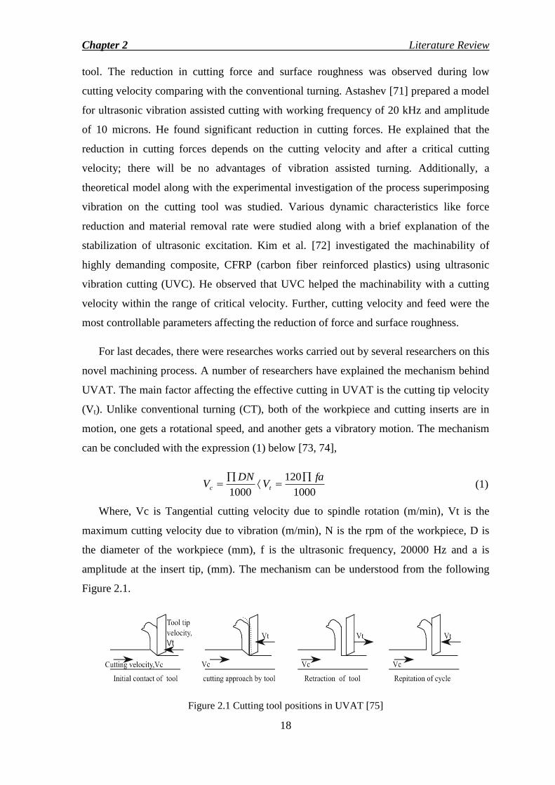
novel machining process. A number of researchers have explained the mechanism behind
UVAT. The main factor affecting the effective cutting in UVAT is the cutting tip velocity
(Vt). Unlike conventional turning (CT), both of the workpiece and cutting inserts are in
motion, one gets a rotational speed, and another gets a vibratory motion. The mechanism
can be concluded with the expression (1) below [73, 74],
1000
120
1000
faV
DNV tc
(1)
Where, Vc is Tangential cutting velocity due to spindle rotation (m/min), Vt is the
maximum cutting velocity due to vibration (m/min), N is the rpm of the workpiece, D is
the diameter of the workpiece (mm), f is the ultrasonic frequency, 20000 Hz and a is
amplitude at the insert tip, (mm). The mechanism can be understood from the following
Figure 2.1.
Figure 2.1 Cutting tool positions in UVAT [75]
Chapter 2 Literature Review
19
Babitsky et al. [76] applied ultrasonic assisted turning on aviation materials like C263,
Inconel 718 and mild steel with an ultrasonic vibration along the feed direction. The
roughness and roundness of UVAT and CT machined workpiece were compared. The
machined surface during vibration assisted turning was more improved than the
conventional turning. Further, the chip formed during UVAT process was continuous
without formation of built-up edges (BUE). To keep the vibration excitation stable during
the turning operation, an innovative auto resonant set up was established. Further,
experimental investigation and numerical simulations of both conventional turning and
ultrasonic assisted turning were carried out to analyze the process occurring at the chip
tool interface using MSC MARC® [73]. A numerical simulation model was validated with
the experimental results explaining various stages of ultrasonic assisted turning, such as
(a) approaching stage (b) penetration stage (c) unloading stage, and (d) withdrawal stage.
Mitrofanov et al. [77] studied overall reductions in cutting forces, temperature
distribution, residual stress and microhardness of surface layer . A thermo-mechanical
model for ultrasonic assisted turning of Inconel 718 was prepared to investigate the tool
temperature and interface temperature evaluation [78]. Also, the effect of heat transfer
coefficient on the temperature evolution was discussed. Finite element model was
developed for ultrasonic assisted turning using MSC MARC® to study the effect of cutting
parameters like velocity, feed and depth of cut and lubrication type on the chip formation,
forces, temperature distribution, and strain rate [79]. Plastic strain is found to be almost
15-20% high in case of ultrasonic assisted turning with a high material removal rate
compared to the conventional turning. N Ahmed et al. [80] studied material responses like
hardness, residual stress and change in microstructure during the machining of Inconel
718 . The average hardness of the surface using the ultrasonic assisted turning was 60%
less than the conventional turning with a high value of residual stress. The simulation
modelling using MSC-MARC® and analysis of ultrasonic vibration assisted turning of
Inconel 718 were made by S. Amini [81]. He concluded that the cutting force depends on
the cutting velocity and increases with increase in the latter. The effect of tool geometry
on the UVAT process was quite similar to conventional turning. The increase in the
amplitude of vibration resulted in significant reduction in cutting force during UVAT.
Ahmed et al. [74] investigated the effect of turning and vibration parameters like cutting
velocity, feed, amplitude, frequency, and direction of vibration on the cutting forces . He
explained that the reduction of force with increase in amplitude and frequency was due to
the increased cycle between the workpiece and tool during the intermittent motion of
Chapter 2 Literature Review
20
cutting tool. Nath et al. [82, 83] carried out several experimental and theoretical
investigations on ultrasonic vibration cutting of low alloys steel and Inconel 718. They
claimed that to improve the quality of cutting, the tool workpiece contact ratio (TWCR)
should be kept low. The major advantages of ultrasonic assisted turning were reduction in
cutting forces, flank wear (12-25% reduction compared to CT) and improved surface
quality. Further, they observed that at high cutting speed, there were catastrophic failures
on the tool face due to impact loading of repeated vibrations. Also, the chip formed during
UVAT was smooth, thin, and more curled than the chip formed during CT. Further, the
authors studied on the elliptical vibration cutting to enhance the machinability of hard to
cut alloys. The effect of cutting parameters like velocity, feed, depth of cut and nose
radius on the output responses like force, surface roughness, and tool wear were
investigated [84, 85].
Several researchers investigated the machinability of titanium alloys during ultrasonic
vibration assisted turning. S. Koshimizu [86] assessed the ultrasonic vibration assisted
turning (UVAT) of titanium alloy, Ti-6Al-4V and concluded that the UVAT was the most
alternative process to reduce the force, tool wear, and surface roughness. The author
mentioned that the UVAT is more effective when the cutting velocity is approximately
30% of the critical velocity. Muhammad et al. [87] studied the 3D finite element model for
ultrasonic assisted oblique cutting of titanium alloy, Ti15V3Cr3Al3Sn. The research
mainly adhered to the effect of cutting parameters like frequency, amplitude and contact
conditions like with friction and without friction on the cutting forces only. Further, they
carried out few hybrid machining processes like hot ultrasonically assisted turning or
thermally enhanced ultrasonically assisted turning [15, 88-91]. They concluded that the
material removal rate was comparatively high with an improved surface finish comparing
with normal vibration assisted turning. Additionally, the authors prepared a thermo-
mechanical model to predict the processes occurring at the chip tool interface, stress
generation, and interface temperature. Patil et al. [92] assessed ultrasonic assisted turning
of Ti-6Al-4V and concluded that cutting force increased due to increase in the cutting
velocity. The machined surface obtained during UVAT was more improved compared to
the CT machined surface. The metallographic study revealed that the microstructure of
machined surface during UVAT was less deformed. Also, the chip produced during
UVAT was more uniform, smooth, and thinner making this process superior than CT.
Chapter 2 Literature Review
21
Nategh et al. [93] analyzed the hardness of lateral surface in oblique ultrasonic
vibration assisted turning. He justified the effect of amplitude and cutting velocity on the
ultrasonic assisted turning. UVAT will be more effective for higher amplitude and lower
cutting velocity. A mechanistic friction model was prepared to study the effect of cutting
speed and amplitude on the forces, tool-chip contact length, and friction coefficient and
stress distribution for both CT and UVAT [94]. The model is a purely mathematical
model, and the numerical results were compared with the measured results. Dong et al.
[95] investigated UVAT of particle reinforced aluminum matrix. The major conclusions
were based on the effect of tool geometry on the cutting forces, surface roughness, and
tool wear. By applying ultrasonic vibration, cutting force and tool wear were significantly
reduced compared to the CT process. The various types of tool wear found during the
cutting processes were flank wear and wear due to abrasion and adhesion.
Khajehzadeh et al. [96] described the effects of different cutting parameters of UAT
like feed rate, cutting velocity, amplitude, and frequency on temperature characteristics
using embedded thermocouple experimentally. A mathematical model to analyze the
mechanism of UVAT was prepared. They concluded that the UVAT is more effective
when the cutting velocity is low with low feed rate. Further, he prepared and validated an
FE model using ABAQUS® to investigate the cutting force and cutting temperature during
both conventional and ultrasonic assisted turning using multicoated insert [75]. Cutting
force magnitude was reduced by 10.86% when ultrasonic assisted turning was carried out
with coated insert. Zou et al. [97] made a comparative study of CT and UVAT of
austenitic stainless steel 304 (ASS). They concluded that with proper selection of cutting
parameters like cutting velocity, feed, depth of cut including amplitude and frequency of
vibration, UVAT can enhance the machinability of the demanding material austenitic
stainless steel 304. There are several advantages due to the intermittent characteristics of
the cutting tool during UVAT like reduction in cutting forces, high quality mirror surface
is highly demanded in most of the industries and cannot be achieved by CT. However,
Reduction in surface roughness generating mirror surface finished products has been
observed during UVAT process [83]. UVAT shows a better cutting stability reducing the
chattering unlike CT [98]. Low tool flank wear with long tool life, low wear and tear ratio
and reduction in built up edges (BUE) formation have been noted during UVAT [82].
Further, the width of the generated hardened layer during CT has been found to 70%

Chapter 2 Literature Review
22
higher that the layer generated during UVAT. It shows a quality machining during UVAT
[80].
The intermittent motion of the tool during UVAT helps in reducing the cutting force.
In UVAT, the rake face of the cutting insert repeatedly separated from the chip at the chip
tool contact area with the ultrasonic frequency. It is also called cutting with ultrasonic
vibration of the separate type.[99]. Due to this motion, the average contact time of the tool
with the work piece decreases resulting in a force reduction. Further, the reduction in force
is due to the reduction in friction between the tool and work piece due to the pulsating
cutting tool [83]. This motion does not produce any built up edge (BUE) formation that
leads to a high quality surface. Also, aerodynamic lubrication due to the vibration is
another factor reducing the cutting force. During UVAT, it abolished BUE that reduces
surface roughness. Since, during CT, the tool is in continuous engagement with the work
piece, the feed marks and BUE formations are the fundamental reasons for the surface
errors which are not prominent during UVAT [92]. The surface roughness during a
turning process depends on the flank wear, BUE and chip formation. During CT, the
contact is continuous type generating high temperature and friction that causes rapid wear
to the tool and BUE formation. Due to pulsating characteristics of the tool during UVAT,
the chips formed have been found to be sharper, thinner and smooth unlike the chips
generated during CT. This also promises a better surface finish than the CT process [82].
Ultrasonic vibration assisted turning with the vibration along the cutting or tangential
direction has been rigorously studied in the literature reviews. The advantages have been
mentioned in the above modifications. Based on the survey, the experimental set up along
with the ultrasonic system has been established. However, the vibration along the feed
direction has been investigated by Babitsky [100] and observed that the application of
vibration in feed direction has less limiting than the tangential direction. However, the
effect will be more or less same for the UVAT process with the vibration along radial
direction due to low magnitude of the amplitude.
2.3 Acoustic Horn
Ultrasonic vibration assisted turning (UVAT) is one of the noble machining processes.
Unlike conventional turning (CT), a high frequency of 20 kHz with small amplitude, ≈10-
15 μm is supplied to the tool using the acoustic system consisting of a transducer, booster,

Chapter 2 Literature Review
23
and horn. The piezoelectric transducer converts the electrical source to the mechanical
energy and transfers the energy through the booster which enhances the amplification of
the frequency from the transducer. Finally, the vibration is supplied to the required surface
for the machining process through the final horn with further amplification. In the present
content, the process is ultrasonic vibration assisted turning (UVAT), and the horn or
sonotrode acts as a tool holder for the insertion of cutting insert. Acoustic horns are also
called the concentrator or sonotrode which is a major part of the ultrasonic system. There
have been several researches on the acoustic horn design to make it stable during the
vibration assisted turning process.
The horns are made of metals that have high fatigue strengths and low acoustic losses.
Different types of horns like cylindrical, conical, exponential, and stepped and Bezier
horns have been discussed by several researchers in the past [36, 101]. Since the
advantages obtained from the UVAT over CT is due to the intermittent motion of the
cutting insert attached to the horn, generally, the stepped and Bezier type horn possessing
higher amplification compared to the other horns are used for this process [36]. Dynamic
properties of different horns with different geometries were analyzed by M Nad [102].
Different dynamic characteristics of a horn, like natural frequency and amplification of the
horn at the horn tip, slenderness ratio, and amplification ratio of various types of horns
were analyzed. He found that the cause for reduction in amplification was due to the
increase in slenderness ratio. Further, the dynamic properties of different shapes of the
horn at different modes were studied. Seah et al. [35] carried out the modal analysis to
find out the resonance frequency of acoustic horns like conical, exponential, and stepped
types and determined the stress characteristics of the horns under operating conditions
considering the dynamic characteristics. The parameters influencing the effective length of
a stepped horn were discussed by Nanu et al. [103]. The principal factors which can be
controlled for the tuning of the horn or natural frequency are the length of the horn, the
radius of curvature, diameter, and making of the groove at the center of gravity of the
horn, etc. The horn length and the radius of curvature at the nodal point were affecting the
natural frequency, whereas, the amplification ratio was affected by diameter ratio.
Theoretical and experimental results were compared and found to be in good agreement.
Amin et al. [104] made both traditional and computation analysis using finite element
method for different types of horns suggesting an optimized horn for the ultrasonic
machining process. Amini et al. [81] examined various horn with cutting tools like

Chapter 2 Literature Review
24
cylindrical horn with eccentric holder, cylindrical horn with concentric insert and conical,
cylindrical horn with concentric insert using finite element analysis. He concluded that the
horn with a concentrically attached tool insert gave a satisfactory result during the
machining. To enhance the productivity of the ultrasonic machining machine (USM), a
double conical horn was studied by Vinod Yadav et al. [105]. This included both static
and dynamic analysis of the horn. Further, the low frequency horns like blocked or slotted
horns had been discussed by Cardoni et al. [106]. Finite element analysis of commercial
horns like conical, stepped horns were analyzed using Ansys® and the natural frequency
and amplitude were found to be closer with the commercial horns [107]. The finite
element method includes modal analysis to find the natural frequency of the horn and
harmonic response analysis to find the amplification ratio. Additionally, finite element
analysis for the stepped type horn for making double flange by COMSOL®
software and
fabrication of the same were performed by Shu and Chen [108]. Since in the ultrasonic
cutting process, the amplitude of the vibration plays a major role in reducing the cutting
force, therefore, horns with high magnifications like stepped and Bezier type horns were
assessed. Nguyen et al. [109] compared the amplification of a Bezier type horn and
Catenoidal type horn. The authors concluded that the increase in amplification was 62%
compared to the latter one.
2.4 Finite Element Analysis
During machining, there are complex processes occur at the shear zone as well as rake
face, secondary zone where high strain rate and temperature are observed. Since, it is not
an easy situation to study the flow stress, friction characteristics, tool wear rate using
repetitive experiments, finite element method is a powerful numerical method to predict
the process variables like stress, and tool wear with accuracy to improve the overall
productivity [110, 111]. As far as thermal effects are concerned, cutting temperature
distribution is a most desired factor which needs to be accurately predicted to analyze
wear rate, tool life, thermal stress and tool chipping to identify the optimum cutting
conditions, tool design, and coating to improve the cutting ability.
There are two major numerical formulations of finite element method, such as
Eulerian and Lagrangian. Mostly, Lagrangian method is used for solving machining
problems due to several advantages of this method over the latter [112]. Umbrello et al.

Chapter 2 Literature Review
25
[113] investigated the turning of titanium alloy, Ti-6Al-4V using Deform 2D® to study the
cutting forces, chip morphology and segmentation in chip considering Johnson-Cook‘s
equation as a nonlinear material flow stress. Finite element modelling of turning of
titanium was assessed by Li and Shih [114]. The model was prepared using the
AdvantEdge® software to compare the cutting forces and chip thickness results with
measured data to validate the model. There has been a comparison of the degree of
accuracy of different commercially available software packages like MSC Marc®
,
AdvantEdge® and Deform 2D
® [115]. The authors concluded that the simulation will not
correlate with the experimental results until there is a proper selection of friction model,
separation criteria, and material flow stress. Hua and Shivpuri [33] prepared an isothermal
rigid-viscoplastic finite element simulation of turning of Ti-6Al-4V to predict the chip
morphology and segmentation. Further, the model was validated with the experimental
results. Schulze and Zanger [116] studied the effect of various Johnson- Cook constants
on the surface integrity of Ti-6Al-4V. Ali et al. [117] found out optimum parameters for
high speed cutting of Ti-6Al-4V using ABAQUS® software. To investigate the flow
softening conditions on the output responses like chip morphology, segmentation during
the turning of Ti-6Al-4V, Karpat [118] introduced a modified material flow stress to
validate the simulation results. Calamaz et al. [119] used a modified constitutive material
model to study the shear band formation, chip morphology along with cutting and feed
forces. To simulate the model, the authors used Forge® software. Ma et al. [60] prepared a
finite element model using AdvantEdge® to assess the effect of microgrooves present on
the cutting insert on the cutting responses like cutting forces and chip-tool contact length.
Additionally, to prepare optimum models and to validate with several cutting responses,
several researchers formulated and taken Johnson- Cook‘s material constants [113, 120-
123]. In early works, some researchers investigated turning models to achieve steady state
cutting temperature and tool temperature for conventional turning using global heat
transfer coefficient, suggesting friction model with different heat transfer coefficient [124,
125].
There were several 2D and 3D models proposed for ultrasonic vibration assisted
turning using finite element method to investigate the intermittent characteristics of this
process. Mitrofanov et al. [73, 77-79] prepared a thermo-mechanical and transient finite
element model using MSC Marc® for both the cutting process to study the process
occurring at the tool-chip interface, cutting temperature distribution, effect of cutting

Chapter 2 Literature Review
26
parameters like velocity, feed, depth of cut and lubricant on the cutting responses. To
analyze the reduction in cutting forces during UVAT process of Inconel 718, finite
element model using MSC Marc® was prepared and validated [15, 81, 86, 89, 126].
Muhammad et al. [87] developed a 3D finite element model for oblique turning and hot
ultrasonically assisted turning (HUAT). The model described the effect of cutting and
vibration parameters on the cutting forces and tool temperature. The advantages of HUAT
over ultrasonic assisted turning and conventional turning were analysed in the finite
element analysis. Khajehzadeh et al. [75] prepared a 3D thermo-mechanical model using
ABAQUS®. The authors studied the temperature evolution in the tool face and interface
zone, further, validated the model with the experimental results. The effect of coated tool
and uncoated tool on the cutting force was assessed in the model. Patil et al. developed a
thermo-mechanical 2D model for UVAT of Ti-6Al-4V [92] and validated comparing with
the experimental forces, temperature. The effect of friction coefficient was assessed in this
model with the prediction of strain rate and stress generation.
2.5 Research Gaps
From the above literature review, the following gaps are identified that needs further
research.
Several research works have been done on solid horns with single or uniform
body. An optimum horn design with flexible attachments has not yet mentioned by
researchers.
Although several models have been prepared for CT of titanium alloy, model
preparation for UVAT of titanium alloy is very few, requires further research.
Different researchers has discussed the thermal responses during UVAT modelling
without considering steady state phenomenon, which is a major concern for a
thermal model.
Effect of UVAT on tool life applied to Ti-6Al-4V workpiece has not been
explored.
Few works have been suggested on the machinability of Ti-6Al-4V using UVAT
which requires more research.

Chapter 2 Literature Review
27
2.6 Novelty in the Present Work
A flexible acoustic stepped type horn is designed and analyzed using finite element
analysis with commercially available Ansys v15® FEM software.
The horn is fabricated based on the finite element analysis and tuned with the
ultrasonic system.
The machinability of Ti-6Al-4V regarding cutting force reduction, improved
surface finish with tool life enhancement is done during the UVAT process.
A 3D thermo-mechanical finite element model is prepared to investigate the
UVAT process and the effect of process parameters on the output responses like
tool temperature, stress generation and interface temperature.
2.7 Closure
The comprehensive literature review states that the titanium alloy, Ti-6Al-4V has wide
range of application in various industries. To meet the machining issues enhancing the
machinability of the hard to cut alloys, novel machining processes like ultrasonic vibration
assisted turning should be implemented and investigated. Researches on acoustic horn
show that there are rigorous researches to optimize the acoustic horn of single body type.
Due to continuous supply of ultrasonic vibration, there is a chance of wear and tear of the
smaller end of the horn. Therefore, there is a requirement for a flexible horn with optimum
amplification. In simulation modelling, several works have been performed for CT of
titanium alloy, but model preparation for UVAT of titanium alloy is very few, requires
further research. Several studies have been developed to analyze the thermal related
responses like tool and interface temperature, but investigation on steady state temperature
evolution during UVAT process are yet to be explored.
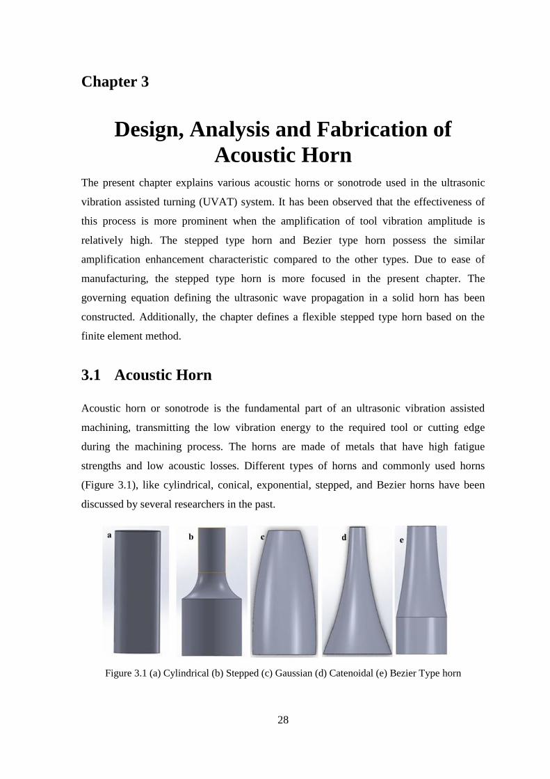
28
Chapter 3
Design, Analysis and Fabrication of
Acoustic Horn The present chapter explains various acoustic horns or sonotrode used in the ultrasonic
vibration assisted turning (UVAT) system. It has been observed that the effectiveness of
this process is more prominent when the amplification of tool vibration amplitude is
relatively high. The stepped type horn and Bezier type horn possess the similar
amplification enhancement characteristic compared to the other types. Due to ease of
manufacturing, the stepped type horn is more focused in the present chapter. The
governing equation defining the ultrasonic wave propagation in a solid horn has been
constructed. Additionally, the chapter defines a flexible stepped type horn based on the
finite element method.
3.1 Acoustic Horn
Acoustic horn or sonotrode is the fundamental part of an ultrasonic vibration assisted
machining, transmitting the low vibration energy to the required tool or cutting edge
during the machining process. The horns are made of metals that have high fatigue
strengths and low acoustic losses. Different types of horns and commonly used horns
(Figure 3.1), like cylindrical, conical, exponential, stepped, and Bezier horns have been
discussed by several researchers in the past.
Figure 3.1 (a) Cylindrical (b) Stepped (c) Gaussian (d) Catenoidal (e) Bezier Type horn

Chapter 3 Design, Analysis and Fabrication of Acoustic Horn
29
Since, the advantages obtained from the ultrasonic vibration assisted manufacturing is
due to the intermittent motion of the cutting insert attached to the horn, generally, the
stepped and Bezier type horn possessing higher amplification compared to the other horns,
are used [36]. Selection of geometric shape of sonotrode depends on technological
operation, amplification factor and ease of manufacturing. Bezier and stepped horns have
almost same amplification factor [36]. However, to fabricate a Bezier horn, one may
require employment of copy turning or NC machine which may not be available [104]. So,
stepped type is chosen over Bezier type. Further, stepped type horn has been extensively
used and investigated due to ease of manufacturing and higher amplification [103, 127].
3.2 Acoustic Wave Equation
The plane wave equation can explain the propagation of the ultrasonic wave in the solid
medium. The favorable ultrasonic vibration required to propagate through the horn is the
longitudinal mode of vibration.
Let‘s consider a non-uniform cylinder with a longitudinal mode as shown in the Figure
3. 2. The direction of vibration is along the axis of the cylinder. A small element of ‗dx‘ is
chosen for the analysis.
Figure 3.2 Non-uniform cylinder with a small element, dx [101]
Let ‗u‘ be the displacement at a distance x from the origin or reference, and it becomes
dx
x
u u at a distance of dx)(x . So the total displacement due to change in the
position can be written as

Chapter 3 Design, Analysis and Fabrication of Acoustic Horn
30
Total displacement, dxx
u udx
x
u u
(2)
The strain of the element is given by
Strain, x
u
dx
dxx
u
(3)
Let, A (x) be the cross-sectional area of the element vary with the position of the element
is the density of the material, E is the modulus of elasticity of the material, F is the force
acting axially on the cylinder, Net force acting on the element is given by,
2
2
2
2
****t
udxxA
t
udmFdx
x
FF
2
2
***t
udxxAdx
x
F
(4)
Where, dm is the mass of the element, 2
2
t
u
is the acceleration of the element.
Further, substituting the value of strain from Eq. (3), the stress generated on the element
due to vibration is given by
Stress, x
uEEx
** (5)
Since, xA area, onalCrosssecti*)σ (Stress,F force, x , therefore, Eq. (4) can be written
as.
2
2
****
t
udxxAdx
x
xAx
2
2
***t
udxxAdx
x
xAdx
xxA x
x
2
2
2
2
*******t
udxxAdx
x
xA
x
uEdx
x
uExA
x
uE
x
xA
x
u
xA
E
t
u2
2
2
2
****
0**11
2
2
2
2
2
x
u
x
xA
x
u
xAt
u
C (6)

Chapter 3 Design, Analysis and Fabrication of Acoustic Horn
31
EC where, 2
The displacement can be represented by,
tNtMtu coscos (7)
Where, is the angular velocity, M and N are constants. So, the acceleration can be
defined as,
ut
u 2
2
2
(8)
The Eq. (6) can be written as,
0***1
2
2
2
2
u
Cx
xA
x
u
xAx
u (9)
The above Eq. (9) represents the one-dimensional plane wave equation.
3.3 Cylindrical Horn
Cylindrical horn or uniform horn is the basic horn used in ultrasonic vibration assisted
manufacturing. The wave equation propagating through this horn can be found out by
making cross sectional area constant shown in the Figure 3.3 and can be written as,
01
2
2
2
2
2
x
u
t
u
C (10)
Figure 3.3 Longitudinal vibration propagation in cylindrical horn with uniform area
The solution equation can be written as,
tTxXtxU *, (11)

Chapter 3 Design, Analysis and Fabrication of Acoustic Horn
32
Or,2
22
2
2
**x
XCT
t
TX
(12)
Let, 2
2
2
2
22
*1
* Pt
T
Tx
X
X
C
or, 0*2
2
2
2
X
C
P
x
X,
(13)
and, 0*2
2
2
TP
t
T
(14)
The general solution for Eq. (13) and (14) are given as,
xC
PBx
C
PAxX
cossin (15)
and, PtBPtAtP cossin 11 (16)
where, A, B, A1 and B1 are the constants and can be found out applying boundary
conditions and fP 2 is angular frequency
The general solution for the Eq. (11) can be written as,
1
11 cossin*cossin,n
PtBPtAxC
PBx
C
PAtxU (17)
When the horn is in the free- free conditions without any external load, the boundary
conditions are,
0
00
lx
x
x
u
x
u
(18)
Applying the boundary conditions on the general solution, we will get,
nl
C
Psin0*sin (19)
or,
E
l
n
l
CnP
, n, order of the mode= 1, 2, 3, 4…
or,
E
l
nfP
2 (20)
So, natural frequency for n=1 is,
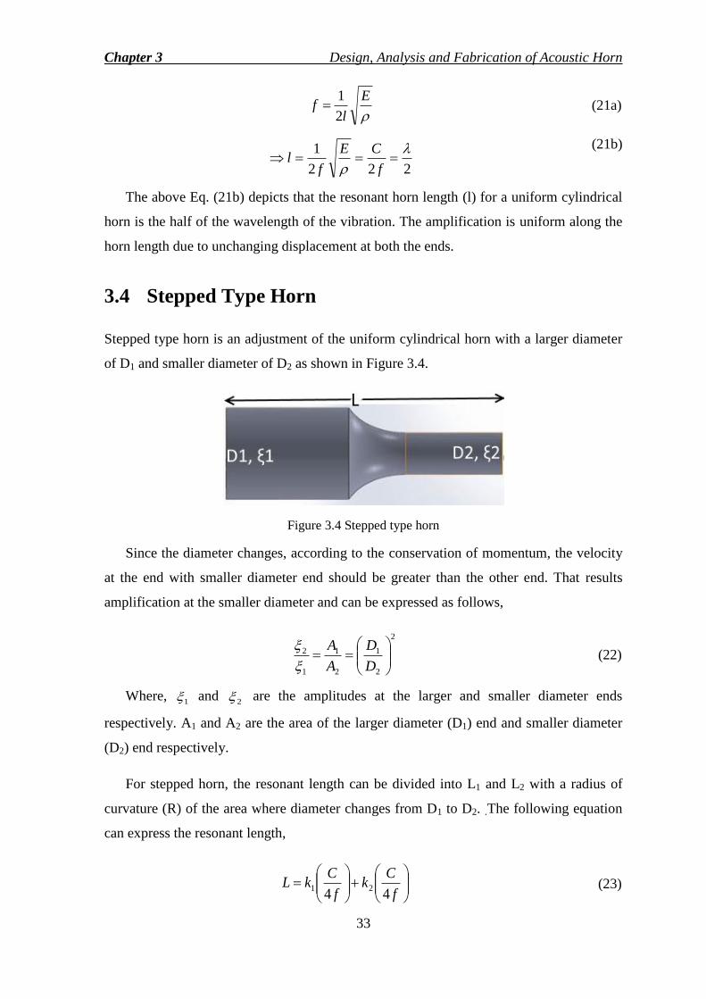
Chapter 3 Design, Analysis and Fabrication of Acoustic Horn
33
E
lf
2
1 (21a)
222
1
f
CE
fl
(21b)
The above Eq. (21b) depicts that the resonant horn length (l) for a uniform cylindrical
horn is the half of the wavelength of the vibration. The amplification is uniform along the
horn length due to unchanging displacement at both the ends.
3.4 Stepped Type Horn
Stepped type horn is an adjustment of the uniform cylindrical horn with a larger diameter
of D1 and smaller diameter of D2 as shown in Figure 3.4.
Figure 3.4 Stepped type horn
Since the diameter changes, according to the conservation of momentum, the velocity
at the end with smaller diameter end should be greater than the other end. That results
amplification at the smaller diameter and can be expressed as follows,
2
2
1
2
1
1
2
D
D
A
A
(22)
Where, 1 and
2 are the amplitudes at the larger and smaller diameter ends
respectively. A1 and A2 are the area of the larger diameter (D1) end and smaller diameter
(D2) end respectively.
For stepped horn, the resonant length can be divided into L1 and L2 with a radius of
curvature (R) of the area where diameter changes from D1 to D2. .The following equation
can express the resonant length,
f
Ck
f
CkL
4421 (23)
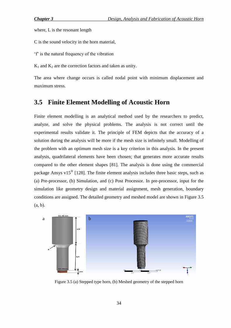
Chapter 3 Design, Analysis and Fabrication of Acoustic Horn
34
where, L is the resonant length
C is the sound velocity in the horn material,
‗f‘ is the natural frequency of the vibration
K1 and K2 are the correction factors and taken as unity.
The area where change occurs is called nodal point with minimum displacement and
maximum stress.
3.5 Finite Element Modelling of Acoustic Horn
Finite element modelling is an analytical method used by the researchers to predict,
analyze, and solve the physical problems. The analysis is not correct until the
experimental results validate it. The principle of FEM depicts that the accuracy of a
solution during the analysis will be more if the mesh size is infinitely small. Modelling of
the problem with an optimum mesh size is a key criterion in this analysis. In the present
analysis, quadrilateral elements have been chosen; that generates more accurate results
compared to the other element shapes [81]. The analysis is done using the commercial
package Ansys v15®
[128]. The finite element analysis includes three basic steps, such as
(a) Pre-processor, (b) Simulation, and (c) Post Processor. In pre-processor, input for the
simulation like geometry design and material assignment, mesh generation, boundary
conditions are assigned. The detailed geometry and meshed model are shown in Figure 3.5
(a, b).
Figure 3.5 (a) Stepped type horn, (b) Meshed geometry of the stepped horn
a b
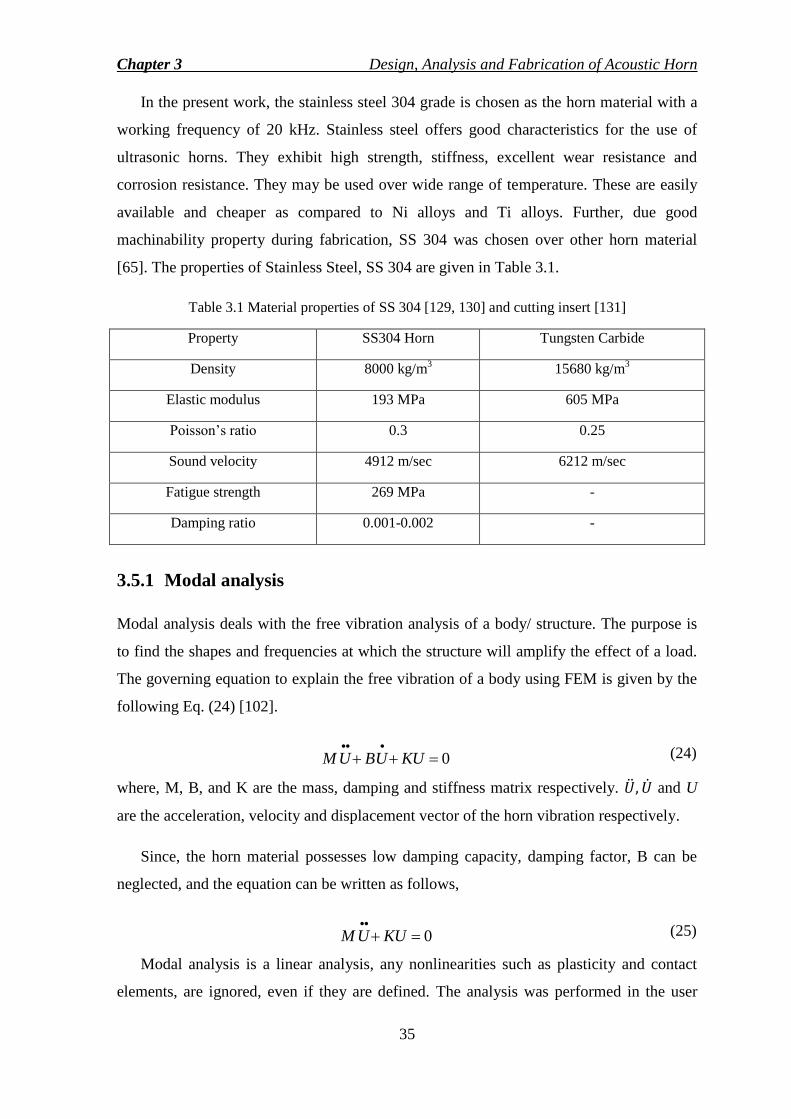
Chapter 3 Design, Analysis and Fabrication of Acoustic Horn
35
In the present work, the stainless steel 304 grade is chosen as the horn material with a
working frequency of 20 kHz. Stainless steel offers good characteristics for the use of
ultrasonic horns. They exhibit high strength, stiffness, excellent wear resistance and
corrosion resistance. They may be used over wide range of temperature. These are easily
available and cheaper as compared to Ni alloys and Ti alloys. Further, due good
machinability property during fabrication, SS 304 was chosen over other horn material
[65]. The properties of Stainless Steel, SS 304 are given in Table 3.1.
Table 3.1 Material properties of SS 304 [129, 130] and cutting insert [131]
Property SS304 Horn Tungsten Carbide
Density 8000 kg/m3 15680 kg/m
3
Elastic modulus 193 MPa 605 MPa
Poisson‘s ratio 0.3 0.25
Sound velocity 4912 m/sec 6212 m/sec
Fatigue strength 269 MPa -
Damping ratio 0.001-0.002 -
3.5.1 Modal analysis
Modal analysis deals with the free vibration analysis of a body/ structure. The purpose is
to find the shapes and frequencies at which the structure will amplify the effect of a load.
The governing equation to explain the free vibration of a body using FEM is given by the
following Eq. (24) [102].
0
KUUBUM (24)
where, M, B, and K are the mass, damping and stiffness matrix respectively. and U
are the acceleration, velocity and displacement vector of the horn vibration respectively.
Since, the horn material possesses low damping capacity, damping factor, B can be
neglected, and the equation can be written as follows,
0
KUUM (25)
Modal analysis is a linear analysis, any nonlinearities such as plasticity and contact
elements, are ignored, even if they are defined. The analysis was performed in the user

Chapter 3 Design, Analysis and Fabrication of Acoustic Horn
36
interface provided in Ansys workbench. The modes were extracted by Block Lanczos
algorithm.
There are numbers of resonant frequencies recorded within the range of 15000 Hz to
30000 Hz. The longitudinal axial mode shape of UVAT is found at 20005 Hz as shown in
Figure 3.6. There are also other modes; twisting mode at 25465 Hz and bending mode at
27253 Hz as shown in Figure 3.7 and 3.8 respectively. It is apparent from Figures 3.7 and
3.8 that these two modes are results of superimposing two or more longitudinal modes in
different directions. This is an undesirable phenomenon which can jeopardize the
advantages of UVAT by hampering the accuracy and surface finish in turning operation.
Hence, the first longitudinal mode is preferred and considered for UVAT.
Figure 3.6 Longitudinal mode (1st mode) of the horn with frequency, 20005 Hz
Figure 3.7 Twisting mode (2nd
mode) of the horn with frequency, 25465 Hz

Chapter 3 Design, Analysis and Fabrication of Acoustic Horn
37
Figure 3.8 Bending mode (3rd
mode) of the horn with frequency, 27253 Hz
3.5.2 Harmonic analysis
Harmonic analysis is used to determine the response of the structure under loading at a
given frequency. It predicts the dynamic behavior of the structure verifying whether the
structure is sustainable to resonance, fatigue effect and other harmful effects. As per the
equipment specification, an output of 10 µm from the transducer is 1.5 times amplified at
the booster end converting to 15 µm. This displacement amplitude is given as a function
of the cyclic load at the input or larger diameter (35mm) of the horn as shown in Figure
3.9a. The experimental setup (Figure 3.9b) to check the horn consists of an ultrasonic
generator, transducer, booster, and the horn.
Figure 3.9 (a) Load applied as a function of displacement, 0.015 mm, (b) Experimental set up for
tuning of horn
a b
Chapter 3 Design, Analysis and Fabrication of Acoustic Horn
38
Based on the analytical calculation, the horn was manufactured and checked for the
tuning using the ultrasonic generator Telsonic®
SG-22 of 2000W and 20 kHz capacity.
Initially, the horn is tuned to 19580 Hz. After a few trials of length shortening, the horn
was tuned to 20 kHz with no load condition. The final effective length of the horn is found
to be 125.5 mm.
3.5.3 Mesh independence test
The variation of natural frequency due to the chosen number of elements during the mesh
generation and solution is the main concern with respect to the accuracy of the result and
computational time. When the number of an element is less, results are showing a
significant error because of inaccurate approximation. The Figure 3.10 shows the mesh
convergence and 20628 numbers of 3D elements (quadrilateral type) are taken to conserve
computation time without hampering the accuracy of the result.
Figure 3.10 Mesh independence test
3.6 Comparison of Analytical and Experimental Results
Based on the modal and harmonic analysis, the horn was manufactured, and the actual
length of the stepped horns was found to be 125.5 mm. The fabricated horn with the
dimensions is shown in Figure 3.11.

Chapter 3 Design, Analysis and Fabrication of Acoustic Horn
39
Figure 3.11 Fabricated stepped horn with dimensions
Resonant length corresponding to the operating frequency, 20 kHz ± 500 Hz obtained
from both analytical and experimental methods are presented in Table 3.2. The
amplification results obtained from theoretically and analytically have been compared and
given in Table 3.3. From the harmonic analysis; it can be concluded that the results quite
satisfy the theoretical calculation. Further, the directional deformation from the FEM is
shown in Figure 3.12 (a, b) indicating a nodal point at a distance of 58 mm from the
bigger end.
Table 3.2 Comparison of resonant lengths of the stepped horn
Results Analytical (mm) Experimental (mm) Error (%)
Resonant length 124 125.5 1.19
Table 3.3 Comparison of amplification ratio
Results Theoretical Analytical from FEM Error (%)
Amplification ratio 3.0625 3.0110 1.68

Chapter 3 Design, Analysis and Fabrication of Acoustic Horn
40
Figure 3.12 (a) Amplitude amplification corresponding to the length of horn (b) Directional
deformation along the axis of the stepped horn
3.7 Horn Parameters on the Natural Frequency
There are mainly two parameters which affect the natural frequency of a stepped type
horn. Those are resonant length and radius of curvature. The effects are shown in Tables
3.4 and 3.5. From the result, we can conclude that the length of the horn has an inverse
effect on the natural frequency. Also, as the radius of curvature increases, the natural
frequency gets increased. So, adjusting these parameters in a model, we can get the
desired natural frequency with the final horn geometry.
In a single or uniform body, due to the vibration, the end of the horn subject to wear
and tear that affects the tuning after repeated use as observed and shown in Figure 3.13.
Therefore, a flexible acoustic stepped type horn has been proposed to prevent from
throwing out the complete horn due to wear and tear avoiding wastages of material, which
will be more cost effective.
Table 3.4 Effect of length (L) on natural frequency
Length, L (mm) Radius of curvature, R (mm) Frequency, f (Hz)
124.5 10 19956
124 10 20005
125 10 19775
126 10 19611
a b
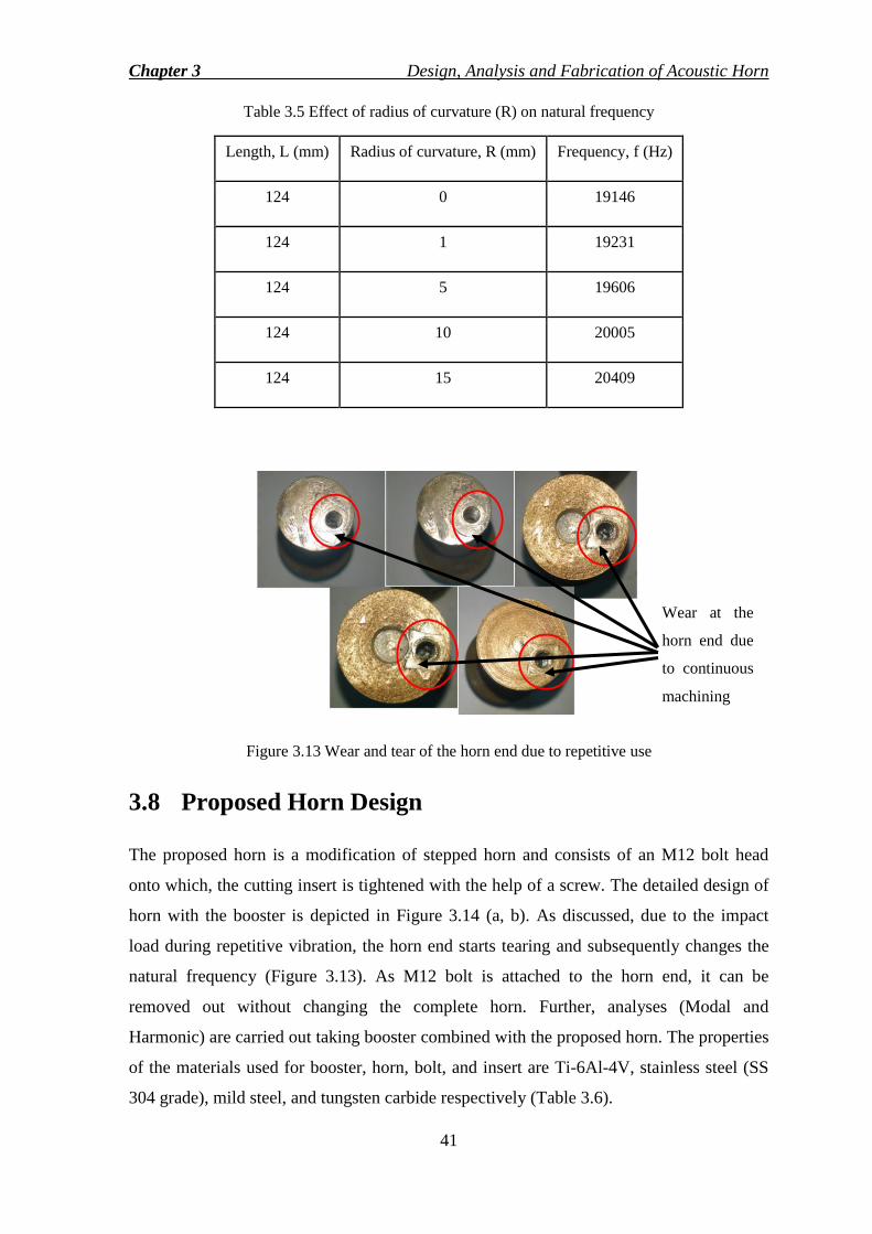
Chapter 3 Design, Analysis and Fabrication of Acoustic Horn
41
Table 3.5 Effect of radius of curvature (R) on natural frequency
Length, L (mm) Radius of curvature, R (mm) Frequency, f (Hz)
124 0 19146
124 1 19231
124 5 19606
124 10 20005
124 15 20409
Figure 3.13 Wear and tear of the horn end due to repetitive use
3.8 Proposed Horn Design
The proposed horn is a modification of stepped horn and consists of an M12 bolt head
onto which, the cutting insert is tightened with the help of a screw. The detailed design of
horn with the booster is depicted in Figure 3.14 (a, b). As discussed, due to the impact
load during repetitive vibration, the horn end starts tearing and subsequently changes the
natural frequency (Figure 3.13). As M12 bolt is attached to the horn end, it can be
removed out without changing the complete horn. Further, analyses (Modal and
Harmonic) are carried out taking booster combined with the proposed horn. The properties
of the materials used for booster, horn, bolt, and insert are Ti-6Al-4V, stainless steel (SS
304 grade), mild steel, and tungsten carbide respectively (Table 3.6).
Wear at the
horn end due
to continuous
machining
Chapter 3 Design, Analysis and Fabrication of Acoustic Horn
42
Figure 3.14 (a) Booster dimensions, (b) Assembly of horn with booster
Table 3.6 Material properties used in the proposed horn and booster [2, 129, 131, 132]
Property Ti-6Al-4V SS304 Horn Mild steel bolt Tungsten Carbide
Density 4430 kg/m3 8000 kg/m
3 7780 kg/m
3 15680 kg/m
3
Elastic modulus 113 GPa 193 GPa 210 GPa 605 GPa
Poisson‘s ratio 0.342 0.3 0.3 0.25
Sound velocity 5050 m/sec 4912 m/sec 5195 m/sec 6212 m/sec
Fatigue strength 510 MPa 269 MPa - -
Yield Stress - 202 MPa - -
3.8.1 Modal analysis results
The assembly of the booster and the proposed horn was undergone modal analysis using
the free vibration approach. The longitudinal mode was found at a frequency of 20008 Hz.
The three different modes obtained during modal analysis are depicted in Figure 3.15. The
analytical length was compared with the fabricated length of the assembly with an error
percentage of 1.63 % given in Table 3.7 (for longitudinal mode).
Chapter 3 Design, Analysis and Fabrication of Acoustic Horn
43
Figure 3.15 (a) Meshed model for booster with horn, (b) Longitudinal mode at 20008 Hz, (c)
Bending mode at 20800Hz and (d) Twisting mode at 23485 Hz
Table 3.7 Comparison of lengths obtained analytically and experimentally
Results Analytical (mm) Experimental (mm) Error (%)
Resonant Length
(Only Horn) 120.73 125 3.40
Resonant length
(Booster + Horn) 256.23 260.5 1.63
3.8.2 Harmonic analysis results
The primary results obtained from the harmonic analysis are amplification ratio and
dynamic characteristics of the model. The dynamic results include stress generation and its
concentration along the length of the model. A comparative analysis is represented in the
following Table 3.8.
Table 3.8 Comparison of amplification ratio
Results Theoretical Analytical Error (%)
Amplification ratio 3.0625 2.991 2.33
a b
c d
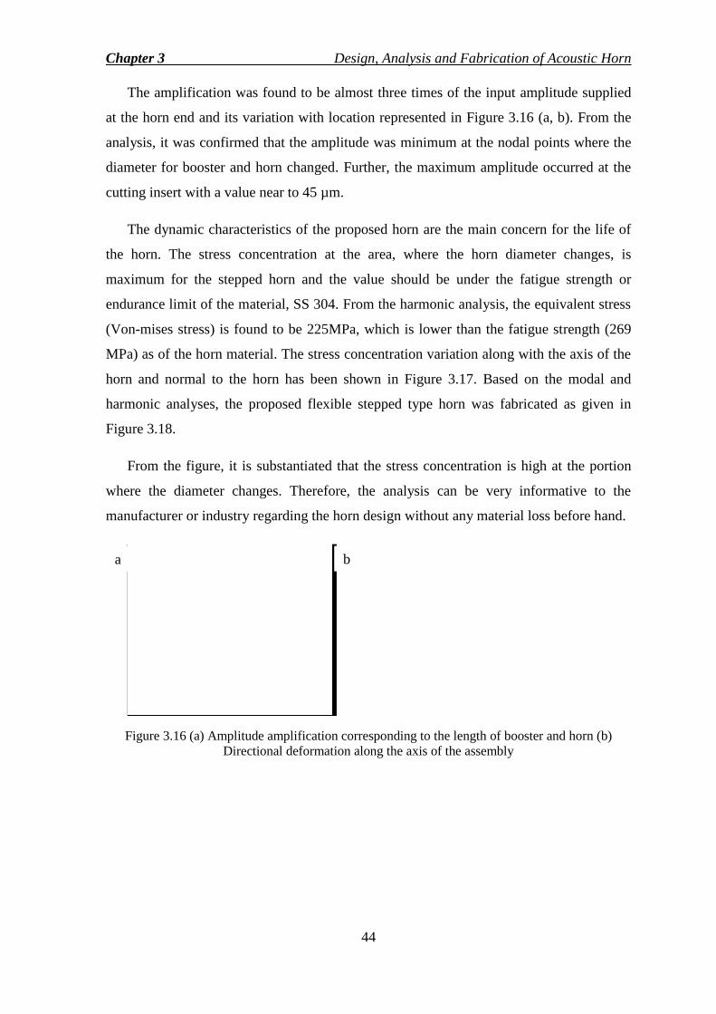
Chapter 3 Design, Analysis and Fabrication of Acoustic Horn
44
The amplification was found to be almost three times of the input amplitude supplied
at the horn end and its variation with location represented in Figure 3.16 (a, b). From the
analysis, it was confirmed that the amplitude was minimum at the nodal points where the
diameter for booster and horn changed. Further, the maximum amplitude occurred at the
cutting insert with a value near to 45 µm.
The dynamic characteristics of the proposed horn are the main concern for the life of
the horn. The stress concentration at the area, where the horn diameter changes, is
maximum for the stepped horn and the value should be under the fatigue strength or
endurance limit of the material, SS 304. From the harmonic analysis, the equivalent stress
(Von-mises stress) is found to be 225MPa, which is lower than the fatigue strength (269
MPa) as of the horn material. The stress concentration variation along with the axis of the
horn and normal to the horn has been shown in Figure 3.17. Based on the modal and
harmonic analyses, the proposed flexible stepped type horn was fabricated as given in
Figure 3.18.
From the figure, it is substantiated that the stress concentration is high at the portion
where the diameter changes. Therefore, the analysis can be very informative to the
manufacturer or industry regarding the horn design without any material loss before hand.
Figure 3.16 (a) Amplitude amplification corresponding to the length of booster and horn (b)
Directional deformation along the axis of the assembly
a b

Chapter 3 Design, Analysis and Fabrication of Acoustic Horn
45
Figure 3.17 Equivalent stress magnitude along the axis of the assembly
Figure 3.18 Fabricated flexible stepped horn with dimension
3.9 Conclusions
The experimental, mathematical, computational modeling of the single body stepped horn,
and a flexible stepped horn were carried out. The following conclusions can be drawn
from the observations:
a. Unlike a conventional design of horn i.e. single body horn design, a flexible type
has been proposed and analyzed using finite element method.
b. The resonant horn length was found out from the numerical method corresponding
to the operating ultrasonic frequency, 20 kHz ± 500 Hz and compared with the
experimental results. The horn lengths for single uniform stepped horn, and

Chapter 3 Design, Analysis and Fabrication of Acoustic Horn
46
flexible horn were found to be 125.5mm and 125mm with error percentages of
1.19 % and 3.40 % respectively.
c. From the free vibration analysis, different modes were found out, and grid
independence test was performed to get an optimum number of elements, i.e.
20628 to conserve computation time without hampering the accuracy of the result.
d. Dynamic analysis results confirm an allowable stress concentration range for
different stresses during the cyclic loading that is below the fatigue strength of the
proposed horn material. Additionally, the maximum stress is observed at the nodal
points.
e. Further, both theoretical and numerically obtained amplification ratios were
compared. The error of 1.68% and 2.33% are found for conventional stepped horn
and flexible horn respectively. It substantiates that finite element method is a
powerful tool to model and analyze the prototype before the actual fabrication,
which is cost saving and economical.

79
Chapter 5
Numerical Modelling and Comparison of
Results The present chapter focuses on building a thermo-mechanical model for CT and UVAT to
investigate the mechanism, effect of controlling parameters and prediction of output
responses. The analysis, a three-dimensional finite element model, assists in understanding
the CT and UVAT processes focusing on the cutting zone, material behavior, and outputs.
Further, model validation was carried out selecting proper friction model, flow stress, and
other thermal conditions.
5.1 Numerical Modelling
A 3D thermo-mechanical coupled finite element model was prepared to understand both
the processes using the commercial FEM software Deform 3D® v10.2. The model is based
on the Lagrangian incremental procedure with continuous remeshing criteria that allows
processing the transient analysis. The present model accommodates the mechanical
processes along with the temperature evolution, damage, stress generation, strain rate etc.,
which are thermally related to each other during the plastic deformation at the cutting
zone. Also, it includes temperature dependent factors like thermal conductivity, density,
specific heat, and material flow stress. Remeshing is an important criterion in the model
that helps to continue the simulation process when there is a generation of distorted mesh
at the cutting zone. The numerical model preparation and investigation can be classified in
three steps [37] such as,
(i) Pre-processor
(ii) Simulation engine
(iii) Post-processor
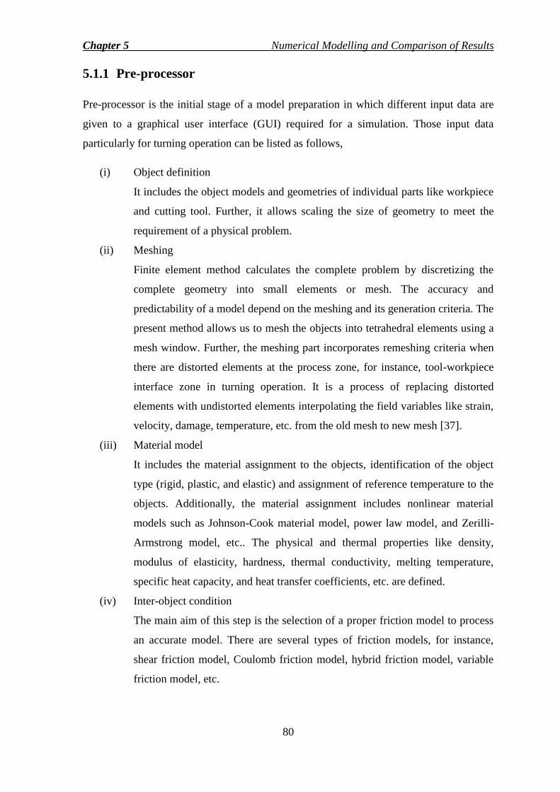
Chapter 5 Numerical Modelling and Comparison of Results
80
5.1.1 Pre-processor
Pre-processor is the initial stage of a model preparation in which different input data are
given to a graphical user interface (GUI) required for a simulation. Those input data
particularly for turning operation can be listed as follows,
(i) Object definition
It includes the object models and geometries of individual parts like workpiece
and cutting tool. Further, it allows scaling the size of geometry to meet the
requirement of a physical problem.
(ii) Meshing
Finite element method calculates the complete problem by discretizing the
complete geometry into small elements or mesh. The accuracy and
predictability of a model depend on the meshing and its generation criteria. The
present method allows us to mesh the objects into tetrahedral elements using a
mesh window. Further, the meshing part incorporates remeshing criteria when
there are distorted elements at the process zone, for instance, tool-workpiece
interface zone in turning operation. It is a process of replacing distorted
elements with undistorted elements interpolating the field variables like strain,
velocity, damage, temperature, etc. from the old mesh to new mesh [37].
(iii) Material model
It includes the material assignment to the objects, identification of the object
type (rigid, plastic, and elastic) and assignment of reference temperature to the
objects. Additionally, the material assignment includes nonlinear material
models such as Johnson-Cook material model, power law model, and Zerilli-
Armstrong model, etc.. The physical and thermal properties like density,
modulus of elasticity, hardness, thermal conductivity, melting temperature,
specific heat capacity, and heat transfer coefficients, etc. are defined.
(iv) Inter-object condition
The main aim of this step is the selection of a proper friction model to process
an accurate model. There are several types of friction models, for instance,
shear friction model, Coulomb friction model, hybrid friction model, variable
friction model, etc.

Chapter 5 Numerical Modelling and Comparison of Results
81
(v) Simulation controls
It defines the various types of solution and algorithms that can be assigned to
the model assembling the input data. Further, the simulation time, steps, data
collection, and saving can be controlled with simulation controls.
(vi) Boundary conditions
It includes all the kinetic and thermal boundary conditions associated with the
physical problem. Particularly in tuning models, while assigning the cutting
velocity, the workpiece surfaces are fixed expect the top surface reducing the
degree of freedom. Thermal boundary conditions include assignment of heat
sources, assignment of temperature and heat transfer constants to particular
surfaces.
5.1.2 Simulation engine
The simulation of the model is carried out by the solution method assigned in the
simulation control. Different solution methods are direct iteration, Newton-Raphson
method etc. Further, the simulation results vary with the type of algorithm used in a
model. Different algorithms can be used are Lagrangian algorithm, Arbitrary Lagrangian
Eulerian algorithm, steady state algorithm etc. The simulation process can be observed in
a simulation graphics window to study the output responses.
5.1.3 Post-processor
The simulation results are stored in the post-processor step in a database file (*.DB).The
output responses like cutting force, temperature evolution, stress and strain generation,
tool wear, and microstructure can be studied.
5.2 Model Preparation for CT and UVAT
The workpiece with a dimension of 5 mm in length x 1.5 mm in breadth x 0.5 mm in
height was used as a plastic or deformable body. It was discretized into 20533 numbers of
tetrahedral elements later increased to 23831 numbers due to remeshing with refined mesh
at the cutting zone with an element size of 30 µm. The element size or number of elements
is optimally chosen after performing a grid independency test (when it was found that
there was no significant change in the results due to mesh numbers). The cutting tool was
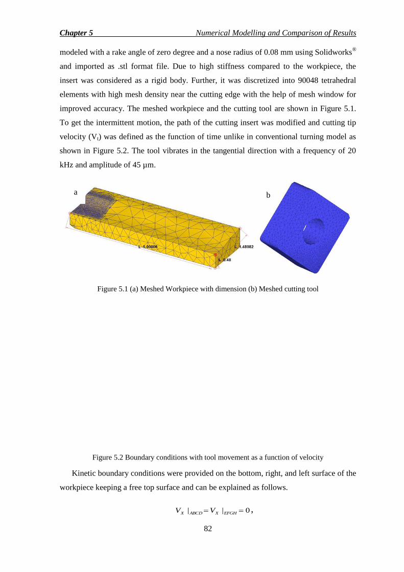
Chapter 5 Numerical Modelling and Comparison of Results
82
modeled with a rake angle of zero degree and a nose radius of 0.08 mm using Solidworks®
and imported as .stl format file. Due to high stiffness compared to the workpiece, the
insert was considered as a rigid body. Further, it was discretized into 90048 tetrahedral
elements with high mesh density near the cutting edge with the help of mesh window for
improved accuracy. The meshed workpiece and the cutting tool are shown in Figure 5.1.
To get the intermittent motion, the path of the cutting insert was modified and cutting tip
velocity (Vt) was defined as the function of time unlike in conventional turning model as
shown in Figure 5.2. The tool vibrates in the tangential direction with a frequency of 20
kHz and amplitude of 45 µm.
Figure 5.1 (a) Meshed Workpiece with dimension (b) Meshed cutting tool
Figure 5.2 Boundary conditions with tool movement as a function of velocity
Kinetic boundary conditions were provided on the bottom, right, and left surface of the
workpiece keeping a free top surface and can be explained as follows.
0|| EFGHXABCDX VV ,
a b

Chapter 5 Numerical Modelling and Comparison of Results
83
0| AFGDZV ,
sec/300||| mmVVVV AFDGYEFGHYABCDY
The workpiece moves with a cutting velocity of Vc = 300 mm/sec that is below the
critical velocity, or the maximum tool tip velocity (Vt) to process an effective ultrasonic
vibration effect during the turning operation. The initial temperature was set as 200C and
the top free surface was assigned with a convection coefficient constant (hc) of 0.02
N/mm/sec/C [37]. Initial simulations of both the cutting processes were carried out with
minimum cutting speed of 300 mm/sec, feed of 0.04 mm/rev and depth of cut of 0.14 mm.
A non-linear strain rate and temperature sensitive material model to describe the
material behavior of Ti-6Al-4V was implemented using Johnson and Cook model [37] as
shown in Eq. (33). The corresponding parameters in Eq. (33) show the dependencies of
flow stress on strain, strain rate, and thermal softening respectively.
mn ETDCBA *
00
ln1
(33)
where, rm
r
TT
TTT
&, are yield stress, plastic strain, and strain rate respectively. Tr and Tm are the
room temperature and melting temperature of TI-6Al-4V respectively. The material
coefficients are mentioned in the following Table 5.1.
Table 5.1 Material coefficients used in simulation [120]
Variable 0
A B C n m α D E
Unit 1/s MPa MPa
Value 2000 724.1 683.1 0.035 0.47 1 0 1 1
In the above equation, constants A, B, C, n, m are called as the yield stress coefficient,
plastic strain coefficient, strain rate coefficient, hardening coefficient and thermal
softening coefficient respectively. The friction model implemented in this model is simple
shear friction model, which states that the friction force depends on the fraction of
Chapter 5 Numerical Modelling and Comparison of Results
84
equivalent shear stress, not on the normal force like the Coulomb friction model [37]. The
friction in the interface zone is modeled using the Eq. (34) given below.
km (34)
where, τ is friction force, k is equivalent shear stress and m is the shear friction factor.
The selection of this friction model with friction factor, m=0.82 is based on several
researches [124, 125, 137, 138] where this model has been validated comparing with the
cutting forces, temperatures, and chip geometries. The thermal boundary conditions were
applied for the heat losses from the tool or workpiece surfaces to the environment, and
from the workpiece or chip surfaces to the cutting tool. The first process is affected by a
convective coefficient (hc) and the latter is affected by heat transfer coefficient or interface
heat transfer coefficient (h). These can be explained mathematically as follows.
)( 0TThq wc (35)
)( tw TThq (36)
where hc and h are convection coefficient and heat transfer coefficient respectively, Tw
is workpiece or chip surface temperature, T0 is the ambient temperature and Tt is the tool
surface temperature during the cutting process. The complete method for the above
modelling is presented as a flow chart (Appendix C).
5.3 Simulation Results and Discussions
To validate the numerical model, the model and experimental results for cutting forces and
tool tip temperature were compared for both the cutting processes and discussed as
follows.
5.3.1 Cutting force validation
A model can never be accepted until the results are validated with the experimental
results. Validations for several runs were made comparing the numerical results with the
measured results for the cutting forces during CT and UVAT as shown in Figures 5.3 (a)
and (b). Good accuracy can be observed as the relative error percentages (R.E.) are low for
Chapter 5 Numerical Modelling and Comparison of Results
85
most of the runs with a highest value of 30.03% for the run number 91 during CT
simulation. The relative error for both the models can be found out by following Eq. (37).
The average error for CT and UVAT were calculated and found to be 9.50% and 6.80%
respectively. The lower percentages of average errors depict that the models can be
accepted to investigate the effect of process parameters predicting complex outputs
occurring at the cutting zone.
100 valuealExperiment
valueSimulation-Value alExperiment(%)Error Relative (37)
Additionally, Figure 5.4 shows the comparative force history diagram for both the
cutting processes for a single cycle after reaching steady state. On applying the ultrasonic
vibration, the magnitude of average force was significantly reduced, almost 40% due to
the intermittent motion of the cutting tool in the case of UVAT. The generated force was
continuous and reached a steady state in case of CT process, due to continuous
engagement of the insert with the workpiece. Inversely, in UVAT process, force reached
to the maximum only when the insert was fully in contact with the workpiece and chip.
Further, the transient and persistent phenomenon of force generation can be explained
from the stress generations in different stages of the cycle (as in Figures 5.5 and 5.6), such
as, during the first stage, the insert approaches towards the workpiece with an effective
stress of 0.079 MPa. As the insert in contact with the workpiece during the penetration
stage of the cycle, the stress increases up to 1820 MPa and reaches a maximum value of
2890 MPa nearly equal to the CT process. In the 3rd
stage, unloading stage, the stress
generation decreases from 2890 MPa, and ceases to 0.087 MPa during the withdrawal
stage of the cycle. On the contrary, the stress generation was found to be a continuous
process approx. 2800 MPa during CT process.

Chapter 5 Numerical Modelling and Comparison of Results
86
Figure 5.3 Comparison of main cutting forces with the measured results (a) CT (b) UVAT
Figure 5.7 (a)-(d) depict the effect of cutting velocity on the forces for both the cutting
processes. Cutting velocity has a direct effect on the insert movement; as the increasing
cutting velocity increases the tool engagement time resulting higher cutting forces and the
effect of UVAT process ceases as the velocity reaches to the critical velocity of the cutting
tip (with increase of TWCR).
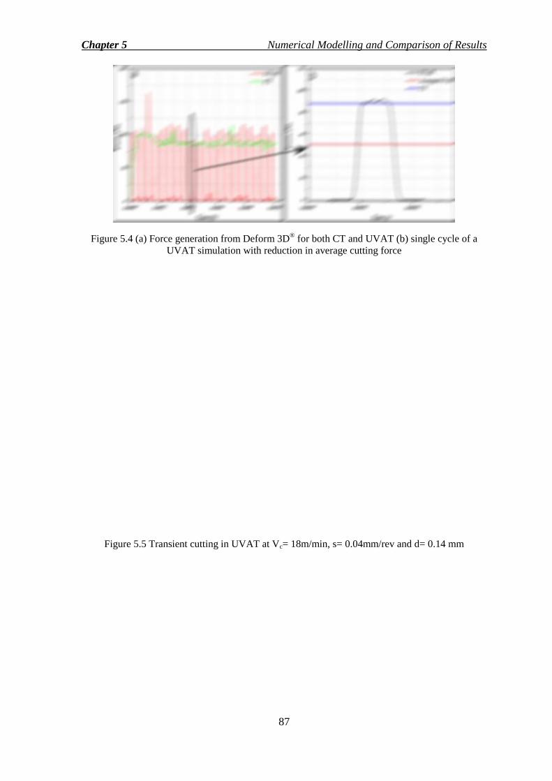
Chapter 5 Numerical Modelling and Comparison of Results
87
Figure 5.4 (a) Force generation from Deform 3D® for both CT and UVAT (b) single cycle of a
UVAT simulation with reduction in average cutting force
Figure 5.5 Transient cutting in UVAT at Vc= 18m/min, s= 0.04mm/rev and d= 0.14 mm
Chapter 5 Numerical Modelling and Comparison of Results
88
Figure 5.6 Continuous cutting in CT at Vc= 18m/min, s= 0.04mm/rev and d= 0.14 mm
Figure 5.7 Effect of cutting velocity on the main cutting force obtained from both experiment and
simulation for CT and UVAT at (a) s= 0.04 mm/rev, d= 0.14 mm (b) s= 0.08 mm/rev, d= 0.18 mm
(c) s= 0.08 mm/rev, d= 0.26 mm (d) s= 0.08 mm/rev, d= 0.26 mm
Chapter 5 Numerical Modelling and Comparison of Results
89
5.3.2 Tool temperature validation
For several experimental runs, simulations were carried out to analyze the thermal
phenomena occurred in the cutting zone and tool temperature evolution as well. To
achieve the steady state temperature, a global heat transfer coefficient (h= 1000 kW/m2 0
C
[124, 137]) was carefully chosen. Figure 5.8 depicts the tool tip temperature evolution for
different heat transfer coefficient, h with a temperature convergence for h=1000 kW/m2
0C.
Figure 5.8 Tool tip temperature evolution with different values of h (in kW/m2 0
C)
The steady state tool temperatures obtained from both experimental and simulations
were compared with a maximum error percentage of 30.95% for the 28th run. Figures 5.9
(a) and (b) depict a comparative case for the tool temperature evolution for both the
processes. It shows that the simulation results provide quite satisfactory and supported
results for the measured temperature evolution during both the cutting processes making a
good correlation with the experiment. Further, the average relative error for both the CT
model and UVAT results were found to be 8.08% and 9.19% respectively.

Chapter 5 Numerical Modelling and Comparison of Results
90
Figure 5.9 Comparison of simulation results for cutting tool temperature with the measured results
(a) CT (b) UVAT
Steady state temperature was obtained approximately after 0.0003 seconds for several
simulations with h=1000 kW/m2
0C. Figure 5.10 shows the measured and simulated
results for tool tip during both the machining processes. The temperature evolution
characteristics during the UVAT process is oscillating type as due to the intermittent
motion of the cutting insert. During the contact stage, the temperature increases to the
maximum value and cools down during the withdrawal stage, unlike the CT process in
which, the temperature remains steady along with the cutting process due to continuous
engagement of the tool with the workpiece.

Chapter 5 Numerical Modelling and Comparison of Results
91
Figure 5.10 Steady state tool during (18 m/min, f=0.04 mm/rev, d=0.14 mm) (a) Measured
temperature (b) Point tracking result from the FE simulation
Comparing the UVAT simulations results with that of CT, the tool temperature got
reductions like 10.77 %, 12.77 %, and 12.04 % for the run no 53, 12, and 103 respectively
with the cutting velocity of 18m/min, 30 m/min and 40m/min. The possible reasons could
be the aerodynamic lubrication that reduces the heat propagation to the tool during the
separation period due to the intermittent motion of the tool. Also, at the same velocity
having the maximum feed and depth of cut value, the UVAT temperature exceeds the CT
temperature. It implies that not only the lower cutting velocities but also lower feed rates
and depth of cuts are suitable for the UVAT process as far as temperature evolution is
concerned. Further, the tool temperature during UVAT processes inclined towards the CT
temperatures as the speed increases to 30 m/min and surpassed by several percentages as
the velocity reached to 40m/min as shown in Figure 5.11. This can be explained with the
help of UVAT process mechanism; as the cutting velocity increases, the separation time
between the tool and workpiece reduces since the cutting velocity approaches towards the
critical velocity and the effect of additional energy supplied by the ultrasonic vibration
explained by several researchers. Furthermore, the finite element models can predict the
interface temperature that could not be measured during our experiment. The temperature
distribution obtained from the FE model are depicted in Figures 5.12 (a)-(f) with the
temperature characteristics.
a b

Chapter 5 Numerical Modelling and Comparison of Results
92
Figure 5.11 Tool Temperature as a function of cutting velocity for both processes (with constant
s=0.08mm/rev, d=0.18mm)
Figure 5.12 Interface temperature with the average value and temperature distributions for (a, d)
18 m/min (b, e) 30 m/min and (c, f) 40 m/min
Primarily, the temperature distribution on the tool tip surface during the cutting
process affects the tool life and the predicted temperature distribution for both the
processes are shown in Figure 5.13. It explains the tool temperature distribution during
UVAT process drastically reduces due to the vibratory motion of the cutting tool which
could directly affect the tool life in a better way making this process better compared to
the CT process.

Chapter 5 Numerical Modelling and Comparison of Results
93
Figure 5.13 Temperature distributions on the tool surface from the cutting tip (after reaching
steady state)
5.4 Conclusions
In the present chapter, a 3D thermo-mechanical model was prepared for both the cutting
processes considering non-linear material flow stress and a suitable friction model with a
proper global heat transfer coefficient. The following conclusions can be drawn from the
above observations:
(i) The cutting force increased with cutting velocity due to the escalation of
contact period of the tool with the workpiece at a higher velocity. For principal
cutting force, the average relative errors were found to be 9.50% and 6.80% for
CT and UVAT respectively.
(ii) The steady state temperature during the cutting processes has been investigated
by selecting a suitable friction model with global heat transfer coefficient,
h=1000kW/m2 0
C. Tool temperature results have been validated with the
experimental results with the average relative error percentages of 8.08% and
9.19% for CT and UVAT respectively. Further, it has been noted that the
temperature distribution on the tool surface is comparatively lower than tool
temperature distribution during CT process.
(iii) UVAT process does not necessarily reduce the tool temperature always; rather
the evolution of cutting temperature majorly depends on the cutting velocity,
feed rate, and depth of cut. For instance, at a minimum cutting velocity with
minimum feed and depth of cut, the tool temperature during UVAT was found
to be lower than that of CT temperature. But, it surpassed the temperature for

Chapter 5 Numerical Modelling and Comparison of Results
94
CT, when UVAT was carried out with high feed rate and depth of cut.
Therefore, low cutting velocity, feed, and depth of cut were favorable to
UVAT process.
(iv) Finally, the interface cutting temperature was predicted from the model after
the validation of the model and the same found to be increasing with the
increase in cutting velocity.
95
Chapter 6
Chip Morphology, Tool Wear, and
Surface Integrity Investigations Titanium alloy, Ti-6Al-4V shows serious machining challenges due to inherent
characteristics like high hardness at elevated temperature, high affinity towards the cutting
tools and reduced thermal conductivity that demands novel machining processes to cut
these ―hard to cut‖ alloys. Ultrasonic vibration assisted turning is one of the novel
machining process to enhance the machinability of ―hard to cut‖ alloys. In a machining
process, surface finish, tool life, and chip morphology are the basic characteristics that rate
the machinability of material for a particular material removal process. The present
chapter focuses on the investigation of machinability indices like chip morphology,
surface integrity, and tool wear with a comparative study applied to Ti-6Al-4V using CT
and UVAT processes.
6.1 Chip Morphology
The quality of machining and the degree of ease in cutting can be studied from the nature
of chip produced during a cutting process [139]. Further, the nature of chip affects the tool
workpiece interaction influencing the tool life. Chip morphology includes chip reduction
ratio, chip thickness, equivalent chip thickness, and segmentation frequency of the chips.
It is observed that during both the cutting operations, the chips formed were serrated or
saw tooth type. Different terms related to chip morphology are peak height (hmax), valley
height (hmin), pitch of the tooth (Pc), saw tool angle (Φs) shown in Figure 6.1.
It was observed that thicknesses of the chip produced during UVAT were thinner than
that of CT process. Further, the UVAT chips were smooth, more curled, and uniform,
unlike CT chips. The chip thickness during CT was thicker due to the continuous contact
of the tool tip with the workpiece, whereas, the chip formed during UVAT was thinned
due to intermittent contact of the tool with the workpiece. Figure 6.2 shows a comparative
study of chip thickness at different cutting velocities keeping feed, s at 0.08 mm/rev and
depth of cut, d at 0.26 mm. It is evident that chip thickness decreases with the increase of
cutting velocity. The reduction in chip thickness correlates with the cutting force reduction

Chapter 6 Chip Morphology, Tool Wear and Surface Integrity Investigations
96
with the increase in velocity. Similar results were observed by researchers, Li and shih
[114]. It is also observed that the difference between the chip thickness obtained by CT
and UVAT decreases with increase of cutting velocity. It is due to the fact that as cutting
velocity increases, the velocity difference (Between the cutting velocity and tool tip
velocity) decreases, and the UVAT approaches the CT process. Similarly, the chip
reduction coefficient was calculated dividing the chip thickness with the uncut chip
thickness and shown in Figure 6.3.
Figure 6.1 Saw tooth type chip with different terms related to chip
Figure 6.2 Comparison of chip thickness at different cutting velocity for CT and UVAT at constant
feed, s= 0.08 mm/rev, and depth of cut, d= 0.26mm
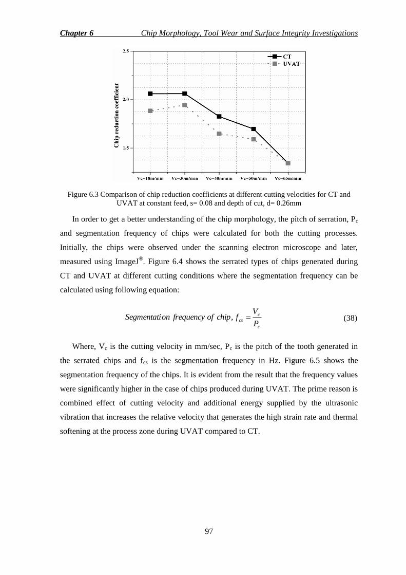
Chapter 6 Chip Morphology, Tool Wear and Surface Integrity Investigations
97
Figure 6.3 Comparison of chip reduction coefficients at different cutting velocities for CT and
UVAT at constant feed, s= 0.08 and depth of cut, d= 0.26mm
In order to get a better understanding of the chip morphology, the pitch of serration, Pc
and segmentation frequency of chips were calculated for both the cutting processes.
Initially, the chips were observed under the scanning electron microscope and later,
measured using ImageJ®. Figure 6.4 shows the serrated types of chips generated during
CT and UVAT at different cutting conditions where the segmentation frequency can be
calculated using following equation:
c
c
csP
VfchipoffrequencyonSegmentati , (38)
Where, Vc is the cutting velocity in mm/sec, Pc is the pitch of the tooth generated in
the serrated chips and fcs is the segmentation frequency in Hz. Figure 6.5 shows the
segmentation frequency of the chips. It is evident from the result that the frequency values
were significantly higher in the case of chips produced during UVAT. The prime reason is
combined effect of cutting velocity and additional energy supplied by the ultrasonic
vibration that increases the relative velocity that generates the high strain rate and thermal
softening at the process zone during UVAT compared to CT.
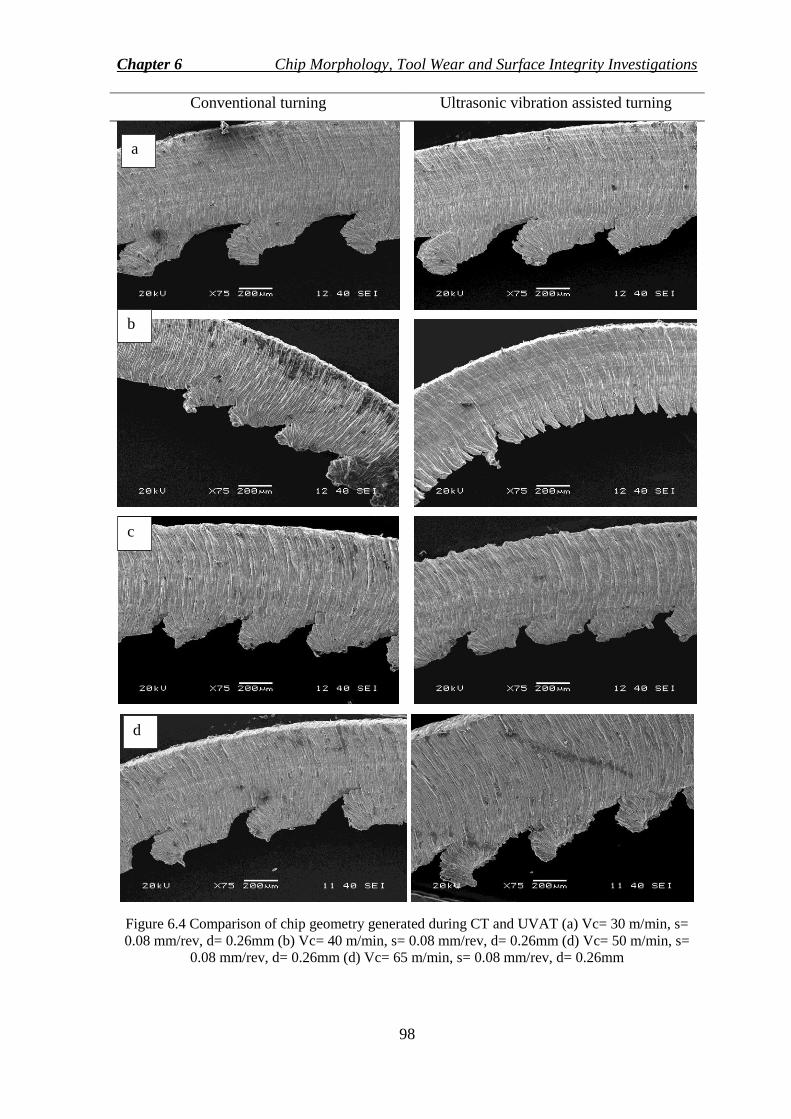
Chapter 6 Chip Morphology, Tool Wear and Surface Integrity Investigations
98
Conventional turning Ultrasonic vibration assisted turning
Figure 6.4 Comparison of chip geometry generated during CT and UVAT (a) Vc= 30 m/min, s=
0.08 mm/rev, d= 0.26mm (b) Vc= 40 m/min, s= 0.08 mm/rev, d= 0.26mm (d) Vc= 50 m/min, s=
0.08 mm/rev, d= 0.26mm (d) Vc= 65 m/min, s= 0.08 mm/rev, d= 0.26mm
a
b
c
d
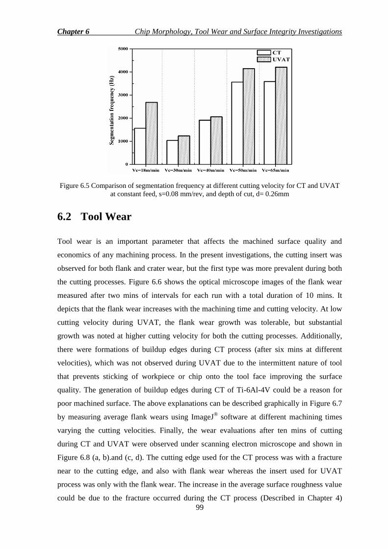
Chapter 6 Chip Morphology, Tool Wear and Surface Integrity Investigations
99
Figure 6.5 Comparison of segmentation frequency at different cutting velocity for CT and UVAT
at constant feed, s=0.08 mm/rev, and depth of cut, d= 0.26mm
6.2 Tool Wear
Tool wear is an important parameter that affects the machined surface quality and
economics of any machining process. In the present investigations, the cutting insert was
observed for both flank and crater wear, but the first type was more prevalent during both
the cutting processes. Figure 6.6 shows the optical microscope images of the flank wear
measured after two mins of intervals for each run with a total duration of 10 mins. It
depicts that the flank wear increases with the machining time and cutting velocity. At low
cutting velocity during UVAT, the flank wear growth was tolerable, but substantial
growth was noted at higher cutting velocity for both the cutting processes. Additionally,
there were formations of buildup edges during CT process (after six mins at different
velocities), which was not observed during UVAT due to the intermittent nature of tool
that prevents sticking of workpiece or chip onto the tool face improving the surface
quality. The generation of buildup edges during CT of Ti-6Al-4V could be a reason for
poor machined surface. The above explanations can be described graphically in Figure 6.7
by measuring average flank wears using ImageJ® software at different machining times
varying the cutting velocities. Finally, the wear evaluations after ten mins of cutting
during CT and UVAT were observed under scanning electron microscope and shown in
Figure 6.8 (a, b).and (c, d). The cutting edge used for the CT process was with a fracture
near to the cutting edge, and also with flank wear whereas the insert used for UVAT
process was only with the flank wear. The increase in the average surface roughness value
could be due to the fracture occurred during the CT process (Described in Chapter 4)

Chapter 6 Chip Morphology, Tool Wear and Surface Integrity Investigations
100
which was not in the case of UVAT process. Further, the failure in the cutting edge causes
the increase in magnitude of force for CT process which is not prominent in the UVAT.
Similar observations were made by several researchers concluding the aerodynamics
lubrication as the major reason for better tool life during UVAT process at lower speed
[34, 70, 82].
Machining
Time CT UVAT CT UVAT
Vc=18 m/min Vc=50 m/min
2 mins
4 mins
6 mins
8 mins
10 mins
Figure 6.6 Flank wear evolution during CT and UVAT at different velocities varying machining
period at constant feed, s= 0.04 mm/rev and depth of cut, d= 0.14mm

Chapter 6 Chip Morphology, Tool Wear and Surface Integrity Investigations
101
Figure 6.7 Average flank wear evolution during CT and UVAT at different velocities varying
machining period at constant feed, s= 0.04 mm/rev and depth of cut, d= 0.14mm
Figure 6.8 SEM image of tool wear at Vc= 18 m/min, s= 0.04 mm/rev, d= 0.14mm for (a,b) CT
process and (c,d) UVAT process.
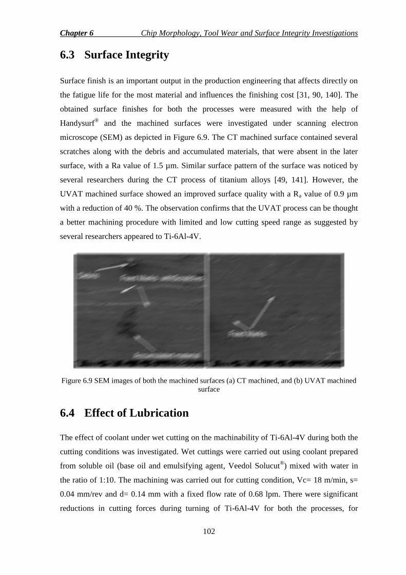
Chapter 6 Chip Morphology, Tool Wear and Surface Integrity Investigations
102
6.3 Surface Integrity
Surface finish is an important output in the production engineering that affects directly on
the fatigue life for the most material and influences the finishing cost [31, 90, 140]. The
obtained surface finishes for both the processes were measured with the help of
Handysurf® and the machined surfaces were investigated under scanning electron
microscope (SEM) as depicted in Figure 6.9. The CT machined surface contained several
scratches along with the debris and accumulated materials, that were absent in the later
surface, with a Ra value of 1.5 µm. Similar surface pattern of the surface was noticed by
several researchers during the CT process of titanium alloys [49, 141]. However, the
UVAT machined surface showed an improved surface quality with a Ra value of 0.9 µm
with a reduction of 40 %. The observation confirms that the UVAT process can be thought
a better machining procedure with limited and low cutting speed range as suggested by
several researchers appeared to Ti-6Al-4V.
Figure 6.9 SEM images of both the machined surfaces (a) CT machined, and (b) UVAT machined
surface
6.4 Effect of Lubrication
The effect of coolant under wet cutting on the machinability of Ti-6Al-4V during both the
cutting conditions was investigated. Wet cuttings were carried out using coolant prepared
from soluble oil (base oil and emulsifying agent, Veedol Solucut®) mixed with water in
the ratio of 1:10. The machining was carried out for cutting condition, Vc= 18 m/min, s=
0.04 mm/rev and d= 0.14 mm with a fixed flow rate of 0.68 lpm. There were significant
reductions in cutting forces during turning of Ti-6Al-4V for both the processes, for
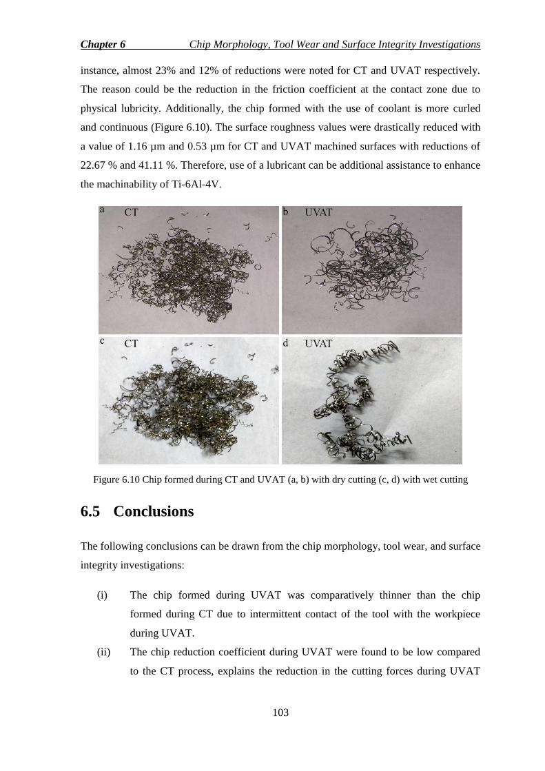
Chapter 6 Chip Morphology, Tool Wear and Surface Integrity Investigations
103
instance, almost 23% and 12% of reductions were noted for CT and UVAT respectively.
The reason could be the reduction in the friction coefficient at the contact zone due to
physical lubricity. Additionally, the chip formed with the use of coolant is more curled
and continuous (Figure 6.10). The surface roughness values were drastically reduced with
a value of 1.16 µm and 0.53 µm for CT and UVAT machined surfaces with reductions of
22.67 % and 41.11 %. Therefore, use of a lubricant can be additional assistance to enhance
the machinability of Ti-6Al-4V.
Figure 6.10 Chip formed during CT and UVAT (a, b) with dry cutting (c, d) with wet cutting
6.5 Conclusions
The following conclusions can be drawn from the chip morphology, tool wear, and surface
integrity investigations:
(i) The chip formed during UVAT was comparatively thinner than the chip
formed during CT due to intermittent contact of the tool with the workpiece
during UVAT.
(ii) The chip reduction coefficient during UVAT were found to be low compared
to the CT process, explains the reduction in the cutting forces during UVAT
Chapter 6 Chip Morphology, Tool Wear and Surface Integrity Investigations
104
than the latter case. Further, the chip reduction coefficient decreased due to
increase in cutting velocity.
(iii) UVAT generated chips had higher segmentation frequency than the CT,
depicts that during UVAT high strain rate and thermal softening occur at the
cutting zone enhancing the material removal rate.
(iv) UVAT enhanced the machinability of Ti-6Al-4V reducing the tool wear to a
great extent. During CT, fracture with flank wear was observed due to
continuous contact of the tool with the workpiece.
(v) UVAT produced an improved machined surface, unlike CT machined surface
with 40% reduction in average surface roughness. Further, the CT machined
surface was having surface errors like debris, scratches and accumulated
material with feed marks. In UVAT machined surface, feed marks were not
prominent with enhanced the surface finish.
(vi) The use of lubrication was effective for both the processes reducing cutting
forces by 23% and 12% for CT and UVAT respectively. Additionally, the
lubricity helped generate an improved machined surface reducing the
roughness magnitude by 22.67 % and 41.11 % for CT and UVAT respectively.

105
Chapter 7
Conclusions The present research focuses on the investigation of turning machinability of titanium
alloy, Ti-6Al-4V during conventional turning and ultrasonic vibration assisted turning.
Further, the turning operations were simulated using finite element model using
Deform3D® to investigate the effect of controlling parameters on the output responses like
cutting force, surface roughness, and tool temperature. Finally, machinability indices like
chip morphology, surface integrity, and tool wear were investigated. The following
observations can be drawn from the above research work.
7.1 Major Findings
The present chapter includes all the major findings obtained from the above chapters
investigating the acoustic horn, experimental and numerical studies of CT and UVAT of
Ti-6Al-4V. The findings can be summarized as follows:
Unlike a conventional design of horn i.e. uniform horn design, a flexible type has
been proposed and analyzed using finite element method. The resonant horn length
was found out from the analytical method corresponding to the operating
ultrasonic frequency, 20 kHz ± 500 Hz and compared with the experimental
results. The horn length for single uniform stepped horn, and flexible horn were
found to be 125.5mm and 125mm with error percentages of 1.19 % and 3.40 %
respectively on comparing with the analytical length.
Dynamic analysis results confirm an allowable stress concentration range for
different stresses during the cyclic loading that is below the fatigue strength (269
MPa) of the proposed horn material. Additionally, the maximum stress is observed
at the nodal points.
Further, both theoretical and analytical amplification ratios were compared. The
errors of 1.68% and 2.33% are found for conventional stepped horn and flexible
horn respectively. It substantiates that finite element method is a powerful tool to

Chapter 7 Conclusions
106
model and analyse the prototype before the actual fabrication, which is cost saving
and economical.
Experimental investigation of both CT and UVAT processes depicted that on
applying ultrasonic vibration to the cutting tool, there were significant reductions
(40.07%, 34.77%, 23.57%, 14.09%, and 5.06% at Vc= 18min to 65 m/min) in
principal cutting forces comparing with the results obtained during the CT.
The UVAT was found to be a novel technique improving the machined surface
while comparing with the results obtained from the CT process. Almost, 41% of
the reduction in average surface roughness was observed during UVAT process
compared to the CT process with a constant velocity of 18m/min varying the depth
of cuts from 0.14 mm to 0.30 mm for different feed rates.
For CT and UVAT operations, the R- Squared and adj. R- Squared values were
found to be above 90% showing the reliability and precision during the
experimental investigations. Similar observations were found for average surface
roughness and tool temperature.
A 3D thermo-mechanical model was prepared for both the cutting processes and
the model was validated comparing the main cutting force results with the
experimental results. For principal cutting force, the average relative errors were
found to be 9.50% and 6.80% for CT and UVAT respectively.
The steady state temperature during the cutting processes has been investigated by
selecting a suitable friction model with global heat transfer coefficient,
h=1000 kW/m2 0
C. Tool temperature results have been validated with the
experimental results with the average relative error percentages of 8.05% and
9.15% for CT and UVAT respectively.
Finally, the interface cutting temperature was predicted from the model after the
validation of the model and found to be increased with the increase in cutting
velocity.
UVAT produces an improved machined surface, unlike CT machined surface with
41% reduction in average surface roughness. Further, the CT machined surface
was having surface errors like debris, scratches and accumulated material with feed
marks. The chip reduction coefficients during UVAT were found to be low

Chapter 7 Conclusions
107
compared to the CT process, explains the reduction in the cutting forces during
UVAT than the latter case. Further, the chip reduction coefficient decreased due to
increase in cutting velocity.
The use of coolant for both the processes was found to be effective in a positive
manner enhancing the machinability of titanium alloy, Ti-6Al-4V. Significant
reductions in forces and surface roughness were noted during wet cutting, such as
23% and 12% reductions in cutting forces, and 22.67 % and 41.11 % reductions in
average roughness were observed for CT and UVAT respectively.
7.2 Conclusions
From the above major findings, following knowledge enhancements and final conclusions
can be drawn:
A flexible acoustic stepped type horn has been proposed and numerically analyzed
using finite element method to get the resonant horn length and amplification
factor. The analysis has been done by modal and harmonic analysis.
Based on the numerical analysis, acoustic horn has been fabricated and designed.
Numerically obtained length has been found very close to that of the fabricated and
tuned one. It indicates that finite element method is a powerful tool to predict and
optimize the design of a product.
Experimental investigation of CT and UVAT of Ti-6Al-4V depicts that significant
reduction in cutting forces has been noted during UVAT process due to the
intermittent characteristics of the cutting tool. Unlike CT in which the cutting tool
is in continuous contact with the workpiece, UVAT process has been found to
improve the machined surface.
Lower cutting velocities combined with the minimum value of the depth of cut and
feed rates were found to be best suited cutting conditions to carry out the UVAT
process of Ti-6Al-4V as far as temperature evolution is concerned.
A 3D finite element model has been modelled for both the cutting processes
applied to Ti-6Al-4V and found to be resourceful in studying the effect of cutting
parameters on the output responses. Further, the experimental validations of FE
results depict that the present models are reliable.

Chapter 7 Conclusions
108
Finally, the observations of the machinability indices like chip morphology,
surface integrity, and tool wear have confirmed the suitability of UVAT process
for Ti-6Al-4V to get enhanced machined surface. Thin and smooth chip formations
with enhanced machined surface were observed during UVAT making it a superior
and novel machining method.
The use of lubricant during both the processes affected the machinability in a
positive manner reducing cutting forces and surface roughness. Therefore, coolant
can be an additional assistance to enhance the machinability of Ti-6Al-4V using
UVAT process.
7.3 Scope of Future Works
The present work provides a wide scope for future study to explore various aspects of
UVAT process. A few scopes have been depicted for research works as follows:
Heating of the acoustic horn has been a major problem in an ultrasonic system.
Therefore, a novel design to prevent the heating issue can be further studied.
Effect of tool geometries like rake angle, nose radius, etc., and tool coatings on the
UVAT process can be studied for extended works.
Investigations of UVAT with different cooling methods using emulsified coolants,
minimum quality lubrication (MQL), and cryogenic coolants can be assessed.
Oblique cutting using UVAT and its effect on the output responses can be
researched to explore more in UVAT method.

109
Appendices
Appendix A: Experimental results
The following experimental results were obtained during CT and UVAT.

Appendices
110

Appendices
111

Appendices
112
Appendix B: Statistical formulations
ANOVA Test
ANOVA test is used to analyze the variations among two or more means. It is derived
from a partitioning of total variability into parts. The total corrected sum of square can be
written as follows,
Total Sum of squares (SST) = 2
1 1
a
i
n
j
ijT yySS (B.1)
Where, yij is the jth
observation taken under factor ith
level and y is the average of total
‗n‘ observations. Further, the sum of squares can be written as the addition of sum of the
square of the treatment (SSTeatment) and the sum of squares of the error (SSE) as shown in
Eq. (B.2).
Total Sum of squares (SST) = ETreatment
a
i
n
j
ijT SSSSyySS
2
1 1
(B.2)
Where,
a
i
iTreatment yynSS1
2
and
a
i
n
j
iijE yySS1 1
2
, iy is the average of all
the measured data under ith
treatment.
Degree of freedom (DOF) depicts the number of independent variables that are free to
vary. It can be found out by the following formula.
1deg nfreedomofreeTotal (B.3)
Where, n is the total number of observations.
Mean square value can be calculated as the ratio of the sum of square to the degree of
freedom as shown in Eq. (B.4). It describes an estimate of population variance.
freedomofree
squareofSumSquareMean
deg (B.4)
Similarly, the mean square for treatments and error can be calculated accordingly shown
in Eq. (B.5) and (B.6).
Appendices
113
1
a
SSMS Treatment
Treatment (B.5)
1
N
SSMS E
E (B.6)
Where, TreatmentMS and EMS are mean square error for treatment and error respectively. (a-
1) and (N-1) are the degree of freedom of treatments and errors.
F- Statistics depicts the ratio of mean squares. It can be calculated as the ratio of the
mean square of a term to the mean square of the error and can be written as follows.
Additionally, the effect of variables on the output and their interactions can be known
from the F- value.
EMS
MSF (B.7)
p-Value depicts the significance of the difference in the means between the groups.
Usually, if the p-value is less than the 0.05, then the differences between some of the
means are significant and when the value is greater than 0.05, the differences are not
significant. The model adequacy was checked by R- Squared and adjusted R- squared
value and can be obtained from the following formula. The R-square value indicates the
percentage of the variation in the output responses explained by the controlled input
parameters. The larger magnitude of R-Squared value increases the degree of model
acceptance.
Total
gresion
SS
SSR
Re2
or, Total
Error
SS
SSR 12
(B.8)
From the above expression, it is evident that the addition of extra variables can
increase the R-Square value whether the variables may or may not have a significant effect
on the response. Therefore, one should not accept a model only by considering the higher
magnitude of R-Squared value. To avoid the issue, adjusted R- Squared value is calculated
and can be formulated using the Eq. (B.9).

Appendices
114
22 11
11
1
1
1 Rpn
n
SS
SS
pn
n
n
SS
pn
SS
RadjTotal
Error
Total
Error
(B.9)
Where, n is the total sample size or observations, p is the number of independent
variables. From the above Eq. (B.9), it is evident that increase in variables which do not
have significant correlation with the output decreases the adjusted R-Squared value.
Appendix C: Flow chart for numerical model
The complete flow chart for model preparation of both CT and UVAT using finite element
method is shown in the Figure C.1.
Figure C.1 Flow chart for numerical model preparation for CT and UVAT

115
References [1] G. Welsch, R. Boyer, and E. Collings, Materials properties handbook: titanium
alloys: ASM international, 1993.
[2] A. Machado and J. Wallbank, "Machining of titanium and its alloys—a review,"
Proceedings of the Institution of Mechanical Engineers, Part B: Journal of
Engineering Manufacture, vol. 204, pp. 53-60, 1990.
[3] M. J. Donachie, Titanium: a technical guide: ASM international, 2000.
[4] B. Hanson, "Present and future uses of titanium in engineering," Materials &
Design, vol. 7, pp. 301-307, 1986.
[5] S. R. Seagle, "The state of the USA titanium industry in 1995," Materials Science
and Engineering: A, vol. 213, pp. 1-7, 1996.
[6] R. Boyer, "An overview on the use of titanium in the aerospace industry,"
Materials Science and Engineering: A, vol. 213, pp. 103-114, 1996.
[7] E. Ezugwu and Z. Wang, "Titanium alloys and their machinability—a review,"
Journal of materials processing technology, vol. 68, pp. 262-274, 1997.
[8] A. Hosseini and H. A. Kishawy, "Cutting tool materials and tool wear," in
Machining of Titanium Alloys, ed: Springer, 2014, pp. 31-56.
[9] X. Yang and C. Richard Liu, "Machining titanium and its alloys," Machining
Science and Technology, vol. 3, pp. 107-139, 1999.
[10] M. Baili, V. Wagner, G. Dessein, J. Sallaberry, and D. Lallement, "An
experimental investigation of hot machining with induction to improve Ti-5553
machinability," in Applied mechanics and Materials, 2011, pp. 67-76.
[11] D. Thakur, B. Ramamoorthy, and L. Vijayaraghavan, "Study on the machinability
characteristics of superalloy Inconel 718 during high speed turning," Materials &
Design, vol. 30, pp. 1718-1725, 2009.
[12] K. Venugopal, S. Paul, and A. Chattopadhyay, "Tool wear in cryogenic turning of
Ti-6Al-4V alloy," Cryogenics, vol. 47, pp. 12-18, 2007.
[13] R. Singh and J. Khamba, "Ultrasonic machining of titanium and its alloys: a
review," Journal of Materials Processing Technology, vol. 173, pp. 125-135,
2006.
[14] A. Maurotto, A. Roy, V. Babitsky, and V. Silberschmidt, "Recent developments in
ultrasonically assisted machining of advanced alloys," in Proceedings of the 4th
References
116
CIRP International Conference on High Performance Cutting (HPC2010), 2010,
pp. 24-26.
[15] R. Muhammad, A. Maurotto, M. Demiral, A. Roy, and V. V. Silberschmidt,
"Thermally enhanced ultrasonically assisted machining of Ti alloy," CIRP Journal
of Manufacturing Science and Technology, vol. 7, pp. 159-167, 2014.
[16] K. Venkatesan, R. Ramanujam, and P. Kuppan, "Analysis of cutting forces and
temperature in laser assisted machining of Inconel 718 using Taguchi method,"
Procedia Engineering, vol. 97, pp. 1637-1646, 2014.
[17] M. Farahnakian and M. R. Razfar, "Experimental study on hybrid ultrasonic and
plasma aided turning of hardened steel AISI 4140," Materials and Manufacturing
Processes, vol. 29, pp. 550-556, 2014.
[18] D. Brehl and T. Dow, "Review of vibration-assisted machining," Precision
engineering, vol. 32, pp. 153-172, 2008.
[19] A. Bhattacharyya, Metal cutting: theory and practice: Jamini Kanta Sen of Central
Book Publishers, 1984.
[20] G. Boothroyd, "Photographic technique for the determination of metal cutting
temperatures," British Journal of Applied Physics, vol. 12, pp. 238-242, 1961.
[21] M. A. Davies, Q. Cao, A. Cooks, and R. Ivester, "On the measurement and
prediction of temperature fields in machining AISI 1045 steel," CIRP Annals-
Manufacturing Technology, vol. 52, pp. 77-80, 2003.
[22] C. Leshock and Y. Shin, "Investigation on cutting temperature in turning by a tool-
work thermocouple technique," Journal of manufacturing science and engineering,
vol. 119, pp. 502-508, 1997.
[23] R. Komanduri and W. Reed, "Evaluation of carbide grades and a new cutting
geometry for machining titanium alloys," Wear, vol. 92, pp. 113-123, 1983.
[24] J. P. Davim, Surface integrity in machining vol. 1848828742: Springer, 2010.
[25] G. Ibrahim, C. C. Haron, and J. A. Ghani, "Surface integrity of Ti-6Al-4V ELI
when machined using coated carbide tools under dry cutting condition,"
International Journal of Mechanical and Materials Engineering, vol. 4, pp. 191-
196, 2009.
[26] C. Che-Haron and A. Jawaid, "The effect of machining on surface integrity of
titanium alloy Ti–6% Al–4% V," Journal of Materials Processing Technology,
vol. 166, pp. 188-192, 2005.
References
117
[27] F. Klocke, S. Gierlings, M. Brockmann, and D. Veselovac, "Influence of
temperature on surface integrity for typical machining processes in aero engine
manufacture," Procedia Engineering, vol. 19, pp. 203-208, 2011.
[28] A. Ginting and M. Nouari, "Surface integrity of dry machined titanium alloys,"
International Journal of Machine Tools and Manufacture, vol. 49, pp. 325-332,
2009.
[29] N. Narutaki, A. Murakoshi, S. Motonishi, and H. Takeyama, "Study on machining
of titanium alloys," CIRP Annals-Manufacturing Technology, vol. 32, pp. 65-69,
1983.
[30] J. Sun and Y. Guo, "A comprehensive experimental study on surface integrity by
end milling Ti–6Al–4V," Journal of Materials Processing Technology, vol. 209,
pp. 4036-4042, 2009.
[31] S. Ramesh, L. Karunamoorthy, and K. Palanikumar, "Surface roughness analysis
in machining of titanium alloy," Materials and Manufacturing Processes, vol. 23,
pp. 174-181, 2008.
[32] S. Pervaiz, A. Rashid, I. Deiab, and M. Nicolescu, "Influence of tool materials on
machinability of titanium-and nickel-based alloys: a review," Materials and
Manufacturing Processes, vol. 29, pp. 219-252, 2014.
[33] J. Hua and R. Shivpuri, "A cobalt diffusion based model for predicting crater wear
of carbide tools in machining titanium alloys," Journal of engineering materials
and technology, vol. 127, pp. 136-144, 2005.
[34] R. C. Skelton, "Turning with an oscillating tool," International Journal of Machine
Tool Design and Research, vol. 8, pp. 239-259, 1968.
[35] K. Seah, Y. Wong, and L. Lee, "Design of tool holders for ultrasonic machining
using FEM," Journal of Materials Processing Technology, vol. 37, pp. 801-816,
1993.
[36] M. R. Rani and R. Rudramoorthy, "Computational modeling and experimental
studies of the dynamic performance of ultrasonic horn profiles used in plastic
welding," Ultrasonics, vol. 53, pp. 763-772, 2013.
[37] J. Fluhrer, "DEFORM-3D Version 10.2 user‘s manual," Scientific Forming
Technologies Corporation, 2011.
[38] Y. Isik, "Investigating the machinability of tool steels in turning operations,"
Materials & design, vol. 28, pp. 1417-1424, 2007.

References
118
[39] E. Ezugwu, "Key improvements in the machining of difficult-to-cut aerospace
superalloys," International Journal of Machine Tools and Manufacture, vol. 45,
pp. 1353-1367, 2005.
[40] E. Ezugwu, J. Bonney, and Y. Yamane, "An overview of the machinability of
aeroengine alloys," Journal of materials processing technology, vol. 134, pp. 233-
253, 2003.
[41] S. Bhaumik, C. Divakar, and A. Singh, "Machining Ti- 6Al- 4V alloy with a wBN-
cBN composite tool," Materials & Design, vol. 16, pp. 221-226, 1995.
[42] J. Sun and Y. Guo, "Material flow stress and failure in multiscale machining
titanium alloy Ti-6Al-4V," The International Journal of Advanced Manufacturing
Technology, vol. 41, pp. 651-659, 2009.
[43] J. Kahles, M. Field, D. Eylon, and F. Froes, "Machining of titanium alloys," JOM,
vol. 37, pp. 27-35, 1985.
[44] C. R. Dandekar, Y. C. Shin, and J. Barnes, "Machinability improvement of
titanium alloy (Ti–6Al–4V) via LAM and hybrid machining," International
Journal of Machine Tools and Manufacture, vol. 50, pp. 174-182, 2010.
[45] E. Ezugwu, Z. Wang, and A. Machado, "The machinability of nickel-based alloys:
a review," Journal of Materials Processing Technology, vol. 86, pp. 1-16, 1999.
[46] C. Che-Haron, "Tool life and surface integrity in turning titanium alloy," Journal
of Materials Processing Technology, vol. 118, pp. 231-237, 2001.
[47] L. Liang, X. Liu, X.-q. Li, and Y.-Y. Li, "Wear mechanisms of WC–10Ni 3 Al
carbide tool in dry turning of Ti6Al4V," International Journal of Refractory
Metals and Hard Materials, vol. 48, pp. 272-285, 2015.
[48] S. Chauhan and K. Dass, "Optimization of machining parameters in turning of
titanium (grade-5) alloy using response surface methodology," Materials and
manufacturing processes, vol. 27, pp. 531-537, 2012.
[49] S. Ramesh, L. Karunamoorthy, and K. Palanikumar, "Measurement and analysis of
surface roughness in turning of aerospace titanium alloy (gr5)," Measurement, vol.
45, pp. 1266-1276, 2012.
[50] K. Satyanarayana, A. V. Gopal, and P. B. Babu, "Analysis for optimal decisions on
turning Ti–6Al–4V with Taguchi–grey method," Proceedings of the Institution of
Mechanical Engineers, Part C: Journal of Mechanical Engineering Science, vol.
228, pp. 152-157, 2014.
References
119
[51] A. Sharma, M. D. Sharma, and R. Sehgal, "Experimental Study of Machining
Characteristics of Titanium Alloy (Ti–6Al–4V)," Arabian Journal for Science and
Engineering, vol. 38, pp. 3201-3209, 2013.
[52] I. Deiab, S. W. Raza, and S. Pervaiz, "Analysis of lubrication strategies for
sustainable machining during turning of titanium Ti-6Al-4V alloy," Procedia
CIRP, vol. 17, pp. 766-771, 2014.
[53] H. Lin, C. Wang, Y. Yuan, Z. Chen, Q. Wang, and W. Xiong, "Tool wear in Ti-
6Al-4V alloy turning under oils on water cooling comparing with cryogenic air
mixed with minimal quantity lubrication," The International Journal of Advanced
Manufacturing Technology, vol. 81, pp. 87-101, 2015.
[54] R. R. Moura, M. B. da Silva, Á. R. Machado, and W. F. Sales, "The effect of
application of cutting fluid with solid lubricant in suspension during cutting of Ti-
6Al-4V alloy," Wear, vol. 332, pp. 762-771, 2015.
[55] M. Dhananchezian and M. P. Kumar, "Cryogenic turning of the Ti–6Al–4V alloy
with modified cutting tool inserts," Cryogenics, vol. 51, pp. 34-40, 2011.
[56] A. Bordin, S. Bruschi, A. Ghiotti, and P. Bariani, "Analysis of tool wear in
cryogenic machining of additive manufactured Ti6Al4V alloy," Wear, vol. 328,
pp. 89-99, 2015.
[57] A. Nandy, M. Gowrishankar, and S. Paul, "Some studies on high-pressure cooling
in turning of Ti–6Al–4V," International Journal of Machine Tools and
Manufacture, vol. 49, pp. 182-198, 2009.
[58] S. Palanisamy, S. D. McDonald, and M. S. Dargusch, "Effects of coolant pressure
on chip formation while turning Ti6Al4V alloy," International Journal of Machine
Tools and Manufacture, vol. 49, pp. 739-743, 2009.
[59] J. Xie, M. Luo, K. Wu, L. Yang, and D. Li, "Experimental study on cutting
temperature and cutting force in dry turning of titanium alloy using a non-coated
micro-grooved tool," International Journal of Machine Tools and Manufacture,
vol. 73, pp. 25-36, 2013.
[60] J. Ma, N. H. Duong, and S. Lei, "3D numerical investigation of the performance of
microgroove textured cutting tool in dry machining of Ti-6Al-4V," The
International Journal of Advanced Manufacturing Technology, vol. 79, pp. 1313-
1323, 2015.
[61] A. Daymi, M. Boujelbene, S. B. Salem, B. H. Sassi, and S. Torbaty, "Effect of the
cutting speed on the chip morphology and the cutting forces," Archives of
References
120
Computational Materials Science and Surface Engineering, vol. 1, pp. 77-83,
2009.
[62] M. Cotterell and G. Byrne, "Characterisation of chip formation during orthogonal
cutting of titanium alloy Ti–6Al–4V," CIRP Journal of Manufacturing Science and
Technology, vol. 1, pp. 81-85, 2008.
[63] M. V. Ramana, G. K. M. Rao, and D. H. Rao, "Chip morphology in turning of Ti-
6Al-4V alloy under different machining conditions," Journal of Production
Engineering, vol. 17, pp. 27-32, 2014.
[64] Q. An, Y. Fu, and J. Xu, "Experimental study on turning of TC9 titanium alloy
with cold water mist jet cooling," International Journal of Machine Tools and
Manufacture, vol. 51, pp. 549-555, 2011.
[65] D. Ensminger and L. J. Bond, Ultrasonics: fundamentals, technologies, and
applications: CRC press, 2011.
[66] J. Kumabe, "Vibratory cutting," Dzikke Sjuppan, Tokyo, 1979.
[67] J. Kumabe and M. Hachisuka, "Super-precision cylindrical machining," Precision
engineering, vol. 6, pp. 67-72, 1984.
[68] J. Kumabe, K. Fuchizawa, T. Soutome, and Y. Nishimoto, "Ultrasonic
superposition vibration cutting of ceramics," Precision Engineering, vol. 11, pp.
71-77, 1989.
[69] J. R. Frederick, "Ultrasonic engineering," 1965.
[70] M. Zhou, X. Wang, B. Ngoi, and J. Gan, "Brittle–ductile transition in the diamond
cutting of glasses with the aid of ultrasonic vibration," Journal of Materials
Processing Technology, vol. 121, pp. 243-251, 2002.
[71] V. Astashev and V. Babitsky, "Ultrasonic cutting as a nonlinear (vibro-impact)
process," Ultrasonics, vol. 36, pp. 89-96, 1998.
[72] J.-D. Kim and E.-S. Lee, "A study of the ultrasonic-vibration cutting of carbon-
fiber reinforced plastics," Journal of materials processing technology, vol. 43, pp.
259-277, 1994.
[73] A. Mitrofanov, V. Babitsky, and V. V. Silberschmidt, "Finite element simulations
of ultrasonically assisted turning," Computational Materials Science, vol. 28, pp.
645-653, 2003.
[74] N. Ahmed, A. Mitrofanov, V. Babitsky, and V. Silberschmidt, "Analysis of forces
in ultrasonically assisted turning," Journal of Sound and Vibration, vol. 308, pp.
845-854, 2007.

References
121
[75] M. Khajehzadeh, M. Akhlaghi, and M. Razfar, "Finite element simulation and
experimental investigation of tool temperature during ultrasonically assisted
turning of aerospace aluminum using multicoated carbide inserts," The
International Journal of Advanced Manufacturing Technology, vol. 75, pp. 1163-
1175, 2014.
[76] V. Babitsky, A. Kalashnikov, A. Meadows, and A. Wijesundara, "Ultrasonically
assisted turning of aviation materials," Journal of materials processing technology,
vol. 132, pp. 157-167, 2003.
[77] A. Mitrofanov, V. Babitsky, and V. Silberschmidt, "Finite element analysis of
ultrasonically assisted turning of Inconel 718," Journal of materials processing
technology, vol. 153, pp. 233-239, 2004.
[78] A. Mitrofanov, V. Babitsky, and V. Silberschmidt, "Thermomechanical finite
element simulations of ultrasonically assisted turning," Computational materials
science, vol. 32, pp. 463-471, 2005.
[79] A. Mitrofanov, N. Ahmed, V. Babitsky, and V. Silberschmidt, "Effect of
lubrication and cutting parameters on ultrasonically assisted turning of Inconel
718," Journal of materials processing technology, vol. 162, pp. 649-654, 2005.
[80] N. Ahmed, A. Mitrofanov, V. Babitsky, and V. Silberschmidt, "Analysis of
material response to ultrasonic vibration loading in turning Inconel 718," Materials
Science and Engineering: A, vol. 424, pp. 318-325, 2006.
[81] S. Amini, H. Soleimanimehr, M. Nategh, A. Abudollah, and M. Sadeghi, "FEM
analysis of ultrasonic-vibration-assisted turning and the vibratory tool," Journal of
materials processing technology, vol. 201, pp. 43-47, 2008.
[82] C. Nath, M. Rahman, and S. Andrew, "A study on ultrasonic vibration cutting of
low alloy steel," Journal of Materials Processing Technology, vol. 192, pp. 159-
165, 2007.
[83] C. Nath and M. Rahman, "Effect of machining parameters in ultrasonic vibration
cutting," International Journal of Machine Tools and Manufacture, vol. 48, pp.
965-974, 2008.
[84] C. Nath, M. Rahman, and K. S. Neo, "Modeling of the effect of machining
parameters on maximum thickness of cut in ultrasonic elliptical vibration cutting,"
Journal of manufacturing science and engineering, vol. 133, pp. 0110071-
0110078, 2011.

References
122
[85] C. Nath, M. Rahman, and K. S. Neo, "A study on the effect of tool nose radius in
ultrasonic elliptical vibration cutting of tungsten carbide," Journal of Materials
Processing Technology, vol. 209, pp. 5830-5836, 2009.
[86] S. Koshimizu, "Ultrasonic vibration-assisted cutting of titanium alloy," in Key
Engineering Materials, 2009, pp. 277-282.
[87] R. Muhammad, N. Ahmed, M. Demiral, A. Roy, and V. V. Silberschmidt,
"Computational study of ultrasonically-assisted turning of Ti alloys," in Advanced
Materials Research, 2011, pp. 30-36.
[88] R. Muhammad, N. Ahmed, A. Roy, and V. V. Silberschmidt, "Numerical
modelling of vibration-assisted turning of Ti-15333," Procedia CIRP, vol. 1, pp.
347-352, 2012.
[89] R. Muhammad, A. Maurotto, A. Roy, and V. V. Silberschmidt, "Hot ultrasonically
assisted turning of β-Ti alloy," Procedia CIRP, vol. 1, pp. 336-341, 2012.
[90] R. Muhammad, M. S. Hussain, A. Maurotto, C. Siemers, A. Roy, and V. V.
Silberschmidt, "Analysis of a free machining α+ β titanium alloy using
conventional and ultrasonically assisted turning," Journal of Materials Processing
Technology, vol. 214, pp. 906-915, 2014.
[91] R. Muhammad, A. Roy, and V. V. Silberschmidt, "Finite element modelling of
conventional and hybrid oblique turning processes of titanium alloy," Procedia
CIRP, vol. 8, pp. 510-515, 2013.
[92] S. Patil, S. Joshi, A. Tewari, and S. S. Joshi, "Modelling and simulation of effect of
ultrasonic vibrations on machining of Ti6Al4V," Ultrasonics, vol. 54, pp. 694-705,
2014.
[93] M. Nategh, H. Razavi, and A. Abdullah, "Analytical modeling and experimental
investigation of ultrasonic-vibration assisted oblique turning, part I: kinematics
analysis," International Journal of Mechanical Sciences, vol. 63, pp. 1-11, 2012.
[94] H. Jamshidi and M. Nategh, "Theoretical and experimental investigation of the
frictional behavior of the tool–chip interface in ultrasonic-vibration assisted
turning," International Journal of Machine Tools and Manufacture, vol. 65, pp. 1-
7, 2013.
[95] G. Dong, H. Zhang, M. Zhou, and Y. Zhang, "Experimental investigation on
ultrasonic vibration-assisted turning of SiCp/Al composites," Materials and
Manufacturing Processes, vol. 28, pp. 999-1002, 2013.

References
123
[96] M. Khajehzadeh, M. R. Razfar, and M. Akhlaghi, "Experimental Investigation of
Tool Temperature During Ultrasonically Assisted Turning of Aerospace
Aluminum," Materials and Manufacturing Processes, vol. 29, pp. 1453-1460,
2014.
[97] P. Zou, Y. Xu, Y. He, M. Chen, and H. Wu, "Experimental Investigation of
Ultrasonic Vibration Assisted Turning of 304 Austenitic Stainless Steel," Shock
and Vibration, vol. 2015, pp. 1-19, 2015.
[98] M. Xiao, S. Karube, T. Soutome, and K. Sato, "Analysis of chatter suppression in
vibration cutting," International Journal of Machine Tools and Manufacture, vol.
42, pp. 1677-1685, 2002.
[99] L.-J. Wang and J. Zhao, "Influence on surface roughness in turning with ultrasonic
vibration tool," International journal of machine tools and manufacture, vol. 27,
pp. 181-190, 1987.
[100] V. Babitsky, A. Mitrofanov, and V. Silberschmidt, "Ultrasonically assisted turning
of aviation materials: simulations and experimental study," Ultrasonics, vol. 42,
pp. 81-86, 2004.
[101] D. Ensminger and F. B. Stulen, Ultrasonics: data, equations and their practical
uses: CRC press, 2008.
[102] M. Naď, "Ultrasonic horn design for ultrasonic machining technologies," Applied
and Computational Mechanics, vol. 4, pp. 79-88, 2010.
[103] A. S. Nanu, N. I. Marinescu, and D. Ghiculescu, "Study on ultrasonic stepped horn
geometry design and FEM simulation," Nonconventional Technologies Review, pp.
25-30, 2011.
[104] S. Amin, M. Ahmed, and H. Youssef, "Computer-aided design of acoustic horns
for ultrasonic machining using finite-element analysis," Journal of Materials
Processing Technology, vol. 55, pp. 254-260, 1995.
[105] V. Yadava and A. Deoghare, "Design of horn for rotary ultrasonic machining using
the finite element method," The International Journal of Advanced Manufacturing
Technology, vol. 39, pp. 9-20, 2008.
[106] A. Cardoni, A. MacBeath, and M. Lucas, "Methods for reducing cutting
temperature in ultrasonic cutting of bone," Ultrasonics, vol. 44, pp. e37-e42, 2006.
[107] K.-M. Shu, W.-H. Hsieh, and H.-S. Yen, "On the design and analysis of acoustic
horns for ultrasonic welding," Transactions of the Canadian Society for
Mechanical Engineering, vol. 37, pp. 905-916, 2013.
References
124
[108] K.-M. Shu and J.-W. Chen, "The Design of Acoustic Horns for Ultrasonic Aided
Tube Double Side Flange Making," World Academy of Science, Engineering and
Technology, International Journal of Mechanical, Aerospace, Industrial,
Mechatronic and Manufacturing Engineering, vol. 9, pp. 838-841, 2015.
[109] H.-D. T. Nguyen and D.-A. Wang, "Design of an Ultrasonic Steel Horn with a
Bézier Profile," International Conference on Green Technology and Sustainable
Development, vol. 9, pp. 475-485, 2013.
[110] J. Mackerle, "Finite-element analysis and simulation of machining: a bibliography
(1976–1996)," Journal of Materials Processing Technology, vol. 86, pp. 17-44,
1999.
[111] J. Mackerle, "Finite element analysis and simulation of machining: an addendum: a
bibliography (1996–2002)," International Journal of Machine Tools and
Manufacture, vol. 43, pp. 103-114, 2003.
[112] P. Arrazola, T. Özel, D. Umbrello, M. Davies, and I. Jawahir, "Recent advances in
modelling of metal machining processes," CIRP Annals-Manufacturing
Technology, vol. 62, pp. 695-718, 2013.
[113] D. Umbrello, "Finite element simulation of conventional and high speed
machining of Ti6Al4V alloy," Journal of materials processing technology, vol.
196, pp. 79-87, 2008.
[114] R. Li and A. J. Shih, "Finite element modeling of 3D turning of titanium," in
ASME 2004 International Mechanical Engineering Congress and Exposition,
2004, pp. 825-833.
[115] H. Bil, S. E. Kılıç, and A. E. Tekkaya, "A comparison of orthogonal cutting data
from experiments with three different finite element models," International
Journal of Machine Tools and Manufacture, vol. 44, pp. 933-944, 2004.
[116] V. Schulze and F. Zanger, "Numerical Analysis of the Influence of Johnson-Cook-
Material Parameters on the Surface Integrity of Ti-6Al-4V," Procedia
Engineering, vol. 19, pp. 306-311, 2011.
[117] M. H. Ali, B. A. Khidhir, B. Mohamed, and A. Oshkour, "Prediction of High
Cutting Speed Parameters for Ti-6Al-4V by Using Finite Element Modeling,"
International Journal of Modeling and Optimization, vol. 2, pp. 31-35, 2012.
[118] Y. Karpat, "Temperature dependent flow softening of titanium alloy Ti6Al4V: An
investigation using finite element simulation of machining," Journal of Materials
Processing Technology, vol. 211, pp. 737-749, 2011.

References
125
[119] M. Calamaz, D. Coupard, and F. Girot, "A new material model for 2D numerical
simulation of serrated chip formation when machining titanium alloy Ti–6Al–4V,"
International Journal of Machine Tools and Manufacture, vol. 48, pp. 275-288,
2008.
[120] W.-S. Lee and C.-F. Lin, "Plastic deformation and fracture behaviour of Ti–6Al–
4V alloy loaded with high strain rate under various temperatures," Materials
Science and Engineering: A, vol. 241, pp. 48-59, 1998.
[121] R. Shivpuri, J. Hua, P. Mittal, A. Srivastava, and G. Lahoti, "Microstructure-
mechanics interactions in modeling chip segmentation during titanium machining,"
CIRP Annals-Manufacturing Technology, vol. 51, pp. 71-74, 2002.
[122] T. Özel and E. Zeren, "Determination of work material flow stress and friction for
FEA of machining using orthogonal cutting tests," Journal of Materials
Processing Technology, vol. 153, pp. 1019-1025, 2004.
[123] H. W. Meyer and D. S. Kleponis, "Modeling the high strain rate behavior of
titanium undergoing ballistic impact and penetration," International Journal of
Impact Engineering, vol. 26, pp. 509-521, 2001.
[124] L. Filice, D. Umbrello, F. Micari, and L. Settineri, "On the finite element
simulation of thermal phenomena in machining processes," in Advanced Methods
in Material Forming, ed: Springer, 2007, pp. 263-278.
[125] L. Filice, D. Umbrello, S. Beccari, and F. Micari, "On the FE codes capability for
tool temperature calculation in machining processes," Journal of Materials
Processing Technology, vol. 174, pp. 286-292, 2006.
[126] R. Muhammad, A. Maurotto, A. Roy, and V. Silberschmidt, "Ultrasonically
assisted turning of Ti-6Al-2Sn-4Zr-6Mo," in Journal of Physics: Conference
Series, 2012, pp. 12-16.
[127] M. Naď, "Ultrasonic horn design for ultrasonic machining technologies," Applied
and Computational Mechanics, vol. 4, 2010.
[128] "Ansys Mechanical User‘s, Release 15," Ansys Inc., Canonsburg, pp. 1531-1832,
2015.
[129] A. I. H. Committee, "Metals handbook: vol. 1 Properties and selection: irons,
steels, and high-performance alloys," Ohio: ASM International, 1990.
[130] H. Mercier, W. J. Ammann, F. Deischl, J. Eisenmann, I. Floegl, G. H. Hirsch, et
al., Vibration problems in structures: practical guidelines: Birkhäuser, 2012.

References
126
[131] H. O. Pierson, Handbook of Refractory Carbides & Nitrides: Properties,
Characteristics, Processing and Apps: William Andrew, 1996.
[132] P. D. Harvey, Engineering properties of steel: Asm Intl, 1982.
[133] M. Nayak and R. Sehgal, "Effect of Tool Material Properties and Cutting
Conditions on Machinability of AISI D6 Steel During Hard Turning," Arabian
Journal for Science and Engineering, vol. 40, pp. 1151-1164, 2015.
[134] S. Sheth and P. George, "Experimental investigation, prediction and optimization
of cylindricity and perpendicularity during drilling of WCB material using grey
relational analysis," Precision Engineering, vol. 45, pp. 33-43, 2016.
[135] L. Lehman and J. Gould, "A design-of-experiments evaluation of resistance spot
welding manufacturability—part 3: optimization and process robustness studies,"
IBEC 96 Proceedings, Advanced Technologies and Processes, 1996.
[136] G. Bartarya and S. Choudhury, "Effect of cutting parameters on cutting force and
surface roughness during finish hard turning AISI52100 grade steel," Procedia
CIRP, vol. 1, pp. 651-656, 2012.
[137] L. Filice, F. Micari, S. Rizzuti, and D. Umbrello, "A critical analysis on the friction
modelling in orthogonal machining," International Journal of Machine Tools and
Manufacture, vol. 47, pp. 709-714, 2007.
[138] D. Umbrello, L. Filice, S. Rizzuti, F. Micari, and L. Settineri, "On the effectiveness
of finite element simulation of orthogonal cutting with particular reference to
temperature prediction," Journal of Materials Processing Technology, vol. 189,
pp. 284-291, 2007.
[139] J. Hua and R. Shivpuri, "Prediction of chip morphology and segmentation during
the machining of titanium alloys," Journal of Materials Processing Technology,
vol. 150, pp. 124-133, 2004.
[140] V. V. Silberschmidt, S. M. Mahdy, M. A. Gouda, A. Naseer, A. Maurotto, and A.
Roy, "Surface-roughness improvement in ultrasonically assisted turning,"
Procedia CIRP, vol. 13, pp. 49-54, 2014.
[141] J. Colafemina, R. Jasinevicius, and J. Duduch, "Surface integrity of ultra-precision
diamond turned Ti (commercially pure) and Ti alloy (Ti-6Al-4V)," Proceedings of
the Institution of Mechanical Engineers, Part B: Journal of Engineering
Manufacture, vol. 221, pp. 999-1006, 2007.

1 Articles already published, in press, or formally accepted for publication 2 Articles under review, communicated, or to be communicated
Dissemination Conferences
1
1. R Kandi and S K Sahoo, ―Design and Modeling of a Flexible Acoustic Horn for
Ultrasonic Vibration Assisted Turning,‖ Proceedings of International Conference on
Advances in Dynamics, Vibration and Control, ICADVC- 2016, National Institute of
Technology, Durgapur, pp. 197-201, 2016
2. R Kandi and S K Sahoo, ―Experimental investigation on machinability of Titanium
alloy, Ti-6Al-4V during ultrasonic vibration assisted turning‖ Proceedings of All India
Manufacturing, Technology, Design and Research Conference. (AIMTDR-2016), 16th
-18th December 2016