Embed Size (px)
Citation preview
NOVEL SCHEME FOR SMALL SCALE LNG PRODUCTION in POLAND
W.H. Isalski
10th TGE Symposium June 10, 2005
Presentation Overview
The history of gas de-nitrogenation in PolandChanges in feed gas Changes in market conditionsExpanding market for small scale liquefaction
Land-based remote locationsThe technical challengesThe results of modifications and their effects
10th TGE Symposium June 10, 2005
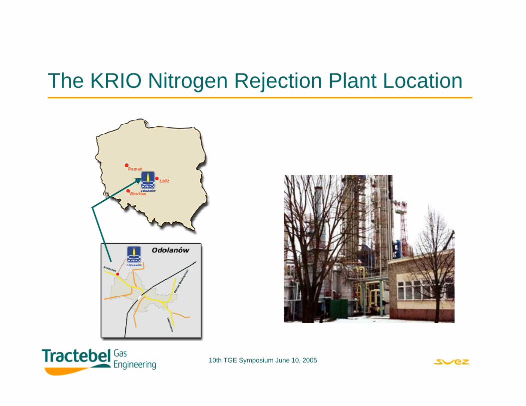
The KRIO Nitrogen Rejection Plant Location
10th TGE Symposium June 10, 2005
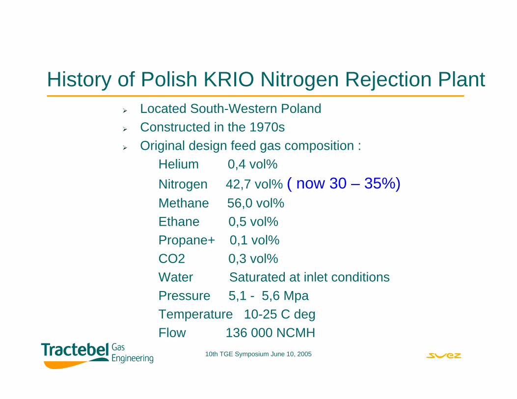
History of Polish KRIO Nitrogen Rejection PlantLocated South-Western PolandConstructed in the 1970sOriginal design feed gas composition :
Helium 0,4 vol%Nitrogen 42,7 vol% ( now 30 – 35%)Methane 56,0 vol%Ethane 0,5 vol%Propane+ 0,1 vol%CO2 0,3 vol%Water Saturated at inlet conditionsPressure 5,1 - 5,6 MpaTemperature 10-25 C degFlow 136 000 NCMH
10th TGE Symposium June 10, 2005
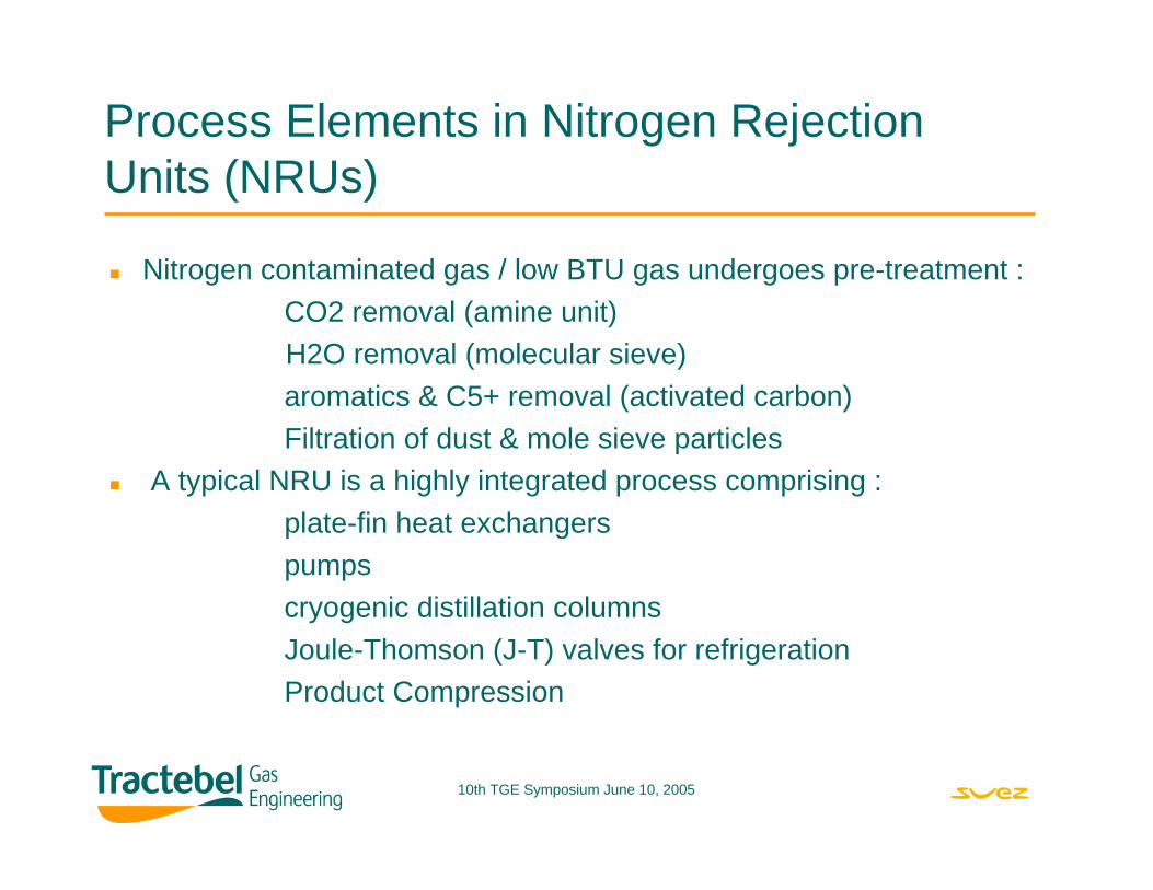
Process Elements in Nitrogen Rejection Units (NRUs)
Nitrogen contaminated gas / low BTU gas undergoes pre-treatment :CO2 removal (amine unit)H2O removal (molecular sieve)aromatics & C5+ removal (activated carbon)Filtration of dust & mole sieve particles
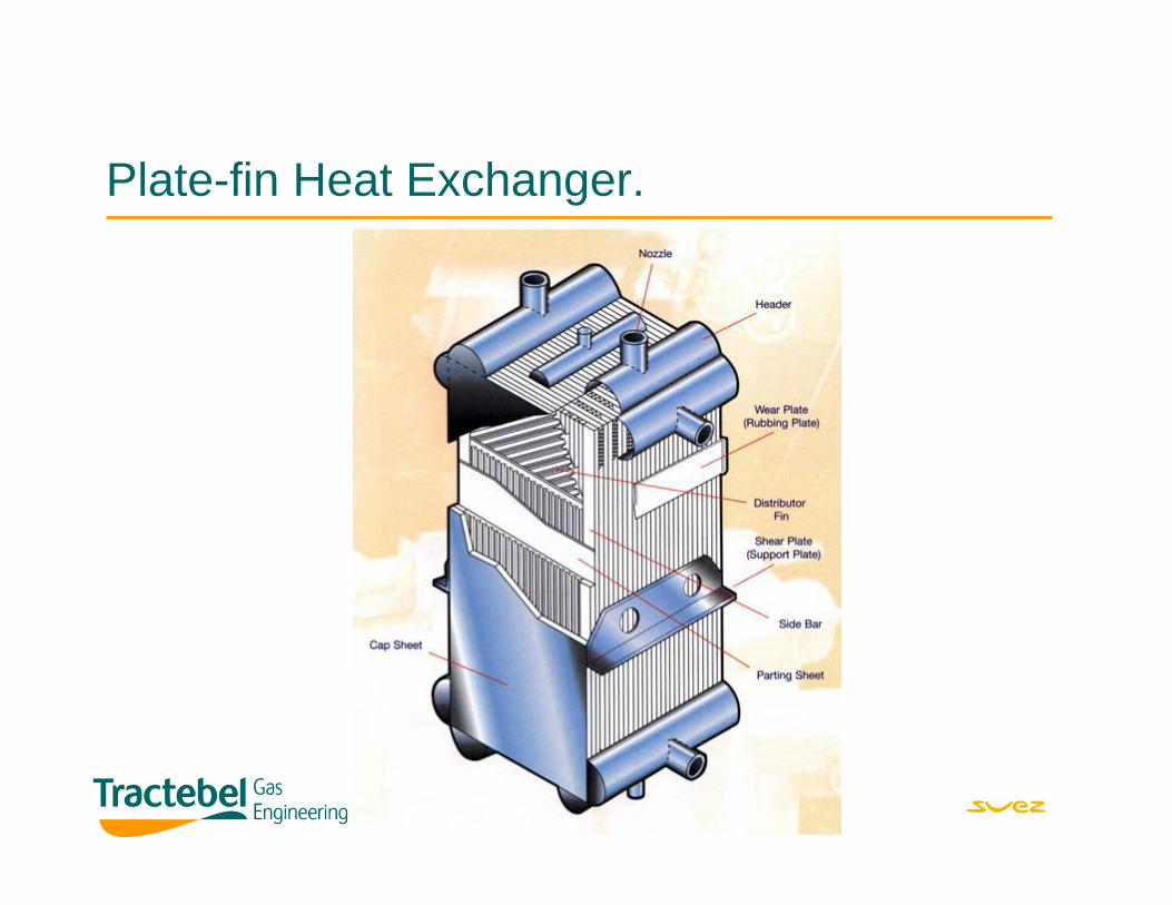
A typical NRU is a highly integrated process comprising :plate-fin heat exchangerspumpscryogenic distillation columnsJoule-Thomson (J-T) valves for refrigerationProduct Compression
10th TGE Symposium June 10, 2005
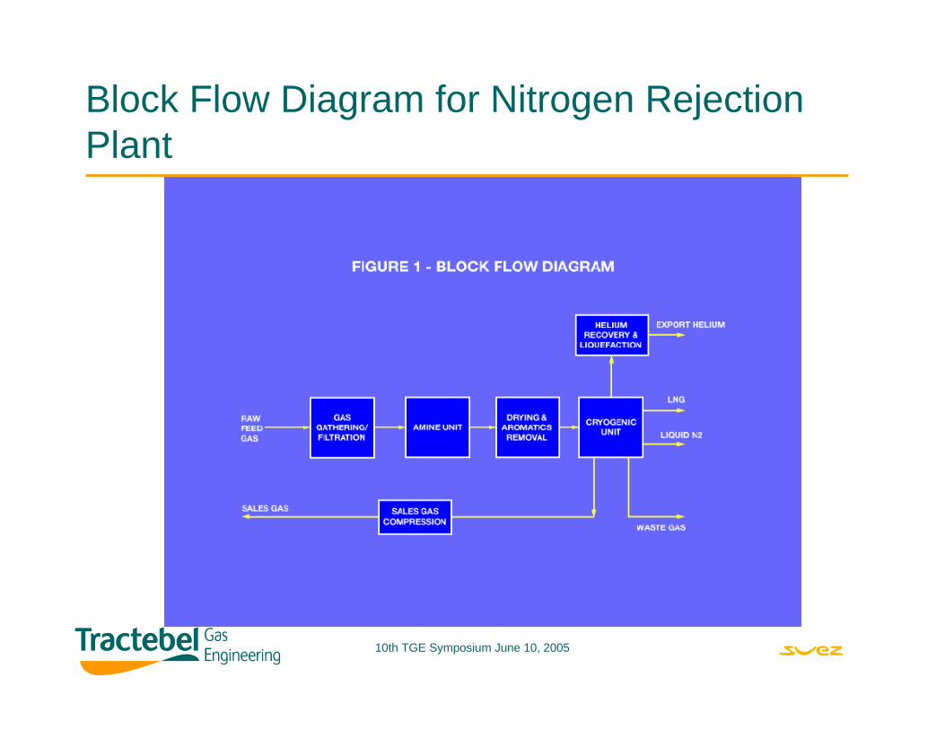
Block Flow Diagram for Nitrogen Rejection Plant
10th TGE Symposium June 10, 2005
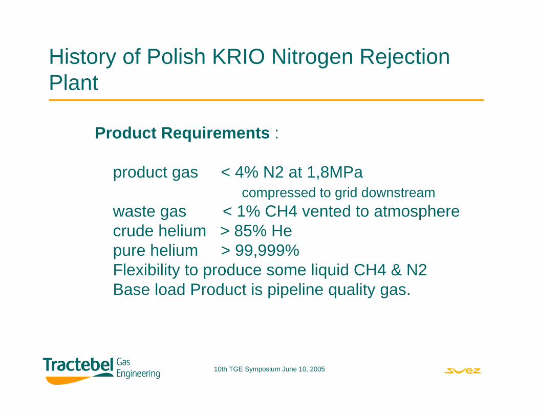
History of Polish KRIO Nitrogen Rejection Plant
Product Requirements :
product gas < 4% N2 at 1,8MPa compressed to grid downstream
waste gas < 1% CH4 vented to atmospherecrude helium > 85% Hepure helium > 99,999%Flexibility to produce some liquid CH4 & N2 Base load Product is pipeline quality gas.
10th TGE Symposium June 10, 2005
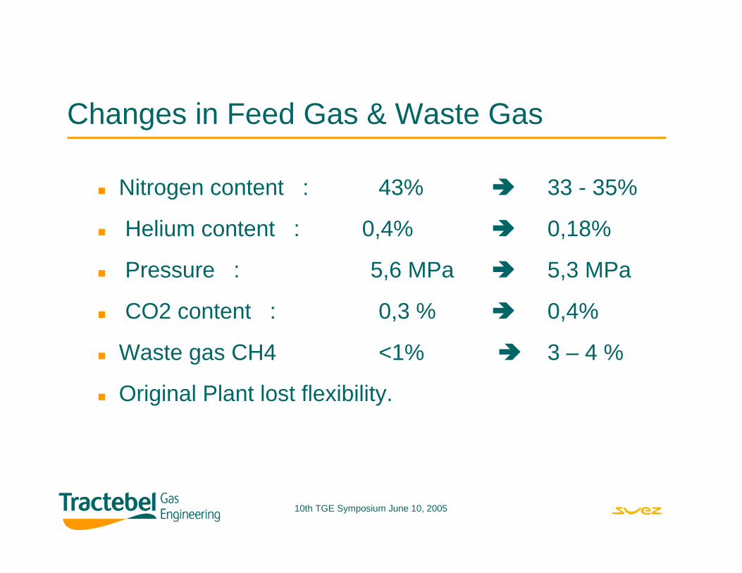
Changes in Feed Gas & Waste Gas
Nitrogen content : 43% 33 - 35%
Helium content : 0,4% 0,18%
Pressure : 5,6 MPa 5,3 MPa
CO2 content : 0,3 % 0,4%
Waste gas CH4 <1% 3 – 4 %
Original Plant lost flexibility.
10th TGE Symposium June 10, 2005
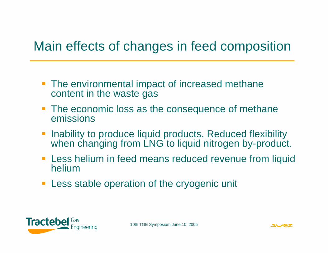
Main effects of changes in feed composition
The environmental impact of increased methane content in the waste gasThe economic loss as the consequence of methane emissionsInability to produce liquid products. Reduced flexibility when changing from LNG to liquid nitrogen by-product.Less helium in feed means reduced revenue from liquid heliumLess stable operation of the cryogenic unit
10th TGE Symposium June 10, 2005
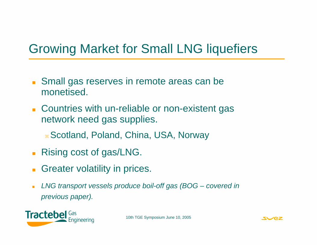
Growing Market for Small LNG liquefiers
Small gas reserves in remote areas can bemonetised.
Countries with un-reliable or non-existent gas network need gas supplies.
Scotland, Poland, China, USA, Norway
Rising cost of gas/LNG.
Greater volatility in prices.
LNG transport vessels produce boil-off gas (BOG – covered in previous paper).
10th TGE Symposium June 10, 2005
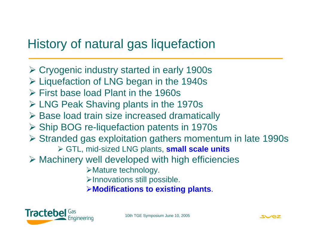
History of natural gas liquefaction
Cryogenic industry started in early 1900sLiquefaction of LNG began in the 1940sFirst base load Plant in the 1960sLNG Peak Shaving plants in the 1970sBase load train size increased dramaticallyShip BOG re-liquefaction patents in 1970sStranded gas exploitation gathers momentum in late 1990s
GTL, mid-sized LNG plants, small scale unitsMachinery well developed with high efficiencies
Mature technology.Innovations still possible.Modifications to existing plants.
10th TGE Symposium June 10, 2005
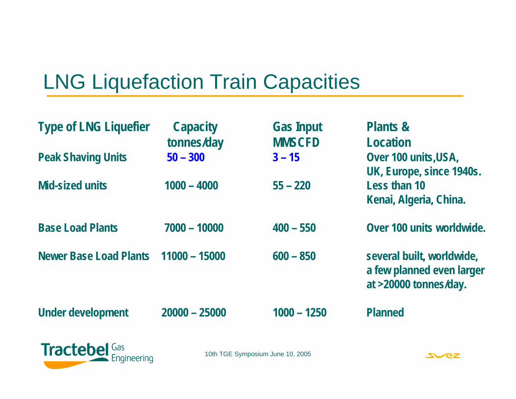
LNG Liquefaction Train Capacities
Type of LNG Liquefier Capacity Gas Input Plants &tonnes/day MMSCFD Location
Peak Shaving Units 50 – 300 3 – 15 Over 100 units,USA,UK, Europe, since 1940s.
Mid-sized units 1000 – 4000 55 – 220 Less than 10Kenai, Algeria, China.
Base Load Plants 7000 – 10000 400 – 550 Over 100 units worldwide.
Newer Base Load Plants 11000 – 15000 600 – 850 several built, worldwide,a few planned even largerat >20000 tonnes/day.
Under development 20000 – 25000 1000 – 1250 Planned
10th TGE Symposium June 10, 2005
Variety of LNG liquefaction CyclesClassical APCI C3 pre-cooled MRC.
Dual MRC, Shell, TEAL & Linde.
Cascade Cycle, Phillips.
Single Fluid, multi-stage Mixed Refrigerant.
Single Stage Mixed Refrigerant, Prico.
Gas expander cycles & Nitrogen Expander cycles.
Novel systems: Acoustic, Vortex Tubes.
Modifications added to existing processes – gas expanders, additional cycles bolted on to existing facilties.
10th TGE Symposium June 10, 2005
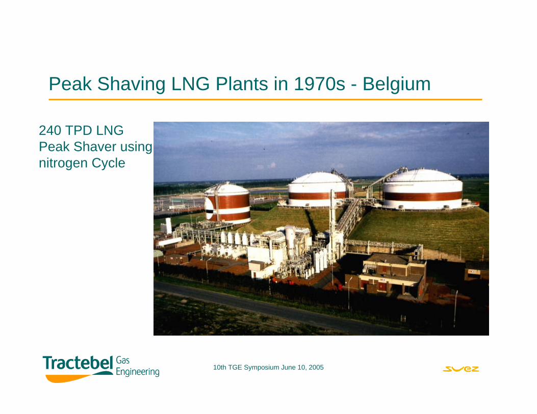
Peak Shaving LNG Plants in 1970s - Belgium
240 TPD LNGPeak Shaver usingnitrogen Cycle
10th TGE Symposium June 10, 2005
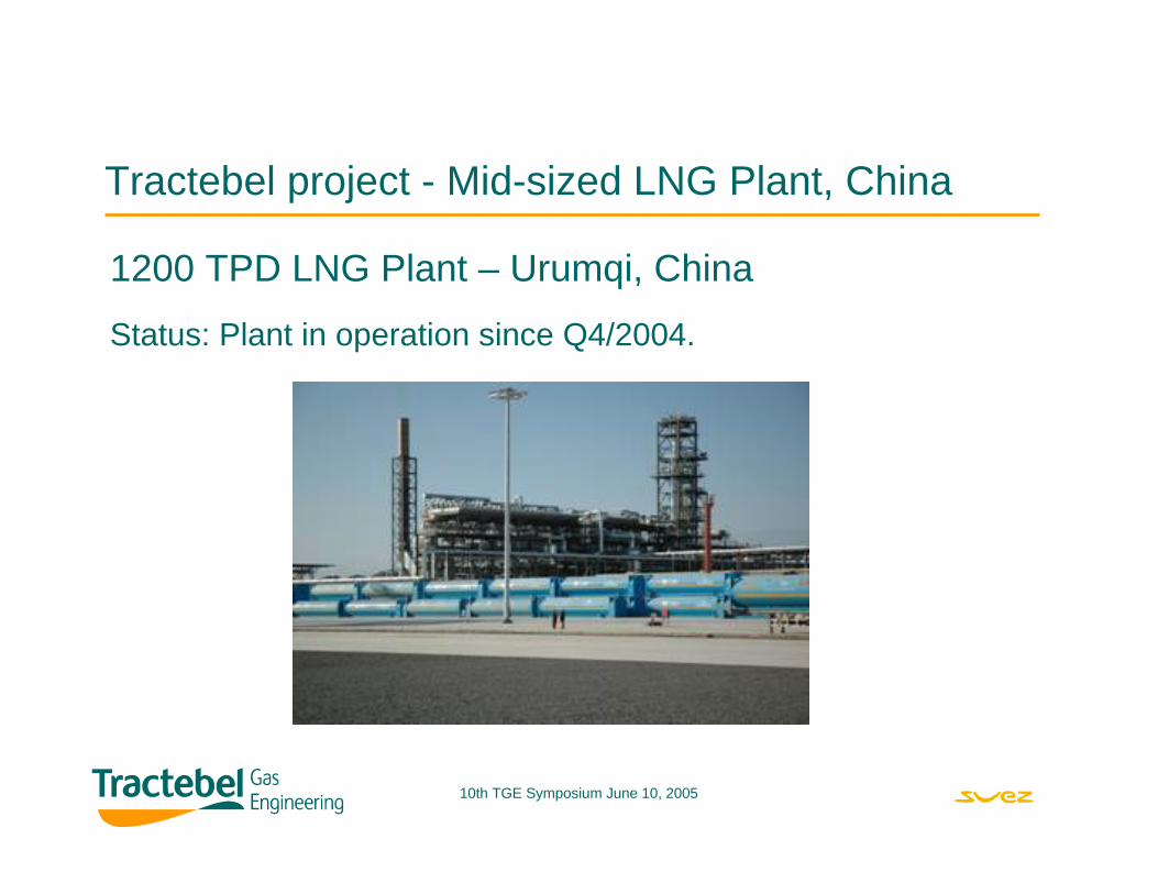
Tractebel project - Mid-sized LNG Plant, China
1200 TPD LNG Plant – Urumqi, China
Status: Plant in operation since Q4/2004.
10th TGE Symposium June 10, 2005
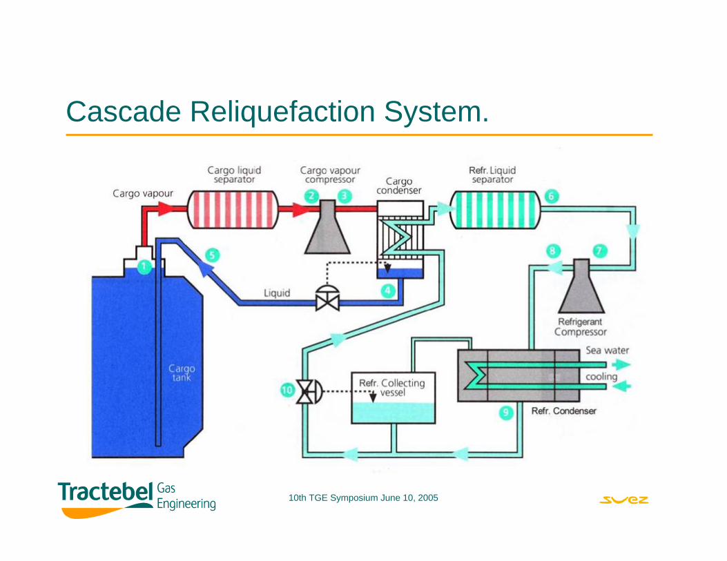
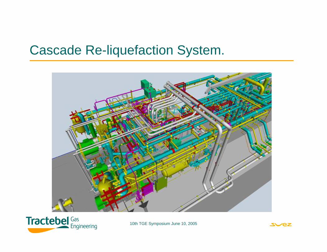
Cascade Reliquefaction System.
10th TGE Symposium June 10, 2005
Cascade Re-liquefaction System.
10th TGE Symposium June 10, 2005
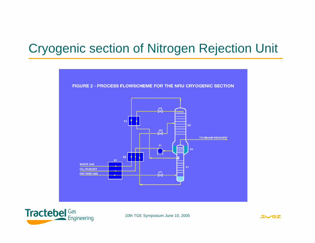
Cryogenic section of Nitrogen Rejection Unit
10th TGE Symposium June 10, 2005
Plate-fin Heat Exchanger.
10th TGE Symposium June 10, 2005
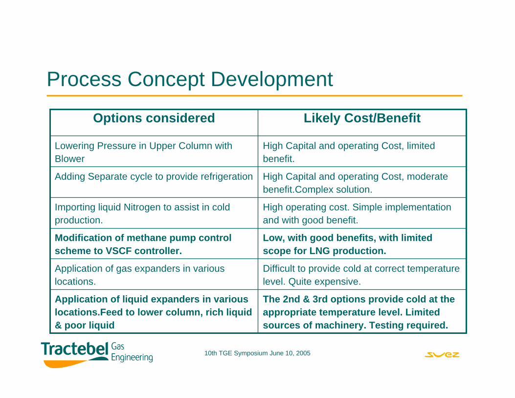
Process Concept Development
High Capital and operating Cost, limitedbenefit.
Lowering Pressure in Upper Column withBlower
The 2nd & 3rd options provide cold at theappropriate temperature level. Limitedsources of machinery. Testing required.
Application of liquid expanders in variouslocations.Feed to lower column, rich liquid & poor liquid
Difficult to provide cold at correct temperaturelevel. Quite expensive.
Application of gas expanders in variouslocations.
Low, with good benefits, with limitedscope for LNG production.
Modification of methane pump controlscheme to VSCF controller.
High operating cost. Simple implementationand with good benefit.
Importing liquid Nitrogen to assist in coldproduction.
High Capital and operating Cost, moderate benefit.Complex solution.
Adding Separate cycle to provide refrigeration
Likely Cost/BenefitOptions considered
10th TGE Symposium June 10, 2005
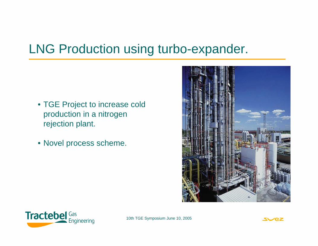
LNG Production using turbo-expander.
• TGE Project to increase cold production in a nitrogen rejection plant.
• Novel process scheme.
10th TGE Symposium June 10, 2005
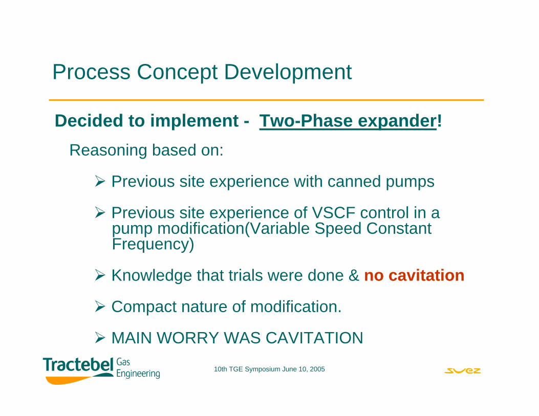
Process Concept Development
Decided to implement - Two-Phase expander!Reasoning based on:
Previous site experience with canned pumps
Previous site experience of VSCF control in a pump modification(Variable Speed ConstantFrequency)
Knowledge that trials were done & no cavitation
Compact nature of modification.
MAIN WORRY WAS CAVITATION
10th TGE Symposium June 10, 2005
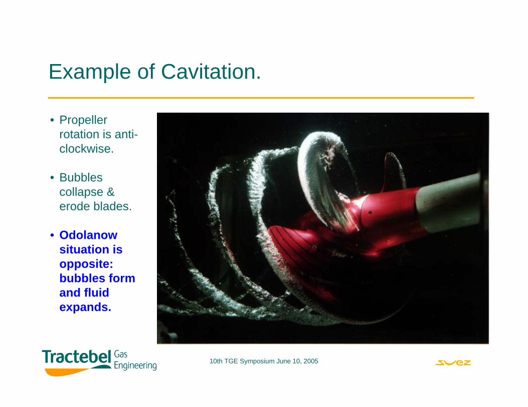
Example of Cavitation.
• Propeller rotation is anti-clockwise.
• Bubbles collapse & erode blades.
• Odolanowsituation is opposite: bubbles form and fluid expands.
10th TGE Symposium June 10, 2005
The challenges in 2-phase turbines.
Cavitation in turbine(95% vapour volume after flash).2-phase flow instability in vertical direction.Bearing fluid.Control of turbine.Local space constraints.Maintaining plant flexibility:
LNG & nitrogen production depending on marketVarying feed composition & need for low CH4 loss in waste gasInternal motor or external motor.
10th TGE Symposium June 10, 2005
LNG liquefaction experience in Poland
Tractebel Project to increase cold production in two nitrogen rejection plants. Result is 60 TPD LNG.
Novel process scheme. A first in the world!!More difficult than BOG re-liquefaction.
EBARA Expansion turbine with flashing flow on two units.
Successful project with test run completed in 2004.
10th TGE Symposium June 10, 2005
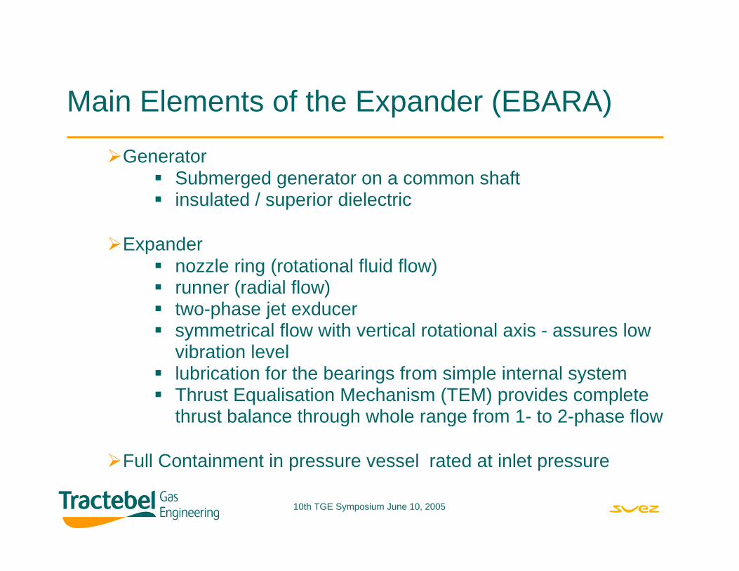
Generator Submerged generator on a common shaftinsulated / superior dielectric
Expander nozzle ring (rotational fluid flow)runner (radial flow)two-phase jet exducersymmetrical flow with vertical rotational axis - assures lowvibration levellubrication for the bearings from simple internal systemThrust Equalisation Mechanism (TEM) provides complete thrust balance through whole range from 1- to 2-phase flow
Full Containment in pressure vessel rated at inlet pressure
Main Elements of the Expander (EBARA)
10th TGE Symposium June 10, 2005
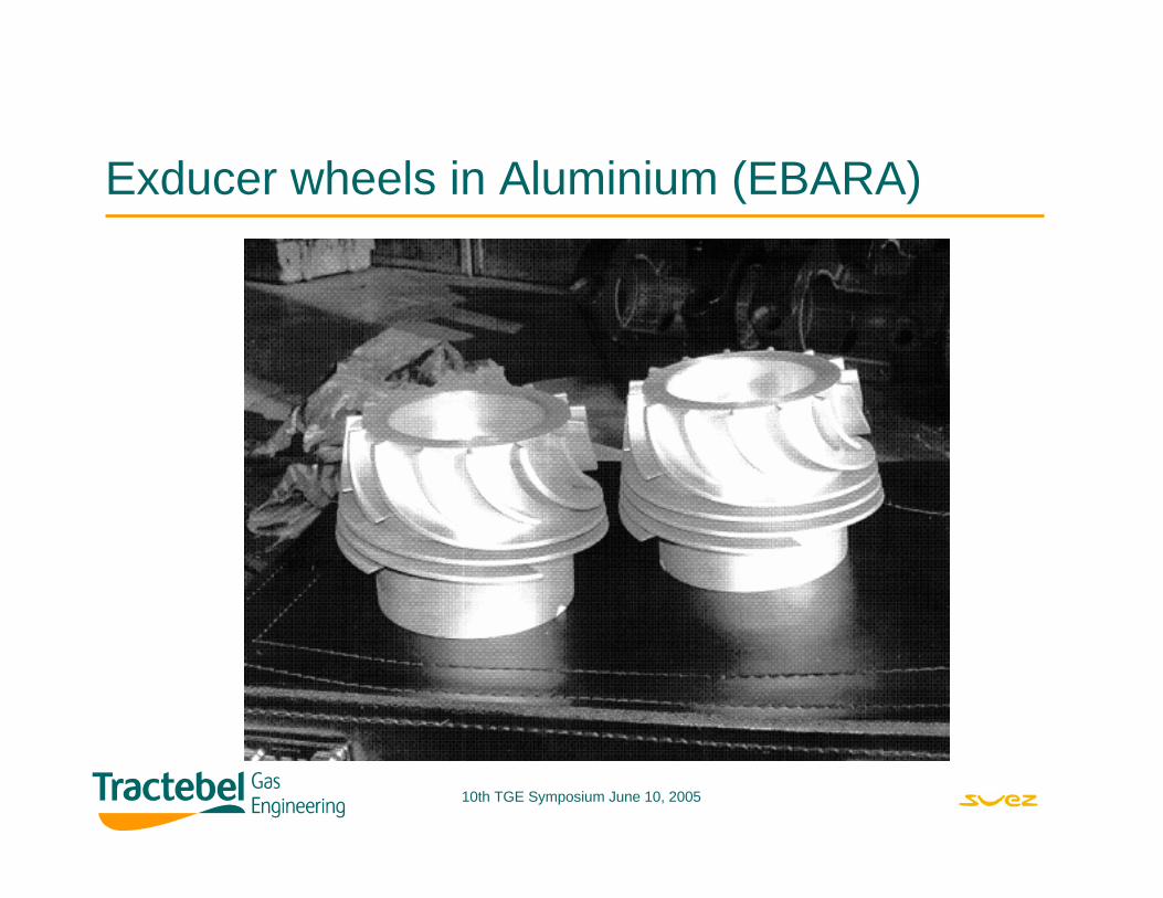
Exducer wheels in Aluminium (EBARA)
10th TGE Symposium June 10, 2005
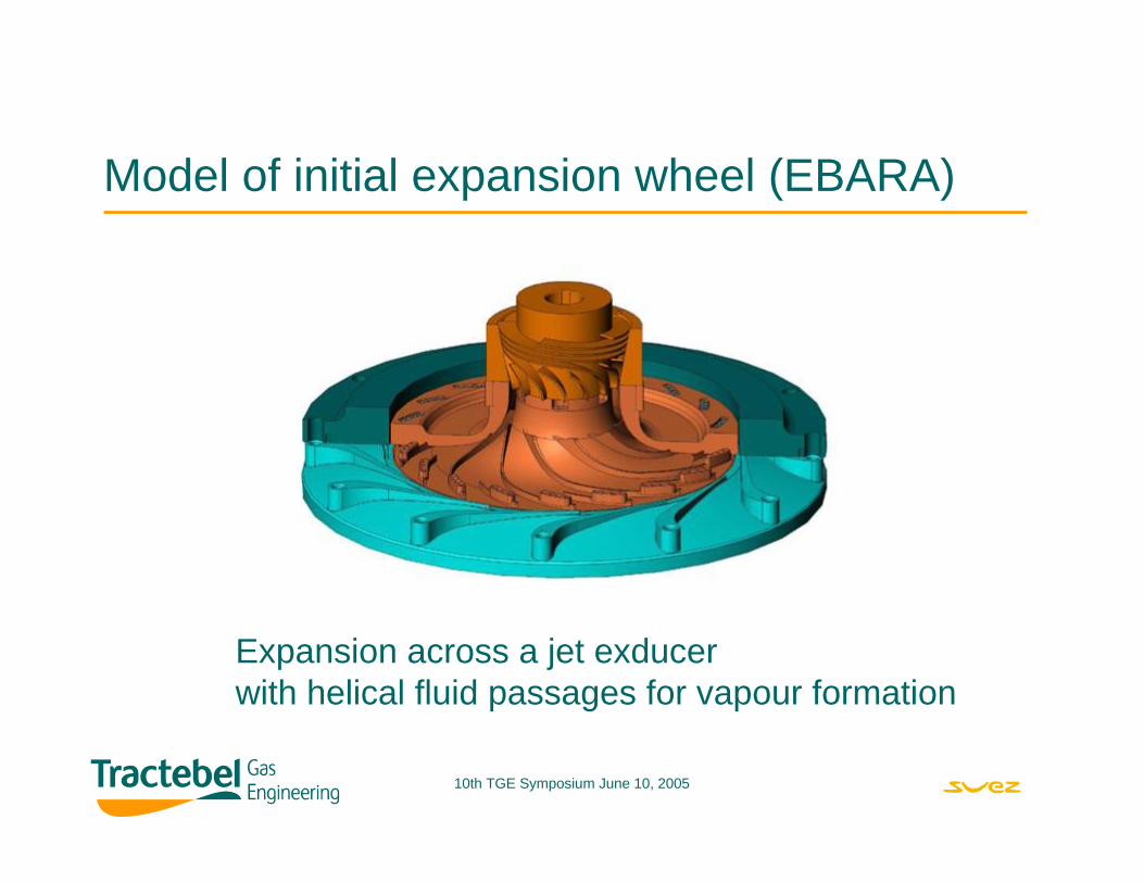
Model of initial expansion wheel (EBARA)
Expansion across a jet exducerwith helical fluid passages for vapour formation
10th TGE Symposium June 10, 2005
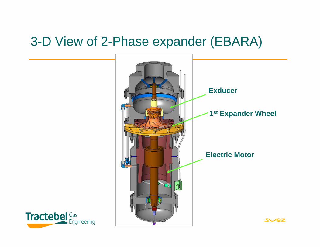
3-D View of 2-Phase expander (EBARA)
Exducer
1st Expander Wheel
Electric Motor
10th TGE Symposium June 10, 2005
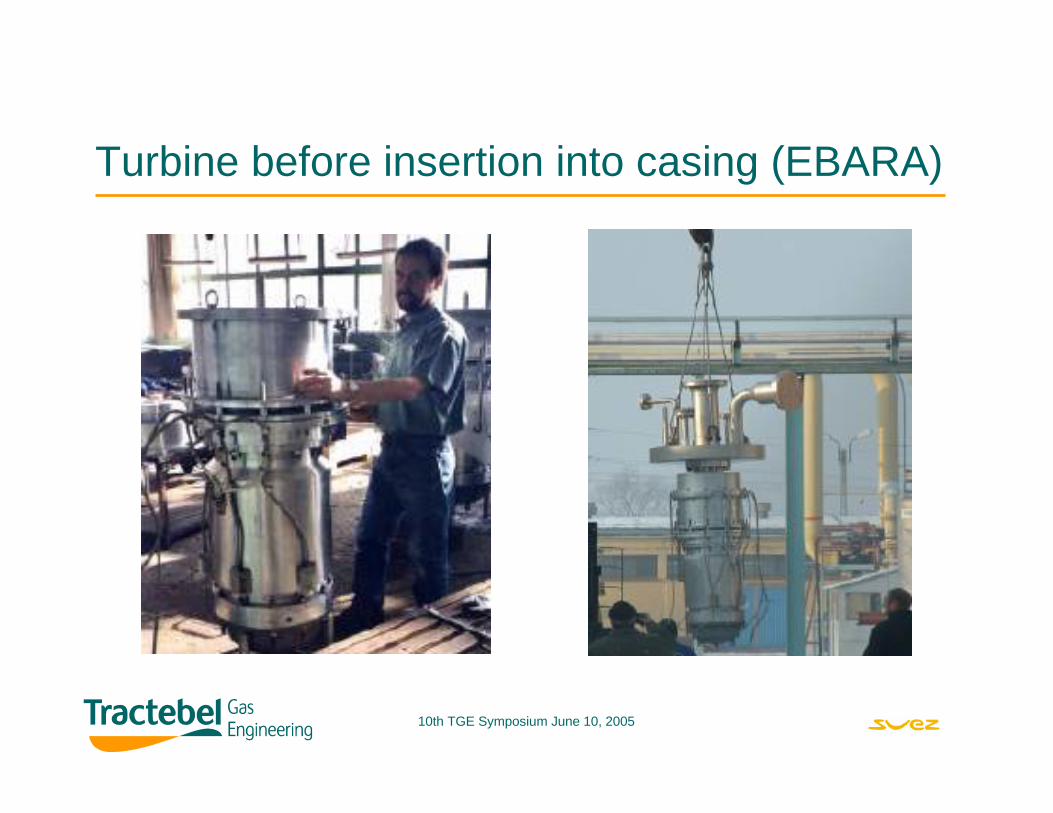
Turbine before insertion into casing (EBARA)
10th TGE Symposium June 10, 2005
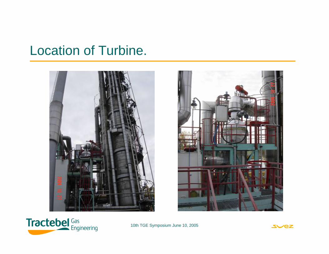
Location of Turbine.
10th TGE Symposium June 10, 2005
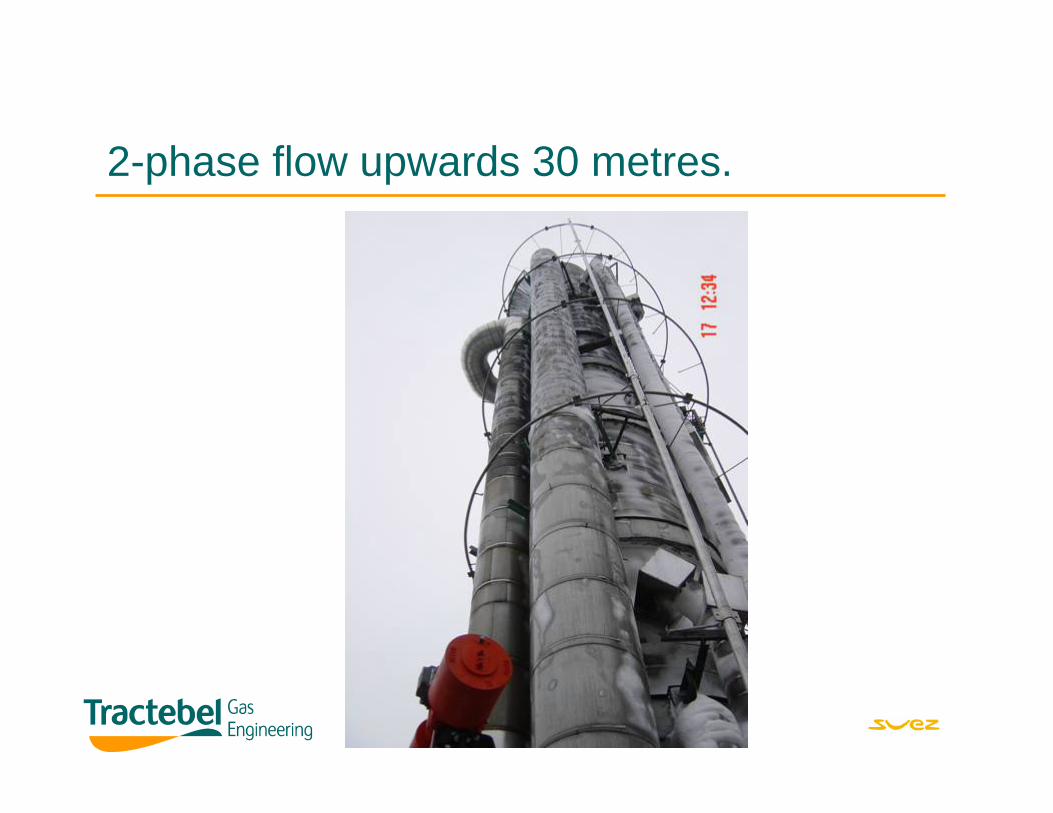
2-phase flow upwards 30 metres.
10th TGE Symposium June 10, 2005
Assessment of Power/Cold Production.• Hydraulic Power available is about 65kW
• In practice 79kW – 85kW extracted at generator terminals.
• In Two-phase terms vapour expansion also contributes energy.
• HYSYS simulation suggests potential power available is over 100kW.
• Therefore, could do even better!
10th TGE Symposium June 10, 2005
Incremental LNG Production Economics.
Assumptions:• LNG cost is at least 5$/MMBtU 2-trains produce 60 TPD LNG• Power Produced is about 80kW per train i.e. 160kW.• Investment is less than 4$ million.
LNG Production yields over 2 million $/year.
Payback in the region of 1 year.
Greater Plant flexibility.
Reduced emissions.
10th TGE Symposium June 10, 2005
Conclusions.Economics was favourable for LNG production and overall plant flexibility.
Several different tests were done for expander wheels to improve efficiency.
Gas expansion energy from flashing flow can be effectively converted to power/cold production.
TGE has an economic solution and broad technical experience to implement such schemes elsewhere.
There is scope for improving the efficiency.
10th TGE Symposium June 10, 2005
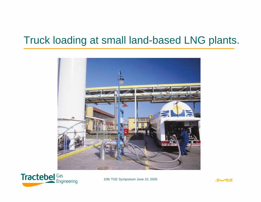
Truck loading at small land-based LNG plants.
10th TGE Symposium June 10, 2005
Thank you for your attention.
Questions welcome


![Small-Mid LNG Plant[1]](https://img.pdfslide.us/doc/110x75/5476085db4af9fa30a8b5faa/small-mid-lng-plant1.jpg)