Embed Size (px)
Citation preview

Content
� Standard EMC measurements
� Highlight railway application limitations
� Unable to predict distortion of digital communication systems
� Novel Time Domain measurement methodology
� Developed TDEMI
� Protect communication systems
� Summary
2

Standard EMC measurements
� EMC Goal: ensure disturbance generated does not interfere with telecommunications and other equipment
� DCS related to Railway safety
� Standard emissions test
� Without movement (QP detector)
� With movement (PK detector - time limitations)
� Measure only some µs at each frequency
� Miss many possible disturbances
� Characterize full-spectrum properly
� Impossible due to measurement receiver architecture
3
� Frequency sweep method (EMI receiver)
� Measurement of time-varying sources is known to be a problem with the frequency domain method

Problems of standard EMC measurements
� In-situ EMC emissions measurements limitations
� Sources of uncertainty
� Don’t know source interference (Railway or elsewhere) special for urban scenarios
� Not possible to use conventional methods due to long measurement time
� frequency domain approach measures each frequency at a different time
� Evaluate all functional modes
� Regenerative breaking
� Railway and transient interferences
� Arching, switching
� occurs randomly
� Cause interferences with Eurobalise or GSM-R
4

Problems of standard EMC measurements
� Radiated transient interferences are broadband impulsive noise
� Frequency sweep measurement or not-full spectrum time domain are not useful
� The level, frequency, duration and interval of the transient interference must be considered
� Eurobalise � 27 MHz, …
� DVB-T � 510 – 690 MHz
� GSM-R � 890 – 960 MHz
0 0.2 0.4 0.6 0.8 1 1.2
x 10-6
-1
-0.8
-0.6
-0.4
-0.2
0
0.2
0.4
0.6
0.8
1
Time
Am
plit
ud
e (
V)
0 2 4 6 8 10
x 108
2
4
6
8
10
12
x 10-7
Frequency (Hz)
Tim
e
-150
-140
-130
-120
-110
-100
dBVTime-domain transient measurement
5

Problems of standard EMC measurements
� Standard EMC evaluation
6
� Defined for analogue systems
� Frequency sweep measurements
� QP detector related with human
perception on analogue
communication systems
� Signal-to-Noise-Ratio (SNR) is the
main figure of merit
� Fixed measuring BW (120 kHz
from 30 MHz to 1 GHz)
30 40 60 80 100 200 400 600 1000
0
10
20
30
40
50
60
dB
µV
/mMHz
0 2 4 6 8 10
x 108
2
4
6
8
10
12
x 10-7
Frequency (Hz)
Tim
e
-150
-140
-130
-120
-110
-100
� Confuse broadband impulse noise with narrow
band interference
� Only capture repetitive interferences when the
sweep is synchronized with the interference

Standard EMC meas: Protect communication systems
� Standard measurement and evaluation
� Cannot relate measurement with interference produced (PK, QP, BW,…)
� Underestimate interference � Not properly captured (transient)
� Overestimate interference � Captured (pessimistic worst-case)
� New meas & evaluation to protect communication systems needed
� Evaluate real effects on digital communication systems
� Protect GSM-R, Eurobalise, digital broadcasting,… from unwanted railway emissions
7
Movement PK
measurement
• Interference
Probability
distribution
• APD � Bit-Error-
Probability (BEP)
-110 -105 -100 -95 -90 -85 -80 -75 -70 -65 -6010
-7
10-6
10-5
10-4
10-3
10-2
10-1
100
Power (dBm)
Pro
ba
bili
ty
RxQUAL1
RxQUAL2
RxQUAL3
RxQUAL4
RxQUAL5
RxQUAL6
RxQUAL7
SLR interference
SHR interference
No interference
30 40 60 80 100 200
0
10
20
30
40
50
60
dB
µV
/m
MHz
• Limit line
• SNR
• Analogue sys.

Novel Time Domain EMI measurement
� Developed TDEMI
� Transient interference measurements
� Multiple instantaneous measurements
� Interference decomposition
� Protect Digital communication systems
� Employing time-domain captures
� IQ and APD
8

≡
Developed Time-Domain EMI
� Based on: Scope capture + Post-
processing
� Excellent results compared with
EMI receiver (8 bits OSC)
� Accuracy and dynamic range
� Obtain Full spectrum with a
single measurement
� Ideal for unique event interferences
� Evaluate all different EUT modes
100 1000-10
0
10
20
30
40
50
60
70
80
Frequency (MHz)E
(dBµ
V/m
)
EMI Test receiver
TDEMI system
0 0.01 0.02 0.03 0.04 0.05 0.06 0.07-0.1
-0.05
0
0.05
0.1
0.15
Time (µs)
Voltage (
V)
9

Developed Time-Domain EMI
� Compact TDEMI system
� Laptop + Scope
� Measurement time decreased.
� PK and AVG < 30 s from 150 kHz to 30 MHz
� The spectral estimation single time-domain acquisition
� The entire EMI frequency spectrum correspond to the same time frame
� Simultaneous measurements (4 channels)
� Conducted, radiated, …
� Low cost and portable (battery) 1 10 3010
20
30
40
50
60
701 µs Rectangular pulse @ 1 kHz
Voltage (
dBµ
V)
Frequency (MHz)1 10 30
10
20
30
40
50
60
70
80
901 µs Rectangular pulse @ 100 kHz
Voltage (
dBµ
V)
Frequency (MHz)
GCEM TDEMI
EMI Receiver
GCEM TDEMI
EMI Receiver
10

Developed TDEMI for transient interferences
0 1 2 3 4 5
x 10-3
-1000
-500
0
500
1000
Time (s)
Voltage(m
V)
Channel A
� Transient interference measurements
� Acquisitions are triggered by a certain
event or by an external signal.
� Capture transients is possible and easy
� Perfect for in-situ EMI assessments
� Evaluate all functional modes
� Synchronize measurement
11

Developed TDEMI: multiple instantaneous measurements
� Several input channels
� Multiple measurements at the same time
� NF triggering – FF capture
� EMI measurements are instantaneous
� Synchronize measurement with transient
� Up to 4 channels for simultaneous
measurements
Voltage
(m
V)
Voltage (
mV
)
FF capture NF capture
12
Frequency (MHz)
100 230
TDEMI+NF Trigger

Developed TDEMI: multiple instantaneous measurements
� Same instant multiple captures
� Conducted emissions
� Measure all lines at the same time
� Real common-mode and differential-
mode disturbance measurement
� Simultaneous Electric and Magnetic
field probe (TD operation is needed)
13
0 0.05 0.1 0.15 0.2 0.25 0.3 0.35 0.4
0
0.05
0.1
0 0.05 0.1 0.15 0.2 0.25 0.3 0.35 0.4
0
0.05
0.1
0.155 0.16 0.165 0.17 0.175 0.18 0.185
0
0.05
0.1
0.155 0.16 0.165 0.17 0.175 0.18 0.185 0.19
0
0.05
0.1

Developed TDEMI: interference decomposition
� Background noise cancellation
� Decomposition of interferences
� Identify transient and CW interference
� Ideal for in-situ measurements
30 100 100025
30
35
40
45
50
55
60
65
70
75
Frequency (MHz)
E-f
ield
(d
Bµ
V/m
)
ESPI
TDEMI
FM broadcasting
GSM jamming signal
Transient EMI
14

Developed TDEMI: interference decomposition
0 0.2 0.4 0.6 0.8 1
-20
0
20
Time (ms)
IMF
1 V
olt
ag
e (
mV
)
Transient Mode
30 100 100020
30
40
50
Frequency (MHz)
IMF
1 E
-fie
ld (
dBµ
V/m
)
0 0.2 0.4 0.6 0.8 1-4
-2
0
2
4
GSM jamming signal
Time (ms)
IMF
2 V
olt
ag
e (
mV
)
0 0.2 0.4 0.6 0.8 1-4
-2
0
2
4
Time (ms)
FM broadcasting
IMF
3 V
olt
ag
e (
mV
)
30 100 1000
20
30
40
50
60
Frequency (MHz)
IMF
3 E
-fie
ld (
dBµ
V/m
)
30 100 1000
30
40
50
60
70
Frequency (MHz)
IMF
2 E
-fie
ld (
dBµ
V/m
)
30 100 100020
25
30
35
40
45
50
55
Frequency (MHz)
E-f
ield
(dBµ
V/m
)
ESPI
IMF1
15
� Capability to isolated different interferences
� Employing Time Domain data
� Impulsive noise
� Transient interference
� GSM jamming
� FM broadcasting

Protect Digital Communication systems
� EMC standards are not useful to
predict interference
� Limit line related with SNR
� Pk and QP measurement
� 120 kHz BW non-sense (developed for
analogue systems)
16
0 200 400 600 800 1000 1200 1400 1600 1800 2000-30
-20
-10
0
10
20
30
Samples
Am
plit
ud
e (
µV
)
30 40 60 80 100 200 400 600 1000
0
10
20
30
40
50
60
dB
µV
/m
MHz
� Employ captured Time Domain data
� Obtain in-phase and quadrature components IQ
at the frequency band of the communication
system
� Obtain the amplitude probability distribution
(APD) at any desired frequency band
� Allow us to fulfil the requirements defined in the
directive

TDEMI: Protect Digital Communication systems
� GSM-R system interfered by radiated transients
� With standard methodology difficult (near to impossible) to capture
properly transient interference
� It is not feasible to relate Pk or QP meas with the error produced to
GSM-R system
� Time domain data � IQ capture and simulation
� IQ obtained at the frequency band of the DCS
� Simulate GSM-R sys. to obtain BER in presence of transient
17
0 200 400 600 800 1000 1200 1400 1600 1800 2000-30
-20
-10
0
10
20
30
Samples
Am
plit
ud
e (
µV
)
IF Data
IQ Data Possible to obtain BER

TDEMI: Protect Digital Communication systems
� Results employing APD diagram including GSM specification limits
� Easy to identify the worst case of interference
� Predict RXQUAL level and BER from APD diagram
18
-110 -105 -100 -95 -90 -85 -80 -75 -70 -65 -6010
-7
10-6
10-5
10-4
10-3
10-2
10-1
100
Power (dBm)
Pro
ba
bili
ty
RxQUAL1
RxQUAL2
RxQUAL3
RxQUAL4
RxQUAL5
RxQUAL6
RxQUAL7
SLR interference
SHR interference
No interference
Interference
APD diagram error
estimation
BER RXQUAL
SHR(High Rate) 1.8 % RXQUAL_4
SLR (Low Rate) 0.09 % RXQUAL_0
RXLevel
������ , ������ ≡��
, ����
� APD - BER limits:
� Probability error requirements
� Amplitude received (RXLevel)
� Modulation scheme

TDEMI: Protect Digital Communication systems
� Results obtained
� We can predict the degradation suffered by GSM with previous TD measurements
� Excellent results achieved
� Negligible interference for SLR
� RXQUAL_4 result for SHR
� APD really useful � fast capacity interpret results and quantify degradation
19
Interference
Measured Signal quality
by GSM MS Test unit
DCS simulation
methodology
APD error
estimation
RXQUAL BER RXQUAL BER RXQUAL BER
SHR (High Rate) RXQUAL_4 2.07 % RXQUAL_4 2.39 % RXQUAL_4 1.8 %
SLR (Low Rate) RXQUAL_0 0.01 % RXQUAL_0 0.04 % RXQUAL_0 0.09 %
-110 -105 -100 -95 -90 -85 -80 -75 -70 -65 -6010
-7
10-6
10-5
10-4
10-3
10-2
10-1
100
Power (dBm)
Pro
ba
bili
ty
RxQUAL1
RxQUAL2
RxQUAL3
RxQUAL4
RxQUAL5
RxQUAL6
RxQUAL7
SLR interference
SHR interference
No interference

Summary
� Standard EMC measurements are not effective
� Only frequency domain data available, QP (120 kHz) or PK
� Miss many information specially from transients
� Impossible to relate with BER
� Developed time domain methodologies
� Instantaneous acquisition
� Multiple channels
� Ideal for transient interferences (triggering)
� Decomposition of interference: cancel background noise � ideal for in-situ
� Predict the degradation of communication systems including transient
interference
� IQ components
� APD (Amplitude Probability Distribution)
20

BcnRail INNOVA
Proyectos estratégicos ferroviarios de I+D+i
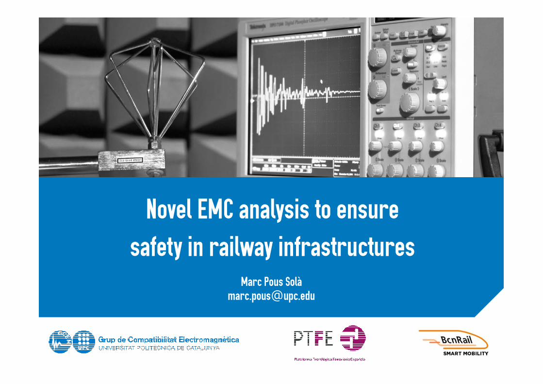
Novel EMC analysis to ensure safety in railway infrastructures
Marc [email protected]
GCEM-UPC
Nº Expediente: PTR-2014-0351
21