Embed Size (px)
Citation preview
NOE turm®
Stand: 08.2011
Aufbau- undVerwendungsanleitung
System A
The Formwork
Assembly and Operating Manual
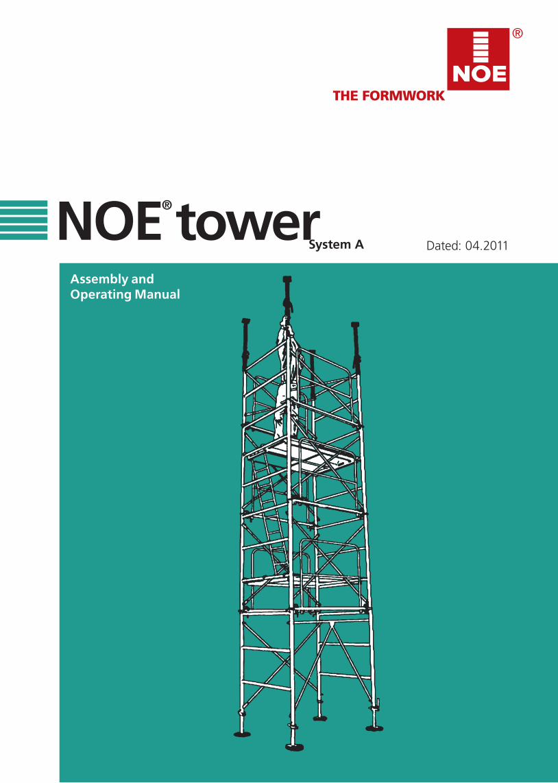
Dated: 04.2011NOE® tower
System A

2 Dated: 04.2011 NOEturm system A We reserve the right to make technical modifications.
We reserve the right to make technical modifications. NOEturm system A Dated: 04.2011 3
Contents
1. Safety advice, GSV guidelines . . . . . . . . . . . . . . . . . . . 4
2. Assembly insructions . . . . . . . . . . . . . . . . . . . . . . . . . . . 52.1 Erecting the tower . . . . . . . . . . . . . . . . . . . . . . . . . . . . . . . 52.2 Concreting . . . . . . . . . . . . . . . . . . . . . . . . . . . . . . . . . . . . . . 72.3 Dismantling the tower . . . . . . . . . . . . . . . . . . . . . . . . . . . . 7
3. Connecting the tower elements . . . . . . . . . . . . . . . . . 7
4. Foot spindle and plate . . . . . . . . . . . . . . . . . . . . . . . . . . 8
5. Spindle, head support and fork head . . . . . . . . . . . . 8
6. Tower heights and permissible loads . . . . . . . . . . . . 9
7. moving by crane . . . . . . . . . . . . . . . . . . . . . . . . . . . . . . . . 10
8. Formwork construction . . . . . . . . . . . . . . . . . . . . . . . . . 10
9. Individual parts . . . . . . . . . . . . . . . . . . . . . . . . . . . . . . . . 11
4 Dated: 04.2011 NOEturm system A We reserve the right to make technical modifications.
GSV Guidelines Important information regarding the intended useand safe application of formwork and falsework
The contractor is responsible for drawing up a comprehensive risk assessment and a set of installation instructions. The latter is not usually identical to the assembly instructions.
• Risk Assessment The contractor is responsible for the compilation, documentation, implementation and revision of a risk assessment for each construction site. His employees are obliged to implement the measures resulting from this in accordance with all legal requirements.• Installation Instructions The contractor is responsible for compiling a written set of installation instructions. The assembly instructions forms part of the basis for the compila-tion of a set of installation instructions. • Assembly Instructions Formwork is technical work equipment which is in-tended for commercial use only. The intended use must take place exclusively through properly trained personnel and appropriately qualified supervising personnel. The assembly instructions are an integral component of the formwork construction. They com-prise at least safety guidelines, details on the stan-dard configuration and intended use, as well as the system description. The functional instructions (standard configuration) contained in the assembly instructions are to be complied with as stated. Enhancements, deviations or changes represent a potential risk and therefore require separate verification (with the help of a risk assessment) or a set of installation instructions which comply with the relevant laws, standards and safety regulations. The same applies in those cases where formwork and/or falsework components are provided by the contractor. • Availability of the Assembly Instructions The contractor has to ensure that the assembly in-structions provided by the manufacturer or formwork supplier are available at the place of use. Site per-sonnel are to be informed of this before assembly and use takes place, and that they are available at all times. • Representations The representations shown in the assembly instruc-tions are, in part, situations of assembly and not always complete in terms of safety considerations. The safety installations which have possibly not been shown in these representations must nevertheless be available.
• Storage and TransportationThe special requirements of the respective formwork con-structions regarding transportation procedures as well as storage must be complied with. By way of example, name the appropriate lifting gear to be used. • Material Check Formwork and falsework material deliveries are to be checked on arrival at the construction site/place of destina-tion as well as before each use to ensure that they are in perfect condition and function correctly. Changes to the formwork materials are not permitted. • Spare Parts and Repairs Only original components may be used as spare parts. Re-pairs are to be carried out by the manufacturer or authorized repair facilities only. • Use of Other Products Combining formwork components from different manufac-turers carries certain risks. They are to be individually veri-fied and can result in the compilation of a separate set of assembly instructions required for the installation of the equipment. • Safety Symbols Individual safety symbols are to be complied with. Examples:
• Miscellaneous Technical improvements and modifications are subject to change without notice. For the safety-related application and use of the products, all current country-specific laws, standards as well as other safety regulations are to be complied with without excep-tion. They form a part of the obligations of employers and employees regarding industrial safety. This results in, among other things, the responsibility of the contractor to ensure the stability of the formwork and falsework construc-tions as well as the structure during all stages of construc-tion. This also includes the basic assembly, dismantling and the transport of the formwork and falsework constructions or their components. The complete construction is to be checked during and after assembly.
Version: 28.08.2009 Copyright: Güteschutzverband Betonschalungen e.V. PO BOX 10 41 60 40852 Ratingen Germany
Visual check: the intended operation is to be carried out through a visual check. Note: supplementary information for safe, correct and professional execution of work activities.
Safety information: non-compliance can lead to damage to materials or risk to the health of site personnel (also life)
We reserve the right to make technical modifications. NOEturm system A Dated: 04.2011 5
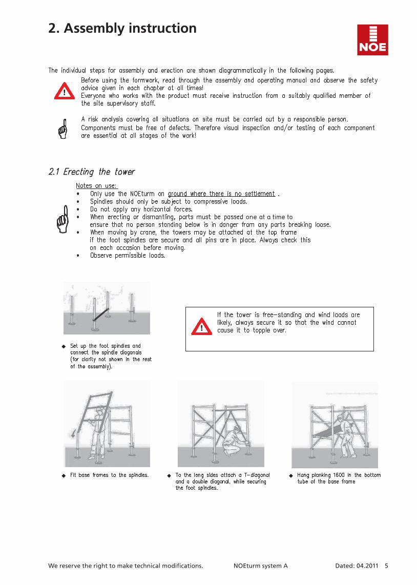
2. Assembly instruction
one at a time to
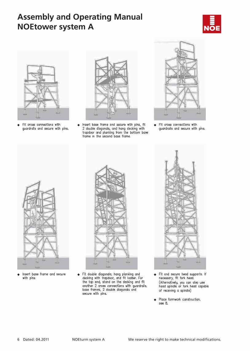
Assembly and Operating ManualNOEtower system A
6 Dated: 04.2011 NOEturm system A We reserve the right to make technical modifications.
We reserve the right to make technical modifications. NOEturm system A Dated: 04.2011 7
Assembly and Operating ManualNOEtower system A
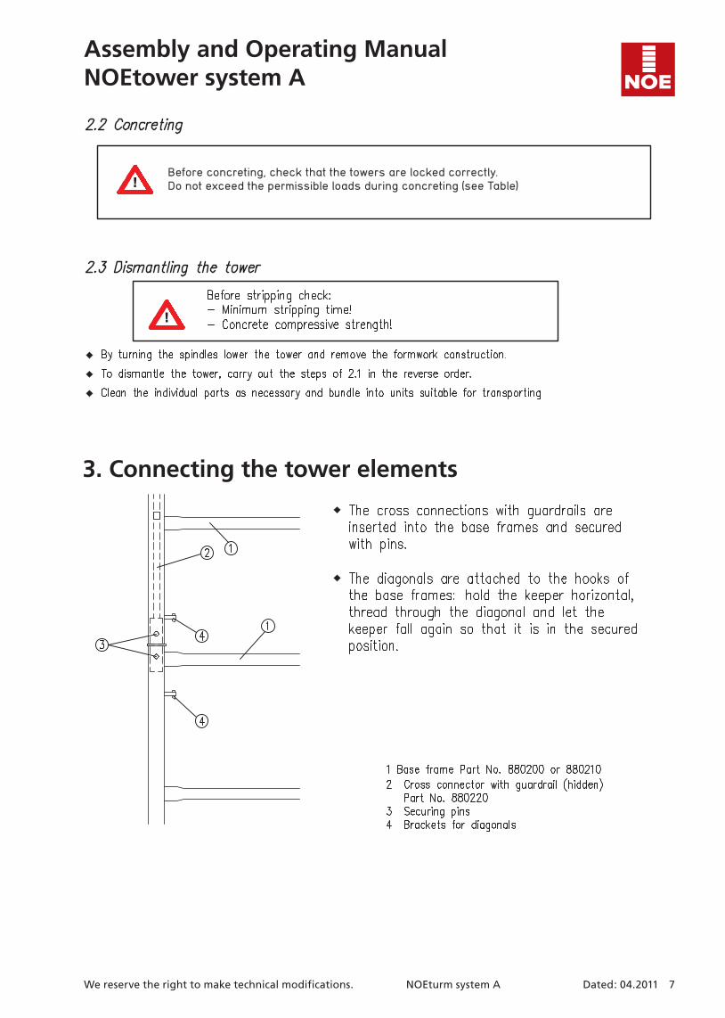
3. Connecting the tower elements
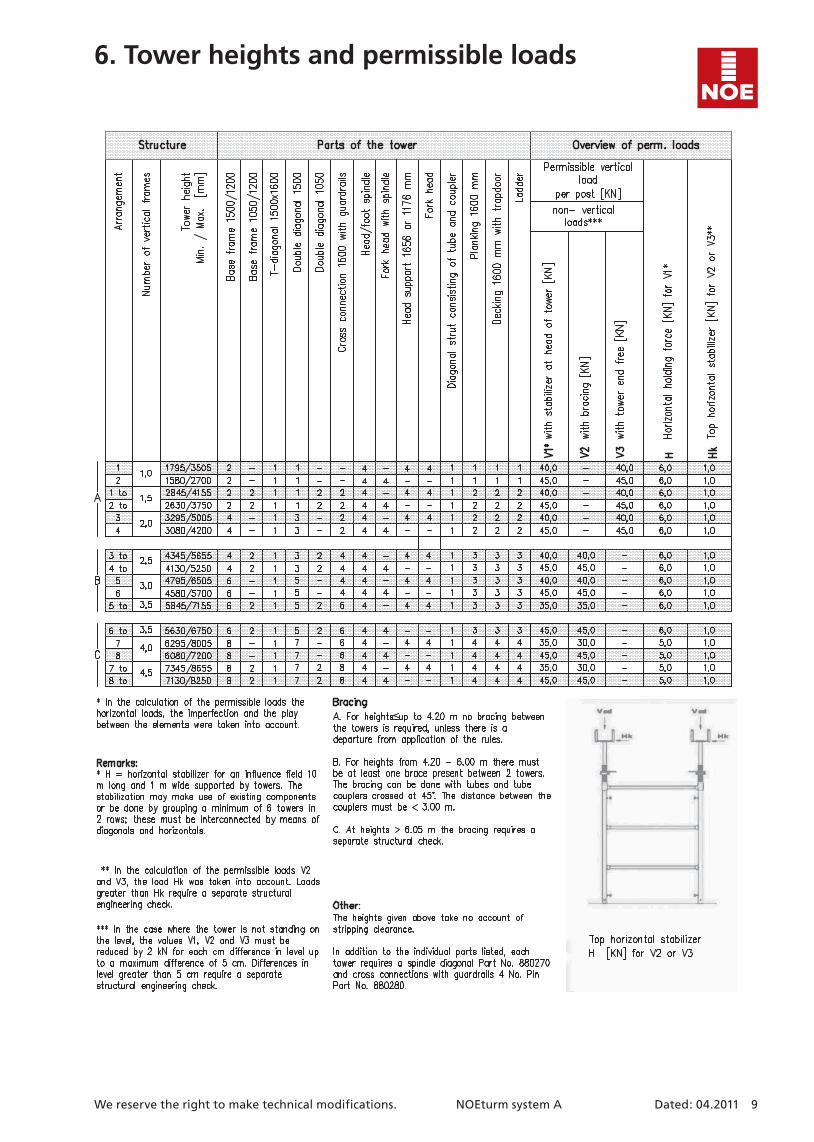
Before concreting, check that the towers are locked correctly. Do not exceed the permissible loads during concreting (see Table)
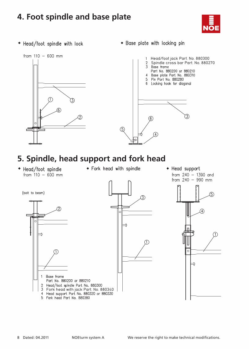
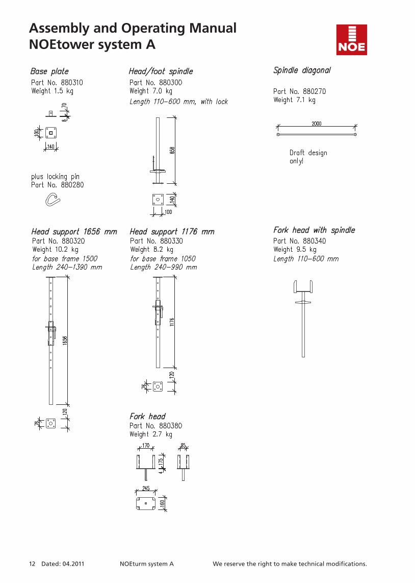
Head/foot jack Part. No. 880300Spindle cross bar Part. No. 880270
Fork head with jack Part. No. 880340
8 Dated: 04.2011 NOEturm system A We reserve the right to make technical modifications.
4. Foot spindle and base plate
5. Spindle, head support and fork head
We reserve the right to make technical modifications. NOEturm system A Dated: 04.2011 9
6. Tower heights and permissible loads
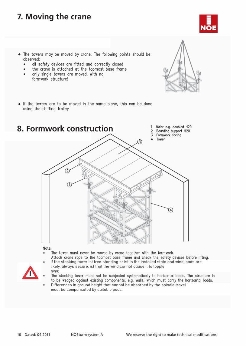
If the stacking tower ist free-standing or ist in the installed state and wind loads are likely, always secure, ist that the wind cannot cause it to toppleover.
Differences in ground height that cannot be absorbed by the spindle travelmust be compensated by suitable pads.
10 Dated: 04.2011 NOEturm system A We reserve the right to make technical modifications.
7. Moving the crane
8. Formwork construction
If the stacking tower ist free-standing or ist in the installed state and wind loads are likely, always secure, ist that the wind cannot cause it to toppleover.
Differences in ground height that cannot be absorbed by the spindle travelmust be compensated by suitable pads.
We reserve the right to make technical modifications. NOEturm system A Dated: 04.2011 11
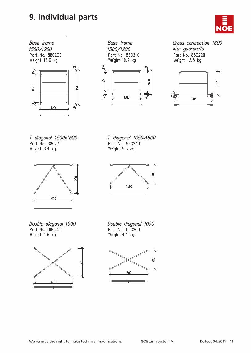
9. Individual parts
Assembly and Operating ManualNOEtower system A
12 Dated: 04.2011 NOEturm system A We reserve the right to make technical modifications.
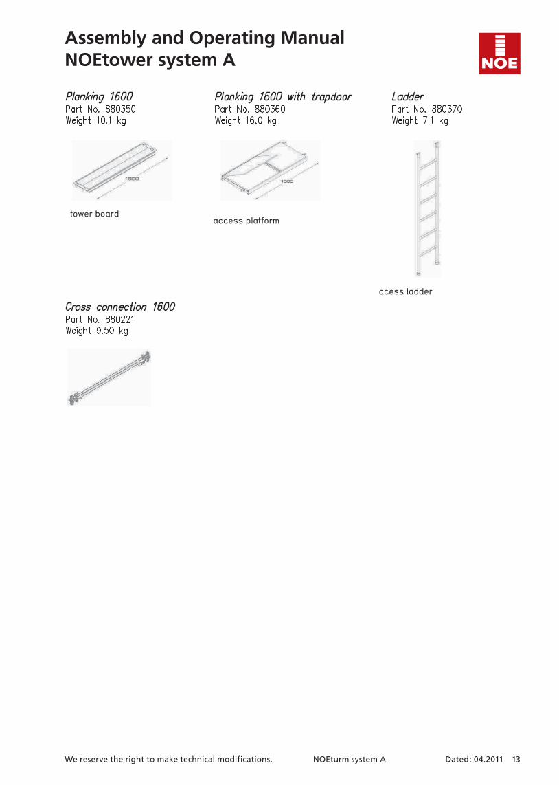
tower board
acess ladder
access platform
We reserve the right to make technical modifications. NOEturm system A Dated: 04.2011 13
Assembly and Operating ManualNOEtower system A

Assembly and Operating ManualNOEtower system A
14 Dated: 04.2011 NOEturm system A We reserve the right to make technical modifications.

We reserve the right to make technical modifications. NOEturm system A Dated: 04.2011 15
Assembly and Operating ManualNOEtower system A
NS/e XXXXXX XXX 09.11Subject to technical modifications.
AustriaNOE-Schaltechnik www.noe-schaltechnik.at [email protected]
BelgiumNOE-Bekistingtechniek n.v. www.noe.be [email protected]
BrasilMills do Brasil Estruturas e Serviços Ltda www.mills.com.br [email protected]
BulgariaNOE-Schaltechnik www.noebg.com [email protected]
CroatiaNOE oplatna tehnika d.o.o. www.noe.hr [email protected]
Czech RepublicISD-NOE www.isd-noe.cz [email protected]
FranceNOE-France www.noefrance.fr [email protected]
NetherlandsNOE-Bekistingtechniek b.v. www.noe.nl [email protected]
PolandNOE-PL Sp. Zo.o. www.noe.com.pl [email protected]
RussiaNOE St. Petersburg [email protected]
SerbiaNOE Sistemske Oplate d.o.o. www.noe-scg.com [email protected]
SlovakiaISD-NOE www.isd-noe.sk [email protected]
SwitzerlandNOE-Schaltechnik www.noe.ch [email protected]
NOE-Schaltechnik Georg Meyer-Keller GmbH + Co. KGKuntzestr. 72, 73079 Suessen, GermanyTel. +49 7162 13-1Fax +49 7162 [email protected]
The Formwork