Embed Size (px)
Citation preview

New Hampshire Weatherization
Standards
Low-Income Weatherization Assistance Program
March 2005

New Hampshire Weatherization
Standards
Low-Income Weatherization Assistance Program
March 2005
State of New Hampshire Office of Energy and Planning
57 Regional Drive Concord, NH 03301
603-271-2155
MaryAnn Manoogian Director
Andrew Gray
Weatherization Program Manager 603-271-6359
New Hampshire Weatherization Standards, March 2005 i
Acknowledgements This project was managed by Andrew Gray, New Hampshire Weatherization Program Manager. The primary contractor was Rick Karg of R.J. Karg Associates, Topsham, Maine. The details of the New Hampshire Weatherization Standards were selected as best practices for the northern United States and adapted for the New Hampshire weatherization program. This document was written by Rick Karg with the assistance of Andrew Gray and members of the New Hampshire weatherization technical committee. Members of this committee included: Charlie Wolfe, Weatherization Director, Strafford County Community Action Committee Dan Girard, Energy Auditor, Southern New Hampshire Services Peter Bilodeau, Energy Auditor, Tri-County Community Action Rob Pettis, Energy Auditor, Tri-County Community Action These Standards were reviewed and discussed by Andrew Gray, weatherization directors, energy auditors, foremen, agency employed crew, and contractors. All contributed to the quality of these Standards.
New Hampshire Weatherization Standards, March 2005 ii
Index Tab Reference
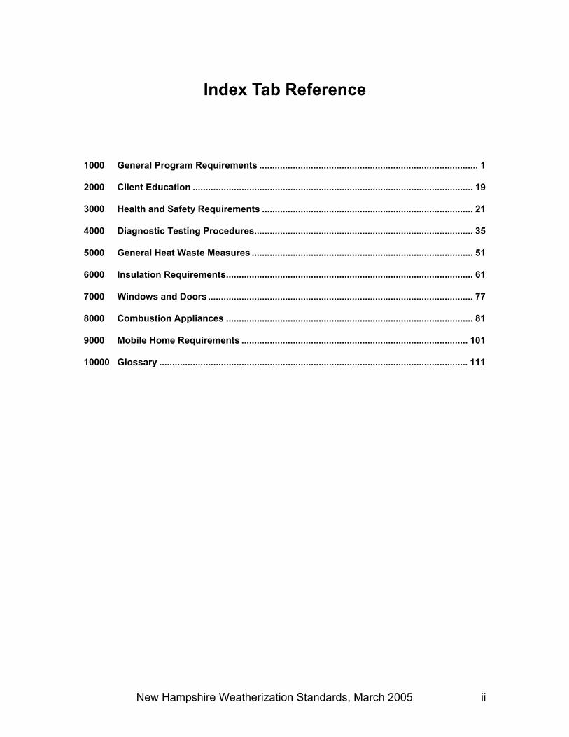
1000 General Program Requirements ..................................................................................... 1
2000 Client Education ............................................................................................................. 19
3000 Health and Safety Requirements .................................................................................. 21
4000 Diagnostic Testing Procedures..................................................................................... 35
5000 General Heat Waste Measures ...................................................................................... 51
6000 Insulation Requirements................................................................................................ 61
7000 Windows and Doors ....................................................................................................... 77
8000 Combustion Appliances ................................................................................................ 81
9000 Mobile Home Requirements ........................................................................................ 101
10000 Glossary ........................................................................................................................ 111

New Hampshire Weatherization Standards, March 2005 iii

New Hampshire Weatherization Standards, March 2005 iv
Table of Contents 1000 General Program Requirements ..................................................................................... 1 1100 Effective Date ................................................................................................................................... 1 1200 Scope ............................................................................................................................................... 1 1300 Enforcement ..................................................................................................................................... 1 1400 Amendments to Program Weatherization Standards........................................................................ 1
1410 Weatherization Standards Waivers.............................................................................................. 2 1420 Deferral of Weatherization ........................................................................................................... 3 1430 Response to Combustion Appliance Problems............................................................................ 3
1431 Emergency Situations, Immediate Follow-up Required.......................................................4 1432 Non-Emergency, One-day Follow-up Required...................................................................4 1433 Non-Emergency, Five-day Follow-up Required...................................................................4
1500 Monitoring by State........................................................................................................................... 5 1510 General Procedure....................................................................................................................... 5 1520 Required Corrective Action .......................................................................................................... 5 1530 Appeals of Inspection Reports ..................................................................................................... 6 1540 High-Risk Status .......................................................................................................................... 6
1600 General Auditing and Weatherization Requirements ........................................................................ 6 1610 Required Client File Documentation ............................................................................................ 8
1611 Work Order Requirements...................................................................................................9 1620 Required Auditing Tools and Equipment.....................................................................................10 1630 Equipment Maintenance .............................................................................................................11 1640 Recommended Weatherization Energy Audit Procedure............................................................11
1700 Energy Audit Requirements.............................................................................................................13 1710 Field Audit ...................................................................................................................................13
1711 Defining the Thermal Boundary.........................................................................................13 1720 NEAT Audit .................................................................................................................................14
1800 Subgrantee Final Inspections ..........................................................................................................15 1810 Allowable repairs.........................................................................................................................16
2000 Client Education ............................................................................................................. 19 2100 Client/Owner Education Recommendations ....................................................................................19
3000 Health and Safety Requirements .................................................................................. 21 3100 Weatherization Worker Health and Safety.......................................................................................21 3200 Health and Safety Procedures.........................................................................................................21
3210 Subgrantee Health and Safety ....................................................................................................21 3211 Subgrantee Deferral of Weatherization Services...............................................................24
3220 Asbestos Inspection Procedures.................................................................................................26 3230 Lead-Safe Weatherization ..........................................................................................................26

New Hampshire Weatherization Standards, March 2005 v
3240 Client Health and Safety .............................................................................................................27 3250 Moisture Remediation, Assessments, and Repairs.....................................................................28
3251 Remediation of Mold .........................................................................................................28 3252 Assessment of Moisture Conditions ..................................................................................28 3253 Mitigation of Moisture Sources ..........................................................................................29 3254 Dryer Vents .......................................................................................................................29
3260 Building Tightness Limit (BTLa) ..................................................................................................30 3270 Ventilation Systems for Acceptable Indoor Air Quality ................................................................30
3271 New Systems, Intermittent Operation................................................................................30 3272 New Systems, Continuous Operation................................................................................30 3273 Existing Exhaust Fans.......................................................................................................31
3300 Carbon Monoxide Alarms ................................................................................................................31 3400 Smoke Alarms .................................................................................................................................33 3500 Blower Door Safety..........................................................................................................................33 3600 Electrical Safety ...............................................................................................................................34
3610 Knob-and-Tube Wiring................................................................................................................34 3620 Junction Boxes............................................................................................................................34 3630 Ground-Fault Circuit Interrupt .....................................................................................................34 3640 Heat Tape ...................................................................................................................................34
4000 Diagnostic Testing Procedures..................................................................................... 35 4100 Blower Door Testing ........................................................................................................................35
4110 Introduction .................................................................................................................................35 4110 Preparation for Blower Door Test................................................................................................35 4120 Blower Door Test, Depressurization (normal) .............................................................................36 4130 Blower Door Test, Pressurization................................................................................................37
4200 BTLa Procedures and Calculation ...................................................................................................38 4210 Introduction .................................................................................................................................38 4220 General Procedure......................................................................................................................38
4300 Depressurization Tightness Limit (DTL)...........................................................................................40 4310 Introduction .................................................................................................................................40 4320 Calculation Procedure.................................................................................................................40
4400 Air Handler Pressure Balance Testing.............................................................................................42 4410 Introduction .................................................................................................................................42 4420 Whole House Test Procedure.....................................................................................................42 4430 Room-to-Room Test Procedure ..................................................................................................43
4500 Worst-Case Draft Testing ................................................................................................................43 4510 Introduction .................................................................................................................................43 4520 Test Procedure ...........................................................................................................................44
4600 Pressure Pan Testing Procedures for Mobile Homes ......................................................................46 4610 Introduction .................................................................................................................................46 4620 Test Procedure ...........................................................................................................................46

New Hampshire Weatherization Standards, March 2005 vi
4700 Zone Pressure Diagnostics (ZPD) Testing ......................................................................................47 4710 Introduction .................................................................................................................................47 4720 Use of Zone Pressure Diagnostics..............................................................................................48 4730 Test Procedures..........................................................................................................................48
5000 General Heat Waste Measures ...................................................................................... 51 5100 Air Sealing Requirements ................................................................................................................51
5110 Blower Door Use.........................................................................................................................51 5120 Air Sealing Guidelines.................................................................................................................51 5130 Room-to-Room Pressures ..........................................................................................................52 5140 Air Sealing Basement Ceilings....................................................................................................53 5150 Zone Pressure Diagnostics.........................................................................................................53 5160 Window Air Conditioners.............................................................................................................54 5170 Fireplace Chimney Plugs, and Equipment Covers......................................................................54
5200 Duct Leakage ..................................................................................................................................54 5210 Introduction .................................................................................................................................54 5220 Duct Leakage Standards ............................................................................................................55
5221 Site-Built Homes, Including Manufactured Housing ..........................................................55 5300 Domestic Water Heaters..................................................................................................................56
5310 Water Heater Blankets................................................................................................................56 5311 Materials............................................................................................................................56 5312 Installation .........................................................................................................................56
5320 Domestic Hot Water Temperature ..............................................................................................56 5330 Domestic Hot Water Pipes..........................................................................................................57 5340 Low-Flow Devices.......................................................................................................................57
5400 Heat Distribution Systems ...............................................................................................................57 5410 Ductwork Inspection, Cleaning, and Sealing...............................................................................57 5420 Ductwork Sealing Materials ........................................................................................................58 5430 Ductwork Insulation.....................................................................................................................59
5500 Piped Distribution Requirements .....................................................................................................60 5510 Steam and Hot Water Heating Distribution Pipes .......................................................................60
6000 Insulation Requirements................................................................................................ 61 6100 Attic Insulation .................................................................................................................................61
6110 Inspection and Repairs ...............................................................................................................61 6111 Moisture Inspection and Repair.........................................................................................61 6112 Electrical Safeguards ........................................................................................................61 6113 Insulation Shielding and Blocking......................................................................................62 6114 Treatment of Other Hazards..............................................................................................63 6115 Attic Access.......................................................................................................................63
6120 Installation Methods for Attic Insulation.......................................................................................63 6121 Insulation Coverage and Density.......................................................................................64 6122 Enclosed Ceiling Cavities ..................................................................................................65

New Hampshire Weatherization Standards, March 2005 vii
6123 Storage Space...................................................................................................................65 6124 Ductwork Insulation ...........................................................................................................65
6130 Attic Ventilation ...........................................................................................................................65 6131 General Installation ...........................................................................................................65 6132 Attic Ventilation Types.......................................................................................................66
6200 Sidewall Insulation ...........................................................................................................................66 6210 Inspection and Repairs ...............................................................................................................66
6211 Interior Inspection and Repairs..........................................................................................66 6212 Exterior Inspection and Repairs ........................................................................................67
6220 Installation Methods for Wall Insulation.......................................................................................67 6221 Blocking.............................................................................................................................69 6222 Insulating Floor Cavities Between Exterior Wall Cavities ..................................................69 6223 Materials............................................................................................................................69 6224 Insulation Coverage, Density, and Voids...........................................................................70 6225 Plugs and Patching ...........................................................................................................70
6300 Foundation Insulation ......................................................................................................................70 6310 Inspection and Repairs ...............................................................................................................70
6311 Moisture Inspection and Repair.........................................................................................71 6312 Wall Moisture Barrier .........................................................................................................71
6320 Installation Methods ....................................................................................................................72 6321 Storage Space...................................................................................................................72 6322 Materials............................................................................................................................72 6323 Insulation Coverage ..........................................................................................................72 6324 Rim Joist Insulation ...........................................................................................................72 6325 Foundation Insulation ........................................................................................................73 6326 Crawl space Insulation ......................................................................................................73
6400 Floor Insulation ................................................................................................................................74 6410 Inspection, Preparation, and Repairs..........................................................................................74
6411 Moisture Inspection and Repairs .......................................................................................74 6412 Treatment of Other Hazards..............................................................................................74
6420 Installation Methods for Floor Insulation .....................................................................................75 6421 Materials............................................................................................................................75 6422 Insulation Coverage ..........................................................................................................75 6423 Ducts and Pipes ................................................................................................................75
6430 Crawl space Ventilation ..............................................................................................................76
7000 Windows and Doors ....................................................................................................... 77 7100 Primary windows..............................................................................................................................77
7110 Window Assessment...................................................................................................................77 7120 Window Replacements ...............................................................................................................77 7130 Window Repairs..........................................................................................................................77
7200 Storm Windows and Insulation Systems..........................................................................................77

New Hampshire Weatherization Standards, March 2005 viii
7210 Storm Windows...........................................................................................................................77 7220 Movable Window Insulation Systems..........................................................................................78
7300 Doors ...............................................................................................................................................78 7310 Door Assessment........................................................................................................................78 7320 Door Air Leakage ........................................................................................................................79 7330 Door Repairs...............................................................................................................................79 7340 Door Replacements ....................................................................................................................79
8000 Combustion Appliances ................................................................................................ 81 8100 Introduction......................................................................................................................................81
8110 Priority.........................................................................................................................................81 8200 Combustion Appliance Work Documentation ..................................................................................81 8300 General Requirements.....................................................................................................................81 8400 Replacement and Installation Procedures .......................................................................................82 8500 Fuel Conversions.............................................................................................................................82 8600 Combustion Efficiency and Analysis ................................................................................................83
8610 Testing Methods .........................................................................................................................83 8700 Combustion Appliance Safety Testing and Repairs.........................................................................86
8710 Combustion Air Supply ...............................................................................................................87 8720 Venting Combustion Appliances .................................................................................................88 8730 Draft, Backdrafting, and Spillage.................................................................................................88 8740 Flexible Gas Connectors.............................................................................................................89 8750 Heat Exchangers ........................................................................................................................89 8760 New Ductwork Installations.........................................................................................................89 8770 Forced Air Systems.....................................................................................................................90
8771 Gravity, Space, Wall, and Floor Furnaces .........................................................................91 8772 Mobile Home Sealed Combustion Furnace .......................................................................92
8780 Boilers.........................................................................................................................................93 8790 Solid-Fuel Heating Systems........................................................................................................94 87100 Gas and Oil-fired Water Heaters.................................................................................................96 87110 All Other Heating Systems..........................................................................................................96
8800 Gas Range Testing..........................................................................................................................96 88120 Gas Range Inspection ................................................................................................................96 88130 Client Education..........................................................................................................................99 88140 Measurement of Emissions from Oven .......................................................................................99
9000 Mobile Home Requirements ........................................................................................ 101 9100 Inspections and Repairs ................................................................................................................101
9110 Moisture Problems ....................................................................................................................101 9120 Electrical Inspections ................................................................................................................101 9130 Combustion Systems ................................................................................................................101
9200 Air Leakage Reduction Requirements ...........................................................................................101

New Hampshire Weatherization Standards, March 2005 ix
9300 Ceiling Insulation ...........................................................................................................................102 9310 Mobile Home Sealed Combustion Furnaces.............................................................................103
9311 Mobile Home Furnace, Combustion Air Through Floor ...................................................104 9400 Ductwork........................................................................................................................................104
9410 Conversion Process..................................................................................................................104 9420 Crossover Ducts .......................................................................................................................105 9430 Duct Sealing Standard ..............................................................................................................106
9500 Floor (Belly) Insulation ...................................................................................................................107 9510 Floor Insulation Requirements ..................................................................................................107 9520 Floor Insulation Methods...........................................................................................................108
9600 Sidewall Insulation .........................................................................................................................109 9610 Sidewall Insulation Requirements .............................................................................................109 9620 Sidewall Insulation Methods .....................................................................................................109
9700 Water Pipe Insulation.....................................................................................................................109 9800 Water Heater Closets and Tanks...................................................................................................110
10000 Glossary ........................................................................................................................ 111

New Hampshire Weatherization Standards, March 2005 x
Introduction The New Hampshire Weatherization Standards provide guidelines to the local administering subgrantees regarding the proper delivery of weatherization and heating system services for residential buildings. The purpose of the Standards is to ensure that high-quality service is given at a reasonable cost and delivered uniformly throughout the State. The success of this program depends upon subgrantees and contractors having a full understanding of the State's Weatherization Standards. The objective of this document is two-fold. First, it serves to define the appropriate application of weatherization measures for each residence serviced. The manual delineates material specifications as well as the steps that should be followed to complete each measure. Alternative methods will continue to be allowed, but whatever method is used must meet or exceed the standard described in the relevant section of this document. Second, these Weatherization Standards set guides for the expectation of quality of the installed product. Procedures are included for evaluating the quality of each installed conservation measure and the overall quality of the completed job. Additionally, it is anticipated that these Standards will help ensure that weatherization program funds are used in the most cost-effective manner possible. The Weatherization Program has changed substantially, both technically and administratively, since its inception almost three decades ago. The weatherization process continues to evolve in response to changes in funding, weatherization technology, program rules, and administrative personnel. The New Hampshire Weatherization Standards will be used to implement and document these changes as they occur. The Weatherization Standards are organized to easily accommodate the future changes. In preparing this edition, some topics may have been overlooked. The manual will become more complete and comprehensive with use as omissions are identified, and new topics are addressed with new policy or guidance.

New Hampshire Weatherization Standards, March 2005 xi

1000 General Program Requirements 1400 Amendments to Program Weatherization Standards
New Hampshire Weatherization Standards, March 2005 1
1000 General Program Requirements
1100 Effective Date All weatherization measures performed or completed by the subgrantees on or after the date specified in the cover letter to these Standards shall comply with these Standards.
1200 Scope 1. The Goal for the New Hampshire Office of Energy and Planning
(OEP) Weatherization (Wx) Program is: "To reduce heating and cooling costs for low-income families, particularly for the elderly, people with disabilities, and children, by improving the energy efficiency of their homes and ensuring their health and safety."
2. The New Hampshire Weatherization Standards are referred to throughout this document as "the Standards."
3. The Standards shall apply to all local administering agencies (subgrantees) providing weatherization program services.
4. The Standards provide minimum guidelines for the installations of energy conservation measures and repairs. Materials and measures that are allowed or not allowed will be specifically designated.
5. These Standards are not intended to abridge safety, health, environmental, local codes, or other ordinances. Such requirements, if more stringent than these, shall apply; if these Standards are more stringent, the Standards shall apply.
6. All questions concerning the content or implementation of the Weatherization Standards should be directed to the OEP Wx Program Manager.
1300 Enforcement 1. Continued subgrantee inability or refusal to comply with applicable
standards are grounds for the New Hampshire OEP to suspend, terminate, or otherwise apply special condition(s) to the subgrantee’s agreement to provide weatherization services.
1400 Amendments to Program Weatherization Standards 1. From time to time, the New Hampshire Weatherization Standards may
be amended and/or revised by the OEP to reflect changes in State and Federal regulations, state-of-the-art technology, and general experience of the weatherization community.

1000 General Program Requirements 1400 Amendments to Program Weatherization Standards
New Hampshire Weatherization Standards, March 2005 2
2. Amendments to the Standards will not become effective until thirty (30) calendar days from the date of OEP approval and subgrantee notification except under the following conditions, when amendments or revisions will become effective immediately: a. State or Federal law or regulation changes mandate immediate
implementation; or b. The OEP determines that an emergency situation exists, such as
a potential threat to life, limb, or personal property, and the proposed amendment and/or revision is necessary for the protection of the health and welfare of New Hampshire citizens or weatherization personnel.
3. Any subgrantee personnel may submit comments and suggested changes or revisions to these Standards to the Office of Energy and Planning at any time. Suggested changes to the Standards must be accompanied by supporting documentation.
1410 Weatherization Standards Waivers 1. Deviations from the Weatherization Standards require a waiver from
the OEP Weatherization Program Manager prior to the expenditure of funds. Work may proceed after verbal authorization by the OEP Weatherization Program Manager. An electronic or hard copy documenting authorization will be forwarded and kept on file.
2. Waivers may be granted: a. If a client/occupant refuses to allow a certain measure to be
completed and this measure has a higher savings-to-investment ratio (SIR) than the remaining measures. In this case, no other measures may be installed, with the exception of general heat waste and health and safety measures. Subgrantees should explain the potential energy savings to the client to ensure that they understand the ramifications of their decision. Subgrantees must document the reason the work was not performed.
b. To convert water heaters or heating systems to a different fuel type.
i. Gas water heaters may be replaced with electric water heaters if it is necessary to address an unsafe venting situation.
ii. Clients have the option of declining or waiving a conversion for personal reasons. For example, if a conversion requires that a new venting system be run through finished space and the client does not like the appearance, the client may decline the conversion.
iii. Agencies must first educate the client regarding the advantages and disadvantages of switching fuels. If the client declines the conversion, they must sign a statement in the client file waiving the conversion.

1000 General Program Requirements 1400 Amendments to Program Weatherization Standards
New Hampshire Weatherization Standards, March 2005 3
iv. Fuel-switching costs should be analyzed for cost effectiveness using the approved audit.
v. Fuel conversions must be completed by qualified personnel in compliance with applicable building codes.
1420 Deferral of Weatherization 1. Conservation measures and associated repairs may be omitted if the
work cannot be completed because of health, safety, local codes, or other technical reasons. The following are examples of acceptable grounds for a waiver: a. Risk to client or subgrantee staff due to health or safety risks such
as fire, explosion, bodily harm, unruly pets, harmful combustion by-products, electric shock, friable asbestos, severe unsanitary conditions, severe structural damage, or height clearance.
b. Deferrals do not require State approval, but a brief explanation must be documented in the client file. For further details on the Deferral of Weatherization policy, please refer to Subgrantee Deferral of Weatherization Services on page 24.
1430 Response to Combustion Appliance Problems 1. It is often best to contact the local gas company or oil dealer to correct
problems with a client's combustion appliance or heating unit. Gas utilities usually have their own emergency response protocols; these should be respected. The items listed below are not intended to interfere with gas utilities emergency protocols (often called tagging procedures). In each of the situations in Sections 1431 through 1433, the appliance technician will evaluate the client’s situation, in consultation with the subgrantee Weatherization Director, for the purpose of determining if: a. The client can safely remain in the home with an alternative
source of heat. Clients without heat during the heating season shall be provided with temporary heating appliances (portable electric space heaters) to ensure thermal comfort, stabilize the situation, and prevent damage to the dwelling.
b. If the technician believes the client cannot safely remain in the home, they will be advised to make arrangements to stay with family or friends until the unit can be occupied again.
2. Documentation supporting the needed repairs must be kept in the client file. Repairs done under the Weatherization Program must be included as part of the SIR calculation computed by the NEAT computerized audit, unless the work was done to protect the client's health and/or safety.

1000 General Program Requirements 1400 Amendments to Program Weatherization Standards
New Hampshire Weatherization Standards, March 2005 4
1431 Emergency Situations, Immediate Follow-up Required Some safety problems may warrant discontinuing the combustion appliance testing or shutting off the appliance until the repairs can be made. When this situation occurs with a space heating appliance, the client must be left with an alternative source of heat. Whenever a technician questions the safety of a situation, they should consult a supervisor. Examples of this type of situation are:
1. Propane or natural gas leak: Propane can be smelled more than three feet from the leaking fitting.
2. Clogged or disconnected flue: A clogged or disconnected flue that cannot be fixed, causing significant spillage of combustion products into a heated space or working area of the technician.
3. Backdrafting or significant spillage: Any backdrafting of combustion products in combination with carbon monoxide indications, which cannot be fixed.
4. Cracked furnace heat exchanger: Any visually identified cracked heat exchanger leaking combustion byproducts.
5. Other hazards: Any other situation or combination of situations that the technician or supervisor judges hazardous to the health of the client or others.
1432 Non-Emergency, One-day Follow-up Required Some situations may not warrant discontinuing testing or shutting down the heating system, but are serious enough to require attention within twenty-four hours. Examples of this type of situation are:
1. If carbon monoxide measured in the heated space exceeds the levels listed in Table 8-4 in the Combustion Appliances Section on page 86.
2. There is inadequate draft, i.e., spillage. 3. A furnace with no limit switch, or a limit switch that is disconnected.
1433 Non-Emergency, Five-day Follow-up Required All other safety-related follow-up must begin within five days. Examples of this type of situation are:
1. Unacceptable draft (with spillage) in an unheated area. 2. A furnace limit switch that does not shut the gas off by 225o F. 3. A cracked heat exchanger is suspected, but there are no other
apparent problems with the furnace.

1000 General Program Requirements 1500 Monitoring by State
New Hampshire Weatherization Standards, March 2005 5
1500 Monitoring by State
1510 General Procedure 1. Periodically, the OEP Wx Manager or their representative will conduct
subgrantee monitoring visits for the purpose of determining that all materials and services reported have been installed or completed according to the Standards.
2. The effectiveness, safety, workmanship, overall appearance, and compliance with the Standards will be evaluated during the monitoring visit.
3. Dwelling units inspected may be selected by the Wx Program Manager from a list of clients that will allow a representative sample.
4. Inspection visits may focus on problem areas identified in previous inspection reports to ensure that problems have been corrected.
5. Recommended Actions and/or Required Corrective Actions may be issued to the subgrantee based on observations during these visits, and such guidance will be noted on a report provided to the subgrantee.
6. If a weatherization measure or repair is not in compliance with the Standards and a waiver has not been issued, the expenditures for that measure might not be allowed.
7. Deficiencies noted during State monitoring that result in Required Corrective Actions may be considered as justification for requiring that the subgrantee re-inspect other dwellings. Please refer to Section 1520 below for the details of Required Corrective Actions.
8. A written response to Required Corrective Actions shall be submitted to OEP within 30 days detailing the completion of the corrective action.
1520 Required Corrective Action 1. Any of the following circumstances generally result in a Required
Corrective Action being issued: a. The health and safety of clients, subgrantee staff or
subcontractors, or the integrity of the building structure is threatened by work completed with weatherization funds.
b. A health or safety problem is created by, exacerbated by, or not corrected by the delivery of weatherization services.
c. The omission of a required measure or technique with major energy savings potential, as determined by NEAT, or the omission of a required procedure that addresses health and safety concerns.
d. Poor quality of work that significantly affects the performance of measures or repairs.

1000 General Program Requirements 1600 General Auditing and Weatherization Requirements
New Hampshire Weatherization Standards, March 2005 6
e. Expenditure of weatherization funds on measures that are not approved under the weatherization Standards or not required for health or safety reasons.
f. Major expenditure of funds on measures that do not yield an acceptable savings-to-investment ratio as defined in these Standards.
g. Any action or lack of action that may result in a liability that threatens OEP financial assistance award funds.
2. A Monitoring Report that contains Required Corrective Action may result in: a. Disallowed costs. b. An increased inspection/monitoring rate. c. The requirement of additional training for the subgrantee
personnel. d. Recommendation for High Risk Status for the subgrantee (please
refer to Section 1540). 3. Continued findings of this type may result in termination of OEP
Weatherization Financial Assistance Award to the subgrantee.
1530 Appeals of Inspection Reports 1. A subgrantee representative may appeal the findings of the monitoring
inspection report to the Wx Program Manager. This appeal should be sent in writing within thirty working days of receipt of the inspection report.
2. A subgrantee who does not agree with the initial outcome of the inspection report appeal may submit a subsequent appeal to the Director of the Office of Energy and Planning.
1540 High-Risk Status 1. The occurrence of a substantial number of, or repeated, Required
Corrective Actions may result in a decision by the Wx Program Manager to give a subgrantee high-risk status. Please see Section 1520 above, for an explanation of Required Corrective Actions.
2. If a subgrantee is placed on high-risk status, special conditions will likely be placed upon the subgrantee's financial assistance award until the subgrantee complies with the Weatherization Standards.
1600 General Auditing and Weatherization Requirements 1. The correct use of the NEAT energy audit and its associated priority
list is required. At least annually, each subgrantee must update all applicable information used by the computerized audit (i.e., costs for measures, cost of materials, labor costs, and fuel types). The subgrantee must also document their method for insuring the accuracy of the input data.

1000 General Program Requirements 1600 General Auditing and Weatherization Requirements
New Hampshire Weatherization Standards, March 2005 7
a. Costs shall include fringe benefits as defined by the subgrantees accounting system.
b. Insulation cost estimates must be based on at least the manufacturers recommended minimum installation density.
2. The health and safety of the clients, subgrantee staff, subcontractors, and the integrity of the building structure must not be compromised by any work completed with weatherization funds.
3. The subgrantee weatherization director has overall responsibility for the proper implementation of the procedures detailed in the Weatherization Standards.
4. All weatherization installations, both repairs and conservation measures, must comply with applicable building codes and regulations.
5. Subgrantees are responsible for the quality of all repair and energy conservation work.
6. If an eligible client moves during the course of the weatherization work, the subgrantee should complete the repair and/or conservation work in progress and any health and safety measures necessary to secure the well being of future occupants. However, additional conservation or repair work should not be started.
7. Weatherization is not to proceed until problems beyond the scope of the program affecting either the integrity of installed weatherization measures or the health and safety of the client or crew/contractor are remedied with non-weatherization funds.
8. Health- and safety-related repairs within the scope of weatherization services include the following: a. Heating system replacements. b. Materials to reduce excessive carbon monoxide to below-action
level. c. Heat exchanger replacements or repairs. d. Burner replacements or repairs. e. Combustion air venting system repairs or replacements. f. Repair of gas leaks, including necessary materials. g. Chimney cleaning and lining. h. Water heater tank replacements.
9. The costs for health and safety repairs are not to be factored into cost-effectiveness analyses (the Savings-to-investment ratio) if they are below the $500 maximum allowed cost.
10. Allowable repairs which can be completed within the limits of weatherization funding must be associated with an eligible weatherization measure such as the following: a. Mechanical ventilation system materials. b. Electrical repair materials. c. Plumbing repair materials.

1000 General Program Requirements 1600 General Auditing and Weatherization Requirements
New Hampshire Weatherization Standards, March 2005 8
d. Structural repairs (include roofing, siding, ceiling, floor, foundation, and mobile home belly repairs) that are necessary for the installation of energy conservation measures.
e. Vapor barrier installation. f. Drainage repairs or modifications. g. Clothes dryer venting.
11. When repairs cost more than $500, are not associated with a weatherization measure, or cannot be justified with a savings-to-investment ratio (SIR) greater than 1.00, the client and homeowner must be notified and referred to alternative resources (home rehabilitation programs, landlords, etc). This occurrence must be documented in the client file.
12. Subgrantees must guarantee work done under the Weatherization Program for a period of one year after completion. A job is considered completed upon successful final inspection.
1610 Required Client File Documentation Documentation for each completed client file must contain:
1. Documentation of the initial audit, including the auditor's name and the date of the initial audit.
2. The final inspection forms, signed and dated by the client and a certified energy auditor, attesting that the work is complete and satisfactory. The inspection shall be performed by the auditor and, when practical, should be performed on the date the work is completed.
3. A copy of an accurate NEAT audit priority list that was used for the job or report from the NEAT audit.
4. Accurate records or documentation of all installed measures and their costs. Costs must include the labor used to install the measure.
5. Each client file must include documentation of all efficiency work and adjustments made to the water heating and space heating combustion appliances, when applicable. Documentation in the client file must include: a. Information on the applicable combustion appliance efficiency
tests (see Section 8600, Combustion Efficiency and Analysis on page 83) and components (see Section 8700 on page 86).
b. Copies of the letter of condemnation and the permit to install and operate shall be included in the client file.
c. Documentation of all safety tests and work done on combustion appliances.
6. Pre- and post-weatherization blower door test information and the BTLa value in units of CFM50.
7. A complete record of the pressure diagnostics tests performed. 8. Waivers and explanations:
a. Approved waivers, when applicable.

1000 General Program Requirements 1600 General Auditing and Weatherization Requirements
New Hampshire Weatherization Standards, March 2005 9
b. An explanation of reasons that any dwelling unit did not have a blower door test performed.
c. An explanation for reasons that any weatherization measures with a SIR greater than 1.25 were not installed.
d. A list of any conditions that are judged to be out of the ordinary (e.g., non-operable egress doors and windows).
e. Air leakage measures that are done to address client comfort (e.g., installing a storm window near a reading chair, installing a jamb-up kit on a door near a reading chair, etc.).
9. Client Information: a. A signed FAP/Wx application. b. A completed unit priority scorecard. c. Brief documentation indicating that owners and clients were
notified of any potential or real health or safety problems that necessitated weatherization work be deferred.
d. A copy of an executed landlord/tenant agreement if the weatherized dwelling is rental property.
e. A completed Consent and Agreement form. f. The signature of the dwelling unit owner must be contained in the
file when the owner agrees to permanently seal an unused fireplace.
g. The pamphlet, "Protect Your Family from Lead" must be distributed when all three of the following conditions exist:
i. The dwelling was constructed prior to January 1, 1978, and ii. The dwelling has not been determined to be free of lead-
based paint, and iii. Either the amount of disturbed lead-based painted surface
exceeds 2 square feet per room of interior surface, 20 square feet of exterior surface, or 10 percent of a small component type (e.g., window); or the amount of lead-based paint dust that will be generated by the Weatherization work exceeds the OSHA-defined airborne levels for lead.
h. A client-signed copy of the client education checklist.
1611 Work Order Requirements 1. Each client file must have an accurate work order generated by the
energy auditor responsible for the job. 2. An acceptable work order is one for which all installed energy-saving
weatherization measures have a Savings-to-investment ratio (SIR) of 1.00 or greater. a. Measures for which SIR values are less than 1.00 are ineligible. b. All energy-saving measures must be considered and ranked in
order of descending SIR. Installing a measure with a lower SIR without installing others with greater SIR is forbidden; in other words, measures may not be skipped.

1000 General Program Requirements 1600 General Auditing and Weatherization Requirements
New Hampshire Weatherization Standards, March 2005 10
c. If, because of a budget constraint or other valid reason, all measures having an SIR of one or greater are not installed, a written explanation must be included in the client file.
d. It is not permissible to omit measures vital to the success of the weatherization job. For example, it shall is not be permissible to partially insulate a dwelling because of budget constraints.
3. If the auditor is aware of more than one method of installing an energy conserving measure, he must be able to justify, in writing in the client file, the selection of a method that does not have the highest SIR of the possible methods.
4. The work order must clearly itemize the work to be completed by the agency crew or contractor. The work order must: a. Be well organized and legible. b. Include all appropriate dimensions and quantities. c. Include any appropriate special instructions for necessary
inspections or unusual installations. d. The method of insulation installation with the proposed amount,
type, and R-Value of the insulation to be installed. e. The type of vapor barrier and ventilation to be installed, if any. f. The name, the principals, and business mailing address of the
firm providing and installing the insulation. g. Details of any warranties on materials used in the home. h. A description of the guarantee on settling, including anticipated
amount and time frame of settling. i. A written description of any work required for the installation of the
insulation, including who will do the work and who will pay for it. j. A written description of any work required for the installation of the
insulation, including who will do the work and who will pay for it.
1620 Required Auditing Tools and Equipment 1. Minneapolis Blower Door, Model 3. 2. Digital or magnahelic manometer. 3. Bacharach Monoxer II or other carbon monoxide detector. 4. Combustion analyzer (Lynn or Bacharach wet kit or electronic Fyrite,
Fyrite Pro). 5. Leakator or other combustible gas detector. 6. Suretest circuit analyzer. 7. Electric current tester. 8. TI-86 calculator with ZipTest Pro2™ building diagnostic software. 9. NEAT software installed on a computer with current cost data.
10. Digital camera. 11. Flashlight and mirror. 12. OSHA-approved respirator. 13. Toolbox with miscellaneous tools. 14. Stepladder. 15. Extension cord.

1000 General Program Requirements 1600 General Auditing and Weatherization Requirements
New Hampshire Weatherization Standards, March 2005 11
1630 Equipment Maintenance 1. All test equipment used for diagnostics, evaluation, and installation of
measures shall be maintained according to the manufacturer’s recommendations. This includes: a. Calibration of electronic equipment, including, but not limited to:
i. Instruments for measuring carbon monoxide. ii. Instruments for measuring combustion efficiency. iii. Equipment for measuring electrical consumption. iv. Digital manometers.
b. Recommended maintenance of mechanical equipment and electric motors, including, but not limited to:
i. Blower door fans. ii. Analog manometers. iii. Insulation blowing machines including their motors, hoses,
seals, and filters. 2. Agencies should develop and adhere to an equipment maintenance
schedule for equipment used by energy auditors. 3. Contractors should develop and adhere to an equipment maintenance
schedule for equipment used for weatherization program work.
1640 Recommended Weatherization Energy Audit Procedure
Invariably, every auditor will develop their own style of conducting a weatherization audit. The following steps, however, outline a basic approach that an auditor may use as a guide to effectively assess a housing unit for weatherization.
1. During the telephone conversation to schedule the audit, be sure to ask the client not to operate their fireplace or woodstove the day of the audit (if possible) so that you can safely conduct the blower door test.
2. Get paper work and equipment ready at your vehicle while making initial observations of the house. It may be best to organize yourself ahead of time as household members may be concerned by someone sitting in a vehicle in their driveway for an extended period of time.
3. Introduce yourself to the client, explain why you are there, and give the client a business card.
4. Briefly discuss what the audit will involve. Explain that you will need to be "poking around" throughout the house – closets, attic, basement, etc. Get permission to walk through the house and ask if the client will want to accompany you during the audit.
5. Have the client sign the "Consent to Perform Audit" section on the Consent and Agreement Form.
6. If there is a basement, start there. If there are any major health or safety problems the heating system, this is a likely place to find them. Make a visual assessment of the heating unit – the type, make, venting, condition, fuel type, and safety switches.

1000 General Program Requirements 1600 General Auditing and Weatherization Requirements
New Hampshire Weatherization Standards, March 2005 12
7. Depending on the season, decide when to conduct the heating system efficiency test. In summer, do this first and then operate the blower door to cool down the house. In winter, do the reverse. Be sure to check all health and safety devices and test the CO level of all combustion equipment.
8. Inspect the rest of the house – bathrooms, attic, kitchen, bedrooms, closets, and crawl spaces. Be observant throughout this process. Look for obvious air leaks as well as health and safety issues. Check the ground fault circuit interruption (GFCI) outlets, venting equipment, look for moisture problems, etc.
9. Check the insulation levels in attic, walls, and crawl spaces. 10. Conduct a blower door test if it is appropriate, i.e., if there are no
major indoor air quality problems, no friable asbestos (refer to Section 3500 on page 33), and the wood stove is not burning. Check that combustion equipment is turned off and the house is in winter condition. Zero the gauges and conduct the blower door test.
11. Walk around the house with the blower door running and check for air leakage. Do not forget to check for leaks in conditioned basements.
12. Perform other appropriate tests, such as zone pressure diagnostics. 13. Measure the perimeter of the house from the inside or outside. If it is a
complicated house, you may want to do this at the beginning of your audit and make your sketch of the floor plan so that you are oriented when inspecting the interior of the house.
14. Use the digital camera to photograph the heating system and any areas of the house that may present a challenge. These can be a valuable reference when you're back in the office writing up the job.
15. Put personal and household items back where you found them. Relight any pilot lights that may have been extinguished during the blower door test.
16. Perform an exit interview with the client. Explain what you have found and what measures might be installed. Let them know when you will be back, or when you or the contractor will contact them. Leave a business card so that they can contact you if they have any questions. Have the client sign the "Consent to Perform Work" section on the Consent and Agreement Form.
17. Look over your paperwork for a few minutes in the car before you drive away to be sure you have collected all the information you need. Organize your notes. Be sure you have done everything you need to on-site.
18. Run the data through the ZipTest Pro2™ and NEAT software, as necessary, and decide which measures will be cost-effective.
19. Write up a work order of the most cost-effective measures for the home. Write or type the job order legibly and describe the work requests clearly and specifically. Follow agency-specific procedures for competitive bidding and assigning contractors.

1000 General Program Requirements 1700 Energy Audit Requirements
New Hampshire Weatherization Standards, March 2005 13
20. When practical, visit the contractor on-site the day the work is scheduled. This helps you both to better learn the weatherization process.
21. Perform a final inspection of the work upon receipt of the bill from the contractor. Have the client sign the "Satisfaction" section of the Consent and Agreement Form.
1700 Energy Audit Requirements
1710 Field Audit 1. A field audit of each unit must be conducted and documented in the
unit file. 2. The field audit must include:
a. A health, safety, and hazards assessment of the unit as well as the combustion appliances;
b. A cost-effective analysis using the approved energy audit system; c. An air leakage/ventilation assessment; d. A moisture assessment; e. A ductwork assessment; f. An insulation assessment; and g. A general heat waste assessment.
3. The installation of weatherization materials without appropriate justification by the NEAT audit is not allowed.
4. The thermal boundary of each dwelling must be determined during the field audit. This includes the identification of each part of the thermal shell or envelope.
5. All building cavities that define the thermal boundary between the conditioned and unconditioned space must be inspected and measured for existing insulation R-values, structural integrity, and the need for repairs.
6. The field audit must identify the most appropriate methods for: a. Reducing air leakage and convective bypasses, and b. Increasing the insulating value of thermal boundary surfaces,
when appropriate.
1711 Defining the Thermal Boundary 1. If a basement or crawl space houses a heating system and other
appliance, it should be treated as a conditioned area. In this case, the basement or crawl space walls are part of the boundary of the conditioned envelope. The preferred strategy is to air seal and insulate the basement or crawl space walls because this encloses the furnace, ducts, pipes, water heater, and other appliances within the conditioned envelope. Attics will almost always be defined as outside of the thermal boundary, as will garages and porches.

1000 General Program Requirements 1700 Energy Audit Requirements
New Hampshire Weatherization Standards, March 2005 14
2. If the appropriate thermal boundary is determined to be a basement or crawl space wall rather than the floor above the basement/crawl space, then the basement or crawl space wall should be sealed, as necessary, before any insulation is installed on these surfaces.
a. In most cases, air sealing and insulation should only be done between a conditioned and unconditioned space.
1720 NEAT Audit A NEAT audit must be completed on single-family homes. A MHEA should be completed for mobile homes when the software becomes available. Refer to Section 9000 for further details. Agencies must work in consultation with the OEP Weatherization Manager in the development of appropriate priority lists for high rise units three stories or greater, units with large central heating systems, or units with large common areas.
1. A work order must be generated for all weatherization measures having a savings-to-investment ratio (SIR) of 1.0 or greater. a. Measures for which SIR values are less than 1.0 are ineligible. b. Measures for which SIR values are 1.0 to 1.3 are optional. c. Measures for which SIR values are greater than 1.3 are
mandatory. 2. If the energy auditor is aware of more than one method of installing an
energy conserving measure, he must be able to justify, in writing in the client file, the selection of a method that does not have the highest SIR.
3. If repairs must be done in order to protect the integrity of an eligible measure, the repair costs must be included with that measure's cost when the associated SIR is calculated. See Section 1810 on page 16 for details.
4. Values and methods used for the NEAT audit will be periodically updated by either the subgrantee or statewide weatherization committees as follows: a. Costs shall include fringe benefits as defined by the subgrantees
accounting system. b. Insulation cost estimates must be based on at least the
manufacturers recommended minimum installation density. c. Cost estimations used for the approved audit must be updated at
least once each year and procedures used to derive these estimated costs must be documented by the subgrantee.
d. A technical committee, made up of representatives from all the State subgrantees, will update the following each year:
i. The typical service life of each energy-saving measure. The service life values must be discounted for use in the calculation of SIR in accordance with Department of Energy guidelines.
ii. A consistent method determining the cost of fuels to be used in the NEAT audit.

1000 General Program Requirements 1800 Subgrantee Final Inspections
New Hampshire Weatherization Standards, March 2005 15
iii. Maximum insulation levels. Table 1-1
Life of Measures to be used by New Hampshire’s Weatherization Program
Measure Life of Measure Cellulose insulation 20 Yrs Fiberglass batt insulation 20 Yrs Fiberglass blow-in insulation 20 Yrs Foundation panel insulation 20 Yrs ThermoSkirt insulation 15 Yrs InsulPink or interior Dow insulation 20 Yrs Steel doors 15 Yrs Mobile home doors 10 Yrs Heating system 20 Yrs Rim joist insulation 20 Yrs Mobile home windows 15 Yrs Primary window units 20 Yrs Storm windows 15 Yrs Lighting measures 5 Yrs General Heat Waste or Health & Safety N/A (SIR not required)
1800 Subgrantee Final Inspections 1. All weatherized units shall be reported to the Office of Energy and
Planning as complete only after the subgrantee has performed a final inspection. The purpose of the final inspection is to ensure that the work has been completed in a workmanlike manner and in accordance with the NEAT energy audit and work order.
2. The final inspection must document the materials installed and confirm that they were installed in a professional manner in accordance with the New Hampshire Weatherization Standards. The Consent and Agreement form must be signed and dated by both the client and a certified energy auditor.
3. Subgrantees are required to inspect one-hundred percent of installed measures.
4. Deficiencies noted during State monitoring that result in Required Corrective Actions may be considered as justification for requiring that the subgrantee re-inspect dwellings.
5. Client or scheduling obstructions to final inspection: a. OEP recognizes that in some cases it may be impossible to
complete a final inspection of the dwelling unit, even after

1000 General Program Requirements 1800 Subgrantee Final Inspections
New Hampshire Weatherization Standards, March 2005 16
repeated efforts to schedule the inspection. In these cases, the subgrantee must document that an energy auditor made a significant effort to inspect the dwelling after completion of the weatherization work. At a minimum, a visual inspection of any exterior weatherization measures must be completed.
b. A memorandum must be put in the client file, signed by the energy auditor and the agency weatherization director, indicating the dates when the subgrantee attempted to inspect the residence.
i. The subgrantee will also be required to mail a Consent and Agreement to the client for their signature, along with a letter explaining that the subgrantee was unable to complete a full on-site inspection.
ii. If the client does not respond within two weeks, the subgrantee may report the unit as a completion. In this situation, a second memorandum, signed by the energy auditor and weatherization director and placed in the client file, should indicate that the client failed to return the Consent and Agreement form.
6. The final inspection of a unit, at a minimum, shall include: a. Verification that all materials reported on the final inspection sheet
are present or can be physically accounted for on the materials returned sheet during the on-site inspection by the energy auditor.
b. Materials were installed in such a way as to be safe, effective, and neat in appearance.
c. All materials used on the home meet required New Hampshire Weatherization Standards.
d. Verification that all combustion systems are in safe operating condition.
7. The appropriate documentation must be in the client file. Please refer to Section 1610 on page 8 for the file document requirements.
1810 Allowable repairs 1. The costs of incidental or necessary repairs are allowable if they
protect the integrity of the installed weatherization materials. 2. The costs for necessary repairs must be factored into the appropriate
SIR calculation in the approved energy audit (NEAT). Use the suggested allocation formulas listed below for distribution of costs among installed weatherization measures:
a. For electrical inspections and repairs, allocate one-half of the cost to the attic insulation, and one-half the cost to the sidewall insulation.
b. For plumbing repairs: i. For site-built dwellings, allocate one-half the cost to the
floor/perimeter measures, and one-half to the sidewall insulation.

1000 General Program Requirements 1800 Subgrantee Final Inspections
New Hampshire Weatherization Standards, March 2005 17
ii. For mobile homes, allocate one-half the cost to belly insulation, and one-half the cost to air leakage measures.
c. For roofing repairs, allocate one-third the cost to the attic insulation, one-third to wall insulation, and one-third to the air leakage measures.
d. For ceiling repairs, allocate one-half the cost to the attic insulation, and one-half to air leakage measures.
e. For siding repairs, allocate one-half the cost to wall insulation, and one-half to air leakage measures.
f. For mobile home belly repairs, allocate one-half to belly insulation, and one-half to air leakage measures.
3. If repair costs, when factored together with the cost of eligible measures, result in a SIR of less than 1.00, neither the measures nor the repairs may be done entirely with weatherization funds. A subgrantee may use another source of funds to "buy down" the cost of repairs, or the subgrantee may request that the client contribute funds to make the measure and the associated repairs eligible.
4. Costs for the repair or replacement of existing mechanical ventilation or for the installation of new exhaust fans or systems shall be included under health and safety; therefore, it should not be factored into the calculation of an SIR.

1000 General Program Requirements 1800 Subgrantee Final Inspections
New Hampshire Weatherization Standards, March 2005 18
2000 Client Education 2100 Client/Owner Education Recommendations
New Hampshire Weatherization Standards, March 2005 19
2000 Client Education
2100 Client/Owner Education Recommendations 1. Client education should be provided during all phases of the
weatherization process. This includes, but is not limited to: a. The client intake and scheduling. Explain:
i. What the client should expect. ii. How the weatherization process will proceed. iii. Who will call next.
b. The initial field audit. Discuss: i. What the client should expect during the energy audit. ii. Air leaks discovered with the blower door. iii. Any health and safety issues, such as:
1. Lead paint. 2. Asbestos. 3. Combustion venting. 4. Carbon monoxide. 5. Mold and mildew. 6. Plumbing leaks. 7. Animal hazards such as rodent feces or insect
infestations. 8. Electrical hazards. 9. Other possible hazards.
iv. Health and safety issues should be addressed both verbally and by distributing educational pamphlets during the audit "walk-through." This can be particularly effective as the auditor notices and discusses potential hazards.
v. Energy conserving measures that will be installed, such as: 1. Air sealing. 2. Additional insulation. 3. Heating system improvements. 4. Water heater improvements. 5. Baseload reduction measures.
vi. Improvements in the thermal comfort of the dwelling as a result of the weatherization.
vii. An explanation of gas range safety and proper use. Refer to Section 8800 on page 96.
viii. An explanation of required maintenance for existing equipment, added equipment, or energy-saving measures.
ix. What will take place after the energy audit: 1. Schedule of events. 2. Who will contact the client next. 3. When the work will be complete.
x. Work the client must do to prepare for the weatherization:

2000 Client Education 2100 Client/Owner Education Recommendations
New Hampshire Weatherization Standards, March 2005 20
1. Moving stored items to make room for the weatherization work.
2. Any other actions that must take place before the weatherization work begins.
c. The installation and repair of conservation measures. i. Those installing weatherization measures should always
take advantage of client education opportunities, if feasible. Such opportunities may include explaining how and why a measure is being installed and how the measure may reduce the client’s energy bill and improve their comfort.
d. The final job inspection. i. The inspection personnel should reinforce the advantages of
the energy-saving measures installed. ii. The client should always be asked if they have any
remaining questions regarding the weatherization or health and safety work that was done.
iii. The inspection personnel should explain to the client how the dwelling will perform differently as a result of the installed weatherization measures.
e. Whenever possible, demonstrate to educate. Get the client involved in the educational process, if possible. The use of up-to-date written materials is encouraged, but demonstration has proven to work better in most cases.
f. The auditor must obtain a client-signed copy of the client education checklist.

3000 Health and Safety Requirements 3200 Health and Safety Procedures
New Hampshire Weatherization Standards, March 2005 21
3000 Health and Safety Requirements
3100 Weatherization Worker Health and Safety 1. It is the responsibility of the subgrantee to initiate and maintain
programs that provide compliance with applicable Occupational Health and Safety Act Regulations (29 CFR 1910 & 1926), and any other applicable Federal and State laws enacted to protect worker safety.
2. The subgrantee must assess structural conditions and demonstrate caution when working in potentially dangerous areas.
3. Weatherization services must be provided in a manner that minimizes risk to workers.
4. Subgrantee employees shall take precautions to avoid contact with raw sewage or other unsanitary conditions.
3200 Health and Safety Procedures The following section establishes areas of concern that may affect the health and safety of the workers and the clients. In most cases, the best approach to limiting the health and safety risk is to minimize their exposure to the hazard. The inability to minimize exposure may result in some or all of the work being stopped on any particular dwelling. OEP crew/contractors and auditors are not expected to work under conditions that jeopardize their health and safety. It is also expected that these field personnel will use caution and care while working on the client's home. The office, warehouse, and other workspace owned or rented by each subgrantee should be a safe and healthy environment. For detailed information on worker health and safety, refer to Construction Industry OSHA Safety and Health Standards (29 CFR 1926/1910). OEP will allow waivers for non-performance of audits, installations, and/or inspections, or any portion of these functions, if such action will expose workers to conditions regarded as unsafe or unhealthy as determined by OSHA Construction Industry Standards. See Section 3211 on page 24 for more information about audit waivers for health and safety reasons. Expenditure of weatherization funds for materials, protective clothing, respirators, proper tools and equipment, and other items or activities related to the health and safety of clients and workers are allowable health and safety costs under the New Hampshire Weatherization Program.
3210 Subgrantee Health and Safety 1. When in doubt, subgrantees should seek consultation services from
an OSHA subsidized professional safety consultant (See: OSHA

3000 Health and Safety Requirements 3200 Health and Safety Procedures
New Hampshire Weatherization Standards, March 2005 22
Publication # 3047, Consultation Service for the Employer) for identifying hazards and developing a worker health and safety program.
2. Subgrantees must have a Subgrantee Health and Safety Policy in place to protect worker health and safety.
3. The Health and Safety Policy should specify: a. That Material Safety Data Sheets (MSDS) must be on the job site
and available to medical personnel. b. That employees should know where to go for treatment. c. A written procedure for reporting medical emergencies. d. A written procedure for reporting non-emergency accidents. e. How to provide prompt medical attention for serious injuries. f. How to provide prompt transportation or contact an ambulance in
the case of a serious emergency. g. That telephone numbers of physicians, hospitals, or ambulances
should be conspicuously posted. h. That a first aid program should be in place. It should include the
following: i. First aid training provided to at least one member of each
crew/contractor. ii. CPR training provided to at least one member of each
crew/contractor. iii. One complete first aid kit per vehicle. iv. One eye-wash station with at least one refill per vehicle.
4. Subgrantees must establish a Personal Protective Equipment Program. This program should include the following: a. Respiratory Protection Procedures that provide employees with
the following: i. The proper personal respiratory protection equipment. ii. Respirator fit testing, by a trained person. iii. Training to employees on respirator use. iv. Medical examination of pulmonary capacity with a frequency
recommended by appropriate OSHA standards. b. Eye protection should be made available when appropriate. c. Gloves and protective coveralls should be made available when
needed to protect worker health or safety. 5. Agencies should have in place a Tool Safety Program designed to
protect employees from work place hazards. This program should ensure the following: a. Tools are safe and adequate for the job. b. Ground-fault protection is provided for power tools. c. Employees are trained in the safe and proper operation of tools
and equipment used in their work. d. Safety guards are in place on all tools that come equipped with
such devices.

3000 Health and Safety Requirements 3200 Health and Safety Procedures
New Hampshire Weatherization Standards, March 2005 23
e. Ladders and scaffolding are adequate for use, have the proper weight rating, and are constructed of non-conductive material.
f. That hearing/ear protection is provided to individuals working around high decibel equipment or in high dust environments.
6. It is preferred that the agencies have a Fire Protection Program. This program should include the following: a. Fire extinguishers are provided and are:
i. Located in the subgrantee offices and warehouse. ii. Located in each vehicle. iii. Inspected regularly.
b. Training on fire extinguisher use. c. Fire emergency procedures.
7. It is preferred that agencies have a Job Hazards Identification Program. This program should include the following: a. Investigation of job-specific safety hazards. b. Hazard Communication Procedures that include the following:
i. Written policies for dealing with job hazards. ii. All hazardous materials containers labeled with:
1. Hazardous chemical contents. 2. Hazard warning appropriate for employee protection. 3. Legible and prominent labels on all containers.
iii. Means of communication for non-routine tasks and unlabeled chemicals.
iv. A means for the exchange of information between subgrantees and sub-contractors regarding hazardous materials.
c. A catalog of Material Safety Data Sheets (MSDS) for all hazardous material that is made available to all employees, kept on file at the subgrantee offices, and on all jobs sites. The MSDS catalog should contain the following for each hazardous substance:
i. Its chemical and common name. ii. Its physical and chemical characteristics. iii. Known acute, chronic and related health effects. iv. Precautionary measures. v. Exposure limits. vi. Identification of carcinogens. vii. First aid procedures.
d. Implementation of a Hazardous Material Communication Policy. Such implementation should include the following:
i. Information on where hazardous materials are located and where they are used.
ii. Employee information and training on hazardous materials. iii. Training conducted at the time of initial assignment or
whenever a new hazard is introduced to the work environment.

3000 Health and Safety Requirements 3200 Health and Safety Procedures
New Hampshire Weatherization Standards, March 2005 24
iv. How to read and interpret labels and MSDS. v. How to obtain and use information on the hazards of a
chemical and protective measures. e. A Hazardous Chemicals List that is made available to employees. f. Written hazard evaluation procedures for subgrantees. g. Written materials on workplace hazards for subgrantees.
3211 Subgrantee Deferral of Weatherization Services The following is a model deferral policy intended to list the more common conditions and situations a subgrantee may encounter while delivering weatherization services. This list is not intended to be inclusive of all instances in which a subgrantee may choose not to weatherize a unit. In some instances, corrective measures by the client/owner may allow program services to proceed. At a minimum, the subgrantee deferral policy should contain the following:
1. Notification Procedure: If an subgrantee cannot, or chooses not to, weatherize a dwelling unit, it must notify the client and owner/authorized agent in writing and include the following items: a. The nature and extent of the problem(s) and how the problem(s)
relate to the determination to not weatherize the unit; b. Any corrective action required before weatherization services can
be initiated; c. A time limit for correcting problems so that weatherization
services may be rescheduled; d. The right of appeal; and e. All correspondence justifying the decision to defer must be kept in
the client file. 2. Criteria for Withholding of Weatherization Services: A subgrantee may
withhold weatherization services under the following conditions: a. The dwelling unit is vacant. b. The dwelling unit is for sale. c. The dwelling unit is scheduled for demolition. d. The dwelling unit is found to have serious structural problems that
would make weatherization impossible or impractical. e. The dwelling unit is deemed by the auditor to pose a threat to the
health or safety of the crew/contractor or subcontractor. f. The mobile home is improperly installed (for example, with
inadequate supports). g. The dwelling unit is uninhabitable (such as a burned out
apartment). h. When there are minor children in the dwelling, but no adult client
or adult agent of the client at a time when subgrantee personnel must enter the dwelling. i. Exception: An adult client or adult agent of the client need not
be present if the energy auditor or crew/contractor foreman feel satisfied with a signed note from an adult client or adult

3000 Health and Safety Requirements 3200 Health and Safety Procedures
New Hampshire Weatherization Standards, March 2005 25
agent of the client stating their permission to enter the dwelling occupied by the minor children.
i. The client is uncooperative with the weatherization subgrantee, either in demanding that certain work be done and refusing higher priority work that is needed, or by being abusive to the work crew/contractor or subcontractor, or by being unreasonable in allowing access to the unit. Every attempt should be made to explain the program and the benefits of the work. If this fails, work should be suspended and the weatherization manager consulted.
j. Obvious discrepancies are found between the information supplied by the client on the application and observed conditions at the time of weatherization, such as the number of occupants or the type of dwelling differing from the FAP/Wx application. The subgrantee must resolve these discrepancies before weatherization work can continue.
k. If, prior to beginning the work (installing materials), the subgrantee determines that the client is no longer eligible or the subgrantee personnel believe that circumstances may have changed, the unit shall not be weatherized until updated information can be obtained from the client.
l. There are rats, bats, roaches, reptiles, insects, animals, or other vermin that are inappropriately or not properly contained on the premises.
m. There are health or safety hazards that must be corrected before weatherization services may begin including, but not limited to:
i. The presence of animal feces and/or other excrement, ii. Disconnected waste water pipes, iii. Hazardous electrical wiring, or iv. Unvented combustion appliances.
n. There are illegal drugs or illegal activities occurring on the premises.
o. The client or owner is physically or verbally abusive to subgrantee personnel.
p. The dwelling unit is undergoing remodeling that directly affects the weatherization process, and the weatherization work is not coordinated with a housing rehabilitation program.
q. The eligible household moves from the dwelling unit where weatherization activities and services are in progress. In such a case, the subgrantee must decide whether to complete the work and the circumstances must be documented in the client file.
r. There are unusual situations which, in the judgment of the subgrantee staff, must be corrected before proceeding with weatherization, such as:
i. There is no utility service (it is apparent that utilities have been shut off).
ii. Lack of cooperation from client.

3000 Health and Safety Requirements 3200 Health and Safety Procedures
New Hampshire Weatherization Standards, March 2005 26
3220 Asbestos Inspection Procedures 1. If there is the possibility that the weatherization testing or work may
disturb materials that may contain asbestos, the energy auditor must inspect for such materials prior to beginning work.
2. Decisions on approaches to weatherization work where asbestos is present shall be based on the judgment of the most qualified individual available to the subgrantee.
3. When major energy saving measures might be sacrificed as a result of suspected asbestos-containing materials, the subgrantee should have the suspected material tested for asbestos content.1
4. All subgrantee workers must wear high-quality respirators any time they work with asbestos.
5. When working with materials containing asbestos, the materials should be dampened with water whenever possible to reduce the risk of airborne asbestos fibers.
6. Materials containing asbestos may not be cut, drilled, or disturbed in any manner that may cause asbestos fibers to become airborne.
7. Subgrantees may not use weatherization funds for the abatement, removal, or disposal of asbestos.
8. If there is evidence of friable asbestos in the basement or vermiculite insulation in the attic, do not conduct a blower door test without first referring to Section 3500 on page 33.
3230 Lead-Safe Weatherization 1. Lead-safe work practices must be implemented according to
Weatherization Program Notice 02-6 by local weatherization agencies and contractors when: a. The dwelling was constructed prior to January 1, 1978, and b. The dwelling has not been determined to be lead-based paint
free, and c. Either the amount of disturbed lead-based painted surface
exceeds 2 square feet per room of interior surface, twenty square feet of exterior surface, or 10 percent of a small component type, e.g. window; or the amount of lead-based paint dust that will be generated by the Weatherization work exceeds the OSHA-defined airborne levels for lead.
2. Local weatherization agencies and contractors need to consider the following when performing work in a pre-1978 home: a. Is the agency or contractor trained in lead-safe work practices? b. What is the condition of the painted surfaces in the house? (i.e.,
are there excessive amounts of chipping and peeling paint that would make clean-up very difficult?)
1 For information about testing materials that might contain asbestos, go to http://www.des.state.nh.us/asb.htm or contact the New Hampshire Department of Environmental Services, Waste Management Division, 29 Hazen Drive, PO Box 95,Concord, NH 03302-0095; (603) 271-2925.

3000 Health and Safety Requirements 3200 Health and Safety Procedures
New Hampshire Weatherization Standards, March 2005 27
c. Will the weatherization work cause substantial paint chip and dust debris making the work unsafe to clients and weatherization personnel?
3. Based on the factors above, the local weatherization agency or contractor needs to determine whether to: a. Proceed with all the weatherization work, following lead-safe work
practices; or b. Do some of the weatherization tasks and defer others that are
considered more risky; or c. Defer all weatherization work until lead-based paint hazards can
be remedied through another program. 4. It is DOE’s policy that local weatherization agencies and their
contractors obtain and carry Pollution Occurrence Insurance (POI) to cover claims of lead-based paint poisoning due to weatherization activities.
3240 Client Health and Safety 1. Weatherization services must be provided in a manner that minimizes
risk to clients. 2. Health and safety issues should be addressed as part of the client
education process, both verbally and by distributing educational pamphlets (when available) during the audit "walk-through." This can be particularly effective as the auditor notices and discusses potential hazards.
3. Dwellings with unvented or vent-free combustion appliances, with the exception of gas ranges, may not be weatherized until such appliances are properly vented to the outdoors (according to the appropriate code) or removed. Exceptions to this rule may be granted on a case-by-case basis by the Weatherization Program Manager.
4. Building owners and clients must be notified of any health or safety problems that require terminating the weatherization work. Documentation of this notification must be included in the client file.
5. It is preferred that subgrantees minimize or restrict the use of materials that may be hazardous to the client; however, if the subgrantee must use hazardous chemicals, it must be discussed with the client prior their use.
6. Special precautions must be taken if the occupant of the home has respiratory ailments, allergies, is pregnant, or has unique health concerns.
7. Subgrantees should try to protect all clients from respirable particles, such as paint or insulation dust, during the weatherization process.
8. The installation of hazardous materials must be done in well-ventilated areas.
9. Weatherization personnel shall not smoke cigarettes, cigars, or pipes in a client’s home.

3000 Health and Safety Requirements 3200 Health and Safety Procedures
New Hampshire Weatherization Standards, March 2005 28
10. If strong smelling chemicals, such as formaldehyde, are detected in the client's home, subgrantees should not perform any weatherization measures that would reduce the natural air leakage of the dwelling.
11. At a minimum, auditors and weatherization personnel should inform property owners of safety problems, code problems, and other health and safety issues. These items might include: a. Hazardous levels of carbon monoxide. b. Raw sewage leaking from waste plumbing pipes. c. Mercury spills. d. Friable asbestos in an area that children frequent.
3250 Moisture Remediation, Assessments, and Repairs
3251 Remediation of Mold 1. Generally, DOE funds should not be used to test, abate, remediate,
purchase insurance for, or alleviate existing mold or other biological substances identified during the audit, the work performance period, or the quality control inspection. a. Exception: in specific situations approved by OEP, DOE funds
may be used if the related problems must be remedied to allow effective weatherization work.
2. If any existing mold and mildew problems are beyond the scope of the weatherization program, the weatherization work must be postponed until the related hazards are corrected.
3. Should a mold condition be discovered that cannot be adequately addressed by the weatherization crew or contractor, the job must be deferred until the conditions have been addressed. The client must be notified in writing of the mold condition. The notification/disclaimer should be discussed with, and signed by, the client and/or landlord.
3252 Assessment of Moisture Conditions All homes should be checked for previous or existing moisture problems.
1. A moisture assessment must be conducted with special attention to the following signs: a. Evidence of condensation on windows and walls indicated by stains
or mold. b. Standing water, open sumps, open wells, dirt floors, water stains,
etc. in basements. Also, check to see if firewood is stored in the basement and whether laundry is hung to dry during the winter months.
c. Leaking supply or waste pipes. d. Attic roof sheathing that shows signs of mold or mildew.
2. Identification of existing or potential moisture problems shall be documented in the client file.

3000 Health and Safety Requirements 3200 Health and Safety Procedures
New Hampshire Weatherization Standards, March 2005 29
3. If existing moisture problems are found, no air sealing should be done unless the source of the moisture can be substantially reduced or mechanical ventilation can be added to cost-effectively remove the moisture. In some cases, air sealing must be done in order to reduce the source of the moisture (i.e., sealing off crawl spaces from the house, or sealing attic air leaks to eliminate condensation on the roof deck).
4. Because air tightening may cause an increase in relative humidity, client education should include information about moisture problems and possible solutions.
5. In the course of weatherization, any low-cost measures that help reduce the humidity levels in the house should be installed. Examples of these activities are venting dryers outdoors, venting existing bath or kitchen exhaust fans, or installing moisture barriers on dirt floors.
6. A dwelling that has a CFM50 greater than the BTLa is no guarantee that moisture will not be a problem in that home.
3253 Mitigation of Moisture Sources Moisture problems that might cause health problems for the client, damage the structure over the short- or long-term, or diminish the effectiveness of the weatherization measures must be repaired before the weatherization job is completed.
1. Moisture problems can be reduced or eliminated by controlling the source of the moisture. This can involve: a. Installing a ground cover on a crawl space floor. b. Venting dryers to the outside of the building. c. Sealing the foundation. d. Ensuring water drains away from the foundation. e. Repairing the roof, flashing, gutter, and downspout. f. Educating the client about the sources of moisture that they are
able to control. 2. Moisture problems can be reduced or eliminated by ventilating areas
where excessive moisture is produced, such as bathrooms and kitchens. This should include the installation of a high-quality exhaust fan in the subject area, and informing the client of the related moisture issues and the proper operation and use of the fan. See Section 3270 on page 30 for exhaust fan installation guidelines.
3254 Dryer Vents 1. All dryers must be vented to the outdoors with solid metal.
Connections with sheet metal screws or other intrusive fasteners that will collect lint shall not be used (according to NFPA 54). Use reinforced foil duct tape to fasten the sections of vent pipe together.
a. Flexible metal vent pipe may be used if it does not exceed 6 feet in length.

3000 Health and Safety Requirements 3200 Health and Safety Procedures
New Hampshire Weatherization Standards, March 2005 30
2. Mobile home dryer vents must be extended through the skirting to the outdoors.
3. Dryer vent ductwork should be smooth-surfaced. No more than two 90º elbows may be used in the vent system, and the ductwork should not exceed 15 feet. If three 90º elbows are required, the total length of the vent may not exceed 10 feet. Dryers may need to be relocated to meet these guidelines.
3260 Building Tightness Limit (BTLa) The building BTLa value shall be recorded on the appropriate form and placed in the client file. The calculated BTLa value for the dwelling must be based on the ASHRAE 62 requirements of 15 CFM per person and 0.35 air changes per hour. Refer to Section 4200 on page 38 for Building Tightness Limit calculation guidelines and use.
3270 Ventilation Systems for Acceptable Indoor Air Quality
3271 New Systems, Intermittent Operation 1. Exhaust fans that are intended for intermittent operation include
kitchen and bathroom exhaust fans in dwellings that may or may not be tighter than the calculated BTLa. These fans are intended for occasional use during cooking, baking, showering, and other times when moisture and odors are created by household activities.
2. High-quality exhaust fans that have a sone level of 1.5 or less, are energy efficient, and have a CFM rating of at least 90 shall be used.
3. Exhaust system ductwork should consist of galvanized metal, rigid aluminum, PVC, or aluminum flex duct under six (6) feet in length. If the duct run is longer than six feet, a fan with a higher CFM rating should be used. The capacity of fan should be confirmed after installation with the Energy Conservatory Exhaust Fan Flow Meter box.
4. Exhaust system ductwork shall be extended through the roof or sidewall to the outdoors, and shall be insulated.
5. For intermittently operated exhaust fans, controls may be by a push button switch timer, a separate on/off wall switch, an occupancy sensor switch, or by hard wiring to a primary light switch (such as in a bathroom). Controls should be installed in the same room as the fan.
3272 New Systems, Continuous Operation 1. Ventilation systems are strongly recommended in dwellings that are
tighter than the calculated BTLa (see page 38) or have a pre-existing

3000 Health and Safety Requirements 3300 Carbon Monoxide Alarms
New Hampshire Weatherization Standards, March 2005 31
moisture problem or other indoor air quality problem that cannot be corrected by any other means.
2. Ventilation systems are recommended in units that will be significantly tightened and, as a result, may encounter moisture problems. Exhaust fans installed for these reasons shall be operated continuously when the dwelling is closed to the outdoor air during winter mechanical heating or summer mechanical cooling.
3. High-quality exhaust fans shall be used that are rated for continuous use, have a sone level of 1.5 or less, are energy efficient, and have a CFM of at least 90. Controls may be by a push button switch, a separate on/off wall switch, or hard wiring with a remotely located switch. Controls may be installed in the same room as the fan.
4. Exhaust system ductwork shall consist of galvanized metal, rigid aluminum, PVC, or aluminum flex duct under six (6) feet in length. If duct run is longer than six feet, a fan with a higher CFM rating should be used. The capacity of the fan should be confirmed after installation with the Energy Conservatory Exhaust Fan Flow Meter box.
5. Exhaust system ductwork shall be extended through the roof or sidewall to the outdoors, and shall be insulated.
6. Fans should be located in a central hallway or bathroom. If the fan is installed in a bathroom or other room with a door, ensure that the closed door does not adversely effect the fan exhaust rate.
7. When installing a continuously operating exhaust fan, educating the client about its use is extremely important. The client should be informed about: a. The purpose of the exhaust fan installation. b. The importance of operating the fan whenever the house is
closed up, such as during the heating season. c. The disadvantages of not operating the exhaust fan.
3273 Existing Exhaust Fans 1. Existing mechanical exhaust ventilation systems should be made to
terminate outside the building shell by extending the ventilation duct through the roof or sidewall.
2. Replacement exhaust system ductwork shall consist of galvanized metal, rigid aluminum, PVC, or aluminum flex duct under six (6) feet in length, and insulated. If the duct run is longer than six feet, a fan with a higher CFM rating should be used. The capacity of the fan should be confirmed after installation with the Energy Conservatory Exhaust Fan Flow Meter box.
3300 Carbon Monoxide Alarms 1. When a dwelling has any combustion appliances, at least one carbon
monoxide (CO) alarm must be installed in the client dwelling. Follow the manufacturer’s recommendations for locating and installing the

3000 Health and Safety Requirements 3300 Carbon Monoxide Alarms
New Hampshire Weatherization Standards, March 2005 32
alarm. Typically, alarms are installed where the clients spend most time, such as near bedrooms. If an entire multi-family building is to receive weatherization services, a CO alarm should be installed in each unit of the complex. a. Combustion appliances are defined as any piece of equipment
(such as a water heater, cook stove, or heating system) that burns a fuel such as wood, kerosene, oil, natural gas, or propane.
b. Unvented space heaters are expressly prohibited in weatherized homes unless allowed on a case-by-case basis by the Weatherization Program Manager.
2. All installed CO alarms must: a. Be UL 2034 listed. b. Have an electrochemical sensor with a 5-year warranty. c. Be powered by a 9V Lithium battery with a 5-year warranty (plug-
in types with a battery back-up are not acceptable). d. Have a sensor life monitor that alarms after 5 years or at the
expiration of the useful sensor life. e. Have a digital LCD display. f. Sample ambient air at least every 2 minutes. g. Have an alarm of 85 decibels at 10 feet. h. Be capable of displaying: the current CO level detected from 1
ppm to 500 ppm CO, the peak level detected, the total time peak level was recorded, and the estimated carboxyhemoglobin range at peak level.
3. Customer education is a vital part of protecting households from the dangers of CO. The client must be informed by the weatherization staff regarding: a. How CO poisoning occurs. b. How the alarm operates, including the expected life of the alarm,
after which time they will be responsible for replacement. c. How to check for peak levels. d. The dangers of chronic low levels of CO (i.e., from 5 to 70 ppm
CO) for those people with respiratory problems, the elderly, young children, and pregnant women.
e. What to do if the alarm sounds (see below). 4. If the CO alarm sounds, or if the client has observed continuous
readings below the level that activates the alarm: a. Recommend that they call their heating contractor or fuel provider
to examine their appliances, as this level is an indication of problems with the combustion appliances and poses a health risk to people vulnerable to low-level exposure.
b. If the detector sounds, the client should assess the situation quickly for potential causes for the alarm.
c. If it is determined that there is a problem after the first or second alarm, the client should call the local fire department and move to the outdoors immediately. If the alarm sounds, it means the levels

3000 Health and Safety Requirements 3500 Blower Door Safety
New Hampshire Weatherization Standards, March 2005 33
of CO have reached a dangerous level and immediate action is required to ensure their safety. Refer to the manufacturer’s instructions.
3400 Smoke Alarms If smoke alarms are inoperable or non-existent, one battery-operated alarm must be installed on every floor of a weatherized dwelling. If existing hard-wired smoke alarms are inoperable or broken, they must be replaced with comparable units.
3500 Blower Door Safety 1. If a dwelling is tightened to a CFM50 level less than the calculated BTLa
for that dwelling, properly sized, continuously operating mechanical ventilation is recommended. Please refer to Section 4200 on page 38 for instructions about determining the BTLa CFM50 value.
2. If a dwelling has evidence of friable asbestos in the basement or vermiculite-containing asbestos in an attic, follow these procedures to ensure client and worker safety:
a. Do not conduct either depressurization or pressurization blower door tests in a dwelling without first completing the following:
i. If the friable asbestos is in the basement, complete all air sealing between the basement and the outdoors.
ii. If the attic floor is insulated with vermiculite that might contain asbestos, complete all air sealing between the attic and the living areas of the dwelling.
b. If the basement contains friable asbestos, never perform a blower door test with the basement door open to a living area.
c. Do not conduct zone pressure testing between the house and a zone that contains friable asbestos or vermiculite-containing asbestos.
3. There is no conclusive evidence that any type of blower door test disturbs lead paint. However, an energy auditor must exercise due caution when conducting a blower door test in pre-1978 homes.2
4. Do not conduct a depressurization blower door test while a wood stove, fireplace, or a vented space heater is operating. If the combustion appliance cannot be shut down at the time of the audit or inspection, then another visit is required.
a. A procedure should be in place to ensure that the appliance is returned to the pretest condition. Exceptions to appliance shut down include:
i. Direct-vent (sealed combustion) appliances. ii. Unvented gas appliances, such as most gas ranges.
2 For information about testing materials that might contain asbestos, go to http://www.des.state.nh.us/asb.htm or contact the New Hampshire Department of Environmental Services, Waste Management Division, 29 Hazen Drive, PO Box 95,Concord, NH 03302-0095; (603) 271-2925.

3000 Health and Safety Requirements 3600 Electrical Safety
New Hampshire Weatherization Standards, March 2005 34
3600 Electrical Safety
3610 Knob-and-Tube Wiring 1. If knob-and tube wiring is active in an attic, any insulation must be
keep at least three inches from the wiring. Blown insulation must be appropriately dammed to keep the insulation from advancing closer than three inches from the knob-and-tube wiring.
2. If active knob-and-tube wiring is found in exterior walls or other concealed spaces, those areas must not be insulated.
3. If knob-and-tube wiring has been deactivated and the dwelling has been rewired with BX, Romex, or another approved electrical cable, the attic and walls may be insulated.
3620 Junction Boxes 1. All visible electrical connections must be inside approved electrical
junction boxes. These junction boxes must have appropriate covers and should be flagged when concealed with insulation.
3630 Ground-Fault Circuit Interrupt 1. Ground-fault circuit interrupter (GFCI) devices should be tested to
ensure that they are working properly in dwelling bathrooms and kitchens.
2. If a GFCI is not installed in a dwelling's bathroom, a subgrantee may have one installed, if appropriate.
3640 Heat Tape 1. Because of fire hazard, do not insulate over heat tape other than
Frostex-type.

4000 Diagnostic Testing Procedures 4100 Blower Door Testing
New Hampshire Weatherization Standards, March 2005 35
4000 Diagnostic Testing Procedures
4100 Blower Door Testing
4110 Introduction The use of a blower door as a weatherization tool is very important. It can be used to determine the pre- and post-weatherization dwelling leakage rates, giving the crew/contractor an accurate idea of the effectiveness of their air sealing efforts. In addition, the blower door is used for zone pressure testing and duct leakage testing. The depressurization blower door test is preferred for New Hampshire Weatherization because it takes less time to perform than a pressurization test and it is the standard test used in the low-income weatherization program across the U.S. The blower door testing procedures below assume the use of The Energy Conservatory (TEC) Minneapolis Blower Door, Model 3, with the companion TEC analog magnehelic gauges or the TEC digital manometer, models DG-2, DG-3, or DG-700.
4110 Preparation for Blower Door Test 1. Subgrantees should maintain accurate calibration of blower doors and
related equipment. This includes: a. The blower door fan:
i. There should be no physical damage to the fan. ii. The flow sensor on the Minneapolis Blower Door, Model 3, is
the white ring, which is attached to the end of the motor opposite the fan blade. It is perhaps the most critical part of your blower door fan. Make sure the sensor is in its proper position, not damaged, that the connected hose is in good condition, and that the four holes in the sensor are not obstructed or blocked.
iii. If there is a problem with the fan or the flow sensor, contact the manufacturer before further use.
b. Magnehelic gauges (round with needle indicators): these should be calibrated once every five years by the manufacturer.
c. Digital pressure gauges: these should be calibrated annually by the manufacturer.
d. For detailed maintenance recommendations for equipment manufactured by The Energy Conservatory, go to http://www.energyconservatory.com/manuals.html and download Maintenance Tips.
2. Turn off all vented combustion-type appliances before depressurizing the structure.

4000 Diagnostic Testing Procedures 4100 Blower Door Testing
New Hampshire Weatherization Standards, March 2005 36
3. Prevent the ashes of wood- or coal-burning units from entering the living space by closing and sealing doors and dampers, or by cleaning out or covering the ashes.
4. Inspect the house for loose or missing hatchways, paneling, ceiling tiles, or glazing panes. Secure any items that may become dislocated during the test and seal any missing hatchways.
5. Close all primary windows, self-storing storm windows (if possible), skylights, and exterior doors, and latch them as they normally would be found during the winter.
6. Open all livable areas to the interior of the structure, even if the occupants close them off during the winter.
7. Test with the door to the basement open and closed unless this is not appropriate.
8. Set up the blower door unit in an area free from obstructions and wind interference.
4120 Blower Door Test, Depressurization (normal) 1. Set up the blower door in the exterior door opening with the least
number of obstacles within 3 feet of the blower door fan. If the doorway leads to an enclosed area, make sure the space is open to the outdoors. Do not use a doorway facing the wind if an acceptable alternative exists.
2. Install the frame and panel securely in the doorframe, making sure that there are no gaps between any of the components or between the components and the doorframe.
3. Set the fan into the panel/frame assembly, making sure that the panel opening fits snugly around the fan. Install the fan so that the flow ring assembly (or low-flow plate) is facing the inside of the house. Set the fan in a level, or nearly level, position.
4. Set the gauges in a vertical position if using the magnehelic or digital gauges.
5. Make sure the variable speed control is in the "off" position. Plug the fan's electric cord into a safe and fully functional electrical outlet.
6. Insert the tube from the house pressure gauge into the hole in the door panel. Make sure that the end of the hose is not in front of the fan outlet, or positioned so that it is exposed to windy conditions. Leave the fan pressure gauge tube end inside the house (not connected to the fan). Ensure that the fabric cover or all the rings and the center plug are on the fan. a. If you are using the magnehelic gauges, zero all three of them. b. If you are using a digital manometer, record the background
pressure reading. This reading is usually a result of stack pressure. When you depressurize the house with the blower door, make sure to bring the house to a pressure that is 50 Pascals less than this background pressure. For example, if the background pressure is -3 Pascals, depressurize the house to -53 Pascals. If

4000 Diagnostic Testing Procedures 4100 Blower Door Testing
New Hampshire Weatherization Standards, March 2005 37
the background pressure is -5 Pascals, depressurize the house to -55 Pascals. Install the open end of the fan pressure gauge tube onto the blower door fan pressure tap.
7. Perform a one-point test by depressurizing to -50 Pascals house pressure or the highest house pressure, if unable to reach -50 Pascals. Use the flow rings or low-flow plate if the fan pressure is less than 20 Pascals. If wind seems to be affecting the test results, take several one-point tests and average the results.
8. Calculate the CFM50 of the dwelling by using the markings on the magnehelic gauges, digital gauges, ZipTest Pro2™ software in the TI-86 calculator, or the blower door tables.
4130 Blower Door Test, Pressurization 1. Use the pressurization blower door test method only if a solid-fuel
heating unit or oil burning space heater is in operation. 2. Do not conduct a pressurization blower door tests in homes with
evidence of asbestos before referring to Section 3500 on page 33. 3. A pressurization test may be prudent if there are high concentrations
of lead. Although there is no conclusive evidence that any type of blower door test disturbs lead paint, an energy auditor must exercise due caution when conducting a blower door test in pre-1978 homes.
4. Install the door panel and hang the gauge assembly as it would normally be installed.
5. Attach a tube to the lower tap of the house pressure gauge and run the other end of the tube through the hole in the upper part of the door panel, making sure it is away from the fan outlet. See the digital manometer instructions for the proper hose connection for house pressurization.
6. Leave the fan pressure tube "Tee" attached to the gauges and fan, as it normally would be for a depressurization test.
7. Attach an extra "Tee" to the upper taps of the fan pressure gauge and run the other end of the tube to the outside of the house, somewhere away from any fan turbulence.
8. The flow rings/low-flow plate should be attached to the fan and facing the outdoors. The fan tube and the extra tube will run outside between the fan housing and the elastic collar. The fan speed control must remain on the inside of the door panel.
9. Level and stabilize the fan as necessary. 10. Do not change the fan directional switch from its normal (forward)
position. 11. Zero the gauges according to the blower door manual. 12. Perform a one-point test by pressurizing to 50 Pascals house pressure
or the highest house pressure if unable to reach 50 Pascals. Use the flow rings or low-flow plate if the fan pressure is less than 20 Pascals. If wind seems to be affecting test results, take several one-point tests and average the results.

4000 Diagnostic Testing Procedures 4200 BTLa Procedures and Calculation
New Hampshire Weatherization Standards, March 2005 38
13. Calculate the CFM50 of the dwelling by using the markings on the magnehelic gauges, digital gauges, ZipTest Pro2™ software in the TI-86 calculator, or the blower door tables.
4200 BTLa Procedures and Calculation
4210 Introduction The purpose of the advanced Building Tightness Limit (BTLa) calculation is to ensure that the dwelling complies with the ASHRAE Standard 62-2001, Standard for Acceptable Indoor Air Quality. This Standard requires at least 15 CFM of fresh outdoor air per person and at least 0.35 air changes per hour per dwelling unit.
4220 General Procedure 1. Use the ZipTest Pro2™ software loaded in the Texas Instruments TI-
86 calculator (BTL1 program group, BTLa program) to determine the BTLa for each dwelling. Each dwelling unit requires a separate calculation.
2. Calculate the BTLa before weatherization work begins. The BTLa is a CFM50 estimate that is used as an air sealing guideline; that is, if the dwelling is tightened to a CFM50 value that is less than the BTLa, the building will not comply with ASHRAE 62-2001 unless continuously operating mechanical ventilation of an appropriate CFM is installed.
3. Calculate the BTLa again after weatherization work is completed to determine if continuous ventilation is needed. Note that in some cases, dwellings need continuously operating ventilation even though they are not as tight as the BTLa. Examples include houses with difficult moisture problems. In such cases, install ventilation if it will help mitigate the moisture or other air quality problems. a. The BTLa procedure will calculate the required CFM of a
continuously operating exhaust fan. Please refer to the ZipTest Pro2™ software instruction manual for detailed instructions and examples. An abbreviated definition of the BTLa data inputs is listed here for your convenience. Note: This sizing procedure is not appropriate for balanced ventilation systems such as mechanically driven exhaust/supply systems.
i. House CFM50: The house CFM50 after all weatherization work has been completed.
ii. Flow exponent: Enter the default value, 0.65. iii. Weather factor: Use the weather factor of 0.76 for Concord,
New Hampshire. There are no other weather factor values available for New Hampshire.

4000 Diagnostic Testing Procedures 4200 BTLa Procedures and Calculation
New Hampshire Weatherization Standards, March 2005 39
iv. House square footage: This is the occupied square feet of the dwelling. If the basement is finished and/or used as habitable space, include it in your whole house blower door test (with the door to the basement open) and include the basement as part of this square foot calculation.
v. House volume: This is the occupied and conditioned volume of the dwelling. If the basement is finished and/or used as habitable space, include it in your whole house blower door test (with the door to the basement open) and include the basement as part of this square foot calculation.
vi. Building height: This is the building height above grade and conditioned, in units of feet. For buildings with varying above-grade heights (walk-out basements, etc.), use the average height of the building.
vii. Story height: This is the height, in feet, of one story of the building.
viii. Occupant count: For a particular dwelling, use the number of bedrooms, plus one, or the actual number of occupants, whichever is larger.
ix. After all the input values are entered, the output values as listed in Table 4-1 will be displayed. The required exhaust ventilation CFM is displayed as number 8 in the ZipTest Pro2™ software.
x. Once the CFM requirement for the exhaust ventilation is determined, refer Section 3270 on page 30 for fan selection and control.
Table 4-1
BTLa Procedure Inputs/Outputs Input Data Output Values
a. House CFM50 1. Effective leakage area (ELA), in2 b. Flow exponent (0.65 default) 2. Equivalent leakage area, in2 c. Weather factor 3. Estimated natural CFM d. House square footage 4. Estimated natural ACH e. House volume 5. Natural CFM/occupant f. Building height 6. ELA minimum g. Story height 7. CFM minimum h. Occupant count (bedrooms + 1) 8. Exhaust ventilation CFM 9. CFM50 threshold Based on ZipTest Pro2 software

4000 Diagnostic Testing Procedures 4300 Depressurization Tightness Limit (DTL)
New Hampshire Weatherization Standards, March 2005 40
4300 Depressurization Tightness Limit (DTL)
4310 Introduction If the dwelling has conventionally vented combustion appliances, the Depressurization Tightness Limit (DTL) must be calculated before weatherization work begins. The DTL calculation establishes a CFM50 minimum, below which is likely that conventionally vented combustion appliances will backdraft. This limit provides a threshold for air sealing activities. The use of the DTL should never be used as a substitute for performing the worst-case draft test procedure. The DTL is independent of the BTLa; each must be calculated independently and the greater of the two for a particular dwelling must be used as the tightening threshold. This procedure is to be used to determine if a worst-case draft test must be performed before all weatherization work in completed. Please refer to the 125 percent rule in Section 8730 on page 88.
4320 Calculation Procedure 1. Use the DTL program in the ZipTest Pro2™ software package loaded
in the TI-86 calculator to calculate the dwelling DTL. a. In the ZipTest Pro2™ software package, select the program
"DTL." b. Select a solution for "CFM50." c. Enter the total and actual CFM exhaust rate for all the exhausting
appliances in the dwelling. You should include any appliances that are not yet installed, but will be during your weatherization work. For example, include the CFM exhaust rate of an electric or gas dryer that is not vented to the outdoors now, but will be vented as part of your weatherization work. Refer to Table 4-2 for guidance.
d. Select and enter the appropriate building depressurization limit, based on Table 4-3. If more than one appliance is located in a CAZ, use the highest building depressurization limit for the existing CAZ appliances (for example, -2 Pascals is higher than -5 Pascals).
e. Enter the appropriate flow exponent for the house. If you do not know the actual flow exponent, enter the default value, 0.65.
f. The ZipTest Pro2™ software calculates the CFM50 tightening limit for combustion safety, the Depressurization Tightness Limit. Use this as a low limit to house tightening. For example, if the DTL is

4000 Diagnostic Testing Procedures 4300 Depressurization Tightness Limit (DTL)
New Hampshire Weatherization Standards, March 2005 41
1600 CFM50, instruct the crew/contractor not to tighten to below 1600 CFM50.
Remember, the DTL is a pre-weatherization guideline only; it must never be used to replace the worst-case draft test procedure. Table 4-2
Estimated Exhaust Potential of Appliances
Appliance Duct/Flue
Size, inches
CFM Nominal
Estimated Effective
CFM 3 85 53
3¼ x 10 85 53 4 106 64 7 212 127
Bathroom and range hood fans
8 318 223 Kitchen fan 10 636 445 Clothes Dryer 4 85 – 127 106
5 800 300 6 800 500
Jenn-Air or similar Range or countertop Unit w/ exterior vent 3¼ x 10 800 600 Wood burning fireplace 300 Open woodstove 65 Airtight woodstove 50
3 21 4 38 5 47
Atmospheric gas or oil appliances (Water heaters, boilers, Furnaces, etc.) 6 72 Adapted from CMHC Chimney Safety Test Users Manual, 2nd ed., 1988
Table 4-3
Building Depressurization Limits for Various Appliance Types (Used to calculate the Depressurization Tightness Limit)
Appliance Type Building Depressurization Limit (Pa)
Water heater only, atmospheric gas -2 Water heater vented with atmospheric furnace -5 Furnace or boiler, gas atmospheric or fan assist., Category I -5 Oil or gas unit with power burner -5 Induced draft appliance (fan at point of exit at wall) -5

4000 Diagnostic Testing Procedures 4400 Air Handler Pressure Balance Testing
New Hampshire Weatherization Standards, March 2005 42
4400 Air Handler Pressure Balance Testing
4410 Introduction This test procedure is performed only in rooms with forced air heating return or supply ducts and operable doors, dwellings with central air handlers (furnaces and/or air conditioners). Room-to-room pressure(s) should be measured in all rooms with forced air heating return or supply ducts and operable doors after all weatherization work has been completed, but before the worst-case draft test is performed. The procedure indicates the magnitude of:
1. Duct leakage to the outdoors, either through supply or return ducts. 2. Imbalances of air distribution resulting from closed interior doors.
These closed doors can act as dampers to the free flow of air within the conditioned space of the dwelling.
3. Imbalances of air distribution resulting from airflow differences between the supply side and return side of the ductwork. Such an imbalance could result from a restricted return trunk, for example.
The above-mentioned pressure imbalances can result in increased air leakage to and from the outdoors when the air handler is running.
4420 Whole House Test Procedure 1. Set up the house in winter operating mode. 2. Run a pressure hose from the main body of the house to the outdoors. 3. Record any pressure difference between the main body of the
dwelling and the outdoors. This is the reference baseline pressure. a. A reference baseline pressure might be due to stack-effect air
leakage (especially if it is cold outdoors), or wind. 4. Turn on the air handler and measure the pressure of the main body of
the house with reference to the outdoors. a. If the pressure difference between the main body and the
outdoors is different with the air handler on than with the air handler off, there is probably some duct leakage to the outdoors:
i. Either from the return side of the system (the pressure difference of the dwelling with reference to outdoors will move toward positive when the air handler is activated), or
ii. From the supply side of the system (the pressure difference of the dwelling with reference to outdoors will move toward negative when the air handler is activated).
5. Close all interior doors. 6. Repeat the pressure measurement from the main body of the house
with reference to the outdoors. a. If this pressure is different from what it was when all the interior
doors were open, the interior doors are acting as dampers to the air distribution system. This can cause thermal discomfort and stuffiness in the room and it can increase the air leakage to and from the outdoors when the air handler is running.

4000 Diagnostic Testing Procedures 4500 Worst-Case Draft Testing
New Hampshire Weatherization Standards, March 2005 43
4430 Room-to-Room Test Procedure 1. With a pressure gauge (being careful to level and zero on 15 Pa when
using a magnehelic gauge), measure the pressure difference across all interior doors. Record measurements for all rooms with reference to the main body of the house. Make sure that registers and grilles are not blocked, even though they appear open. Provide pressure relief to any room with readings greater than three Pascals by: a. Opening the door slightly while measuring the pressure difference
across the door. Open the door until the pressure difference is less than three Pascals; thenmeasure the square inches of the opening. This is the number of square inches:
i. By which the door must be undercut (this usually works well in mobile homes).
ii. Of the cross-sectional free area of a direct grille, offset grille, or jump duct that must be installed to properly relieve the pressure imbalance caused by the distribution system when the door is closed.
2. Turn off the air handler and return the house to the condition it was in before testing began.
4500 Worst-Case Draft Testing
4510 Introduction The purpose of worst-case draft testing is to ensure the proper venting of all vented combustion devices in a dwelling. Worst-case draft testing must be done:
1. After all other work has been fully completed in all units weatherized (this is a health and safety requirement);
2. If the whole-house CFM50 at the end of any work day is less than 125 percent of the calculated Depressurization Tightness Limit (DTL) for the dwelling.
The following are exceptions to the first requirement, above:
1. If the house or mobile home is all-electric with no combustion appliances, woodstoves, or fireplaces, or has combustion appliances that are all sealed combustion (direct vent), a worst-case draft test does not have to be performed.
2. In apartments with no combustion appliances other than unvented or direct-vent combustion appliances, a worst-case draft test does not have to be performed.

4000 Diagnostic Testing Procedures 4500 Worst-Case Draft Testing
New Hampshire Weatherization Standards, March 2005 44
4520 Test Procedure Worst-case is defined as the configuration of the house that results in the greatest negative pressure in the combustion appliance zone.
1. Consideration must be given to the following: a. The types and locations of the heating systems. b. The location and strength of all exhausting equipment (bath fans,
dryers, kitchen exhaust devices, etc.). c. The location of wood stoves, fireplaces, and water heaters. d. The volume of the area where the combustion devices are
located. e. The location of the forced-air system returns.
2. Put the building in the wintertime condition, with all windows and exterior doors closed. If it is not practical to close or install existing storm windows, latch or lock primary window units. If the blower door is setup, make sure the fan is closed off.
3. Record the outdoor temperature. 4. Deactivate all combustion appliances by turning them off or setting the
control to pilot. 5. Close all operable vents (for example, a fireplace damper). 6. If there is a furnace, replace or clean the filter if it is dirty. 7. Check and clean the lint filter in the dryer. 8. If using a magnehelic gauge, adjust the pressure gauge to 15 Pascals
when no hoses are connected to the pressure taps. If using a digital manometer, no adjustment is needed.
9. Set up the pressure hoses so that the pressure differential from the CAZ with reference to the outdoors can be easily measured.
10. With all interior doors open and all combustion appliances and exhaust devices off, record the baseline pressure in the CAZ. This is the pressure in the CAZ resulting from stack-effect air leakage. Generally, the colder the outdoor temperature, the greater the magnitude of this value.
11. Turn on all exhaust devices (except whole-house exhaust fan) and record the pressure in the CAZ. The pressure created in the CAZ from the operation of these exhaust fans is the difference between this value and the Baseline Pressure measured in step 10, above. Note: If there is a whole-house exhaust fan, it is important to inform the client that operating this fan with the house closed up while combustion appliances are operating could be very hazardous.
12. If the house contains a furnace, activate the blower. Record the pressure reading in the CAZ with reference to the outdoors. Caution: If the only way to activate the blower is to fire the furnace, extreme caution must be used, due to the potential of combustion backdrafting or flame rollout.
13. Close interior doors and measure the pressure difference between the main body of the house and the room you are closing off when

4000 Diagnostic Testing Procedures 4500 Worst-Case Draft Testing
New Hampshire Weatherization Standards, March 2005 45
standing on the main-body side of the door with your pressure gauge. If this pressure is negative, leave this door open. If this pressure is positive, close this door.
14. Close the door to the CAZ (this is often the basement door). If closing this door results in a negative pressure of a greater magnitude in the CAZ with reference to the outdoors (for example, changing from -2 to -4), leave this door closed. If closing this door decreases the magnitude of the depressurization (for example, from a -4 to a -3), leave this door open.
15. Determine whether the furnace air handler fan contributes to depressurization. This is done by turning the air handler fan off and then on again while watching the CAZ pressure with reference to outdoors.
16. Record the worst-case depressurization, that is, the most negative pressure in the CAZ with reference to outdoors.
17. Under these worst-case conditions, fire the combustion appliance and determine if the appliance is drafting properly. After two minutes of firing, any spillage should stop. After the appliance reaches steady-state (stable temperature in the vent connector), measure the draft; the measurement should comply with the draft values in Table 4-4 or Table 4-5. If the draft is not acceptable, the problem must be corrected, even it the CAZ pressure is within normal range.
18. If more than one appliance is located in the zone, fire the combustion appliance with the lowest Btu output first. Measure the draft at the appliance. The draft for atmospheric gas appliances or power oil burners should comply with Table 4-4 or Table 4-5, whichever is appropriate. Shut down the appliance. Fire all remaining appliances, one at a time, in order of output (smaller to larger), testing each one for draft. If the appliances vent into the same chimney or vent connector, test each one individually. If the appliances vent into different chimneys or vents, test with each successive unit running. All appliances must achieve acceptable draft.
19. If any unit's draft is unacceptable, correct the problem with one of the following (listed in order of preference): a. Check for vent system blockage and, if found, correct. b. Increase the CAZ air volume by connecting the CAZ to other
conditioned areas. See NFPA 31, 54, or 211 for instructions. c. Duct outdoor air directly to the combustion supply air port of
burner(s), or d. Increase CAZ air volume by connecting the CAZ to outdoors. See
NFPA 31, 54, or 211 for instructions. 20. If the dwelling has other combustion appliance zones, repeat the
sequence of activating the exhaust equipment, closing the door, activating the furnace blower, and recording the pressure readings.

4000 Diagnostic Testing Procedures 4600 Pressure Pan Testing Procedures for Mobile Homes
New Hampshire Weatherization Standards, March 2005 46
21. When all worst-case draft testing has been completed, turn off all exhaust equipment and return doors and combustion appliances to their normal settings.
Table 4-4
Atmospheric Gas Appliances Only Acceptable Draft Test Readings for Various Outdoor
Temperature Ranges oF <20 21-40 41-60 61-80 >80
Pascals -5 -4 -3 -2 -1
Water Column inches -.02 -.016 -.012 -.008 -.004
Table 4-5
Power Oil Burners Acceptable Draft Readings Overfire and at Breech
Draft Reading Location Acceptable Draft Vent Connector at Breech -0.04 to -0.06 or -10 to -15 Pascals
4600 Pressure Pan Testing Procedures for Mobile Homes3
4610 Introduction Pressure pan testing helps find ductwork leaks or disconnections that are connected to outdoor air. Additionally, testing before and after duct sealing gives an indication of the effectiveness of duct sealing efforts. Pressure pans do not read duct leakage directly; they infer leakage to the outdoors by reading the pressure at individual registers.
4620 Test Procedure 1. Install the blower door for a depressurization test. Make sure the
dwelling is set up for winter conditions. 2. Open all interior doors. 3. Make sure the furnace burner and air handler are off and will not start
during the testing. 4. Block the filter opening by covering the filter with a plastic bag and
reinserting the filter with the bag over it. This results in a more
3 This section is primarily based on Using a Pressure Pan to Diagnose Duct Leakage by The Energy Conservatory, March 2002. This document is available on the Internet at www.energyconservatory.com/manuals.html. When you get to this Web page, find “Pressure Pan User Manual."

4000 Diagnostic Testing Procedures 4700 Zone Pressure Diagnostics (ZPD) Testing
New Hampshire Weatherization Standards, March 2005 47
accurate pressure pan test. When the testing is complete, be sure to remove the plastic bag from around the filter.
5. Temporarily seal outside combustion air inlets or ventilation system connections that are directly connected to the duct system. These connections will show up as large leaks if not sealed prior to testing.
6. Open the skirting under mobile homes to the outdoor air. 7. Only one person at a time should be taking pressure pan readings.
Having two registers in different parts of the duct covered by a pressure pan at the same time might affect readings.
8. Depressurize the dwelling to -50 Pascals with the blower door. 9. Make sure the pressure pan is properly connected to the manometer.
The proper connection should be reading the space under the pressure pan with reference to the main dwelling pressure.
10. Place the pressure pan completely over each register and grille in conditioned areas. a. If a register or grille is larger than the pressure pan, cover the
oversized portion of the register or grille with tape while the reading is recorded.
b. If access to a register or grille is difficult (for example, at a kitchen counter kick space), cover the entire opening with tape and insert the pressure probe through the tape (near the center of the taped opening) while the reading is recorded.
c. When two registers or grilles are closely connected to the same duct run (for example, two registers on opposite sides of the same partition wall), seal one and use the pressure pan on the other unsealed register or grille. Once you have taken the pressure pan reading, remove the seal before proceeding to the next register.
11. Record the pressure pan readings before and after sealing ducts to get an idea of the effectiveness of the sealing. It will sometimes be useful to record readings during duct sealing. Always start your measurements using the blower door as a reference point and work clockwise around the dwelling.
12. If you are testing a mobile home with a very leaky building shell and are not able to create a 50 Pa pressure difference with the blower door, perform your pressure pan tests with the dwelling at the highest achievable pressure. In this case, you will need to interpret your pressure pan readings carefully. Compare the measured pressure pan reading with the maximum possible reading.
4700 Zone Pressure Diagnostics (ZPD) Testing
4710 Introduction Zone pressure diagnostics testing is performed to answer some fundamental questions: where is the functioning air barrier, and how leaky is it? These test procedures can also be used to measure the size of the leakage paths to various

4000 Diagnostic Testing Procedures 4700 Zone Pressure Diagnostics (ZPD) Testing
New Hampshire Weatherization Standards, March 2005 48
house zones. Leaking air often takes a path through two surfaces that have a cavity, or zone, between them. These zones can include attics, basements, garages, knee-wall areas, or attached porch roofs. ZPD testing is not required by OEP, but is recommended in cases where additional information is needed regarding the relative and absolute leakage of air barriers (pressure boundaries). For example, CFM50 air leakage can be measured through an attic floor before and after air sealing and insulating to determine the effectiveness of the weatherization work. These ZPD procedures are most valuable on dwellings with moderate air leakage, rather than on dwellings with very high or very low air leakage. ZPD procedures require the measurement of pressure differences across air barriers, like the pressure difference between the house and the zone (attic, for example), while the house is depressurized or pressurized by a blower door. The procedures also require the determination of flows across air barriers. These flows can be calculated with the steps of the ZPD procedures and a computer or a programmed calculator. Once these flows are calculated, an estimate of the square inches of leakage through an air barrier can be determined.
4720 Use of Zone Pressure Diagnostics Use ZPD to determine the source of:
1. Air leakage/energy loss. If, after initially tightening large leaks, the house still has significant, but not obvious, air leakage, performing ZPD can help identify whether the leaks are in the attic floor, the house walls, or through the basement or crawl space walls.
2. Indoor Air Quality concerns. Examples include air movement from attached or tuck-under garages into a living area, and moisture or soil gas movement from a crawl space into the dwelling.
3. Potential or actual moisture-related problems in attics. These problems might exist if: a. The attic has obvious moisture damage, b. The dwelling has evidence of high relative humidity in winter, or c. Ice dams are a concern.
4730 Test Procedures 1. Use the ZipTest Pro2™ software package loaded in the Texas
Instruments TI-86 calculator for these tests unless instructed otherwise.
2. Perform the whole-house blower door test before doing any zone pressure diagnostics (ZPD) testing. a. If you cannot reach a house pressure difference of 50 Pascals
and/or there are obvious large leaks, repair large leaks before any ZPD testing. You must be able to reach a house pressure difference of 50 Pascals in order to do basic ZPD testing, both

4000 Diagnostic Testing Procedures 4700 Zone Pressure Diagnostics (ZPD) Testing
New Hampshire Weatherization Standards, March 2005 49
before and after you create a temporary hole for the add-a-hole test.4
b. If you can reach a house pressure difference of 50 Pascals, but the house is relatively loose for its size, find and seal large leaks before performing ZPD testing.
c. If the house is relatively tight for a dwelling of its size, there is probably no reason to perform basic ZPD testing for energy reasons. However, there might be reason to perform testing for moisture or indoor air quality concerns.
3. Identify zone types. ZPD can be done on all primary zones including attics, crawl spaces, basements, and attached or tuck-under garages. ZPD can also be done on some secondary zones, such as porch roofs and cantilevers, that will be sealed off from the house.
4. For primary zone ZPD testing, perform the add-a-hole test using the ZipTest Pro2™ software loaded into the TI-86 calculator. Follow these steps: a. Set up the blower door for building depressurization. Use either a
digital or analog manometer for the blower door test, as you would usually do.
b. With a separate digital manometer – let’s call it the ZPD manometer – run a pressure hose from the lower tap on the left-hand channel to the zone you are testing (try to use a blue hose). Run another pressure hose from the lower tap on the right-hand channel to the outdoors (try to use a green hose).
c. Depressurize the building to –50 Pascals, using the digital manometer set on channel B.
d. On the ZPD manometer, read the left-hand channel pressure. e. Measure, record, and enter the pressure from the building to the
zone (BLD/ZONE ∆P1).5 f. On the ZPD manometer, move the pressure hose (green) from
the lower tap on right-hand channel to the upper tap on channel left-hand channel.
g. With the hoses on these taps, measure, record, and enter the pressure from the zone to the outdoors (ZONE/OUT ∆P1) that shows on the left-hand channel.
h. Determine where a temporary hole will be created – either between the building and the zone (B/Z), or between the zone and the outdoors (Z/O).
i. Enter the location of the created hole in the ZipTest Pro2™ software – either in the building-to-zone air barrier (B/Z), or in the zone-to-outdoor barrier (Z/O).
4 Advanced zone pressure diagnostics procedures do not require a house pressure of 50 Pascals. 5 The terms inside the parentheses in this section are the variable names used in the ZipTest Pro2™ software program.

4000 Diagnostic Testing Procedures 4700 Zone Pressure Diagnostics (ZPD) Testing
New Hampshire Weatherization Standards, March 2005 50
j. Measure, record, and enter the size of the hole in square inches. It is best to lower the barrier ∆P1 where the hole is added by 15 or more Pascals.
k. Make certain that the house-to-outdoor pressure is brought back up to 50 Pascals when the temporary hole is open. Note: If you are not able to bring the house-to-outdoor pressure up to 50, you must abort the ZPD test.
l. On the digital manometer, move the pressure hose (green) from the top tap on the left-hand channel to the bottom tap on the right-hand channel.
m. With the temporary hole open and the building-to-outdoor pressure difference at 50 Pascals, measure, record, and enter the pressure from the building to the zone (BLD/ZONE ∆P2).
n. On the ZPD manometer, move the pressure hose (green) from the lower tap on the right-hand channel to the upper tap on left-hand channel.
o. With the temporary hole open and the building-to-outdoor pressure difference at 50 Pascals, measure, record, and enter the pressure from the zone to the outdoors (ZONE/OUT ∆P2).
p. With all the input data entered in the calculator, press "ENTER" for the calculation of the answers.
q. Record the three answers: the building-to-zone (BLD/ZONE) CFM50, the zone-to-outdoor (ZONE/OUT) CFM50, and the total path (TOTAL PATH) CFM50. Dividing each of the first two numbers by ten gives an approximation of the square inches of leakage in the respective air barriers.
r. Based on the ZPD results, air seal as necessary. s. During or after air sealing, perform add-a-hole ZPD to determine
the effectiveness of the weatherization work. 5. For secondary zone testing:
a. It is not necessary – or possible – to perform an add-a-hole test, only pressure testing is required. Therefore, it is not necessary to use the ZipTest Pro2™ software.

5000 General Heat Waste Measures 5100 Air Sealing Requirements
New Hampshire Weatherization Standards, March 2005 51
5000 General Heat Waste Measures Although no prescriptive list of treatments is applicable to every dwelling type, there are treatments that are typically cost-effective when applied to most dwellings. For most dwellings, the order of work and applied general heat waste measures is the same:
1. Perform pre-installation energy audit. 2. Determine and seal major leakage areas in the building envelope. 3. Perform heating system efficiency measures. 4. Pressure balance, seal, and insulate ducts, if necessary. 5. Insulate pipes and water heater, if necessary. 6. Install low-flow devices.
5100 Air Sealing Requirements Air sealing is a general heat waste item. This means that no savings-to-investment ratio (SIR) must be calculated for air sealing work. Before air leakage reduction measures are installed, the building envelope must be defined, and existing health and safety problems must be corrected. Subgrantees are advised to use infrared scanning whenever the equipment is available and the use is practical. The infrared scanning device is a powerful tool for finding air leaks when used in conjunction with a blower door.
5110 Blower Door Use 1. Pre- and post-weatherization CFM50 measurements must be
completed on each unit and documented in each client file. See Section 4100 page 35 for proper blower door setup and use. a. Pre- and post-weatherization blower door tests may be waived
due to the following circumstances: i. Problems may be created in the unit due to a lack of
structural integrity. ii. Presence of friable asbestos or vermiculite containing
asbestos. Refer to Section 3500 on page 33 before conducting the test.
iii. Other documented extenuating circumstances. 2. Blower door testing should continue during air-leakage reduction work
as part of blower-door-guided air sealing. 3. Before air sealing work is started, the building envelope must be
defined and existing health and safety problems must be corrected.
5120 Air Sealing Guidelines 1. Before blown insulation is installed, all obvious leaks should be
sealed. These leaks might include, but are not limited to:

5000 General Heat Waste Measures 5100 Air Sealing Requirements
New Hampshire Weatherization Standards, March 2005 52
a. Open top plates (usually in balloon-frame dwellings). b. Chases around masonry and metal chimneys. c. Chases around plumbing stacks. d. Missing window sashes or lights. e. Installation of sash locks on double- and single-hung windows. Two
cam-type locks per window sash are preferred. f. Exterior doors that are not aligned in their frames. g. Missing drywall or other interior finish materials. h. Missing or misaligned attic doors or hatches. i. Missing or misaligned outside access doors in basements. j. Other obvious holes or leaks in the dwelling envelope that:
i. Are cost-effective to seal. ii. Prevent the structure from damage. iii. Are necessary for the proper installation of insulation. iv. Keep out rain or snow.
2. Openings in recessed light fixtures must not be sealed unless the fixture is rated as a Type IC fixture.
3. Chimney bypasses must be air sealed with appropriate metal and high temperature caulking. a. Unfaced fiberglass insulation of at least 3½ inches in thickness
may be used to wrap a masonry chimney and should be mechanically fastened. This fiberglass serves as a fire shield for cellulose installed against the fiberglass. Clearances from metal-bestos or B-vent chimneys should be maintained per the manufacture’s specifications.
4. If an existing chimney or flue is treated incorrectly, correct it to comply with these standards. If it is not reasonable to bring a chimney up to these standards, document this fact in the client file and include photographs.
5. All major tasks and measures should be completed before additional air leakage reduction measures are implemented.
6. Whenever feasible and more cost-effective, the installation of high density cellulose insulation in sidewalls, cathedral ceilings, and other appropriate air leakage locations is preferred over the use of air sealing techniques using air barrier materials for achieving reductions in air leakage.
7. Documentation of materials, labor, and CFM50 reductions must be retained in the client file.
5130 Room-to-Room Pressures 1. Room-to-room pressure should be measured in all rooms with forced
air heating return or supply ducts and operable doors, after all weatherization installations have been completed. Please refer to Section 4430 on page 43 for detailed instructions.

5000 General Heat Waste Measures 5100 Air Sealing Requirements
New Hampshire Weatherization Standards, March 2005 53
5140 Air Sealing Basement Ceilings 1. If the basement is defined as an unconditioned zone, seal all
significant leaks in the basement ceiling. If the basement ceiling will be insulated, make sure the penetrations are sealed before insulating. a. Use the blower door to help find leaks in the ceiling by
pressurizing the house, closing the door to the basement, and opening a basement window or door to the outside.
b. Sealing penetrations between a conditioned (the first-floor area) and an unconditioned space (the basement) is allowable and saves energy.
2. If the basement is defined as a conditioned zone, leaks that are not connected to the outdoors should not be sealed. Sealing leaks between conditioned zones is not allowable unless for reasons of health and safety. However, while some penetrations in a basement ceiling may initially appear to be between two conditioned zones, they might be connected to the outdoors through attics, open interior walls, exterior walls, or unconditioned attached structures. These leaks are more likely found in a balloon-framed house. Leaks of this type must be sealed following the procedure outlined below: a. Insulate the attic after completing the attic bypass air sealing. b. Insulate the house walls. The walls must be dense-packed with
cellulose unless conditions will not permit. c. After completing the attic air sealing and the attic and wall
insulation installation, depressurize the dwelling with the blower door.
d. With the blower door running, the door to the basement open, and the basement closed to the outdoors, search for leaks in the basement ceiling connected to the outdoors. If air is flowing through penetrations in the basement ceiling, this air is leaking in from the outdoors. Possible examples of these leaks include:
i. Chimney chases. ii. Plumbing stacks. iii. Interior walls open to the basement.
e. If basement ceiling penetrations are leaking air from the outdoors, seal them. Note: It is always best to stop these circuitous leaks by sealing attic bypasses or dense-packing exterior walls with cellulose. However, in some cases, difficult air leaks remain after this work.
f. If penetrations are not leaking, do not seal them.
5150 Zone Pressure Diagnostics 1. The completion of Zone Pressure Diagnostics (ZPD) testing to assist
in the determination of the location thermal boundaries of the unit and the effectiveness of air sealing measures is highly recommended in

5000 General Heat Waste Measures 5200 Duct Leakage
New Hampshire Weatherization Standards, March 2005 54
some dwellings. Please refer to Section 4700 on page 47 for the details of ZPD procedures.
5160 Window Air Conditioners 1. Window air conditioners should be removed and stored when not
needed. When it is found that the client does not remove a window air conditioner for the heating season, client education should address the advantages of: a. Removing and closing the window, or b. Installing an airtight cover on the exterior of the air conditioner
unit, or c. Sealing the air conditioner unit from the interior.
5170 Fireplace Chimney Plugs, and Equipment Covers 1. Removable fireplace chimney plugs should be installed in a manner
that prohibits the use of the fireplace unless the plug is removed. A visible marker must hang down from the plug to indicate that the plug is in place.
2. Covers for evaporative coolers, whole house fans, and window air conditioners should be easy to remove and reinstall.
5200 Duct Leakage
5210 Introduction Duct leaks can lead to many problems in a dwelling, the most common one being wasted energy. Other problems can include thermal discomfort, substandard indoor air quality, and hazardous combustion venting. Duct leaks can be within the confines of the conditioned envelope of the building or in ducts that leak to or from the outdoors. Leakage to or from the outdoors wastes more energy than leakage within the confines of the thermal envelope. Mobile home ducts and site-built homes with ductwork in crawl spaces or attics are susceptible to leakage to and from the outdoors. On the other hand, although duct leakage within the conditioned envelope usually does not have a significant energy impact, it might impose a hazard to occupant health by causing poor indoor air quality or backdrafting of combustion appliances. These potential problems are addressed during the audit and by performing the worst-case draft test (refer to page 43). Pressure pan testing should be performed in mobile homes and double-wides during the initial audit to determine if the ducts are leaking to a significant degree

5000 General Heat Waste Measures 5200 Duct Leakage
New Hampshire Weatherization Standards, March 2005 55
to or from the outdoors, and must be done as a part of the final inspection (refer to Section 4600 on page 46).
5220 Duct Leakage Standards
5221 Site-Built Homes, Including Manufactured Housing 1. For ducts located in a combustion appliance zone (CAZ):
a. OEP recommends testing for duct leakage before weatherizing to determine whether the furnace air handler affects the pressure in the combustion appliance zone (CAZ).
i. To conduct this test, measure the pressure in the CAZ with reference to the outdoors with the furnace air handler off and then on.
ii. Make certain the basement door to the upstairs is closed and the basement or crawl space is closed to the outdoors as much as possible.
iii. If the air handler significantly affects the pressure in the CAZ, call for the appropriate duct sealing on the job work order.
2. For ducts located in conditioned spaces, such as a basement or crawl space: a. Always repair disconnected ducts in the space. b. There are a number of techniques that can be used to help find
hidden leaks in ductwork. These methods include: i. Careful visual inspection. ii. Operating the air handler while searching for leaks. Existing
leaks often become worse if the conditioned basement or crawl space is opened to the outdoors.
iii. Pressure pan testing at registers and grilles while the blower door is operating and the basement or crawl space is opened to the outdoors
3. For ducts located in unconditioned spaces: a. If possible, convert the unconditioned space where the ducts are
located to a conditioned space, making sure the air and thermal barriers are installed effectively.
i. Demonstrate the effectiveness of this weatherization work by performing a house-to-zone pressure and flow test (if possible) (zone pressure diagnostics) before and after converting the unconditioned space to a conditioned space.
ii. Always repair disconnected ducts. iii. Sealing the shell of the space rather than the duct joints is
preferred. b. If the unconditioned space is impossible or impractical to convert
to a conditioned space (examples of these types of unconditioned

5000 General Heat Waste Measures 5300 Domestic Water Heaters
New Hampshire Weatherization Standards, March 2005 56
spaces include crawl spaces, unconditioned basements, attics, attached or tuck-under garages, and exterior walls):
i. Make all necessary ductwork repairs, seal all ductwork joints with mastic, and thermally insulate ducts in unconditioned spaces to at least R-8.
5300 Domestic Water Heaters
5310 Water Heater Blankets The installation of water heater blankets on electric water heaters in conditioned spaces is recommended unless this will void the warranty. Gas- and oil-fired water heaters should not be insulated. Water heaters located in unconditioned areas should be moved to a conditioned area, if possible.
5311 Materials 1. The water heater blanket must be fiberglass batt insulation with a
protective covering. 2. An R-11 water heater blanket is preferred on all tanks not labeled with
a prohibition by the manufacturer to install additional insulation. 3. A water heater blanket must be mechanically fastened to the water
heater in at least two places.
5312 Installation 1. The water heater tank must be inspected to determine the type of
water heater (gas, electric, other), and whenever possible, the amount of existing insulation.
2. Problems such as tank leaks and faulty or non-existent drain or relief valves must be corrected prior to insulating.
3. Electric water heaters outside the living space, including mobile home water heaters in exterior closets, must be insulated if the total existing tank insulation is less than R-11. a. A water heater blanket must not cover the drain or pressure relief
valve.
5320 Domestic Hot Water Temperature 1. The domestic hot water temperature must be measured and should be
reduced to 120o F with the approval of the client/owner. 2. On electrical water heaters, both upper and lower elements shall be
set to the same temperature.

5000 General Heat Waste Measures 5400 Heat Distribution Systems
New Hampshire Weatherization Standards, March 2005 57
3. The client/owner must be informed that lowering the temperature of the water will result in less thermal energy stored in the hot water; therefore, they will run out of hot water sooner.
4. The original water temperature setting must be labeled on the tank.
5330 Domestic Hot Water Pipes 1. Make certain there are no leaks in domestic hot water pipes. 2. Insulate the first 9 feet of hot water pipe and the first 3 feet of cold
water pipe with ¾ inch pipe insulation to a minimum R-4. 3. Closed cell foam, high temperature rated insulation or elastomeric
pipe insulation should be used that has a flame spread rating no greater than 25.
4. Maintain a minimum of 6 inches between pipe insulation and all heat sources.
5. Domestic hot water pipes running through unconditioned spaces must be insulated, if accessible.
5340 Low-Flow Devices 1. A low-flow device may be installed with client permission, if the
existing flow is measured at greater than 3 gallons per minute (gpm) and the installation does not require the use of a plumber.
2. The low-flow device must have a flow rating of 2.5 gpm or less. If a low-flow device is installed in conjunction with lowering the domestic hot water temperature, the chances are high that the client will not notice less hot water for showering, as they might if the temperature is reduced without installing the new low-flow device.
5400 Heat Distribution Systems Ductwork treatment is a general heat waste item. This means that no savings-to-investment ratio (SIR) must be calculated for ductwork treatment. For details on Mobile Home ductwork, please refer to the Mobile Home section.
5410 Ductwork Inspection, Cleaning, and Sealing Ductwork must be tested and sealed according to Section 5200 on page 54.
1. Delivery and return ductwork must be cleaned as necessary to remove large objects and debris, which may impede airflow through the heating system.
2. Uncover any blocked registers or grilles. Explain to the client the importance of maintaining the unrestricted airflow.
3. As necessary, delivery and return air grilles and registers must be removed and cleaned to remove excessive dirt and debris, which may impede airflow.

5000 General Heat Waste Measures 5400 Heat Distribution Systems
New Hampshire Weatherization Standards, March 2005 58
4. When appropriate remove or seal registers, and grilles located in unconditioned spaces.
5. Remove or seal registers and grilles in conditioned spaces with exposed dirt floors.
6. Ductwork outside the thermal envelope of the dwelling must be connected, sealed, and insulated (see Section 5200 on page 54).
7. All accessible return air ductwork within a combustion appliance zone (CAZ), except gravity systems, must be sealed enough to eliminate the potential for backdrafting. Please refer to Section 4520 on page 44 for worst-case draft testing procedures.
8. Ducts and registers into non-living areas of the structure may be sealed off with owner permission.
9. Existing crawl-space plenums should be abandoned and replaced with a sealed duct system.
10. Cloth duct tape shall never be used for duct sealing. 11. Ductwork sealing shall be done with mastic, mesh tape, sheet metal,
or pressure sensitive metal tape. a. Gaps of 1/8 inch or less may be sealed with:
i. Duct mastic. ii. Pressure sensitive metal tape
b. Gaps between 1/8 inch and 1 inch shall be sealed with duct mastic embedded with fiberglass mesh.
c. Gaps larger than 1 inch shall be covered with sheet metal or valley flashing, fastened with screws, and sealed with mastic.
12. New ductwork installations may not include panned joists or stud cavities for ducts. All passageways for distribution air must be hard ducted.
13. If the boot is loose to the floor, it shall be reattached to the sub floor with roofing nails or staples. Wood screws may also be used. Ensure that the heads of the screws do not prevent the register or grille from fitting into the boot. a. If gaps exist between the boot and the floor and the space below
the floor is unconditioned, fill the gaps with mastic or other appropriate materials.
5420 Ductwork Sealing Materials 1. Cloth duct tape shall never be used for duct sealing. 2. Existing duct tape must be removed before installing duct mastic or
other approved sealing materials 3. Mastic shall meet the following requirements:
a. Non-toxic and water resistant. b. UL listed and labeled per UL 181A or 181B standards. c. Shall be compatible with the duct material to which it is applied.
4. Mesh fabric used to reinforce duct mastic shall meet the following requirements: a. Comply with the mastic manufacturer’s specifications.

5000 General Heat Waste Measures 5400 Heat Distribution Systems
New Hampshire Weatherization Standards, March 2005 59
b. Made of fiberglass. c. Have at least a 9 x 9 weave per inch. d. Be at least 0.006 inches in thickness.
5. Pressure sensitive metal tape shall meet the following requirements: a. UL listed and labeled per UL 181A or 181B standards. b. Tape width must be at least 2 inches. c. Butyl adhesive must be at least 15 mils thick.
6. Draw bands used to support or seal ductwork shall meet the following requirements: a. Comply with the manufacturer’s installation instructions. b. Weather- and UV-resistant duct ties or stainless steel worm drive
clamps. c. Loop tensile strength must be at least 150 pounds. d. Service temperature rating must be at least 165o F.
7. Duct supports shall conform to the duct manufacturer’s installation instructions and must be corrosion resistant.
5430 Ductwork Insulation 1. Ductwork outside the thermal envelope must be insulated or repaired
if damaged. a. Prior to installing insulation, ductwork must be sealed according
to these standards. b. Exception: Inaccessible parts of the distribution system do not
require thermal insulation. Inaccessible means nearly impossible to insulate because of location or obstructions.
2. Supply and return ducts and plenums in conditioned spaces do not require thermal insulation. a. Exception: There might be cases where duct insulation is
appropriate in a conditioned area, such as a basement. For example, if there is not adequate heat getting to a room, the branch duct may be insulated for reasons of thermal comfort as long as the following items have been checked and/or implemented first:
i. There are no branch duct obstructions to airflow. ii. The branch duct-balancing damper is fully open. iii. The branch duct air leakage has been checked and sealed,
if necessary. 3. Combustion or exhaust vents should not be insulated. 4. Install a minimum of R-7 (preferably R-11, when possible) on ducts
and plenums. a. If ductwork is already insulated to a level of R-4 or greater, no
additional insulation is required, however, make appropriate repairs to the existing insulation.
5. Insulation must have a flame spread rating no greater than 25. 6. Only vinyl-backed or reinforced foil duct wrap is to be used on ducts.

5000 General Heat Waste Measures 5500 Piped Distribution Requirements
New Hampshire Weatherization Standards, March 2005 60
7. The duct insulation should be installed with the vapor barrier on the outside, which will serve to cover the insulation.
8. Do not wrap duct insulation so tightly that it is excessively compressed. It should not be compressed more than 50 percent of normal thickness.
9. Maintain a minimum of 6 inches between duct/pipe insulation and all heat sources;
10. Install protective covering around the insulation where required by local regulations.
5500 Piped Distribution Requirements Treatment of distribution pipes for hot water or steam heat, or for domestic hot water treatment is a general heat waste item. This means that no savings-to-investment ratio (SIR) must be calculated for such treatment.
5510 Steam and Hot Water Heating Distribution Pipes 1. Make certain there are no leaks in hot water or steam distribution
pipes. 2. Supply and return lines in unconditioned spaces must be insulated,
ensuring that the pipes are completely covered. 3. Pipes may be insulated within the living space if it is determined that
the space does not require heating or is overheated. 4. Pipe insulation must be sized to the pipe being insulated. 5. Secure the pipe insulation with mechanical fasteners or appropriate
tape. 6. Pipe insulation must have mitered cuts at corner joints. Tape joints
appropriately. 7. Pumps, valves, pressure relief devices, or vents should not be
insulated. Do not insulate over heat tape other than Frostex-type. 8. Closed cell foam, high temperature rated insulation or elastomeric
pipe insulation should be used that has a flame spread rating no greater than 25.
9. Maintain a minimum of 6 inches between pipe insulation and all heat sources.

6000 Insulation Requirements 6100 Attic Insulation
New Hampshire Weatherization Standards, March 2005 61
6000 Insulation Requirements Cellulose insulation from most manufacturers is available in at least two grades that are characterized by the fire retardant added to the insulation. The fire retardants are usually 1) a mix of ammonium sulfate and boric acid or 2) boric acid only (termed “borate only”). For the New Hampshire weatherization program, cellulose insulation must be the borate only grade.
6100 Attic Insulation
6110 Inspection and Repairs 1. Prior to installing insulation, a thorough inspection of the attic area
must be performed when the area is accessible. 2. The inspection should include the determination of the R-value and
integrity of existing insulation, location of air leakage passage from the conditioned spaces to the attic, and the suitability of the structure for receiving insulation.
3. The inspection should determine any repair work associated with the installation of the attic insulation. Repairs should be completed before installing insulation.
6111 Moisture Inspection and Repair 1. Roof leaks and all other attic moisture problems shall be repaired prior
to the installation of attic insulation. 2. All mechanical vents from exhausting and combustion appliances
must be vented through the roof or sidewall. 3. Repair any moisture problems that will degrade or diminish the
effectiveness of weatherization measures.
6112 Electrical Safeguards 1. Electrical problems such as unsafe wiring, uncovered junction boxes,
or electrical situations must be corrected prior to performing any other work in the attic(s).
2. All visible electrical connections must be inside approved electrical junction boxes. These junction boxes must have appropriate covers and should be flagged when concealed with insulation.
3. All electrical fixtures, excluding insulation-contact (Type IC) rated recessed lights and covered junction boxes, shall be blocked with rigid material, to ensure a minimum insulation clearance of 3 inches and a maximum clearance of 6 inches.
4. Knob-and-tube wiring: a. If it cannot be confirmed that the knob-and-tube wiring has been
deactivated, any insulation must be keep at least three inches

6000 Insulation Requirements 6100 Attic Insulation
New Hampshire Weatherization Standards, March 2005 62
from the wiring. Blown insulation must be appropriately dammed to keep the insulation from advancing closer than three inches from the knob-and-tube wiring.
b. If knob-and-tube wiring is run through an enclosed space and clearance cannot be achieved or maintained by blocking, insulation shall not be installed in that area.
c. If knob-and-tube wiring has been deactivated and the dwelling has been rewired with BX, Romex, or other approved electrical cable, the attic may be insulated without special precaution.
6113 Insulation Shielding and Blocking 1. All electrical fixtures, excluding Type IC rated recessed lights and
covered junction boxes, shall be blocked with rigid material, to ensure a minimum insulation clearance of 3 inches and a maximum clearance of 6 inches.
2. No insulation, including fire-rated insulation shall be installed above recessed light fixtures, except Type IC type, so as to entrap heat or prevent free air circulation.
3. Blocking must be installed so that it is effective in shielding the heat source from the insulation, and no insulation shall be left within the blocked area.
4. Metal blocking must be notched so that it does not contact electrical wiring.
5. If insulation is added to the attic, rigid permanent blocking is required around the attic access openings if adequate clearance exists and they open into a living area.
6. Chimney bypasses must be air sealed with metal (at least 26 gauge galvanized steel) and high temperature caulking. Gaps of ¼ inch or less are to be sealed with high temperature caulking only. This treatment is intended to stop the flow of air and its contained water vapor into the attic from these gaps or chases. Installed attic flooring around the chimney is not a valid reason for not installing such firestopping.
7. Unfaced fiberglass insulation of at least 3-1/2 inches in thickness maybe used to wrap a masonry chimney and should be mechanically fastened in a way that it is not compressed by more than two inches at the corners. This fiberglass serves as a fire shield for cellulose installed against the fiberglass. Clearances from metal-bestos or B-vent chimneys should be maintained per manufacture's specifications. a. If an existing chimney or flue is treated incorrectly, correct it to
comply with these standards. If it is not reasonable to bring a chimney up to these standards, document this fact in the client file and include photographs.
8. Requirements for furnaces installed in attics: a. Attic furnace blocking must be installed to ensure a minimum free
air clearance of 18 inches, but not more than 24 inches.

6000 Insulation Requirements 6100 Attic Insulation
New Hampshire Weatherization Standards, March 2005 63
b. If a working platform is present for an attic furnace, or if one is installed by the subgrantee, 30 inches of clearance adjacent to the furnace controls must be provided.
c. Attic furnaces must be checked after adding attic insulation to ensure they are free of insulation and operate properly.
6114 Treatment of Other Hazards 1. Use appropriate personal protective equipment and work practices in
the presence of animal or insect hazards. Ensure personal safety during work.
2. Repair any rotted, broken, or damaged attic structural components. Ensure that the ceiling will safely hold the weight of the insulation. Repair or replace any weakened, damaged, or missing interior ceiling surface.
6115 Attic Access 1. When it is necessary to install an interior access in the ceiling, it must
be at least the width of the ceiling joist space and at least 16 inches in the other dimension. The access shall be weather stripped and insulated to at least R-14 rigid foam or to the same R-value as the attic floor.
2. A ceiling access shall have an insulation dam, made of rigid materials, that exceeds the height of the insulation to be installed. The dam must be strong enough to hold the weight of a person entering or exiting the attic, constructed of wood of at least ½ inch in thickness.
3. If there are no interior accesses, at least one exterior access to each attic space shall be left for inspection purposes.
4. When it is necessary to install an interior access in a knee wall, it must be at least the knee wall stud cavity width x 24", and shall be weatherstripped and insulated to the same R-value as the knee wall. A latch shall also be installed to ensure air tightness.
6120 Installation Methods for Attic Insulation 1. Locate and seal attic thermal bypasses, chases, and open interior
partition walls. Properly treat ceiling height changes and stairwells as necessary to stop leakage. Seal knee wall floor cavities. Ensure completion of attic bypass sealing before installing any insulation.
2. Attic insulation must be installed in such a manner that ensures complete coverage over heated areas, and is installed at an even depth except where physical constraints may exist.
3. Insulation must be installed according to the manufacturer's specifications for coverage and R-Value. Calculating the number of bags to be installed per the manufacturer's specifications is the best

6000 Insulation Requirements 6100 Attic Insulation
New Hampshire Weatherization Standards, March 2005 64
method for meeting manufacturer's specifications for loose fill insulation.
4. Attics should be tested using zone pressure diagnostics when the housing construction type or the air leakage rate indicates that there may be hidden air leakage or bypass pathways into the attic. This test should be used to determine quality and completeness of air leakage and bypass sealing, prior to, and then after, installing insulation. Please refer to Section 4700 on page 47 for instructions.
5. It is preferred that cellulose insulation be installed in site built homes.
6121 Insulation Coverage and Density 1. Uninsulated open-joist attics should be insulated to R-60 in all dwelling
heated with electric resistance and to R-50 for all other fuels. Add insulation to other areas as necessary or as directed by the NEAT audit.
2. At the beginning of each job, measure the density of the insulation for a selected test area before beginning the major installation. This should be done for insulation blowing jobs using any nozzle type or tubing method. The density of blown insulation must be within the range of the values listed below.
3. Insulate enclosed areas (under floors, slopes, under knee wall cavities, etc.) to high density level as follows: a. Blown cellulose 3.25 to 3.75 lb/ft3 b. Blown fiberglass 1.6 lb/ft3
4. Insulate knee wall areas as follows: a. Blown cellulose 3.25 to 3.75 lb/ft3 b. Blown fiberglass 1.6 lb/ft3 c. Fiberglass batts R-19
5. Densely packing cellulose insulation is preferred as a method for sealing air leakage paths and bypass leakage in attics, where feasible.
6. Calculating the number of bags is the preferred method for determining the proper amount of material to be installed into an attic area at a given R-value.
7. Where the combined material and labor costs can be reduced, it is preferred that dropped soffits and similar construction details be filled with cellulose insulation.
8. When a vapor barrier is installed with the insulation, the barrier should be installed on the warm side of the insulation and never more than 1/3 of the R-value away from the warm-side surface.
9. Add necessary insulation to eliminate voids and areas of incomplete coverage. Cut or pull back existing fiberglass batts two feet from the attic perimeter and dense pack. Prepare floored areas or other restricted zones with existing insulation for high-density application.

6000 Insulation Requirements 6100 Attic Insulation
New Hampshire Weatherization Standards, March 2005 65
6122 Enclosed Ceiling Cavities 1. When insulating enclosed ceiling cavities, it is preferred that insulation
be installed from a location other than the through roofing material. Such locations may include rafter cavities that open into an attic area, through the eave, or from the interior of the home.
2. If a drill-and-blow method is used for installing ceiling insulation, holes must be properly plugged, secured with adhesives, and sealed.
6123 Storage Space 1. Where attic space is being used for storage, subgrantees should
request the client remove storage items from the area. 2. In cases where the client is physically unable to perform this task,
subgrantees should include the removal of items in the cost-effective analysis of installing insulation, and proceed with the measure if it is cost-effective (savings-to-investment ratio of 1.00 or greater).
3. In an unfloored attic, if removal of storage items is impossible or presents a serious hardship to the client, the subgrantee may construct a platform of reasonable size to house the stored items.
6124 Ductwork Insulation 1. Install a minimum of R-7 (preferably R-11 or greater, when possible)
on ducts and plenums. It is preferred that attic ducts be draped with an unfaced blanket insulation and blown over with loose fill insulation, to at least the depth of the surrounding insulation. If faced duct insulation is installed, it is preferred that the facing be to the outside.
2. Ductwork must be sealed appropriately with the proper materials (duct mastic) before insulation is installed. Refer to Section 5420 on page 58 for instructions.
3. A minimum of 6 inches clearance between duct insulation and heat sources must be maintained, unless the material is rated for closer proximity.
6130 Attic Ventilation
6131 General Installation 1. Ensure that existing vents are not blocked, crushed, or otherwise
obstructed. Correct problems as necessary, or replace. 2. When attic ventilation is installed, the following guideline is allowed:
a. If air-sealing work has been completed at the attic floor, one square foot of net-free ventilation may be installed for every 300 square feet of attic floor area.
3. When roof vents are installed, they should be fastened and well sealed to the roof, to prevent water leakage.

6000 Insulation Requirements 6200 Sidewall Insulation
New Hampshire Weatherization Standards, March 2005 66
4. All ventilation openings should have suitable louvers and screens to prevent snow, rain, and insects from entering the attic.
5. Steps shall be taken to prevent wind washing of insulation near the attic vents.
6132 Attic Ventilation Types 1. Roof vents should be installed close to the peak. 2. Gable-end vents should be installed as high in the gable as possible
and positioned to provide cross ventilation. 3. Install high gable vents at least 3 feet above the soffit vents. 4. Knee wall attics or attic spaces that are sealed from other attic spaces
may need to be ventilated as if a separate attic.
6200 Sidewall Insulation
6210 Inspection and Repairs 1. An inspection from the interior and exterior of the home should be
performed prior to installing insulation. This inspection should identify all potential hazards and needed repairs.
2. An inspection from the exterior of the home should include an examination of the following: a. Building construction details. b. Siding type and condition. c. The location of electrical, gas, oil and telephone lines. d. Plumbing pipes. e. Existing moisture and drainage problems. f. Existing structural problems.
3. An inspection from the interior of the home should include an examination of the following: a. Interior wall siding type and condition. b. Electrical and plumbing utilities. c. Duct work in wall cavities. d. Dropped or suspended ceilings. e. Moisture problems.
4. An inspection from the attic should include an examination of the following: a. Open top plates and balloon framing. b. Type of electrical wiring in the walls. c. Knee wall areas.
6211 Interior Inspection and Repairs 1. Repair or replace weak or damaged drywall or lath and plaster
sections. Locate any interior areas of paneling with no sub-wall surface, or that are not securely fastened. Determine an insulation

6000 Insulation Requirements 6200 Sidewall Insulation
New Hampshire Weatherization Standards, March 2005 67
strategy that will not damage the paneling. Repair or replace damaged or missing baseboard, casing, jambs, etc., that may allow insulation to escape from the wall cavity. Holes drilled for insulation must be finished and returned to a condition as close to the original as possible.
2. Locate the positions of all wall-mounted switches and outlets before beginning insulation work. Locate all chases, utility runs, duct runs, wall heaters, vent fan penetrations, etc., prior to insulating. Block around these areas, if possible. If it is not possible to block around an area, avoid that area when insulating.
3. Find any interior soffit areas, pocket doors, or other structural details that may need preparation prior to insulating, and prepare as necessary. Locate critical framing junctures and ensure adequate insulation density.
6212 Exterior Inspection and Repairs 1. Note all types of siding material. Note siding material that may contain
asbestos. Wherever possible, determine the presence and condition of previous layers of siding or sub-siding. Determine the best drilling strategy. As the primary acceptable method, the siding must be lifted or temporarily removed to gain access for drilling. Written permission is needed from the client to drill through any type of exterior siding.
2. Repair or replace severely deteriorated window or door components as directed by the work order. Replace all missing glass.
3. Patch holes in exterior walls. 4. Determine the source and correct any problem that has led to
moisture in wall cavities prior to installing insulation. Repair or replace damaged, rotted, or deteriorated siding to ensure the integrity of the insulation. If any missing siding, flashing, etc. would allow disintegration of installed insulation, replace it with a compatible material.
5. Inspect structural additions and critical junctures to determine the ability of these areas to contain high-density insulation. Correct any openings or gaps prior to installing insulation.
6220 Installation Methods for Wall Insulation 1. Wall areas above windows and doors (except in mobile homes), and
the area below windows must be insulated, whenever possible. 2. Uninsulated exterior walls without drywall, paneling, or other interior
finish material must be insulated if adding interior finish material and insulation is deemed cost-effective. If drywall is used to cover the insulation, it must be taped and mudded with one coat. a. If faced fiberglass batt insulation is used, the vapor retarder must
face indoors.

6000 Insulation Requirements 6200 Sidewall Insulation
New Hampshire Weatherization Standards, March 2005 68
i. All vapor retarders must be covered with a 15-minute fire-rated material, such as ½-inch drywall or ¾-inch wood if in an occupiable space.
ii. Fiberglass insulation must not be left exposed in habitable areas.
b. If wet-spray cellulose is used, a vapor barrier must be installed on the winter-warm side, but only after the wet-spray cellulose is properly cured.
i. All vapor retarders and cellulose must be covered with a 15-minute fire-rated material, such as ½-inch drywall or ¾-inch wood if in an occupiable space.
3. For all enclosed walls, insulation must be installed using the tubing method rather than the nozzle method. a. As an exception, a nozzle may be used in small cavities such as
above windows and doors. 4. Walls must be dense-packed whenever the interior wall surface
material allows. Dense-packing requires: a. An insulation machine with the proper capacity (at least 80 inches
of water pressure at takeoff or 2.9 pounds per square inch of pressure).
b. The proper machine settings. For dense-packing, the air-to-material ratio must be high enough for a cellulose density of at least 3.25 pounds per cubic foot. On the other hand, if this ratio is too high, the job of insulating will take much longer. A balance must be found for each machine, delivery system, and wall.
c. Effective delivery of the insulation material from the machine to the end of the wall tube. This includes:
i. No air leaks in the hose or at the joints. ii. A hose that is as short as possible for the job, but at least 50
feet. iii. Gradual reductions or transitions in the delivery system to
minimize clogging. iv. A tube that is cut at an angle at the end to facilitate insertion
into the wall cavity. d. An effective technique is:
i. Inserting the tube all the way up to the top plate and then pulling down just less than 1 foot before the machine is turned on.
ii. Pulling the tube out of the fill hole by just less than 1 foot at a time as the flow in the hose and tube slows and stops due to increasing resistance in the cavity. If the tube is pulled out too soon, the density will decrease.
iii. Inserting the tube downward through the fill hole after the wall cavity is filled upward from the fill hole. Inserting the tube with only the air running will help "drill" through the

6000 Insulation Requirements 6200 Sidewall Insulation
New Hampshire Weatherization Standards, March 2005 69
cellulose that has fallen from the upward fill. This will help achieve a higher density in the downward fill.
5. Interior drill and blow techniques are preferred for homes with brick veneer siding.
6221 Blocking 1. Construction details that allow insulation to escape from sidewall
cavities such as balloon-framed walls must be blocked or packed with insulation or other material in a manner that effectively retains the insulation material.
6222 Insulating Floor Cavities Between Exterior Wall Cavities 1. Open-floor cavities between exterior wall cavities shall be insulated in
balloon- and platform-framed buildings, if cost effective. Only those parts of these floor cavities that border the exterior must be insulated. a. These cavities must be accessed from the rim or band joists or by
other means that ensure complete and uniform installation of the insulation.
b. The R-value of the insulation in these floor cavities must be at least equal to the R-value of the insulation installed in the adjacent wall cavities.
2. It is recommended that these cavities be insulated using the bag method (bladder method). This method is probably the most cost effective when considering time and materials.6 a. Joist cavities that are perpendicular to the band joists (usually on
the eave sides of a dwelling) should be treated with the bag method.
b. Joist cavities that are parallel to the band joists (usually on the gable-end sides of a dwelling) should be completely filled with insulation.
6223 Materials 1. In site-built dwellings
a. If possible, insulate all closed-cavity sidewalls to 3.25 - 3.75 lbs/ft3 with cellulose insulation. If it is not possible, documentation for the reason must be included in the client file.
b. Insulate open cavity walls with fiberglass (faced or unfaced) using a density and thickness appropriate for the cavity. Cover any flammable insulation facing or vapor barrier installed in an occupiable space with a fifteen-minute fire rated material such as ½ inch drywall (taped at least once) or ¾ inch plywood.
6 Woven plastic bags are available from NYP Cop., 805 East Grand Street, Elizabeth, NJ 070201, 800-524-1052. Seconds might be available. For normal floor cavity use, bag size should be at least 24 inches wide by 30 inches long. Empty used woven bags might be available from agricultural stores for a low cost.

6000 Insulation Requirements 6300 Foundation Insulation
New Hampshire Weatherization Standards, March 2005 70
c. Rigid foam insulation may be used when appropriate. Cover any rigid insulation or vapor barrier installed in an occupiable space with a fifteen-minute fire rated material such as ½ inch drywall (taped once) or ¾ inch plywood.
2. For mobile home wall insulation materials, refer to Section 9600 on page 109.
6224 Insulation Coverage, Density, and Voids 1. Sidewall insulation must be installed according to manufacturer's
recommended density, and in such a manner that does not allow settling of the material to occur.
2. Determine the appropriate sidewall insulation technique(s) to be used. Insulate all sidewalls to 3.25 – 3.75 lbs/ft3 with cellulose insulation, unless a technical barrier prevents this technique.
3. When using blown fiberglass, install at a density of 1.6 lb/ft3. 4. Voids of more than 5 percent of gross wall area are unacceptable.
6225 Plugs and Patching 1. Where possible, exterior lap siding must be removed and sheathing
be drilled for the installation of insulation. Patching of holes in the sub-siding is required. Before the siding is reinstalled, wooden or plastic plugs, foam insulation, small pieces of fiberglass insulation or other appropriate material must be inserted into the hole in the sheathing.
2. Drilling exposed siding may not be done without the written permission of the building owner. Then the siding is drilled: a. Plugs that are compatible with the siding or wall type must be
used to cover the exposed surface that has been drilled. b. Plugs must be sealed tightly and glued. They must be primed
when exposed to weather. c. Clients shall be made aware that plugs may not exactly match
existing painted and textured surfaces.
6300 Foundation Insulation This section addresses rim joist insulation, basement wall insulation, and crawl space wall insulation.
6310 Inspection and Repairs 1. An inspection from the interior and exterior of the home shall be
performed prior to installing insulation. This inspection should identify all potential hazards and needed repairs and shall include the following: a. Building construction details. b. Foundation type and condition. c. The location of electrical, gas, oil, cable and telephone lines.

6000 Insulation Requirements 6300 Foundation Insulation
New Hampshire Weatherization Standards, March 2005 71
d. Plumbing pipes. e. Existing moisture and drainage problems. f. Existing structural problems.
2. An inspection from the interior of the home shall include an examination of the following: a. Interior foundation wall type and condition. b. Any knob-and-tube wiring. c. Electrical and plumbing utilities. d. Moisture problems.
3. Make any necessary repairs before installing insulation.
6311 Moisture Inspection and Repair 1. All dwellings must be inspected for problems associated with excess
moisture. 2. Identification of potential moisture problems shall be documented in
the client file. 3. Repair any moisture problems that will degrade or diminish the
effectiveness of weatherization measures. 4. In crawl spaces, whenever conditions warrant, install a moisture
barrier on the floor. This barrier should overlap at least 6 inches at the joints, and extend 6 inches up the crawl space wall. Note: If the entire dirt floor is not accessible, cover as much as possible. a. If the crawl space area has 18 inches of clearance or more
between the crawl space floor and ceiling, a moisture barrier must be installed unless there are substantial reasons not to. If a moisture barrier is not installed, the reasons must be included in the client file.
5. For basements with dirt floors that house the heating system and/or other household appliances, whenever feasible, install a non-skid moisture barrier on the floor. This barrier should overlap at least six inches at the joints, and extend six inches up the basement wall. Mobile home rubber roofing (EPDM) or rolled roofing qualifies as non-skid moisture barriers.
6312 Wall Moisture Barrier 1. If there is evidence of water leakage or moisture coming through the
foundation wall from the exterior, a moisture barrier must be attached to the sill plate in a manner that drains the moisture behind the insulation and covers the insulated section of the foundation or crawl space wall.

6000 Insulation Requirements 6300 Foundation Insulation
New Hampshire Weatherization Standards, March 2005 72
6320 Installation Methods
6321 Storage Space 1. Where the basement or crawl space is being used for storage,
subgrantees should request the client remove storage items from the area.
2. In cases where the client is physically unable to perform this task, subgrantees should include the removal of items in the cost-effective analysis of installing insulation, and proceed with the measure if it is cost-effective (savings-to-investment ratio of 1.00 or greater).
6322 Materials 1. Interior basement wall insulation
a. If the wall is studded out on the interior, it may be filled with unfaced fiberglass batt of an appropriate thickness or with vinyl-faced fiberglass (metal building insulation). A polyethylene vapor barrier should be installed.
b. Vinyl-faced fiberglass (metal building insulation) may be fastened at the band joist area and hung down four feet.
c. Interior rigid insulation may be glued and fastened to the basement wall.
2. Exterior basement wall insulation a. Foundation panels (factory pre-finished on exterior) may be used
if they are glued and fastened, has drip caps installed, and is sealed around windows. They must extend at least 6 inches below the finished grade.
b. Extruded polystyrene may be used that is not pre-finished if glued and fastened, has drip caps installed, and is sealed around windows. The insulation must extend at least 6 inches below the finished grade. The exterior surface of these panels must be covered with a material that will protect it from ultra-violet light.
6323 Insulation Coverage 1. Insulation must be installed in a manner that provides as continuous a
thermal boundary as possible. 2. Perimeter insulation must not be installed in a manner that excessively
compresses the insulation material.
6324 Rim Joist Insulation 1. Rim joist insulation must be a minimum of R-10. 2. Fiberglass, rigid, or foam insulation may be used for this application.
Whichever is used must result in a savings-to-investment ratio of at least 1.00.

6000 Insulation Requirements 6300 Foundation Insulation
New Hampshire Weatherization Standards, March 2005 73
3. If there is significant air leakage, the band or rim joist area must be properly sealed before the insulation is installed.
4. The insulation must be secured in a permanent manner.
6325 Foundation Insulation 1. Route any exhaust fans to the outside using dampered vents,
smoothbore rigid pipe, and an appropriate termination fixture. 2. If necessary, repair or replace exterior doors or door components to
reduce air leakage. If necessary, replace all missing glass and repair or replace window components to reduce air leakage.
3. Foundation walls should be insulated so that no portion above grade is left uninsulated.
4. In habitable areas, fiberglass insulation must be covered with 15-minute fire rated material.
5. Mechanical fasteners must be used to secure perimeter insulation in a permanent manner.
6. Basement wall insulation must be a minimum of R-5 if installed on the exterior of the foundation, and R-10 if installed on the inside.
7. Interior foundation wall installation options: a. Stud out wall and insulate with fiberglass or use rigid insulation
glued and fastened. b. Install a polyethylene vapor barrier from the floor above to below
grade. Attach insulation, such as metal building insulation, at the floor above the rim joist to below grade. It should be run horizontally in a continuous manner to eliminate as many seams as possible. The blanket may be slit at each floor joist to allow installation in a manner that minimizes gaps around the joist. The bottom of this insulation should be air sealed to the wall with a strip of wood nailed to the foundation or by sealing the vinyl facing to the wall with adhesive caulk.
c. Other insulation types and methods may be used with the approval of the OEP.
8. Exterior foundation wall installation a. Foundation insulation may be installed on the exterior, but this
requires digging a one-foot deep trench around the foundation. If this method is used, the rigid insulation must be extruded polystyrene at least one-inch thick with an R-5 and it must be protected from sunlight and exterior mechanical damage by an appropriate rigid material.
6326 Crawl space Insulation 1. Separate an unconditioned crawl space from an adjoining conditioned
basement with suitable materials. 2. Seal all direct air leaks into the crawl space.

6000 Insulation Requirements 6400 Floor Insulation
New Hampshire Weatherization Standards, March 2005 74
3. Seal all bypasses and chases into and through the conditioned areas of the house.
4. Route any exhaust fans to the outside, using dampered vents and smooth bore rigid pipe and an appropriate termination fixture.
5. Install perimeter insulation from the rim or band joists to the crawl space floor. The crawl space wall insulation shall extend downward to: a. A distance that is 2 feet below the exterior grade, or b. The crawl space floor, and then horizontally across the floor for 2
feet, whichever is appropriate. c. Mechanically fasten the insulation and seal all joints with tape.
6. An alternative method for installing interior perimeter insulation is to attach metal-building insulation (vinyl faced) at the floor above the rim. It should be run horizontally in a manner that minimizes the number of seams. The blanket may be slit at each floor joist to allow installation in a manner that minimizes gaps around the joist. This insulation should extend downward to: a. A distance that is 2 feet below the exterior grade, or b. The crawl space floor and then horizontally across the floor for 2
feet, which ever is appropriate. c. Mechanically fasten the insulation and seal all joints with tape.
6400 Floor Insulation
6410 Inspection, Preparation, and Repairs 1. Precautions must be taken to insure adequate combustion air is being
supplied, through non-operable vents, for combustion appliances in crawl spaces or basements.
6411 Moisture Inspection and Repairs 1. All units must be inspected for problems associated with excess
moisture. 2. If floor insulation is installed over a crawl space area, the crawl space
floor shall be covered with a moisture barrier when conditions warrant. This moisture barrier must be lapped at least 6 inches and joints and extended up the crawl space wall by 6 inches.
3. Identification of potential moisture problems shall be documented in the client file.
4. Repair any moisture problems that will degrade or diminish the effectiveness of weatherization measures.
6412 Treatment of Other Hazards 1. Use appropriate personal protective equipment and work practices in
the presence of animal or insect hazards. Ensure personal safety during work.

6000 Insulation Requirements 6400 Floor Insulation
New Hampshire Weatherization Standards, March 2005 75
2. Repair any rotted, broken, or damaged structural components.
6420 Installation Methods for Floor Insulation 1. Install a minimum of R-19 insulation between the floor joists. 2. The insulation should be installed without voids or gaps. Fit insulation
tightly around cross bracing and any obstructions. 3. Floor insulation must be fastened securely in place with wire
fasteners, nylon mesh, or other appropriate methods. Friction fitting or stapling of floor insulation is not considered an appropriate method for securing the material. Do not support insulation with Tyvek or Typar sheeting stapled to the bottom edges of the joists.
4. Install insulation so that it is in contact with the underside of the sub floor above.
5. Faced fiberglass insulation must have the facing upward toward the heated area.
6. Ensure that floor insulation is in direct contact with the rim joints. If the dwelling is balloon framed, air-seal the bottom of the stud cavities prior to installing insulation.
7. Fiberglass insulation must not be left exposed in living areas.
6421 Materials 1. Fiberglass, faced or unfaced, insulation is preferred for perimeter and
floor insulation material. 2. It is preferred that vinyl faced insulation not be used for floor
insulation.
6422 Insulation Coverage 1. Floor insulation must be installed in a manner that provides as
continuous a thermal boundary as possible. 2. Floor insulation must not be installed in a manner that excessively
compresses the material.
6423 Ducts and Pipes 1. When floor Insulation is installed, ductwork below the floor insulation
must be sealed and insulated. Please refer to Section 5430 on page 59 for instructions.
2. When floor insulation is installed, any water pipe that is susceptible to freezing and all furnace supply and return ducts below the insulation must be insulated as part of the floor insulation measure. Please refer to Section 5330 on page 57 and Section 5510 on page 60.
3. Do not insulate over pumps, valves, pressure relief devices, or vents; do not insulate over heat tape unless manufacturers' specification indicate that such insulation is safe.

6000 Insulation Requirements 6400 Floor Insulation
New Hampshire Weatherization Standards, March 2005 76
6430 Crawl space Ventilation 1. If the crawl space walls or ceiling are insulated and a ground
cover/moisture barrier is in place on the crawl space floor, the crawl space should not be vented to the outdoors. If a ground cover cannot be installed, the crawl space should be vented. If a ground cover cannot be installed, the reason shall be documented in the client file. a. If crawl space vents are installed, they must provide 1 square foot
of free vent area for every 150 square feet of crawl space ground area if a ground cover cannot be installed.
b. Crawl space vents shall be louvered and screened or otherwise designed to prevent the entry of snow, rain, animals, and insects into the building.
c. If operable crawl space vents are installed, the client must be informed of the benefits of closing the vents in winter and opening the vents in summer.
2. If there are more vents than are needed, it is preferred that surplus vents be closed off with removable rigid insulation. Do not close off or restrict combustion air vents.

7000 Windows and Doors 7200 Storm Windows and Insulation Systems
New Hampshire Weatherization Standards, March 2005 77
7000 Windows and Doors
7100 Primary windows
7110 Window Assessment 1. Windows must be assessed with the NEAT audit to determine the
need for potential repair for air leakage reduction and comfort-related problems.
2. All existing egress windows must remain operable. 3. Non-operable windows may be air-sealed based on the guidelines in
Section 5100 on page 51.
7120 Window Replacements 1. The following window air leakage measures may be installed based
on the guidelines in Section 5100 on page 51: a. Missing, broken, and severely cracked windows. b. Glazing replacement (primary and storm windows). c. Minor cracked windows caulked or taped (primary and storm
windows), d. Window frame repair or replacement. e. Window hardware adjustment or replacement. f. Window replacement.
2. Double-glazed replacement window units are preferred if their cost is justified by the NEAT audit. Window replacements must be based primarily on an energy-conservation decision process rather than client requests or aesthetics.
7130 Window Repairs 1. When feasible, window repairs must be done, instead of replacement. 2. Window glazing compound shall only be replaced if the existing
glazing is deteriorated. 3. It is not required to make windows sashes operable unless stipulated
by building codes.
7200 Storm Windows and Insulation Systems
7210 Storm Windows 1. Interior storm windows shall be installed whenever feasible in mobile
homes.

7000 Windows and Doors 7300 Doors
New Hampshire Weatherization Standards, March 2005 78
2. Exterior storm windows shall be installed whenever feasible in site-built homes and must include a storm brace.
3. Storm windows shall be installed over single-pane windows, and according to cost-effectiveness as determined by the approved NEAT audit.
4. Allowable storm windows include: a. Rigid framed single- or double-strength glass. b. Rigid and flexible framed Plexiglas. c. Framed and unframed plastic "kits" with a minimum thickness of
six mils. 5. Repairs to prime windows must be done to keep moisture out before
an interior storm window may be installed over the prime window. 6. Storm windows must be securely fastened in place; installed straight,
plumb, and level, and without distortion. 7. Storm windows may be installed as a replacement for non-repairable
existing storm windows when determined to be cost-effective by the NEAT audit.
8. Metal storm windows should not come in contact with frames or fasteners constructed of dissimilar metals.
9. Subgrantee installed storm windows in kitchens; baths and other high moisture areas must be operable if they provide the only source of ventilation into the space.
10. Operable storm windows shall move freely.
7220 Movable Window Insulation Systems 1. Movable window insulation systems are only allowed based on the
following: a. The systems are determined to be cost-effective by an approved
the energy audit; b. For technical reasons, no interior or exterior storm windows are
able be installed; c. All other weatherization measures with a higher SIR values exist
or have been installed, and; d. The client has been trained in the operation of the movable
insulation system.
7300 Doors
7310 Door Assessment 1. Doors must be assessed to determine the need for repair, for air
leakage reduction and comfort-related problems. 2. All existing egress doors must remain operable. 3. Non-operable doors may receive air leakage work based on the
guidelines in Section 5100 on page 51.

7000 Windows and Doors 7300 Doors
New Hampshire Weatherization Standards, March 2005 79
7320 Door Air Leakage 1. With the exception of isolated installations to address client comfort,
door air leakage measures, such as jamb kits, sweeps, and thresholds, must be determined to be cost-effective, based on the NEAT audit.
7330 Door Repairs 1. When feasible, a door must be repaired rather than replaced. 2. It is required to make existing exterior doors operable. 3. "Mod-kits" may be installed to convert old locksets to new locksets.
7340 Door Replacements 1. To justify the door replacement in NEAT, the total cost of the purchase
and installation of all hardware and the material associated with the replacement of a door must be included in the calculation of the SIR.
2. Pre-hung replacement doors may be installed if determined to be more cost-effective than the repair of the existing door and frame, or the installation of a door that is not pre-hung.

7000 Windows and Doors 7300 Doors
New Hampshire Weatherization Standards, March 2005 80

8000 Combustion Appliances 8300 General Requirements
New Hampshire Weatherization Standards, March 2005 81
8000 Combustion Appliances
8100 Introduction The efficient operation of heating systems is a critical aspect of general heat waste. Detailed combustion system safety standards are found in Section 8700 on page 86. The repair or replacement of heating systems or major components of heating systems, as a resolution of health and safety concerns or gross inefficiency, is permitted as funds allow.
8110 Priority 1. Generally, clients will be served according to the priority scorecard.
However, in emergency situations (e.g., no heat or high CO) assistance may be provided according to the lowest income and the immediacy of need.
8200 Combustion Appliance Work Documentation 1. Each client file must include documentation of all efficiency work and
adjustments made to the water heating and space heating combustion appliances, when applicable.
2. Job file documentation must include information on the applicable combustion appliance efficiency tests (see Section 8600 on page 83) and components (see Section 8700 on page 86).
3. Before the work on a combustion appliance may be considered complete, a representative of the subgrantee must have completed a review of all combustion appliance forms and determined that the combustion appliance(s) meet the specifications in Sections 3000 and 8700.
8300 General Requirements The subgrantee must document each situation in which the following specification cannot be met. Test all active combustion heating systems and appliances whether they are primary, secondary, off-peak, or dual-fuel systems. All heating systems should conform to the following standards.
1. Gas-fired unit requirements a. Gas leaks: All identified gas leaks should be referred to
appropriate persons for repair or replacement. Hold the leak detector probe just below a propane gas line and just above a natural gas line.
b. Flexible gas lines must be replaced under the following conditions:

8000 Combustion Appliances 8500 Fuel Conversions
New Hampshire Weatherization Standards, March 2005 82
i. The line is badly kinked, corroded or shows signs of the physical wear.
ii. The line connection is the soldered, two-piece type connection.
iii. The line was manufactured before 1973. Sometimes there is a metal ring on the flexible line that is dated. If there is no dated metal ring, use one of the first two criteria listed just above.
c. Cleaning and tuning: All gas-fired units must be cleaned and tuned once every two to three years. Make sure the client is having this service performed regularly.
2. Oil-fired unit requirements a. Oil storage and piping: Check the oil tank and piping for leaks and
compliance with all appropriate codes. b. Cleaning and tuning: All oil-fired units should be cleaned and
tuned annually. Make sure the client is having this service performed regularly.
8400 Replacement and Installation Procedures 1. The replacement heating system shall be properly sized according to
the NEAT audit or other approved Manual J calculation. 2. The capacity of the new heating system shall not be greater than one
hundred twenty-five percent (125%) of the design load calculated. a. Heat loss calculations for mobile homes will not be required when
replacing with a like-sized furnace. 3. Once heating system has been installed, the unit should then be
checked for proper operation and efficiency by a certified energy auditor.
4. Acquaint client with controls and operation of the new unit. 5. Agency should ensure warranty card is completed and mailed.
8500 Fuel Conversions 1. Fuel switching refers to replacing an existing combustion appliance
(including water heaters) with a new appliance using a different fossil fuel. Gas water heaters may be replaced with electric water heaters if it is necessary to address unsafe venting.
2. Clients have the option of declining or waiving a water heater conversion for personal reasons. For example, if a conversion requires that a new venting system be run through finished space and the client does not like the appearance, the client may decline the conversion.
3. Agencies must first provide client education regarding the advantages and disadvantages of switching to an alternate fossil fuel. If the client declines the conversion, they must sign a statement in the client file waiving the water heater conversion.

8000 Combustion Appliances 8600 Combustion Efficiency and Analysis
New Hampshire Weatherization Standards, March 2005 83
4. With the use of the approved audit, fuel-switching costs should be analyzed for cost effectiveness.
5. Conversions must be completed by qualified personnel in compliance with applicable building codes.
8600 Combustion Efficiency and Analysis 1. The steady-state efficiency of a central heating system should be
checked to determine if it is in need of cleaning and tuning or if it is functioning as efficiently as it was intended. Acceptable combustion test analysis values are found in Table 8-3.
2. Replace the heating system if it is determined with the NEAT audit that it is cost-effective to do so.
8610 Testing Methods 1. Steady-state efficiency:
a. Gas systems: Follow these procedures for conducting a steady-state efficiency test of a gas heating system.
i. Inspect unit for hazardous conditions. ii. Locate an existing hole or drill and appropriate sized hole for
measuring the draft. iii. Allow unit to reach steady state after firing the burner.
Measure the temperature before dilution air enters the vent system. When the temperature has stabilized, steady-state conditions have been reached.
iv. With combustion analyzer, measure the oxygen (O2) or carbon dioxide (CO2) percentage in the flue gas.
v. Measure the net stack temperature at the same spot the oxygen percentage was measured.
vi. Determine the steady-state efficiency from these values. vii. Proceed to measuring the draft.
b. Oil systems: Follow these procedures for conducting a steady-state efficiency test of an oil heating system. Note: Before the efficiency of an oil-fired system is measured, the smoke reading must be taken. If the smoke reading is two or less, proceed with the efficiency test. If the smoke reading is more than two, do not perform an efficiency test on the heating unit. Instead, order a cleaning and tuning for the burner and heating unit.
i. Inspect unit for hazardous conditions. ii. Locate an existing hole or drill and appropriate sized hole for
measuring the breech draft. This hole is also used for measuring the smoke, the oxygen percentage, and the temperature.
iii. Allow unit to reach steady state after firing the burner. When the temperature has stabilized, steady-state conditions have been reached.

8000 Combustion Appliances 8600 Combustion Efficiency and Analysis
New Hampshire Weatherization Standards, March 2005 84
iv. With combustion analyzer, measure the oxygen (O2) or carbon dioxide (CO2) percentage in the flue gas.
v. Measure the net stack temperature at the same spot the oxygen percentage was measured.
vi. Determine the steady-state efficiency from these values. vii. Proceed to measuring the draft.
2. Draft measurement: a. Gas systems: Proper draft hole test location is two feet toward the
chimney or flue from draft hood or draft diverter in straight section of the flue pipe; or, if the two-feet measurement falls on an elbow, in the first straight section of flue pipe beyond two feet. Acceptable draft values for atmospheric gas systems are listed below in Table 8-1.
Table 8-1
Atmospheric Gas Appliances Only Acceptable Draft Test Readings for Various Outdoor
Temperature Ranges o F <20 21-40 41-60 61-80 >80
Pascals -5 -4 -3 -2 -1
Water Column inches -.02 -.016 -.012 -.008 -.004
b. Oil systems:
i. Overfire draft: This draft reading is taken just above the oil burner through an opening into the firing chamber, if present. The overfire reading should be -2.5 to -5 Pascals or -0.01 to -0.02 inches of water gauge (W.G.). It should not be less.
ii. Flue pipe or breech draft: This draft reading should be taken through an appropriately sized hole – usually ¼ inch or slightly larger – drilled about 12 inches from the heating unit and at least 6 inches before the barometric damper (draft regulator). This draft reading should be from -10 to -15 Pascals (-0.04 to -0.06 inches W.G.).
iii. Acceptable draft values for oil-fired systems are listed in Table 8-2 below.
Table 8-2
Power Oil Burners Acceptable Draft Readings Overfire and at Breech
Draft Reading Location Acceptable Draft Overfire Draft -0.01 to -0.02 inches or -2.5 to -5 Pascals
Vent Connector or Breech -0.04 to -0.06 or -10 to -15 Pascals
3. Measurement of heat rise across heat exchanger:

8000 Combustion Appliances 8600 Combustion Efficiency and Analysis
New Hampshire Weatherization Standards, March 2005 85
a. Up-flow furnaces: i. Supply side: Drill a hole and insert the thermometer in the
supply plenum as close as possible to the heat exchanger, but "out of sight" of the heat exchanger (this ensures that the reading will not be affected by radiant thermal energy from the heat exchanger). If the furnace plenum houses a central air conditioning coil, be very careful to avoid damaging this coil. Drill the hole beyond the cooling coil.
ii. Return side: Drill a hole and insert the thermometer into the return plenum approximately two feet before the filter. Where an integral humidifier with a cross-over duct is present, drill the hole before the cross-over duct from the supply plenum so that the temperature is not affected by the warmer air in the cross-over duct.
b. Horizontal-flow furnaces: i. Drill a hole and insert the thermometer in the supply plenum
as close as possible to the heat exchanger, but "out of sight" of the heat exchanger (this ensures that the reading will not be affected by radiant thermal energy from the heat exchanger).
ii. Return side: Drill a hole and insert the thermometer into the return plenum approximately two feet before the filter.
c. Down-flow furnaces (mobile home): The furnace compartment door should be closed while taking the temperature readings.
i. Supply side: Test the supply side air temperature at the supply register closest to the furnace. Insert the thermometer probe into the register for the most accurate reading.
ii. Return side: Test the return side air temperature by placing the thermometer probe at or through the slots in the blower compartment cover near the top of the furnace.
4. High-limit furnace control (supply-side measurement only): In some cases, this should not be tested on newer furnaces. Refer to the manufacturer’s equipment manual. a. Up-flow and horizontal-flow furnaces: Same location as for
supply-side heat-rise measurement. b. Down-flow furnaces (mobile home): Place the thermometer
through the slots in the top center of the blower compartment cover with the cover in place.
5. Heat exchanger integrity: a. When performing a steady-state efficiency test on a furnace, if the
CO, CO2, or O2 values change when the furnace distribution blower fan starts, it might indicate a cracked or defective heat exchanger.

8000 Combustion Appliances 8700 Combustion Appliance Safety Testing and Repairs
New Hampshire Weatherization Standards, March 2005 86
Table 8-3
8700 Combustion Appliance Safety Testing and Repairs 1. All conventionally vented combustion appliances (this excludes direct-
vent appliances) must be tested for proper draft using the worst-case draft procedures in Section 4520 on page 44. a. Worst-case draft testing MUST always be done after all
weatherization measures are installed. 2. Subgrantees must seek to eliminate conditions where carbon
monoxide levels are at or over the levels stated herein. 3. Carbon monoxide testing of space and water heating appliances must
be done with a digital carbon monoxide meter before dilution air enters the vent system. If there is a flue opening for each burner, the test must be done in each flue opening individually. Direct vent appliances should be tested at the exterior exhaust vent termination when possible.
Table 8-4
Acceptable Combustion Test Analysis Values, Steady-State Conditions
Heating Unit Type
Oxygen (O2)
Carbon Dioxide (CO2)
Net Stack
Temp. Smoke
Test Acceptable
Steady-State Efficiency
Gas
Atmospheric 4-9 percent Natural 9.6 - 6.8% LPG 11.2 - 7.8% 300-600o F NA =>75%
Fan-assisted 4-9 percent Natural 9.6 - 6.8% LPG 11.2 - 7.8% 300-480o F NA
Condensing See man. Info. See man. Info. See man.
Info. NA N/A
Standard Power Burner 4-9 percent Natural 9.6 - 6.8%
LPG 11.2 - 7.8% 300-650o F NA =>75%
Oil (No. 1 & 2) Oil gun burner 4-9 percent 12.5 - 8.8% 325-600o F 2 or less =>75% Flame Retention burner 4-7 percent 12.5 - 10.3% 325-600o F 2 or less =>75%
Carbon Monoxide (CO) Allowable Levels
Appliance Allowable CO Level Comments
Gas Furnace 100 ppm / 200 ppm as-measured / air-free Gas Boiler 100 ppm / 200 ppm as-measured / air-free Gas Water Heater 100 ppm / 200 ppm as-measured / air-free Gas Range Bake Burner 100 ppm as-measured Oil Furnace / Boiler 100 ppm / 200 ppm as-measured / air-free Oil Water Heater 100 ppm / 200 ppm as-measured / air-free

8000 Combustion Appliances 8700 Combustion Appliance Safety Testing and Repairs
New Hampshire Weatherization Standards, March 2005 87
4. If measured carbon monoxide levels are greater than the appropriate
value in Table 8-4, action must be taken to lower the level to below the listed value.
5. In cases where an atmospheric combustion heating system is present in a mobile home, a new sealed combustion heating system may be installed.
6. When there is an atmospheric combustion appliance in a bedroom, a. The appliance must be isolated from the bedroom air by drawing
combustion air from another appropriate source. b. If the appliance is replaced, a sealed combustion system must be
installed; or c. The appliance should be moved to a more appropriate location.
7. A heat shield must be installed when it is determined that a venting system is too close to combustible materials or the venting system must be moved to ensure proper clearance. Refer to NFPA 211, Standard for Chimneys, Fireplaces, Vents, and Solid Fuel-Burning Appliances.
8. If a leak is suspected, gas fuel lines must be tested for leaks both outdoors and indoors, starting at the meter or LP tank.
9. In cases where an unvented portable combustion space heater is used, the appliance must be removed or vented prior to weatherization completion. Stationary unvented combustion appliances are acceptable only with the approval of the Weatherization Program Manager.
10. Remove all non-functioning humidifiers from forced air furnace systems with prior client approval.
11. All gas valves should have at least a single safety. If a gas valve has no safety, then it should be replaced with the most cost-effective replacement: a. A 100 percent safety millivolt gas valve. b. A 100 percent safety 24 volt gas valve.
12. Draft hoods, draft diverters, and barometric dampers should be well secured to the appliance, level, and should not reduce or restrict the size of the vent.
13. Flexible gas connectors installed by subgrantees should be installed so that they do not pass through the appliance body.
8710 Combustion Air Supply 1. Atmospheric combustion appliances shall be provided with additional
combustion air if there are indicators of inadequate combustion air. These appliances must be provided with at least 50 cubic feet of indoor space for every 1000 Btuh of appliance input rating in the combustion appliance zone (CAZ). a. If the CAZ has less than 50 cubic feet of indoor space for every
1000 Btuh of appliance input rating, it is defined as a "confined

8000 Combustion Appliances 8700 Combustion Appliance Safety Testing and Repairs
New Hampshire Weatherization Standards, March 2005 88
space" by the National Fire Protection Association (NFPA).7 In this case, steps must be taken to correct the situation. Please refer to the latest edition of NFPA 31, Standard for the Installation of Oil-Burning Equipment; NFPA 54, National Fuel Gas Code; or NFPA 211, Standard for Chimneys, Fireplaces, Vents, and Solid Fuel-Burning Appliances for corrective measures.
b. If the CAZ contains or is properly connected with a volume of 50 cubic feet or more of indoor space for every 1000 Btuh of appliance input rating, it is defined as an "unconfined space" by the National Fire Protection Association (NFPA). In this case, no corrective action is required, unless an appliance in the CAZ fails the worst-case draft test.
2. The dedicated combustion-air intake of sealed combustion (direct-vent) appliances must be inspected. The air intake must be physically connected to the appliance body and it must pull air from outside the building structure.
8720 Venting Combustion Appliances 1. The combustion venting system of all combustion appliances must be
inspected. 2. All venting systems shall comply with the latest edition of NFPA 31,
Standard for the Installation of Oil-Burning Equipment; NFPA 54, National Fuel Gas Code; or NFPA 211, Standard for Chimneys, Fireplaces, Vents, and Solid Fuel-Burning Appliances.
3. Combustion venting systems that are clogged, disconnected, improperly terminated or corroded to the point that they leak combustion products into the building, must be repaired so that all combustion gases vent outside the building structure.
8730 Draft, Backdrafting, and Spillage 1. All fossil-fuel combustion appliances, with the exception of direct-vent
units, must be tested with worst-case draft test procedures (see Section 4520 on page 44) to ensure proper draft during worst-case conditions.
2. The Depressurization Tightness Limit (DTL) CFM50 value must be determined for each job by the auditor and included on the Building and Test Data Information Sheet (BTDIS). At the end of each work day on the weatherization job, a blower door test must be completed to determine if the whole house CFM50 value is below 125 percent of the calculated DTL. If it is, a complete worst-case draft test must be performed before weatherization work crew leaves the job for the day. If any combustion appliances fail the worst-case draft test, remedial
7 Combustion appliances that are located in the space but do not take combustion supply air from the space, such as direct-vent appliances, should not be included in the confined/unconfined space calculation.

8000 Combustion Appliances 8700 Combustion Appliance Safety Testing and Repairs
New Hampshire Weatherization Standards, March 2005 89
action must be taken before the work crew leaves the work site for the day. These test results must be documented in the client file.
3. At the end of the job after all work has been completed, a worst-case draft test must be performed by the work foreman on the job or an energy auditor, whether or not the whole house CFM50 is less than the DTL.
8740 Flexible Gas Connectors 1. Flexible gas lines must be replaced under the following conditions:
a. The line is badly kinked, corroded or shows signs of the physical wear.
b. The line connection is the soldered, two-piece type connection. c. The line was manufactured before 1973. Sometimes there is a
metal ring on the flexible line that is dated. If there is no dated metal ring, use one of the first two criteria listed just above.
8750 Heat Exchangers 1. All space-heating systems with an identified crack in the heat
exchanger must be replaced. Exceptions are those cases where a very small hole, such as a pinhole, or any other inconsequential defect resulting from the manufacturing process may exist, and carbon monoxide (CO) readings are within the acceptable range when CO emission tests are performed both with the air handler running and off.
8760 New Ductwork Installations 1. Ducts, supply registers, and return grilles should be sized and
selected according to the latest editions of Residential Duct Systems, Manual D, by ACCA; Residential Comfort System Installation Standards Manual by SMACNA; or a comparable industry-accepted method.
2. Attempt to install all new ductwork within conditioned spaces. 3. Do not install ductwork within exterior walls. 4. All distribution-air enclosures must be hard-ducted, that is, building
frame cavities, closets, crawl spaces, and chases must not be used as distribution-air enclosures. However, ductwork may be housed by, or pass through these spaces.
5. Ductwork must be installed at least 4 inches from any bare earth. 6. Panned floor joists may not be used for air distribution. 7. A crawl space may not serve as a distribution plenum. 8. Existing crawl-space plenums should be abandoned and replaced with
a sealed duct system. 9. Do not use a dropped ceiling cavity as a plenum.
10. The installation of new ductwork into areas of a structure not currently served by the central space heating system may be cost-effective

8000 Combustion Appliances 8700 Combustion Appliance Safety Testing and Repairs
New Hampshire Weatherization Standards, March 2005 90
when the area of the home is currently being heated with a more expensive energy source.
8770 Forced Air Systems An steady-state efficiency test should be conducted on all operable natural gas- or propane-fired heating systems. Tests should be performed on all oil-fired systems that have a smoke reading of two or less. Modifications and repairs, when possible, should meet the following specifications and/or comply with the follow-up procedures. The subgrantee must document each situation in which the following specification cannot be met. All forced air systems, including mobile home furnaces, should conform to the following standards.
1. Thermostat/gas valve: The furnace must have a thermostat in working condition and must be compatible with the control circuit type (24 volt vs. millivolt). For 24-volt system type, the anticipator on the thermostat should be set equal to the measured control circuit amperage. Non-electric setback thermostats with an adjustable anticipator may be installed under the following conditions: a. Client lifestyle indicates potential for energy savings; b. Client is receptive to the installation; and c. Appropriate client education is provided on the operation of the
thermostat. 2. Fan on/fan off: Ideally the fan-off temperature is between 95º and
100ºF, but never below 80ºF. The fan-on target range is between fan-off and 130ºF, but never to exceed 140ºF.
3. Limit switch: This switch should shut the gas valve power to the system off at approximately 200ºF. The furnace must not cycle on the high-limit switch.
4. Heat rise: Heat rise should fall within the manufacturer’s recommended temperature range. If this information is not available, the heat rise should fall within a 40º to 80ºF range.
5. Draft/spillage: All furnaces must be properly vented. All non-sealed combustion furnaces must be tested with a draft-testing device and meet the acceptable draft requirements. There must be no spillage. The flue must not be clogged, disconnected, or rusted to the point that it leaks. All furnaces, with the exception of direct-vent units, must be tested with worst-case draft test procedures (see Section 4520 on page 44).
6. Carbon monoxide (CO): All non-sealed combustion heating systems must be tested with a CO testing meter. Measured carbon monoxide levels must comply with Table 8-4 in Section 8700 on page 86.
7. Ductwork: Return ductwork located in the combustion appliance zone (CAZ) shall be sealed, if necessary, so that it does not create hazardous negative pressure in the CAZ during air handler operation. Please refer to worst-case draft testing procedures in Section 4520 on page 44. Please refer to Section 5220 on page 55 for details of duct testing and repair.

8000 Combustion Appliances 8700 Combustion Appliance Safety Testing and Repairs
New Hampshire Weatherization Standards, March 2005 91
8. Filter: A clean filter should be installed in a location where the client can locate it for the purpose of replacing or cleaning it.
9. Blower or air handler: The air handler blower should be visually inspected to determine if it requires cleaning. If necessary, it should be cleaned. The motor and blower must be oiled (where applicable).
10. Blower belts and pulleys: a. Cracked or broken blower belts shall be replaced. b. If a larger pulley is installed on a belt drive furnace blower, the
motor amperage must be measured. If the amperage draw is more than the motor’s rated amperage, a smaller pulley must be installed, and the motor amperage measured again.
11. Unused or non-functional central air conditioning coils should be removed to increase airflow.
12. Other cleaning: Other necessary cleaning should be done, where applicable, including air intakes, burners, furnace controls, heat exchangers, blower compartment and return air plenum, registers and grilles.
13. Sizing Replacement Systems: Actual appliance output must be determined and fall within a range of 100 to 125 percent of the required heat output of the heated space in its post-weatherized condition.
8771 Gravity, Space, Wall, and Floor Furnaces All gravity, space, wall, and floor furnaces should confirm to the following standards.
1. Thermostat/gas valve: The furnace must have a thermostat in working condition and must be compatible with gas valve circuit type (24 volt vs. millivolt). For 24-volt system type, the anticipator on the thermostat should be set equal to the measured gas valve circuit amperage. Those appliances not equipped with thermostatic control should not have a thermostatic control added. Non-electric setback thermostats with an adjustable anticipator may be installed under the following conditions: a. Client lifestyle indicates potential for energy savings; b. Client is receptive to the installation; and c. Appropriate client education is provided on the operation of the
thermostat. 2. Limit switch: Gravity furnaces must be equipped with a working high
limit switch that shuts the fuel supply off at approximately 250°F. 3. Draft/spillage: All furnaces must be properly vented. All non-sealed
combustion furnaces must be tested with a draft-testing device and meet the acceptable draft requirements. There must be no spillage. The flue must not be clogged, disconnected, or rusted to the point that it leaks. All furnaces, with the exception of direct-vent units, must be tested with worst-case draft test procedures (see Section 4520 on page 44).

8000 Combustion Appliances 8700 Combustion Appliance Safety Testing and Repairs
New Hampshire Weatherization Standards, March 2005 92
4. Carbon monoxide (CO): All non-sealed combustion heating systems must be tested with a CO testing instrument. Measured carbon monoxide levels must comply with Table 8-4 in Section 8700 on page 86.
5. Filter: If the manufacturer intended that the appliance have a filter, it should be checked for cleanliness. If a filter was not intended by the manufacturer, one shall not be installed.
6. Btu/hour Input for gas freestanding, wall and floor units: Actual appliance output must be determined and fall within a range of 100 to 150 percent of the required heat output of the heated space in its post-weatherized condition. If the existing appliance output rating falls outside of this range, replacement for reasons of health and safety should be considered.
7. Other cleaning: Other necessary cleaning should be done, where applicable, including air intakes, burners, furnace controls, heat exchangers, blower compartment and return air plenum, registers and grilles.
8772 Mobile Home Sealed Combustion Furnace For the purposes of this section, a sealed combustion furnace means a central heating unit that exhausts its combustion gases through the roof and receives its combustion supply air through the roof also, the exhaust air and supply air passing through a concentrically shaped apparatus. All sealed combustion mobile home furnaces should conform to the following.
1. Thermostat/gas valve: The furnace must have a thermostat in working condition and must be compatible with gas valve circuit type (24 volt vs. millivolt). For 24-volt system type, the anticipator on the thermostat should be set equal to the measured gas valve circuit amperage. Those appliances not equipped with thermostatic control should not have a thermostatic control added. Non-electric setback thermostats with an adjustable anticipator may be installed under the following conditions: a. Client lifestyle indicates potential for energy savings; b. Client is receptive to the installation; and c. Appropriate client education is provided on the operation of the
thermostat. 2. It is preferred that mobile home thermostats be located on an interior
wall. 3. Fan-on/fan-off: Ideally the fan-off temperature is between 95º and
100ºF, but never below 80ºF. The fan-on target range is between fan-off and 130ºF, but never to exceed 140ºF. In addition, all appliances that are not direct-vent combustion and have inaccessible flue pipes must have a spillage check done to verify that no significant spillage is present.

8000 Combustion Appliances 8700 Combustion Appliance Safety Testing and Repairs
New Hampshire Weatherization Standards, March 2005 93
4. Limit switch: This switch should shut the gas valve off at approximately 200ºF, where appropriate. Some units should not be tested in this manner.
5. Heat Rise: Heat rise should fall within the manufacturer’s recommended temperature range. If this information is not available, the heat rise should fall within a 40º to 80ºF range. The furnace must not cycle on the high-limit switch. Use the supply register closest to the furnace to measure the temperature of the supply air.
6. Ductwork: Please refer to Section 5220 on page 55 for details of testing and repair.
7. Filter: A clean filter should be installed in a location where the client can locate it for the purpose of replacing or cleaning it. No filters shall be installed on furnaces that do not have separate heat exchanger/blower compartments (International and Intertherm).
8. Blower or air handler: The air handler blower should be visually inspected to determine if it requires cleaning. If necessary, it should be cleaned. The motor and blower must be oiled (where applicable).
9. Other cleaning: Other necessary cleaning should be done, where applicable, including air intakes, burners, furnace controls, heat exchangers, blower compartment and return air plenum, registers and grilles.
10. Steady-state efficiency of sealed combustion mobile home furnaces should not be tested.
11. Carbon monoxide emissions of sealed combustion mobile home furnaces should not be tested, unless this is done from the end of the combustion exhaust gas vent on the roof.
12. Non-sealed combustion furnaces: These units should be replaced with sealed combustion furnaces.
8780 Boilers A boiler steady-state efficiency safety check should be conducted on all operable natural gas or propane fired heating systems. Tests should be performed on all oil-fired systems that have a smoke reading of two or less. Modifications and repairs, when possible, should meet the following specifications and/or comply with the follow-up procedures. The subgrantee must document each situation in which the following specification cannot be met. All boiler systems should conform to the following standards:
1. Constant temperature boilers in single family residences should be converted to cold-start type boilers, whenever feasible.
2. Thermostat/gas valve: The furnace must have a thermostat in working condition and must be compatible with the control circuit type (24 volt vs. millivolt). For 24-volt system type, the anticipator on the thermostat should be set equal to the measured control circuit amperage. Non-electric setback thermostats with an adjustable anticipator may be installed under the following conditions. a. Client lifestyle indicates potential for energy savings;

8000 Combustion Appliances 8700 Combustion Appliance Safety Testing and Repairs
New Hampshire Weatherization Standards, March 2005 94
b. Client is receptive to the installation; and c. Appropriate client education is provided on the operation of the
thermostat. 3. Zone values: Malfunctioning zone valves in intentionally heated areas
must be made operable, when feasible. 4. Aquastat operation: The aquastat control settings should be within the
range of the manufacturer’s recommendations. 5. Draft/Spillage: All boilers must be properly vented. All non-sealed
combustion boilers must be tested with a draft-testing device and meet the acceptable draft requirements. There must be no spillage. The flue must not be clogged, disconnected, or rusted to the point that it leaks. All boilers, with the exception of direct-vent units, must be tested with worst-case draft test procedures (see Section 4520 on page 44).
6. Carbon monoxide (CO): All non-sealed combustion heating systems must be tested with a CO testing instrument. Measured carbon monoxide levels must comply with Table 8-4 in Section 8700 on page 86.
7. Btu/hr Input, Sizing Replacement Systems: Actual appliance output must be determined and fall within a range of 100 to 125 percent of the required heat output of the heated space in its post-weatherized condition.
8. Circulator(s) on hot water boilers: The motor must be checked for proper operation and oiled (where applicable).
9. Hot water or steam distribution: The distribution system should be checked for leaks, proper balancing, and adjustment. Dirty or clogged convectors/radiators must be cleaned.
10. Other cleaning: Other necessary cleaning should be done, where applicable, including air intakes, burners, furnace controls, and heat exchangers.
8790 Solid-Fuel Heating Systems If an installation does not maintain the minimum recommended clearances (see below and NFPA 211) from all unprotected combustible walls, ceilings, or floors, then remediation to meet these clearances shall be performed before other weatherization work proceeds. The client shall be notified of any unsafe conditions. If an installation contains a chimney connector of less than 22 gauge metal, contains a creosote buildup of ¼ inch or more, does not have a smoke or carbon monoxide alarm, remedy these deficiencies before weatherization proceeds.
1. No wood stove may be exhausted into an unlined masonry chimney. Chimney work is an allowable HRRP expense, however, if needed chimney work is not addressable with existing HRRP program funds, such wood stove configurations shall be disconnected and the

8000 Combustion Appliances 8700 Combustion Appliance Safety Testing and Repairs
New Hampshire Weatherization Standards, March 2005 95
chimney penetration sealed before other weatherization work can proceed.
2. The following NFPA 211 requirements must be used for all solid-fuel heating system installations. a. Triple-wall or insulated double-wall vent connector pipe must be
used within 2 inches of combustible materials. b. Double-wall vent connector pipe must be used within 18 inches of
combustibles and must be kept at least 9 inches from combustibles.
c. Single-wall vent connector pipe must be kept at least 18 inches from combustibles.
d. If necessary, provide combustion air from outdoors to reduce negative pressure around solid-fuel appliances.
e. Single-wall solid-fuel appliances must be kept at least 36 inches from combustibles.
f. Stoves installed closer than 36 inches to combustibles must be double-wall, or combustibles must be protected by ventilated, non-combustible wall protectors.
g. Stove clearances of less than 36 inches must be specified by the manufacturer and printed on a metal tag attached to the stove.
h. For further information, refer to NFPA 211. 3. Wall and floor heat protection requirements.
a. Wall and ceiling protection must be at least 26 gauge (0.013 inch) sheet metal with 1-inch spacers or other approved material.
b. Floor protection must be: i. If there is at least 18 inches of open air space between the
bottom of the solid-fuel appliance and the floor, use at least 24 gauge (0.024 inch) sheet metal.
ii. If there is between 6 and 18 inches of open air space between the bottom of the solid-fuel appliance and the floor, the floor protection material should be ¼ inch cement board covered with 24 gauge sheet metal.
iii. If there is less than 6 inches of open air space between the bottom of the solid-fuel appliance and the floor, the floor should be protected with 4 inch thick masonry blocks arranged with the holes interconnecting and open to allow free air circulation through the floor protector. The hollow masonry should be covered with 24 gauge sheet metal.
4. Replacement vent connectors shall be single- or double-walled stovepipe of at least 22 gauge. Each joint must be secured with at least three sheet metal screws or equivalent fasteners with joints facing in the proper direction. Vent connector material installed in the living space of a dwelling unit must be either black or stainless steel. Galvanized vent connector shall not be used in a living space because it emits toxic zinc vapors when heated.

8000 Combustion Appliances 8800 Gas Range Testing
New Hampshire Weatherization Standards, March 2005 96
5. Chimneys should be mechanically cleaned using a wire brush and rods manufactured for this purpose. Any stiff wire brush may be used to clean vent connector material. Chemical chimney cleaning products are not an allowable expense in the New Hampshire Weatherization Program.
87100 Gas and Oil-fired Water Heaters 1. All identified gas leaks should be referred to the appropriate person for
repair. All gas leaks should be documented in client file. 2. All water heaters must be properly vented. 3. All fossil-fuel water heaters, with the exception of direct-vent units,
must be tested with worst-case draft test procedures (see Section 4520 on page 44).
4. All non-sealed combustion water heaters must be tested with a CO testing device. Measured carbon monoxide levels must comply with Table 8-4 in Section 8700 on page 86.
5. All gas- and oil-fired and electric water heaters must have a water temperature test. If water temperature was found above 120o F, at a faucet near the water heater, the client should be informed about the advantages and disadvantages of lowering the water temperature. If the client agrees to adjustment, lower the water temperature to 120o F. Mark the old setting on the control as a reference point.
6. Visually inspect the combustion chamber for rust, dirt, and proper burner alignment. Visually inspect venting, plumbing and gas piping. Check the tank for water leaks and note any code violations.
7. Replacement of water heaters is an allowable expense with LIHEAP HRRP or DOE funds, particularly for reasons of health and safety. Fuel conversion waivers must be submitted when appropriate.
87110 All Other Heating Systems The OEP Weatherization Manager must be consulted before beginning work on heating systems other than those specifically addressed in these standards
8800 Gas Range Testing
88120 Gas Range Inspection 1. Range top inspection
a. Inspect the range top burner area for cleanliness. If the burners or burner area are dirty enough to adversely impact the combustion process, inform the client that the range should be cleaned to reduce the possibility of unacceptable emissions.
b. Inspect the burners for proper alignment and seating. c. All cooking vessel support grates should be in place, fit properly,
and be in one piece.

8000 Combustion Appliances 8800 Gas Range Testing
New Hampshire Weatherization Standards, March 2005 97
d. If any of the grates are missing or in unsatisfactory condition, the client should not use the affected range burner(s) until the substandard or missing grate is replaced.
e. If the range top burners are ignited with a standing pilot light, verify that the pilot flame is present, is about 5/16 in length, and is soft blue in color (not yellow).
f. Ignite each burner for at least 30 seconds to inspect its flame for color and noise.
i. The flames should have sharp blue edges with orange specks rising through the flames (dust particles). Make sure there is no significant amount of yellow at the upper tips of the flames.
ii. You should be able to hear the gas/flame flow in a quiet kitchen. The sound should not be loud or irregular.
2. Oven area inspection a. Inspect the oven for cleanliness. If the burners or oven area are
dirty enough to adversely impact the combustion process, inform the client that the range should be cleaned to reduce the possibility of unacceptable emissions. Do not test for CO emissions until the problem is corrected.
b. Check the oven for blocked oven-bottom vents. These vent holes must not be blocked by anything in the oven, such as aluminum foil. The vent openings must never be obstructed because they are an important part of the oven combustion venting system.
c. Check for air blockage at the bottom of the range and drawer and/or broiler compartment under the oven. Dust, lint, pet hair, rugs, or any other obstruction blocking free airflow to the oven bake burner must be removed.
d. Check the oven bake-burner spreader plate (burner baffle). Most bake burners (the one at the bottom of the oven compartment) have a flame spreader plate just under the oven compartment bottom and above the bake burner flame (typically, this plate is attached to the oven bottom). Warped or detached spreader plates can result in flame impingement and quenching (cooling) of the gas flame, causing increased production of carbon monoxide. Many spreader plates are intentionally bent into curved or angular shapes, or dimpled, to add strength. Inspect carefully with a flashlight and inspection mirror to determine if the spreader plate has distorted from its original shape or has detached from the oven bottom. Ignite the bake burner to inspect the flame. The flame should not extend beyond the edge of the spreader plate. Also, inspect for carbon buildup on the spreader plate and the oven bottom. Any carbon buildup can be an indication of incomplete combustion caused by flame quenching or a fuel-rich gas mixture.

8000 Combustion Appliances 8800 Gas Range Testing
New Hampshire Weatherization Standards, March 2005 98
e. If the range also has a broil burner at the top of the oven compartment, check its flame for proper size and color.
f. Inspect the oven compartment and under the oven compartment for any other defects that could lead to unacceptable CO emissions.
g. If the oven burner(s) is ignited with a standing pilot light, verify that the pilot flame is present, is about 5/16 in length, and is soft blue in color (not yellow). When properly adjusted, a standing pilot uses about 75 Btuh.
3. Inspect gas range installation for compliance with NFPA 54, the National Fuel Gas Code.
4. Verify that the range is set up for the supply gas. When a gas range is set up for natural gas but has propane piped to it, the burners over-fire dangerously. Although this is not a common occurrence, each range should be checked. Natural gas piped to a range set up for propane is not as hazardous, because it results in under-firing. a. If a range is set up for natural gas but has propane piped to it, it
will probably be creating unacceptable levels of CO. A gas range in this condition must not be used until the problem is corrected. Symptoms of this problem include noisy flames, yellow flames, large flames rising above the cooking vessel support grates on the range top burners, carbon (smoke) emissions, or unacceptable carbon monoxide emissions.
b. If a range is set up for propane but has natural gas piped to it, it will be under-firing. In this case, the client might complain of the long time required to boil water or for baking. This condition is usually not hazardous, but it should be corrected.
c. Methods for verifying supply gas type and range setup: i. Flame inspection:
1. Range top burner flames should appear normal on the high setting – in size, color, and sound. If the flames appear over-fired or under-fired, it is likely that there is a setup/gas supply mismatch.
ii. Determine the type of gas piped to gas range. d. If it is determined that the range setup gas does not match the
supply gas, the client must not use the range until the mismatch is corrected.
5. Check for a flexible connector. If the flexible gas connector can be inspected without moving the range, or if the range is moved out for replacement, make sure the flexible connector is not brass, is not a two-piece connector, and has no pre-1973 rings (in some cases, the date can be found on the flare nuts rather than the date rings). Do not move the range for the sole purpose of inspecting the flexible connector; this movement might crack or otherwise damage it.
6. Check for gas leaks at the range top burner area, oven area, and any accessible gas lines with an appropriate combustible gas detector.

8000 Combustion Appliances 8800 Gas Range Testing
New Hampshire Weatherization Standards, March 2005 99
Check for propane leaks below connections (propane settles) and for natural gas leaks above connections (natural gas rises). If any gas leaks are found, specify repair. Shut off the gas to the appliance and do not proceed with testing until the leak is repaired.
88130 Client Education Educating the client is a very important. Always take the time to explain the following to the client:
1. The holes in the oven bottom must never be blocked with aluminum foil or anything else. Blockage of the vent holes can also occur from storing too much in the broiler or drawer area under the bake oven. Blocked oven bottom vent holes can result in unacceptable carbon monoxide emissions.
2. Do not use the range top burners or the oven burner(s) as a space heater. Use of a gas range for space heating is against the manufacturer’s recommendations; gas ranges are not designed for such use.
3. Have the range checked and tuned once every two years by a technician with an instrument capable of measuring carbon monoxide. This checkup and tuning should include: a. Testing the range gas pressure. b. Making all necessary adjustments for the acceptable operation of
all burners. The level of carbon monoxide emissions from a burner can only be determined with an instrument that measures CO and O2; it cannot be determined by visual inspection of the flames.
4. The oven should be kept clean at all times. There is evidence that dirty ovens emit more CO than clean ovens.
5. The flames from gas burners – both natural gas and propane – should burn steadily with a clear, blue flame. The flame normally makes a slight hissing sound, but it should not sound like a blowtorch. If the flames burn yellow and/or burn loudly or irregularly, the gas range should be serviced as soon as possible. Avoid using a bad burner until it is properly adjusted or repaired.
88140 Measurement of Emissions from Oven While the oven is coming up to temperature when performing the emissions testing, monitor the CO concentrations in the kitchen. Shut down the burner(s), discontinue testing, and open windows and/or doors if indoor air concentrations rise above 35 ppm.
1. Read and fully understand all instrument manufacture’s instructions before using the instrument.

8000 Combustion Appliances 8800 Gas Range Testing
New Hampshire Weatherization Standards, March 2005 100
2. Test the oven bake burner only.8 If the oven has a separate broil burner, do not test it. a. The natural flow of combustion gases upward from the oven and
out of the oven vent must not be disrupted during the emissions testing process.
b. Clear the oven of all pots, pans, or other objects. c. Clear area below the oven of all objects. d. Leave the oven shelves in place. e. If the vent holes on the oven bottom are blocked with foil, catch
pans, or anything else, ask the client to remove the blockage. f. Ignite the burner with the temperature setting at 350°F. The oven
burner may not ignite immediately; this is normal for some electronic ignition systems. Bake burners with standing pilots usually ignite faster.
g. Insert the probe of the emission measurement instrument into the oven vent sleeve at the back of the range top. Make sure the open end of the instrument probe is fully inserted into the oven vent opening at its center. Do not allow dilution air to mix with the sampled combustion by-products. Make sure that grease or other buildup does not inadvertently block the probe tip.
h. After beginning the oven test, do not open the oven door. If the oven door is opened after the testing period begins, wait at least five minutes or to the end of the fifteen-minute warm up time, whichever is longer, before taking emissions readings.
i. It is not necessary to turn on the emissions measurement instrument at the beginning of the warm up; it may be turned on at a later time, but must be ready to take readings after fifteen minutes of oven warm up time.
j. Zero the instrument according to the manufacturer’s recommendations and prepare it for the test.
k. After at least fifteen minutes of burner warm-up, measure the CO emissions in the oven vent opening. The emissions should be 100 ppm or less, as-measured. If the emissions are more than 100 ppm and the oven burner cannot be adjusted to an emission rate below this value, the gas range should be replaced.
8 Broil burners are not to be tested because 1) they are not used as often as bake burners; 2) when they are used, they are not on as long as bake burners; and 3) not all ovens have separate broil burners.

9000 Mobile Home Requirements 9200 Air Leakage Reduction Requirements
New Hampshire Weatherization Standards, March 2005 101
9000 Mobile Home Requirements The same general procedures described in all other sections of these Weatherization Standards shall apply to mobile homes unless otherwise stated or stated more specifically in this section.
9100 Inspections and Repairs 1. The structure should be properly supported, leveled, and restrained
before weatherization measures can be installed. 2. Structural problems affecting insulation measures must be completed
prior to installing insulation. 3. Belly rodent barrier repairs must be repaired if insulation will be
installed or if significant air leakage is occurring through the barrier.
9110 Moisture Problems 1. If moisture problems are present in the ceiling or sidewalls, insulation
should not be added until the moisture source and/or site of penetration, including leaks, is identified and eliminated.
2. Exhaust-fan ducts terminating in ceiling cavities, crawl spaces, or other spaces, shall be extended through to the outdoors, and sealed to prevent exhaust air from returning back into the conditioned space.
9120 Electrical Inspections 1. The client should be asked about any known existing electrical
problems 2. If there is reason to believe that a mobile home has aluminum wiring,
it is recommended that a licensed electrician perform an electrical inspection.
3. Test electrical outlets and switches following completion of work can ensure that electrical wiring was not damaged during insulation work.
9130 Combustion Systems 1. If interior combustion air is used for the furnace, replacement with a
sealed combustion (direct-vent) furnace is mandatory.
9200 Air Leakage Reduction Requirements 1. Except for the sealing of ductwork and large holes to prevent
insulation from entering the living space, all insulation measures should be completed before additional air sealing work is done, whenever possible.

9000 Mobile Home Requirements 9300 Ceiling Insulation
New Hampshire Weatherization Standards, March 2005 102
2. Air sealing activities should comply with the BTLa procedure and calculation Section 4200 on page 38 of these standards.
3. Air leakage reduction measures shall not be installed when the pre-weatherization CFM50 measurement is below the calculated BTLa , except for the following: a. Ductwork sealing. b. Insulation preparation work. c. Major repairs. d. Air sealing work that is necessary to block moisture migration into
ceilings and walls. 4. Air leakage installations that are done to address client comfort (for
example, a storm window near reading chair, jamb weatherstrip kit on door near reading chair) must have a brief explanation documented in the client file.
5. Snap fasteners and/or weatherstripping shall be used whenever possible to reduce air leakage and/or to stop water from entering primary windows.
6. Major air leakage problems around single pane windows that cannot be eliminated with sidewall insulation or snap fasteners, shall have an interior storm window installed, or the window replaced, whichever is most cost-effective.
7. It is recommended that caulking be done around all interior casing when there is an interior storm window.
8. When accessible, the joint between the two sections of a double-wide must be filled and sealed from top and bottom of the structure.
9. Large holes in water heater closets with an exterior wall must be sealed, with care taken not to seal off combustion air from the outside.
9300 Ceiling Insulation 1. Thermal insulation shall not be installed within 3 inches of fans, lights,
and heaters that are not Type IC. 2. Recessed lighting fixtures and fan/light combinations that are Type IC
rated by UL may be covered with insulation. 3. Ventilation fans may be covered with insulation if all holes and
penetrations are sealed with a nonflammable sealant. 4. All combustible insulation materials shall be kept at least 2 inches
from metal flues and chimneys. 5. The ceiling and roof condition must be inspected and assessed before
installing insulation. 6. If cost effective, ceilings that appear weak shall be repaired or
reinforced, especially in heavy snow load areas, before installing insulation.
7. Blocking around combustion appliance vents is required when insulation is installed, except where combustion air is pulled through a combustion air pipe that surrounds the combustion appliance vent

9000 Mobile Home Requirements 9300 Ceiling Insulation
New Hampshire Weatherization Standards, March 2005 103
pipe (concentric pipe system). Follow manufacture’s recommendation for clearances between vent and combustible insulation.
8. Ceiling insulation must be installed in such a manner that ensures complete coverage over heated areas, unless otherwise documented in the client file.
9. Average insulation densities for loose fill fiberglass insulation installed in mobile home ceiling cavities shall be 1.25 to 1.75 pounds per cubic foot.
10. Mobile home ceilings shall not be dense-packed or over filled so as to create ceiling structural problems.
11. If an interior drill-and-blow method is used for installing insulation, holes must be plugged and sealed properly. In addition, the hole pattern must be adequate to ensure complete coverage.
12. If an exterior installation method or side-opening method is used, all roof penetrations and areas of potential leakage must be sealed with elastomeric sealant (when compatible with roof materials), or with other equivalent sealant, as necessary. Areas that are to be patched must be cleaned down to the metal roof surface.
13. It is preferred that fiberglass insulation material be used for mobile home ceilings.
14. It is preferred that cutting of large holes (larger than 4 inches) and the use of screws on top of metal roofs not be done, especially in heavy snow load areas.
15. In heavy snow load areas, client education should be given whenever ceiling insulation is added, explaining the possibility of increased snow depths on the roof because of reduced heat loss. To reduce the possibility of creating leaks, clients should be advised to refrain from shoveling snow off the roof. Instead, they should use a push broom or snow-pull rake, if absolutely necessary.
9310 Mobile Home Sealed Combustion Furnaces All sealed combustion; mobile home furnaces should conform to the following:
1. Limit switch: This switch should shut the gas valve off at approximately 200ºF, where appropriate. Some units should not be tested in this manner.
2. Heat rise: Heat rise should fall within the manufacturer’s recommended temperature range. If this information is not available, the heat rise should fall within a 40º to 80ºF range. The furnace must not cycle on the high-limit switch.
3. Carbon monoxide (CO): All non-sealed combustion heating systems must be tested with a CO testing instrument. Measured carbon monoxide levels must comply with Table 8-4 in Section 8700 on page 86.
4. Non-sealed combustion furnaces: These units should be replaced with sealed combustion furnaces.

9000 Mobile Home Requirements 9400 Ductwork
New Hampshire Weatherization Standards, March 2005 104
5. Sizing Replacement Systems: Actual appliance output must be determined and fall within a range of 100 to 125 percent of the required heat output of the heated space in its post-weatherized condition.
9311 Mobile Home Furnace, Combustion Air Through Floor For the purposes of this section, the furnace exhausts its combustion gases through the roof and receives its combustion supply air through a separate and dedicated vent apparatus through the floor.
1. Items 1 through 9 for the previous section – Mobile Home Sealed Combustion Furnaces – are required for this section. In addition: a. Drill the single-wall combustion exhaust vent above the furnace in
order to test the steady-state efficiency and carbon monoxide emissions. Measured carbon monoxide levels must comply with Table 8-4 in Section 8700 on page 86.
9400 Ductwork Belly-return systems in mobile homes are notoriously leaky. These leaky return systems can significantly increase the space heating costs and lead to thermal discomfort and indoor air quality problems. All belly-return systems shall be converted to a central return system. Follow the procedures below.
9410 Conversion Process 1. It is best to replace the furnace closet door with a full louvered door.
However, adding a grill with at least 200 in2 of net free area to the furnace closet door is acceptable provided it allows proper return air to the furnace.
2. Block all floor return registers with a durable and tight air barrier being careful to find hidden registers under built-ins, behind furniture, and in kitchen kick spaces.
3. Completely block all floor openings in the furnace closet using a fire retardant air barrier, being careful to not seal the combustion air inlet.
4. Check the temperature rise of the furnace to ensure that the airflow is not restricted. The temperature rise should be 40o and 80o F, unless otherwise specified on the manufacturer’s label. Use the register nearest the furnace to measure the high temperature. a. Inspect the plenum/furnace joint before measuring the
temperature rise. Repair this joint, if needed, before measuring temperature rise.
b. Make sure all interior doors are open, except the furnace closet door.
c. Close the furnace closet door completely.

9000 Mobile Home Requirements 9400 Ductwork
New Hampshire Weatherization Standards, March 2005 105
d. Turn on the furnace and allow the temperature of the supply air to stabilize. Measure the temperature at the register closest to the furnace, making sure that the airflow to this register is not blocked and that there is no significant duct leakage between the furnace and your thermometer.
e. Subtract the house air temperature – the return air – from the supply air temperature. The difference is the temperature rise.
f. If the temperature rise is greater than the recommended range the airflow is restricted by an:
i. Undersized opening in the furnace closet door, or ii. Another restriction in the ductwork.
g. If the temperature rise is less than the recommended range, there might be:
i. Significant leakage at the furnace/plenum joint, or ii. Significant leakage in the duct between the furnace and your
supply air temperature measurement. h. If the temperature rise is out of range, repair the cause by
removing any restriction to airflow or repairing leaks. Check the temperature rise again. Once the temperature rise is within the recommended range, move on to the next step.
5. Measure room-to-room pressure differences and relieve pressure differences that are greater than 3 Pascals. a. Close all interior doors. Measure the pressure difference across
all interior doors. Pressure test and record measurements for all rooms with reference to the main body of the house.
b. Take action if room pressure difference exceeds 3 Pascals. Provide pressure relief by:
i. Opening the door slightly while measuring the pressure difference across the door. Open the door until the pressure difference is 3 Pascals or less and measure the square inches of opening. This is the number of square inches:
1. The door must be undercut, or 2. A direct grille, offset grilles, or jump duct must be
installed to properly relieve the pressure imbalance caused by the distribution system when the door is closed.
6. With all the interior doors open and the air handler operating, measure the pressure across the altered furnace closet door. This pressure difference must be 8 Pascals or less. If it is not, increase the free vent opening in the furnace closet door.
7. Return dwelling to the pre-test condition.
9420 Crossover Ducts 1. Crossover duct repair and treatment:
a. Crossover ducts shall be installed in a manner that prevents compressions or sharp bends, minimize stress at connections,
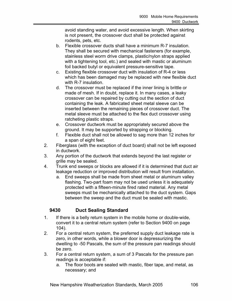
9000 Mobile Home Requirements 9400 Ductwork
New Hampshire Weatherization Standards, March 2005 106
avoid standing water, and avoid excessive length. When skirting is not present, the crossover duct shall be protected against rodents, pets, etc.
b. Flexible crossover ducts shall have a minimum R-7 insulation. They shall be secured with mechanical fasteners (for example, stainless steel worm drive clamps, plastic/nylon straps applied with a tightening tool, etc.) and sealed with mastic or aluminum foil backed butyl or equivalent pressure-sensitive tape.
c. Existing flexible crossover duct with insulation of R-4 or less which has been damaged may be replaced with new flexible duct with R-7 insulation.
d. The crossover must be replaced if the inner lining is brittle or made of mesh. If in doubt, replace it. In many cases, a leaky crossover can be repaired by cutting out the section of duct containing the leak. A fabricated sheet metal sleeve can be inserted between the remaining pieces of crossover duct. The metal sleeve must be attached to the flex duct crossover using ratcheting plastic straps.
e. Crossover ductwork must be appropriately secured above the ground. It may be supported by strapping or blocking.
f. Flexible duct shall not be allowed to sag more than 12 inches for a span of eight feet.
2. Fiberglass (with the exception of duct board) shall not be left exposed in ductwork.
3. Any portion of the ductwork that extends beyond the last register or grille may be sealed.
4. Trunk end sweeps or blocks are allowed if it is determined that duct air leakage reduction or improved distribution will result from installation. a. End sweeps shall be made from sheet metal or aluminum valley
flashing. Two-part foam may not be used unless it is adequately protected with a fifteen-minute fired rated material. Any metal sweeps must be mechanically attached to the duct system. Gaps between the sweep and the duct must be sealed with mastic.
9430 Duct Sealing Standard 1. If there is a belly return system in the mobile home or double-wide,
convert it to a central return system (refer to Section 9400 on page 104).
2. For a central return system, the preferred supply duct leakage rate is zero, in other words, while a blower door is depressurizing the dwelling to -50 Pascals, the sum of the pressure pan readings should be zero.
3. For a central return system, a sum of 3 Pascals for the pressure pan readings is acceptable if: a. The floor boots are sealed with mastic, fiber tape, and metal, as
necessary; and

9000 Mobile Home Requirements 9500 Floor (Belly) Insulation
New Hampshire Weatherization Standards, March 2005 107
b. The end of the supply trunk ducts is sealed. c. Goal: Attempt to reduce the sum of the pressure pan readings to
0 Pascals. 4. For a central return system, a sum of 5 Pascals for the pressure pan
readings is acceptable if: a. The floor boots are sealed with mastic, as necessary; b. The end of the supply truck ducts are sealed; c. Any crossover ducts are visually inspected, repaired and sealed,
as necessary (make sure these ducts are supported properly); and
d. The furnace plenum is sealed with mastic, fiber tape, and metal, as necessary.
Goal: Attempt to reduce the sum of the pressure pan readings to between 0 and 3 Pascals.
5. If difficulty is experienced meeting the goals, use a "pillow" (fiberglass insulation inside of a plastic bag) to block and segment sections of the ducted system to assist in finding leaks.
9500 Floor (Belly) Insulation
9510 Floor Insulation Requirements 1. Belly rodent barriers must be inspected for general condition,
structural strength, and major air leakage, prior to installing insulation. 2. Belly rodent barrier repairs must be made if additional insulation will
be added or if holes in the belly allow significant air movement between the belly cavity and the outside atmosphere.
3. Belly cavities must be inspected to determine the location of the plumbing, any existing plumbing leaks, and the R-value of existing insulation. Leaks should be fixed prior to weatherization.
4. If water pipes are located at the bottom of the belly rodent barrier and it is not possible to get at least two inches of insulation between the pipes and the rodent barrier, then the following must be attempted, if cost effective and feasible: a. The pipes must either be insulated with additional insulation,
either inside the belly or on the exterior of the rodent barrier; or b. The pipes shall be moved closer to the floor above or the
insulation above the pipes should be removed. Note: If these items cannot be completed, then the belly shall be insulated using the perimeter method.
5. Belly insulation shall be installed only after all repairs have been made, major holes in the rodent barrier and floor have been sealed, and all ductwork has been sealed according to Section 9430 on page 106.

9000 Mobile Home Requirements 9500 Floor (Belly) Insulation
New Hampshire Weatherization Standards, March 2005 108
6. Belly insulation must be installed in such a manner that ensures complete coverage under heated areas except those areas requiring and receiving a waiver.
7. Holes that have been made in belly rodent barriers for the installation of insulation must be patched and sealed.
8. Rim joists may not be drilled if they are determined to be a structural component of the foundation support system.
9. Average insulation densities for loose fill insulation installed in mobile home bellies shall be: a. Fiberglass – 1.25 to 1.75 pounds per cubic foot
10. Bellies shall not be dense-packed or over filled so as to create undue stress on the belly rodent barrier.
9520 Floor Insulation Methods 1. Fiberglass is the preferred insulation material for mobile home bellies. 2. Bellies that are 8 inches height and less in the center area shall be
filled entirely with insulation blown at the required densities. 3. Bellies that are greater than 8 inches in height at the center area shall
be insulated using the perimeter method only after attempts have been made to bring the rodent barrier closer to the floor above. This must be done with care to avoid damaging the duct trunk line or water lines in the belly.
4. Perimeter Method: Access through the rim joist and the use of a metal fill tube is preferred for installing mobile home belly insulation whenever possible.
5. Belly Method: If bellies cannot be insulated through the rim joist and must be insulated from underneath, the use of the insulation hose or a large diameter fill tube is preferred. A 90-degree nozzle may not be used.
6. When insulation has to be installed from underneath the belly, the installation of a 6 mil vapor barrier on the ground by the first person to go underneath is preferred, in order to reduce health risks to the installers from animal feces.
7. The preferred methods of securing belly patches are through the use of adhesives, stitch staples, screws, and lath strips whenever possible to provide a lasting patch.
8. Preferred patching materials for large holes in belly rodent barriers include insulated sheathing board, fiberboard, and nylon reinforced belly bottom material specifically manufactured for mobile homes.
9. Ductwork shall be inspected for insulation that might have accidentally entered during insulation work. In addition, cycle the furnace to confirm proper operation.
10. Upon completion of insulation work, rim joists that have been drilled shall be plugged with a wood plug. The plug shall be sealed in the hole with an adhesive compound.

9000 Mobile Home Requirements 9700 Water Pipe Insulation
New Hampshire Weatherization Standards, March 2005 109
9600 Sidewall Insulation
9610 Sidewall Insulation Requirements 1. Mobile home sidewalls should be insulated when the NEAT audit
shows it is cost-effective. 2. The exterior siding and the interior wall materials must be inspected
prior to the installation of insulation. 3. Weak or damaged wall materials must be repaired or reinforced prior
to installing insulation. 4. Electrical precautions:
a. If aluminum wiring is present, extra care must be taken to insure the electrical system is not damaged during insulation work. The following steps must be taken:
i. Each cavity that contains an outlet, switch, or light fixture should be clearly identified and marked on the outside siding prior to the installation of the insulation, and these cavities should be carefully tubed rather than stuffed with a batt or, if excessive movement of the wires will still occur, then the cavity should not be insulated.
ii. Each outlet, switch, or light fixture must be checked with a receptacle tester for proper operation before and immediately following the completion of the insulation work.
b. If any one of the above two steps cannot be completed, the sidewalls shall not be insulated and documentation stating the reason for omission must be placed in the client file.
5. Installing insulation above windows and doors is usually not feasible or cost-effective and is not required in mobile homes.
6. Mobile home sidewalls shall not be dense-packed or over filled so as to create siding or interior wall structural problems.
9620 Sidewall Insulation Methods 1. Poly-wrapped fiberglass batt insulation and loose fill fiberglass are the
preferred insulation materials for mobile home sidewalls. 2. The batt-stuffing method is the favored technique for insulating wall
cavities. 3. For cavities that cannot or should not be insulated with the batt-stuff
technique, the fill-tube method with loose fill fiberglass is recommended.
9700 Water Pipe Insulation 1. Water pipes that have not been covered by under-floor insulation
should be insulated to a minimum of R-3. 2. The piping shall be free from water leaks and properly secured to
support the weight of the piping and insulation.

9000 Mobile Home Requirements 9800 Water Heater Closets and Tanks
New Hampshire Weatherization Standards, March 2005 110
3. The insulation product may be flat and capable of being molded to the outside surface of common pipe size or preformed to fit standard pipe diameters. If the product is preformed, dimensions shall be appropriate for the pipe size.
4. If the insulation is exposed to the weather, it shall be resistant to degradation from moisture, ultra-violet light, and extremes in temperature, or a jacket or facing shall be installed that protects the insulation from these conditions.
9800 Water Heater Closets and Tanks 1. At a minimum, water heater closets with an exterior wall must be
treated as follows: a. The exterior access door and associated exterior walls of closets
containing electric or gas water heaters shall be insulated. i. Cover air vents if they are present in the door or associated
exterior wall. ii. Bring combustion air from underneath the belly or through
the skirting by installing an appropriately sized metal chute with a rodent barrier.
b. If it is not possible to insulate the closet door and associated wall area:
i. The tank should be wrapped with an insulation blanket. Please refer to Section 5310 on page 56 for instructions.
ii. Large holes in the closet walls that allow air leakage into the interior must be sealed.
iii. All plumbing within the closet that is susceptible to freezing must be insulated.
iv. An adequate amount of combustion air must be provided to gas water heaters.

10000 Glossary
New Hampshire Weatherization Standards, March 2005 111
10000 Glossary
- A - Abatement – A measure or set of measures designed to permanently eliminate a hazard (i.e. lead based paint). Abatement strategies include removal of the hazardous materials, replacement of building components containing the hazardous material, enclosure, or encapsulation. All of these strategies require proper preparation, cleanup, waste disposal post abatement clearance testing, and if applicable, record keeping and monitoring. Absorption – Absorption is the process by which a substance can be readily taken into the body through the skin or membranes. The best defense is to have a protective barrier between the substance and the skin. AFUE – Annual Fuel Utilization Efficiency – A laboratory derived efficiency for heating appliances, which accounts for chimney losses, jacket losses, and cycling losses, but not distribution losses or fan/pump energy. Air Changes per Hour at 50 Pascals (ACH50) – The number of times that the complete volume of a home is exchanged for outside air in one hour when a blower door depressurizes or pressurizes the home to 50 Pa. Air Changes per Hour natural (ACHnat) – The number of times the indoor air is exchanged with the outdoor air in one hour under natural driving forces. It can be estimated with blower door use. Air exchange – The process where indoor air is replaced with the outdoor air through air leakage and ventilation. One CFM out equals one CFM in. Air handler – A steel cabinet containing a blower with cooling and/or heating coils connected to ducts, which circulates indoor air across the exchangers and into the living space. Air infiltration barrier – A spun polymer sheet (for example, house wrap) that stops almost all the air traveling through a building cavity, while allowing moisture to pass through it. Air-Free Carbon Monoxide – A method used to be able to compare CO readings with varying amounts of dilution air (oxygen) mixed in. The air-free method adjusts air content (oxygen) to zero.

10000 Glossary
New Hampshire Weatherization Standards, March 2005 112
Altitude Adjustment – When a gas appliance is installed more than 2000 feet above sea level, its input rating must be reduced by approximately four percent per 1000 feet above sea level. Ambient air – Air in the living space. Ampere – A unit of measurement that tells how much electricity flows through a conductor. It is like cubic feet per second to measure the flow of water. For example, a 1,200-watt, 120-volt hair dryer pulls 10 amperes of electric current (watts divided by volts). ANSI – American National Standards Institute, Inc. Aquastat – A heating control that switches the burner or the circulator pump in a hydronic heating system. Asbestos – A fibrous mineral with fireproof and insulation characteristics which may be shaped into a variety of building materials. Small, sharp asbestos fibers may cause damage to lungs if they are inhaled. ASHRAE – American Society of Heating, Refrigerating, and Air-Conditioning Engineers, Inc. ASME – American Society of Mechanical Engineers. ASTM – American Society for Testing and Materials. Atmospheric appliances – A heating device that takes its combustion air from the surrounding room air. Also, know as open-combustion heater.
- B -
Backdrafting – Continuous spillage of combustion gases from a vented combustion appliance into the living space. Backdraft damper – A damper, installed near a fan, that allows air to flow in only one direction and prevents reverse flow when the fan is off. Backer rod – Polyethylene foam rope used as a backer for caulking. Baffle – A plate or strip designed to retard or redirect the flow of flue gases. Balance point – The outdoor temperature at which no heating is needed to maintain inside temperatures.

10000 Glossary
New Hampshire Weatherization Standards, March 2005 113
Balloon framing – A method of construction in which the vertical framing members (studs) are continuous pieces running the entire height of the wall. Band joist – See Rim joist. Barometric vent damper – a device installed in the heating unit vent system to control draft. Usually used on oil-fueled units or gas units with power burners. Batt – A blanket of preformed insulation, generally 14.5" or 22.5" wide, and varying in thickness from 3.5" to 9". BDL – See Building Depressurization Limit. Belly return – A configuration found in some mobile homes that uses the belly cavity as the return side of the distribution system. Benefit-to-Cost Ratio (BCR) – See Savings-to-Investment Ratio (SIR). Bimetal element – A metal spring, lever, or disc made of two dissimilar metals that expand and contract at different rates as the temperature around them changes. This movement operates a switch in the control circuit of a heating or cooling device. Blocking – A building element or material used to prevent movement into or through building cavities. Blow-down – Removing water from a boiler to remove sediment and suspended particulates. Blower – The "squirrel-cage" fan in a furnace or air handler. Blower door – A calibrated device to measure the air tightness of a building by pressurizing or depressurizing the building and measuring the flow through the fan. Blown insulation – A loose-fill insulation that is blown into attics and building cavities using an insulation blowing machine. Boot – A duct section that connects between a duct and a register, floor, or wall cavity or between round and square ducts. Branch circuit – An electrical circuit used to power outlets and lights within a home. British Thermal Unit (Btu) – The quantity of heat required at sea level to raise the temperature of one pound of water one degree Fahrenheit.

10000 Glossary
New Hampshire Weatherization Standards, March 2005 114
BTL – BTL calculation procedure, expressed in units of CFM50, based on the American Society of Heating, Refrigerating and Air-Conditioning Engineers Standard 62-1999, Ventilation for Acceptable Indoor Air Quality. This method was clearly explained in an article in Home Energy magazine (Tsongas 1993). The method closely follows the parameters set in ASHRAE 62-1999: For acceptable indoor air quality, 15 CFM per person (set minimum of five people) or 0.35 air changes per hour (ACH), whichever is greater, must be supplied by natural air leakage and/or continuously operating ventilation. BTLa – BTLa calculation procedure, expressed in units of CFM50, that is more complex than the BTL method and is based on ASHRAE Standard 62, Standard 119 (Air Leakage Performance for Detached Single-Family Residential Buildings), and Standard 136 (A Method of Determining Air Change Rates in Detached Dwellings). This method closely follows the parameters set in ASHRAE 62-1999: For acceptable indoor air quality, 15 CFM per person or 0.35 air changes per hour (ACH), whichever is greater, must be supplied by natural air leakage and/or continuously operating ventilation. However, the BTLa method uses different calculation methods – based on ASHRAE 119 and 136 – than the BTL method to arrive at the final tightness limits. Btuh – British thermal units per hour. Building cavities – The spaces inside walls, floors, and ceilings or between the interior and exterior sheeting. Building Depressurization Limit – A selected indoor negative pressure; expressed in Pascals, immediately around vented combustion appliances that use indoor air for combustion supply air. If a combustion appliance experiences a negative pressure of a greater magnitude than the BDL, it has the potential to backdraft, causing a hazardous condition for the occupants. The BDL for furnaces and boilers is often -5 Pascals and for stand-alone natural draft water heaters, -2 Pascals. Field studies have been done to determine the negative pressure at which these appliances will begin to backdraft. Building science – An involved perspective on buildings, using contemporary technology to analyze and solve problems dealing with design, construction, maintenance, safety, and energy efficiency of the buildings. Burner – A device that facilitates the burning of a fossil fuel like gas or oil. Bypass – An air leakage site that allows air to leak out of a building passing around the air barrier and insulation.

10000 Glossary
New Hampshire Weatherization Standards, March 2005 115
- C - Carbon dioxide (CO2) – A heavy, colorless, nonflammable gas formed by the oxidation of carbon, by combustion, and in respiration of plants and animals. Carbon monoxide (CO) – An odorless, colorless, tasteless, and poisonous gas produced by incomplete combustion. Category I gas appliance – As defined by NFPA 54, a combustion appliance that has negative pressure in the vent connector relative to the air around the vent connector and the appliance is not a condensing unit. Caulking – A mastic compound for filling joints and cracks. CAZ – See Combustion Appliance Zone. Cellulose insulation – Insulation, packaged in bags for blowing, made from newspaper or wood waste and treated with a fire retardant. CFM – Cubic Feet per Minute – A measurement of air movement in cubic feet past a certain point or through a certain structure per minute. CFM50 – The number of cubic feet per minute of air flowing through the fan housing of a blower door when the house pressure is 50 Pa (0.2 inches of water column). This figure is the most common and accurate way of comparing the tightness of buildings that are tested using a blower door. CFMnat – The number of cubic feet of air flowing through a house from indoors to outdoors during typical, natural conditions. This figure can be roughly estimated using a blower door using the LBL (Lawrence Berkeley Labs) infiltration model. Chimney – A building component designed for the sole purpose of assuring combustion by-products are exhausted to the exterior of the building. Circuit breaker – A device that automatically disconnects an electrical circuit from electricity under a specified or abnormal condition of current flow. Cold Air Return (Return side): Ductwork through which house air is drawn for reheating during furnace cycle. Combustible – Susceptible to combustion; inflammable; any substance that will burn. Combustible Gas Leak Detector – A device for determining the presence and general location of combustible gases in the air.

10000 Glossary
New Hampshire Weatherization Standards, March 2005 116
Combustion – The act or process of burning. Oxygen, fuel, and a spark must be present for combustion to occur. Combustion air – Air required to chemically combine with a fuel during combustion to produce heat and flue gases, mainly carbon dioxide and water vapor. Combustion analyzer – A device used to measure steady-state efficiency of combustion heating units. Combustion appliance – Any appliance in which combustion occurs. Combustion Appliance Zone (CAZ) – The closed space or area, which holds one or more combustion appliances. Combustion chamber – The area inside a heating unit where combustion takes place. Compact fluorescent light (CFL) – A small fluorescent light engineered to fit conventional incandescent fixtures. Compressor – A motorized pump that compresses the gaseous refrigerant and sends it to the condenser where heat is released. Condense – To change from a gaseous or vaporous state to a liquid or solid state by cooling or compression. Condenser – The coil in an air conditioning system where the refrigerant condenses and releases heat, which is carried away by air moving across the coil. Condensate – The liquid formed when a vapor is condensed. Condensate receiver – A tank for catching returning condensate water from a steam heating system. Conditioned Space –Conditioned space includes any area of a dwelling that is determined to be within the insulated envelope or shell. Conductance – The quantity of heat, in Btu, that will flow through one square foot of material in one hour, when there is a one degree Fahrenheit temperature difference between both surfaces. Conductance values are given for a specific thickness of material, not per inch thickness.

10000 Glossary
New Hampshire Weatherization Standards, March 2005 117
Conduction – The transfer of heat energy through a material (solid, liquid or gas) by the motion of adjacent atoms and molecules without gross displacement of the particles. Conductivity – The quantity of heat that will flow through one square foot of homogeneous material, one inch thick, in one hour, when there is a temperature difference of one degree Fahrenheit between its surfaces. Confined space – A space with a volume of less than 50 cubic feet per 1,000 Btu per hour of the total input rating of all combustion appliances installed in that space. Contractor – Any for-profit, not-for-profit, or government entity that provides services to the program under contract, not as a result of a grant of funds. Control circuit – A circuit whose work is switching a power circuit or opening an automatic valve. Convection – The transmission of heat by the actual movement of a fluid because of differences in temperature, density, etc. Conventionally vented combustion appliance – Combustion appliances that are characterized by atmospheric burners or natural draft. Sealed or direct-vent appliances are not conventionally vented. Cooling load – The maximum rate of heat removal required of an air conditioner when the outdoor temperature and humidity are at the highest expected level. Cost-effective – Having an acceptable payback, return-on-investment, or savings-to-investment ratio. Critical framing juncture – An intersection of framing members and envelope components that require special attention during prep and installation of insulation. Cross section – A view of a building component drawn or imagined by cutting through the component.

10000 Glossary
New Hampshire Weatherization Standards, March 2005 118
- D - Degree-days (DD) – A measure of the temperature element of climate produced by summing the temperature differences between the inside (65°F) and the daily average outside temperature for a one-year period. Demand – The peak need for electrical energy. Some utilities levy a monthly charge for demand. Density – The weight of a material divided by its volume, usually measured in pounds per cubic foot. Depressurize - To lower the pressure in an enclosed area with respect to a reference pressure. Depressurization Tightness Limit (DTL) – A calculation procedure, expressed in units of CFM50, performed to estimate the building tightness level at which combustion appliances might backdraft when the house is under conditions of worst-case depressurization. The DTL sets a low limit for air sealing that may or may not be lower than the BTLa for the same house. Design temperature - A high or low temperature used for designing heating and cooling systems when calculating the building load. Dilution air - Air that enters through the dilution device-an opening where the chimney joins to an atmospheric-draft combustion appliance. Dilution device - A draft diverter, draft hood, or barometric draft control on an atmospheric-draft combustion appliance. Direct-vent appliance - Appliances that are constructed and installed so that all combustion air is taken directly from and the flue gases are vented directly to the outside. Distribution system - A system of pipes or ducts used to distribute energy. DHW - Domestic Hot Water. DOE - The United States Department of Energy. Dormer - A framed structure projecting above a sloping roof surface, and normally containing a vertical window.

10000 Glossary
New Hampshire Weatherization Standards, March 2005 119
Draft diverter - A device built into an appliance or made a part of the vent connector for an appliance that is designed to: 1) provide for the ready escape of the flue gasses from the appliance in the event of no draft, backdraft, or stoppage beyond the draft hood, 2) prevent a backdraft from entering the appliance, and 3) neutralize the effect of stack action of the chimney or gas vent upon the operation of the appliance. Drywall - Gypsum interior wallboard used to produce a smooth and level interior wall surface and to resist fire. Also called gypsum wallboard and sheetrock. Dry bulb temperature - Normal ambient air temperature measured by a thermometer. DTL – See Depressurization Tightness Limit. Duct blower - A blower-door-like device used for testing duct leakiness and air flow. Duct zone - A building space or cavity that contains heating or cooling ducts.
- E - Eave - The part of a roof that projects beyond its supporting walls. See also soffit. EEM - Energy efficiency measure. Efficiency - The ratio of output divided by input. Electric service - The electric meter and main switch, usually located outside the building. Emittance - The rate that a material emits radiant energy from its surface. Also called emissivity. Encapsulation - Any covering or coating that acts as a barrier between the hazard (i.e. lead-based paint) and the environment, the durability of which relies on adhesion and the integrity of existing bonds between any existing layers (i.e. paint) and the substrate. Enclosure - The use of rigid, durable construction materials that are mechanically fastened to the substrate to act as a barrier between the hazardous material (i.e. lead-based paint) and the environment. Energy - A quantity of heat or work.

10000 Glossary
New Hampshire Weatherization Standards, March 2005 120
Energy audit - The process of identifying energy conservation opportunities in buildings. Energy consumption - The conversion or transformation of potential energy into kinetic energy for heat, light, electricity, etc. Energy efficiency - Term describing how efficiently a building component uses energy. Energy efficiency ratio (EER) - A measurement of energy efficiency for room air conditioners. The EER is computed by dividing cooling capacity, measured in British Thermal Units per hour (Btuh), by the watts of power. (See also Seasonal Energy Efficiency Rating - SEER) Envelope - The building shell. The exterior walls, floor, and roof assembly of a building. Environmentally sensitive - A person who is highly sensitive to pollutants, often because of overexposure, is said to be environmentally sensitive. Evaporation - The process of being changed into a vapor or gas at a temperature usually below the boiling point. Evaporation is a cooling process. Evaporative cooler - A device for cooling homes in dry climates that cools the incoming air through the evaporation of water. Evaporator - The heat transfer coil of an air conditioner or heat pump that cools the surrounding air as the refrigerant inside the coil evaporates and absorbs heat. Exfiltration - Air flowing out of a building from its conditioned space through the holes in the shell.
- F - Fahrenheit - A temperature scale for which water boils at 212° and freezes at 32°. Fan control - A bimetal thermostat that turns the furnace blower on and off as it senses the presence of heat. Fan-off temperature - In a furnace, the supply air temperature at which the fan control shuts down the distribution blower.

10000 Glossary
New Hampshire Weatherization Standards, March 2005 121
Fan-on temperature - In a furnace, the supply air temperature at which the fan control activates the distribution blower. Feeder wires - The wires connecting the electric meter and main switch with the main panel box indoors. Fenestration - Window and door openings in a building’s wall. Fiberglass - A fibrous material made by spinning molten glass. Fill tube - A plastic or metal tube used for its stiffness to blow insulation inside a building cavity and allows the insulation to be delivered at the extreme end of the cavity. Fire stop - Framing member, usually installed horizontally between studs, designed to stop the spread of fire within a wall cavity. Flame safety control - A control for avoiding fuel delivery in the event of no ignition. Flammable/Inflammable - Combustible; readily set on fire. Flashing - Waterproof material used to prevent leakage at intersections between the roof surface at walls or penetrations. Floor joists - The framing members that support the floor. Flue - A vent for combustion gases. Foam board - Plastic foam insulation manufactured most commonly in 4' x 8' sheets in thicknesses of ½" to 3". Footing - The part of a foundation system that transfers the weight of the building to the ground. Friable – Applies to easily crumbled or pulverized materials, particularly asbestos, that may become airborne. Frost line - The maximum depth of the soil where water will freeze during the coldest weather. Furring - Thin wood strips fastened to a wall or ceiling surface as a nailing base for finish materials.

10000 Glossary
New Hampshire Weatherization Standards, March 2005 122
- G - Gable - The triangular section of an end wall formed by the pitch of the roof. Gable roof - A roof shape that has a ridge at the center and slopes in two directions. GAMA - Gas Appliance Manufacturers’ Association Gasket - Elastic strip that seals a joint between two materials. General heat waste – Weatherization measures for which savings or savings-to-investment ratios (SIR) are difficult or impossible to calculate. Examples include all air sealing work, ductwork sealing and insulation, pipe insulation, and dryer vent kit installation. No SIR values are required for these measures. Glazing - Glass installation. Pertaining to glass assemblies or windows. Glazing compound - A flexible, putty-like material used to seal glass in its sash or frame. Ground Fault Circuit Interrupter (GFI or GFCI) - An electrical connection device that breaks a circuit if a short occurs. These are required for all exterior use of electrical equipment or when an electrical outlet is located near a water source. Gypsum board - A common interior sheeting material for walls and ceilings made of gypsum rock powder packaged between two sheets of heavy building paper. Also called sheetrock, gyprock, or gypboard.
- H - Habitable Space – A building space intended for continual human occupancy. Examples include areas used for sleeping, dining, and cooking, but not bathrooms, toilets, hallways, storage areas, closets, or utility rooms. See occupiable space and conditioned space. Hazardous condition - A situation that is causing a danger to the client/crew/contractor/contractor that exists before, is created by, or is exacerbated by, weatherization. For example, a dwelling could have a moisture problem that is allowing biological hazards (molds, viruses, bacteria, etc.) to flourish. Another example would be allowing fiberglass to enter the living space due to improperly fastened or sealed ductwork.

10000 Glossary
New Hampshire Weatherization Standards, March 2005 123
Hazardous material - A particular substance that is considered a danger to the client/crew/contractor/contractor. Heat anticipator - A very small electric heater in a thermostat that causes the thermostat to turn off before room temperature reaches the thermostat setting, so that the house does not overheat from heat remaining in the furnace and distribution system after the burner shuts off. Heat capacity - The quantity of heat required to produce a unit of temperature change. Heat exchanger - The area in a heating unit that separates the combustion process from the distribution fluid, with the sole purpose of transferring heat from the combustion process to the distribution fluid. Heat loss - The amount of heat escaping through the building shell during a specified period. Heat pump - A type of heating/cooling unit, usually electric, that uses a refrigerant fluid to heat and cool a space. Heat rise - In a furnace, the number of degrees of temperature increase that air is heated as it is blown over the heat exchanger. Heat rise equals air supply temperature minus air return temperature. Heating degree day (HDD) - Each degree that the average daily temperature is below the base temperature (usually 65°F) constitutes one heating degree day. Heating load - The maximum amount of heat needed by a building during the very coldest weather to maintain the designed inside temperature. Heating seasonal performance factor (HSPF) - Rating for heat pumps describing how many Btus they transfer per kilowatt-hour of electricity consumed. HHS - United States Department of Health and Human Services. High limit - A bimetal thermostat that turns the heating element of a furnace off if it senses a dangerously high temperature. Hip Roof - A roof that slants in four directions from a central peak. Home energy index - The number of Btus of energy used by a home divided by its area of conditioned square feet and by the number of heating degree days during one year. House pressure - The difference in pressure between the inside and outside of the house. HUD - United States Department of Housing and Urban Development.

10000 Glossary
New Hampshire Weatherization Standards, March 2005 124
Humidistat - An automatic control that switches a fan, humidifier, or dehumidifier on and off based on the relative humidity at the control. Humidity ratio - The absolute amount of air’s humidity measured in pounds of water vapor per pound of dry air. HVAC - Heating, Ventilating, Air-Conditioning. HVI - Home Ventilating Institute. Hydronic - A heating system using hot water or steam as the heat-transfer fluid. A hot-water heating system (common usage).
- I - IAQ - Indoor Air Quality Illumination - The light level measured on a horizontal plane in foot-candles. Incandescent light - The common light bulb found in residential lamps and light fixtures and sold in stores everywhere that is known for its inefficiency. Infiltration - The uncontrolled movement of non-conditioned air into a conditioned air space. Ingestion - Ingestion is the process by which a substance enters the body by swallowing through the mouth. The best defense is to wash your hands before eating or putting your fingers in your mouth, keeping hazardous materials out of reach from small children, and guarding against splashing of hazardous materials into your mouth. Inhalation - Inhalation is the process by which a substance is breathed into the body in the form of a gas, vapor, fume, mist, or dust. The best defense is to use a proper filter to remove these contaminants before they enter the body or to not create dust if possible. Input rating - The designed capacity of an appliance usually specified in Btus or units of energy. Insulating glass - Two or more glass panes spaced apart and sealed in a factory giving a higher R-value. Insulation - A material used to retard heat transfer.

10000 Glossary
New Hampshire Weatherization Standards, March 2005 125
Intermittent ignition device (IID) - A device that lights the pilot light on a gas appliance when the control system calls for heat, thus saving the energy wasted by a standing pilot. Internal gains - The heat generated by bathing, cooking, and operating appliances that must be removed during the summer to promote comfort or will reduce the heating demand in the winter. Interstitial - Space between framing and other building components.
- J -
Joist - A horizontal wood framing member that supports a floor or ceiling. Joule - A unit of energy. One thousand joules equals 1 Btu.
- K - Kilowatt - One thousand watts. A unit of measurement of the amount of electricity needed to operate given equipment. Kilowatt-hour - The most commonly used unit for measuring the amount of electricity consumed over time. It means one kilowatt of electricity supplied for one hour. Kinetic energy - Consisting of or depending on motion; distinguished from potential energy.
- L - Latent heat - The amount of heat energy required to change the state of a substance from a solid to a liquid or from a liquid to a gas without changing the temperature of the substance. Lath - A thin strip of wood or base of metal or gypsum board serving as a support for plaster. Living space – A space in a dwelling that is lived in or regularly occupied. This space may be conditioned or unconditioned. Low-E - Short for low emissivity, which refers to the characteristic of a metallic glass coating to resist the flow of radiant heat.

10000 Glossary
New Hampshire Weatherization Standards, March 2005 126
Low-water cutoff - A float-operated control for turning the burner off if a steam boiler is low on water.
- M - Main panel box - The service box containing a main switch, and the fuses or circuit breakers located inside the home. Make-up air - Air supplied to a space to replace exhausted air. Manifold - A tube with one inlet and multiple outlets or multiple inlets and one outlet. Manometer - A pressure differential gauge used for measuring gas and air pressures. Masonry - Construction of stone, brick, or concrete block. Mastic - A thick creamy substance used to seal seams and cracks in building materials and especially useful on ductwork. Metabolic process - Chemical and physiological activities in the human body. Mitigate - To make less severe. Mortar - A mixture of sand, water, and cement used to bond bricks, stones, or blocks together. MSDS - Materials Safety Data Sheet.
- N -
Natural ventilation - Ventilation using only natural air movement, without fans or other mechanical devices. NBS - The National Bureau of Standards, Department of Commerce renamed the National Institute of Standards and Technology (NIST). NEAT - National Energy AudiT, developed by DOE for weatherization. Used to audit single-family and low-rise multi-family buildings. NEMA - National Electrical Manufacturers’ Association.

10000 Glossary
New Hampshire Weatherization Standards, March 2005 127
Net Free Vent Area (NFVA) - The area of a vent after that area has been adjusted for the restrictions caused by insect screen, louvers, and weather coverings. The free area is always less than the actual area. NFPA - National Fire Protection Association. Non-conditioned space - An area within the building envelope that is not heated or cooled and tends to be the same temperature as outside. Nozzle - An orifice designed to change a liquid like oil into a mist to improve the combustion process. NWMA - National Woodwork Manufacturers Association.
- O - O2 - Oxygen. Occupiable Space – An enclosed space inside the pressure boundary of a room or house, and intended for human activities including, but not limited to, all habitable spaces, bathrooms, closets, halls, storage and utility areas, and laundry areas. See habitable space and conditioned space. Ohm - A unit of measure of electrical resistance. One volt can produce a current of one ampere through a resistance on one ohm. Orifice - A hole in a gas pipe where gas exits the pipe to be mixed with air in a burner before combustion in a heating device. The size of the orifice will help determine the flow rate. Output capacity - The conversion rate of useful heat or work that a device produces after waste involved in the energy transfer is accounted for. Oxygen Depletion Sensor (ODS) - A safety device for unvented (vent-free) combustion heaters that shuts off gas when oxygen is depleted.
- P - Parts per million (ppm) - The unit commonly used to represent the degree of pollutant concentration where the concentrations are small. Pascal (Pa) - A metric unit of measurement of air pressure. 2.5 Pa = 0.01 inches of water column.

10000 Glossary
New Hampshire Weatherization Standards, March 2005 128
Payback period - The number of years that an investment in energy conservation will take to repay its cost in energy savings. Perimeter pull - A technique used in attics previously insulated with batt insulation. The batts are cut back 2 feet from the eaves and the area is insulated with blown insulation to ensure coverage over the outer wall top plate and to prevent wind washing of the insulation under the existing batts. Perlite - A heat-expanded mineral used for insulation. Perm - A measurement of how much water vapor a material will let pass through it per unit of time under a specified pressure difference. Pilot tube - A device for measuring fluid velocity. An instrument placed in a moving fluid and used along with a manometer to measure fluid velocity. Plaster - A plastic mixture of sand, lime, and Portland cement spread over wood or metal lathe to form the interior surfaces of walls and ceilings. Plate - A piece framing member installed horizontally to which the vertical studs in a wall frame are attached. Plenum - The section of ductwork that connects the air handler to the main supply duct. Plywood - Laminated wood sheeting with layers cross grained to each other. Polyethylene - A plastic made by the polymerization of ethylene, used in making translucent, lightweight, and tough plastics, films, insulations, vapor retarders, air barriers, etc. Polyisocyanurate - Plastic foam insulation sold in sheets, similar in composition to polyurethane. Polystyrene insulation - rigid plastic foam insulation, usually white, blue, pink, or green in color. Polyurethane - versatile plastic foam insulation, usually yellow in color. Potential energy - Energy in a stored or packaged form. Pressure - A force that encourages movement by virtue of a difference in some condition between two areas. High pressure moves to low pressure.

10000 Glossary
New Hampshire Weatherization Standards, March 2005 129
Pressure diagnostics - The practice of measuring pressures and flows in buildings to control air leakage, and to ensure adequate heating and cooling airflows and ventilation. Pressure pan - A device used to block a duct register, while measuring the pressure behind it. Pressure Relief Valve - A safety component required on a boiler and water heater, designed to relieve excess pressure buildup in the tank. Pressuretrol - A control that turns a steam boiler’s burner on and off as steam pressure changes. Primary window - The main window installed on the outside wall. Not to be confused with a storm window. Provider - Either a grantee or contractor.
- R -
Radiant barrier - A foil sheet or coating designed to reflect radiant heat flow. Radiant barriers are not mass insulating materials. Radiant temperature - The average temperature of objects in a home, including walls, ceiling, floor, furniture, and other objects. Radiation - Heat energy that is transferred by electromagnetic or infrared light from one object to another. Radiant heat flow can travel through a vacuum and other transparent materials. Radon - A radioactive gas that decomposes into radioactive particles. Rafter - A beam that gives form and support to a roof. Rated ventilation - A ventilation system that has been designed and installed under the guidelines established by the American Society of Heating, Refrigeration, and Air Conditioning Engineers (ASHRAE) Standard for Acceptable Indoor Air Quality (Standard 62). RCS - Residential Conservation Service Program. Reflectance - The ratio of lamination or radiant heat reflected from a given surface to the total light falling on it. Also called reflectivity.

10000 Glossary
New Hampshire Weatherization Standards, March 2005 130
Refrigerant - Any of various liquids that vaporize at a low temperature, used in mechanical refrigeration. Register - A grille covering a duct supply outlet used to diffuse the airflow and sometimes control the flow. Relative humidity - The percent of moisture present in the air compared to the maximum amount possible at that given temperature. Air that is saturated has 100% relative humidity. Relay - An automatic, electrically operated switch. Reset controller - Adjusts fluid temperature or pressure in a central heating system according to outdoor air temperature. Resistance - The property of a material resisting the flow of electrical energy or heat energy. Retrofit - An energy conservation measure that is applied to an existing building. Also means the action of improving the thermal performance or maintenance of a building. Return air - Air circulating back to the furnace or central air conditioning unit from the house, to be heated or cooled and supplied back to the living area. Rim joist - The outermost joist around the perimeter of the floor framing. Rocking on the high limit– Refers to the gas burner being shut down by the high limit switch on a furnace, instead of being properly activated by the fan-on/fan-off control. Room air conditioner - A unitary air conditioner installed through a wall or window, which cools the room by removing heat from the room and releasing it outdoors. R-value - A measurement of thermal resistance.

10000 Glossary
New Hampshire Weatherization Standards, March 2005 131
- S - Sash - A movable or stationary part of a window that frames a piece of glass. Savings-to-Investment Ratio (SIR) – For an energy saving measure, the ratio of the savings over the investment (cost), including the discounting the investment value and escalation of fuel costs. Sealed-combustion appliance - An appliance that draws combustion air from outdoors and has a sealed exhaust system. Also called a direct-vent appliance. Seasonal energy efficiency ratio (SEER) - A measurement of energy efficiency for central air conditioners. The SEER is computed by dividing cooling capacity, measured in Btuh, by the Watts. (See also Energy Efficiency Rating.) Sensible heat - The heat required to change the temperature of a material without changing its form. Sequencer - A bimetal switch that turns on the elements of an electric furnace in sequence. Service wires - The wires coming from the utility transformer to the service equipment of the building. Sheathing - structural sheeting, attached on top of the framing, underneath siding and roofing of a building. Any building material used for covering a building surface. Sheetrock - See drywall. Shell - The building’s exterior envelope—walls, floor, and roof of a building. Shingle - A modular roofing component installed in overlapping rows. Short circuit - A dangerous malfunction in an electrical circuit, where electricity is flowing through conductors and into the ground without going through an electric load, such as a light or motor. Sill - The bottom of a window or doorframe. Sill box - The area bounded by the rim joist, floor joists, sill plate, and floor. Site-built home – Includes a house built on the site from building supplies or manufactured homes assembled on the site from pieces shipped to the site on flatbed trucks. Does not include mobile homes and double-wides.

10000 Glossary
New Hampshire Weatherization Standards, March 2005 132
Sling psychrometer - A device holding two thermometers, one wet bulb and one dry bulb, which is swung through the air to determine relative humidity. Slope - The roof section of a knee wall attic with the roof and ceiling surfaces attached to the rafters. Soffit - The underside of a roof overhang or a small lowered ceiling, as above cabinets or a bathtub. Solar gain - Heat from the sun that is absorbed by a building. Solenoid - A magnetic device that moves a switch or valve stem. Space heating - Heating the living spaces of the home with a room heater or central heating system. Spillage - Temporary reversal of combustion gases in a venting system. Temporary or short-lived backdrafting. Stack effect - The tendency for warm buoyant air to rise and leak out of the top of the house and be replaced by colder outside air entering from the bottom of the house. Steady-state efficiency (SSE) - The efficiency of a heating appliance, after an initial start-up period and while the burner is operating, that measures how much heat crosses the heat exchanger. The steady-state efficiency is measured by a combustion analyzer. Steam trap - An automatic valve that closes to trap steam in a radiator until it condenses. Steam vent - A bimetal-operated air vent that allows air to leave steam piping and radiators, but closes when exposed to steam. Stud - A vertical framing member used to build a wall. Sub floor - The sheathing over the floor joists and under the flooring. Supply air - Air that has been heated or cooled and is then moved through the ducts and out the supply registers of a home. Suspended ceiling - Modular ceiling panels supported by a hanging frame.

10000 Glossary
New Hampshire Weatherization Standards, March 2005 133
- T - Therm - A unit of energy equivalent to 100,000 Btus or 29.3 kilowatt-hours. Thermal break - A piece of relatively low conducting material between two high conducting materials installed to reduce heat flow through the assembly. Thermal bridging - Rapid heat conduction resulting from direct contact between thermally conductive materials like metal and glass. Thermal bypass - An indirect penetration that tends to reduce the effectiveness of insulation by allowing conditioned air to move out of a structure, or allowing unconditioned air to move in, depending on the exerted pressures. Thermal conductance - A material’s ability to transmit heat; the inverse of the R-value. Thermal resistance - Same as R-value, expressing ability to retard heat flow. Thermocouple - A bimetal-junction electric generator used to control the safety valve of an automatic gas valve. Thermostat - A device used to control a heating or cooling system to maintain a set temperature. Transformer - A double coil of wire that reduces or increases voltage from a primary circuit to a secondary circuit. Truss - A braced framework usually in the shape of a triangle to form and support a roof.
- U - U-factor - The total heat transmission in Btus per square feet per hour with a 1°F temperature difference between the inside and the outside; the thermal conductance of a material. Ultraviolet radiation - Light radiation having wavelengths beyond the violet end of the visible spectrum; high frequency light waves. Underlayment - Sheeting installed to provide a smooth, sound base for a finish material. UL - Underwriter’s Laboratory.

10000 Glossary
New Hampshire Weatherization Standards, March 2005 134
- V - Vapor barrier - A material that retards the passage of water vapor. Vapor diffusion - The flow of water vapor through a solid material. Vapor retarder - A vapor barrier. Vaporize - Change from a liquid to a gas. Vent damper - An automatic damper powered by heat or electricity that closes the chimney while a heating device is off. Ventilation - The movement of air through an area for removing moisture, air pollution, or unwanted heat. Venting - The removal of combustion gases by a chimney. Vermiculite - A heat-expanded mineral used for insulation. Volt - A unit of electromotive force. It is the amount of force required to drive a steady current of one ampere through a resistance of one ohm. Electrical systems of most homes in the United States have 120 volt systems.
- W - Watt (W) - A unit measure of electric power at a point in time, as capacity or demand. One Watt of power maintained over time is equal to one joule per second. Watt-hour - One Watt of power extended for one hour. One thousandth of a kilowatt-hour. Weatherization - The process of reducing energy consumption and increasing comfort in buildings by improving energy efficiency of the building and maintaining health and safety. Weatherstripping - Flexible gaskets, often mounted in rigid metal strips, for limiting air leakage. Weep holes - Holes drilled for allowing water to drain out of an area in a building component where it may accumulate. Wet bulb temperature - The temperature of a dampened thermometer of a sling psychrometer used to determine relative humidity.

10000 Glossary
New Hampshire Weatherization Standards, March 2005 135
Window films - Plastic films, coated with a metalized reflective surface, that are adhered to window glass to reflect infrared rays from the sun. Window frame - The sides, top, and sill of the window, which form a box around window sashes and other components. Worst-Case Depressurization - A condition created when 1) all exhaust appliances (bathroom exhaust, kitchen exhaust, vented dryers, etc.) are operating, 2) the interior doors of a house are in a position that causes the greatest negative pressure in the CAZ, and 3) the furnace air handler is operating if such operation causes increased negative pressure in the CAZ. Worst-Case Draft Test - A test that creates worst-case depressurization in a combustion appliance zone (CAZ). This test is used to determine if combustion appliances will vent properly under these worst-case conditions.