Embed Size (px)
Citation preview

NEW COLUMBIA JOIST CO. P.O. Box 31- New Columbia, PA 17856·0031 717· 568·6761- 717·568·1001 (FAX)
JOIST DESIGN DATA SHEET
No.1
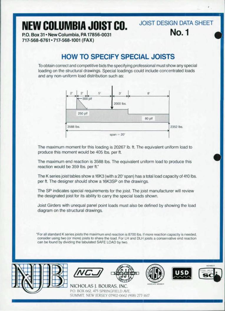
HOW TO SPECIFY SPECIAL JOISTS To obtain correct and competitive bids the specifying professional must show any special loading on the structural drawings. Special loadings could include concentrated loads and any non-uniform load distribution such as:
2' 2' J 5' 3' I 8'
SPlf 2000Ibs.
250 plf I 80 plf
3588lbs. 23521bs.
span = 20'
The maximum moment for this loading is 20267 lb. It. The equivalent uniform load to produce this moment would be 405 Ibs. per It.
The maximum end reaction is 3588 Ibs. The equivalent uniform load to produce this reaction would be 359 Ibs. per It:
The K series joist tables show a 16K3 (with a 20' span) has a total load capacity of 410 Ibs. per It. The designer should show a 16K3SP on the drawings.
The SP indicates special requirements for the joist. The joist manufacturer will review the designated joist for its ability to carry the special loads shown.
Joist Girders with unequal panel point loads must also be defined by showing the load diagram on the structural drawings.
'For all standard K senes joists the maximum end reaction is 8700 Ibs. If more reaction capacity is needed, consider using two lor more) joists to share the load. For LH and DLH joists a conservative end reaction can be found by dividing the tabulated SAFE LOAD by two.
!NCJ! NICHOLAS I. BOURAS, INC. PO. BOX 662. 475 SPRINGFIELD AV . SUMMIT. NEW JERSEY 07902-0662 19081 277- 1617

•
•
•
HISTAR® A new generation
of rolled beams and column shapes
for economical steel construction.
Once aga in, AABEO leads the Industry by featUri ng a trendsetting combination of mechanical, chemical and technolog ical properties'
DlIIIOVJd'ORI or ITDL CCWiiRUCTION PRODUCTI.
• HIGH YIELD STRENGTHS (up 10 65 KSI) even for ultra-heavy section.
• OUTSTANDING TOUGHNESS PROPERTIES
• EXTREMELY LOW CARBON eOUIVALENT - ensures elleel· lenl weidablllt)'
A NEW PAOCESS.~ OST.
The secret is In AABED's (8volu· tlonary new In-Une OST process
OTHER RECENT AlI.ED INNOVATIONS:
ARBED·ROlLEO .ao -, '4 -, and ·'TAILOR·MADE'· (WTM) ",le$ -famous 'or high tec:Uon moduli. gr •• , 'alera' buckling resistance, and big savlngl In fabrication costs and we6ghts. These products are allo available In the new HISTAR Quality as Is our standard WF •• rl •• and H SEARING PILES
NEW LITERATURE AVAILABLE
Send now for complet. data on , II ttlase AABED products, contact Trade "ABED, INC., 825 Third Ave., New York , NY 10022 (212) 486-9890, FAX 212-355-215912421 In Canada TradeARBEO Can.da Inc., 33<lO Malnway, Burlington, Ontario, Canada L7M 1A7 (416) 335-5710, FAX 41&.J35.1292

MODERN STEEL CONSTRUCTION
Volume 33, Number 5
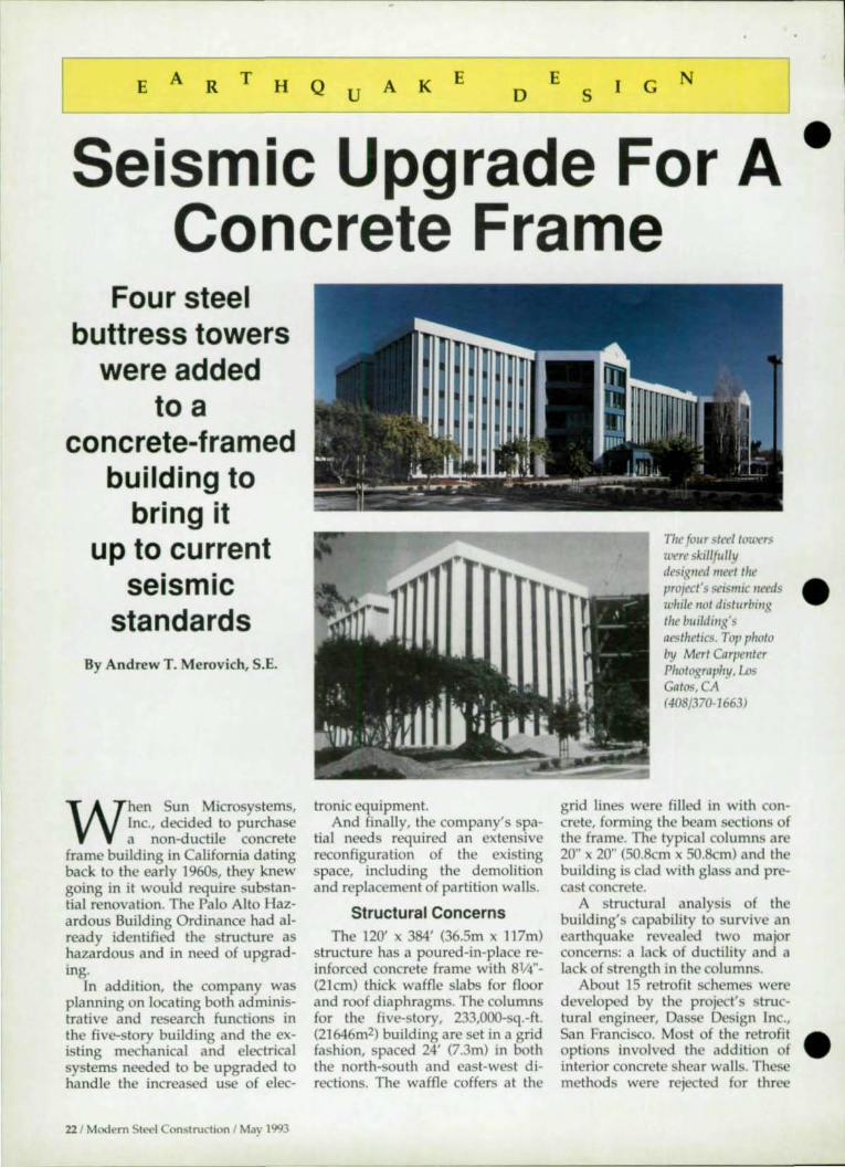
fou, steel buttress towers were added to tllis cmlcrete -framed structure;n order to bring it lip to Cllrrellt seismic stmldards. I t! addition ,
th, additioll added 26,()/J() sq. ft· of usabl, space. The story be11ind this il1novatit't reI/ova"OIl b"gills Oil page 22. Photo by Mert Corp""ter Photography, !.os Gatos, CA (408) 370-1663.
Modem Steel Construction (Volume 33, Number 5). ISSN 0026-8445 Published monthly by the Amencan Institute of Steel Construction, Inc. (AISC). One East Wacker Dr., Suite 3100, Chicago, IL 60601 -2001 .
AdvertISIng office: PaUis/3M, 7161 North CICero. Lincolnwood. It 60646.
Subscnpllon pnce: Within the U.S.-5lngle issues $3; 1 year
$30; 3 years $85 Oulsode the U.S.-smgle ISSueS $5; 1
year $36; 3 years $100.
Postmaster: Please send address changes to Modern Steel Construction, One East Wacker Or. , Sulle 3100, Chicago, It 60601-2001 .
Second-class postage paid at Chicago, It and at additonal mailing offices.
4 1 Modern Steel Construction I May 1993
May 1993
FEATURES 14 FABRICATORS, ENGINEERS
AIM FOR CONSENSUS Despite differences in views on allthority attd liability, ittdustry-wide agreement Ott desigtt responsibility is close to becomittg a reality
22 SEISMIC UPGRADE FOR A CONCRETE FRAME Four steel buttress towers were added to a concrete-framed building to bring it up to current seismic standards
28 ACTIVE BRACING SYSTEMS A recent filII-scale mockllp showed tlte practicality of "smart" bracillg systems for seismic desigtt
34 WEST COST QUAKES SEND TREMORS THROUGHOUT THE EAST /I used to be that ottly buildittg out West tteeded to meet strict seismic codes; blltltOW building codes alottg the Eastern seaboard have been drastically amended
NEWS AND DEPARTMENTS 6 EDlTORlAL 12 STEEL NEWS
• Steel Calendar 9 STEEL • New Computer
INTERCHANGE Program For Moment • Design of a bracket Rotation Curve
connection carrying moment 43 FASTE ERPRODUCTS
• Welding nuts to bolts to prevent backing off 50 STEEL MARKETPLACE
• Connecting wide-flange beams to tube columns
•
•
•

There are those who have seen the future.
Announcing the arrival of STAAD-III/ISDS - Release 17. Once again, Research Engineers, has made the technology of tomorrow available to you today.
Use newly introduced facilities like NON-LINEAR analysis , TIME HISTORY analysis, user-controlled multiple iteration P-Delta analysis , steel design for transmission towers (ASCE Pub. 52) etc. in addition to 14 different steel , concrete , and timber codes, to explore the widest possible range of design solutions.
Release 17's powerful printer plott ing capabilities allow you to generate the industry's sharpest and most comprehensive run output. For the first time, you can combine numerical output with graphical output - all in the same run document. Yes, we support the widest possible range of printers - from sophisticated lasers to down-to-earth dot- matrix printers.
On the graphics front , Release 17 features an enormously enhanced graphics input generator with
. aralleled speed and power, In addition,
Release 17 marks the debut of AutoSTAAD/MAX - the world's first integrated structural software system that works entirely within AutoCAD.
All these powerful capabilities coupled with the industry's most knowledgeable and experienced support staff, makes STM D-III/ISDS the ultimate productivity tool you've been waiting for.
STAAD-III/ISDS Release 17 - there are those who have seen the future ... have you?
.-.Research liliiii CC Engineers, Inc. 1570 N. Batavia, Orange, CA. 92667. CALL TOLL FREE (800) 367-7373 Tel : (714) 974-2500 FAX:(714) 974-4771
Research Engineers Worldwide U.S.A. • U.K . • JAPAN . GERMANY . FRANCE . NORWAY . CANADA . INDIA

Editorial Staff Scott Melnick,
E
Editor and Publisher Patrick M. Newman, P.E.,
Senior Technical Ad visor Charlie Carter,
Technical Ad visor
Editorial Offices Modem Steel Construction One East Wacker Dr. Suite 3100 Chicago, I L 60601-2001 (312) 670-5407
Advertising Sales Pallis-3M 7161 North Cicero Lincolnwood, lL 60646 (708) 679-11 00 FAX (708) 679-5926
AISC Officers Stephen E. Egger,
Chairman Frank B. Wylie, 1Il,
First Vice Chairman Robert E. Owen,
Second Vice Chairman Robert D. Freeland,
Treasurer Neil W. Zundel,
President David Ratterman,
Secretary & General Counsel Lewis Brunner,
Vice President, Membership Services
Geerhard Haaijer, Vice President, Technology & Research
Morris Caminer, Vice President, Fina nce / Administration
o
6 / Modern Sttocl Construction I May 1993
T o R A L
Pet Peeve #2 While computers and their ilk have simplified our daily
business activi ties-and cut costs-they've also added a lot of aggrava tion.
For example, we're always trying to keep Modern Steel Construction's ci rculation as up-to-date as possible. As such, we send readers renewal cards every year. When a reader hasn' t responded to a renewal card in a while, we send a "last chance" notifica tion. Unfortunately, our instructions to our computer system were not d ear enough, and letters went out to everyone with a stop date in February, whether they had renewed or not. My apologies to those I harangued unnecessa ril y.
But I know I'm not alone in Computer-Aided Failure. I' ve already mentioned my disHke for poorly conceived voice mail systems. Just as bad are Fax Abusers.
The latest example of fax abuse 10 cross my desk came in the form of
•
a press release from a huge, East Coast-based corporation. To start with, • there was no reason for the press release to be fa xed . It contained no information of shocking urgency-rather, it was a run-of-the-mill new product announcement. In fact, it wasn' t even a product related to the steel industry. Yet this company felt the need to tie up my fax machine with the equi valent of junk mail. Bu t to add insult to injury, they have not yet mastered the automated fa x technology they are using, and ind uded with my copy was a two-page Hsting of their maillist.
Customer service is another area where technology has all-to-often proven a failure. I recently purchased a piece of mail-order software that, unfortunately, came with a defective floppy disk. I called the company's customer service number, but of course it was busy. I called back. It was busy. I ca lled back and got through to a voice mail system. But when I tried to leave a message, I was informed that the system was " fulJ" and I should ca ll aga in. Which I did, with the sam e resul t. Finally I resorted to faxing them a note (which was not ea y in itself, since their fax machine was almo t continuously busy). To their cred it, however, I did receive a replacement disk in less than three weeks (though no other acknowledgement was sent).
The problem seems to be that the people who implement systems based on new technology never have to experience the frustrations of actually using the system. The solution, which few executives seem willing to implement, is to put yourself in the position of your customer. Not just on a theoretica l basis, but in practice. Call your company one day and see what an outsider goes through. Place an order. And finally, • sit down at a computer terminal and see what actually goe on with your inventory and order input system. SM

D
to. tfl to.
•
•
•
Our breakthrough 3-D technology can't De shown
in a 2-D ad.
Call for your first hand demonstration of the SDS/2
Detailing System.
Break through time-{;onsuming 2-D, line-by-Iine graphics with the 3-D technology of the SOS/ 2 Version 5.4 gives you the ability to automatically produce shop draWings and other information about a structure never before possible. The benefits are invaluable to design engineers, steel fabricators and detailers ... or anyone who is involved in the conception and production of steel.
The SDS/ 2 Software Solutions are the ultimate steel fabrication tool. All information created in SOS/ 2 or transferred through DesignLlNK from third-party design software, can be used throughout all phases of design and fabrication. The SDS/ 2 Software Solutions include:
• Engineering Analysis and Design Module • Detailing Module • Production Control Module • CNC Interface • F.mmating Module • DesignLINK Call Design Data to arrange your personal demonstration or to request
additional information.
DESIGN DATA "First in ... software, solutions, service" 402-476-8378 or 1-&>0-443-0782

•

•
•
•
Steel Interchange -------
Stetl hlttrchangt is an open forum for Mod"n Stetd ConstrllctWtl readers to exchange usefuJ and practical professional ideas and in· formation on aU phases of steel building and bridge construction Opinions and suggestions are welcome on any subJed covered in this magazme. If you have a question or problem that your fellow readers might help to solve, please forward it to Modrnr Steel COli · struction. At the same time feel free to respond to any of the questions thai you have read here. Please send them to:
Steel Interchange Modem Steel Construction
1 East Witcker Dr. Suite 3100
Chicago, IL 60601
The following responses to questions from previous Steel Interchange columns have been re
ceived:
Can you show a design of a bracket connection carrying moment (February 1993)?
One solution can be arrived at by visualizing that the beam and bracket act together as a single
unit. The problem now is similar to a haunched beamto-column connection which is a more familiar moment type connection. In order to design a rigid connection using the above assumption, an end plate can be utilized to which both the beam and bracket are fully welded. For the same reason, it is advantageous to weld the bottom flange of the beam to the top plate of the bracket rather than bolting them. This subassemblage can be fabricated in a shop with relative ease and efficiency. It can then be bolted the column in the field later.
The vertical web stiffener, defining the critical area of the web, will create a web panel with an aspect ratio between 0.75 and 1.50. This web panel should be able to resist moment Mo without excessive shear defonnation (no yielding or buckling). Otherwise, additional diagonal stiffeners will be required to carry the balance of flange tensile/compressive force via truss action.
The bracket sha II be designed for vertical forces, V m and V", applied at point A (Case I). The end plate should be proportioned to resist the same load, i.e. V m + V", in tension. However, prying of the column connection bolts may control the end plate thickness requirement. In situations where the connection between the bottom flange of the beam and the bracket top plate is rendered through bolts in bearing, the end plate shall provide resistance against a portion of the shear force acting between the two surfaces. This is in addition to the tensile forces mentioned earlier and tends to complicate the end plate design.
The column connection bolts shall resist the fixedend moment of the beam, Mf' and its end shear, VI' for the clear span between columns. Column flange stif-
Answers and / or questions should be typewritten and double spaced. Submittals that have been preparl'<i by word·processing are appreciated on computer diskette (either as a Wordperfect file or In ASCII format) .
The opinions expressed in Sled hrtercllaflge do not necessanly represent an official posi tion of the American Institute of Steel Construction, Inc. and have not been reviewed . It is recognized that the design of structures is within the scope and expertise of a compet('nllicensed structural engineer, architect or other licensed professional for the application of principles to a p.lrlicular structure.
Information on ordering AISC publications menttoned in thiS ar-ticle can be obtained by calling AI at 312/670-24ooe'(1. 433.
b
T
( "'I
c
P J .h_lc/ T • .!1L_ C
" V"'~ p. '11 ... '11 ...
,~~ 1 b
T
V;
f)'" -. 11 c
1
CASE I[
feners sha II be provided similar to any other bolted connections.
If the flange area of the gusset plate is within the same order of magnitude of the beam flange area, it is preferable to use the same width for both nanges and eliminate the bracket top plate (Case II).
Abbas POllrbohloll1 Consolidated Rail Corporation Philadelphia, PA
Modern Steel onstruction 1 May 1993/9

---- -- -------------------------------------------------------------
Steel Interchange
Is it permissible to weld nuts to bolts to prevent then from backing off? Are any special welding proceduIes requued? Is bolt or nut slIength affected?
While it is not considered desirable to weld a nut to a bolt, it is not uncommon to encounter
situations where loosening of nut could pose a real threat for slIuctural failure. In a recent case involving
...
---~~~ .. ..-
the base of a tall tower, the undersigned was faced with a similar situation where the columns were su bjected to mild but continuous vibrations and loosening of the nuts had to be prevented. This was accomplished by tack welding retainer bars to the column base plate adja-cent to each of
the two achor bolts as shown in the figm e. This was done because the anchor bolts did not have sufficient projection for a second (locking) nut.
Vijay P. Kitnsal , P.E. Ohio Edison AIaon, OH
How can you connect wide-flange beams to tube columns?
The figure below shows a different concept of connecting wide-flange beams to all fom faces of a
slIuctural tube column to transfer moment and shear than has previously been offered in Steeiintercitallge. The end stiffener plates, connection plates and other connection material can be shop welded and the beam can then be bolted to the column in the field.
George Chiang, P.E. The Port Authority of NY and NJ New York
'1 I,
~ 1 I
I
I
- .
_~,J d.ff ~ (Tft.)
CDnNtf,.;, rl ( T ..I ~ )
=.--- ---~ .:;.
-" i 1. _ CfJQlin f,;,. Ii ,- r.! 8)
, II '
I" Il.t
CDII",·,:f/ ~' 0 I,/~
: \" .. ". JM! tl ·
New Questions
Listed at right are questions that we would like the readers to answer or discuss. If you have an answer or suggestion please send
it to the Steel Interchange Editor, Modem Steel Construction, One East Wacker Dr" Suite 3100, Chicago, 1L 60601-200l.
Questions and responses will be printed in future editions of Steel Interchange, Also, if you have a question or problem that readers might help solve, send these to the Steel Interchange Editor,
10 I Modern Steel Construction I May 1993
Under what circumstances does the designer have to consider torsion in the design of a
beam?
A re there any design aids that will help an engineer design a steel a_rch or a communications
tower?
H ow can One take into account blast effects in the design of steel structures?
•
•
•

•
•
•
TOOLS FOR STRUCTURAL ANALYSIS AND DESIGN
• EASE OF USE • SIMPLE DESIGN PROCESS • SPEED AND ACCURACY • UNIFIED WORK ENVIRONMENT.
TEST DRIVE SOFTWARE THAT WORKS AS GOOD AS" LOOKS! TO SEE WHAT THE EXCITEMENT IS ALL ABOUT,
VIS" OUR BOOTH AT THE A/E/C SYSTEM '93 IN ANAHEIM.
FAST AND POWERFUL • easy modeling of simple fromes and
powerfvl tools for large and complex structures
• high speed, leaves competi~an behind: 3D roof, 735 nocIes, 4 load cases, 2901 beams, 4296 DOf, computed in 2'27" on a notebook Toshiba T 4400
metrosofi 332 Palenoll ill'e
Ea,1 RLII"er!tmJ. NJ 0707 J
UNEQUALLED INTEGRATION • in linear stotic, dynamic, seismic, non
linear, buckling • for beams, plates, shells, cables
• in 20 and 3D • for steel and concrete clesign • on PC compo~bIe computers • universol network solution (NetWare,
lontos~c and all NetBlOS compo~bles)
COMPREHENSIVE AND INTUITIVE • easy to use even for the new or
occasional user • user friendly: menu driven, gUIded logic,
instent eccess to all resources, rapid Hyper1ext help system, integrated macros
• all input data and results can be processed in text or In Ivllgraphic mocIe (loading, boundary cortditions, materials,..)
• interfoces with most CAD softwcre (DXF, HPGl, IGES)
DEMO AVAILABLE (LIMITED VERSION OF PROGRAM WITH SELF-RUNNING EXAMPLES) OVER 1200 USERS WORLDWIOE. fOR MORE INFORMATION CAll 201-438-4915 OR FAX TO 201-438-7058

S T E E L C A L E N D A R
AISC Lecture Series : New Ideas In Structural Steel
A ISC Marketing, lnc. is now presenting a new lecture se
ries focusing on innovations in structural steel design. NI!W Ideas In Strllctllral Steel wiIl present practical design concepts for engineers and fabricators.
WEST Date
Los Angeles 514
Irvine 6/10
Sacramento 6122
San Francisco 6/24
SOUTHWEST Date
Dallas 516
San Antonio 6/1
Houston 6/8
11th Annual Construction Law Seminar (May 7 in Chicago) sponsored jointly by Chicago-Kent College of Law and the Con· structian Law Institute. Workshop highlights include: "Shifting from the Private
Sector to Public Sector Projects" (the session
wiJI focus on the new Capital Development Board Service Agreement and Construction
Agreement); .. Are Your Lawyers Making Vou Crazy" (a panel discussion o f ways to
control lcga l costs while also improving the quality of legal service); "Project by Project Insurance" (workshop will offer practical
guidelines to help construction profession.
als identify the kind of coverage they need, such as owner· funded project insurance, wrap--ups. OCP policy, and coverage for pollution or hazardous materials); "The Mentor {Protege Program" (offering infor·
mation on affinnative action requirements);
and "The Americans with Disabilities Act" . For more information.. contact: Bruce J. Schulte. Chicag<rKent College of Law, 565
Wesl Adams 51., Chicago, lL 60661-3691 (312) 906-5250; (ax (312) 906-5363.
Symposium on Project Management (May 13--14 in Chicago) sponsored by Association for Project Managers in the Design Profes·
12 1 Modern Steel Construction I May 1993
The four-part seminar covers: • Low-rise buildings. • Design of connections. • Eccentric braced frames. • Partially restrained connections.
Registration fee is $60 ($45 for AISC members). Included in the
MIDWEST Dote
Detroit 5111
Indianapolis 5113
Minneapolis 5125
Mitwaukee 5127
Chicago 6/3
SOUTH Dote
Birmingham 9/9
Miami 9/14
Orlando 9/16
Atlanta 928
Richmond 9130
sions. Topics indude: sta te of the art proj«:t
management techniques; the emerging con· rept of partnering; creating a Total Quality
Managemen t component to each design project; making effective project decisioruo;
new project management directions for the
economy of the '90s; and case studies in·
eluding managing quality on the new Inter·
national Complex at O'Hare Airport. Con· lact: APM 01 (312) 472-1777; Fax (312)
525-0444.
Lasers in Fabricating Conference (May 18·
20 in Schaumburg, fL) sponsored by the Fabricators &: Manufacturers Association.
TopiCS include: equipment selection and cost justifica tio n; precision laser cutting
techniques; VAG, fiber..<felivered processing; laser/ punch combination machines.
high..energy thermal processing; program· ming laser cutting systems; COl multiaxis processing; material handling equipment;
equipment specifications; maintenance; and safety. For more information, call (815) 227·
8202.
registration fee are a dozen handouts and publications plus a meal. For information, contact: Colleen Hays, AlSC, Inc., One East Wacker Dr., Suite 3100, Chicago, fL 60601-2001 (312) 670-2400.
NORTHEAST Date
Newark 6/22 Rochestor 9122
Albany 9123
MID-ATLANTIC Dote
Baltimore 5118
Washington 5120
Philadelphia 6/23
Cleveland 10/19
Cincinnati 10121
Structural Engineers Associa tion of South·
em California Computer Show aune 7·10 in Anaheim, CA) held in conjunction with
A{ E/ C Systems '93. Seminar series tar· geted at practicing structu ral engineers. Sessions include: practical aspects of dynamic
analysis using standard finite element anal·
ysis software; benefits of marketing an aut<r mated structural engineering office; and spreadsheet software. For more infonna·
tion, contact: SEAOSC, 2550 Beverly Blvd., Los Angeles, CA 90057 (213) 385-4424; (ax
(213) 389-7514.
1993 Symposium on Computer Integrated Building Sciences Oune 1()"11 in Anaheim,
CA) sponsored by the Interna tional Council
for Building Research and Documentation. Topics will include: automated construc· tion (using no people); automated fabrication; robotic tools fo r construction; and 3D
modeling. An additional session will fea· tore the new Disney Concert Hall Project,
w hich has been designed on 3D CAD and has used NC for the cutting of stone and structural steel. For more information, con
tact: Harold Jones, SClBS'93, 1700 Asp Ave. nue, Norman, OK 73037-0001 (405) 3~ 1947; Fax: (405) 3~7968.
•
•
•

•
•
•
STEEL NEWS ----
Finding Moment Rotation Curves One drawback to designing
partially restrained connections has been finding a reliable source of moment rotation curves. That problem has been relieved, however, by a new computer program from RMR Design Group, Inc. called PRCO N. As its name indicates, the program is designed specifica lly for generating moment rotation curves for partially retrained connections.
The program, which runs on IBM-«>mpatible personal computers with MS-DOS, offers 31 connection options, including: top and seat angle; single web angle; double web angle; header plate; single plate; and welded double web angle. All of the former also can be specified with top and seat connections. The program also allows the use of any of the connection options in a composite connection. The connection library also includes the option of bolting or welding and constant or variable Iiiiiiii load beam lines giving beam end I • moments and rotations. Also, it offers uniform and concentrated load options with midspan deflections.
The experimental data used for PRCO development and verification were obtained from tests reported in archival journals, conference proceedings, and university theses and reports.
The program "builds" a given connection based on the strength and force-deformation properties of connector elements that are typically 3" in length. Connector elements are bolted or welded single and double angles and bolts in single or double shear. Connector strength and force-deformation properties in tension, compression, and hear were obtained from laboratory tests.
The output includes all inputted material and configuration information along with deflection and moment-rotation curves and beamlines.
For more information or a free manual, contact: RMR Design Group, Inc., 4421 E. Coronado Dr., Tucson, AZ 85718 (602) 621-8251.
"-ICl.. I: CCW'05ITE. 5Uc.lE I"lRT( CIH£CT ION
12'10
~ , 991 L • i "" I ...
"'.
(1:'"'1" 17 MAP'! WfJ' 18.00 MFfII 'fIELD STI'I(~TH "511 . 50.00 Sl Mlft'RO...l.6TOT liN)_ .00 j:N).[I I'lRl£ THICIU€SS liN! .. . le STEEl rJIIU: "511· 16 . DO .. 80..15 - OIMTE" IINl - 1I"
tOt:NT-fllDTATI(III ClIW£
· . · . · . ' .. . : ~ : .. .. ~ " .' " ~ .' .' ~~ .' .~ ,
10
791-2011
,.,. . - 5((1 ff'l(R U .... Zh 2.00 DI5'''<[.''' - I'I[8Rf11 i1N1. 2.DO 1Il. ' 'TI'{ 1Al2S I j:N901.. R.l2S .RM 1«11 l HIOIfiI[ SS IINl · .50 JlrrG.[ III ftLAT[ CK,( IINl. .00
lUCiTH til IIlIt1 IrYl - 32. 00 BERM INl"'TlR liN .... ' -1&00 .00 ~I' ''' lCR) MIl-1FT). 2 . 00
"ICfAiC C\I'IIt[ ~'["'l " .. 1t.7I11(°05 It'" ] . 56J(j( oOZ flO- 1. ]J5,2[ ·03 N • 1.10
11["" lift: fl:U lSI 01 ". 6 . _ , • I S. l . N I o "I"'h. .,,12 o "If\e • . lj68 • "I", la . . JOe • "1"- . . 692
"10-,.,., DEFlECI I""" IIIG. .6'13 eE ~ Y"t:W I l60 II HI • 1. 061

Fabricators, Engineers Aim For Consensus
Despite differences in views on authority and liability, industry-wide agreement on design responsibility is
close to becoming a reality
N early 300 structural engineers and fabricators listened raptly to arguments over who has the ultimate responsibility-and liability-for de
signs at a special session immediately preceding the start of this year's ational Steel Construction Conference on March 17. Although few-if any-minds were completely swayed even after 12 speakers and nearly four hours, participants did appear to be moving closer together.
""ve been fighting this battle since 1984. I want to try to look for more solutions instead of going over the old arguments," stated Richard Tomasetti, P.E., principal, Thornton & Tomasetti Engineers, New
Richard Tomasetti, P.E. York City, a structural engi-neer advocating
shared responsibility. Tomasetti's position, in a nutshell, is that if the fabricator is only doing detailing, then he need not take any responsibility or liability for the connection design. But if the fabricator's services extend to design, then his responsibility also extends to that design.
"I want to change the question [from who is responsible for design] to who is responsible for the services a given party provides," he stated.
Leonard Ross, president, L. . Ross Engineering Co., Atlanta, and former president of the ational Institute of Detailing, countered Tomasetti 's argument by citing O.B. Steinman's remarks that there must be a clear-cut demarcation between engineers and non-engineers. "Let's be wise enough to prevent some of the future mishaps by rejecting attempts to improperly and unlawfully shift responsibility from the design professional to another party," Ross added. "A P.E. is licensed to perform and protect the public from harm.
14 1 Modern Steel Construction I May 1993
The engineer of record is the captain of the ship and cannot and must not abrogate any responsibility for the safety of his ship."
While the question of design responsibility has simmered for more than a decade, it came to a boil in 1991 with the is-
Leomard Ross, P.E.
suance of the "Fernandez Memorandum." According to the memorandum, issued by Henry A. Fernandez, deputy commissioner of the professions for the ew York Education Department, " ... the practice of delegating design responsibility to unauthorized firms constitutes unprofessional conduct under the Rules of the Board of Regents and New York State Education Law." Among these unauthorized firms are construction contractors, such as steel fabricators. (See accompanying story for more on this subject.)
James Stori, president of AISC-member STS Steel, Inc., Schenectady,
Y, began Ius presentation by reminding the audience that the Fernandez Memorandum did not change the rules; rather, its purpose was to remind engineers of the a 1-ready estab-lished ru les.
James Stori
Unfortunately, there has been increasing pressure
•
•
•

•
•
•
from the design community to alter these rules.
Among the reasons for the desire to shift responsibility are: pressure from lawyers and insurance companies; increased project complexity; a reduction in the quality of structural drawings produced by fabricators; and tighter budgets and time frames for project completion. As a result , Stori explained, many engineers have deleted the word "approved" from their review of shop draWings. Also, engineers are increasingly requiring fabricators to submit calculations on drawings and to have a P.E. among their fabrication staff.
"I like to think of engineers and fabricators as partners," Stori stated. The fabricators know what it takes to put a building together in the field- what is safe and practical, while the engineer of record has more theoretical knowledge. The fabricator has seen a wide range of details from a variety of engineers, while the EOR only has access to his firm's work. However, the fabricator does not have access to all of the design information for a given project. In the long run, it is the engineer of record who has his name and reputation on the line, according to Stori.
Rather than delegating responSibility, Stori believes the EOR must insist on quality. "lIe can require submission of details ahead of time," Stori opined. "He can require a P.E. in supervision of the detailing and connection selection process. He can stipulate drawing turnover times so that he's not rushed and he can also stipulate AlSC certification [for the fabricatorI or its equivalent."
However, not all fabricators agree that the sole responsibility for design rests with the engineer of record.
"The present code requires the engineer to accept responsibility for hundreds, sometimes thousands of connections that he sees for the first time one day and then, two weeks later, he must return them approved or approved a noted," according to Sophus Thompson, president, AISC-membcr Austin Steel Co., Inc., Dallas. "These are drawings that we as a fabricator have worked on for weeks and weeks. We've designed them, we've drawn them, and we've checked them. It is our feeling it is impractical for the engineer to be fully respon ible for all of the connections shown on the shop drawings given the time pressure that is associated with the approval project on every project." He favors a clear division of responsibility, where the fabricator would be responSible for three types of connections: • Where the shear, axial load, and moments are
shown on the design drawings;
The Fernandez Memorandum
I ts st,)ted subject, "Unlawful Delegation Of DI.'Sign Rl'Spon~ibility By Design Professionals," says it all. In August of
1991, Ilenry A. Fernandez, a deputy commissioner for the ew York State Education Department, sent shock waves
through the design and construction community. The memo states, unequivocally, that ultimate design re
sponsibility rests with the engineer of record. "In rl'Cent yeaT';, however, there has been a trend to shift responsibility for final approval of the "shop drawing" to persons other than the principal design professionals," Fernandez wrote. "Frequently, general construction contracts for buildings contain language pertaining to written specifications that have been interpreted to require unlicensed persons, such as subcontractors to provide professional design services. In other cases these contracts require the work to be performed by a licensee, as either an employee or consultant to the subcontractor. The end result is that the completed structure has parts designed by several parties, with an absence of responsibility on the part of the principal design firm or firms to ensure that the entire structure will function properly and safely as an integrated system. The purpose of this memorandum is to inform and remind alllicensed design professionals that the practice of delegating design responsibility to unauthorized firms constitutes unprofes- Robert Rubin, P.E sional conduct under the Rules of the oo.1rd of Regents and ew York State Education Law."
Robert A. Rubin, counsel for the American Society of ivil Engineers and a licensed engineer himself, brought suit to d clare the memorandum null and void. Rubin's argument, essentially, is that Fernandez miSinterpreted New York law and was not merely reminding the engineering profession of an existing regulation but instead was creating a new rule.
The lawsuit was recently dismissed in part because "Since the Memorandum is neither a rule or a regulation, It has no legal effec!." Also, since no attempt has been made to enforce the Memorandum, there is no legal dispute on which to base a lawsuit.
However, the battle is not over. Rubin has appealed the decision to the Appellate level and expects a ruling 1111994 'The problem is that the piece of paper is still there," Rubin stated
~uring the Design ResponSibility session at thIS year's a
tiona I Steel Construction Conferen e. By appealing, Rubll1 hopes to force the State Education Department to deal With the issue directly and issue niles that will supersede the memo. J
Modem Sh.o.el onstru lion I Ma,· 1 ~1 / 1S

Sophus Thompson
• For shear connections of beams, where the shear force is not shown on the design drawings, but where the reaction can be calculated from AISC tables.
• For moment connections where full
PA and a represen ta ti ve from the Coalition of American Structural Engineers (CASE), the fabricator may be choosing a connection from an A1SC source but is not actually designing it. "We retain responsibility," he stated .
Abraham J. Rokach, P.E.,
D. Kirk Harman, P.E.
moment capacity of the member is indicated on the design drawings.
The engineer would be responsible for all other connections.
"Allow the fabricator to design connections that fit his expertise," Thompson stated . "Put the work with the corresponding responSibility or liability where it fi ts naturally."
Not everyone agrees with Thompson's interpretation, however. According to D. Kirk Harman, P. E., a principal with Cagley and Harman, King of Prussia,
A1SC senior staff engineer, spent several minutes naming various A1SC sources, and the list was impressive. The list included: Volume II Connections; LRFD and ASD Manuals of Steel Construction; LRFD and ASD Design of Simple Shear Connections; ASD and LRFD Specification for Structural Joints using ASTM A325 or A490 Bolts; A1SC Design Guides; the CONXPRT computer program; and Engineering Journal. "It's wrong for professional people to try to reduce their responSibility," Rokach stated . He then compared the medical and engineering professions,
Celebrating Our 2nd Decade of Seroice! SCADA The state-of-the-art
Structural Engineering System
The SCA DA "itructu ra! e ngineering soft ware syste m rcprc~cn" an integrated design·anal).., is
'\ ____ ..;\ e nvironment. It includes complete re inforced concre te a nd Mccl design capabili ties. The design procedures arc closely co upled to the SCADA analysis "," ' hods. SCADA includes an efficient J· D fini te c leme nt structural analys i.., module with a large c leme nt library a nd a wide range of a nalysis capabi liti es. It offe rs the choice of three preprocess ing
,~ __ ---~~ model definition procedures· spreadsheet !<I t) Ie. drafting M) Ie and adva nced geome tric and
\olid modeling style . The SCADA display ca pabil i'ics a rc powerful and
---____ cfficicnt . incl uding ..,haded image. continuous ~ _______ -, color contour
and line con to ur plott ing.
For m/umullfon l"onUk l
Ca/>abiliti es: . S ta t ic ..
. D)na m ic- ... T imc Hi~ hlq Dl namic:,· Rc .. r o n .. e Spcc trum
• P. Dcl l li
. Uuckin j.:
. No nlinea r Stali n .lnd O ) n;ll11i c!t Geo metri c and Mat e ri a l Nonlinearity
. Com plctc Elcmt' nt Libraq Truss, Beam , Kirc hllll H Plate , S hear Pla te, Plane S trcs~ , PLane t rai n . A .. is)mmc lri c, he ll. Solid
. 5'1'('1 and Concrete DC!t iJ: "
. CAD T ransl.ll o r ..
. Ccome tri c a nd Solid Model in g
. M c!th Gc nl' r.lIi u n
. SQL Re latio nal Dat llba sl' Hc po rtin g
SCADA -;oftwJ rl Corporation 1202 1 W.I .. h,rc RI\'~I .. Suite 676 L: .... Angdc ... CA QOOli Tel (lI OI176· II<\O F." , (l 10) 176.1141 ~~CL ______ ...J
•

cO
•
•
•
Richard Homer
which both are experiencing rising insurance costs. "There are the same problems, but doctors take additional, not less, responsibility."
Added Harman, "Over th years, we have found that there is still a significant amount of risk for the
structural engineer even if we delegate the connection responsibility. If there's a connection failure, we all will be sitting at the table-the architect, the structural engineer, the contractor, the fabricator, and probably anybody else who walked by the site during construction. Why don't we just solve the problem now and avoid all of that time and effort."
Part of the question revolves around insurance. Richard Homer, with the Victor O. Schinnerer & Co., Inc., a leading insurer of architects and engineers, noted that his firm has not pushed the shop drawing
issue with their clients. He did add, however, that most engineering in urance policies contain an exclusion where the engineer manufactures a building component. Mike Holcomb, with C A lnsurance, a leading in-surer of fabrica- Mike Holcomb tors, stated that most fabricators carry a general liability policy that does not cover professional liability. What that means is that most fabricators are not covered for preparing designs or plans. However, he added, at least one insurance company is currently working on a new pr<>gram that would offer professional liability coverage to fabricators.
Building owners add another dimension to the question and some have specific guidelines. As with the New York Education Department, the military clearly states that the EOR has the ultimate design re-
Production Control Get unrivaled control over every piece in your shop, every step of the way
I ~'I .. c...t.N1 '''-'''' ......
How would you like to be able to punch a fow keys on your comput8t and get instant, detailed tracking reports on the status of Individual pieces or entire jobs In your shop? Thafs exactly what Sfructural Software's new Production Control Tracking System can do for you. Shipping tickets, loading reports and olhe< status reports show what shop stations a piece passed through on what date. who did the work, how many manhours the work took and whaf still needs to be done to that piece. Bar graphs. like the one shown, give the number and percentage 01 comP'etion on any piece mark. sequence or job. The new traclOng system gIVes you the POW8f to see exactly what shopwork remains to finish a given piece marl<, sequence or job. Sorted fists show individual piece weights, assembly weights, even weighf of an steel on a drawing. Production Control interfaces with our Purchase Orders program to gefl8fate cutting Hsts that give you the addled capability of tracking material from the time ~'s ordered to the time it's cut The cutt>ng ists show shop employees exactiywhich pieces to pull, which pieces k> cut from themand which pieces to scraporretum k> Inventory. ProdUC1ion Control also works with our new Combining program to optimize your material cutting for evon more savings .
For a free demo disk, call Structural Software today at (800) 776-9118
.,-.- .- .-..----.
I PO 80K 1i220.~I"dI. .. Vd401i
Modern t('t.'1 onstructlon I May lC)q3/ 17

Survey of Building Code Officials
1. Are you aware of the issue of "shared design responsibility" with regard to the design of structural steel connections?
Dilly 20% of the respo"de"ts were aware of the isslle IJy lIame. 46% of buildillg officials were aware of the practice of shared respollsibility,
2. Under the current code in Y OUI jurisdiction, do you require steel connections to be designed on the construction documents p rior to your approva l?
50% of participallts do require cOllllectioll desigll prior to approval. Of this 50%, 22% illdicated that COIIditional permits, partial releases, or complete waivers are sometimes applied. 17% of the participall ts illdicated that no structural rel.1iew is performed at all.
3. Does the current code addIess the issue of
Rebecca Burleson
present time in your area? 100% responded "no".
shared responsibility specifically?
12% of ti,e participants believed that their code directly addressed shared responsibility.
4. Are there any revisions regarding shared responsibility being PUI-
sued at the
5. Does your code now allow the engineer of record to delegate the responsibility for steel connection design to the fabricator or contractor?
60% respollded "Yes." (Many of these-36%-added "but the "'gilleer is IIltimately responsible for the work dOlle on his/her design.)
6. If the EOR requires the contractor (or fabricator) to employ a licensed professional to prepare and stamp shop drawings for later review by the EOR, has the EOR shifted any of his/her responsibility to the contractor's engineer?
26%-Yes, responsibility rests with the seal all the desigll .
50%-No, IIltimately the "'gineer of record mllst be respo"sible for the acceptability of the elltire system.
24%- The courts wil/have to decide.
18 1 Modern Stet'l Construction I May 1993
sponsibility, according to Charles Gutber-let, Jr., a stnlC- • tural engineer with the U.s. Army Corps of Engineers. "Design responsibility remains wIth the Corp of Engineer designer. Transfer is not permitted." Sim-ple connec-tions-- those Abraham Rokach, P.E. found in the AlSC Manual of Steel Construction-are not required to be on drawings. Also, all fabricators working on Corp projects must be AlSC certified.
In contrast, Peter Schultz, a vice president with Lehrer McGovern Bovis N.j. in Princeton, NJ, believes that "fabricators must be responsible for theiI work." However, he a [so stated that both • engineers and fabricators need to be more complete in their drawings. One problem he Charles Gutberlet, Jr. noted is the lack of experience of the engineers doing the actual review of shop drawings. Typically, he explained, they are less experienced engineers. "There's a need for additional training programs in this industry," he coneluded.
There's also a need for a nationa l consensus, accord ing to Harman. Engineers who do not assign design responsibility to their fabricators are at a disad\antage since their costs will be higher. "There needs to be a level playing field," he ex- Peter Schultz •

• plained.
Currently, there is little agreement on where design responsibility rests. Rebecca Burleson, a professor at Auburn University, recently conducted a survey of building offidals and their reaction to the question of design responSibility. While 60% of the respondents indicated that the engineer of record could delegate connection design responsibility, nearly a third of those officials indicated that "ultimately the engineer is responsible for the work
Pictured at the podium: David Ratterman
Top row: D. Kirk Harman; Richard Homer; Richard Tomasetti; Robert Rubin; Charles Gutberlet, Jr.; Abraham Rokach
Bottom Row: Mike Holcomb; Peter Schultz; Rebecca Burleson; James Stori; Sophus Thompson; Leonard Ross
done on his / her design." Interestingly, while all of the 138 surveyed building code officials were invited to the design responsibility session at the NSCC, none showed up. "The codes do not deal with this topiC [design responsibility!:' Burleson explained. "It's open to the interpretation of the code official." But ultimately, she hoped, the solution would come from within the design and fabrication industry.
Towards this end, a two-day session, "Critica l Is-
sues In Design Liability: Emerging Risks And Liability In The Shop Drawing And Submittal Process" will be held by the Georgia Institute of Technology in Atlanta on September 30 and October 1. For more information, contact: Saeid Sadri, College of Architecture, Georgia 30332-0155 (404) 894-4875.
(To pure/lase a copy of a complete transcipt of tile four-hour session, contact: AISC at (312) 670-2400.)
TO DETAIL Computer Detailing Systems, Inc. introduces a state or the art structural steel detailing system II hich allows rabricators and detailers 10 meet the demands or the ruture with the ability 10 generate connection calculations, download to C:'lC equipment and interrace lIith major design firms through the Steel Detailing Neutral File.
A practlcal. flexible system requiring minimal training, COS is capable or producing illlclligcllI 3D models. Ooor plans and e1elations as lIell as shop drawings or unsurpassed qualit) using )'our standards and paper.
COS is cUITent11" used by Fabricators and det:ulers throughout the ~S 'lild in Canada.
(30NTACT COMPUTER DETAILING SYSTEMS /oday fOR A FREE INfORMATION PACK .
CDS ~ .... Slrll clll"I/ Sle ('/lJel(lIflllg ,\)'sle/ll
Computer Detailing Systems, Inc .• 7280 Pepperdam Avenue· Charleston, South Carolino 29418 • (803)552-7055

"Down the road, weathering ste~ .
The Pennsylvania ' Iurnpike is considered onc of the safest and beSt maintained roads in the nation.
But improvemcnts were badly needed ncar Pittsburgh to provide bener access to the city's airport and 1-80.
The ~ lahoning River Bridge, the largest of the 21 bridges being built on the new Beaver Valley Expressway, is a dual-lane, conrinuousspan, welded plate structure. The five interior spans are 258 ft with end spans of 182 ft and 228 ft for an overall length of 1,700 ft.
WilY \\,EATIIERING STEEL?
The bridge is built" ith -l,600 tons of Bethlehem's AST~I A588 weathering steel. According to Kempf, the PTe finds weathcring steel a very cost-effective bridge material for a number of reasons.
For example, its high strength permits longer spans, thus reducing the number of picn. required. And that leads to foundation COSt savings.
OTIIER STRONG REASONS.
For anothcr, it can be ea.ily inspected, measured and evaluated. If nccc"a,)', it can Ix: readily repaired. It's also highly adaptable to redecking, widening and performing other structural modification,.
Weathering steel also eliminate, the nced for both initial and maintenance painting. What's more, it's as attractive as it's environmenmlly sound.
Kempf comments, "Thc PTe', principal crite-ria for selecting material~ for bridges and other • Turnpikc applications aren't based on price alone but also include long-tcrm serviceability and durability. And with environmental restrictions being what they are today, it 's only prudent to '''e

• th " save us more an money. Frank J. Kempf. Jr .. P.E. Bridge Engineer. Pennsylvania 'Turnpike Commission.
weathering steci wherever possible." Quite simply, weathering steel is a natural for a
broad variety of bridge applications.
Including yours. Especially if you want to
save more than money.
TECIINICAL LITERATURE AVAILABLE.
We would like to tell you more about weath· ering steel for bridge applications. For a copy of our Product Booklet 0io.3790, and our latest lcchnical Bulletin, TB·307 on "Uncoated \Vcadlcring [CeJ SCfUCWfCS," get in touch with your nearest Bethlehem sales office. Or call: Brian Walker at (2 15)694·5906. Bethlehem Steel
ecorporarion, Construction t\1arkccing Division, Bethlehem,PA 18016·7699.
Owner: Pcnns)huniB Tumpil.;c Commission, Ilurnsburg, I)A Fllbricutor. Il igh Steel SlruCtun.«e, Inc .. LanclIstcr. rA Wcuthcrirtg Steel Supplier: Bethlehem Steel Corpon.I .... m. Ikthlehclll , I'A
Bethlehem 00
E A R T G H E E N Q A K u D I s
Seismic Upgrade For A Concrete Frame
• Four steel
buttress towers were added
to a concrete-framed
building to bring it
up to current seismic
standards By AndIew T. Merovich, S.E.
When Sun Microsystems, Inc., decided to purchase a non-ductile concrete
frame building in California dating back to the early 196Os, they knew going in it would require substantial renovation. The Palo Alto Hazardous Building Ordinance had already identified the structure as hazardous and in need of upgrading.
In addition, the company was planning on locating both administrative and research functions in the five-story building and the existing mechanical and electrical systems needed to be upgraded to hand le the increased use of elec-
22 1 Modern Steel Construction I May 1993
tronic equipment. And finally, the company's spa
tial needs requiIed an extensive reconfiguration of the existing space, including the demolition and replacement of partition walls.
Structural Concerns The 120' x 384' (36.5m x 117m)
structure has a poured-in-place reinforced concrete frame with 8V4"(21cm) thick waffle slabs for floor and roof diaphragms. The columns for the five-story, 233,OOO-sq.-ft. (21646m2) building are set in a grid fashion, spaced 24' (7.3m) in both the north-south and east-west directions. The waffle coffers at the
Tire four sleel lowers were skillfully desI81led meet tile project's seismic 1Ieeds • while IIot disturbi"g Ih, bui/dillg's aeslhelics. Tal' pholo by Merl Carpellier Pholography, Los Galos,CA (408/370-1663)
grid lines were filled in with concrete, forming the beam sections of the frame. The typical columns arc 20" x 20" (SO.8cm x SO.8cm) and the building is clad with glass and precast concrete.
A structural ana lysis of the building's capability to survive an earthquake revealed two major concerns: a lack of ductility and a lack of strength in the columns.
About 15 retrofit schemes were developed by the project's structural engineer, Dasse Design Inc., San Francisco. Most of the retrofit • options involved the addition of interior concrete shear walls. These methods were rejected for three

•
•
•
reasons: high co t; lengthy construction time; and an overall negative impact on building functionality.
The alternate to interior shear walls was to reinforce the structure using exterior buttresses. Various schemes-using both steel and concrete and either four or eight towers-were considered before the decision was made to add four braced steel towers.
10% Increase In Usable Space Analysis showed that four tow
ers were the minimum number requi red to brace the existing buildings. But more importantly, grouping the exterior braces into just four towers allowed the space within the towers to be useable, which added approximately 26,000 sq. ft. (2415m2) to the building. Unfortunately, this addition violated Palo Alto's recently established SO' (15.2m) height limit for occupiable space. However, since it fell within the allowable O.SO allowable floor /a rea ratio (FAR) and would substantially increase the seismic safety of the structure, the city council accepted the proposed deSign. The computer analYSis was performed using the ET ABS program from Computers & Structures/ Inc.
Steel braced frames were chosen over concrete systems because of their light weight, ease of erection, rigidity, ductility, and flexibility for window placement.
Architects on the project were Matarazzi Associates and Williams & Tanaka, both of San Francisco. General contractor was Koll Construction, San Jose, CA. The steel detailer and erector was A1SCmember Reno Iron Works Co., Inc.
Tieing It All Together Sub tantial ties, or collectors,
were provided to connect the existing structure to the new buttress towers. Steel plates, welded to the buttresses, were anchor-bolted to the concrete floor and roof beams, reaching into the center of the building. In addition, steel plates were added to strengthen the existing diaphragms at the roof and diagonal steel bracings were added
- -®e®@iS ® 0 ® ®~,® (!) Gl CD ® Gl <D 0 I
I >~ I ~~:I ;F~' ~ r -'V~ r- ~~ .• I ~l"_&-'..-...\ ~1'"
-,
®+--- '.1' 1 ~ I
<9 - ;
1 I ~>I_~, ........ _""" .. - i'- _ "@,...''''''' l .... _ "'. ot I I '" I " '" I 1
• %,1 Il\" . ·i. I
~ .: It oil}. ~ L--. ,,-,
~~I E!YC ~ ~ y ~ \. '" / . - -"-®
I
1 I < • KEY PLAN
- ------ -- J
TOWER PLAN J 1.0:1 "'" 1 ~ u '· ,,· t
r .~ + u .. + " l
W I". ~ / / / / /
Modern St<''el Construction I Mal 1993 / 23

Tile addition of tile fOllr /lew steel towers 1101 Dil ly added 26/)OO-sq.-ft. to tile bllildi/lg's usable area , bllt brougllt it up to curreut seismic sta"dards.
at the mechanica l penthouse and tied to the buttress towers. To transfer the loads from the buttress towers to the pilings, large concrete
grade beams and pile caps were constructed.
Typical beam sizes ranged from W14x61 to W14x14S, and typical
columns were W14x193 to W14x233. The diagonal bracing ranged in size from W14x74 to • W14x193 and utilized fully welded moment connections.
New foundations were needed to support the buttress towers. Because of the large uplift forces, pilings and caisson footings were used to prevent tower rotation or rocking. An additional problem-a stream of contaminated ground water 10' (3m) under the structure-necessitated the use of steel piles because they are less apt than concrete piles or caissons to mix water from groundwater streams and thus cross-contaminate them.
Paying For Success The seismk portion of the 14-
month renovation project required six months and cost $3 million, or approximately $13/sq. ft. ($140/m2). Approximately 70% of this cost was for the buttress towers, 10% was for the collectors and penthouse bracings, and 20% was for the new footing. The cost of the entire project was approximately $14 million.
A. T. Merouich, S.E., is a pril/cipal with Dasse Desigl/ /I/c., a structural el/gil/eerillg firm headquartered in Sail Francisco.
• "PROTECT YOUR BUILDING FROM EARTIIQUAKE DAMAGE WITH BOID6ESTORE MULTI -RUBBER BEARINGS (MRB)"
BOID6ESTORE ENGINEERED PRODUCTS Co.
, , I ; I ,
Nashville: P.O. Box 140993-T, Nashville, TN 37214-0993 Los Angeles: P.O. Box 6147-T, Huntington Beach, CA 92615-6147
24 1 Modern Steel Construction I May 1993
Seismic Protection , , . , 'r , ' ~ I I t ! , I
::::
Tel: (6151872-1425, Fax: (6151872-1437 Tel: (1141962-1666, Fax: (1141968-3441 •

•
•
•
Call For Papers
1994 NATIONAL STEEL CONSTRUCTION CONFERENCE
David L. Lawrence Convention Center Pittsburgh - May 18-20, 1994
Title Of Paper:
Primary Author's Name: (First) (Middle Initial) (Last) (Professional Suffix-Degree)
Positionrritle:
Place Of Employment:
Address:
City : _______________ State :. ________ Zip: __________ _
Business Phone: ____________ Ext. : Fax#: __________ _
Home Address :
City: ________________ State :. ________ Zip: ___________ _
Home Phone: ___________ Preferred Mailing Address: ()Business ( )Home
Co-Author(s) : 1. Name:
(First)
2. Name: (First)
Invitation/Call For Papers : The 1994 National Steel Construc
tion Conference will be held at the David L. Lawrence Convention Center in Pi"sburgh from May 18 Ihrough May 20, 1994. Participanls include struclural engineers, fabricators, erectors, educators, and researchers_ POlenlial aulhors may sub mil abslracls of papers on design, fabrication and erection of sleelframed buitdings and bridges.
Topics of interest include: Practical application of research: Advances in steel bridge design and construction; Composite members and frames; Heavy framing connections; Steel-framed housing; Partially restrained connections; Eccentrically braced frames; Economical fabrication and erection
(Middle Initial) (Last)
(Middle Initial) (Last)
practice ; Quality assurance and control; Innovative management techniques; Case studies of unique projects; Computer-aided design and detailing; Material considerations; Fire protection; Coatings and material preparation ; Innovative structural systems.
Guidelines for abstract submittals:
Abstracts for papers must be submitted before July IS, 1993. They should be approximately 250 words in length and should be submi"ed on a separate sheet of 8v.." x II" white paper a"ached to this form.
Authors will be informed of the Organizing Commi"ee's decisions by October I , 1993. The selected authors
(Professional Suffix-Degree)
(Professional Suffix-Degree)
must then submit their final manuscripts, in a form suitable for publication in the 1994 Conference Proceedings, by February I, 1994.
Preparation of paper: Final manuscripts for publication in
the official 1994 Conference Proceedings are expected to be aproximately 20 pages in length. Copy (including photographs and drawings) must be camera-ready_ Complete instructions will be forwarded to authors upon acceptance of Abstract Proposals.
Poster Session: Papers not accepted for presentation at the Conference may, at the author's expense, be presented at the Conference Poster Session. Guidelines for the Poster Session Will be provided upon request.
Return your abstract with th is submission form before July 15, 1993 to: American Institute of Steel Construction , Inc_, One East Wacker Dr_, Suite 3100,
Chicago, IL 60601 -2001 Attention: 1994 NSCC Abstracts Phone: 312/670-2400; Fax: 3121670-5403
ModNn Steel Constructio n I May 1993 / 25

I
THIS BUILDING ~ GNEMOSTaJ
But not Vulcraft. We saw it as one of our greatest challenges ever. Because we not only supplied steel joists and joist girders for the project, we also helped design the framing system so that only limited structural damage could be ex-pected from an earthquake measuring up to 7.5 on the Richter scale.

~
AFEFROM S IESTHE
That was essential because the building, which was constructed for Evans & Sutherland Computer Corporation, is located within a mile of the Wasatch Fault in Salt Lake City. What's more, Evans & Sutherland is a leading de igner of special-purpose digital computers, software systems and display devices
products extremely vulnerable to damage from seismic tremors. To plan for maximum protection, Vulcraft was asked to join
with the architects and engineers at the design stage of the project. Already, they'd decided to use a "base isolation" system, the most advanced buffering method available. But using our steel joists and joist girders was also an important decision. The joists and joist girders are much hghter in weight than wide flange beams, so the entire building required less steel, hghter columns and less foundation. And this not only hghtened the load for the base is0-lators, it saved appreciably on building costs.
Throughout construction, Vulcraft remained constantly involved, tailoring our dehvery of materials to the exact erection schedule and meeting deadhnes without fail. What's more, our joists and joist girders helped the steel erectors meet their deadhnes. That's because our products are fast and easy to erect - a fact that saves time and money on virtually any job where they're used.
So whether you need Vulcraft's Thr~ ... mdw.ta ·lxu.ooIaoon-l)IImI"aax.m'
h 1 b tid' fr moJar"""", Iakk Thryalso!/>JOkd \lJcmIi IIr<I """ e p to protect your u mg om and .... R'TJ.rsPrrN~
earthquakes or you want to stay out of the hole when it comes to construction costs, contact any of the plants WLCRAFT listed below. Or see Sweet's 05100NUL. Aa.._~" ..... a"1''''''. PO Box63Z BnghamCIIJ. 1Jf84.m/IJlI7J4-~33. PC Box 1'-2. Florma.SC29502 .>'662-0.381 ; PO Box 1(fI. filrtfhyn<.AU 7 J:lV8.I'-24<A), PO Box 186, Grope/and. 1')( ~m687-4665. PO Box59, Nor#k. NE68i01402I644-85CQ PO Box ImJ.Sl IN 4078-' 2191337-.5411 A rclum Erbdt-R"'m"IP ArcIu_ AlA, Sn-uauml Eng"''''' Rea,'" E"IIJ''''''' & ~ Inc a.".,.aI o..m.:... Thr Il<m/yon Cmporaam. Sod fubnamr D&H Sod s.pp" Inc; Sod Enmr Sod Dtrk E ....... III<

T H G A R E Q E A K s u D E N I
Active Bracing Systems
• A recent full-scale mockup showed the practicality of
"smart" bracing systems for seismic design
By Andrei M. Reinhom and T.T. Soong
Figure 1: ">:perinlental test building in Tokyo featuring "smart"· braces
28 / Modern Steel Construction ' May 1993
x
'~I < ""'if i +Y ~ ~ -9-..... "*~~ . S[NIOR
TI {ic_~_-&l
t5 00 IW ~OOO
Slender structures, such as tall buildings and long-span bridges, are prone to excessive lat
eral sways that can lead to structural and non-structural damage and even to collapse during earthquakes and windstorms.
Traditionally, structural engi-neers have dealt with vibration by increasing the strength and stiff-ness of the structure. During the last few years, some engineers have begun using passive energy dissipation systems such as base isolation systems where structural members rest on a device designed to dissipate energy. Other protec-tive systems dissipate energy via plastic deformation, viscous fluids • or heat transfer.
Researchers are now working on a new generation of protective systems. These active systems possess some kind of intelligence that allow it to direct the energy dissipation in an efficient way. The idea behind the "smart" system is that it can sense what the building is experiencing and, through electronic and hydraulic feedback, activate braces to counteract the vibrations.
Tests have recently been conducted on a six-story building in downtown Tokyo that was equipped with "smart" braces to control vibrations. The tested system was designed and developed at the State University of ew York at Buffalo and transferred, assembled and tested in an experimental building of Takenak Construction Co. (see Figure 1). While several active mass dampers have been implemented in full-scale structures during the past few years, the Tokyo test is the first to be tested under actual ground mo- • tions. During the test period, Tokyo experienced three moder-ately strong earthquakes.

•
•
•
The system is designed to "flex its structural muscles" to adapt to excessive vibrations. The Usmart" bracing system reacts with enough speed and accuracy to prevent excessive vibration in a tall building, making 300 complete cycles of correction on one second (see Figure 2).
The active control system uses structural braces and tendons. It consists of a set of diagonal braces or prestressed tendons connected to a structure, with electrohydraulic servomechanisms controlling their tensions. Such mechanisms also have applicability for retrofit, since tendons and bracings are already existing members of many structures.
The preliminary evaluation of this active bracing system demonstrated several key advantages: • A full-scale efficient active struc
tural control system can be developed within the limits of current technology using off-the-shelf components.
• It can be used on buildings of any height.
• It can be used on both new buildings or retrofit projects.
• The bracing system improves the response of active mass dampers, which were also evaluated on the structure.
• It allows more architectural flexibility.
Full-Scale Experimental Implementation
The active bracing system was tested in an unclad, symmetric, sixstory building (see Figure 1). It was constructed of rigid ly connected steel frames made of A36 rectangular tube columns and W-shaped beams with reinforced concrete slabs at each floor. The details of a typical bay construction are shown in Figure 3. In order to simulate a typical high-rise building, the 600-metric-ton (6oo-ton) structure was designed as a relatively flexible structure with a fundamen tal period of 1.1 seconds in the strong direction and 1.5 seconds in the weak direction. It was constructed without cladding except for the top story (sixth floor), which housed an experimental mass damper.
Figure 2 (LefO: A schematic of the bracillg cOf/trol meduwism shows tile process involved ill the system's reactiml to v ibratioll ,
Figure 3 (BeI",ul: The details of a typical bay are exposed in this diagram. Tlte active protective system is composed of solid diagol1al tube braces, wh;ch were attached at the bllilding's first story after the mai1l sfrucf,lre was built.
,-----------------,
J,:,L
~~~~~~====~~ LT.J !: Lm..l
NIIIlo .u, ...... , ",.\C.oIj. rOIl ta'lO III,CI""
L~----L'.-.~J
Side access stairs were built without connection to the main structure to preserve the symmetry of the system. Because there was no cladding and because of the simple connections, the structure had a very low damping in the dominant modes (less than 1 %).
The active protective system is composed of solid diagona l tube braces, which were attached at the building's first story after the main structure was built (see Figure 3). The control system enables longitudinal expansion and contraction of the braces via hydraulic servocontrolled actuators, which were inserted along the brace ele-
ments and formed an interna l part of the bracing system.
Braces were designed for the maximum control force and the anticipated stiffness to assure that buckling would not occur under actuator actions. Circular steel tubes were used as bracing members with the following specifications:
Lellgth ........ .360.5 CI/I (11.8') Dia //J eter ..... 165.2 1/11/1 (6.5") TI,icklless .... 4.5 //J//J (.18") Strerrgth ..... 564 kN (127 kips) .
A hydraulic power supply, an analog and digital controller, and
Modern 51'eel Construction I May 1993 / 29

~I
.....::comoc:u.D ........... 1IOH1I
,
UHHIHH -~
·O~~.~~,,~-,7.--~~~~~~~~ t),o£ (I.co"1CSJ
(~
il I~O'II('_l':C>os
~ , I : ~ . --- T -- ~ .:-•• ---.-.-- ~
! : -\~!titl~jij1~~1+fl \/VWj\·. ~'8" ./l-J .. ~V .. ~ .. --- i --'\yos~o --_.
.~--~--~--~~~~~~. --~:~~~-=~-=--~ 5 10 25 0 5 10 15 2tI 25 :D TM£ (SKere', l':V€ (SIC:TOCS)
("
'XJ I OOJmIQU.lO.OfIC[O ........ TlQNI II •
:,~ 1\IMI~MI ~~ . ~ . ~~ ~ W~iji
" • El II
I ~ \11 ~ 'i\Mm~1 .
I :n 0 10 15 aI 25 3J
'::ME ~HCcnc:sl
Figure 4: Response during free a"d forced vibratiolls.
an analog sensor also were utilized in the system.
Four units of Parker, heavy·duty hydraulic cylinder series 2H·style TC (NFP A style Mx2) were selected as actuators with an average capacity of 344 kN (77 kipsJ. Although the expected movement in the actuators was only pluslminus 12 rnrn (O.47'J, larger stroke actuators were chosen for the experiment to enable length corrections during construction . In future applications, a much shorter stroke actuator would be sufficient. The physical size of the actuator can be
30 I Modern Steel Construction J May 1993
reduced further by increasing the working pressure of the hydraulic oiL
Maintaining Full Power Reserves
The final design of the system allows the active system to remain ready for full power controlled operation, while requiring a hydrau· lic pump to operate for only a few seconds each hour to keep the sys· tern fully charged. For this pur· pose, hydraulic accumulators are placed between the pump and a hydraulic manifold (a complex
valve), and are kept fully charged by the hydraulic pump. This stored power is used when the active con- • trol is first started so that full hydraulic pressure is instantly avail-able.
The accumulators ca n supply enough power to allow the hydraulic pump to reach full pressure operation, and can drive the actuators for approXimately one minute-longer than most earthquakes- in the event of a power failure.
Control System An analogi digital controller
was chosen to drive the hydraulic system based on the requirement that the analogy controller must be compatible with the hydraulic ser-vice manifold and with the servova lves, and be capable of simultaneously controlling the two sets of servova lves. Moreover, the controller has a series of fail-safe circuits designed to properly shut down the entire system if any problems are detected . As built, the controller was designed to a llow a digital computer to monitor the • status of the controller and the hydraulic system linked to the controller, and to adjust some operat-ing parameters of the system, including triggering the fail·safe circuits.
A microcomputer executes the control algorithm, monitors the status of operation of various hydraulic components through the analogi digital controller, and monitors the status of the structural system via sensors connected to the structure. The software algorithm is designed to start operation upon detection of an event or shutdown in case of malfunctions. The system consists of a 80386-based 25 MHz IBM-compatible computer equipped with conversion boards to provide interface for up to 16 channels of differential input from sensors and four channels of ana· log output to the controllers. In addition, 16 LSTTL, digital logic channels are available on the computer boards. The analog channels are used to interface with the sen- • sors (conditioners) and with the analog servoloop. The digital logic

•
•
channels are used to monitor the state-of-the-controller and adjust its operations.
The sensors are an integral part of the "smart" system. This control system has four servovelocity seismometers of type Tokyo Sokushjn VSE11 for each prinCipal direction of the building with an output range of plus/ mjnus 100 ern / sec (39" / sec). The velocity sensors are located on the ground at the first, third and sixth noors. The same sensors can provide acceleration information up to plus/ minus 1000 cm / sec2 (394"/sec2) . AddHional transducers are mounted at each noor to monitor building behavior. Each actuator is equipped with a displacement transducer (LVOn (see Figure 4) and each has a range of plus/ minus 12 mrn (0.47"), whkh is used to adjust the length of the brace via a servovalve loop.
System Performance The building structure was sub
jected to a series of excitations to
MOMENT ROTATION CURVES POl<
PARTIM-LY REsTRiUl\'ED
CoNNECTION USING
PRCONN Runs on IBM co~ble PCs wlih wide choke of prinler and/or planer graphics .:. Connection library Includes 31 IVPOS' single angle. double angles. single plates. end shear plales. lop and seal ongles, and combinations of these -:- Composite and non-composlle beams wlih bolted andJor welded connections -:. Cansl""l and YOriabIe load beam lines giving beam end moments and rotations .:. Uniform and concentrated load options wllh midspan deflections .:. Basad upon research published in archival joumals. confelence ",occedings. and University reports
For fre manual, call or write to:
IUtUt Df~J(~V GnolJl', b e. 4421 E. oronado Drive
Tucson, AZ 85718 (602) 577-2191
" I '
I :' ., ,
... "'- 1
V l' i
" I '
I !~~~~~~N~--~:·~N ~. ,- ... Figure 5: Strllctllre disp'actme"ts dllrlllg April 14, 1992 earthqllalcL
A Quick Quiz For Structural Engineers The more 0 computer progrom costs, the better it is.
TRUE FALSE
A progrom thot solves complex. difficult problems must be complex and difficult
TRUE FALSE
to use. Siructurol engineering softwore con never be fun 10 use.
TRUE FALSE
If you answered TRUE loony of the obove, or you would like 10 know more obout a truly Innovative software progrom, coli us!
I .. RISA-2D .. .. / [""- Your complete solution for
~. fromes, trusses, beams, shear walls and much morel
RISA 26212 DimenSion Olive, Suite 200 Lake Foresl, CA 92630
HN l [ 1-800-332-7472
Modern Steel onstrucbon I May 1993 / 31

Find out why some of the top fabricators in the United States and Canada have choosen Steel 2000. Call60t-932-2760.
TEEL SOLunONS INC. po 80,1128. J.,k..n. MS 39215
STEEL DECK INSTITUTE FLOOR DESIGN
A knowle<lge-base<l syslem for designing Composile and Non-Composite beams and girders WIth Steel Deck using ~ocumenled AISC rules
Design a Comple" Bay. Incorporate the use of aU grades of steel or concrele. Specify live loads. dead loads. line loads. tributart area loading and concentrated loads Set denection limits Specify cOOe area re<luctlons. Obtain VlbratlOO analysis for final deSIgn Pnnt complete design calculabOns Pnnt deSIgn tables.
SOFTWARE NEW UNIQUE and REUABLE
• OPERATES ON IBM OR COMPATIBLE WITH 640 KBYTES OF RAM
• SAVES HOURS IN DESIGN TIME • PRODUCES A COMPLETE
DESIGN WITH ALL NECESSARY CALCULATIONS
• DEVelOPED BY STRUCTURAL ENGINEERS, INC.
• SPONSORED BY SOl and AISC COOPERATING WITH AISI
r-----I NO. UNITS
-------------------1
.... 7~====== ' I ORDERED _
I I I I
_51 em STAl( lI' I'HON( I M£O(I) Of ~1'IoUT I VISA w.5l£ACAAO OIEOVUOI ____ _
-~~~========~~~~~.~;;~~ II ,...ONCWI{I'fIIffl
""""'" Steel~k J
S ...... _--_.\ Institute P.O. BOX 9506, CANTON, OHfO 44711 • TELEPHONE/FAX: 216/493-7886
32 1 Modern Steel Construction I May 1993
identify its dynamiC properties and to verify the performance of individual components as well as of • the overall system.
Mass Damper Simulates Seismic Conditions
For the identification studies, the structure was monitored during ambient vibrations created by heavy traffic and during self excitation tests. Free vibrations and forced vibrations were generated using the 6 metric ton (6.6 ton) active mass damper (AMD) located at the top of the test structure operated in reverse action of its usual function.
ote that the presence of the AMD in the same test structure also allows a performance comparison of active mass dampers with the active bracing system.
Seismic Activity In addition, the system was
tested during three strong ground motions that occurred on April 10, April 14, and May 11, 1992. The three earthquakes of magnitude 4.9, 5.0, and 5.6 respectively had • peak accelera tions of aPRroximately 10 cm/ sec2 (3.9" / sec ) (approximately 1 % of gravity).
For free and forced vibration studies the AMD was activated in both directions using harmonic (sinusoidal) excitations that produced vibrations in the building. Free vibration observations were obtained from measurements of the structural response made after abruptly stopping the mass damper movement. The responses of the sixth floor (see Figure 4) indicate large increases in damping, more pronounced in the decay in the y-direction, and a successful brake in the build-up in the resonate response (Figures 4c. and f.)
The performance of the structure shows a substantial increase in the equivalent damping ratio and a substantial reduction of the resonant amplitude. Control results from non-resonant forced vibrations also indicated good ampli-tude reductions in all affected • modes.
The main tests were done while the control system was automati-

tZ) , . . t. ,1'
•
•
•
cally activated during the aforementioned ea rthquake episodes. The ground motion was simultaneously recorded and is used with an analytical model to estimate the probable response of the structure in the uncontrolled mode. The analytical model was carefully calibrated prior to its use for earthquake response estimates by comparing the structural response in various tests with the one computed. A typical response is shown in Figure 5. More detailed results are available in "Active Bracing System-A Full Scale Implementation of Active Control," Technical Report # CEER-92-OO20, ational Center for Earthquake Engineering Research, SUNY I Buffalo, August 1992.
Future Applications The active bracing system is
based on commonly used braces that provide increased stiffness and strengthening to lateral force resisting systems. The active system is therefore an extension of a well understood function. The "smart" technology provides, in addition to strengthening, additional damping that dissipates the vibratory effects of lateral loading such as earthquakes, wind gusts, and waves. Therefore, wide applications of this system may be considered for such structures as bridges, buildings, towers, and off-shore platforms. The system also can be used to retrofit existing structures.
Steel structures naturally possess low damping. as in the system tested in Tokyo. For such structures excessive lateral sways can be easily controlled using active systems, thus reducing the necessity for lateral strengthening using heavy structural members and therefore opening the way to taller construction at a reduced cost.
Andrei M. Rein/rom is a professor of structurat fIlgineering in the department of civil engineering at SUNY/Buffalo. T.T. Soong is the Samuel P. Capen Professor of Engineering in the civil engineering department at SUNY/Buffalo.
SORB'i'EX Expansion Bearings
• Hi~hLoad • Seismic and Thennal
movement control • Low friction • L w Deflection • Rotation Capabilities • AASHTO Approved
FiBERLAST A new choi e in a
structural bearin\1 pad which meet today's hi\1her load requirements while remainin\1 cost effective.
Voss SOde Bearings Steel ba Red PTFE
accomodates stru tura l movements due to thennal expansi ns - can also be bonded to oth r Voss Bearil1\1S t allow for misal~nment or r tation.
NEW CRITICAL BEARING PAD DATA!
Write lor your free DL .... '" Manual ,md soilWBrc Ocsi\l'l dk i\h<,,""'ildI.>ic 1-ib..:rt..1!!( Ct:..-wL'IlUlW"" m .. ,nwl.lb..
&?&YJ; voss ENGINEBllNG. L"iC.
N II~lmlill Are. UrlLolnlJ1{Xx.t.IL0CX>45
ph 708 bn 8'lOO 1,1.11 7086n 1408

A R T H Q E G E A K E N u I o s
West Coast Quakes Send Tremors
Throughout The East
•
It used to be that only
buildings out West needed to
meet strict seismic codes;
but now building codes
along the Eastern
seaboard have been drastically
amended
By Richard A. Esslinger, P.E.
34 I Modern Sleel Construction I May 1993
I n many parts of the United States-especially the Eastern seaboard-building codes had
long ignored the severity of earthquakes and the damage they can cause. Yet, research has revealed that earthquakes and earth tremors are a threat in a far greater percentage of the country than most people commonly believe.
While documentation shows that earthquakes have not resulted in loss of life or costly damage along the East Coast, cataloguing of this kind of information- ineluding where earthquakes have occurred, when, what size and the extent of damage--has been sporadic and inconsistent. It was not until 1900 that instruments were used to record and locate this activity. Ever since then, information has been gathered and more uniformly recorded by such organizations as the International Seismological Center in England, the U.s. National Earthquake Wormation Service, the National Ocean Survey and the U.s. Geological Survey.
Minimum ReqUirements Designers of building codes na
tionwide have used this catalogue information to define the minimum structural design requirements for withstanding the lateral forces of earthquakes. These forces are generated from the movement of the ground due to seismic activity and converted into horizontal and vertical loads. BUilding frames, architectural components and mechanical and other equipment must be designed to withstand thes forces.
In areas where quakes have oc-
curred more recently and caused extensive damage and loss of life, these design parameters have long been incorporated into structural design. Elsewhere, though, the building codes are just beginning to reflect the potential damage of devastating seismic activity.
Recent Changes Up until quite recently, the gen
eral practice amongst Eastern design professionals has been to ignore or conduct a minimal check of design loads for seismic resistance. This practice continued until 1987, • two years after the disastrous quake which shook Mexico in 1985. At that time, building codes were updated and seismic requirements were redefined. The codes were also expanded to inelude a ranking of building types required to be designed to withstand the lateral loads of an earthquake.
Nevertheless, it was not until October 17, 1989-the earthquake in San Francisco that shocked the nation-that code officials embarked on a major effort to enforce seismic regulations nationwide. The disaster was real, live on television during the World Series and very explicit with all of its media coverage. People across the country saw first-hand the catastrophiC loss of life, tragedy and extensive damage. This made laymen and design professionals alike aware of the need to further prevent this type of disaster.
As a result, local and national building code officials scrambled • to review their current building codes. They immediately incorpo-rated requirements increasing the

.D '. J>,
• design criteria necessary for the protection of the public through the advancement of current technologies. In addition to structural specifications, requirements for the lateral stability of certain architectural, mechanical, plumbing and electrical building components were also included.
Changing Codes Poses Problems
Since then, the building codes have changed their design requirements annually. These constant amendments have made it difficult for design and construction professionals to incorporate the appropriate code provisions when designing buildings that will undergo future expansion.
While these revisions to the building codes are important and necessary, the process of change is confusing and costly. An owner designing for current needs and anticipating future growth by allowing for vertical expansion must now predict space functions and design load requirements for the
• future . During design, an engineer can accommodate future vertical or horizontal expansion by incorpo-
•
rating gravity and lateral loads into the design of the foundations, building columns and bracing systems. Older buildings that were planned for vertical expansion will most likely require extensive restoration work to satisfy newer and future building codes.
Specialty Hospital Faces Code Challenges
Deborah Heart and Lung Center, a specialty hospital in Browns Mills, N], has been facing this dilemma during its current expansion project . The original hospital buildings were constructed in the 1940s and 1960s. Two major additions were completed in the late 1970s.
Currently, additions of a fivestory office building, one-story parking deck, three-story hospital annex and two-story (to be ex-panded to four) new hospital building are under construction. During the master planning phase for these additions, Deborah was
t
!l6fNO 10 wr CClUMt
"""" ..., """" ", ••• :e,,,, PlAt[S (TOP " BOT.)
I I """" IKO
,.. 'fi'
1'- 5 lIT
0,.
."
'-+-- STO 0CUIl! .w::u: SKNI CONN£COON 'Iffi4 tOIIZON'f .... SlOT1ID HIlLS
'--+- /V.SIIC WOWOIl COtH:tmII NO! 1I(tl/4 (Wi) <nP loP " 8OTTOIII)
([) DETAIL - NEW BEAM TO EXISTING COLUMN WE§...
A five,slory addilioll al Ihe Deborah Hearl alld Lllllg Celller (top) ill BrowlIs Mills, N/, was desiglled 10 resisl seismic loads. The laleral loads slightly exceeded code-reqllired wind loads because of the Uglll structural steel framing . Pictured abot't ;s tlte com,eclim, between a lIew three-story addition m,d an existing hospital buildi"8. The beam-Ia-colu"", com,ectiotls were designed for the new loads arId detailed similar 10 those of Iheexislillg bllilding.
Modern Steel Construction I May 1993 / 35

Semi-rigid beam-to-column connections, such as those shown above and opposite, were used 0 11 Ihe lIew two-story hospilal addilioll al tire Deborah Hearl alld LUlIg Cellifr.
9 9
SHOP DET AILS --t0HE~~.~1~' ~I ~34~E~IJ" for
STRUCTURAL STEEL & MlSCELLANEOUS METAL with AutoCAO@
Beams, Columns, Plans, Elevations, Stairs, Handrail, Graling Layouls, Ladders, Linlels,
Bracine" Bins, Base Plates, Roof Frames, Grillage, Gu ssets, Floor Frames, Kickers, Hangers, Relieving Angles, Stack Framine"
Access Platforms, Tubes, Trusses, Towers or anylhing else you can fabricale.
~ams and Columns, Plans and Elevations· Version 5 English or Melric
COMPUTER DETAJLING CORPORATION A .~i.t. t • .,..,./., #~d f_rk • .n _tI tkt.u,.,
1310 Industrial Blvd. Southampton, PA 18966
215-355-6003
4 lROS • 11 - 3'-8
36 1 Modern Steel Construction 1 May 1993
able to determine the capability of each major structure to meet seismic building codes. This informa-tion helped administrators and de- • signers zone each building -i!xisting, new and future-for their space functions and ability to withstand an earthquake.
Light-Weight Steel Framing The office building and parking
deck were designed in accordance with current building codes without provisions for future expansion. Lateral loads due to earthquakes have been incorporated into the design. For the office building, the lateral loads slightly exceeded code-required wind loads because of the building's light structural steel-frame construction. The precast concrete parking deck- because of its concrete weight- also was governed by seismic lateral loads. They, too, were minimal and easily accommodated. The detailing of member connections was enhanced to make
DESCON DESIGNS AND DETAILS STEEL CONNECTIONS
II-.r+l~····· ...•.•• •
•
FOR A FREE DEMO DISK CAll OR WRITE TO
OMNITECH ASSOCIATES P.O. BOX 7581
BERKELEY, CA 94707 (510) 658·8328
•
•

•
•
•
II'
• "'"
. " ..
1.5 x. ~ ..
" "". """'''''''
. . ';
5 I m> At snrr ill'S ~ 6 (SHOP fIQ.D)
them more ductile. The structural steel, three-story
hospital addition will house an expansion of mechanical and electrical services on the ground floor, radiology on the first fl oor and cri tical care support functions on the second floor. The present services and functions of this new add ition and the adjacent existing
For the BEST in Bridge Software .•.
Design of Cwved Girder Bridges
NEW FEATURES: ,j Live Load Distribution - Automatic
(Longitudinal & Transverse) ,j Mesh Generation - Automatic ,j Rating - Auto Rating Factors ,j Influence Line Output
(From Influence Surfaces) ,j Metric Conversion ,j Uses AASHTO 15th Edition ,j Lease or License .J Timesharing
MERLIN DASH Design & Analysis of 5,"i Glrd,r Bridgls
.J AASHTO - UWI New ISCh Ed . .J D.rivtd from Original
.J FHWA - EMQfMd 1M U. d by BARS Prog ram
.J DOT's · Uted by 15 Sm .,t :J Compatible with DOT's .J o.sign . eo" OpIIlIIllIId Structural DltabulS .J Friendly . Menu-~I'fen r.pul ~ RaIlS AU ConVlnlion.1 .J Graphics Display 01 Output Member Types ..J OvlpUl Ripon $flection :.J Considers All .J Quality and P,rlormanci Construct ion Mat' flolls
Available Exclusively Thru:
OPTI-MATE, INC. P.o . Bo. 9097, Dept. A, Bethlehem, PA 18018
_ (215) 867-4077
PLAN \lEW
build ing were categorized as critical by seismic importance factors. Therefore, the new facility was attached directly to the adjacent existing steel-frame structure, and the lateral loads were accommodated by the structural frame of the entire new and existing building. The beam-to-column connections for the new addition were designed
for the new loads and detailed similar to those of the existing structure.
Planning For Future Expansion
The new two-story hospital building with future vertical expansion to four stories is to be constructed over an existing ground-
Structural Material Sorter Ver. 4.2
A series of programs
designed to help
steel fabricators
manage material.
-.. .. .. --~ --~ ... . ' -,
--=
• Reduces labor - Increases accuracy. • Automatically computes weights, surface
areas, bolt counts and lineal tolals. • Quickly sorts lists into proper order . • Produces optimum length-cutting list. from
in-house stock, vendor's stock or the best combination of each.
• Provides shipping lists based on piecemark sequence.
• Tallies material costl. shop hours and field hours for easy estimating .
• Uses simplif ied terms so non-tech personnel can operate with ease .
• External Data Interface can import existing computer-based material lists .
• Call today for a FREE demo kit, including the full system' s operato,', manual!
E.J .E. INDUST RIES. INC.
COMPUTER SOFTWAR E FOR STEEL PROFESSIONALS 287 Dewey Avenue Washington, PA 15301 (800) 321 -3955
Modern Steel Construction I May 1993/ 37
~------------------------------------------------- - ----- ----

,
FA C T:
RAMSTEEL was the highest rated of all Structural Engineering Software on the market today according to the 1992 Modern Steel Construction Magazine user software survey.
"RAMSTEEL allowed us to meet a very tight schedule with a smaller, more efficient design team. The savings in man hours quickly paid for the cost of the program."
NIbih YOIISMf, S.E., _I, NIbih YOIISMf" AssociII .. ,Inc. los Angtlts, CA
~_~A.JJ --=====-r~ . -'. .. S ' , - E E L
ItmGRA TED ANALYSIS, DESIGN AND DRAFTING OF STEEL BWWINGS
For more information or an in·house demonstration, call 800-726-7789
Ram AnaJysis 5315 Avenida Encinas, Suite M
Carlsbad, CA 92008 Fax: 619/431-5214
BOOf726-7789
RMfSTEEL provides user inleradiOl1Iike you've never tren behre!
-.I - ""::. ;,: __ •• ... - ... ' .... - -" ... ' --- - _ .... --....... - -*'" "". *'- .. , • .. - ... M_ . .--.. , ...
' .... . ---_._- .......
. __ r I - - . - . • Break into the LRrn rom]>'titiv. odS" with full ASD vs. LRflJ romparisons., the dick of. button.
STEEL BRIDGE DESIGN on your PC
MOX's steel bridge girder design program is licensed by many of the largest ENR Top 500 Design Firms, as well as smaller firms and state DOTs. Now this program interacts with a grid analysis module that loads user·defined lanes with standard or custom trucks.
Integrated Grid Analysis & Bridge Girder Design • Non·prismatlc I girders and box girders. rolled shapes • Up to 12 continuous spans, horizontal curvature. skewed supports • Gener8tes geometry for girders and bracing • Generates influence surfaces. loads lanes for live load forces • User may specify ranges for (or fixJ any of the design variables • Designs girders with 8 powerful optimization method (one that works/) • Generated designs satisfy the 1992 AASHTO Specification • Allowable Stress and Load Factor versions • Excellent for analyzing existing structures for specification compliance • Full control of composite action • Either free form or menu driven input. comprehensive output • Graphical output of stresses and deflections on screen or printer
And many morel
For more information, or to request 8 free trial. contact:
MDX software Phone (314) 446-3221
Fax (314) 446-3278
level loading dock. The first Aoor of the new building will house outpatient services; the first Aoor of the existing facility which also houses similar services will be renovated. The second Aoor will consist of critical care/ intensive care units and other surgery-related functions. The future third Aoor will contain patient rooms or medical/surgical units. The future fourth floor will accommodate patient rooms or the expansion of high-technology catheterization laboratories.
The present and future critical functions place this building in the highest seismic importance category because of its need to be functional during and after an earthquake disaster. Hence, the new addition will be constructed with a seismic expansion joint between the two buildings which will permit horizontal, vertical and rotational building movement.
The new addition will be constructed of structural steel framing and lightweight concrete slabs. By using these materials to decrease the weight of the building, the foundations and the lateral seismic forces will also be reduced. Because of the loading dock at the ground floor level, a lateral bracing system consisting of cross bracing will be used. Semi-rigid beam-tocolumn connections of top and bottom plates will be utilized to develop the lateral forces and ductility needed to resist the seismic loads of current building codes.
Hopefully, when the future addition is designed, the in-place building codes will not have changed significantly. That way, the facility will be able to be built without incurring considerable redesign and costs.
Richard A. Esslinger, P.E. , is director of stmctural engineering at the Philadelphia-based architectural, engineering, interior design and plmll1ing firm of Ewing Cole Cherry. Ewing Cole Cherry services commercial, industrial and institutional clients nationwide.
•
•
•

• What's in a name?
• A comprehensive business insurance program
designed especially for AISC.
When you look closely at what a name like CNA offers the Ameri an Institute of Ste I Construction, you' ll find everything you need in a comprehensive business insurance program for your business.
This coverage is offered by the CNA Insurance Companies. CNA offers you experience, stability, financial strength, and benefits that associations just like A1SC have been taking advantage of for over 20 yea rs.
In fact, CNA is the one name that offers you a business insurance program endorsed with the AISC " Seal of Approval:' It's a comprehensive program that includes commercial property, commercial liability, commercial auto and workers' compensation.
Plus optional coverages such as inland marin , business interruption and commercial umbrella. Even eligibility for a safety group dividend7
And regardless of how much or how little coverage you need, CNA deliver the kind of personalized los control servi es and responsive claims handling that no structural st el fabricator should be without.
C A, a multi-line insurance group, has nearly 100 years' experience, over $11 billion in revenue, over $35 billion in assets, $5 billi n in st kholders' equity and consistently high ratings~'
Find out more about this custom business insurance program de igned especially f r AlSC. Call 1- OO-CNA-6241.
"BeMel on .. fident conltol eM Iouea SaJety dMdInda. • .....a.bIe WI II'IOM atale&, &AI ~ bV CNA" 9o«d of Dnctorw and cannot bit o~ -AM But. St.IIndatd , PIoor"s. Moody'a, DuH , Phelps
CNA For AIt the Commitments You Make
1M CHA InalnnoI ComPMIM undefWrttIng IhIs program will Wiry ac:c:otdIng to"" CCMl"Itge IwIIllabte In h Conttne"'aI U S. only The .. coml*»H ~1.dI TransportabOn Inaurtnct Company, valley Forge InlOfanoe ComPMY; ConTInental c.lMJally c:omo.ny. Nalional Flr.lnStnnCe ComPllf\"f (It HeTrtord
nnlQOntMWItai ,"lOrane. Comoany Of AmericIn cuuahy of ANdInG.~,... CN ... PI&zaICNc:ago, L 60685

Rules
Eligibility To be eligible. a bridge must be buill of fabricated structural steel. must be located within the United States (defined as the 50 states. the District of Columbia. and all U.S. territories). and must have been completed and opened to traffic between May I. 1988 and Apri/30. 1993.
Judging Criteria Judging will be ba!.Cd upon aesthetics. economics. design and engineering solutions. Quality of presentations. though not a criterion, i!. Important.
Award Categories Entries may be judged in one or more categories. but can receive only one award.
Long Span One or more spans more than 400 fl. in length.
Medium Span, High Clearance Venical clearance of 35 ft. or more with longest span between 125 and 400 n.
Medium Span, Low Clearance Venical clearonce less than 35 fl. with longest span between 125 and 400 fl.
Short Span No single span greater than 125 n. in length.
Grade Separation Basic purpose is grade separation.
Elevated Highway or Viaduct Five or more spans. crossing one or more traffic lanes.
Movable Span Having a movable span.
Railroad Principal purpose of carrying a railroad. may be combination. but non·movable.
Special Purpose Bridge not identifiable in one of the above categories. including pedestrian. pipeline and airplane.
Reconstructed Having undergone major rebuilding.
Entry Requirements All entries must contain an entry form. photographs and a wrillen description of the project. A separate binder must be submilled for each entry. No entry free is required; submission materials will not be returned. The use of any entry's submilled data. detail and/or photographs by AISC shall be unrestricted. Note: Projects not receiving an award still may be used in Modem Steel ConstructIOn magazine or other AISC marketing materials.
I. Elllry/orm The complete and accurate entry form and one copy must be enclosed.
2. Photographs: A minimum of four professional quality Sx 10 color prints of various views showing the entire bridge. including abutments as well as selected details. are required. 35 mm slides are strongly recommended. Photographs will not be returned.
3. Description: Explanation of design concept. problems and solutions. aesthetic studies, project economics and any unique or innovative aspect of the projecl. Include no larger than II x 17 drawings showing elevation, framing system and tYPical details.
Method of Presentation Each entry should be submilled in an SII.!" x II" binder. containing transparent window sleeves for displaying insens back to back. The entry form included in the brochure must be easily removable. so that the identification of the entry can be concealed during judging.
Awards The winners will be notified shonly aner the mid-August judging. Public announcements of the winners will be made in the ovember issue of Modern Steel Construction magazine. Award presentations will be made to the winning designers at the National Symposium on Steel Bridge Construction, November II. 1993. in Atlanta. GA.
Deadline for Submission Entries must be postmarked on or before June 18, 1993. and addressed to: American Institute of Steel Construction. Inc .. Attn: Awards Commillee. One East Wacker Drive. Suite 3100, Chicago. IL 60601-2001. For further informallon, call 312/670-5432.

•
AISC 1993 Prize Bridge Competition
• Entry Form Entry Date' _________ _
Name or Bndge _______________________ Complellon Date ____________ _
Locatioo ____________________ Dale opened to traffic ___________________ _
Category in which entered ____________________ Approx. tOlal COSI _____________ _
Span lengths _________ Roadway widths _________ Steel wt./sq. n. or deck. __________ _
Vertical clearance __________ Stccl tonn:tge, ________ Painted: yes _______ No, ______ _
Structural system(s) (describe brieny here)' ________________________________ _
InnovativeConccpts, __________________________________________ _
Descriptive data: Attach separate sheets (see entry requirements)
No. or photographs enclosed: Color prints 35 mm slides
O'SignFirm: ______________________ ~~------------------Phone
Address: __ --:::--:-________________ =--:-= ________ --:;:::-_____ _ Street City and Stile lJp
Person tocontact: _________________________________ = ______ _ Title
•
ConSUlting F irm (ir any): _________________ ----;Phone=,,-_________________ _
Address: __ ~------------------~~~~---------~~-------S~I ellyand Slate Zip
Pe~nto contact :. _________________________________ =-----__ Tuk General Contracting Firm : __________________ --;:; ____________________ _
Phone Address: __ --;:::::-::-_______________ ===::-______ ----;;::-_____ _
Sb'eC1 City and Stal~ ZIp Persontocontact:: _________________________________ ~~----__
Title Steel Fabricating Firm :: __________________ --;:;= __________________ _
Phone Address: __ --::-_________________ -::-_= ________ --:;-,--_____ _
SlrttI: ellyand State ZIp Pe~ontocontact :. _________________________________ ~::----__ _
TIlle
Steel E recting Firm : ___________________ --;:,,--,---_________________ _
Address: __ --::-_________________ -::-_= ________ --:;-,--_____ _ Sirttl
Persontocontacl:. _________________________________ ~::------__
Owner:: ________________________ ~-------------------
Address: __ --:::--:-________________ ===:::-_______ --:;:::-_____ _ s""'"
Persontocontacl:: _________________________________ =::-_____ _
This entry submitted by:
• Name:: ______________________________ ~~-------Tille Finn: _____________________ ==-________________ _
Ph"'" Address: __ --::-_________________ -::-_= ________ --:;-,--_____ _ SlTeCl ellY and Slaic ZIp
(ADDITIOSAL ENTRIES MA Y BE SUBMITTED ON COPIES OF TIllS FORM)

Deck Fastening • Anytime, Anywhere.
Incorporating new innovative technology, Hilti 's DX750 Powder Actuated Fastening System is designed to fasten metal deck to structural steel and bar joist on just abcut any type of project...large or small , complex or rout ine.
Engineers for North Dakota 's FARGODOME were faced with design and installation challenges due to severe weather conditions when specifying its deck fastening system. Planned as a multi-purpose entertainment and convention facility , the $50 million, 470,000 square foot building stands 125 feet tall with nearly 220,000 square feet of roofing.
"Because the dome's architectural design involves a long, sloping roof of metal decking, welding would have been extremely difficult," said Project Engineer Jack Petersen of Martini Martin Consulting Engineers of Wheat Ridge , Colorado. "The versatility of Hilti 's DX750 made it an ideal choice for the decking application ."
power source and a magazine clip 01 ten fasteners. the DX750 produced fastenings superior to those of a 5/8 inch puddle weld . It eliminated the problem of burn through and was used on coated deck with no retouching needed -- thus reducing labor costs.
Jim Minkkinen, Project Manager for the steel erection and roof deck subcontractor Danny's Construction Company Inc . of Shakopee Minnesota said , "Given Hilti 's
reputation in the industry , I knew we would rece ive the technical assistance necessary to complete the job. I believe using the DX750 has improved the productivity of our decking crew by at least 50 percent on this project. I'd like to see more structural engineers specify powderactuated fastenings. It's definitely the best option when installing decking:
If the DX750 can tackle the unique challenges of the FARGODOME, just think what it could do on your next project. It will fasten virtually any deck, anytime, anywhere .
For your copy of the DX750 Specification Kit , including approval, design and technical data, plus success stor ies from other construction professionals, ask for Hilti's "Deck Tech" at 1-800-879-8000 . - ........ '
P.O. Box21148 Tulsa,Oklahoma74121 -1148
Unlike welding , the DX750 system worked well despite cold and wet weather. Using a self-contained B9 <e ~.® FARGODOME Engineers Specify the DX750
•
•

'-' , .
•
•
•
•
F A S TEN E R PRO 0 U C T S
Masonry-ToSteel
Connections
The MTD System 1 is a thirdparty software system that
eliminates the need to assemble masonry and structural steel component details from scratch. Sixty complete state-of-the-art details are provided in plan, section, and is0-metric form. All details have been carefully researched and formulated to meet current standards and code requirements. Engineers and fabricators can use the details as shown or make modifications to meet specific project requirements. This system is ideal for architects and engineers involved in designing low-rise steel structures clad with masonry. The MTD System operates on DOS version of AutoCAD Release 11 and 12. All details are derived from the technical publication "Masonry and Steel Detailing Handbook." Cost is $225.
For more information or to receive a free demonstration disk, contact: Masonry Technologies [nc., 2000 Aldrich Place, Downers Grove, lL 60516 (708) 852-9122.
High Shear Nail
H ilti has recently introduced the High Shear ail (HSN)
for the attachment of metal roof and floor deck to bar joist and light structural steel beams. Designed to be equivalent in allowable shear capacity to a ~" puddle weld, the nail is compatible with Hilti's DX 36M Powder Actuated Fastening System, which is designed to improve fastening consistency and minimize damage to coatings on the deck and supporting steel. The HSN features a unique washer and bell-shaped top hat assembly that combine to provide high diaphragm shear capacity. HSN fastening quality is verifiable through a simple visual method and is faster than screw fastening as there are no holes to drill.
For more information, contact:
Kenneth Walsh, Manager of Marketing Communications, Hilti Inc., 5400 South 122nd East Avenue, Tulsa, OK 74146 (BOO) 727-3427 ext. 6726.
Lock Pin & Collar
H uck International has introduced a high-strength alter
native to ordinary nuts and bolts: The Huck Lock Pin and Collar fastening system. It exceeds ASTM A325 and A490 requirements and meets AASHTO, ICBO, AISC, and ASME requirements. The system is U.s. made, and the fasteners are completely traceable and factory mill certified. Unlike standard high-strength bolts, Lock Pin and Collars require no torque for installation. Instead, a Huck tool applies direct, linear tension to a grooved lock pin, while imultaneously pushing on the collar portion. The tool forces the collar to mold itself into the grooves on the pin, a process known as swaging. The swaging action precisely elongates the coUar and pin, and the result is an installed bolt with extremely high, consistent clamp-up. Also, the fasteners can be visually inspected. The system is available in nominal diameters ranging from ¥I6" to n\l". Metric sizes and A307 blind bolts also are available.
For more information, contact: Mark Brenner, Huck Fastening Systems, 6 Thomas, Irvine, CA 92718(714)855-9000.
Direct Tension Indicators
D irect tension indicators (DTI) produced by J&M Turner are
now identified with a new trademark symbol as well as a lot identification number for complete product traceability. In addition, a full range of metric DTls are now available that meet the provisions of ASTM A325M and A490M. The company has recently produced two half-hour educational video-
tapes, one describing commonly encountered problems and when installing bolts to the tensions required in the Specification for Structural /oillts Using ASTM A325 or A490 Bolts ("The Reliable Witness") and the other exploring the relationship between torque and tension in situations normally en OUll~
tered on construction problems ("Questioning Torque").
For more information or a free copy of a videotape, contact: J&M Turner, 1310 Industrial Blvd., Southamton, PA 18966 (BOO) 525-7193; fax (215) 953-1125.
Type I And Type III Bolts
St.Louis Screw & Bolt operates the only facility in North
America offering a full range of Heavy Head High Strength Bolts, including A325 Structural Bolts from 1;2" through 11;2" diameter in aU lengths. Everything is produced from steel melted and made in the U.S. to fulfill both Type I and Type []] (weathering steel) requirements and feature an "SL" trademark on its heads. All bolts produced are traceable to mill heat lots of steel and are tested in our in-house laboratory. In addition to structural bolts, the company also produces A307 A and A307B fasteners, and can offer all products as plain, hot dip galvanized, or mechanical galvanized. The company makes an extensive line of off-standard parts, such as countersunk bolts, slotted countersunk and square heads. Also offered are large anchor bolts, hot forged specials including Ubolts, forged & drilled eye bolts, and head made to customer's blue
Modern Steel Construction I May 1993/ 43

your copy now!
Inslructlon Manual
tor Installing
HIGH-STRENGTH BOLTS
""'" OtRECT TEH5K)N INDICATORS (ASTM .... )
EHGUSH UNfT'S EDmON
~ ~ Jl M 1II..-1nc.
J&M Turner Inc.
•
FASTENER PRODUCTS prints.
For more information, contact: St. Louis Screw & Bolt, 6900 N . • Broadway, St. Louis, MO 63147 (BOO) 237-7059; fax (314) 389-7510.
Connections Manual
A ISC has issued Volllllle /I Connections Manllal of Steel Con
struction ASD/LRFD. This 702 page volume covers bolted and welded shear, moment and bracing con-nections in applications not specifically treated by the general information in the MamlQl of Steel eons/rlletion, ASO or LRFO. lt also provides examples that follow both ASO (9th Edition) and LRFD (lst Edition) solutions for all applicable topics. Cost is $60 plus shipping and handling.
For more information, contact: InlemalonatHeadquaners Phone 215-953-1118 Fax 215·953·1125 Publications, American lnstitute of 1310 InduS'n81 80uIevard 800·525·7193 Telex 288965 Steel Construction, Inc., One East SOllihampton. PA 18966
iiiiiiiiiiiiiiiiiiiii~~~~~~~~~~~~~~~~~~iiiiii~~~~ Wacker Dr., Suite 3100, Chicago, IL 60601-2001 (312) 670-2400 ext. 433; Fax (312) 670-5403. •
~
ANCHOR BOLTS, PLATE & SLEEVE ASSEMBLIES, TIE RODS, STUDS, SWEDGE
BOLTS, U-BOl TS, HEX BOLTS & EYE BOLTS Custom fabricated to exact specHications from certified domestic steel up to 4-inch diameter and 4O-foot lengths in steel & alloy.
STRUCTURAL BOLTS, NUTS & WASHERS In A325, A490 & TENSION CONTROL BOLTS, WELD STUDS, CONCRETE ANCHORS, B· 7 STUDS, CLEVISES, TURNBUCKLES and all types offasteners in various grades and materials; piain, plated and galvanized.
0
Stocked for immediate shipment
* SAME DAY SHIPPING * OVERNIGHT TO MOST U.S. CITIES
MID·SOUTH BOLT & SCREW central States Ellt Coast 499 ca,. Road 59 Uberty Road
Nas/Mlle. TN 37210 E"""""" VA 23847 61WS9-8341 ~40
FAX' 61WSs-6542 FAX;~1
1_251·3520 1_J66.BOLT
t -tJ ~ --~.....-:a:
44 I Modern Steel Construction I May 1993
o
II
Grating Installation
Historically, the installation of grating was always a last
minute event. Often, a temporary planking was installed during construction, and then removed prior to the installation of the permanent deck or grating. This scenario has been changing dramatically of late. The major design/build firms have begun moving towards modular construction wherever possible. In this case, a whole floor is assem-bled on the ground, including the flooring or grating. Then the whole unit is picked up and put in place. Grate-Fast has proven ideal for this application because it installs from one side and is removable without a trace. In addition, there is no welding. hole drilling. penetration of coatings, or studs sticking up. Because Grate-Fast is removable, • even thought the modules are constructed on the ground, access un-
• •
demeath after installation is still maintained . And since it does not require holes for fastening, it is easy to re-install.
For more information, contact: Struct-Fast, Inc., 20 Walnut St., Suite 101, Wellesley Hills, MA 02181 (617) 235-6734; Fax (617) 431-7940.
Steel-ToConcrete
Connections
HALFEN Anchoring Systems offers an extensive line of ad
justable anchors suitable for the anchoring of structural steel to concrete. The system provides the installer with the necessary adjustment to make quick and accurate connections and to substantially reduce labor costs. 0 welding or drilling is required, eliminating the need for special tools or power on the job site. Offered are 10 profiles of cast in channel, providing safe
• working loads of 650 Ibs. to 15,700 Ibs. per 12" section.
•
For more information, contact: HALFE Inc., P.o. Box 410203, Charlotte, C 28241 (BOO) 323-6896; Fax (704) 588-2144.
Roll Threading
Fabsco Corp. has expanded its roll threading capacity to 3" di
ameter so there's no need to upset large diameter rods to achieve full size thread engagement. Time and money can be saved by roll threading sag rods and tie rods. Also stocked are $8", :¥4", and 1" diameter roll thread anchor bolts as well as a large range of plastic anchor bolts sleeves up to 3" diameter. The company also carries hot dip galvanized bridge bearing studs up to 1 W' diameter. All steel inventory is mill certifiable and made in the U.s. Certification is provided upon request. Also, Fabsco features cold forming capacity up to ~" diameter in lengths up to 3".
For more information, contact:
BOLTS NG
WEUNE SMART BOIlS KNOW "PROPER TENSIO III
A-325 or A-490 high strength bolts. Factory mill certification-traceable to each keg.
Black or mechanically galvanized. Full domestic or open stock.
"THE LOWEST COST SYSTEM FOR PROPERLY INSTALLED HIGH STRENGTH BOLTS!"
Modern Steel Construction I May 1993 / 45

F A S T E _N~~E~R~~P--.:R~~O~D=---.::.U---==C=----T=----S=--__ _
Fabsco Corp., 1745 West 124th St., Calumet Park, IL 60643 (708) 371-7500; Fax (708) 371-7524.
Extended End-Plate Moment
Connections T he fourth in AlSC's fascinating
Design Guide series, "Extended End-Plate Moment Connections" covers the design, fabrication and erection of this type of connection. Extended end-plate moment connections are increasingly being used in steel construction and this 43 page guide gives recommendations and background for four-bolt as well as eight-bolt end-plate connections. The Guide costs $16 plus shipping and handling.
For more information, contact: Publications, American Institute of Steel Construction, Inc., One East Wacker Dr., Suite 3100, Chicago, IL 60601-2001 (312) 670-2400 ext. 433; Fax (312) 670-5403.
Anchor Bolts & Tie Rods
H aydon Bolts manufacturers anchor bolts and tie rods up
to 4" in diameter. The products are offered in ASTM A36, A449, A325, and A588. A complete line of standard and special sizes of ASTM A325 and A490 are available in hexagon heads as well as button head shear bolts.
For more information, contact: Haydon Bolts, Inc., Adams Avenue & Unity Street, Philadelphia, PA 19124-3196 (215) 537-8700; Fax (215) 537-5569.
Twist-Off Bolt N ucor Fastener has developed
a twist-off bolt with a major difference from competitive products: a hex head. This head makes
46 / Modern Steel onstruction I May 1993
the bolt easy to install, easy to remove, and easy to check its installation with a torque wrench. Using a quiet, hand-held tool, the TruTension system provides the correct tension every time. It also eliminates operator error during assembly, and lowers installation costs. All ucor Tru-Tension bolts and nuts are fully traceable to Nucor's domestic steel sources. They are fully tested and certified, including full compliance with FHWA, DOT and AASHTO specifications for bridge construction.
For more information, contact: Nucor Fastener, P.O. Box 6100, St. Joe, 1 46785 (800) 955-6826; (219) 337-5394.
Metal-To-Wood Fasteners
The Atlas family of fasteners for wood applications offers
builders four proven methods to achieve metal-ta-wood construction. These fasteners are available in five lengths and feature high, sharp cornered head for fast, positive driving. WoodFast features a plated steel #9-16 washer head and provides a cost-effective method to upgrade from conventional nailing. WoodTite features a #10 shank with shard, type 17 milled point and dual thread for quicker penetration and holding power.
For more information, contact: Atlas, 1628 Troy Road, Ashland, OH 44085 (800) 321-6846.
Cold Forged Bolts
I nfasco offers a wide range of cold forged bolt products in
cluding: diameters of \4" and $li6" up to 8" in length; diameters of:>8" through :¥4" up to 15" in length; and diameters 7;8" through 1 \4" up to 10" in length. Also available is a wide range of metric sizes. The company also manufactures a vanety of nuts-<:old formed in diameters of \4" through 0/16" and hot forged in diameters of !it" through
1 \4". Electroplating and zinc phos-phating are available. •
For more information, contact: lnfasco, division of Ivaco Inc., 700 Ouellette, Marieville, Quebec, J3M 1 P6, CANADA (514) 658-8741; Fax (514) 447-0114.
Tension Control Rapid Tension Bolts from SS
Industries are a type of structural bolt-nut-washer assembly where the proper tension is indicated when the spline has been separated from the bolt. Installation is achieved by first assembling the bolt, washer & nut into the connection hole and tightening by hand until snug. ext, the 12-point socket of the installation tool is engaged. Rapid tension is achieved by simply pres ing the trigger of the installation tool; while the outer socket rotates clockwise, the inner socket rotates counterclockwise, ensuring a snug fit .
Contact: NSS Industries, 9075 General Dr., Plymouth, MI 48170 • (800) 221-5126.
Connection Software
CO XPRT is a knowledgebased PC software system for
the design of connections in steelframed buildings. All strength limit state are checked and expert advice from long-time fabricator engineers is used to augment the design rules. The program incorporates privsions to set dimensional and material defaults for a particular project or general shop needs. Additionally, CONXPRT is menudriven and incorporates help screens designed for easy use. The program will generate cope sizes, allows bolt stagger, and permits different bolt diameters for shop and field use. Tightening clearances are automatically checked. If a design cannot be accomplished, CONXPRT provides an explana-tion, including necessary refer- • ences. Additionally, expert advice on how to improve the connections
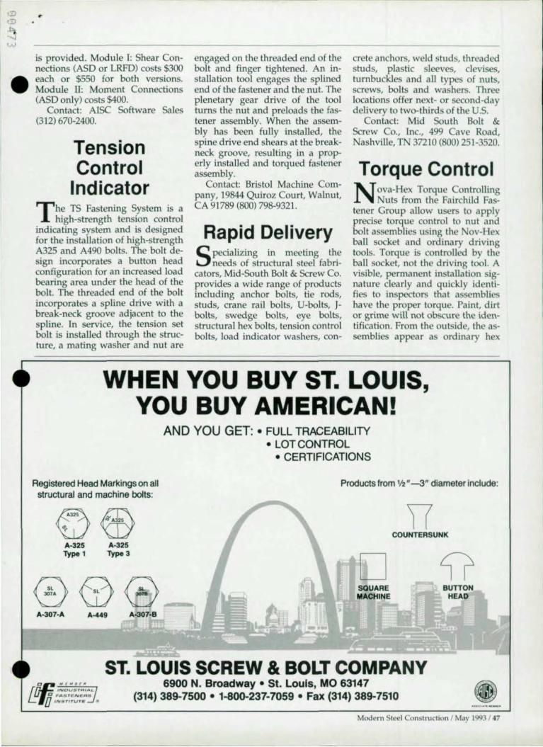
•
is provided. Module I: Shear Connections (ASD or LRFD) costs $300 each or $550 for both versions. Module 1I: Moment Connections (ASD only) costs $400.
Contact: AISC Software Sales (312) 670-2400.
Tension Control
Indicator
T he TS Fastening System is a high-strength tension control
indicating system and is designed for the installation of high-strength A325 and A490 bolts. The bolt design incorporates a button head configuration for an increased load bearing area under the head of the bolt. The threaded end of the bolt incorporates a spline drive with a break-neck groove adjacent to the spline. In service, the tension set bolt is installed through the structure, a mating washer and nut are
engaged on the threaded end of the bolt and finger tightened. An installation tool engages the splined end of the fastener and the nut. The plenetary gear drive of the tool turns the nut and preloads the fastener assembly. When the assembly has been fully installed, the spine drive end shears at the breakneck groove, resulting in a properly installed and torqued fastener assembly.
Contact: Bristol Machine Company, 19844 Quiroz Court, Walnut, CA 91789 (800) 798-9321.
Rapid Delivery
Specializing in meeting the needs of structural steel fabri
cators, Mjd-South Bolt & Screw Co. provides a wide range of products including anchor bolts, tie rods, studs, crane rail bolts, U-bolts, Jbolts, swedge bolts, eye bolts, structural hex bolts, tension control bolts, load indicator washers, con-
crete anchors, weld studs, threaded studs, plastic sleeves, clevises, turnbuckles and all types of nuts, screws, bolts and washers. Three locations offer next- or second-day delivery to two-thirds of the U.S.
Contact: Mid South Bolt & Screw Co., Inc., 499 Cave Road, Nashville, TN 37210 (BOO) 251-3520.
Torque Control
N ova-Hex Torque Controlling Nuts from the Fairchild Fas
tener Group allow users to apply precise torque control to nut and bolt assemblies using the ov-Hex ball socket and ordinary driving tools. Torque is controlled by the ball socket, not the driving tool. A visible, permanent installation signature clearly and quickly identifies to inspectors that assemblies ha ve the proper torque. Paint, dirt or grime will not obscure the identification. From the outside, the assemblies appear as ordinary hex
WHEN YOU BUY ST. LOUIS, YOU BUY AMERICAN!
Registered Head Markings on all structural and machine bolts:
©'" ffi '" A325
'l-
A-325 A-325 Type 1 Type 3
A-307-A A-449 A-307-B
AND YOU GET: • FULL TRACEABILITY • LOT CONTROL
• CERTIFICATIONS
Products from '12"-3" diameter include:
D SQUARE MACHINE
COUNTERSUNK
BUTTON HEAD
ST. LOUIS SCREW & BOLT COMPANY 6900 N. Broadway • St. Louis, MO 63147
(314) 389-7500 • 1-800-237-7059 • Fax (314) 389-7510
Modern Steel Construction I May 1993 / 47

•
F A S TEN E R PRO 0 U C T S sockets. But inside, there is a circular internal wall in which six carbide balls are arranged in a uniform, hexagonal pattern. Continued application of torque causes the socket balls to first brinell, then penetrate deeper into the lobes of the nut. Finally, the socket balls break through the resistance of the lobes to achieve a uniform, high level of torque control while leaving distinctive signature grooves.
Contact: Fairchild Fastener Group, One Civic Plaza, Suite 500, Carson, CA 90745 (310) 522-D700.
Proper Tension Installation
The Lejeune Tension Control Bolting System provides a cal
ibrated bolt, nut and washer assembly that installs at the proper tension for that particular size and grade of bolt. A non-impacting electric wrench drives the nut against the bolt tip. This contains the counter forces within the wrench and tightens each bolt to the required tension and then automatically causes the tip to shearoff, indicating proper installation. A-325 Type I and 1lI, as well as A-490, Grades are available in :¥4", 718", and 1 W' diameters.
Contact: Lejeune Bolt Co., 8330 West 220th st., Lakeville, MN 55044 (800) 872-2658.
Domestic Bolts
Lohr Structural Fasteners offers a wide range of domestic bolts.
The product line is mill certified, fully assembled and tested, and of the highest quality available.
Contact: Lohr Structural Fasteners, Inc., P.O. Box 1387, Humble, TX 77347 (BOO) 782-4544.
Construction Fasteners
A wide range of products are available from TC
Bolt Supply, including: swaged
48 / Modern Steel Construchon I May 1993
anchors; high-strength A325 and A490 bolts; studs; crane rail anchors; hook anchors; sleeve anchors; hook anchors; tie rods; square and round bend U's;double expansion shields; bent he-rods; eye bolts; drift pins; washers; turnbuckle and clevis assemblies; wedge type anchors; and arc weldments. A variety of coating and heat treatments are available.
Contact: TC Bolt Supply Co., Inc., P.O. Box 197, Forest Road, Greenfield, NH 02047 (603) 547-6371.
Fastener Coating
D orrlmate, an inherently black, zinc-rich coating is now
available from Magni Industries. A dry-to-the-touch finish, the coating is ideal for all construction fasteners requiring corrosion resistance, consistent torque tension, and bimetallic protection. The coating is applied over a zinc phosphate and sealed with an epoxy topcoat and is cost-effective compared with traditional electroplating.
Contact: Magni Industries, Inc., 255 South Woodward, Suite 300, Birmingham, Ml 48009 (313) 647-4500.
Steel Deck Fastener
T he Autotraxx ICH Deck Fastening System from ITW
Buildex is used to attach steel deck in a stitch or structural steel application. The system has two components: a stand-up tool that includes a screwgun, special fastener guidance system, depth sensitive nosepiece and unique drive socket; and Traxx fasteners with an ICH (Internal Cone Head) design. The fasteners have either a Traxx / 1 point for stitch applications or a Traxx/5 point for structural attachments,
For more information, contact: ITW Buildex, 1349 West Bryn Mawr Ave., Itasca, IL 60143 (708) 595-3549.
Shear Connections
T wo 120-page books from A1SC contain design aids for shear
connections. Presented in easy-touse tabular form, the books include designs for double-angle web bolted connections, structural tee single shear connections and single-angIe connections welded to the support. The books are available in both ASD and LRFD formats.
For more information, contact: Publications Dept., A1SC, One East Wacker Dr., Suite 3100, Chicago, [L 60601 (312) 670-2400 ext. 433.
Threaded Fasteners
Portland Bolt is a domestic manufacturer of headed and
threaded fastening hardware up to 51;2" diameter and 40' in length. The material is produced and certified to the latest AsTM and AlsC specifications. The company specializes in carbon, alloy, non-ferrous fasteners and hot-dipped galvanized coatings. An expansion has increased production and reduced lead times and costs.
For more information contact: Portland Bolt & Manufacturing Co., Inc., P.O. Box 2866, Portland, OR 97208 (800) 547-6758.
Bolts
Lewis Bolt & Nut Co. has been manufacturing bolts in 1927
and specializes in A-449 and A-325 fasteners in diameters of \1" or greater and lengths of 6" and longer. Products are made to order and rush orders are welcome. Certification and lot tracking are offered on all orders and all bolts are manufactured in the U.S. with domestic materials.
For more information, contact: Lewis Bolt & Nut Co., 604 Twelve Oaks Center, Suite 235, 15500 Wayzata, Wayzata, MN 55391 (BOO) 328-3480.
•
•
•
•
•
AISC ANNOUNCES
VOLUME II CONNECTIONS MANUAL ASD/LRFD
.... Volume /I Connections is a companion and extension to the AISC Manual of Steel Construction (both LRFD, 1st Edition, and ASD, 9th Edition).
.... Contains examples and information on steel connections not published anywhere else.
.... Has practical and economical examples of complex connection designs in both LRFD and ASD.
.... Based on the latest AISC LRFD and ASD specifications.
lII.p .
.... Covers bolted and welded shear, moment, and bracing connections In applications not treated in either the ASD or LRFD Manual of Steel Construction.
.... FREE BONUSI An updated copy of the AISC Code of Standard Practice will be sent with each book.
704 PAGES - ONLY $60.00 - ORDER YOUR COPY TODAY!
" " iESi"I'~~~; '~'~'~~'~~;~~~';;'~~~'~~~~;~~'~ ~ """···· ············ · · ··~~;~·r~;~·· ···················· · ·· · Send me __ copies at only $60 each. AISC Connections Offer
PO Box 806276 Name/Title Chlcago, IL 60680-4124 Company ________________________________________ __
Addre~ ________________________________________ ___
City/State/Zip ______________________________________ _
Phone __________________________________________ __
o Check enclosed o Charge my 0 Visa 0 MasterCard
Phone Orders 312/670-2400 X433
FAX Orders 312/670-5403
Please enclose remittanc e.
25% DISCOUNT FOR AISC MEMBERS
Accl# _____________________ Explres __ No COD orders. Add S5 for UPS
Signature charge. Foreign orders: S 10 mlnlnum for shipping.
STEEL MARKETPLACE HeJp Wanted
General Manager We fabricate short and long
span Joists, as well as girders and metal decking. Experience with steel fabrication mandatory. Total PIL responsibility.
Structural Engineer Registration and experience in
structural steel engineermg required. Must be able to manage engineering standards in oceor· dance with Sw('1 Joist Institute.
Theil(" poMllions aN! ror Valley JOISt., A DIVision orEOSCO Indutitne •• nnd are located In Ft. Payne. AL
Send resume to: Leon Sizemore, cio EBSCQ Induslric", PO. Box 1943, Birmingham, AL3520 1· 1943.
STUDY GUIDE 92. 10th EDITION
For Special Inspector ICBO exam. Siructural SleellWelding. Commentary and outline of
sections 10 stUdy In the UBC. UBC STDS, AISC & AWS Codes. Report writing, l.A. City Code, elemenls of plan reading . 140 pages.
Send $49 check or money order to: J A.Shernll
P.O. Box 371 Placentia, CA 92670
20 Software RISA·2D prOVides a fas\' Iruly inleractlve environment for Ihe
solution of a Wide range of structural design problems. Use RISA·2D for frames, Irusses, shear walls, conlinuous
beams and much more. Sialics and dynamics are included, wilh full sleel design .
For a free demo, contact : RISA Technologies, 26212 Dimension Dr., Suite 200,
Lake Forest, CA 92630 (800) 332·7472
CUSTOM DECK SOLUTIONS We can provide custom designed deck for unusual applicalions.
Long-spans, heavy loads, or special finishes are not new to us. Call us to proVIde an engmcered design for your unique needs.
Nicholas J. Bouras, Inc. 475 Spnngfield Ave.
Summll, NJ 07902·0662 ph: 908·277·1617 fax: 908·277·6789
Ram Analysis Steel Design Software Now. gel SBEA'" by Ram AnalYSIS ror only $100. Full renlured
compositeJnon-compOflLtc Illngle beam de8i~ and analYMis software I LRFO or ASOI. EIlMY·t.o-Use With Windows graphlcul Interface. Full 90 dJly money back guarantee.
Also 8v,ulablc, the RAM STEEL Integralt.'d Structural Software Sy.-tem Fully Ink'Rrated anolY818. dcslgn and drafting or .teel beams, JOII~: columnM. and baseplat(' .
Ram AnalYSIS 5315 Avenida EnCinas, Suite M, Carlsbad, CA 92008
Phone: 8001726·7789 Fax orders: 619/431·5214
CLASSIFIED ADS
Rcach 35.000 engineers, fabricators, architects, contractors, bridge officials nnd building owners inexpensively wilh a
c1af:lsified adverti~mcnt in Modem SLeeI Construction. It's faRt and ('a.~y-we'll even do the typesetting for you at no charge.
For rate a nd placeme nt in'onna tio n, call : Greg Poland at (708) 679·1100.
Or 'ax him 8 note at (708) 679-6926.
50 I Mod<'rn Steel Construction I May 1993
Structural Steel Detailing Experienced. AutoCAD CR121 based structural steel detailing office. Familiar Yo ith nil aspects of slt.'el construction 15 years detailing With ml'lnc units of measurement. Past proJect.s up to 6,000 tons. References/referrals available upon request. (Competitive prices & timely delivery.)
Ram Drafting (SI. Catharines) Ltd USA address:
• 172JA Niagara 81. Main Post Office Box 2629 Sl. Catharines. ON L2R4L4 Niagara Fall, NY 14302 Tel: 1·416·685·1835 USA Fax/modem: 1-416·685·6131
Advertiser's Index
AISC Prize Bridge Competilion ..................... 40-41
AJSC Software .................................................... Cill A ISC Volume II·Connections .............................. 49
Belhlehem 51eel Corp ...................................... 20·21
Bridgestone ............................................................ 24
icholas J. Bouras, Inc ........................................ CII
CDS ....................... .................. ................................ 19 C A Insurance ................... ... .... .. ..... ... .................. 39 ChaparraI5tecl ........................................................ 8
Computer; & Structures, Inc ............................ C1V
Com puler Detailing Corporation ....................... 36
Oesign Oalo .............. ................................................ 7
EJE Industries .............................................. ... .. ..... 37
Hilil ......................................................................... 42
J&M Turner ......................... .. .... ............................. 44 • Lejeune Bolt ........................................................... 45
MOX ................................. .... .. ................................. 38 Metrosoft .................. .. ............................................ 11
Mid·South Bolt ...................................................... 44
NSCC Can For Papers .......................................... 25
Omnitech ...................................................... .. ........ 36 Optimate ................................................................. 37
RMR ................. .. ................ .. ................................... 31
RAM Analysis ....................................................... 38 Research Engineers ........................................ , ........ 5 RJ5A Technologies ....... ................. ........................ 31
SCAOA Software ......................... .. ....................... 16 51. Louis Screw & Bolt ................................ .. ........ 47
Steel Deck Institule ............................................... 32
5IeeISOlubons ............................ .. .......................... 32
51ructuraiSoftware ........................ .. .. ................... 17
TradeARBEO ........................................................... 3
Voss ............ .. ............................................ ............. 33 Vulcraft ............................................................. 26-27
Whilefab ............................ ................................... 13
•

•
•
•
STRUCTURAL S TEE L DESIGN
CONXPRT A knowledge·based, menu-dri· ven PC software system lor the design of connections in steellramed buildings. All strength limit states are checked and expert advice Irom long·time lablicator engi· neers is used to augment the design rules. • Generates cope sizes, allows bolt stagger and perrnlts different bolt diameters 10< shop and field use • Designs can be sto<ed on disk, allowing electronic communication between design parues. • Generates complete reports showing details and strength 10< each limit state checked.
3· 112" or 5· 114" disk MODULE I: SHEAR CONNECTIONS 1 SI edition LRFD
Version 1.02 $300 9th edition ASD
Version 2.0 $400 MODULE II: MOMENTCONNECnONS ASD lormal only $400
STEMFIRE Determines sale and economi· cal fire protection lor steel beams, columns and trusses. Based on rational procedures developed by AISI which ex· tend the published UL fire resistive designs to other possible rolled structural shapes and common protec· tion material requirements.
Two 5·114" disks & users manual $96
(sorry. no 3· 112"
SOFTWARE FROM AISC
WEBOPEN Designed to enable engineers to quickly and economically design beam web openings. Uses state 01 the art criteria and features a clear and logi· cal data entry system with easy·to·use color coded input windows. Wnnen by pracbcing engineers lor engineers, incorporating expert design checks and waming messages which enhance the application 01 the AISC Design Guida-Steel and Composite Beams wilh Web Openin~to specific design problems. 3·112" or 5·114" disk. Includes
AISC Design Guide $495.00
~_r\'/.f 1-/ "" / ~
--j- - _.n Irl ~ 1'/' ""~
'IOeD IIIOffi 8 lOrn HPIOCD c [DO IIc[DD
AISC FOR AUTOCAD
Saves time doing detail draw· ings 01 structural steel shapes in AutoCAD. Lists properues corresponding to data in the most recent LRFD and ASD manuals. Parametrically draws to scale the end, elevation and plan views 01 common shapes. 3·112-or5·114-disk $120
112 F.ctom:l Moment Envelope:
ELRFD A new sophisticated program 10< interactively checking structural steel building components lor compliance with AISC specification. Checks whether member satisfies all limit states and limitabon requirements set by the LRFD Specilication and reports which sections are sabsfied or violated. • Review in deta~ the formulas and rules used in the evaluation and interactively
assess any mathematical expression on the screen. • Fully interactive MS Windows· based user interlace. • Disk includes ELRFD CheckfBrowser, AISC Structural Shapes Database and sample problems • User GUide and Relerence Manual .
3· 112" disk only $495
AISC DATABASE
Contains the properoos and dimensions 01 structural steel shapes, co<responding to data published in the most recent LRFD and ASD Manuals of Steel Construction. Presented in the ASClllormat for W, S, M, HP and other common shapes and channels. Available in U.S. customary units or metric units. May be converted to Lotus 1·2·3 PRN Io<mat.
3·112" or 5·114- disk $60
ORDER YOUR AISC SOFTWARE PACKAGES TODAY ~ASTERCARD V I S A
CALL (312) 670-2400 FOR FASTER SERVICE FAX YOUR ORDER (312) 670-5403
OR SEND MAIL ORDERS TO: AISC SOFTWARE. P.O . BOX 806276, CHICAGO, IL 60680-4124. ALLOW 2-3 WEEKS FOR MAIL ORDERS; 7- 10 DAYS ON PHONE, FAX ORDERS.
CREDtTCARDSONLYON PHONE, FAX ORDERS

C 1991 Comput~rs & StructuIes. Inc
For fTIOl'(" mfdimatlon
Compute. .. SlJUclW'es. 1Dc:. 1995 Ulllv"sily Avenue BerkallW. Califorrua 94704 TIL: (110) 845-2177 FAX: (510) 845-4096
•
ETABS 15 a mg1steled trademark of CSI • SAP90 IS a trademark 01 CSI