Embed Size (px)
Citation preview
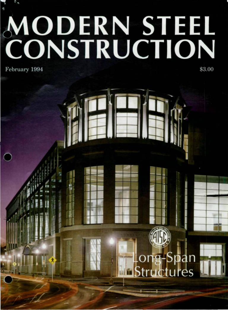
NEW COLUMBIA JOIST CO. P.O. Box 31· New Columbia, PA 17856-0031 717-568-6761 ·717-568-1001 (FAX)
JOIST DESIGN DATA SHEET
No.2
HOW TO DESIGN FOR WIND UPLIFT
Wind uplift forces must be determined by the design professional and shown on the contract drawings as NET UPLIFT. (The net uplift force on the roof joist is the gross uplift minus the dead load including the joist weight.) This temporary reversal of loading creates compression forces in the bottom chord which, as a result, may require lateral bracing. The Steel Joist Institute (S11) recognizes this by specifying a single line of bridging 1ll<lII the first bottom chord panel point to brace the bottom chord. The remainder of the bottom chord must be checked by the joist company (NCJ) to see if the S11 standard bridging is sufficient to brace the members in compression. The webs (diagonal members) of the joist can also be subject to stress reversal and this may require a reduction in the end panel space to accomodate the resulting compression in the end web. Thus the web layout may change from the standard dimensions published in the NEW COLUMBIA JOIST COMPANY catalog. The modified joist model is checked for the normal downward loading of the dead plus live loads and the worst case is used to determine the joist components.
r r r r r r ~
First BOllom Chord Panel Point
t t t NET UPUFT. PLF
/ , , , / ,
/ , , , , , / , , ,
r Standard Bridging r
r r r r r r ~
First Bottom Chord Panel Point
{,NCJ/ • NICHOLAS J. BOURAS. INC. PO BOX 662. 475 SPRI NGFIELD AVE. SUMMIT, NEW JERSEY 07902-0662 (908J 277-1617

• HISTAA@ 'truss girders
Lighten your Overhead with ASTM A 913 / A 913M Grade 65.
Assembly Building for the New Boeing 777 Aircraft. 3,000 tons of \RHED IST\R0 Grade 65 in the trusses-Span 354', Depth 28'_
Structural Engineer. The Austin Company. Scanle. WA. Steel Fabricator/Erector: The Herrick Corp., Pl c~anton. CA.
Contractor: The Au-.tin ('ompany. Seanlc. WA. Owner: The Boeing Company. Seattle. WA.
Seven Good Reasons to Use HISTAR® on Your Next Project! I. A TM A 913/A 913M. 2. High Strength: H1ST\R® Grades 50 and 65.
Available in most sizes in Groups I through 5 (ASTM A6 Table A). 3. Weldable Without Preheating - AWl Welding Report 91-002, 1992. 4. Excellent Toughness. 5. Good Ductility. 6. Reduction of Weight / Cross Section - Less teel to Buy and Weld. 7. avings in Transportation, Handling, Fabricating and Erection Costs.
1I1 ~1 \R .\ J n:~I'ICn..-d Irallc nurl. III ·\RBI [)
~ complete information, availability and literature, contact II d. H In D, Inc., 825 Third Ave., New York, NY 10022. (212) 486-9890, FAX (212) 355-2159. In Canada: Irade \RBH) Canada, Inc., 390 Brant Street, Suite 300, Burlington, Ontario L7R 4J4. (416) 634-1400, FAX (416) 634-3536

MODERN STEEL CONSTRUCTION
Volume 34, Number 2
MODERN STEEL CONSl~CTJ_ON ,. 11~1· 1 · ill ' ~ . -.
J~~ Milllli lihili ; ~ I ., .
• ~! ---
,. , iii fi r i I I 1[1 ~JIII III I I , I
... .. ! I q I 1'1 II ••• 1 " I
~ ! , .... i7f!i: •
To nleet s it e cons traints , the Rhode Island Convention Center was designed with a vertical orien· tation. The story behind this unique structure begins on page 28.
Modern Steel Construction (Volume 34, Number 2). ISSN 0026·8445. Publ;shed monthly by the American Inst itute of Steel Construction, Inc .• (AlSO, One East Wacker Dr., Sui te 3100, Chit ago, Il60601·2001 .
Advert ising office: P,l!tis/1M, O'Hare l ake Office Plal<l, 2400 E. Devon Ave., Des Pla;n .... Il 606 18 (708) 699·6030.
Subscription price: Within the U.S.-sing le issues 53 ;
3 years S85. Ou tSide the U.S.-Single issues S5 ;
I yearS36; j years $100
Postmaster: Please send address changes 10 Modern Sleet Con~lrucllon, One East Wader Dr., Suite 3100, Chicago. IL 6060 I· 200 1
Second class postage paid at Chicago, Il and ill addilional mailing offices.
4 / Modern Steel Conslnlction I February 1994
February 1994
FEATURES 18 Erection And Constructability Issues For
Long-Span Roofs A look at lessons learned on a series of long-span construction projects
28 Meeting Vertical And Horizontal Constraints A new generation of vertically stacked convention centers fit into urban cores without destroying the city grid
30 Spanning Hockey's Newest Pond
37
40
The roof of Anaheim's new arena clear spans 329-ft.-by-444-ft. to provide uninterrupted views
Cost-Effective Energy Dissipating Connections Slotted bolted connections show promise of becoming an inexpensive, easily designed method of energy dissipation in seismic areas
Blind Bolting Twist-off blind bolting can provide an alternative to welding for tubular steel
DEPARTMENTS 6 EDITORIAL 15 STEEL CALENDAR
-Innovative Practices 9 STEEL In Structural Steel
INTERCHANGE - National Steel - Loads for temporary Construction Conference
bracing - Higgins Lectures - Clips vs. hook bolts - International
for crane runways Conference on Fatigue - Seal welds
47 CONNECTION 12 STEEL NEWS PRODUCTS
- Move To State-Required CEUs Gains 50 STEEL Steam MARKETPLACE
50 ADVERTISER'S INDEX
•
•
•

STAAD - 111/ ISDS Release 19.0 ,-,
• Introducing Concurrent Engineering to Structural Software
r---- What's New? ------, A Milestone in Computerized Structural Engineering
•
• Concurrent Graphics User Interface: Build the model, Perform AnalysisIDesign, Review results. and Generate Reports concurrently
• State-of-the-art Report Generator
• New Advanced Analysis/Design Facilities: Tension Only Members Finite Element Release Specs Incl,ned Supports HarmonIC Time History Load Generator
• Advanced Automatic Element Mesh Generator
• On-screen error display with on-line editing
• Live on-screen analysis/design status display
• Full-scale PC and Workstation version including: SUN. HP. DEC. SGI. IBM RISC implementahon.
STAAD-III/ ISDS Release 19.0, from Research Engineers, Inc. represents a milestone in Computerized Structural Engineering. Built around a new Concurrent Graphics User Interface, the new rel ease allows you simultaneous on-screen access to all facilities.
Build your model, verify it graphically, perform analysis/design, review the results, sort/search the data to create a report - all within the same graphics based environment. This "concurrent engineering" approach coupled with a live relational database, enhances the productivity of your design office to a level never witnessed before.
STAAD-IIIIISDS - from Research Engineers - is an acknowledged world leader in structural software. Whether it is linite element technology or sophisticated dynamic analysis or CAD integration, Research Engineers had always been at the forefront of innovation . TAAD-II IIISDS has been consistently ranked #1 by all major industry surveys including ENRlMcGRAW-lIill survey.
With over 10,000 installations, 1110re than 30,000 engineers worldwide rely on STAAD-IIIIISDS as their everyday companion in the design office .
I I Research Eng,'neers Inc 1570 N. Batavia Street. Orange . CA 92667 .. ,. ,. Tel: (714) 974-2500 Fax: (714) 974-477t Toll Free: (800) FOR-RESE
• USA • UK • GERMANY • FRANCE • CANADA • NORWAY • INDIA • JAPAN • KOREA

Editorial Staff Scott Melnick,
E
Editor and Publisher Patrick M. Newman, P.E.
Senior Technical Advisor Charlie Carter,
Technical Advisor
Edito ria l Offices Modern Steel Construction One East Wacker Dr., Suite 3100 Chicago, IL 60601-2001 (312) 670-5407 Fax 312/670-5403
Advertising Sales Pattis-3M O'Hare Lake Office Plaza 2400 E . Devon Ave. Des Plai nes, IL 60018 (708) 699-6030 Fax 708/699-6031
AISC Officers Frank B. Wylie, III,
Chairman Robert E. Owen,
First Vice Chairman H. Louis Gurthet,
Second Vice Chairman Robert D. Freeland,
Treasurer Neil W. Zundel,
President David Ratterman,
Secretary & General Counsel
Lewis Brunner, Vice President, Membership Services
Geerhard Haaijer, Vice President, Technology & Research
Morris Caminer, Vice President, Finance/Administration
o T o R A L
Putting The Professional Back
In P.E. W
hat do Iowa. Alabama. West Virgini a and New Jersey all have in common? They' re pioneers in requi ring continuing education as a prerequisite for the professionallicen\ ing of engineers.
Hurray for them. and all the other state licensing boards which are considering a similar requirement (for more informmion, turn to page 12). Engineering is not a static profession and practicing engineers need (0 maintain their knowledge of the latcst developments in their indumy. With the pri vilege of approving design drawings comes the re~pon s ibil i t y for maintaining their expertise.
•
The task of obtaining 15 hours of continuing education (the typical requirement) ~hould be simple for moM engineer" given the wide range of acti vi ties that meet the requi rement : loca l or in- house seminars; attendi ng convention~: speak ing: writing paper~ ; attending profes,ional l11eet ing~: or, in some cases. taking a videotaped course. Engineers in Iowa and Alabama- the only two ~tates with experience in requiri ng continu ing education- report that obtaining • the needed number of hours has not been a problem. For example. attending the National Steel Construction Conference in Pimburgh this May can provide nearly all the required hours. Need more hours" AISC Semina" are being held this year th roughout the country.
The requirement is not without potential pratfa lls, however. Some engineers are hesitant to give the state the power to determine what courses are allownble. Others worry about adding another layer of government bureaucracy. Stories about problems in dealing wiLh government agencies are certainly legion. For ex ampl e, a close fri end of mine rece ntl y had a run- in wi th th e I llinois Department of Registration and Education- the agency that licenses engineers and. in her case, occupational therapists. Renewing her li cense should have been the simplest thing in the world . There' s nothing to verify. All she needs to do is send in a $40 check before the end of the year. Well . that 's not strictly true. She needs to send it in far enough in advance for the Illinois bureaucracy to handle it. Unfortunately, Illinois doesn't stagger its license renewal. so it takes at least eight weeks before they can even veri fy that they have received a check, let alone begin to process the renewal applicmion. If thi s type of bureaucratic bac klogg ing is commonplace, then engineers will have something to worry about. Hopefully, it 's not- again , engineers and Iowa and Alabama do not report similar problems.
Continuing education is important. If engineering is to maintain its statllS1
then indi vidual practiti oners mu st endeavor to fulfill the requirement s of professionalism-and that incl udes staying up-to-date with the latest infonnation in the engineering field . SM
• 6 1 Modern Steel Construction / February 1994
'YD '.D ,;p
'''' ,.;
•
•
•
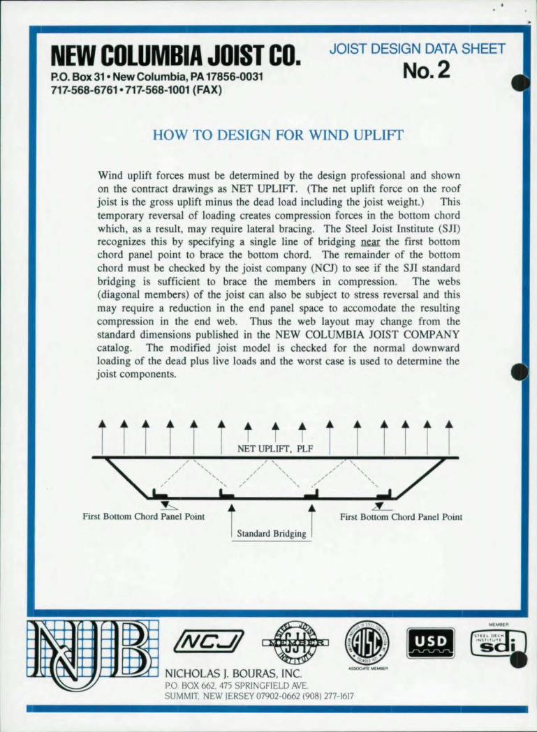
How to get from here
Engineering, Anal}'sis and Design Module
I - ----
Estimating Module Production Control Module
• Detailing Module
to here.
Design Data's SDS/2 Steel Fabrication System. SDS/2 gives you the flexibility to integrate all aspects of your business with one
software system. That concept is called Information Management. Each module by itself will save you time and money and by combining products to implement Information Management you receive more than twice the benefit in savings and productivity So whether you need one SDS/2 software module or all these tools working together, Design Data can provide the most productive system for you.
For more information about SDS/2, information management in the steel industry or future product demonstrations call 800-443-0782.
DES1GND DATA III "First in ... software, solutions, service"
402-476-8278 or 1-800-443-0782 IQQ! ~ 1"'l2lDrpMUOCI

~----------------------------------------------------------------------------------- -----
INC. THE ALRISAFE FASTENING SYSTEM
II 29 Flagstone Drive,
Hudson, N.H. 03051 U.S.A. Tel: (603) 883-1660
Telex: 953033 Fax (603) 882-9165
The fastest , safest, most economical system for attaching steel roof and floor deck .
• FaSI...live to len lime~ faster than welding. screwing or u~ing powder "cIliated tools. providing the lowest inplace faMcning cm.t. • SJfe ... l11eel~ or exceed~ all O.S.I I. A. safety requirements • Easy-To-Use ... uprighl tool design for C'1SC of operation and les!) operator f.1Iiguc. No cleaning or oiling required. • Positive Alw,chmcrlls ... no burn- Ihroughs. No paint louch-up needed. No toxic fumes and no fire hillard. High fastener holding power, both in tCllllilc :lnd shear strength . • FaclOry Mutual Research Corporation (Cla~s 1-90 wind uplift rc;iSlancc) Rcpen Nos. 28234 & J.L. I R8A6.AM .
• Steel Deck Institute (West Virginia University) Report No. 2018·l by Dr. l.D. lULlrel!. Ph.D .. P.E.
• Job Site Salc~ & Service
Sampling of recent Pneutek Deck Projects • BMW Automobi le Plant (1.650.000 ''I. ft.) • Winn Dixie Di~tribulion Center (1.450.000 ~q. ft .) • Saturn PlantiGM Corp. (10.000.000 sq . ft .) • Eddie BaucrlSRCigel Distribution Center (1.3000.000 ''I. n .) • Toyol" Plattl (Ph",e II ) (2.000.000 sq . ft .) • K-Mart Distribution Center (1.500,(X)(} sq. ft.) • Scars Dislributing Center (1.500.000 sq . ft.) eAnhcu:-.cr- Busch Brewery ( 1.500.()()() ~q. ft.)
•
• r----------------------,
your copy now!
Instruction Manual
for installing
HIGH·STRENGTH BOLTS -DIRECT TENSION INDICATORS
(ASTM F959)
ENGLISH UNITS EOITION
~ ~ J& M TUrner Inc.
J&M Turner Inc. International Headquarters Phone 215·953-1118 1310lndustnal80ulevard 800-525-7\93 Southampton PA 18966
Fax 215-953-1125 Telell. 268965
OESCON DESIGNS AND DETAILS STEEL CONNECTIONS
! ·It. y. j.::m::j!
FOR A FREE DEMO DISK CALL OR WRITE TO
OMNITECH ASSOCIATES P.o. BOX 7581
BERKELEY, CA 94707 658·8328

•
•
•
Steel Interchange Steel In terchange is an open forum for Modern Steel
Construction readers to exchange useful and practical profes· sional ideas and information on all phases of steel building and bridge construction. Opinions and suggestions are we lcome on any subject covered in this magazine. If you have a question or problem that your fellow readers might help you to solve, please forward it to Modern Steel Construction. At the same time, feel free to respond to any of the questions that you have read here. Please send them to:
Answers andlor questions should be typewritten and doublespaced. Submittals that have been prepared by word-processing are appreciated on computer diskette (either as 8 Wordperfect file or in ASCII format ).
The opinions expressed in Sleellnlercliange do not necessarily represent an official position of the American Institute of Steel Construction. Inc. and hove not been reviewed. It is r('cognized that. the des ign of s tructures is within the scope ond expertise of a competent licensed structural engi neer, architect or other licensed profeSS ional for the llpplicalion of principals to a particular structure.
Steel Interchange Modern Steel Construction
One East Wacker Dr., Suite 3100 Chicago, IL 60601·2001
Information on ordering AISC publications mentioned III
this article can be obtained by calling AISC at 3121670-2400 exl. 433.
Th e following responses from previous Steel Inte rchange columns have
been received:
When asked to design a temporary bracing system for steel beams and columns during the erection phase of construction, what loads are us ed and what factors of safety are employed for the bracing and its connections?
The primary source for the loading requirements for temporary bracing is the
AlSC Code of Standard Practice Section 7.9.1 which states that the temporary supports are to be designed for " ... Ioads comparable in intensity to those for which the s tructure was des igned, r esulting from wind, se is mic forces and erection operations , but not loads resulting from the performance of work by or the acts of others, nor such unpre· dictable loads as those due to tornado, explosion or collis ion ." It s hould be n oted that stee l frames are open structures and may have wind loads greater than predicted by the projected area of the completed building. Also partially completed cladding may add to loads in the supports for non-self-supporting structures. The topic of erection bracing and the loads applied to it is discussed in detail in a paper by Fisher and West published in the Proceedings of the 1993 SSRC Conference held in Milwaukee.
(Information on obtaining a co py of "I s Your Structure Suitably Braced" can be obtained from the Structural Stability Research Council by ca llin g 21517 58-3522. ) Michael A. West, P.E. Computerized Structural Design Milwaukee, WI
Wben is it appropriate to use clips instead of hook boIts to secure rails for top running crane runways? What are service versus cost considerations?
I n general, hook bolts can be used for attaching ra il s for li ght duty , s low moving
cranes and clips are used for heavy duty , faster cranes. the dividing point is arbitrary. Howeve r , hook bolts s hould never be used for heavy duty cranes as they are not strong enoug h to r es ist the late ral forces likely to be present. Clip plates, on the other hand, can be used for the full range of crane s izes but, for smaller cranes, it may be impossible to place the required gauges in the crane beam and cap channel. Thi s is the s ituation where hook bolts ca n be used . There is a third option for attaching r a ils to c ran e beams-proprieta r'y adjustable clip devices which are welded to the tops of t he crane beams. Crane rails should neve r be welded directly to the crane beams, regardless of crane s ize.
When considering th e economics of hook bolts vs. clips there is
nothing to consider. One must do what must be done. If one owns a Ferrari , one should not worry about th e cost of h igh octane gasoline. A crane runway is a dynamically loa ded structure placed inside a statically loaded structure and must be treated as such. Hook bolts a re usually a purchased item, the rail s must be punched or drill ed to receive them, and t hey must be moni tored frequently to kee p them tight and to assure proper alignment of the ra ils. Rai l clips are easi ly fabr·icated by most fabricators , the crane beams must be punched or drilled, a lignment is more positive, lock nuts or full y torqued hi gh strength bolts are required.
For the sake of this discussion light duty could be interpreted as CMAA classes A2 and B; heavy duty as CMAA classes A1, C, D , E, and F . E ach cr ane capacity has its relative speeds, for instance, 150 ft per minute would be s low for a 50 ton crane, medium for a 100 ton crane, and fast for a 150 ton crane. For further information see, Tips for Avoiding Crane Runwa y Probl e ms, AISC Engineering Journal , Vol. 19, No.4 (1982 ), pages 181-205. David T. Ricker, P.E. Payson, AZ
When welding to AWS 01.1 requirements what is a "seal" w e ld and what are the apl>licable inspection criteria for the same?
Modern Steel Construction 1 February 1994 / 9
Steel Interchange
ftJeal weld is designed primarily to provide a specific
egree of tightness against leakage, or melt-through, until the final weld meets the requirements for throat size in assembly gaps of 5/16-in. or less. The seal weld is not included in the integrity inspection of the weld itself. David L Simpson U.S. Army Corps of Engineers Muscat, Oman
AWS A3.0 defi n es a seal weld as "any weld designed primarily to provide a specific degree of tigh tness against leakage." This does not define the type of weld but rather its intended function.
AWS Dl.1 does not address the specifics of a seal weld, however for a weld to con
form to the requirements of AWS Dl.1 it must meet the prequalified criteria of Section 2 (un less qualified thro u gh testing). Consequently any type of prequalified weld which is applicable to the given joint may be used as a seal weld. The inspection criteria for the weld would be the same as if it were used in a structural application.
This may seem excessive to some readers but conside r one recent example:
A construction elevator derailed because a seal welded cap plate on the tube support breaks away a ll owing the support to fi ll with water. The weep holes were clogged and during the winter months the water froze deforming the support. Neal White, P.E., CWI Special Testing Laboratories Hartford, CT
New Questions Li sted below are questions
that we would like the readers to answer or discuss.
If you have an answer or suggestion (or an additional question) please send it to the Steel
Interchange Editor, Modern Steel Construction, One East Wacker Dr., Suite 3100, Chicago, IL 60601-200l.
Questions and responses will be printed in future editions of Steel Interchange.
I n designing composite steel girde rs in accordance with the LRFD Method, it h as
been well establ ished that sign ificant reductions in beam sizes can be achieved. However, in my experience, I have found, in some cases, the more economical girder sizes derived may be unsafe during unshored wet concrete construction. This can occur when the metal deck runs parallel to the girder and, in my judgement, does not afford significant lateral restraint to the top nange of the girder in compression. For thi condition, the unbraced length is t he spacing between the beams supported by the girder. Significant reduction in the non-composite moment capacity can occur due to lateral torsional bucking which may not be adequate for the unshored wet concrete construction.
No criteri a for this serviceability problem or guidance appears to be given in the LRFD specification. I would like to know whether there has been any testing or research to demonstrate that metal deck, parallel to the girder does indeed provide adequate restraint or that checking the beam size for the tem porary construction condition, shou ld be carried out as outlined above. Peter J. Maranian, S .E. Brandow & Johnson Associates Los Angeles, CA
When designing using the ASD Manual, what is the allowable weak axis
bending stress on channel? The manual does not seem to specify this. Adam Samuel Riley Stoker Corp. Worcester, MA
to I Modern Steel Construction I February 1994
When welding a steel that • has dual certification (A36 and A572 01'50) is
there a low hydrogen electrode requirement?
A36 is a group I base metal and ASTM A572 is a group II base metal. Is Aws Dl.1 Table 4.1, note 1 applicable to this condition? Neal White, P.E., CWI Special Testing Laboratories Hartford CT
N ox at the top of each Steel Interchange contains a entence that has caused a
lengthy discussion in the office . The sentence i as follows: "It is recognized that the design of structures is within the scope and expertise of a competent licensed engineer, architect or other li censed profes ional for the appli cation of principals to a particular structure."
Fellow office members did not understand the asse l'tation made by the sentence. We think it • means architects and other design professionals can practice the art of sizing structural mem-bers. If we have the correct meaning, then t hi s presents an open connict between two design professions. We could only guess at the meaning of "other li censed professional." Please tell me we do not understand the sentence. We fear that the meaning is an example of further eroding of the position professional engineers active in the design of structures enjoy. Persons not trained nor li censed as professional engi-neers competent in structures, use competitive methods which the average buyer may not understand. Perhaps a better comment would be expla ining the many benefits of hiring the trained professional with the legal authority to assume responsibility. Robert E. Ferguson, P.E. Engineering Enterprises, f l1c. Bloomington, MN •

• High Strength Structural Steels From Chaparral Put The Heat
On Everything Else.
To di,cmcr the 111 .. 111) ath.lIllagc, of Ch,tparral', lugh "trcnglh "'!nIl'luml 'icci. PUI 11 up again'll an) other con,trutlioll material.
Price. Pru.:c" nne (lIthe grl.!alc', \trcngth, of ChalMlTi.lI \t-.:-el. In fat:t, \teel, .. k" ~Xrc'hl\-':- h){j.t) th.m II ".h 10 )ear ... ago. SO )OU Gill no" gel all the ~ndl" of \trut:lUr.lI ... h:cI .11 \ Inuall} the prll.:e of rehar
AVCII1alMlity. \1 Chaparral. th~re""no \\.111111£0 on rollmg ... chedulc\. W-.:- .Ire a ... tlx:~ing mill \\ 11It.:h 1ll~'IIl' our 111\ cllIonc, .u~ read) "hcn )nu need thclll. And heC<lU\l' ",c'rc c~llIrJlI\ Ilx:;\tcd III ~tldIOlh"lIl, Tc\;.t .... \\C·GIIl £Oct )' our order to you 1"<1..,1, 110 mJth:r \\ here you ,:lrC
.. ~~'S:r'C~~'11 ioncercd \to(:~ a\;'lIlahdll\ 01
AST\1 hi~h ... Ircnglh <,fccl; <It the ,:II11e pncc of ASli\.1 A.lo 'Ieel .... Englnee ...... call no\\ upgr.ldc m.uenal \.n:nglh \\ lthoUI ra''''lIlg thc co .. ". Ccrtifled AST\1 A57~ grade 50, A529 grade 50, \l6. c:'lI1i.1dliln..w Wand SOW
are all rc,ldd\ a\;,ilahk al une 10\\ A36 pri~l'
• • ••
Easy To Design With. ro(ll)'" cnglllcc,", ;Ire ftl1(.hll~ ,led i .. [he ca,":\[ m:Hcrial tn dC\lgn wllh h) 1'0If. Many u .. c av'lllahic ... olt~.m: piH.:k.agc, Ihal 'IInpl) OOIl', c\I'IIOr nlhcr millen;!". \nd II )OU ha\C' an) prodUl"! qUC\llOn ... c'llCn help '\ only a phone Cilll 11",1) Ju" COlll.tl'1 AISC lor cll!!inccflng il""I.UKC at f.'\ I:! tfl70-1\-' 17
R8C) 1\01 onl) i, .. tecl il rcqdC'd pmdU4.:I. hut II', ill,u n..'I.:)l:hthk. L nllk.c other UlIl,InIl'IIUIl Ilhllcflal ... ,Icel eill1 eventually be ~rappcd. rcc)dcd ,tnt! rcu\Cd agam aod agam. I-:m ImnlllCnlall) 'itk. ,trel" good lor the luturc <lnd your cumr~m).
St~cll\ Ihe buddlllg muterial 01 the ~ hi centur}. And Chap.lrral I ... nne of the 1110\1 clllci~nl 'I~el pmduccr ... III thc "orld. We ha'Vc thc IlC\t prlce\ and thc he ... , ... er\ lI.:e. Callu .... and Ic.tm liN hand "h) Ihlllg ... an: he.lIlI1£ up .u ChaparrJ.1.
CHAPARRAL rnn
l 'lllhc IMWI)'!' r~Nh' 1~41
In 1~\J"O«Wh +L'6'~ hl t:!..t l ~WI \\anJ Road. \I.JloIhl:lh. I\, __ <1651

EDUCATION REP 0 R T
Move To State-Required CEUs Gains Steam
N early half the state registration boards are now considering requiring
engineers to participate in continuing education as a requirement for license renewal. The move began in Iowa in 1978 and it was more than a decade before a second state, Alabama in 1991, followed suit. Since then, two more states-West Virginia (effec tive in 1994 ) and New Jersey (effective in 1996l-have added requirements. And six more states are expected to soon join them.
Continuing Education Requirements For Professional Engineers
Most of the proposal s are quite similar and resemble those that have already been enacted. Alabama is typical and requires 15 Professional Development Hours (PDH) per year, with a maximum of 15 additional hours allowed to be carried over to the following year. In other words, an engineer must complete 30 PDH during every two year peri od. According to Alabama's rules, a wide range of activities qualify for PDH credit, including college courses, seminars , tutorials , short courses, correspondence courses, videotaped courses, in-house programs, and attending programs at technical or professional meetings. In addition, teaching and writing articles or papers qualifies for PDH credit. Generally, one hour of professional development education equals 1 PDH and one Continuing Education Unit (CEU) equals 10 PDH.
"As professional engineers working for a professional company, we've taken t.he requirement very seriously," states Alan Speegle, P.E. , Quality Assurance Coordinator for the Structural Department at Rust Engineering Co., a 40+ engineer company in Birmingham. "Continuing educa-
.~ • , o Currenlly requires
o Under considerallon
tion is very important to the profession. Engineering is changing-not in the end results, but in how we arrive at those results," Speegle explains. Rust has formalized the professional development process and has a central person responsible for keeping track of all emp loyees continuing education activities. They also hold a number of in-house seminars each year, as well as encouraging staff engineers to attend outside programs. "There are enough programs offered that it is not burdensome to us, though I can see how it might be at a smaller company."
But Bud Romei , P .E ., president of the four-engineer firm of Structural Technics in Irondale, AL, says he hasn 't found the requirement to be a problem. "I
12 / Modern Steel Construction I February 1994
o Under discussion
o Not being considered
think its a very important requirement. It enhances the entire profession. Continuing education is important to being what we claim to be-a professional engineer. It requires you to keep up with the latest developments. And 15 PDH is such a small number of hours that getting it is almost automatic. However, it does require people who al·e not really active to rethink their need for a license."
However Romei, who is registered in 13 states, did express one concern . "It would make it much easier if all states had a common form," he says. Fortunately, the states now considering adding continuing education requirements are cognizant of that desire. For example, Russell F . Geisser, P.E., a member of the registra-
•
•
•

• tion board in Rhode Island, says that when his state adopts a continuing education requirement, it will probably accept other state's requirements. "If an engineer met Alabama's requirement, that would be fine . We're not trying to be nitpicking or onerous." Likewise, Alabama's rules state: "Continuing educational requirements may be met without completing the entire renewal form if a registrant resides in another state which is listed by the Alabama Board as having continuing educational requirements acceptable to the Alabama Board and the registrant certifies in the appropriate section that all continuing educational and registration requirements for that state have been met." Geisser expects his board's recommendations to be firmed up shortly and public hearings on the subject to be held later this year.
Another objection that seems
to pop-up in discussions about continuing education concerns the need for older or very experienced engi neers to meet the requirement. While Alabama and West Virginia only address this issue as it applies to retired engineers, Geisser says he recommends that an exemption be given based on a combination of age and experience.
While most engineers favor taking continuing education courses, many oppose mandatory requirements, according to Ben Nelson, P.E., a senior project engineer with Martin/Martin, Inc., Wheat Ridge, CO, and committee chairman for continuing education with the Structural Engineers Association of Colorado (SEAC). In a survey of 90 structural engineers from 75 firms, 60% favored vo luntary standards whi le only 40')1 were in favor of state requirements. "A good number of engineers [75')1 according to the survey]
a lready meet a requirement for 15 PDH, but a lot of engineers have a problem with establishing another layer of bureaucracy," Ne lson says. Another question, he says, revo lves around who decides what qualifies. However, many state boards are ha ndling this question by recommending that the level of requirement be suggested by the engineering associations, rather than the state boards.
The urvey also revealed disagreement among engineers over reporting provisions. Seven out of 10 engineers favored leaving reporting up to the individual engineer while the remainder favored more stringent reporting procedures. Geisser a lso reported that some engineers in his slate had problems with requiring e ng ineers to keep t hei r own records. But Iowa, the only state with substantial experience in the matte r , reports that th is is not a problem. "We have vo l un-
WHEN YOU BUY ST. LOUIS, YOU BUY AMERICAN!
Registered Head Markings on all structural and machine bolts:
A-325 Type 1
A-307-A
A-325 type 3
A-449 A-307-B
AND YOU GET: • FULL TRACEABILITY • LOT CONTROL
• CERTIFICATIONS
Products from 'h" -3" diameter include:
o SQUARE MACHINE
COUNTERSUNK
BUTTON HEAD
ST. LOUIS SCREW & BOLT COMPANY 6900 N. Broadway • St. Louis, MO 63147
(314) 389-7500 • 1-800-237-7059 • Fax (314) 389-7510
Modern Steel Construction / February ]994 / 13

,
c ...
tary reporting with spot audits," says Patricia Peters, executive secretary to the Iowa Engineers and Land Surveyors Examining Board. Approximately 5')t of the renewing engineers are audited each year, and of those, mOre than 90'k have satisfactory documentation. Iowa has about 5,400 registered engineers and renews half each year.
SEAC is expected to issue a pos ition stateme nt early this yea r. Previous ly, the Colorado board recommended to the legislature that a continuing ed ucation requirement be established for land surveyors, but the legislature denied that due to a lack of administrative fund s. A requirement for engineers is till under di scussion in that state, however.
"I think that continuing edu cation to maintain your license is necessary ," says Ri chard Weingardt, P .E., president of Richard Weingardt Consultants, Inc., a large Denve r-based cons ulting engineering finn and president-elect of ACEC. "Many of us complain that engineers get no respect, but if we want the same respect as other professions we should be willing to meet the same require me nts. According to Nelson , teachers in Colorado are required to take 30 PDH over a two-year pe ri od , CPAs have a 15 PDH requirement per year, and lawyers and nurses have a PDH requirement of a pprox imately 20 hours per year, depending on their specialty .
The major professional engineering societies have, to date, resisted any proposa ls for mandatory continuing education requirements. For example, the National Society of Professional Engineers states that they can find "no compelling justification for any jurisdiction to adopt a continuing profess ional competency requirement .... " However, th ey do recom me nd that any state that does adopt a continuing education requirement uti lize th e mod e l require ment deve loped by the National
14 1 Modem Steel onslruction / February 1994
Council of Examiners for Engineering and Surveying, which is quite similar to Alabama's. NSPE's major objection, according to their position statement, is that approximately 70')t of the practicing engineers in the U.S. a re not registered and requiring continuing educat ion for the 30'k who are would be an unfai r burden . However, as others point out, with the privileges of regis tration come responsibilities.
Whil e ASCE h as not ad dressed the topic of state requirements for continuing education, a com mittee last April recommended against a continuing education requirement for ASCE membership. ASCE membership is clearly not unanimous on that point though, as is illustrated by a Decem ber 1993 Forum artic le by James W. Poi rot, P. E. , ASCE president and former chai rman of CH2M Hill in Denver. "r continue to believe there would be grea t va lue to individuals, ASCE and the civil engineering profession in establishing a phased continuing-education program as a condition of membership renewal," he wrote. Poi rot points out that the situation today is analogous to the situation at the turn of the century when states began licensing professiona l engineers. At that time, ASCE opposed li censing, a position they held until 1930. "Let 's hope ASCE doesn't take 30 years to recognize that the public, project owners and our non-engineering team me mbers ex pect engineers to provide evi dence that we are continuously studying the s tate of engineering practice and are current and competent in our field of practice," Poi rot writes. "The image of civil enginee rin g is e nhance d by requiring CPO because 'respect' comes from taking responsibility. On the other hand, our respect will dwindl e if we do not follow the other professions, uch as the American In stitute of Architects, as they commit to CPD as a condition of membe,'ship."
•
•
•

•
•
•
S TEE L
Steel Calendar
A n introduction to the new 1993 LRFD Specification wi ll high light a new four
part seminar series from AISC Marketing, Inc. I nnovative Practices In Structural Steel also wi ll provide information on state-of-the-ar t structural steel design software, the la test
EHRP Seismic Regulations , and a review of Semi-Rigid Composite Connections.
The new 1993 LRFD Specification is the first major revision to the original 1986 LRFD Specification. The lecture will include a discussion and explanation of the major changes, including such items as the stability of unbraced frames, web crippling equations, slipcritica l joints at factored loads, alternative fillet weld design strength and Chapter K clarifications.
The session on Software for tructural Steel will demon
strate methods for using the latest steel design software to create the more efficient designs. Also, a practical transition to LRFD will be explored. Integration in designing various elements and connections in steel a lso will be featured .
National building codes have undergone a major overhaul on their rules for seismic design of bui ldings as recommended by the Building Seismic Safety Council and federal agencies. This lecture will cover the "why" and the "how to" of these changes, and their impact on steel de ign.
And finally, the lecture on semi-rigid composite connections will explain the use of this very economical system.
The seven-hour, four-part seminar cost $90 ($75 for AlSC members ), including dinner. The lecture has a EU va lue of O.4.For more info rmation, ca ll 3121670-2400.
NEW S
1994 Seminars
S~ln Diego Irvine S.l( r.1menlo S~ln rr<lIlCis(o Lo .. Angeles Seattle Salt Lake Cily Phoenix Porliand, OR l~l' Vegas
WEST
MIDWEST Chicago 51. loui~ Dl'<' Moines Mllw~lukee Minl1(:,~lpoli ... DC'lroil Indianapolb
NORTHEAST Ml'nden Bo,lOI1 Portl,lnd, ME New York Albany Rochester
SOUTHWEST New Orlean~ Alburquerqlle Denver h.,1I1"'JS City Soln Antonio OJ lias Iiouston O~I"homa Cily
Gfl>('nville Charlotte Raleigh Birmingham AII,1I1Ia Richmond M(>mphis Miami Orlando
SOUTH
MID-ATlANTIC Baltimore W,1;hinglon, DC PlllSburgh [dison, NI Philadelphia (I,,>eland Columbus Cincinnati
3/17 4/21 6/1 5 6/ 16 6/2l W27 9/29 10/20 11/ 15 11 / 17
l/8 3/24 5/5 5/ II 6/2 10/ 11 10/ 13
1/1 1/2 2/1 4/ 14 9/13 9/14
2/8 2/10 2/17 lIl0 l/15 4/19 6/21 9/8
3/1 3/2 1/1 5/3 9/20 9/22 10/18 11 / 1 11/1
4/5 4/7 4/1l 10/4 10/6 10/25 10/26 10/27
fI)
I • •

Curved and Straight
Steel Bridge Girder design & analysis on your PC
Integrated Grid Analysis & Girder Design Metric or English
• Influence sur/ace (grid) or influence line approach (grid or line girder) • Complex grid and roadway geometries. plate and box girders. rolled shapes • 1992 AASHTO Spec .• 1993 interims. 1993 Curved Girder Guide Spec. • Composite action control. fa tigue control. slab pour sequencing analysis • Excellent for the design or rating of curved and straight girder systems
Available by lease or license For more information, or a 30-day trial, contact:
MDX software Phone (314) 446-3221
Fax (314) 446-327 8
S 'I ,rr. $50 for promotional version of peClQ oJJer: I' ',,l d ' me glruer eSlgn program
ANCHOR BOLTS, PLATE & SLEEVE ASSEMBLIES, TIE RODS, STUDS, SWEDGE
BOLTS, U-BOL TS, HEX BOLTS & EYE BOLTS
Custom fabricated to exact specifications from certified domestic steel up to 4-inch diameter and 4O-foot lengths in steel & alloy.
STRUCTURAL BOLTS, NUTS & WASHERS In A325, A490 & TENSION CONTROL BOLTS, WELD STUDS, CONCRETE ANCHORS, B·7 STUDS, CLEVISES, TURNBUCKLES and all types offasteners in various grades and materials; plain, plated and galvanized.
Stocked for immediate shipment
* SAME DAY SHIPPING * OVERNIGHT TO MOST U.S. CITIES
MID-SOUTH BOLT & SCREW Centnll Slale. 499 Gave Road
Nashville, TN 37210 61 5-88H341
FAX: 615-88H542 1-800·251-3520
East Coalt 59 lbef1y Road
ErrjlOna. VA 23847 804-634.0240
FAX: 804-6J4.0541 1-800.366-BOL T
I-----,t -lil=---EJli- -----
16 Modem Sle(>l Construction I February 1994
Steel Calendar
L ong-span roof design, innovations in low-rise construction , and the ffective
use of high -strength steel in building design are just some of the seminar topics expected to attract attention at this year's National Steel onstruction Conference in Pitt.sburgh on May IB-20.
A total of 16 technical sessions will be otTered , including a live version of the popular Sleel Illlerchange section of this magazine. The session will be limited to questions about connections.
Continuing Education Units (CEUs) will be offered for all sessions.
For more information about
•
the conference . which will run concurrently with an Exposition featuring more than 100 exhibitors, contact: Al at (312) 670-5421 or fax a request to • AlSC at (312) 670-5403.
Roberto Leon, the 1993 T.R. Higgins Award winner, will be giving a lecture on
Semi-Rigid Composite onstruction on February I from 7:45 a.m . to 9:30 a .m . at the Midland Hotel in hicago. Cost for the breakfast seminar is $5. For more information, contact: Bill Liddy, AI Marketing at (70 ) 527-0770.
The International onference on Fatigue will be held May 9-10 in Toronto.
The sessions will include information on the fatigue design of weldments, th use of bolted connections, and fatigue design for hollow structural sections. For more informat.ion , cont.act: American Welding ociety. 550 N.W. LeJeune Road, P.O. Box 351040, Miami , FL 33135 (BOO) 443-9353; fax (305) 443-7559.
•
•
• DAVID L. LAWRENCE CONVENTION CENTER
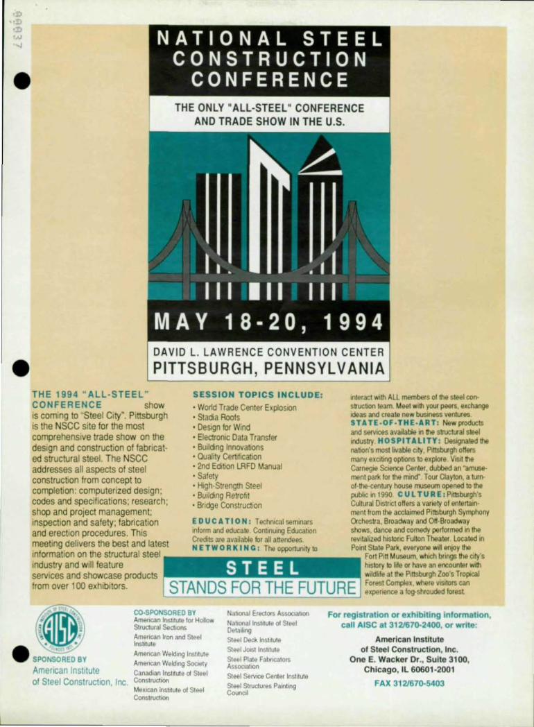
PITTSBURGH, PENNSYLVANIA THE 1994 " ALL -STEEL " CONFERENCE show IS coming to Steel City". Pittsburgh IS the NSCC site for the most comprehensive trade show on the design and construction of fabricated structural steel. The NSCC addresses all aspects of steel construction from concept to completion: computerized design; codes and specifications; research ; shop and project management; Inspection and safety; fabrication and erection procedures. This meeting delivers the best and latest Information on the structural steel Industry and will feature services and showcase products from over 100 exhibitors.
SESSION TOPICS INCLUDE:
• WoMd Trade Center ExplosIOn • Stada Rools • DeSign for Wind • ElectrOniC Data Transfer • Bulldng Innovabons • (}Jallty Certllicatlon • 2nd Edition LRFD Manual • Safety • High-Strength Steel • Bulldmg Retrofit • Bfldge ConstrucllOn
E D U C A TI 0 N: T echmcal semmars Inform and educate Contmulng Educallon Credits are available for all anendees N ETWO R K I NC: The opportuOlly 10
Interact WIth ALL members 01 the steel conslrucbOn te3m Mael wlih your p81fs. exchange Kieas and create new business ventures STATE .OF·THE-ART : NowproduclS and servICes available In h structlral sleet Industry H 0 S PITA II TY : Oostgnalild the natlOn's most lovable clly. f'lnsboxgh oHors many oXClUng optJOns to oxplofo VISIt the Carnegie Sc.ence Center, dubbed an "amusement park lor tho mind" Tour Clayton, a turnof the-century house ITlJSOlITl opened 10 the ""bhc ln t990 CUl TURE : PlitSburgh's Cultural Dlstnct offers a variety of entertainment from the acclaimed PIt1SbUigh Syn¢ony Or-ches~a. Broadway and OH-Broadway shows. dance and comedy performed In tho reVitalized hlSkHlc Fulton Theater Located In POint State Park, evoryone Will enJOY the
Fort Pin Museum. whICh bungs tho clly's hlslOry " ~fe Of have an encounter WI'" wildlife at the f'lnsboxgh Zoo's Tropocal Forest Co~x. where VlSItOrs can
..:.;...:..:::..;=-'--=-c..:.....:...:....:.=-'--=--'-=-c..:.=.J expenence a fog-shrouded IOfest
Nabonat Erectors AssocaatlOn
NalKlOaI InSllMe of Steel Dela~tng
For registration or exhibiting Information. call AtSC 8t 3t 21670-2400, or write:
American Institute ~ • SPONSORED BY
American Inslttute
CO·SPONSORED BY Ameucan ioslltute IOf Holow Struaural SedIOOS
American Iron and Sleel Insiliule
Amencan Welding Inslll\Ae AmerICan Welding SocUJly
Canadian Insillute 01 Sleel Construction
Steel Deck Insliluts Steel JotsllnSlrlUle
Sleel Plaia FabflC3IOfs Assocl3llOn Stool ServICe CenU!r In5111uI6 Sleel Structures Pallliing Co..,,,d
of Steel Construction. Inc. One E_ Wacker Dr., Suite 3tOO,
Chicago, IL 60601 -2001
of Steel Construction. Inc. MelCtCan Insiliute 01 Sleel Const~1On
FAX 3121670-5403

Erection And • Constructability Issues For
Long-Span Roofs
Figure 1 (top): The Fargodome. The 200-{t. x 320-{t. section in the center was lifted from the ground to its final position in one day.
Figure 2 (above): San Jose Arena. During the erection of the roaf space frame structural steel was shored to the arena floor at every third panel point.
18 1 Modern Steel Construction I February 1994
A look at lessons
learned on a series of
long-span construction
projects By Jack Petersen, P oE.
The complexities in vol ved in designing and con
structing long- s pan roof structures create unique problems and challenges_ As a result, different approaches to these projects are needed. Specifically, engineers need to an t icipate and accommodate erection problems_
Erection Procedure
•
The erection scheme used to construct long-span roofs on buildings will often determine if a project will be successful. The demands of roof construction may dictate access to the site and influence the project sched- • ule. It may be impossible for

•
•
•
other trades to continue working below while erection is in progress. A creative scheme, which addresses t h e special problems of a long-span structure, may result in a competitive edge to the bidding contractor.
When the contractor for a long-span roof is selected via the bid process, the EOR must define a reasonable, buildable erection scheme on the drawings as a common basis for bidding. In this case, the EOR must make assumptions regarding the erection procedure with limited knowledge of construction issues. These issues may include construction sequence, site constraints , coordination of temporary supports , and site access . When the Design-Build method is used to retain the project team, the EOR may have considerable input from the contractor during design on these issues.
The erection scheme shown on the construction documents must clearly communicate the basis for the EOR's design while maintaining flexibility for the contractor to change or improve it. It must define what factors the EOR has considered in his design. In addition to design information required on typical steel structures, the contract documents must define locations and extent of assumed temporary supports, lateral bracing at intermediate stages, splices and cambers. For two-way systems, the distribution of dead load in the structure results from the erection sequence. For such structures, final member sizes are dependant on the sequence of erection, therefore, the sequence must be defined to a llow the contractor to evaluate steel quantities.
Assigning Responsibility The EOR must also clearly
define what he has and has not designed and assign appropriate responsibility to the Contractors' Engineer. In typical long-span roofs, these topics might include:
• Design of shori ng towers, work platforms, and their foun-
Figure 3 (top): AlamoDome. The primary trusses were designed to be constructed on false work and lifted by a single crane at each end.
Figure 4 (aboue): Currigan Hall. The entire roof space frame was constructed on the conuention floor and jacked into place in sections.
Modern Steel Construction I February 1994 / 19
WE'RE SENDING OUT
GOOD VIBRATIONS.
Get the new computer vibration analysis for steel joist concrete slab floors .
Now you can do In minutes what used to lake hours. The new
(]
computer vlbrallon . . analysIs for floor . systems emploYing . sleel JOlsVconcrete
. .' slab floor constructJon leis you ..
• calculale Irequency and amplitude resulting from tranSient vibration caused by human activity on JOist-concrete floors
• perform vanous "what-I'" scenanos-vanatlOO In slab thICk· ness, concrete strength, JOIst Size, ""st spacing. lloor deck,ng. live and dead loads and span lengths
• venfy your own calculations
• handles up to 100 loot spans
The program IS available on 51/. and 31/2 Inch disks. IS IBM PC compatible and comes WIth a comprehensive 58-page user's manual. And at Just S125 00. th,s program pays lor ,lsell after Just one proJect. So filt Oul the coupon to order this lime-saVing program today _---I Please send me
program(s) al $12500 each In::Iudes PO&Iage
""'-' AllOAOEAS
MUST BE PREPAID
DIsk Size 3"'2' 51/4'
Total Aemlnance US CUnency Only
---COy Stal. ZIP
Mall to Managing Director DIY A· I
~ Steel JoIsllnslllute ~ 1205 48th Avenue North
Myrtle Beach. SC 29577
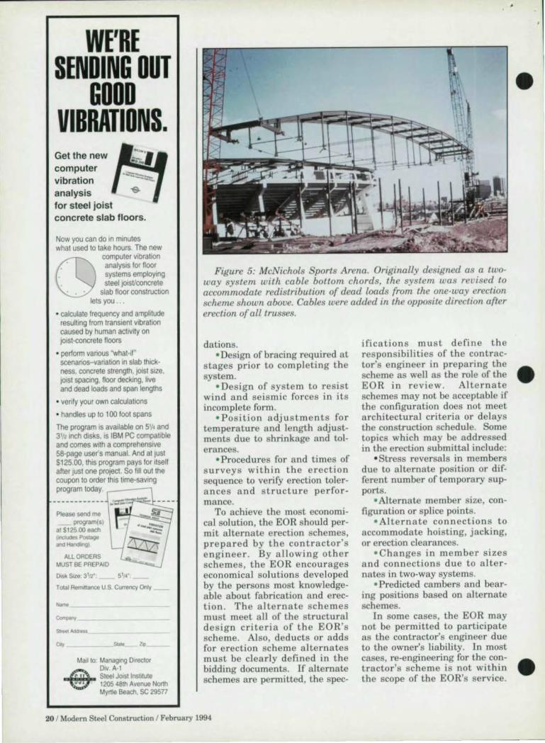
Figure 5: McNichols Sports Arena. Originally designed as a two· way system with cable bottom chords, the system was revised to accommodate redistribution of dead loads from the one-way erection scheme shown above. Cables were added in the opposite direction after erection of all trusses.
dations. ' Design of bracing required at
stages prior to completing the system.
• Design of system to resist wind and se is mic forces in its incomplete form.
• Positio n adjustments for temperature and length adjustments due to shrinkage and tolerances.
• P rocedures for and times of su rveys within the erection sequence to verify erection tolerances and structure pe rfor mance.
To achieve the most economical solution, the EOR should permit alternate erection schemes, prepared by the contractor's e nginee r . By allowing other schemes, the EOR encourages economica l solu tions deve loped by the persons most knowledgeable about fabrication and erection. The a lternate schemes must meet all of the structural design cri teria of the EOR's scheme. Also, deducts or adds for erection scheme a lternates must be clearly defi ned in the bidding documents. If alternate schemes are permitted, the spec-
ifications must define the responsibilities of the contractor's engineer in preparing the scheme as well as the role of the EOR in review . Alternate schemes may not be acceptable if the configuration does not meet architectural criteria or de lays the construction schedule. Some topics which may be addressed in the erection submittal include:
' Stress reversa ls in members due to alternate position or different number of temporary supports .
• Alternate member size, configuration or splice points.
' Alternate connect ion s to accommodate hoisting, jacking, or erection clearances.
' Changes in member sizes a nd connections due to a lternates in two-way systems.
• Predicted cambers and bearing positions based on a lternate schemes.
In some cases, the EOR may not be permitted to participate as the contractor's engineer due to the owner's liability. In most cases, re-engineering for the contractor's scheme is not with in the scope of the EOR's service.
20 I Modem Steel Construction I February 1994
•
•
•
•
•
•
•
Requiring an erection submittal in the specifications is an excellent method of communicating the assumptions of design between the EOR and the Contractor's Engineer. The responsibilities of the contractor 's engineer can be clearly defined, as well as the extent of review by the EOR.
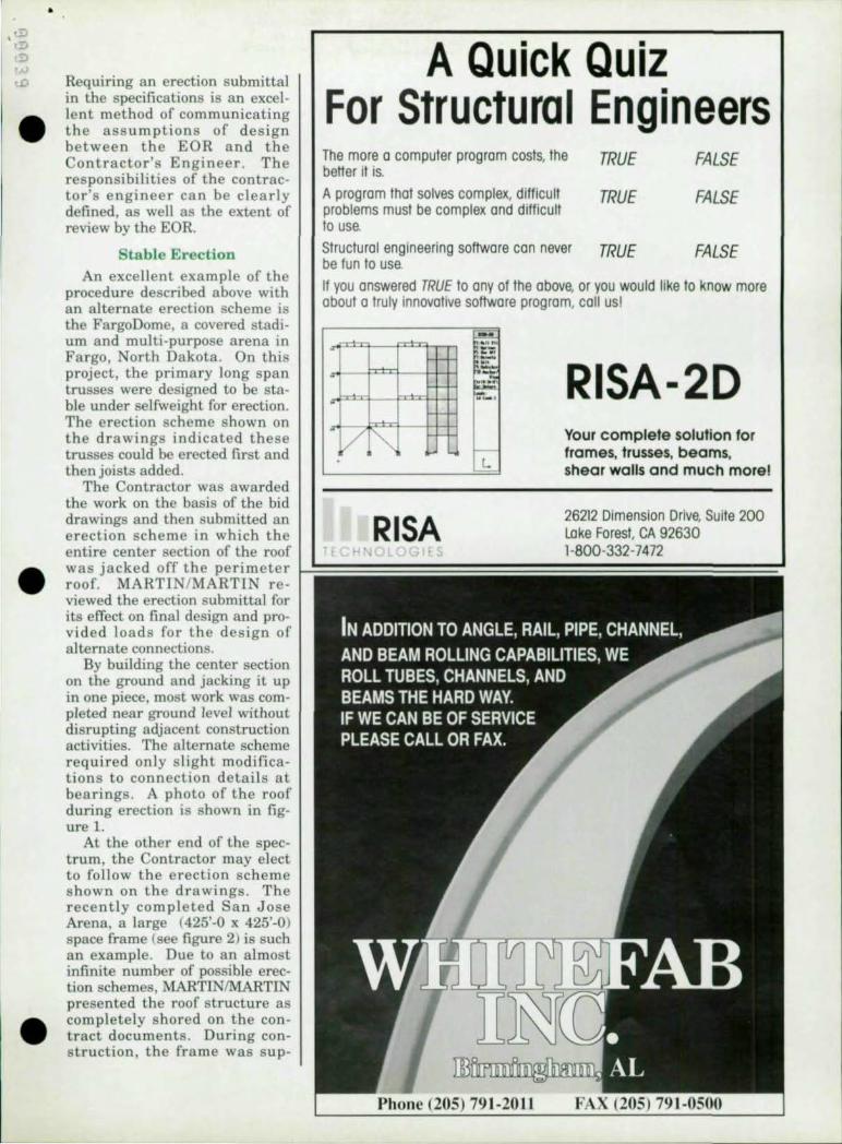
Stable Erection An excellent example of the
procedure described above with an alternate erection scheme is the FargoDome, a covered stadium and multi-purpose arena in Fargo, North Dakota. On this project, the primary long span trusses were designed to be stable under selfweight for erection. The erection scheme shown on the drawings indicated these trusses could be erected first and then joists added.
The Contractor was awarded the work on the basis of the bid drawings and then submitted an erection scheme in which the entire center section of the roof
A Quick Quiz For Structural Engineers The more 0 computer program costs, the better it is.
TRUE FALSE
A program that solves complex, difficult problems must be complex and difficult to use.
TRUE FALSE
Structural engineering software can never TRUE FALSE be fun to use. II you answered TRUE to any 01 the above, or you would like to know more about a truly innovative software program, call us!
-
"/ ~
RISA
L
RISA-2D Your complete solullon for frames, trusses, beams, shear wails and much more!
26212 Dimension Drive, Suite 200 Lake Forest, CA 92630 1-800-332-7472
was jacked off the peri meter 12=======::::::::::::::::::::==============' roof. MARTIN/MARTIN reviewed the erection submittal for its efTect on final design and provided lo ads for the design of alternate connections.
By building the center section on the ground and jacking it up in one piece, most work was completed near ground level without disrupting adjacent construction activities. The alternate scheme required only s light modifications to connection details at bearings. A photo of the roof during erection is shown in figure l.
At the other end of the spectrum, the Contractor may elect to follow the erection scheme s hown on the drawings. The recently completed San Jose Arena, a large (425'-0 x 425'-0) space frame (see figure 2) is such an example. Due to an almost infinite number of possible erection schemes, MARTINIMARTIN presented the roof structure as completely shored on the contract documents. During construction, the frame was sup-
79 1-2011

ported at every third panel and jacked down as a complete structure.
Structural System Design Long-span structures have a
number of unique problems related to erection which innuence the selection and economics of the structural system . For these buildings, system selection based on weight may not yield the most economical or constructable design. AJ'chitectural constraints may eliminate some systems from consideration. If the EOR is defining an erection procedure on the bid documents, s pecial con s iderations of constructability must be addressed.
.'
. , ,
/ /'"
.--0
--<>
0
0
0
0
0
0
'--0
----0
The erection of s pans in excess of 300-ft. typically require some in-place assembly of structural steel. Often times, this work is performed on platforms of limited size , far above the ground surface. Lifting and positioning of each piece of steel requires a large crane due to reach and accessibility considerations. For safety reasons, construction by other trades below is often interrupted while erection proceeds. Delivery of material and/or access for cranes may dictate the sequence of substructure construction. These factors significantly affect project schedule and may innuence overall project economy.
jl 11 !!~
To alleviate the problems due to in-place assembly, the structure may be designed to maximize shop fabrication and preassembly. The details of the structure should specify shop welds or bolts for the largest sections which may be shipped or lifted on the job. An example of designing to lift capacity is the AlamoDome in San Antonio , Texas (figure 3). In this project the primary trusses, spanning 400 ft., were designed based on the hoisting capacity of one cl'ane lifting at each end. If a contractor is on board during the design pha se , th e engineer should utilize his knowledge of site constraints, lifting capacity, and construction sequence in
developing details. Connections which can be constructed in the shop may offer better thermal control, improved welding position , and improved access for welding inspection by the testing agency over those done in the field. Any problems arising from distortion and weld shrinkage can be identified and corrected prior to erection.
Pre-assembly of large sections on the ground or on low level falsework can greatly improve system economy. Individual pieces on such sections may be lifted by small cranes or lifts reducing demand on large equipment. Construction of access platforms may be greatly simplified near ground level and exposure of workers reduced. Ideally,
22 1 Modem Steel Construction I February 1994
pre-assembled sections should be designed to rest On bearing seats at erection. Design should allow them to be tied back and stabilized with adjustable connections using erection bolts. Final connections, after alignment and positioning, may be welded or bolted consistent with detailing on the project.
Pre-Assembling An Entire Roof
Extending the pre-assembly concept to incorporate the entire roof is possible. An example of such a structure is Currigan Hall in Denver, Colorado (figure 4). On this project , the roof space frame was constructed on the convention hall noor with prefabricated elements and "uni-
•
•
•
•
•
•
•
,,"OTE. ANGLES, lS 12K6 • suor "SSE'" Y SHALl BE
SHPPED TO THe SIT[ If-j Qt.E PlEa: .t HElD
f"ft I,lLY IN CONTACT BY C~TR DESIGNED JIG
OUR lifG /'wS'ALLAlJON
(2) "' '''();I ".E 80L T IN 1 1/2-vtRT Slomo Ha..£S -AO..1.l5T U TO PQSjl1QN
SHOW'i .. TIGH TEN
... eX8Kl/2K,'-6 WI snFf PL f A [NO
o.or ..", 0"," >-n--.J.-' s·
PROVIDE ASS[i.4BLY SHOwtl • 8"-0 D.C:t: - 4-THUS 8~ U. TRUSS BRC I ~ ZONES HOl!O
"" PlM
SlJO( BRC AS5O,jBl Y
WELD ENOS nRST ST"CCER SIDES/END TO UMIT OISTORllON
BOT fL.ANGE Of RING eM
GR' ''I O FUJSH ,&-",-< 0 TOP SURfACE
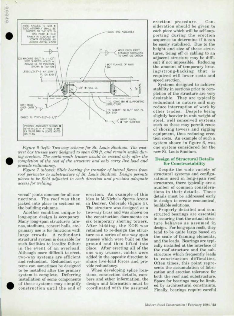
Figure 6 ([eft): Two·way scheme for St. Louis Stadium. The east· west box trusses were designed to span 600 ft. and remain stable duro ing erection. The north·south trusses would be erected only after the completion of the rest of the structure and only carry live load and provide redundancy.
Figure 7 (above): Slide bearing for transfer of lateral forces from roof perimeter to substructure of St. Louis Stadium. Design permits pieces to be field adjusted in each direction and provides adequate access for welding.
versal" joints common for all con· nections . The roof was then jacked into place in sections on the building columns.
Another condition unique to long·span design is occupancy. Many long·span structure's (are· nas, stadiums, concert halls, etc.) primary use is for functions with large crowds. A redundant structural system is desirable for such facilities to localize failure in the event of an overload . Although more difficult to erect, two· way systems are efficient and redundant. Redundant sys· terns can sometimes be designed to be installed after the primary system is complete . Deferring installation of some components of these sys tems may simplify construction until the end of
erection . An example of this idea is McNichols Sports Arena in Denver, Colorado (figure 5). The structure was designed as a two· way truss and was shown on the construction documents on six temporary horin g towers. After bidding, the EOR was retained to re·design the struc· ture as a series of one way span trusses which were built on the ground and then lifted into place . After erecting all of the one way trusses , cables were added in the opposite direction to share live·load forces and pro· vide redundancy.
When developing splice loca· tions, connection details , cambers and other information , the design and fabrication must be coordinated with the assumed
erection procedure. Con· sideration should be given to each piece which will be self·sup. porting during the erection sequence to determine if it can be easily stabilized. Due to the height and size of these struc· tures, tieing ofT or cabling to an adjacent structure may be diffi· cult if not impossible. Reducing the amount of temporary brac· ing/strong·backing that is required will lower costs and speed erection.
Systems designed to achieve stability in sections prior to com· pletion of the structure are very desirable. They are typically redundant in nature and may reduce interruption of work by other trades . De spite being slightly heavier in unit weight of steel, well conceived systems such as these may permit reuse of shoring towers and rigging equipment, thus reducing erec· tion costs. An example of such a system shown in figure 6, was one system cons idered for the new St. Louis Stadium.
Design of Structural Details for Constructability
Despite the wide variety of structural systems and configu. rations used in long·span roof structures, there typically are a number of common consid ra· tions in their details . These details must be addressed early in design to create economical, buildable solutions.
Properly detailed and con· structed bearings are essential in assuri ng that the actual struc· ture behaves as assumed in design. For long·span roofs, they tend to be quite large based on the scale of framing elements , and the loads. Bearings are typi· cally installed at the interface of the roof structure and the sub· structure which frequently leads to construction difficulties . Often times, this point repre· sents the accumulation of fabri· cation and erection tolerance for both the roof and substructure. Space for bearing may be limit· ed by architectural constraints. Finally, bearings require careful
Modem Steel Construction I February 1994 / 23
-_._--------
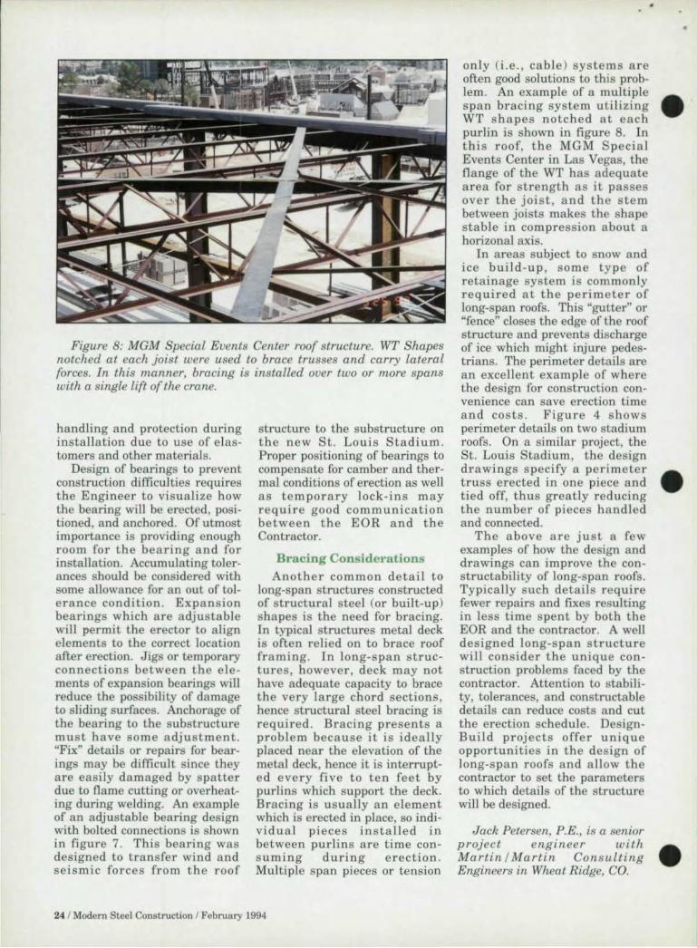
Figure 8: MGM Special Events Center roof structure. WT Shapes notched at each joist were used to brace trusses and carry lateral forces. In this lIlanner, bracing is installed over two or 1Il0re spans with a single lift of the crane.
handling and protection during installation due to use of e lastomers and other materials.
Design of bearings to prevent construction difficulties ,·equi,·es the Engineer to visualize how the bearing will be erected, positioned, and anchored. Of utmost importance is providing enough room for the bearing and for installation. Accumulating tolerances should be considered with some allowance for an out of tolerance condition. Expansion bearings which are adjustable will permit the erector to align elements to the correct location after erection. Jigs or temporary connections between the elements of expansion bearings will reduce the possibility of damage to sliding surfaces. Anchorage of the bearing to the substructure must have some adjustment. "Fix" details or repairs for bearings may be difficult since they are easily damaged by spatter due to flame cutting or overheating dw·ing welding. An example of an adjustable bearing design with bolted connections is shown in figure 7. This bearing was designed to transfer wind and seismic forces from the roof
structure to the substructure on the new St. Louis Stadium. Proper positioning of bearings to compensate for camber and thermal conditions of erection as well as temporary lock -ins may require good communication between the EOR and the Contractor.
Bracing Considerations Another common detail to
long-span structures constructed of structural steel (or built-up) shapes is the need for bracing. In typical structures metal deck is often relied on to brace roof framing. In long-span structures, however, deck may not have adequate capacity to brace the very large chord sections, hence structural steel bracing is required. Bracing presents a problem because it is ideally placed near the elevation of the metal deck, hence it is interrupted every fi ve to ten feet by purlins which support the deck. Bracing is usually an e lement which is erected in place, so individual pieces installed in between purlins are time consumi ng during erection. Multiple span pieces or tension
24 / Modern Steel Construction / February 1994
only (i.e., cable ) systems are often good solutions to this problem. An example of a multiple span bracing system utilizing • WT s h apes notched at each purlin is shown in figure 8. In this roof, the MGM Specia l Events Center in Las Vegas, the flange of the WT has adequate area for strength as it passes over the joist, and the stem between joists makes the shape stable in compression about a horizonal axis.
In areas subject to snow and ice build-up , some type of retainage system is common ly required at the perimeter of long-span roofs. This "gutter" Or "fence" closes the edge of the roof structure and prevents discharge of ice which might injure pedestrians. The perimeter details are an exce llent example of where the design for construction convenience can save erection time and costs. Figure 4 s how s perimeter details on two stadium roofs. On a similar project, the St. Louis Stadium, the design drawings specify a perimeter • truss erected in one piece and tied off, thus greatly reducing the number of pieces handled and connected.
The above are just a few examples of how the design and drawings can improve the constructability of long-span roofs. Typically such details require fewer repairs and fixes resulting in less time spent by both the EOR and the contractor. A well designed long-span structure will consider the unique construction problems faced by the contractor. Attention to stability, tolerances, and constructable details can reduce costs and cut the erection schedule. DesignBuild projects offer unique opportunities in the des ign of long-span roofs and allow the contractor to set the parameters to which details of the structure will be designed.
Jack Petersen, P.E., is a senior projec t engineer With . Martin i Martin Consulting Engineers in Wheat Ridge, CO.

33'2 Parentlll ,\I t' F Rwht'tj,.rJ. \J 07073
• very easy 10 learn and use, become a prockKIive user in just one day extremely last, shortens the cOl1(epl through design cycle most powerful on PC plolform · 3D FEM, buckling, nonlineor, P-deita dynamic, 3D moving loads, parametric structures, phose constructions, US and' foreign codes
• buy the power you need, storts from $495 version · 150 node/3D plus plate elements • easy payment plans for 1500 and 32500 node versions • no risk, 30 day money bock guarantee
See for yourself. Have fun. Any questions? C" us.
II ~runswith NetWare
0.. T...., Or '1 NO'01tIIm ..... no,. I
....... 'fI'tII ...... 1O .... -DEMO AVAIlABLE (WO KING VfiSlON Of PIIOGRAM AND PRERECORDED EXAMPLES) OVER 1200 USERS WORLDWIDE. fOR MORE INFORMATION CALL 201·438-4915 OR FAX TO 201·438·7058 r--------------------------------------------------------------------, : 110 Home: I I =- (ompony: I I Addr",,: Slole Zip :
W: ~ I
10m: .J Ilructurol engineer, .J orchilect, .J educolor, .J dealer, .J olher: : .J Pleose have 0 product Ipeciol"1 call me .J Pleose send more informolion f .J Pleose send working demo verlion (limiled 10 20 elemenll ond 30 nodes I, wilh recorded macros of real delign exomplel. Endosed il 0 check for 525 I (plus applicable Tax in NJ and NYI. I have a Iyslem equal 10 or be"er Ihon 386SX wilh molh coprocesror, 4 MB RAM, 20 MB of free dilk Ipoce,VGA monitor. I MelTorolf, 332 Palerson Avenue, E. Rutherford, NJ 07073. Tel 201 438·4915, Fax 201 438·7058. I L __________________________________________________ ~
UK • Germany • Italy • Belgium • Spain • Portugal • France • Bralil • Luxembourg • Poland • Jordon • Moro((o

Arched chord JOistS lop [he Amt"dls Ilall, iml'TllDuunal Concourse, Ilansfield Atlantll hlll'nUitional Air/x,,"(
-- -- ---------------- -
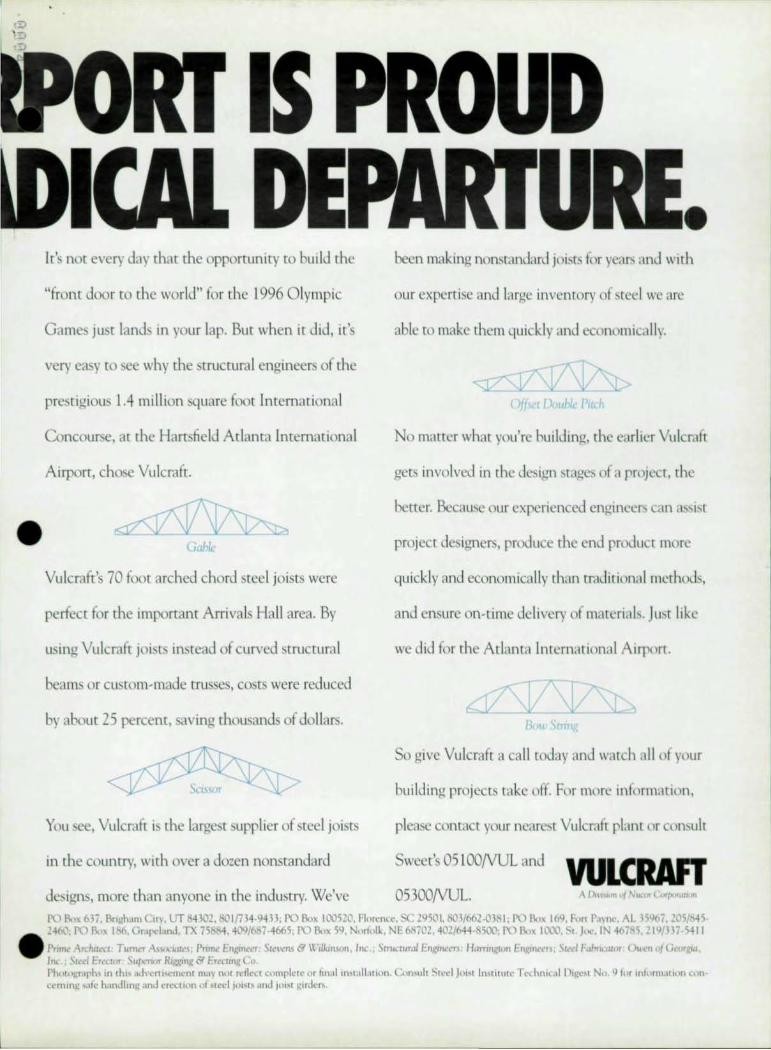
It's not every day that the opportuniry to bui ld the been making nonstandard joists for ycar.. ,md with
"front door to the world" for the 1996 O lympic our expert ise and largc inventory of tcel we are
Games just lands in your lap. But when it did, it's able to make them quick ly and economically.
very easy to see why the strucUiral engineers of the
prestigious 1.4 mi ll ion square foot Internationa l ()! I), Ir !in
oncourse, at the Hartsfield Atlanta International o matter what you're hui lding, the earlier Vulcraft
Airport, chose Vulcraft. gets involved in the design stages of a project, the
better. Because our experienced engineer, can assist • project designers, produce the end product more
Vulcraft's 70 foot arched chord steel joists were qu ick ly and economica lly than traditional mcthods,
perfect for the important Arrivals Hall area. By and ensure on-time delivery of ma[(~ria l . Just like
using Vulcraft joists instead of curved structural we did for the Atlanta Internationa l Airport.
beams or custom-made trusses, costs were reduced
by about 25 percent, saving thousands of dollars.
So give Vulcraft a call wday and watch all of your
bui lding projects takc off. For more infmmarion,
You see, Vulcraft is the largest supplier of steel joists please contact your nearest Vulcraft plant or cnn!>ult
in the country, with over a dozen nonstandard Sweet' OS I OO/VUL and WLCHAn designs, more than anyone in the industry. We've 05300/VUL. 1'1..) )\''1; 63i'. Bnuh.un CU\.lJf 84302. MOln14·94H; Pt.) Bc.,x 100520. Flureno,·. SC 29501. HOJ/661·0JBI. PO J\.,)( 16Q. Fun r.l,n~·. ,.\L ~~I,I('i. 205/MS· 246l\ 1'\.) B.,lX I~. Gr.lf'l'bnd. TX 75~. 409/~7·4665; PO 110)( 59, NmfoH" NE ~70l. 402l644·h5(X'1; 1'\.) 1\.;" 11.,\.\1, St. Jl'C. IN 4(17HS, 21""H7-5411
• Prone ,,,,,.dut~(I, Tumt'r A~_..,~'wLt'S; Pmne Engmel"" Slel'l'tlS & \V,lkin$(II}, II",; )tnKwmf EnJ::"1I4'l'Tl l-famnRwll f:'nXIlk'eu; \{I!el F,J,r"lUn1' (>U ... n IIJ (jI."CITgw, /Tko' Sled Erector: SU(k't'lrrr R,ggtll,l: & ErccunR Co, rh{'I.~""lrh~ In thl' ,I~k ... nl'('m~'n( rna) nl11 rdll'ct cnmplclc or hn'lllll'(,lll,IIIOIl. CAlll,u l, Sll· ... 1 Jl)'" In~lltll ll' Tl'~ hnIL11 1 )L~~" Nt), I.) j,'r ,n!l,nn,tlilln lon u'mmg .... tfe h,mJIlIlg J.nJ crccUtltl of ~(cd J{)"I' ,mtl JOISI gm.1cf'I.

Meeting Vertical And Horizontal Constraints
A new generation of vert ica lly stacked convention centers fi t into urban cores without destroying the c ity grid
By J ohn C. Alfa no, Greg M. Detmer, AlA, Bria n T. Eaton, P .E., Dona ld I. Grinbe rg, AlA,
and John T. Holcomb
Unlike its sprawling predecessors, the Rhode Island Convention Center is a
ve r t ica ll y stacked convention center whose design was dictated by a tight site and a restricted urban location.
The five-level structure had to meet depth restrictions dictated by the water table, height restrictions imposed by the ity of Providence, and horizontal space restrictions resulting from
•
the tight site in the heart of downtown Providence at the • intersection of two heavily trav-
Site considerations played a key role in the design of the Providence Convention Center.
28 / Modem Steel Construction I February 1994
ell ed streets and immediately adjacent to the existing 'VIC
Center. In addition, the archi-tects had to meet Capital Center District design criteria. And finally, the design needed to take into account functional and cost considerations that made it desirable to minimize f1oorto-noor heights without compromising t he req u ired vertical clearances in the key leasable spaces.
F'rom bottom to top the 365,000-sq.-ft. structure includes: three levels (one above, one at, and one below grade) of parking for 720 cars; a 100,000-sq.-fl., 30-fl.-high exhibition hall on the next level; and above that a 20,000-sq.-ft., 25-ft.-high ballroom, 18 meeti ng rooms, and a full-service kitchen, which can pl'oduce 5,000 meals per day.
The building was the result of a developer-builder-architect competition won by developer MetroPartners, Providence, architect HNTB, Boston, and •

•
•
•
..... - n -
CROSS-SECTION TIflU PROVIlENCE CONVENTION CENTER
construction manager Gilbane Building Company, Providence. HNTB's structural consultant on the project was Boston-based Zaldastani Associates.
Vertical Requirements
Because the lOO,OOO-sq.-ft. exhibition hall could not fit on the ground level without impacting city streets and adjacent hotel and parking garage access, the designers placed it 25 ft. above ground and extended it over one of the streets. This vertically stacked design required that the structure support large loads using long spans above grade. To accomodate the design, a construction plan was devel oped based on erecting the center in five 120-ft. vertical sections from the ground right up to the roof. Working from west to east, the steel erectors finished one section at a time to allow continuous crane access.
Beneath the exhibition hall is a three-level garage. After examaning a variety of options, the design team chose a hybrid form of construction with steel building columns and precast GO-ft. double tee planks. The combination of precast pieces and steel columns made for a very economical design, especially in light of the unusual site and tight construction schedule. Also, the sep-
II
Modern Steel ConstruCllon I February 1994 / 29

A new addition to the Design Advisor family:
FLOOR VIBRATIONS An Expert System to Help the Designer
Six Tolerance Criteria to Choose From: Murray - - - - - - - - - - - - - - - - - Office/ResldentiaJ Environments
Modified Relher·Meister - - - - - - - - - Office/Residential Environments
Wiss-Parmelee - - - - - - - - - - - - •. Office/Residential Environments
Canadian Standards Assodation - - - - - Walking Vibrations
8lingwood and Talli" - - - - - - - - - - Commercial Environments
Allen E Aerobics } ~ Offices Dandng With Residential Uvely Concert Dining Sports Event Weightlifting
ALL FLOOR FRAMING Hot Rolled Sections, Jolsu, ilnd Built-up
ei"'~;:~::~~~::"_ Graphics Dllpltly
Oefilult Ta bles (or Jobs or u Standud Expert Advice for All Input ilnd Inte rpretiltlon
Just Press (Fl )
To order send P.O., check or money order for $250 plus $10 S&H to:
Structural Engineers Inc. 537 Wisteria Drive Radford VA 24141
Voice: (703) 731 ·3330 FAX: (703) 639·0713
LIJ o Z LIJ
Site licenses are available
FROM
1I0UNDO Model RIIS",I/lnl WI1 x 6JMb<om 'he 'hardway'.
AS GOOD AS YOU'VE HEARD! 15 Models
from 2 x 2 x 5/16" to 10 x 10 x 1".
Fully hydraulic guide rolls. CNC optional.
Box 2193
COmEQ Baltimore, MO 21203 ,inC. Phone: (410) 325,7900 Fax: (410) 325,1025
arate steel perimeter beams and columns for the garage struc· ture, together with a center expansion joint, meant th e • garage could expand and con-tract independently under the e!Tects of ambient temperature changes.
Since the center was built in vertical segments, the coordination of fabrication, shipment and erection of the various structural components was critical to the construction schedule. Therefore, to promot.e efficiency and control, the production and erection of the precast tees was made part of the fabricator's contract. Since each tee had to go in sequentially and sinc the next level of structural steel for the building segment followed d irectly behind, one missed tee delivery would have had a serious impact on !.he erection process. The pre· cast t.ees are supported by paired W21x83 steel beams. All of the steel for this project was A572 Grade 50.
To minimize the elevation of the exhibition hall above, the garage was designed with a tight • Ooor-to-Ooor height. In addition, there was a restriction to the thickness of the Ooor sandwich of the exhibition hall immediately above the garage. The structural engineer devised a system of plat.e girders on each end of the grid lines, limited in depth to three fl., which were bolted and welded together to creat.e multi-ple continuous spans. The gird-ers sit on top of supporting columns, som" of which extend up through the building. The columns that terminate at this level have a cap plate designed like a bridge rocker bearing. These elements allow the shal-low plate girders to experience stress and deOection under large design loads without imparting bending moments to the columns, particularly those above, which are unbraced for 40 fl.
Contained in the Ooor sandwich between the upper level of the garage and the exhibit h,,11 • are the exibition ha ll concrete
•
•
•
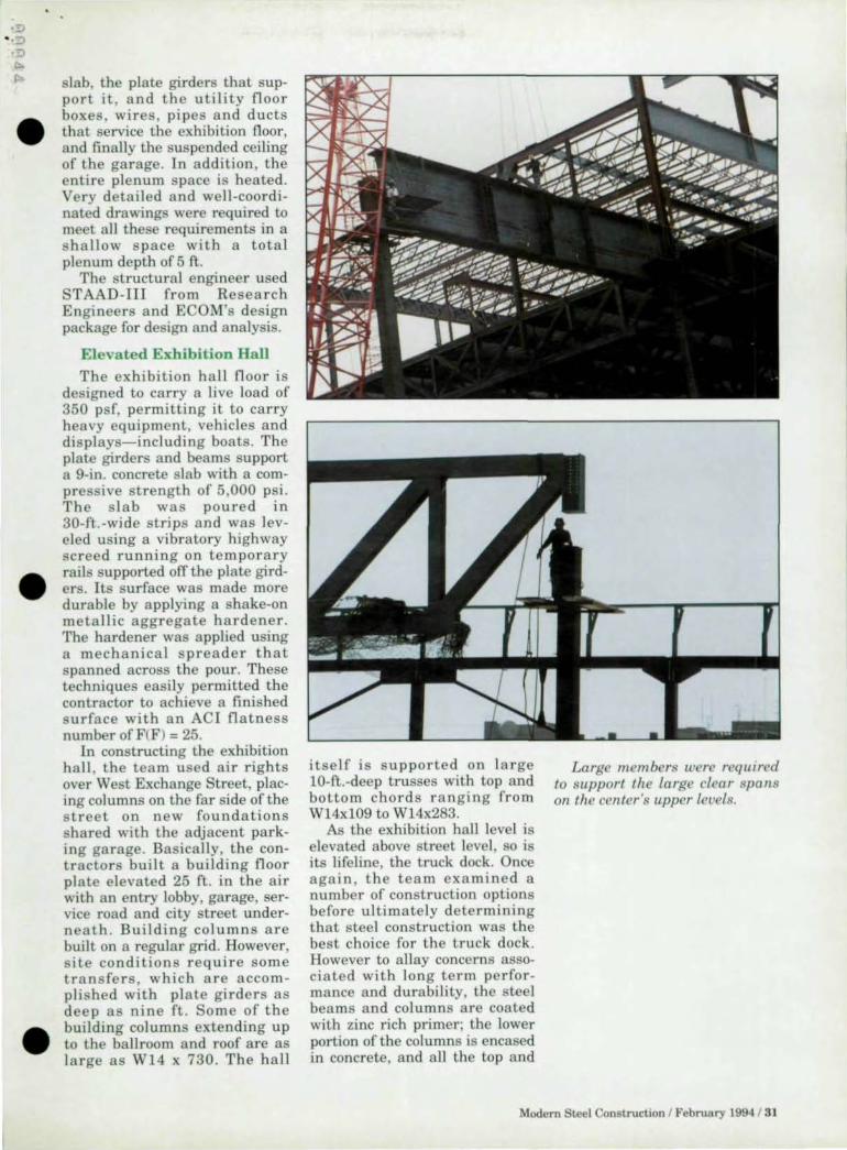
slab, the plate girders that support it, and the utility floor boxes, wires, pipes and ducts that service the exhibition floor, and finally the suspended ceiling of the garage. In addition, the entire plenum space is heated. Very detailed and well-coordinated drawings were required to meet all these requirements in a s hallow space with a total plenum depth of 5 ft.
The structural engineer used STAAD-III from Research Engineers and ECOM's design package for design and analysis.
Elevated Exhibition Hall The exhibition hall floor is
designed to carry a live load of 350 psf, permitting it to carry heavy equipment, vehicles and displays- including boats. The plate girders and beams support a 9-in. concrete slab with a compressive strength of 5,000 psi. The s lab was poured in 30-ft.-wide strips and was leveled using a vibratory highway screed running on temporary rails supported ofT the plate girders. Its surface was made more durable by applying a shake-on metallic aggregate hardener . The hardener was applied using a mechanical spreader that spanned across the pour. These techniques easily permitted the contractor to achieve a finished surface with an ACI flatness number of F(F) = 25.
In constructing the exhibition hall , the team used air rights over West Exchange Street, placing columns on the far side of the street on new foundations shared with the adjacent parking garage. Bas ically , the contractors built a building floor plate elevated 25 ft. in the air with an entry lobby, garage, service road and city street underneath . Building columns are built on a regular grid. However, site conditions require some transfers. which are accompli s hed with plate girders as deep as nine ft. Some of the building columns extending up to the ballroom and roof are as large as WI4 x 730. The hall
itself is supported on large IO-ft.-deep trusses with top and bottom chords ranging from W14x109 to W14x283.
As the exhibition hall level is elevated above street level, so is its lifeline, the truck dock. Once again, the team exa mined a number of construction options before ultimately determining that steel construction was the best choice for the truck dock. However to allay concerns associated with long term performance and durability, the steel beams and columns are coated with zinc rich primer; the lower portion of the columns is encased in concrete, and all the top and
Large tn.embers were required to support the large clear spalls on. the cellter's upper leuels.
Modern Steel Construction I February 1994 / 31

o
o (I
(0) .. o
..
,.,
"
'. c·
"
1 Exhibition Hall
.. I. o g
., "
Hall-"- HaIl'S'
bottom concrete reinforcing bars are epoxy coated. Metal deck between the beams is used only as a slab form. This nine-in. concrete slab has a compressive strength of 5,000 psi and contains a microsilica admixture for greater protection against moisture penetration. A first-class traffic-bearing membrane also was applied to the top surface of the slab. All steel beams are fireproofed, and the space below the slab and above the suspended ceiling is heated.
Special Considerations For Ballroom Design
The 20,000-sq.-ft. column-free ballroom, located above the exhibition hall, required special considerations. The floor, which is 70 ft . above street level, is designed to support a static live load of 150 psf, equivalent to the design load for libraries and warehouses. The team used 60-ft. and 120-ft. trusses to support the ballroom and to provide the clear spaces required for the
Hall-C
exhibition hall below. Because the exhibition hall height requirement was 30 clear ft. and it was desirable to minimize the vertical elevation of the ballroom level , the depth of the trusses could be only 10 ft.
Stiff 60-ft. span trusses with a natural frequency profile that is out of the range of rhythmic dances were used under the main ballroom, where a variety of functional uses and loading occur, and 120-ft. trusses were used to support the kitchen and meeting rooms that make up the balance of the floor.
The roof structure over the ballroom is a series of trusses, partially exposed to give an architectural treatment. Some have W14x233 top chords and W14x193 bottom chords, while others have IS-in. tees as a top chord with WlS bottom chords.The balance of the convention center roof consists of 120-ft.-long, custom-made steel joists. Since the ballroom itself can be subdivided into five
32 / Modern Steel Construction I February 1994
sma ller function spaces through the use of moveable partitions, the roof truss system was designed to support a suspended • track system for these partitions. Roof and floor deflections under potential live loads were coordinated with track and partition details to ensure proper opera-tion.
Exposed Steel Architecturally, a primary
vocabulary of the building is exposed steel: the trusses in the upper prefunction space; elements of the entry rotunda; and the front facade of the bui lding with 30-in .-deep beams and columns and two-in.-diameter rods as arch itectural cross bracing.
The architects considered var-ious options for the exterior treatment of the building, including the use of granite and masonry to wrap the stee l. However, it was decided to expose the structure of the upper portions of the building, thus achieving a desired layering and • transparency between the interi-or pre-function areas and the surrounding city. The exposed steel contrasts with the more trad iti ona l granite and brick used at the arcade's street level.
Exposing the structural steel within the ballroom itself carried the theme and transformed the ballroom into a unique space. A versatile and flexible indirect lighting system softly modulates the ceiling and partially exposed trusses, thereby creating an elegant and dramatic effect. The theme of exposed stee l is even carried through the custom fabricated stainless steel railings.
Complex Steel Erection Steel erection on this tight
site was a complex task. Prior to the start of design, the team met with fabricators and erectors to discuss how they would erect this building and how they would deliver the required truss-es to the site. It was at this point • that the scheme of constructing the building in vertical segments

•
•
was created. This method of construction had the advantage of providing a fast learning curve for the contractors, as building e r ect ion at each leve l was r e peated with each section. However, according to Lee Burneson, Gilbane superi ntendent/manger: "The most difficul t part of the construction occured as t he c rew met the s kewed angle created at the east end of the site.
"The last sections of the buildi ng to be erected were bou nded by the skewed property line of the site. This line of the s tructure ha d complex stee l connections for trusses and vertical bracing that had to tie into the mass of the already plumbed a nd erected structure.
U At the same ti me, there was less and less s ite avai lable for laydown. However, we sti ll had the benefit of our experience in erecting so much of the building
Instant Steel Information
Info on >leel publication; and software is only a phone call away with AISC's new Infomlation Fax Line.
Simply call 1-800-644-2400 from any pushbutton phone.
By following the brief instructions and pressing ju"t a few buttons on your phone. you can request information on: Manual; & Supplements; Specification; & Codes; Design Guides; Technical & Fabricator Publications: Conference Proceedings; and AISC Software.
CALL:
1-800-644-2400
from bottom to top a lready." Because of t he heavy trusses
75-ft. to 90-ft. in the air, the boom of the 300 ton crane was restricted in reach. To assist in truss erectio n , AISC-member Berlin Steel brought in a tower crane to work in tandem with the heavy crane.
Steel assembly was enhanced by the determination that the long-span t russes could be delive red to the s ite in one pi ece, greatly increasing qua lity control and reducing on-site staging requirements. At a nyone time, the steel contractor controlled 25-30% of the site, inc ludin g areas for lay down.
The variety in types, lengths and weights of steel framing elements on the project was careful ly planned by the erector, Berlin Steel. Assembly was further cha llenged by the spherical bearings at the bottom of many columns, which req uired tempo-
rary bracing until the major elements of the ballroom s uper structu re were in place .
Structural steel erection was the backbone of the construction schedule. Once the steel was set in pl ace, aligned, plumbed, bolted and welded, connections were inspected by a testing agency. Penetration welds were ultrasonically tested, a nd eve ry plate girder connection, t russ connection and bracing connection was tested.
John Alfano is a project execu· tive with Gilbane Building Company, Providence. Donald I. Grinberg and Greg M. Detmer are principal architects wit h HNTB , Boston. Brian T. Eaton, P.E., is an associate wit h Zaldastani Associates In c., Boston. John T. Holcomb is vice president of AlSC-member The Berlin Steel Company, Berlin, CT.
Over 30 Years Of Successful Construction
Dispute Resolution.
S incc the early 1960s, the registered professional engineers and consultanls of McDonough
Bolyard Peck have helped owncrs, contractors and attorneys successful ly resolve over one bill ion dollars in
• Proven, fo rensic approach to delays. impacts, acceleration, and inefficiency.
• Detailed research, articulate reports and testimony. ADR.
construction disputes. ... .... _ ... _
• $3 billion of collective r : I III Call today for a free
brochure .
construction field experience. c ons truction engineering
(703) 641-9088 'ICOO\OLGH BOLIARO PECK ' 82fiO "'LLO" OAKS CORP DRIIE. FAIRFAX. \ ., 22Ol1 • FAX.t70llb4t 8'65
Modern SLeel Construction I Pebruary 1994 133

Spanning Hockey1s Newest Pond
The roof of Anaheim's new arena clear spans 329-ft.-by-444-ft. to provide uninterrupted views
34 / Modern Steel Construction I February 1994
By Thomas Z. Sca rangello, P .E.
N othing's worse then paying lop-dollar for a sports ticket and then finding
yourself behind a pillar. To avoid any obstructions in the new stadium for the NHL's Mighty Ducks, the roof clear span stretches 329-ft.·by-444-ft. over a 19,200-seat arena known as "The Pond At Anaheim".
Clear-spanning such a large area required a complex structure. After careful consideration, a steel two-way tied :lrch system was selected. Advantages of the system in this application included:
1. Tied arches minimize outward thrust, and therefore eliminate the need for a peri meter ring to resist tension (as would be needed with untied arches) or compression (as would be required with air-supported and tensile structures). The roughly rectangular footprint, idea l for arena seating layouts, was not suitable for a round or oval tension or compression ring arou nd the roof edge.
2. Two-way spanning action accommodated the architectural intent of the project. To minimize the visual bulk of the project and the enclosed volume, the architect designed the roof with shallow edge depths and corners that were trimmed back to curves and then depressed as distinct "pie slices". Such special corner and edge conditions were easily accommodated by the two-way system selected. In contrast, one-way span systems are best suited for rectangu lar roof plates of uniform elevation.
•
•
•

•
•
•
3 . Trussed arch members offered both visual lightness for 3l'chitectural effect and physical lightness for shipping and handling.
4 . The trussed arch profile se lected has low arch profiles and sagged tension ties , minimizing roof height, visual bulk and enclosed volume without sacrificing overall structura l depth or obstructing sight lines.
5. Large, efficient structu ral depths were created by combining shallow, easily shi pped upper trusses with simple tension ties and queen posts.
6. Erection was straightforward and efficient by erecting primary trusses first and then dropping in secondary framing.
The roof structure uses six intersecting steel broken-back tied arch trusses to form the main roof frruning elements. The trusses are 12.5-ft. deep between chord centerlines and slope downward 28 ft. towards each end. The tension ties connect to truss bottom chord ends, and pitch downward an additional 10 ft. to central posts, creating an effective overall depth of approximately 50 ft. The typical busses have bottom chords ranging from W14x30 tn W14x43 and tnp chords ranging from W14x43 to W14x68.
Infill trusses, also 12.5-ft. deep, cover the central roof area by spanning between the main tied arch elements and the roof perimeter.
The "pie slice" sections at each corner of the roof are depressed 5 ft., but the interior view is unaffected as the radial trusses here are only 7.5' deep. Wide flange purlins on 15-ft. centers span between trusses and support the roof deck. The deck, supplemented by in-plane bracing elements, forms the roof diaphragm system.
All trusses have wide flange top and bottom chords, ties and support columns. The tension tie members range from W14x61 tn W14x176. Truss verticals, horizontal elements and bracing elements are double angles. To
1, ~ . .::
" ~'>" ~ ' -' 0
n 0 --rr.,,··,I., Of!'
r-~"--
~~ "; ;:'j 0 -, 1:#;1 ""'J' •• L ••• \ox""")
!! ./ :...--:- ' . I \ UJ :;11; I I :it -''I:::: . ,
'!It, ,.. ~ .. l . O""D" .~ ,
~E ~,,;. ~ .. il4- '-'. _1.<0>,'
"- ~.,. ' f> ' .. ~ : -
;, .. , -'- '.'-. " . .. '. • ~ 00' : ,1.- '0' v:.' . ~ .
I L~. . .', ., w
" ;.
~. . I . . .. "
.. .1 k .:
I
DETAIL @ S=CTION 8) , '. 1" 0' , .. I '.C·
DE-jA IL.. A I····~~I
~ .. .... ,,-.. I (/r~" ~ . C'OLII ..... t •• t •• ~1.., .... I(c. lol l~ . , T
"··1" " -0 ' ~' o' .•. " . ,'~
.' .... "' '11 '·0' ~'-o' .' " .,' . ... . '1'6 . '·0' ,'-0' .\ . .,. ,.;
.. ,4 ..... ~ · o· t·..,· " . ,..: •• oI~" 1'4 " -0' ,-0· "
., , ..... HH_ I~'.)" , '·ct , . ,.
"
N°-:cs:-, "0" _ ....................... ____ .. .,.. ......
· ....... ,....,. ~-~."''':>''+ , ".,...- ... ....,.~., . ., . "' ........ < ... -~---.. .--.. ~ ... - ..... ~ • ------ ..... - ....... • __ 110"1. 'f .... & ~ ~n-e. "~ __ oOT
., ~ .. , .. --.... .
facilitate sh ipping, the out-to·out depth of truss elements was limited tn 14 ft.
Roof Support Options
Even after the roof framing system was selected, important structural decisions remained. Because of its location between the stiff roof plane and t he stiff seating structure, the support system foJ' the long-span truss reactions plays an important role in proper seismic performance. Several options were eva luated for the roof support system.
Supporting the roof trusses
.< " 1 'L. -~-
~.~.c-;ION @
directly on a concrete superstructu r e by extending the perimeter concrete frame up 20 ft. was unacceptable because it would not satisfy zone 4 seismic ductility requirements . Also. it offered no abatement of seismic latera l loads as the 0.5 second period of th roof st ru cture essentially matched the concrete s uperstructure. And finally , it would have been cost-prohibitive: it carried a high cost of a "flying form" construction (about $700 per cu. yd. of concrete) and required rocker and slide bearings with an estimated cost of
Modern tee l Construction 1 February 1994 / 35
design requirements for base isolation mandated at that time by code and building officials, the • actual benefit would have been smaller. The cost of the base isolation bearings and associated detai ls would also have exceeded the savings from eliminating rocker and slide bearings.
$200,000 to accommodate thermal movements between the roof and the superstructure.
Base isolation also was evaluated and rejected. This system still required an extended con-
crete frame, but by increasing the roof structure's fundamental period to approximatley two seconds, it reduced seismic forces at the superstructure by approximately 60%. However, with the
The system finally developed incorporates steel to provide a longer roof period and beneficial ductility without requiring expensive framing or special bearings. Flexib le steel perimeter columns rise from the top of the upper concrete seating level, connecting to roof truss and mechanical mezzanine members to form truss girder frames. Other perimeter members connecting to the co lumns form a circumferential fram e . Both frame systems qualify a s Special Moment Resisting Space Frames (SMRSF) by code. Together they provide the ductility and inelas-
New! Single-angle connections, individual prices
CONXPRT Fast, accurate and fully documented connection design
The complete design of shear and moment connections and column stiffeners and doubters with the following features :
Based on the AISC Manual of Steel Construction and Volume II-Connections Combines the engineering knowledge and experience of respected fabricators and design engineers Menu driven with built-in shapes database
Complete documentation of all design checks
To order or for more information:
Phone: 312-670-2400
Information Fax Line: 800-644-2400
American Institute of Steel ConstructIOn One East Wacker Drive, Suite 3100 Chicago, illinois 60601 ·2001
36 1 Modern Sleel Construction I February 1994
Now order individual connections or entire modules!
...--~
Module I ASD, v2.0 (complete) . .• •...••...... $410 Double-Angle Connections ....... ..... ... .. ......................... $11 0 Single-Plate Connections ......... .... ..................... ....... ... $110 End-Plate Connections ............. .......................... .. ....... $11 0 Single-Angle Connections ............................ ....... ........ $110
Module I LRFD, v1 .0 (complete) ...•... .... ..•. ..•. $310 Double-Angle Connections, Single-Plate Connections. and Shear End-Plate Connec1ions
Module II ASD, v1.0 (complete) .............. .. .. .. $41 0 Directly Welded Flange Connections .................... ...... $110 Flange-Plated Connections ......................................... $110 Column Stiffening Design ........................................... $210

------------------------------------------------------
• tic energy dissipation capacity required to resist earthquake forces and deformations in seismic zone 4. This dual steel frame system increases the roof structure's fundamental period to 1.3 seconds, reduci ng superstructure seismic forces by 50 percent. Its inherent flexibility also accommodates thermal movement without rockers or slide bearings. The columns range from W14x132 to W14x193.
Another criitical element is the steel-to-concrete interface. A deceptively simple-looking baseplate and clip angle connection provides critical performance and efficient erection in an economica l manner. It acts as a fixed connection for low-level seismic events, but provides ductile, stab le energy-absorbing inelastic behavior during severe events. In addition to good performance , the incorporation of this "simpJe" connection provid-
ed erection tolerance and ease of assembly to help keep the project on schedule and under budget.
Roof Erection
The success of any long-span
offers a full line of computer programs specifically for the steel fabrication industry. Wouldn't you like to realize the benefits that our existing 400 customers have been enjoying over the past 10 years?
SSC's integrated family of computer programs includes: Estimating
Production Control Inventory Purchase Orders Combining
structu re hinges on its erection method. T he Anaheim Arena roof erection scheme used eight falsework towers, one at each tied arch intersection, to support the 29-ft.-by-144-ft. center box
Only $299°o ~;a,..
P.O. Box 19220, Roanoke, VA 24019 (703)362-9118 Automated Beam & Column Detailing
.800J776-9118 Call for a FREE demo disk!
Modern Steel Construction I February 1994 / 37

and the 150-ft.-long trusses that radiate from it.
The key ingredient of the erection procedure was the location of the central box truss and its shoring towers , which enabled the entire roof structure to be erected without negatively impacting the construction of the 600,OOO-sq.-ft. concrete seating bowl. The major components and the steps in the erection procedure are as follows:
1. Erection of eight shoring towers within the arena floor footprint, with the compression struts and connection hubs placed within the towers at the onset of steel construction.
2. Shop fabrication of the roof truss sections with a maximum depth of 14-ft. out-to-out to facilitate shipping.
3. Field assembly of the center box on the ground and its erection as a single 130-ton unit utilizing two Cranes.
4. Erection and field welding of the perimeter support columns and special ductile moment frame just ahead of the follow-up roof trusses.
5. Dual east-to-west erection of the tension ties between the end of the tie-trusses and the compression strut connection hubs.
6_ Erection and bolted connec-
38 1 Modern Sleel Construction I February 1994
tion of the tension ties between the end of the tie-trusses and the compression strut connection • hubs.
7. Follow-up placement of the 3-in. roof deck.
8. Lowering of the shores three inches to the liftofT position after the completion of all of the items above.
9. Bolting of the slip connection between the truss bottom chord, the mechanical mezzanine and the perimeter columns, which was incorporated to accept the dead load movement at these locations and therefore minimize any potential dead load bending moments in the columns. This made it possible to incorporate the truss-girder frames in the ToorS seismic resistance system, which enhanced the system 's overall performance.
With all of the roof elements in place, the shores were lowered the anticipated three inches to the lift-ofT position on June 17, 1992, on ly three months after the start of erection. This sched-ule permitted early completion of • the project.
Partnering A key to the success of the
project was the tremendous cooperation among all of the parties involved. From day one, a partnering approach from the top down was instituted. As a result, the owner, architect , general contractor and owner's general consultant all worked together and kept the $67 million arena project barreling along towards it completion on June 18, 1993.
Each month the principals from the owner (the City of Anaheim), the architect (HOK Sport), the general contractor (Huber Hunt Nichols), and the owner's representative (Turner Construction Co.), met to grade the job, resolve disputes before they became problems, and ease the channels of communication among all disciplines. The partners maintained continuous con-tact throughout the process and • even organized outings to base-ball games. Everyone has

, , "" )
"-
•
•
•
worked on good projects where there was a sense of everyone working together. However, on some projects-and especially on some public works projectsthere is often an adversarial relationship between the designers and constructors. Partnering ofTers a forum for problem solving before the lawyers get involved.
This spirit of cooperation also existed among the steel fabricator, steel erector and structural engineer Thornton-Tomasetti Engineers. Upon award of the steel contract, the fabricator, engineer and other members of the building team began intense
discussions on the most mcient and safest erect ion seq uence compatible with the entire construction process for the othe r portions of the building. Th e result was a 50-step, 30-page erection procedure prepared by the fabricator and reviewed and approved by ThorntonTomasetti.
As a result of the teamwork and design, the project was completed ahead of schedule and within budget.
Thomas Z. Scarangello, P.E., is a senior associate with Thornton-Tomasetti Engineers in New York.
Optimal Cutting
Program A computer program
to save you money
Optimize the cutting of structural shapes by linear nesting . For stock, ordered material or both .
Ca ll today ! for a free no obligation demo disk and our
special introductory price
COMPUTER DETAILING CORPORATIO
A servIce compa,,), for Steel Fabricators
80 Second Strcct PIke - # 10 Southampton, PA 18966
For the BEST in Bridge Software ...
~
Design o f Curved Girder Bridges
NEW FEA TURES: Live Load Distribution· Automat ic
(Longitudinal & Transverse) o Mesh Generation· Automatic ORating' Auto Rat ing Factors o Influence line Output
(From Influence Surlaces) o Metric Conversion o Uses AASHTO 15th Edition
Lease or License Free Trial ... o Timesharing FUlL Pr_am!
MERLIN DASH TRAP OrIl 'lIn" "'1181,..1, 01 TNt. Rlbnlllftd 'tNl (t" de, 1rid9l1 Au",i, 'NIl".
AASHTO · u... Hew IStll Ed 0 Continuous to 6-spar.1 o FHWA · Endorsed ,nd lJMd by PrtSlressed Trusses ODOrs · UIed by 35 StJItI 0 Cable MembeB o Design -Colt ()sII'mQ'ed J Design & Rehab o Fnendly · MenIrOnYtn InplJ ':l AASHTO and II
Gr3(lhK:s Display 01 Output Vehides 10 20 Axles o Output Repon Selection 0 Autl cnnptOl)tIllN o Ouali ty and Performance Opera 1'9 & Post~ laid
Availablo Exclusivoly Thru:
OPTI-MATE INC . po. BOl9091, Dept A, Bethletem. PA 18018
(610) 867-4077
Modern Steel Construction 1 February 199·1/ 39

Cost-Effective Energy • Dissipating Connections
Slotted Bolted Connections show promise of becoming an inexpensive, easily designed method of energy
dissipation in seismic areas
OUTER .. : PLATE
: ... 314" DIAMETER A325 BOLT WI on UNDER HEAD STANDARD HARDENED
F 2
(AND OPTIONAL BELLEVILLE) WASHER UNDER NUT
F 2
," ...... _ ... _ .. . ..... ... ... ... .
?L~ F, D
...... MAIN PLATE
: .. 5/8" TH. A36 PLATE
o
o (
, , , , : Ii it : II( )J:
2" 2" 2" 4"
·· 1/8" THICK UNS·260 HALF-HARD CARTRIDGE BRASS SHIM
40 I Modern Steel Construction I February 1994
2.5"
3"
2.5"
6"
(This article has been adapted from a paper written by Carl E. Grigorian, Tzong. Shuoh Yang and Egor Popov for the University of California (Berk · eley) Earthquake Engineering Research Center, which was later appended in Steel Tips, a publi· cation of the Steel Committee of California.!
While various types of energy dissipating devices-such as friction
damped braced frames and three·stage friction grip e le· ments-have been tested and studied, they have been rejected by the engineering community due to their high cost arising from the difficulty of manufac· turer and installation . Development continues on ener· gy dissipating devices, however, and one alternative, the Slotted Bolted Connection, seems highly promising.
The Slotted Bolted Connection (SBC) studied by the authors is a bolted connection where the elongated ho les or s lots in the main connecting plate (in which the bolts are seated) are parallel to the line of loading. In addi· tion, Belleville and DTI washers were used under the nut and heads of the bolts respectively. Later reserach has shown that the use of the Bellevilles only marginally improves the perfor· mance of the SBCs. Two lypes of SBCs have been studied: one with brass insert plates and one without. Only the SBCs with brass insert plates were found to be reliable as energy dissipation
•
•

•
•
•
•
devices. The performance and function
of the SBC is very straightforward. When the bolts are tightened, the main plate is "sandwiched" directly between the brass insert plates and the outer steel plates. The holes in the brass insert plates and in the steel outer plates are of standard size. When the tensile or compressive force applied to the connection exceeds the frictional forces developed between the frictional surfaces, the main plate slips relative to the brass insert plates and the outer steel plates, depending on the type of SBC used. This process is repeated with slip in the opposite direction upon reversal of the direction of force application . Energy is dissipated by means of friction between the sliding surfaces. Application of cyclic loads of a magnitude equal to the slip force results in approximately rectangular hysteresis loops , which demonstrates a consistently repeatable energy dissipation.
More than 50 SBC speci mens have been tested using an MTS loading frame and, last year, a sample structure incorporating 12 SBCs was tested on a shake table at UCBs Earthquake Simulator Laboratory.
Experimen tal Results
Two specimens, both using A36 steel , were presented in the EERC research paper. The steel surfaces were cleaned to clean mill scale condition. The brass plates were of the widely available half hard cartridge brass variety CUNS-260). The test specimens were prepared by a local structural steel fabricator so as to simulate industry conditions. Holes and slots in the steel plates were punched and the edges deburred.
The two specimens described in the paper are each two-bolt specimens using 1I2-in.-diameter, 3-1I2-in. long A325 bolts. The Bellevi lie washers used were 8-EH-1l2 Solon compression washers, one under each
F VS, D : HYSTERESIS DIAGRAM
100
50 ~
III Q.
~ --W 0 u a: 0 u..
-SO
-1 00
-2 -1,5 -1 -0,5 0 0,5 1 1,5 2 DISPLACEMENT (INCHES)
J ictured above is a figure of force and displacement histories and hysteresis loops for the specimen shown on the opposite page. The dis placement hisotry was imposed coaxially On this specimen using the MTS machine.
nut. Direct Tension Ind icator (DTll washers were used to ensure a bolt tension in the range of 12 to 14 kips.
The specimens were placed in an MTS loading frame with a ram capable of applying forces of 300 kips statically and 250 kips dynamically, with a maximum displacement stroke of six inches. Both displacement and force control was possible through a controller unit, and a function generator enabled the servoram to produce preprogrammed load or displacement histories. All testing was done under displacement control.
The study revealed a major shortcoming in SBCs with friction between steel surfaces. During the test, there was an almost immediate increase in the slip force followed by a quick drop to a magnitude several times less than the peak slip force . Although this behavior has not been observed in all tests of SBCs with friction between like steel surfaces, it has been present, to various extents, in the
majority of cases. Tn tests with specimens where th mill scale surfaces were polished by wire brushing and those in which the surfaces were roughened and the mill scale removed by sand blasting, this behavior not only did not disappear but was actually intensified. The occurrence of this behavior in SB s where friction occurs between steel surfaces renders such SBCs inefficient at best, and impractical at worst as energy dissipators.
However, the use of brass insert plates significantly reduces the variations in slip fo rce magnitude, a lmost completely liminating the undesirable behavior.
SB s can be implemented wherever butt-splice (or shearsplice or lap-joint) type connections are feasible . A natural location for use of B s in earthquake engineering is in the diagonal or chevron brace-to-gusset connection .
Rescarch has continued since the original publication of the EERC/Steel Tips article . The
Modern Steel ConslTuction I ~"'ebrunry 1994 / 41

Pictured above is the assembled three-story, one-bay test structure supporting 30,000 lbs. per floor alld stallding more thall 20-ft. high. The assembly featured moment resisting frames alld Chevroll braces connected with steel-an-brass SBCs at each level alld all each of the two frames of the stmcture.
42 1 Modern Ste<>J Construction I February 1994
new series of tests include SBCs with '1.-in.-diameter A325 bolts. Such a test speci men is shown • here in an isometric view. The displacement history, D, was imposed coaxially on this speci-men with the MT machine. The connection force response, F, and the resulting hysteresis loops a lso are show n. The behavior is seen to be, indisputably. elasticperfectly-plastic.
Shake Table Experiments
A three-story, one-bay steel test structu re supporting 30,000 Ibs. per Ooor and standing more than 20-ft. high was tested on a shake table. The lateral force resisting system consisted of two moment resisling frames and Chevron braces connected with steel-on-brass SBCs at each level and on each of the two frames or the structure. The design slip loads for the SB s were determined by computer simulation of the structure's response to vari-ous seismic inputs. The design ca ll ed for slip forces or 15 kips for SBCs at the first level and 7.5 kips at the second and third levels.
Hysteresis diagrams for the six SBCs on each of the two rrames were similar to those obtained with SB s testing in the MTS testing frame. Calculations showed that nearly 75t;! of the input energy is dissipated by the SB s for the case presented in the paper.
The results obtained from the shake table testing verify the practical performance of SB s. It is evident that SBCs with steel on brass flictional surfaces possess significant advantages in terms of efficiency as energy dissipators and ease of modelling. As such, and with low material and fabrication cost, B s exhibit great potential as an alternative choice for energy dissipation in seismic design and retrofit or struct.ures.
Currently, the authors of the report are continuing their studies with the aim of establishing design guide lines fOI' the use of SBCs in real structures.
•
•

The Structural Welding Answer Book
•
Introducing the 1994 Edition of the Structural
Welding Code-Steel
(ANSI/AWS 01.1-94)
Through the 01. 1 Codes, and predecessors back to 1928, AWS has
supplied on-the-job answers for engineers, fabricators, architects,
designers, contractors, and inspectors.
For those involved in fabricating tubular and statically or dynamically-loaded steel structures and whose work is based on a
reputation for reliability, safety and the latest industry consensus on welding requirements, allowable unit stresses,
structural details, workmanship standards, inspection procedures, and
acceptance criteria, 01.1 Structural Welding Code-Steel is indis ensable.
order Today!
Or for immediate action.
Call BOO 334-WELD
11/84
Structural W~ld;ng COde
Steel
One of the most referenced codes in the U.S. and overseas
$ Only
Aws132 sNymbers

Blind Bolting •
Figure 1 (above): TBB fastener and an installed cross section of the bolt.
Figure 2 (right) : Drive sequence of the twist-off blind bolt.
@ TIGHTEN AND PINTAil BREAI OFF
44 1 Modern Sleel Construction I February 1994
Twist-off blind bolting can provide an
alternative to welding for tubular steel
By Sh a hria r adri
Duri ng the past few yea rs, structura l tube sections have become increasingly
popular , not only for their visual impact a nd superi or stre ngth, but a lso for their potent ia l cost savings-including savings on ma te ri a l a nd t r a n s portat ion costs, as well as the savings real-ized by lea vin g a s tru cture ex posed. In practi ce, however, the process of joining the tubula r sections have p rove n to be a • cumbersome and costly task that often offsets a la rge portion of the potentia l cost savings.
Common practices for joining tubular sections consist of:
- Complete fi eld welding of the secti ons;
- Bol t in g by cu tt ing access holes in the beams;
- Bolting by usi ng nut plates pre-welded in the shop;
-A combination of the above. However, there are disadva n
tages wi th a ll of those methods. Weldin g is ex pens ive, requires s kill ed la bor , s lows down t he cycle ti me, is diffi cul t to inspect, and cannot be done un der cer-ta in weather condi tions. Cutting access holes in t he closed sections ma kes the structure weak a nd t h e associated joining process is often ext remely awkwa rd a nd s low. Tac k welding nuts to a pla te then welding it to the inside of the tubular section a lso is very slow, a well as haza rdous, a nd may result in hole • align ment problems in the fi eld.
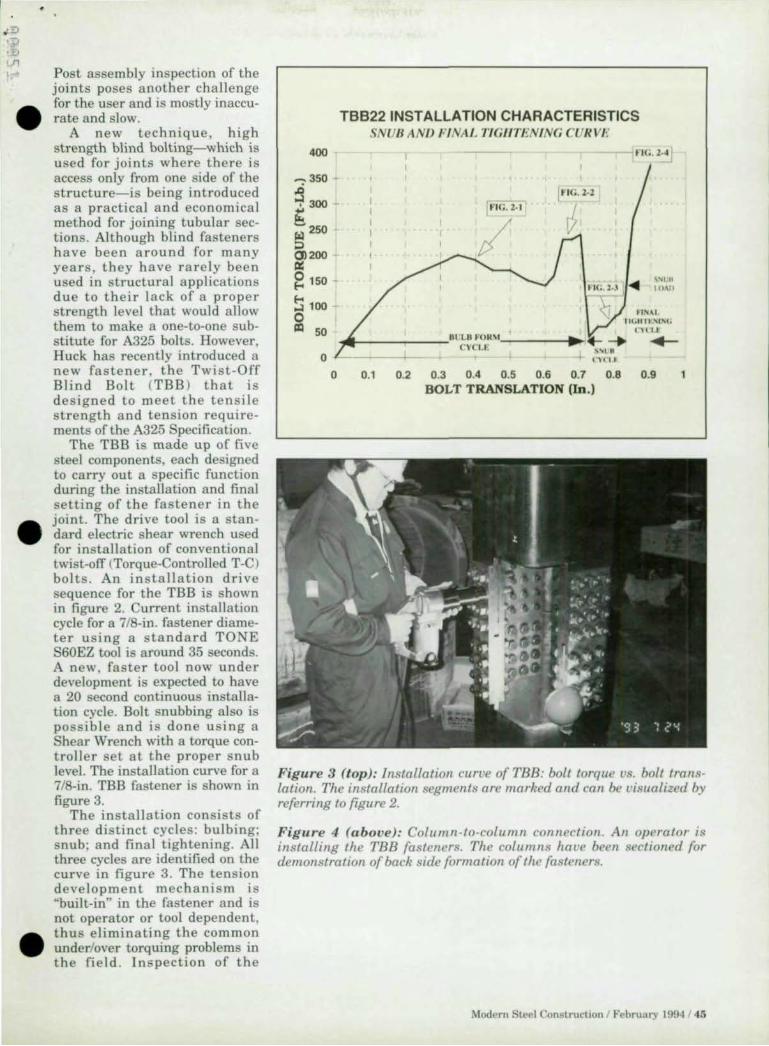
,;.!:>
:t 1/1
t
•
•
•
Post assembly inspection of the joints poses another challenge for the user and is mostly inaccurate and slow.
A new technique, high strength blind bolting-which is used for joints where there is access only from one side of the structure-is being introduced as a practical and economical method for joining tubular sections. Although blind fasteners have been around for many years, they have rarely been used in structural applications due to their lack of a proper strength level that would allow them to make a one-to-one substitute for A325 bolts. However, Huck has recently introduced a new fastener, the Twist-Off Blind Bolt (TBB ) that is designed to meet the tensile strength and tension requirements of the A325 Specification.
The TBB is made up of five steel components, each designed to carry out a specific function during the installation and final setting of the fastener in the joint. The drive tool is a standard electric shear wrench used for installation of conventional twist-off <Torque-Controlled T-C> bolts . An installation drive sequence for the TBB is shown in figure 2. Current installation cycle for a 7/8-in. fastener diameter using a standard TONE S60EZ tool is around 35 seconds. A new, faster tool now under development is expected to have a 20 second continuous installation cycle. Bolt snubbing also is possible and is done using a Shear Wrench with a torque controller set at the proper snub level. The installation curve for a 7/8-in. TBB fastener is shown in figure 3.
The installation consists of three distinct cycles: bulbing; snub; and final tightening. All three cycles are identified on the curve in figure 3. The tension development mechanism is "built-in" in the fastener and is not operator or tool dependent, t hu s eliminating the common underlover torquing problems in the field. Inspection of the
400
~35O
~ 300 -t -250 101 ::> 0)200 III: g 150 -
!:l100
~
TBB22 INSTALLATION CHARACTERISTICS SNUB ANIJ FINAl. TIGIITENING CUR VI!
1t lc:. 2.2
J " I( •. l . j .... ~ ~.~~I ,
~ UN"I 11(.11 11 ""',
CH I t 50 "'~ __ -r-__ 61 L6 FO." ____ _. . .... I- +-
cvcu. 0 1----1-- +
o ~1 ~ ~3 U ~ U ~ U U BOLT TRANSLATION (In.)
Figure 3 (top ): Instailation curve of TBB: boll torque vs. bolt lrans· lation. The instailation segments are marked and can be visualized by referring to figure 2.
Figure 4 (above): Column-to-column connection. An operator is installing the TBB fa steners. The columns have been sectioned for demonstration of back side formation of lhe fa steners.
Modern Steel Construction / Februa ry 199..1 / 45

, , , .' " :<
o ~ : , It ::
" " "
" " ~ :: " " 'ct :: " , " " " " , , ,
OOOOO~ V
:::= ==:"""".:,:- =.;: 000001 - - - - - 1
Figure 5 (above): H beam to tubular column connection.
Figure 6 (right): Column-tocolumn connection using TBB fastellers.
, , :1 " "
::) ': ::~ " " "
:i ~ " "
:: ~ " ~m ... " ,-m 9OI.TS
" " " " " , , ,
_,/'J Wlsr -OFF 8llWD BOLTS
~ (}-.- - ----~OOOOO -,,,··,,,,.,,1 ~OOOf~~
46 1 Modern Steel Construction I February 1994
installed fasteners is easy and is don e by measuring the protru-sion of the bolt after the installa- • tion. Too high or too low protrusions will nag the operator of an installation probl em. Also, unlike the conventional fasten-ing systems, outside exposure of the TBB prior to installation has no efTect on the bolt's prevailing friction factor si nce the thread system is "protected" within the assembly. Figure 4 shows an actual installation. Note that a section of the tubular column has been cut out for demonstra-tion of fastener function and blind side formation . In this particular joint , co nve ntion a l twi st-ofT bolts were used for the bottom half of the connection and TBB fasteners were used for the top ha lf.
Applications
In general, tw ist-off blind bolts could be used in all applications were access to one s ide of the st ructure is difficult or re s tricted. Examples of column-to-beam and . column-to-column connections using TBB fasteners are shown in figures 5 and 6. Productivity improvements in the order of two to three times are expected from u s ing the TBB system. Th e improvements are especially noticeable for the beam-to-tubu-lar column connections, where besides the elimination of weld-ing, diaphragm s and cumbe rsome assembly procedures associated with them will no longer be needed.
The joining process simplification ofTered by the TBB system allows users to either partially assemble the connections in the shop and fini sh it on the job site, or do the complete assembly on the job site, thus giving more latitude in terms of transportation options and material handling.
Huck expects the TBB fas teners to be in full production by the end of the first quarter of 1994.
Shahriar Sadri is director of • product development with Huck International, Inc.

•
•
•
CON ECTION
High Shear Nail
H i'ti has recently introduced the High Shear Nail IHSN ) for the
attachment of metal roof and Ooor deck to bar joist and light strllctural steel beams. Designed to be equivalent in allowable shear capacity to a 5/8-in. puddle weld, the nail is compatible with Hilti 's DX 36M Powder Actuated Fastening System .
ontact: Kenneth Walsh, Manager of Marketing Communications, Hilti Inc., 5400 South 122nd East Avenue, Tulsa, OK 74146 (800) 727-3427 ext. 6726.
Lock Pin & Collar
H uck International has intro duced a high-strength alterna
live to ordinary nuts and bolts: The Huck Lock Pin and Collar fastening system. It exceeds ASTM A325 and A490 requirements and meets AASHTO, ICBO, AlSC, and ASME requirements. The system is U.S. made, and the fastene rs a re completely traceable and factory mill certified. Contact: Mark Brenner, Huck Fastening Systems, 6 Thomas, Irvine, CA 92718 (714) 855-9000.
Direct Tension lndicators
Direct tension indicators CDT!) produced by J&M Turner are
now identified with a new trademark symbol as well as a lot identification number for complete product traceability. In addition, a fu ll range of metric DTIs are now available that meet the provisions of ASTM A325M and A490M . Contact: J&M Turner, 1310 Industrial Blvd. , Southamton , PA 18966 (800) 525-7193; fax (215) 953-1125.
Type I And Type m Bolts
S t. Loui s Screw & Bolt operates the only facility in North
America offering a full ra nge of Heavy Head High Strength Bolts, including A325 Structural Bolts from 1/2-in. through 1-112-in . diameter in all lengths. Everything is produced from steel melted and made in the U.S. to fu lfill both Type J a nd Type III (weathering stee\) requirements and feature an "'S L" trademark on its heads. For more information, contact: St. Louis Screw & Bolt, 6900 N. Broadway, St. Loui s, MO 63147 (800) 237-7059; fax (314) 389-7510.
Roll Threading
Fabsco Corp. has expanded its roll threading capacity to 3-in. diam-
PRODU C TS
eter so there's no need to upset large diameter rods to achieve full size thread e ngageme nt. Time a nd money can be saved by roll threading s ag rods and tie rods. Also stocked a re 5/8- in. , 3/4-in. and I -in . diameter roll thread anchor bolts as well as a large range of pla stic anc h or bolts s leeves up to 3-in. diameter. The company also carries hot dip galvanized bridge bearing studs up to 1-1I4-in . diameter. All steel inventory is mill certifiable and made in the U.S. Certification is provided upon request. Also, Fabsco features cold forming capacity up t.o 3/8-in. diameter in lengths up to 3-in. For more information, contact: Fabsco Corp., 1745 West 124th St., Calumet Park, IL 60643 (708) 371-7500; Fax (708) 371-7524.
Anchor Bolts & Tie Rods
H aydon Bolts manufacturers anchor bolls and lie rods up to
4·in. in diamete r. The products a re ofTered in ASTM A36, A449, A325, and A588. A complete line of standard a nd s pec ia l sizes of ASTM A325 and A490 are avai lab le in hexago n head s as we ll as button head shear bolts. For more informa· tion, contact: Haydon Bolts, Inc. , Adams Avenu e & Unily St reet, Philadelphia, PA 19124 -3196 (215 ) 537-8700; Fax (2 15) 537-5569.
Twist-Off Bolt
N ucor Fastener has deve loped a twist·ofT bolt wit h a major dif·
ference from competitive products: a hex head. This head makes the bolt easy to install, easy to remove, and easy to check its installation with a torque wrench. They a re fully tested and certified, including full compli . ance with FHWA, DOT and AASHTO specifications for bridge con· struction . For more info rmation , contact: Nucor Fastener, P .O. Box 6100, St. Joe, IN 46785 (800 ) 955-6826; (219) 337 -5394.
Tension Control
Rapid Tension Bolts from NSS Industries are a type of structur·
al bolt-nut·washer assembly where the proper tension is indicated when the spline has been sepa rated from the bolt. Installation is ach ieved by first assembling the bolt, washer & nut into the connection hole a nd tightening by hand until snug. Next, the 12-point socket of the install ation tool is engaged. Rapid tension is achieved by si mply pressing the trig-
STRUCTURAL CONSTRUCTION FASTENERS From foundation to roof Haydon is your one source. Quality bolts to ASTM standards at competitive prices. Direct from the manufacturer.
You name the structural anchor, bolt, nut or rod you need in the size, metal and finish you want. Either we have it in our large inventory, or we can make it for you in a hurry. We've been known for quality and fast service since 1864. And, we'll quote prices and give details right over the phone. Try us. Call :
(215) 537-8700 lax (215) 537-5569
HAYDON BOLTS, Inc .
Adams Ave. & Unity St. Philadelphia, PA 19124
1i ., ... .
~.,: ' ........ . r . ' ''' 1. /J, a .. "'.r . .... . o ' .... r'r ... r . •
Modern Steel Construction 1 February 1994 / 47

BODS HG
WEUNE SMART BOIlS KNOW "PROPER TENSION!" A-325 or A-490 high strength bolts.
Factory mill certification-traceable to each keg. Black or mechanically galvanized.
Full domestic
"THE LOWEST COST SYSTEM FOR PROPERLY INSTALLED HIGH STRENGTH BOLTS!"
48 / Modern Steel Construction / February 1994
PRODU CT S
ger of the installation tool; while the outer socket rotates clockwise, the . inner socket rotates counterclock· wise, ensuring a snug fit. Contact: NSS Industries, 9075 General Dr., Plymouth, MI 48170 (800) 221-5126.
Te ns ion Control Indicator
The TS Fastening System is a high-strength tension control
indicating system and is designed for the installation of high-strength A325 and A490 bolts. Contact: Bristol Machine Company, 19844 Quiroz Court, Walnut, CA 91789 (800) 798-9321.
Rapid Delivery
Specializing in meeting the needs of structural steel fabricators,
Mid-South Bolt & Screw Co. provides a wide range of products inc luding anchor bolts, tie rods, studs, crane rail bolts. U-bolts, J. bolts, swedge bolts, eye bolts, struc-tural hex bolts, tension control bolts, load indicator washers, concrete anchors, weld studs, threaded studs, plastic sleeves, c1evises, turnbuckles and all types of nuts, screws, bolts and washers . Three locations ofTer next-or second-day delivery to twothirds of the U.S . Contact: Mid . South Bolt & Screw Co., Inc., 499 Cave Road , Nashville , TN 37210 (800) 251-3520.
Prope r Tension Installa tion
The LeJeune Tension Cont rol Bolting System provides a cali
brated bolt, nut and washer assembly that installs at the proper tension for that particular size and grade of bolt. A-325 Type I and III , as well as A-490, Grades are available in 3/4-in. , 7/8- in. and 1-lI8-in. diameters. Contact: LeJeune Bolt Co., 8330 West 220th St., Lakeville, MN 55044 (800) 872-2658.
Thread ed Fast eners
Portland Bolt is a domestic man ufacturer of headed and threaded
fastening hardware up to 5-1/2- in . diameter and 40 ft. in length . The material is produced and certified to the latest ASTM and AlSC specifications. The company specializes in carbon , alloy, non-ferrous fasteners and hot-dipped galvanized coatings. For more information contact: Portland Bolt & Manufacturi ng Co., Inc., P.O . Box 2866, Portland, OR • 97208 (800) 547-6758.

l ur Tna-Tensinn holt \\',1'0 de ... lgnl\..1 \'(Ih,\( if you h.wl' to \'l'f1fy {he pnll~r lI1 ... tall,uion of
With one vcry IInpurtant .1J\',lIuage .1 hutton heaJ holt! Agall1, It .... almo ... t Imrxl ...... lhle "'lnn' you
m'cr other [\\1'-1(-0(( holt ... : a hex can't even get a wrench on the heaJ w test or remo\'c It.
head ... 'rl.'ml'\lnC thl' bolt or checking thc installation With But Y(lU can \,erify in ... talLII i(ln (If (1m hcx head h,llt \\ Ith the
n torque wrench IS Just ~h easy as in)wlli ng It. turn of ,1 \\'n ... t and ;1 cil llhriited torque wrench. (~ , . \ USing a qUiet, hand-held JXlwcr rool, our TnI.Ten"'lon Clearlh th1'" I .. one holt th.1I won't k,t y'\.lU
'y ... tem always pf(.l\'lue ... the correct ten"lon. It abo dlm1l1i-1tt:, ... crew up. Our Tru-Tcn ... ion ... y ... rem I, ~ll'o(l (ully traceahle ((I
npcmrnr ern,)f Junng as:-.cmhly, the holt ... come prc-a ... ...cmhletl our JOl1le ... t1c ... ouree ... , like ,!II Nucor I,t ... tener .... They're fully
,lI1J Y(IU can e\'l~n ... ,we money thank ... to the qUICk. ca ... y tc,reJ i-lIlJ certified, mciuJl11g compl!alll:c with FlIWA.
m .. t<ll1atH,lfl .1OJ hl\\'er co ... ts (or \,isuallnspC'clIon. nOT anJ AASHTO "'pcclhGltlon ... for hnJge n)fl ... truction.
But. m ... tall any hutton heaJ fcl'-ltcner compared to So. forget ahour cutting holh ()(f \vHh <l ron,:h if
our hex head fa .. tcner, ilnJ there .... no turnmg b.1ck. RCCilU"'C .. ll111ethlllg gne ... wnmg. Callu .... ll HOO/955-ohl6. FAX 219/
,t" almo't ,mp,,,,,hle l<l remm'o a hutton he,lll fa,tener, I'"U ))7·5394 or IInte PO Box 6100, St. J,,,,, I 467t15 10 tmJ
• milY c\'en neeJ a welder to burn It off. That co ... ts you tllnt:' out Illore a\xllit our Tru-Tcn ... ion ",\, ... rern. And get it la ... tener
and money. If you'd lIl ... t.llled nur hex head bolt In [he hr ... t
place you could rellHwe It With <l "'ll11ple, fom dollar wrench. I:iEBIi lJilfj\j\ =I 11 =I h {

------------------- - --- ---- ._---
A ISC Certification Categories I, n, TIl
Do you want to become certilied but arc just buried with work?
loITer assistance with the necessary paperwork plus trnining for your people.
McGowan Technical Services, Inc. 412-378-3916 fax: 412·378-3916
Images-3D 20-30 StnicturallFinite Element Analy~i '!'
Ea.'>y to learn and u.,e Autome<;h Generation Shear & Moment Diagram., Slatic. MOOal. Dynamic AISC Code Check Enforced Di ~placcmenl'" Large Problcm~ to 3.000 Joinl <; P·d Analy~i 'i
Complele Sialic Package - Only $795 Cele\ tial Soflware. 2150 Shallud A\e .. Sui te 12.00,
Berkeley. CA 94704 Tel: 510-843-0977 1 Fax : 510-848-9849
Fifty·nodc full function evaluation package for only S~9.95
Accurate Design A design/drafting ... en icc bu~ine!o;s !o;crvicing
cngineers. cOr1lractors and fabricators. Structural steel delai ling by the "iheet or lump ... um
Accur",e De,ign 8 11 Ayrault Road
Fairport. . Y .. 14450 716/425-2634
"Call now for a reasonable price quote."
HEWLETT-PA C KARD Computers/Peripherals
A cmnplctc line of u"ed and rcfurbiiohcd III} Equipment 10 fill all your computer need ... . L1')er printer'> . "canne" . dl "' !.. dri,e ... ploHe", (Draftpro. Drafuna<., lcr & Dc ... ignjcl). PC's and 9000 scrie~ worhtation.-, arc available for immediate dc1hery . Call our toll free number for additional information and pricing.
Ted Dasher & Associates 4117 2nd A venue South Birmingl101m, At 35222
800-638-~833 fax (205) 59 1· 1 108
GTSTRUDL New K Version wi th In teractive Graphics
and Links 10 CA D systems
Sialic. Non-Linear & Dynamic Analyses and Inlegrated Steel Design
Curved "eel Girder Bridge Module
For information contacl: Alex Krimotat at SC SolUlions (415) 903-5050
Classitied Ads
Reach 35.000 engineers. fabric<l tor,!o,. :.trchitccl'i. cont ractors. bridge officials and building 0" ners PLUS 3.000 structural engineering ~tudcnl s inexpcn .. ivel) with a clas~ified adveni ",cment in
Modern Steel Construction. I t'~ fast and easy- we even do lhe typesetting for you at no charge.
For rate and placement information. call: John B)' rne at (708) 699-6030.
50 I Modern Steel Construction I February 1994
ROLLING Beam-Angle-Tube-Pipe-Channel-Plate
Easy/Hard way Heavy Capacit ies Up to 36" w.F. Beam
209-466-9707 N.J . McCutchen. Inc.
123 W. Sonora St.. Stockton. CA 95203
Instant Steel Publication Information
•
Info on 'Ieel publication .. and .!.oftwarc i~ only a FREE phonc cnll awny. Call 800·(H4·2400 rrom any pushbullon phone and by rol · lowing the simple instnlctioll'" you call request inronnalion on : AISC Manuals & Supplcment ... : Specifications & Codes: DC!o.ign Guidc~ ; Technical & Fabricator Public<ltioll!<!o: Conference Proceedings: and AISC Software. Aflcr clliering the rcque ... tcd material on the phone's keypad. along with your fax machinc~ te lephone number. the materia l wi ll be immediatcly faxed to you .
CALL 800-644-2400
ADVERTISER 'S INDEX
American Welding Society ........................................................... .43
Bay Studies Disk ..................................................................... CIII Nicholas J . Bouras ....................................................................... Cll
Cadvantngc ................................................................................ 14 Chaparral Steel ............................................................................. 11 Comeq ............................................................................ _ ............... 30 Compu ter Detailing ...................................................................... 39 Computers & Structures Inc ....................................................... CJV Conxprl ........................................................................................ 36 Design Data ................................................................................. 7
EJE Industries ........................................ . ............................. 15
Haydon Bolts ............................................................................ .47
J&~1 Turner ............................................................................... 8
LeJeune Bolt ............................................................................ .48
l\{DX Software ................................................................. . ........ 16 /l.1id-Soulh Bolt ............................................................................... 16 McDonough Bolya rd Peck ............... ................ ............ .. ..... 33 Met roson .................................................................................... 25
National Steel Construct ion Conference ...................................... 17 Nucor Fas tener ................................................................................. 49
Omnitech ............................................................................................ 8 Optima Le ........................................................................................... 39
Pneutek, Inc ...................................................................................... 8 Portland Bolt ................................................................................ 33
Research Engineers ...................................................................... 5 RI SA Technologies .................................................................... 2 1
St . Louis Screw & Bol t ................................................................. 13 Steel J oist. Inst itute .................................................................... 20 Structural Engineers ...................................................................... 30 Structu ra l Sof\.ware ...................................................................... 37
TradeARBED ............................................................................... 3
Vulcra ft- ............................................................................... 26-27
\Vhitefnb ................................................................................... 21
,
•
•
•

Pr.ll.lnary ~.t ..... 0..190 o.t. • ••••••••••••.• !'I'T OIl • J' ... ~: lAJ1); IOCA, u.. I' pa .. .............. .
"-t. I)' Oi',) • CI"~4 PM .............. .
•• l J:~ .. ) 20 .. _ lAJ1)
iU ~ (1
" '" ,OJ
'" OJ
X·ClIlIt.r X, hrpoondcn>l.r
... "" ..... .u- n .. 00 JO 00 10 DO
SO .. .. " , .. ... ,to .. , . " 11 00
" .. .. to U 00 UI DO n 00
tArt! hctontd t.oe."-
• " . " 12.00
" .. 24 00 U 00
"""I " n. Dotfl 00 U " " Tt. OlIn 00 U 100 ,., Tt. o.!l 00 U U ." .. -00 u n n Tt._
\2 10 17 to U ItO ".1tO
Cot OlIn linl ~ .. , Cot .. c:o.t lSi .... D1. S1. n. at 1 Std C.1Ib To.
U " .. .. " ,
" " " .. " ,
" " " I .. " ,
U " .. .. " ,
" " .. " • , " " .. I .. " " " " " " ." " " .. " " .U

-
Computers • .... I ... IDe. 1995 UruverSlty Avenue Berkeley , Call1ornio 94704
TEL: 510/ 845·2177 FAX: 510/ 845-4096
Developed by Asluaf Hab1bullah & EclwClId L Wilson
•
General