Embed Size (px)
Citation preview

SAFE HANDLING AND ERECTION OF STEEL
JOISTS AND JOIST GIRDERS
WALTER WORTHLEY CARL PUGH, Jr. PERRY S. GREEN
Authors: Perry S. Green
Dr. Green is the Technical Director of the Steel Joist Institute which is headquartered in Myrtle Beach, SC. He has an undergraduate degree in Civil Engineering from Columbia University and a Masters Degree and PhD in Civil Engineering from Lehigh University. He serves on the SJI’s Composite, Education, Engineering Practice and Research Committees. He also serves on the Executive Committee of the Structural Stability Research Council; is a Main Committee Member of AISI’s Cold-Formed Steel Committee on Specifications; an Associate Member of ASCE and member of their Flexural and Compression Members and Fatigue and Fracture Committees. Carl Pugh, Jr.
Mr. Pugh is the Engineering Manager for New Millennium Building Systems in Salem, VA. He has been in the joist industry since 1985 and is a member of the SJI’s Composite Joist, Education and Engineering Practice Committees. He has a Bachelor of Science Degree in Civil Engineering from Virginia Polytechnic Institute and State University and is a registered Professional Engineer in ten states. Walter Worthley
Mr. Worthley is the Chief Engineer for Valley Joist in Fernley, NV. Previously, he worked for over 15 years in the design and construction of nuclear power plants. He has worked in his own consulting engineering firm doing design of light commercial buildings, forensic engineering and structural damage assessment. He is a member of the SJI’s Engineering Practice Committee and Seismic Subcommittee. He has a Bachelor of Science Degree in Civil Engineering from the University of Massachusetts at Lowell and is a registered Professional Engineer in several western and eastern states. Abstract:
The Steel Joist Institute has recently revised Technical Digest No. 9, “Handling and Erection of Steel Joists and Joist Girders” as a direct result of the changes that have been adopted in the workplace based on the new Occupational Safety and Health Administration safety standards issued in 2001. The technical digest, on which this paper is primarily based, concerns itself with the proper handling and erection procedures to be employed in the field to make certain that SJI joist products are not damaged, that they perform as specified, and above all, to ensure the safety of the erectors.
SAFE HANDLING AND ERECTION OF STEEL JOISTS AND JOIST GIRDERS
Perry S. Green, PhD, Carl Pugh, Jr., PE, and Walter Worthley, PE
INTRODUCTION
The first known application of steel joist construction was in the Bank of the State of New York building that was erected in 1855 at Williams St. and Exchange Place in New York City. The architect, James Renwick, developed a type of floor joist that was comprised of two 1/16 in. riveted wrought iron web plates with 4 x 1/8 in. top and bottom plates riveted to the web to form the joist. The building was razed in 1903. During the period 1885 to 1920 various proprietary and patented joist designs were manufactured including the O’Shea Joist in Chicago, St. Louis Joist, Berger Joist, Truscon Steel Joist, and the National Strip Steel Joist. All these joists had solid sheet steel for their webs and it was not until 1923 that the first “open web” steel joist appeared. The Massillon Bar Joist consisted of five bars: Two top chord bars, two bottom chord bars and a web bar. The web bar was bent to proper dimensions and the assembly arc welded at panel points into a Warren truss configuration. The design of each end of the joist gave it flexibility of span.
In June 1928, the Steel Joist Institute was formed by a group of joist manufacturers, Concrete Steel Co., New
York, NY, Gabriel Steel Co., Detroit, MI, Kalman Steel Corporation, Bethlehem, PA, The Macomber Steel Co., Canton, OH, and Truscon Steel Co., Youngstown, OH. The original purposes for which the Institute was founded were to standardize the methods of design and details of construction, to promote proper building regulations and to disseminate information relative to the proper use of steel joists. In December of that same year the Steel Joist Institute adopted the Standard Specification of Steel Joists, and in August 1929 the first standard loading table applicable to the design of joists by all member companies was approved. This loading table was later adopted as Simplified Practice Recommendation R 94-30 of the United States Department of Commerce. In April 1931 the first Code of Standard Practice was adopted.
The SJI’s first Catalog, Steel Joist Construction - A Handbook for Architects and Engineers on the Uses
and Properties of Steel Joists, was published January 1932. The catalog contained information on Open Web Steel Joists, Standard Specifications and Code of Standard Practice of the Steel Joist Institute, Handling and Erecting Steel Joists, Standard Steel Joist Loading Tables and Properties of Steel Joists. That catalog, in addition to the over 40 other catalogs that have been published subsequently by the SJI, contains information related to the proper handling and erection of steel joists. In 1932 the SJI provided recommendations on unloading, hauling, piling (storing), setting joists, decking, construction loads, centering, reinforcing for the top slab, wood sleepers, placing of concrete, and mechanical trades. The current Standard Specifications for Open Web Steel Joists, K-Series; Standard Specifications for Longspan and Deep Longspan Steel Joists, LH- and DLH-Series has a section on Erection Stability and Handling while the Standard Specifications for Joist Girders has a section on Handling and Erection. These specifications are contained in the 42nd Edition Catalog published by the Steel Joist Institute (SJI 2005).
Today, steel joists and Joist Girders are widely used products primarily in commercial, industrial and
institutional buildings. However, until this technical digest was first published in 1987, no definitive handbook on their handling and erection had been written. Since the original publication date, there have been numerous changes and innovations in the use of steel joists. Among these changes have been the introduction of new or expanded joist products, innovations in building materials and systems, changes in design philosophy, and the adoption of new building codes and federal regulations. Therefore, for these reasons the Steel Joist Institute determined that an extensive revision to Technical Digest No. 9 was required.
If a joist manufacturer is asked, “How good are your products?” the answer almost certainly would be: “only
as good as their installation.” A joist manufacturer can design and build joist products with remarkable intrinsic strength, but whether or not these products can deliver this strength is largely dependent on how well they are handled from the time they leave the manufacturing facility until they are permanently installed in the building.
The purpose of this paper is to present a clear and concise summary of what constitutes a safe installation of open web steel joists and Joist Girders. Though it is not possible to include every conceivable joist application or field condition that could be encountered in this paper, the reader should come away with a general understanding of the SJI recommended safe practices for handling, storing and erecting these products.
One of the most important aspects of safe erection of joist products is proper bridging. Bridging is a
component of the steel joist system that braces the joists against unanticipated horizontal movement during erection as well as during the placing of construction loads. A lateral displacement of the joist may mean that the construction load caused the joist to distort, roll over, or shift from its intended position resulting in both the ironworkers and joists falling. Much attention will be given to this critical component. Additionally, as a result of changes in code provisions and design requirements, bridging may be an integral part of the initial as well as final structural system and therefore should not be modified by field personnel without permission from the Engineer of Record and the joist manufacturer.
This paper will not attempt to address all hazards that may be present in a particular construction
environment. Pre-job planning and development of a site-specific erection plan that identifies hazards are very important. The implementation of systems and procedures to eliminate those hazards completes this process. It should be noted that the technical digest contains a discussion of several different types of systems used to protect employees, but regardless of the type selected it should be designed by a qualified person and employees should be trained in the proper use of the system.
OSHA HISTORY
Since 1984, representatives of the steel community have worked with the Department of Labor and the Occupational Safety and Health Administration (OSHA) to establish new rules for the safe erection of structural steel and as part of that rule, safe erection standards for Open Web Steel Joists. Table 1 highlights the significant events leading up to the current OSHA Safety Standards for Steel Erection. As stated in the Federal Register,
“By this notice the Occupational Safety and Health Administration (OSHA) revises the construction industry safety standards which regulate steel erection. The final rule enhances protections provided to workers engaged in steel erection and updates the general provisions that address steel erection. The final rule sets performance-oriented criteria, where possible, to protect employees from steel erection related hazards such as working under loads; hoisting, landing and placing decking; column stability; double connections; hoisting, landing and placing steel joists; and falls to lower levels.”
PRODUCTS Standard SJI Products - Shortspans
Open Web Steel Joists, K-Series, were primarily developed to provide structural support for floors and roofs of buildings. They possess the following advantages and features which have resulted in their wide use and acceptance throughout the United States and other countries. First and foremost, they are economical. For many types of buildings, no other products or methods for supporting floors and roofs can compete with steel joists. The advantages listed in the following paragraphs all contribute to the overall economy of using Open Web Steel Joists. K-Series are light in weight; they possess an exceptionally high strength-to-weight ratio in comparison with other building materials. Coupled with their low price per pound, they contribute significantly to lower building costs. An additional economy stemming from their light weight is the fact that the structural materials supporting the joists, such as beams and Joist Girders, columns, and the foundations themselves, can therefore be lighter, thus leading to even greater savings. Open Web Steel Joists represent unitized construction. Upon arrival at the job site, the joists are ready immediately for proper installation. No forming, pouring, curing, or stripping is required. Furthermore, their light weight makes the erection procedure simple and fast.
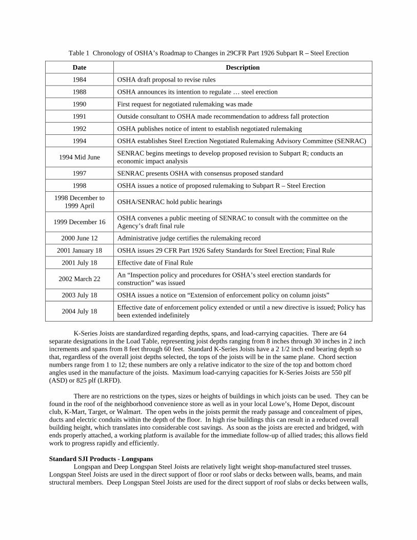
Table 1 Chronology of OSHA’s Roadmap to Changes in 29CFR Part 1926 Subpart R – Steel Erection
Date Description
1984 OSHA draft proposal to revise rules
1988 OSHA announces its intention to regulate … steel erection
1990 First request for negotiated rulemaking was made
1991 Outside consultant to OSHA made recommendation to address fall protection
1992 OSHA publishes notice of intent to establish negotiated rulemaking
1994 OSHA establishes Steel Erection Negotiated Rulemaking Advisory Committee (SENRAC)
1994 Mid June SENRAC begins meetings to develop proposed revision to Subpart R; conducts an economic impact analysis
1997 SENRAC presents OSHA with consensus proposed standard
1998 OSHA issues a notice of proposed rulemaking to Subpart R – Steel Erection
1998 December to 1999 April OSHA/SENRAC hold public hearings
1999 December 16 OSHA convenes a public meeting of SENRAC to consult with the committee on the Agency’s draft final rule
2000 June 12 Administrative judge certifies the rulemaking record
2001 January 18 OSHA issues 29 CFR Part 1926 Safety Standards for Steel Erection; Final Rule
2001 July 18 Effective date of Final Rule
2002 March 22 An “Inspection policy and procedures for OSHA’s steel erection standards for construction” was issued
2003 July 18 OSHA issues a notice on “Extension of enforcement policy on column joists”
2004 July 18 Effective date of enforcement policy extended or until a new directive is issued; Policy has been extended indefinitely
K-Series Joists are standardized regarding depths, spans, and load-carrying capacities. There are 64
separate designations in the Load Table, representing joist depths ranging from 8 inches through 30 inches in 2 inch increments and spans from 8 feet through 60 feet. Standard K-Series Joists have a 2 1/2 inch end bearing depth so that, regardless of the overall joist depths selected, the tops of the joists will be in the same plane. Chord section numbers range from 1 to 12; these numbers are only a relative indicator to the size of the top and bottom chord angles used in the manufacture of the joists. Maximum load-carrying capacities for K-Series Joists are 550 plf (ASD) or 825 plf (LRFD).
There are no restrictions on the types, sizes or heights of buildings in which joists can be used. They can be found in the roof of the neighborhood convenience store as well as in your local Lowe’s, Home Depot, discount club, K-Mart, Target, or Walmart. The open webs in the joists permit the ready passage and concealment of pipes, ducts and electric conduits within the depth of the floor. In high rise buildings this can result in a reduced overall building height, which translates into considerable cost savings. As soon as the joists are erected and bridged, with ends properly attached, a working platform is available for the immediate follow-up of allied trades; this allows field work to progress rapidly and efficiently. Standard SJI Products - Longspans
Longspan and Deep Longspan Steel Joists are relatively light weight shop-manufactured steel trusses. Longspan Steel Joists are used in the direct support of floor or roof slabs or decks between walls, beams, and main structural members. Deep Longspan Steel Joists are used for the direct support of roof slabs or decks between walls,
beams, and main structural members. The LH- and DLH-Series have been designed for the purpose of extending the use of joists to spans and loads in excess of those covered by Open Web Steel Joists, K-Series.
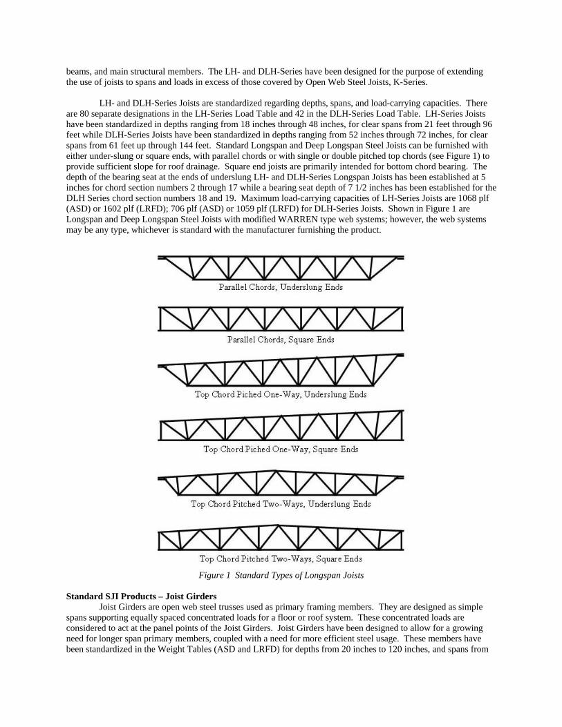
LH- and DLH-Series Joists are standardized regarding depths, spans, and load-carrying capacities. There are 80 separate designations in the LH-Series Load Table and 42 in the DLH-Series Load Table. LH-Series Joists have been standardized in depths ranging from 18 inches through 48 inches, for clear spans from 21 feet through 96 feet while DLH-Series Joists have been standardized in depths ranging from 52 inches through 72 inches, for clear spans from 61 feet up through 144 feet. Standard Longspan and Deep Longspan Steel Joists can be furnished with either under-slung or square ends, with parallel chords or with single or double pitched top chords (see Figure 1) to provide sufficient slope for roof drainage. Square end joists are primarily intended for bottom chord bearing. The depth of the bearing seat at the ends of underslung LH- and DLH-Series Longspan Joists has been established at 5 inches for chord section numbers 2 through 17 while a bearing seat depth of 7 1/2 inches has been established for the DLH Series chord section numbers 18 and 19. Maximum load-carrying capacities of LH-Series Joists are 1068 plf (ASD) or 1602 plf (LRFD); 706 plf (ASD) or 1059 plf (LRFD) for DLH-Series Joists. Shown in Figure 1 are Longspan and Deep Longspan Steel Joists with modified WARREN type web systems; however, the web systems may be any type, whichever is standard with the manufacturer furnishing the product.
Figure 1 Standard Types of Longspan Joists
Standard SJI Products – Joist Girders
Joist Girders are open web steel trusses used as primary framing members. They are designed as simple spans supporting equally spaced concentrated loads for a floor or roof system. These concentrated loads are considered to act at the panel points of the Joist Girders. Joist Girders have been designed to allow for a growing need for longer span primary members, coupled with a need for more efficient steel usage. These members have been standardized in the Weight Tables (ASD and LRFD) for depths from 20 inches to 120 inches, and spans from
20 feet to 120 feet. Joist Girders are furnished with underslung ends and lower chord extensions. The standard depth at the bearing ends has been established at 7 1/2 inches for all Joist Girders. The Weight Tables list the approximate weight in pounds per linear foot for a Joist Girder supporting the concentrated panel point loads shown. Non-Standard SJI Products
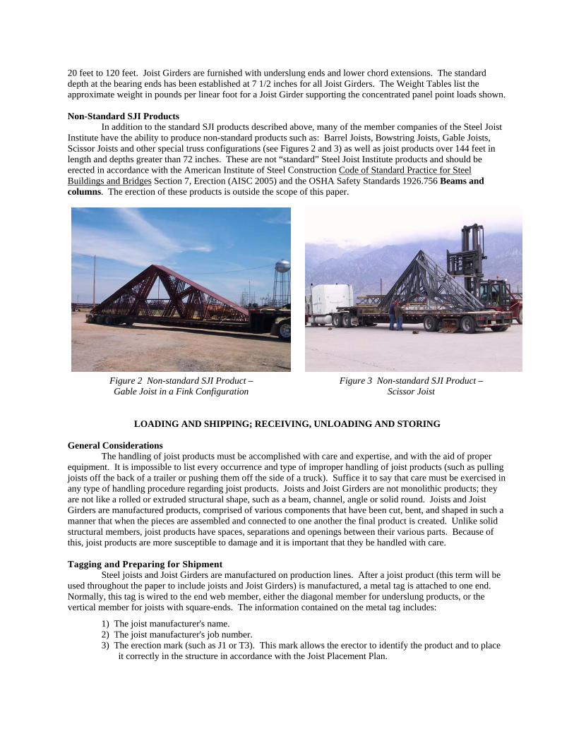
In addition to the standard SJI products described above, many of the member companies of the Steel Joist Institute have the ability to produce non-standard products such as: Barrel Joists, Bowstring Joists, Gable Joists, Scissor Joists and other special truss configurations (see Figures 2 and 3) as well as joist products over 144 feet in length and depths greater than 72 inches. These are not “standard” Steel Joist Institute products and should be erected in accordance with the American Institute of Steel Construction Code of Standard Practice for Steel Buildings and Bridges Section 7, Erection (AISC 2005) and the OSHA Safety Standards 1926.756 Beams and columns. The erection of these products is outside the scope of this paper.
Figure 2 Non-standard SJI Product – Gable Joist in a Fink Configuration
Figure 3 Non-standard SJI Product – Scissor Joist
LOADING AND SHIPPING; RECEIVING, UNLOADING AND STORING General Considerations
The handling of joist products must be accomplished with care and expertise, and with the aid of proper equipment. It is impossible to list every occurrence and type of improper handling of joist products (such as pulling joists off the back of a trailer or pushing them off the side of a truck). Suffice it to say that care must be exercised in any type of handling procedure regarding joist products. Joists and Joist Girders are not monolithic products; they are not like a rolled or extruded structural shape, such as a beam, channel, angle or solid round. Joists and Joist Girders are manufactured products, comprised of various components that have been cut, bent, and shaped in such a manner that when the pieces are assembled and connected to one another the final product is created. Unlike solid structural members, joist products have spaces, separations and openings between their various parts. Because of this, joist products are more susceptible to damage and it is important that they be handled with care. Tagging and Preparing for Shipment
Steel joists and Joist Girders are manufactured on production lines. After a joist product (this term will be used throughout the paper to include joists and Joist Girders) is manufactured, a metal tag is attached to one end. Normally, this tag is wired to the end web member, either the diagonal member for underslung products, or the vertical member for joists with square-ends. The information contained on the metal tag includes:
1) The joist manufacturer's name. 2) The joist manufacturer's job number. 3) The erection mark (such as J1 or T3). This mark allows the erector to identify the product and to place
it correctly in the structure in accordance with the Joist Placement Plan.
The handling of joist products begins in the joist plant immediately after the joists have been manufactured. Depending on size and length, several joists or Joist Girders are bundled together with metal strapping and a paper or plastic tag listing the mark numbers contained in the bundle is usually attached to the bundle. They are painted, when required, and moved to a covered location where they are allowed to air dry. The standard shop paint is intended to protect the steel for only a short period of exposure in ordinary atmospheric conditions and shall be considered an impermanent and provisional coating.
When a delivery date has been set, the joist products are typically loaded onto flat bed trailers. The joist bundles are chained or strapped down to the trailer once the trailer has been loaded. Joist products are usually shipped upside down. This provides greater stability to the bundles since the top chord is a heavier member than the bottom chord; and, in the more common underslung condition, the top chord extends the entire length of the joist or Joist Girder, while the bottom chord is shorter in length. Also, the lowest possible center of gravity is achieved when the joist products are loaded in this manner. There are occasions when the joists may be shipped in a “top chord up” fashion or bundled “one up/ one down”. These cases are rare but may be necessary due to job site or shipping considerations. Loading and Shipping
Since the vast majority of joists are shipped by truck, attention will be concentrated on this means of delivery. Most shipments are made by trucks pulling flat bed trailers. However, some shipments, particularly LTL (less than truck load) loads, are loaded onto closed-sided trailers. Flat Bed Trailer - Shipment of joist products on flat bed trailers is by far the most common form of conveyance. A few of the obvious reasons are:
• Loading and unloading is much simpler than by any other means of shipment. • Far greater flexibility of loading is possible in regards to the bulk, length, weight and height of the
shipment. • Delivery is made directly to the job site. • Timing of job site arrival can be estimated with reasonable accuracy.
During the loading operation, the joist bundles are placed on the bed of the trailer, usually filling out the
complete width of the bed. Spacers (normally wooden slats called dunnage) are usually placed on top of each layer of joists, perpendicular to their length. Additional bundles are then placed on top of the spacers until the load is complete. When the loading operation is complete, the entire load is chained (or strapped) down to prevent the load from falling off the side of the trailer or prevent the load from shifting or overturning during transit. Closed Trailer - The loading of joists onto closed trailers can be difficult, since the loading crane cannot simply lower the joists in place. Instead, the crane must balance the joist bundles on the end of the trailer bed, then "slide" them to the interior, hopefully without gouging the trailer bed too badly or damaging the joists. With a small number of short, light joists, this does not present a major problem. However, the loading of a full shipment of joists in a closed trailer is strongly discouraged. Open Top Trailer - Also known as "Rag Tops", these trailers also lend themselves to the loading of joists for LTL shipments since the lifting crane can simply lower the joist bundles into place once the tarpaulin top has been rolled back. For shipping fuller loads, difficulties regarding the positioning of bundles, the removing of lifting cables or slings, and the danger to the personnel inside the trailer body, are all present. Receiving
The following three procedures should be considered mandatory regardless of the method of conveyance of the joist products from the joist manufacturer to the job site:
1) Inspection of the load for indicators of possible instability such as shifted product or broken banding. 2) Inspection of the joist products for evidence of physical damage. 3) Verification of items being delivered by comparison with the piece count and description on the
Delivery Ticket or Bill of Lading.
When a truck arrives, the load should be inspected before releasing the chains or straps that are securing the load. Bundles may have shifted in transit and could be in danger of falling off the truck or the banding straps may be broken causing the bundle to separate or “de-nest”. Such de-nesting can produce a dangerous situation. If these or other signs of instability are present, steps must be taken to assure that joist products will not fall when the chains or straps are released. Once the stability of the load is confirmed, the chains or straps may be released and the unloading process can proceed.
A general inspection for any damage to the joist products is quite simple at the time of receipt and it is critical that someone check the shipment for damage. The receiving party should look for any permanent bend or deformation in the chords, web members or end bearing seats. Broken welds, displaced or bent web members, or any other deficiency or damage should be noted on the receiving documents and reported to job site supervision. The manufacturer will not be responsible for damage to the product unless a notation is made on the delivery documents. The manufacturer should be notified immediately if damaged material is detected. A piece count also should be made of all joists, Joist Girders and accessories at the time of receipt. Such count should be checked against the delivery documents to ensure that all items have been included in the shipment. A piece count is neither difficult nor time-consuming and is invaluable in preventing job delays later on in the event that some material is missing. As in the case of damage, unless notation is made on the delivery documents, the manufacturer will not be responsible for claims of missing material. Diligence in this process will assure that all of the joist products and accessories listed on the delivery documents have arrived at the job site in good condition. Unloading Joist Products
Joist products are typically unloaded by either crane or forklift. Unless physically or mechanically impossible, joist products should be unloaded by bundles. Care must be exercised to ensure that the removal of any given bundle does not cause another bundle to fall. The entire top layer of joist products should be unloaded first, beginning with the outer bundles. Subsequent layers should be unloaded the same way. Bundles should be lifted off the truck and placed down gently. They should never be dropped. If, in the process of receiving or unloading, it is determined that any of the joist products arrived in a damaged condition, a notation should be clearly entered on the delivery documents and the manufacturer should be notified immediately so that the damage can be repaired or the product replaced as quickly as possible. Bundles should never be lifted by their banding. The banding material is not designed to carry the bundle’s weight. A banding strap may hold initially, but it can break without warning, seriously injuring workers, damaging equipment or the joist products. Sorting hooks should never be used for unloading or erecting joist products. Unloading with a Crane
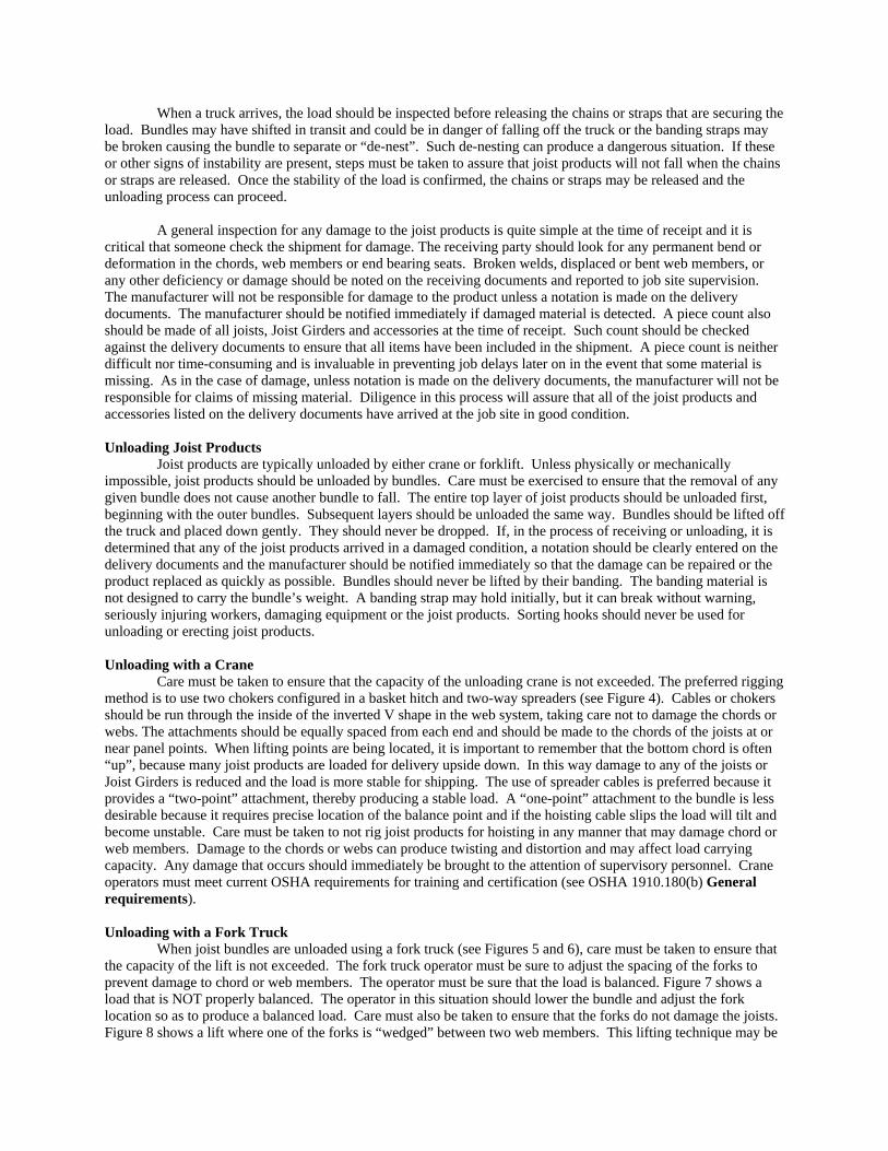
Care must be taken to ensure that the capacity of the unloading crane is not exceeded. The preferred rigging method is to use two chokers configured in a basket hitch and two-way spreaders (see Figure 4). Cables or chokers should be run through the inside of the inverted V shape in the web system, taking care not to damage the chords or webs. The attachments should be equally spaced from each end and should be made to the chords of the joists at or near panel points. When lifting points are being located, it is important to remember that the bottom chord is often “up”, because many joist products are loaded for delivery upside down. In this way damage to any of the joists or Joist Girders is reduced and the load is more stable for shipping. The use of spreader cables is preferred because it provides a “two-point” attachment, thereby producing a stable load. A “one-point” attachment to the bundle is less desirable because it requires precise location of the balance point and if the hoisting cable slips the load will tilt and become unstable. Care must be taken to not rig joist products for hoisting in any manner that may damage chord or web members. Damage to the chords or webs can produce twisting and distortion and may affect load carrying capacity. Any damage that occurs should immediately be brought to the attention of supervisory personnel. Crane operators must meet current OSHA requirements for training and certification (see OSHA 1910.180(b) General requirements). Unloading with a Fork Truck
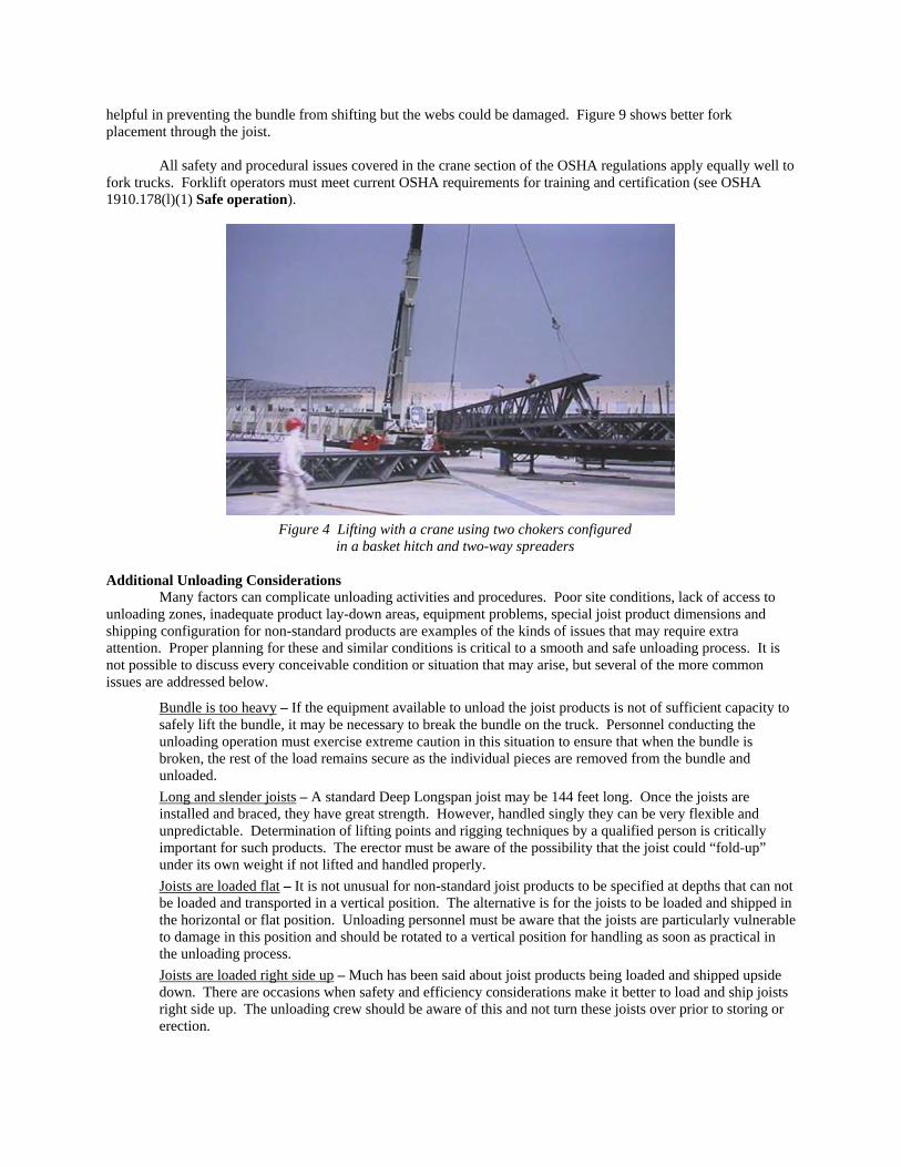
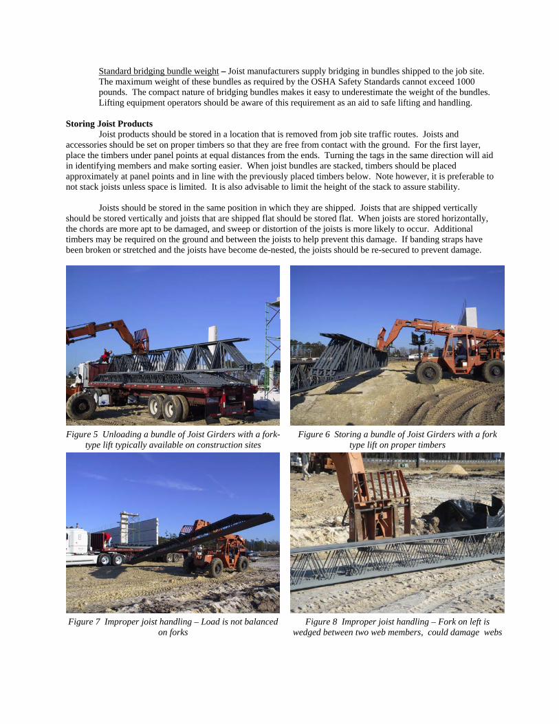
When joist bundles are unloaded using a fork truck (see Figures 5 and 6), care must be taken to ensure that the capacity of the lift is not exceeded. The fork truck operator must be sure to adjust the spacing of the forks to prevent damage to chord or web members. The operator must be sure that the load is balanced. Figure 7 shows a load that is NOT properly balanced. The operator in this situation should lower the bundle and adjust the fork location so as to produce a balanced load. Care must also be taken to ensure that the forks do not damage the joists. Figure 8 shows a lift where one of the forks is “wedged” between two web members. This lifting technique may be
helpful in preventing the bundle from shifting but the webs could be damaged. Figure 9 shows better fork placement through the joist.
All safety and procedural issues covered in the crane section of the OSHA regulations apply equally well to fork trucks. Forklift operators must meet current OSHA requirements for training and certification (see OSHA 1910.178(l)(1) Safe operation).
Figure 4 Lifting with a crane using two chokers configured
in a basket hitch and two-way spreaders Additional Unloading Considerations
Many factors can complicate unloading activities and procedures. Poor site conditions, lack of access to unloading zones, inadequate product lay-down areas, equipment problems, special joist product dimensions and shipping configuration for non-standard products are examples of the kinds of issues that may require extra attention. Proper planning for these and similar conditions is critical to a smooth and safe unloading process. It is not possible to discuss every conceivable condition or situation that may arise, but several of the more common issues are addressed below.
Bundle is too heavy – If the equipment available to unload the joist products is not of sufficient capacity to safely lift the bundle, it may be necessary to break the bundle on the truck. Personnel conducting the unloading operation must exercise extreme caution in this situation to ensure that when the bundle is broken, the rest of the load remains secure as the individual pieces are removed from the bundle and unloaded. Long and slender joists – A standard Deep Longspan joist may be 144 feet long. Once the joists are installed and braced, they have great strength. However, handled singly they can be very flexible and unpredictable. Determination of lifting points and rigging techniques by a qualified person is critically important for such products. The erector must be aware of the possibility that the joist could “fold-up” under its own weight if not lifted and handled properly. Joists are loaded flat – It is not unusual for non-standard joist products to be specified at depths that can not be loaded and transported in a vertical position. The alternative is for the joists to be loaded and shipped in the horizontal or flat position. Unloading personnel must be aware that the joists are particularly vulnerable to damage in this position and should be rotated to a vertical position for handling as soon as practical in the unloading process. Joists are loaded right side up – Much has been said about joist products being loaded and shipped upside down. There are occasions when safety and efficiency considerations make it better to load and ship joists right side up. The unloading crew should be aware of this and not turn these joists over prior to storing or erection.
Standard bridging bundle weight – Joist manufacturers supply bridging in bundles shipped to the job site. The maximum weight of these bundles as required by the OSHA Safety Standards cannot exceed 1000 pounds. The compact nature of bridging bundles makes it easy to underestimate the weight of the bundles. Lifting equipment operators should be aware of this requirement as an aid to safe lifting and handling.
Storing Joist Products
Joist products should be stored in a location that is removed from job site traffic routes. Joists and accessories should be set on proper timbers so that they are free from contact with the ground. For the first layer, place the timbers under panel points at equal distances from the ends. Turning the tags in the same direction will aid in identifying members and make sorting easier. When joist bundles are stacked, timbers should be placed approximately at panel points and in line with the previously placed timbers below. Note however, it is preferable to not stack joists unless space is limited. It is also advisable to limit the height of the stack to assure stability.
Joists should be stored in the same position in which they are shipped. Joists that are shipped vertically should be stored vertically and joists that are shipped flat should be stored flat. When joists are stored horizontally, the chords are more apt to be damaged, and sweep or distortion of the joists is more likely to occur. Additional timbers may be required on the ground and between the joists to help prevent this damage. If banding straps have been broken or stretched and the joists have become de-nested, the joists should be re-secured to prevent damage.
Figure 5 Unloading a bundle of Joist Girders with a fork-
type lift typically available on construction sites Figure 6 Storing a bundle of Joist Girders with a fork
type lift on proper timbers
Figure 7 Improper joist handling – Load is not balanced
on forks Figure 8 Improper joist handling – Fork on left is
wedged between two web members, could damage webs
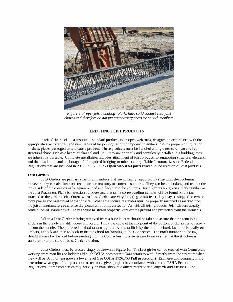
Figure 9 Proper joist handling - Forks have solid contact with joist
chords and therefore do not put unnecessary pressure on web members
ERECTING JOIST PRODUCTS
Each of the Steel Joist Institute’s standard products is an open web truss, designed in accordance with the appropriate specifications, and manufactured by joining various component members into the proper configuration; in short, pieces put together to create a product. These products must be handled with greater care than a rolled structural shape such as a beam or channel and, until they are correctly and completely installed in a building, they are inherently unstable. Complete installation includes attachment of joist products to supporting structural elements and the installation and anchorage of all required bridging or other bracing. Table 2 summarizes the Federal Regulations that are included in 29 CFR 1926.757 - Open web steel joists related to the erection of joist products. Joist Girders
Joist Girders are primary structural members that are normally supported by structural steel columns; however, they can also bear on steel plates on masonry or concrete supports. They can be underslung and rest on the top or side of the columns or be square-ended and frame into the columns. Joist Girders are given a mark number on the Joist Placement Plans for erection purposes and that same corresponding number will be found on the tag attached to the girder itself. Often, when Joist Girders are very long (e.g. >100 feet), they may be shipped in two or more pieces and assembled at the job site. When this occurs, the mates must be properly matched as marked from the joist manufacturer; otherwise the pieces will not fit correctly. As with all joist products, Joist Girders usually come bundled upside down. They should be stored properly, kept off the ground and protected from the elements.
When a Joist Girder is being removed from a bundle, care should be taken to assure that the remaining girders in the bundle are still secure and stable. Hook the cable at the midpoint of the bottom of the girder to remove it from the bundle. The preferred method to turn a girder over is to lift it by the bottom chord, lay it horizontally on timbers, unhook and then re-hook to the top chord for hoisting to the Connectors. The mark number on the tag should always be checked before sending it to the Connectors. It is necessary to make sure that the structure is stable prior to the start of Joist Girder erection.
Joist Girders must be erected singly as shown in Figure 10. The first girder can be erected with Connectors working from man lifts or ladders although OSHA does permit Connectors to work directly from the structure when they will be 30 ft. or less above a lower level (see OSHA 1926.760 Fall protection). Each erection company must determine what type of fall protection to use for a given project in accordance with current OSHA Federal Regulations. Some companies rely heavily on man lifts while others prefer to use lanyards and lifelines. One
should always make sure that the identification tag end on the Joist Girder is properly oriented before making the connection.
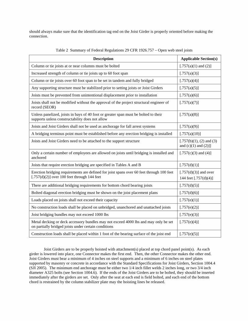
Table 2 Summary of Federal Regulations 29 CFR 1926.757 – Open web steel joists
Description Applicable Section(s)
Column or tie joists at or near columns must be bolted [.757(a)(1) and (2)]
Increased strength of column or tie joists up to 60 foot span [.757(a)(3)]
Column or tie joists over 60 foot span to be set in tandem and fully bridged [.757(a)(4)]
Any supporting structure must be stabilized prior to setting joists or Joist Girders [.757(a)(5)]
Joists must be prevented from unintentional displacement prior to installation [.757(a)(6)]
Joists shall not be modified without the approval of the project structural engineer of record (SEOR)
[.757(a)(7)]
Unless panelized, joists in bays of 40 foot or greater span must be bolted to their supports unless constructability does not allow
[.757(a)(8)]
Joists and Joist Girders shall not be used as anchorage for fall arrest systems [.757(a)(9)]
A bridging terminus point must be established before any erection bridging is installed [.757(a)(10)]
Joists and Joist Girders need to be attached to the support structure [.757(b)(1), (2) and (3) and (c)(1) and (2)]]
Only a certain number of employees are allowed on joists until bridging is installed and anchored
[.757(c)(3) and (4)]
Joists that require erection bridging are specified in Tables A and B [.757(d)(1)]
Erection bridging requirements are defined for joist spans over 60 feet through 100 feet [.757(d)(2)] over 100 feet through 144 feet
[.757(d)(3)] and over 144 feet [.757(d)(4)]
There are additional bridging requirements for bottom chord bearing joists [.757(d)(5)]
Bolted diagonal erection bridging must be shown on the joist placement plans [.757(d)(6)]
Loads placed on joists shall not exceed their capacity [.757(e)(1)]
No construction loads shall be placed on unbridged, unanchored and unattached joists [.757(e)(2)]
Joist bridging bundles may not exceed 1000 lbs [.757(e)(3)]
Metal decking or deck accessory bundles may not exceed 4000 lbs and may only be set on partially bridged joists under certain conditions
[.757(e)(4)]
Construction loads shall be placed within 1 foot of the bearing surface of the joist end [.757(e)(5)]
Joist Girders are to be properly hoisted with attachment(s) placed at top chord panel point(s). As each girder is lowered into place, one Connector makes the first end. Then, the other Connector makes the other end. Joist Girders must bear a minimum of 4 inches on steel supports and a minimum of 6 inches on steel plates supported by masonry or concrete in accordance with the Standard Specifications for Joist Girders, Section 1004.4 (SJI 2005). The minimum end anchorage must be either two 1/4 inch fillet welds 2 inches long, or two 3/4 inch diameter A325 bolts (see Section 1004.6). If the ends of the Joist Girders are to be bolted, they should be inserted immediately after the girders are set. Only after the seat at each end is field bolted, and each end of the bottom chord is restrained by the column stabilizer plate may the hoisting lines be released.
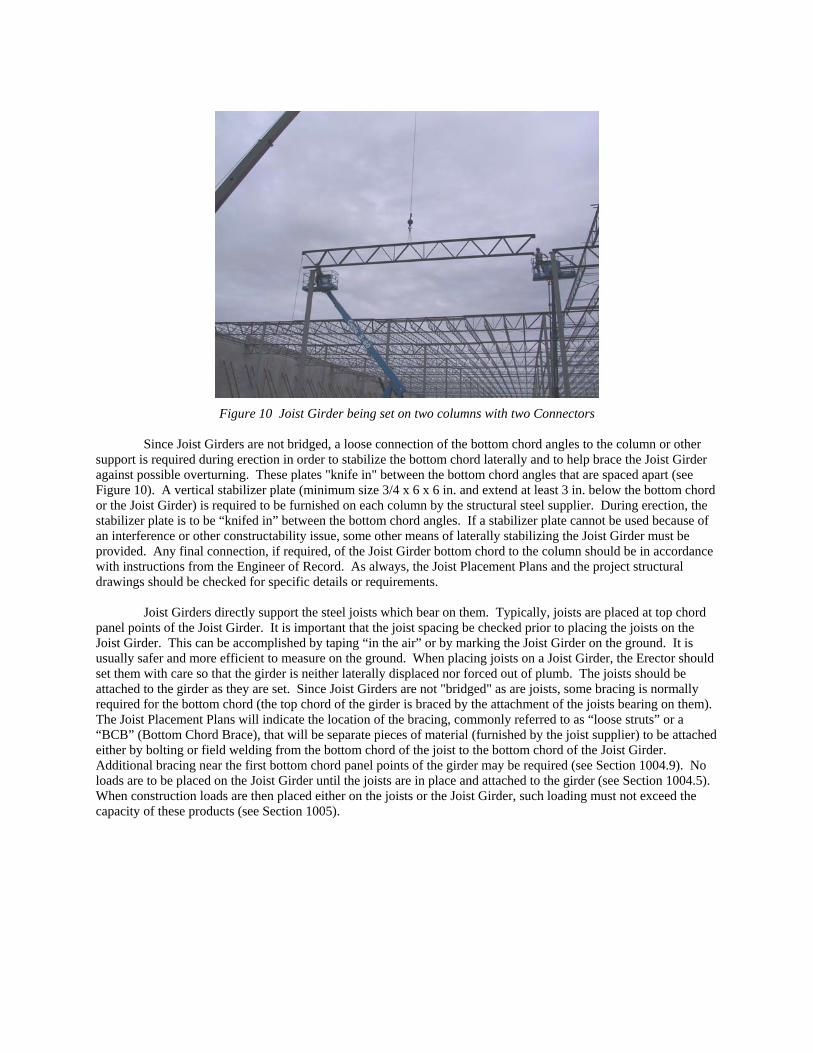
Figure 10 Joist Girder being set on two columns with two Connectors
Since Joist Girders are not bridged, a loose connection of the bottom chord angles to the column or other
support is required during erection in order to stabilize the bottom chord laterally and to help brace the Joist Girder against possible overturning. These plates "knife in" between the bottom chord angles that are spaced apart (see Figure 10). A vertical stabilizer plate (minimum size 3/4 x 6 x 6 in. and extend at least 3 in. below the bottom chord or the Joist Girder) is required to be furnished on each column by the structural steel supplier. During erection, the stabilizer plate is to be “knifed in” between the bottom chord angles. If a stabilizer plate cannot be used because of an interference or other constructability issue, some other means of laterally stabilizing the Joist Girder must be provided. Any final connection, if required, of the Joist Girder bottom chord to the column should be in accordance with instructions from the Engineer of Record. As always, the Joist Placement Plans and the project structural drawings should be checked for specific details or requirements.
Joist Girders directly support the steel joists which bear on them. Typically, joists are placed at top chord panel points of the Joist Girder. It is important that the joist spacing be checked prior to placing the joists on the Joist Girder. This can be accomplished by taping “in the air” or by marking the Joist Girder on the ground. It is usually safer and more efficient to measure on the ground. When placing joists on a Joist Girder, the Erector should set them with care so that the girder is neither laterally displaced nor forced out of plumb. The joists should be attached to the girder as they are set. Since Joist Girders are not "bridged" as are joists, some bracing is normally required for the bottom chord (the top chord of the girder is braced by the attachment of the joists bearing on them). The Joist Placement Plans will indicate the location of the bracing, commonly referred to as “loose struts” or a “BCB” (Bottom Chord Brace), that will be separate pieces of material (furnished by the joist supplier) to be attached either by bolting or field welding from the bottom chord of the joist to the bottom chord of the Joist Girder. Additional bracing near the first bottom chord panel points of the girder may be required (see Section 1004.9). No loads are to be placed on the Joist Girder until the joists are in place and attached to the girder (see Section 1004.5). When construction loads are then placed either on the joists or the Joist Girder, such loading must not exceed the capacity of these products (see Section 1005).
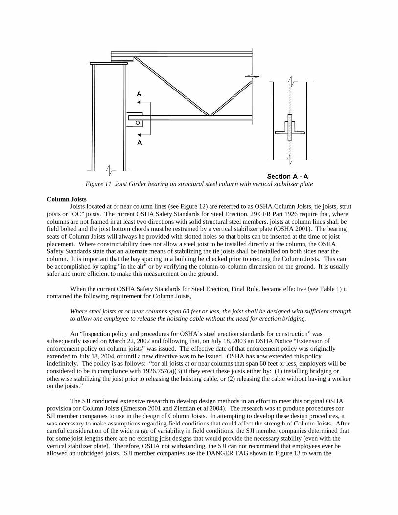
Figure 11 Joist Girder bearing on structural steel column with vertical stabilizer plate
Column Joists
Joists located at or near column lines (see Figure 12) are referred to as OSHA Column Joists, tie joists, strut joists or “OC” joists. The current OSHA Safety Standards for Steel Erection, 29 CFR Part 1926 require that, where columns are not framed in at least two directions with solid structural steel members, joists at column lines shall be field bolted and the joist bottom chords must be restrained by a vertical stabilizer plate (OSHA 2001). The bearing seats of Column Joists will always be provided with slotted holes so that bolts can be inserted at the time of joist placement. Where constructability does not allow a steel joist to be installed directly at the column, the OSHA Safety Standards state that an alternate means of stabilizing the tie joists shall be installed on both sides near the column. It is important that the bay spacing in a building be checked prior to erecting the Column Joists. This can be accomplished by taping "in the air" or by verifying the column-to-column dimension on the ground. It is usually safer and more efficient to make this measurement on the ground.
When the current OSHA Safety Standards for Steel Erection, Final Rule, became effective (see Table 1) it contained the following requirement for Column Joists,
Where steel joists at or near columns span 60 feet or less, the joist shall be designed with sufficient strength to allow one employee to release the hoisting cable without the need for erection bridging.
An “Inspection policy and procedures for OSHA’s steel erection standards for construction” was
subsequently issued on March 22, 2002 and following that, on July 18, 2003 an OSHA Notice “Extension of enforcement policy on column joists” was issued. The effective date of that enforcement policy was originally extended to July 18, 2004, or until a new directive was to be issued. OSHA has now extended this policy indefinitely. The policy is as follows: “for all joists at or near columns that span 60 feet or less, employers will be considered to be in compliance with 1926.757(a)(3) if they erect these joists either by: (1) installing bridging or otherwise stabilizing the joist prior to releasing the hoisting cable, or (2) releasing the cable without having a worker on the joists.”
The SJI conducted extensive research to develop design methods in an effort to meet this original OSHA provision for Column Joists (Emerson 2001 and Ziemian et al 2004). The research was to produce procedures for SJI member companies to use in the design of Column Joists. In attempting to develop these design procedures, it was necessary to make assumptions regarding field conditions that could affect the strength of Column Joists. After careful consideration of the wide range of variability in field conditions, the SJI member companies determined that for some joist lengths there are no existing joist designs that would provide the necessary stability (even with the vertical stabilizer plate). Therefore, OSHA not withstanding, the SJI can not recommend that employees ever be allowed on unbridged joists. SJI member companies use the DANGER TAG shown in Figure 13 to warn the
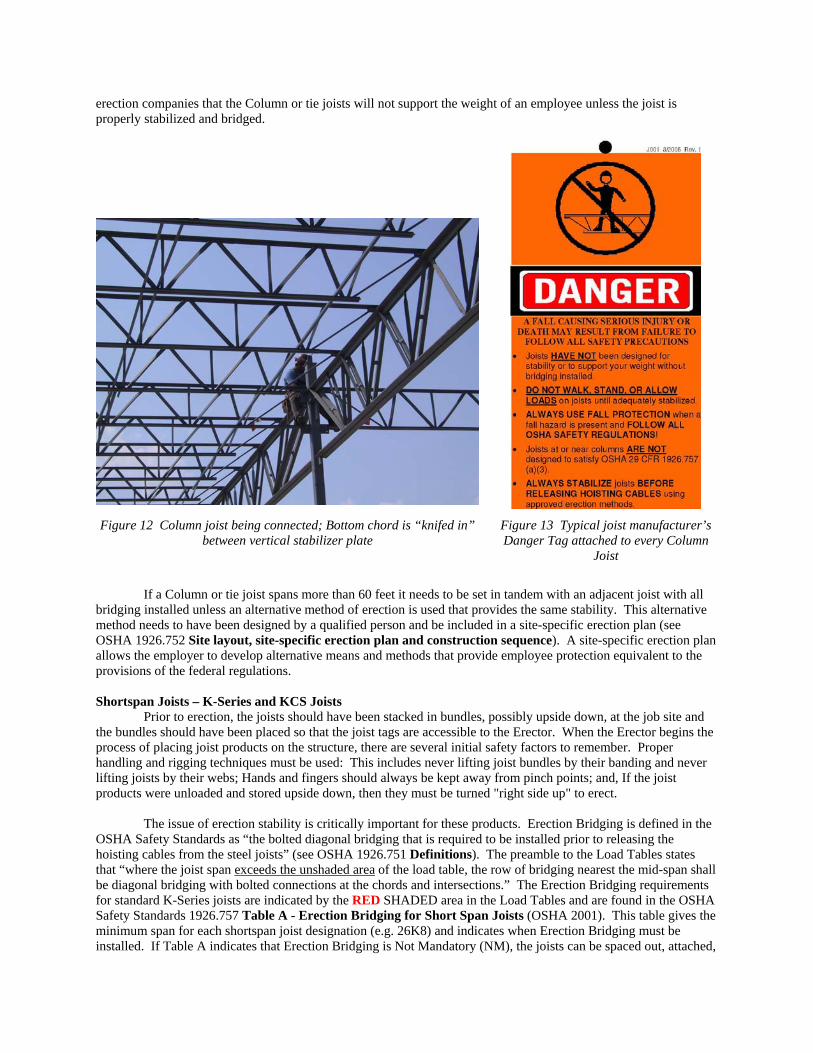
erection companies that the Column or tie joists will not support the weight of an employee unless the joist is properly stabilized and bridged.
Figure 12 Column joist being connected; Bottom chord is “knifed in”
between vertical stabilizer plate
Figure 13 Typical joist manufacturer’s Danger Tag attached to every Column
Joist
If a Column or tie joist spans more than 60 feet it needs to be set in tandem with an adjacent joist with all
bridging installed unless an alternative method of erection is used that provides the same stability. This alternative method needs to have been designed by a qualified person and be included in a site-specific erection plan (see OSHA 1926.752 Site layout, site-specific erection plan and construction sequence). A site-specific erection plan allows the employer to develop alternative means and methods that provide employee protection equivalent to the provisions of the federal regulations. Shortspan Joists – K-Series and KCS Joists
Prior to erection, the joists should have been stacked in bundles, possibly upside down, at the job site and the bundles should have been placed so that the joist tags are accessible to the Erector. When the Erector begins the process of placing joist products on the structure, there are several initial safety factors to remember. Proper handling and rigging techniques must be used: This includes never lifting joist bundles by their banding and never lifting joists by their webs; Hands and fingers should always be kept away from pinch points; and, If the joist products were unloaded and stored upside down, then they must be turned "right side up" to erect.
The issue of erection stability is critically important for these products. Erection Bridging is defined in the OSHA Safety Standards as “the bolted diagonal bridging that is required to be installed prior to releasing the hoisting cables from the steel joists” (see OSHA 1926.751 Definitions). The preamble to the Load Tables states that “where the joist span exceeds the unshaded area of the load table, the row of bridging nearest the mid-span shall be diagonal bridging with bolted connections at the chords and intersections.” The Erection Bridging requirements for standard K-Series joists are indicated by the RED SHADED area in the Load Tables and are found in the OSHA Safety Standards 1926.757 Table A - Erection Bridging for Short Span Joists (OSHA 2001). This table gives the minimum span for each shortspan joist designation (e.g. 26K8) and indicates when Erection Bridging must be installed. If Table A indicates that Erection Bridging is Not Mandatory (NM), the joists can be spaced out, attached,
and then bridged in accordance with the SJI Standard Specifications for Open Web Steel Joists, K-Series Section 6 (SJI 2005).
If Erection Bridging is required, each K-Series joist must be placed in accordance with the Joist Placement Plans and held with the hoisting equipment until both sides of the bearing seat on one end of the joist can be attached and the required bolted diagonal erection bridging is installed. The bridging row(s) must be anchored to prevent lateral movement of the joist (see Section 6). The required Erection Bridging must be installed as the row of bridging nearest the mid-span of the joist. The Erection Bridging must also be anchored to prevent lateral movement of the joist prior to the hoisting cables being released. The final attachment of the joist ends can then be made by either bolting or welding to the support structure as shown on the contract structural drawings.
In bays where Erection Bridging is not required, it may be permissible to land the joists in bundles. Before
this can be done, joists must be sorted out on the ground and proper numbers placed in bundles for erection. One must be careful when cutting the banding, keep hands and feet clear, as the joists may move and sometimes fall over when the banding is cut. Typically, four to six joists will be hoisted in a bundle, depending on the actual number required in the bay. Again, make sure all of the tags are turned in the proper direction; Check that the ends are even; and, All the joists are in proper sequence to be spread out on the building. Refer to the Joist Placement Plans for proper joist spacing and length of bearing. The spacing of joists in bays must be marked on the supporting beams or Joist Girders. This is typically done after members are erected, but with proper planning can be done on the ground. The final locations must be in accordance with the Joist Placement Plans.
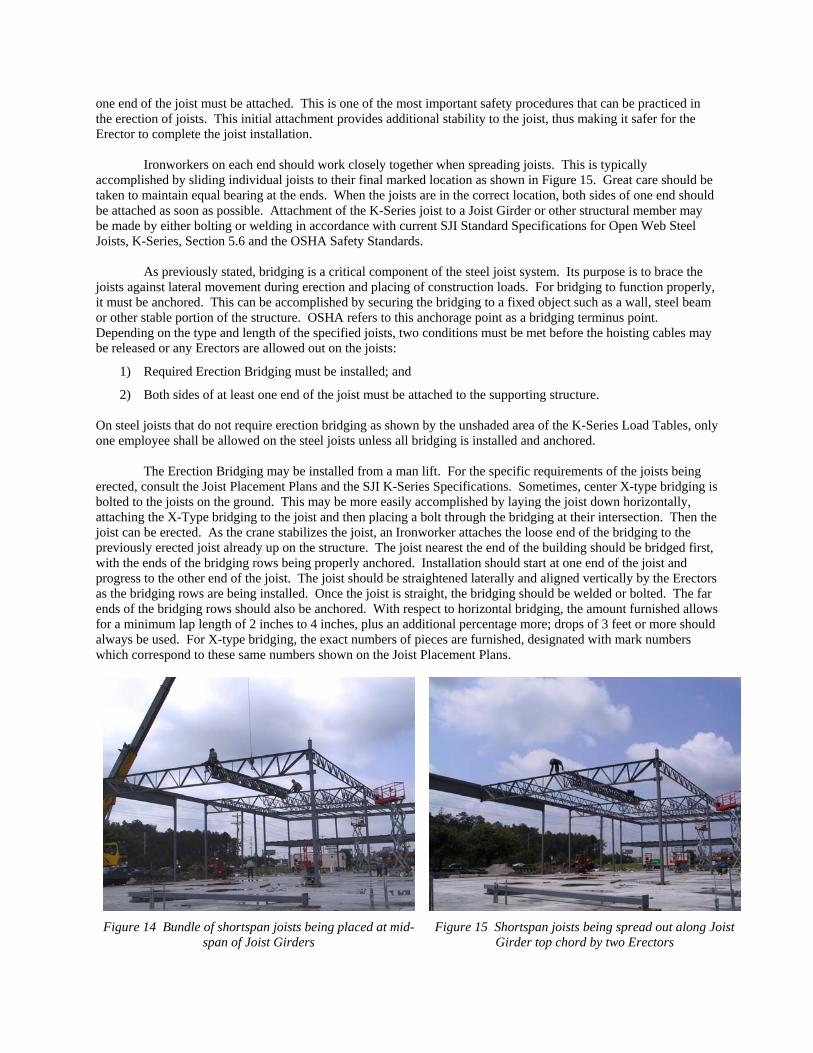
When erecting joists in bundles, Connectors should land the bundle on the supporting structure as close as possible to the center of the bay (see Figure 14). Check for proper bearing at each end before releasing the hoisting cables. When releasing the cables, be sure to hold them until they clear the bundle or the crane operator swings the boom away from the bundle so that they don't hang up. After the cables are released, make sure all the joist ends are sitting flat on their supports. If necessary, use a spud wrench to shift the joists into the flat position. If the joists are not to be spread and attached promptly, the bundle should be re-secured to prevent unintentional movement to keep them from falling.
In the case where all of the joists in a bundle are to be placed in the building next to one another, the bundle may be lifted and set in place on the building. A joist bundle should never be lifted by the banding. In order for this method to be utilized, the following four conditions must apply:
1) All of the joists in the bundle are turned the same way - that is, they are not bundled one up, one down, etc.
2) All of the joists are the same length.
3) None of the joists are staggered lengthwise in the bundle.
4) The joist tagged ends are oriented in the proper direction. If the joists are being erected in bundles, the banding can be broken after the bundle has been placed on the supporting structure, prior to release of the hoisting cables.
If the above four conditions do not apply, the joist bundles must first be turned right side up (if stored upside down), then broken open on the ground, with care being taken not to damage the joists as the banding is broken. The joists can then be lifted onto the building individually by attachment of hooks or cables to the top chord, at top chord panel points, and placed in accordance with the Joist Placement Plans. In certain situations it may be advantageous for joists to be re-bundled and hoisted as a group. Remember, each joist has a metal, embossed tag that carries the erection mark number, the contract number and the name of the joist manufacturer; the mark number on the joist tag needs to be matched with the mark number on the Joist Placement Plans for proper placement. In those instances where a joist is not symmetrical, the Joist Placement Plans will indicate where the "Tag End" of the joist is to be placed. The "Tag End" is that end of the joist to which the metal tag is attached.
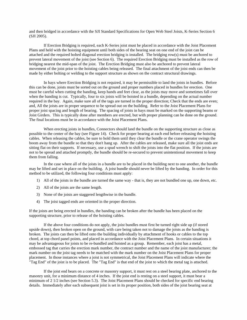
If the joist end bears on a concrete or masonry support, it must rest on a steel bearing plate, anchored to the masonry unit, for a minimum distance of 4 inches. If the joist end is resting on a steel support, it must bear a minimum of 2 1/2 inches (see Section 5.3). The Joist Placement Plans should be checked for specific end bearing details. Immediately after each subsequent joist is set in its proper position, both sides of the joist bearing seat at
one end of the joist must be attached. This is one of the most important safety procedures that can be practiced in the erection of joists. This initial attachment provides additional stability to the joist, thus making it safer for the Erector to complete the joist installation.
Ironworkers on each end should work closely together when spreading joists. This is typically accomplished by sliding individual joists to their final marked location as shown in Figure 15. Great care should be taken to maintain equal bearing at the ends. When the joists are in the correct location, both sides of one end should be attached as soon as possible. Attachment of the K-Series joist to a Joist Girder or other structural member may be made by either bolting or welding in accordance with current SJI Standard Specifications for Open Web Steel Joists, K-Series, Section 5.6 and the OSHA Safety Standards.
As previously stated, bridging is a critical component of the steel joist system. Its purpose is to brace the joists against lateral movement during erection and placing of construction loads. For bridging to function properly, it must be anchored. This can be accomplished by securing the bridging to a fixed object such as a wall, steel beam or other stable portion of the structure. OSHA refers to this anchorage point as a bridging terminus point. Depending on the type and length of the specified joists, two conditions must be met before the hoisting cables may be released or any Erectors are allowed out on the joists:
1) Required Erection Bridging must be installed; and
2) Both sides of at least one end of the joist must be attached to the supporting structure. On steel joists that do not require erection bridging as shown by the unshaded area of the K-Series Load Tables, only one employee shall be allowed on the steel joists unless all bridging is installed and anchored.
The Erection Bridging may be installed from a man lift. For the specific requirements of the joists being erected, consult the Joist Placement Plans and the SJI K-Series Specifications. Sometimes, center X-type bridging is bolted to the joists on the ground. This may be more easily accomplished by laying the joist down horizontally, attaching the X-Type bridging to the joist and then placing a bolt through the bridging at their intersection. Then the joist can be erected. As the crane stabilizes the joist, an Ironworker attaches the loose end of the bridging to the previously erected joist already up on the structure. The joist nearest the end of the building should be bridged first, with the ends of the bridging rows being properly anchored. Installation should start at one end of the joist and progress to the other end of the joist. The joist should be straightened laterally and aligned vertically by the Erectors as the bridging rows are being installed. Once the joist is straight, the bridging should be welded or bolted. The far ends of the bridging rows should also be anchored. With respect to horizontal bridging, the amount furnished allows for a minimum lap length of 2 inches to 4 inches, plus an additional percentage more; drops of 3 feet or more should always be used. For X-type bridging, the exact numbers of pieces are furnished, designated with mark numbers which correspond to these same numbers shown on the Joist Placement Plans.
Figure 14 Bundle of shortspan joists being placed at mid-
span of Joist Girders Figure 15 Shortspan joists being spread out along Joist
Girder top chord by two Erectors
In certain design applications, the joists are designed to bear on the bottom chord. This produces a “top heavy” condition. Therefore, they must be braced with an additional row of X-type bridging at or near the bearing support as they are being erected.
If joists don’t fit or there is an interference with other materials, do not cut or alter the joists. Written permission and instructions from the joist manufacturer and approval from the Engineer of Record must be obtained prior to making any necessary field modifications to the joist products. Longspan and Deep Longspan Joists – LH- and DLH-Series
As with K-Series and KCS Joists, Longspan, LH-Series and Deep Longspan, DLH-Series Joists are usually delivered upside down and banded in bundles. Each joist has a metal embossed tag which carries the contract number, the erection mark number, and the manufacturer’s name. Prior to erection, the joists should have been stored properly off the ground and protected from the elements.
Once again, the issue of Erection Bridging is very important. The Erection Bridging requirements for standard LH-Series joists are indicated by the RED or BLUE SHADED areas in the Load Tables and are also found in the OSHA Safety Standards 1926.757 Table B - Erection Bridging for Long Span Joists (OSHA 2001). This table gives the minimum span for each longspan joist designation (e.g. 32LH06) and indicates when Erection Bridging must be installed. Erection Bridging is the bolted diagonal bridging that is required to be installed prior to releasing the hoisting cables. If Table B indicates that Erection Bridging is Not Mandatory (NM), the joists can be spaced out, attached, and then bridged in accordance with the SJI Standard Specifications for Longspan Joists, LH-Series Section 105 (SJI 2005).
If Erection Bridging is required, each longspan joist must be set in its proper position in accordance with the Joist Placement Plans and held with the hoisting equipment until both sides of one end of the joist bearing seat is attached and the bolted diagonal Erection Bridging is installed. Where the span of the steel joist is less than 60 feet, the Erection Bridging must be installed as the row of bridging nearest the mid-span of the joist. Where the span of the steel joist is over 60 feet through 100 feet, the required Erection Bridging must be installed as the two rows of bridging nearest the third points of the joist. The bridging row(s) must be anchored to prevent lateral movement of the joist (see Section 105). The final attachment of the joist ends can then be made by either bolting or welding to the support structure as shown on the contract structural drawings.
The Erection Bridging requirements for standard DLH-Series joists are indicated by the BLUE or GREY SHADED areas in the Load Tables. Erection Bridging is required for all Deep Long Span Joists. Each DLH-Series joist must be set in its proper position and held with the hoisting equipment until both sides of one end of the joist is attached and the bolted diagonal Erection Bridging is installed. Where the span of the steel joist is over 60 feet through 100 feet, the required Erection Bridging as indicated by the BLUE shading must be installed as the two rows of bridging nearest the third points of the joist. Where the span of the steel joist is over 100 feet through 144 feet as indicated by the GRAY shading, all rows of bridging are considered Erection Bridging and must be completely installed. The hoisting cables are not to be released until the Erection Bridging is installed and anchored to prevent lateral movement of the joist. Both ends of the joist must then be permanently fastened down.
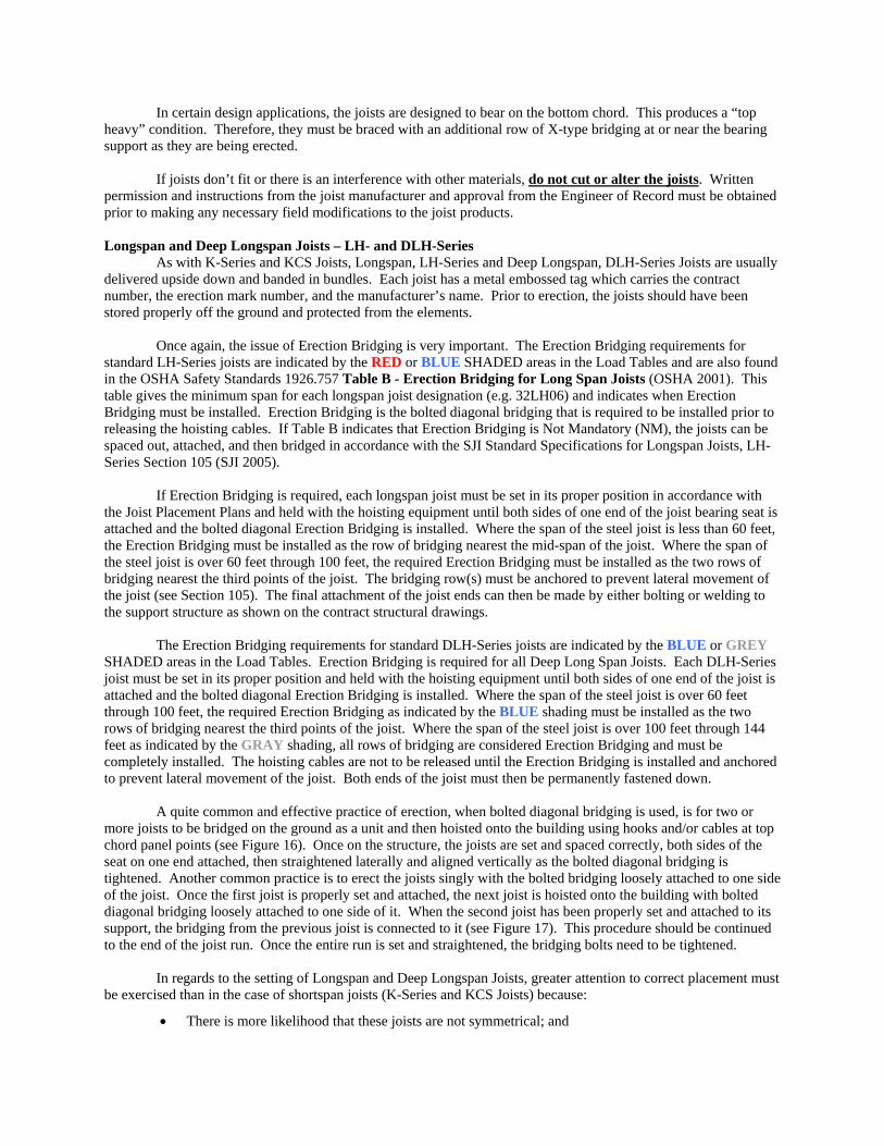
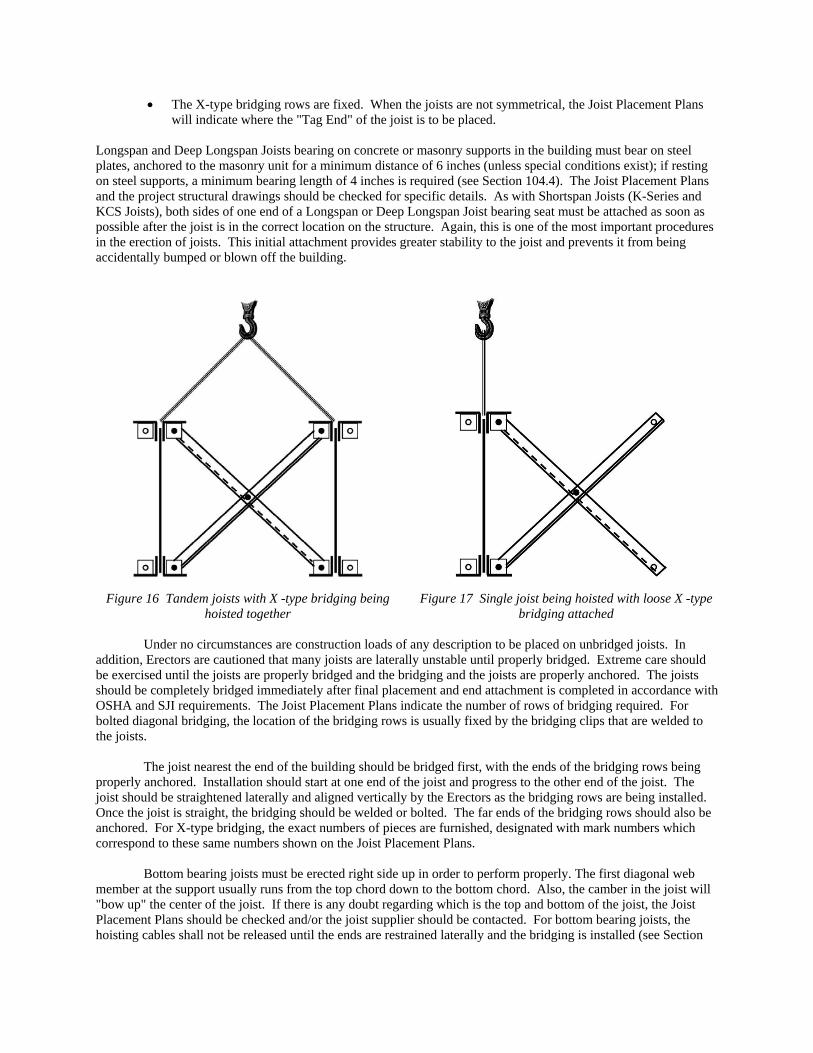
A quite common and effective practice of erection, when bolted diagonal bridging is used, is for two or more joists to be bridged on the ground as a unit and then hoisted onto the building using hooks and/or cables at top chord panel points (see Figure 16). Once on the structure, the joists are set and spaced correctly, both sides of the seat on one end attached, then straightened laterally and aligned vertically as the bolted diagonal bridging is tightened. Another common practice is to erect the joists singly with the bolted bridging loosely attached to one side of the joist. Once the first joist is properly set and attached, the next joist is hoisted onto the building with bolted diagonal bridging loosely attached to one side of it. When the second joist has been properly set and attached to its support, the bridging from the previous joist is connected to it (see Figure 17). This procedure should be continued to the end of the joist run. Once the entire run is set and straightened, the bridging bolts need to be tightened.
In regards to the setting of Longspan and Deep Longspan Joists, greater attention to correct placement must be exercised than in the case of shortspan joists (K-Series and KCS Joists) because:
• There is more likelihood that these joists are not symmetrical; and
• The X-type bridging rows are fixed. When the joists are not symmetrical, the Joist Placement Plans will indicate where the "Tag End" of the joist is to be placed.
Longspan and Deep Longspan Joists bearing on concrete or masonry supports in the building must bear on steel plates, anchored to the masonry unit for a minimum distance of 6 inches (unless special conditions exist); if resting on steel supports, a minimum bearing length of 4 inches is required (see Section 104.4). The Joist Placement Plans and the project structural drawings should be checked for specific details. As with Shortspan Joists (K-Series and KCS Joists), both sides of one end of a Longspan or Deep Longspan Joist bearing seat must be attached as soon as possible after the joist is in the correct location on the structure. Again, this is one of the most important procedures in the erection of joists. This initial attachment provides greater stability to the joist and prevents it from being accidentally bumped or blown off the building.
Figure 16 Tandem joists with X -type bridging being
hoisted together Figure 17 Single joist being hoisted with loose X -type
bridging attached
Under no circumstances are construction loads of any description to be placed on unbridged joists. In addition, Erectors are cautioned that many joists are laterally unstable until properly bridged. Extreme care should be exercised until the joists are properly bridged and the bridging and the joists are properly anchored. The joists should be completely bridged immediately after final placement and end attachment is completed in accordance with OSHA and SJI requirements. The Joist Placement Plans indicate the number of rows of bridging required. For bolted diagonal bridging, the location of the bridging rows is usually fixed by the bridging clips that are welded to the joists.
The joist nearest the end of the building should be bridged first, with the ends of the bridging rows being properly anchored. Installation should start at one end of the joist and progress to the other end of the joist. The joist should be straightened laterally and aligned vertically by the Erectors as the bridging rows are being installed. Once the joist is straight, the bridging should be welded or bolted. The far ends of the bridging rows should also be anchored. For X-type bridging, the exact numbers of pieces are furnished, designated with mark numbers which correspond to these same numbers shown on the Joist Placement Plans.
Bottom bearing joists must be erected right side up in order to perform properly. The first diagonal web member at the support usually runs from the top chord down to the bottom chord. Also, the camber in the joist will "bow up" the center of the joist. If there is any doubt regarding which is the top and bottom of the joist, the Joist Placement Plans should be checked and/or the joist supplier should be contacted. For bottom bearing joists, the hoisting cables shall not be released until the ends are restrained laterally and the bridging is installed (see Section
105). Normally, a row of diagonal bridging at the ends of the joists is specified in order to provide stability. Where a bottom bearing joist is extended beyond its support to form a cantilevered end, a row of diagonal bridging near the support should first be installed. In addition, the project structural drawings may indicate a row of diagonal bridging in the cantilevered portion to provide lateral stability. Care should be exercised in installing this bridging since the cantilever is supported at only one end. If the joists have bottom chords extended over and connected to a column, beam, wall, or other structure, the connection should be made in accordance with the project structural drawings and/or instructions from the Engineer of Record.
Longspan and Deep Longspan Joists, LH- and DLH-Series may have a single sloped or a double sloped top chord. In the case of a single sloped top chord, the Erector must be sure to set the joist "right-end-to" (the Joist Placement Plans will show where the "Tag End" is to be placed) and to place the bridging pieces in the correct location for easy erection. All field-welding of the joists and bridging must be done with considerable care. In general, the component members of the joists and, in particular the bridging pieces are relatively thin; careless or heavy-handed welding can easily damage these members. Erection Bridging
The SJI K-Series and LH- and DLH-Series Load Tables (SJI 2005) show the total safe uniformly distributed loads for standard products at various spans. As the span increases for a particular joist designation, the uniformly distributed load-carrying capacity decreases. The Load Tables also indicate when the span becomes too great for a particular joist designation to be erected without Erection Bridging. The quantity and location of the required Erection Bridging has been described in the preceeding sections for each joist series.
The mark numbers of the bolted bridging are shown on the Joist Placement Plans where they occur. Where the bundles of bridging are marked, but not the individual bridging pieces, it is incumbent upon the Erector to identify each bridging mark number after the bundles have been broken. This can be accomplished by comparing the lengths of the pieces to the appropriate bridging Bill of Material. In some instances, the joist manufacturer may place a tag on the diagonal bridging itself so that it can be placed more easily in the correct location on the structure.
Following the attachment of one end of the joist, the bridging is installed as indicated on the Joist Placement Plans. If Erection Bridging is required, it must be installed as the joists are erected and before the hoisting cables are released as previously described. It is the Erector's responsibility to ensure that the joists are straight lengthwise, and that they are vertically plumb. Any sweep in an erected joist should be removed and any vertical misalignment corrected as the bridging is installed. A row of bridging nearest one end of the joist is installed next after the installation of any required Erection Bridging. Bridging installation progresses from one row of bridging to the adjacent row until all rows have been installed and anchored properly. Each row of bridging must be properly anchored in order to provide the restraint required to stabilize the joists during erection.
Bolted bridging allows adjustment in joist alignment by means of slotted holes in the bridging itself. Bridging clips with slotted holes are welded to K-Series joists, in which case the bridging may be punched with either holes or slots. The joists must be straightened before the bolted connections are tightened. Both ends of each row of bridging must be anchored securely.
The vast majority of bridging is welded, horizontal type. This bridging is typically furnished as an angle shape in standard 20 foot lengths. A sufficient amount of bridging angle is shipped to the jobsite to provide two inch to four inch laps, plus a percentage more to allow for short drops; however, drops of three feet or more should be used. The horizontal bridging is welded to the top and bottom chords of the joists and the joists are aligned. Care must be exercised in welding the bridging because the materials being welded (both the bridging and the joist chords) may be quite thin; carelessness can result in the burning away of a portion of either the joist chord or the bridging. Therefore, field welding shall be performed in such a manner that no damage to the joists or bridging results. Heavy-handed or excessive welding can easily "blow-out" a portion of the joist chord or the bridging. The SJI Standard Specifications for Open Web Steel Joists, K-Series Section 5.4 (SJI 2005) requires that each welded bridging connection resist a horizontal force of not less than 700 pounds. The SJI Standard Specifications for Longspan Steel Joists, LH-Series and Deep Longspan Steel Joists, DLH-Series requires that each bridging connection to the joist must be able to resist the horizontal bracing force shown in Section 104.5, Table 104.5-1 (SJI 2005). Where two attachment points to the joist are utilized, each attachment must be able to resist one-half of the bracing force given in the table.
After all of the bridging is installed, the final attachments are made on the bearing seats of the joists. For
K-Series and KCS Joists, a minimum of two 1/8 inch fillet welds one inch long are required at each end if the final attachment is to be welded. Otherwise, if the final attachment of the bearing seats is to be bolted, two 1/2 inch diameter bolts at each end or equivalent are required. For LH- and DLH-Series Joists, a minimum of two 1/4 inch fillet welds 2 inches long are required at each end if the final attachment is to be welded. Otherwise, if the final attachment of the bearing seats is to be bolted, two 3/4 inch diameter bolts at each end or equivalent are required. Where longspan or deep longspan joists are supported on structural steel members, the connection is generally field welded. The number, size and length of welds should be specified even when it is the minimum required. Where bolted connections are specified, slotted holes are provided in the bearing seats for this purpose. For joists at column lines, bolting of the joist ends is required as previously described.
In erecting bottom bearing (or square ended) joists, it is imperative that they be erected right side up. The first diagonal web member at the support end of the joist usually extends from the top chord, immediately above the point of support, down to the bottom chord. When the joist is erected properly, and if the joist possesses camber, the joist will "bow up" at mid-span. If the joist is erected upside down, the load carrying capacity will be reduced significantly. If there is any doubt regarding which is the correct vertical orientation of the joist product, the Joist Placement Plans should be checked and/or the joist supplier should be contacted. For bottom bearing joists, their ends must be restrained laterally in accordance with the SJI K-Series Specifications Section 5.4d or with the SJI LH- and DLH-Series Specifications Section 104.5f. This is accomplished by means of a row of diagonal bridging placed at the ends of the joists. In those instances where the entire bottom bearing joist is extended over its support to form a cantilevered end, a row of diagonal bridging over the support should first be installed. In addition, the Engineer of Record may also require a row of diagonal bridging in the cantilevered portion of the joist to provide stability. This bridging should be installed only after the diagonal bridging over the support is installed. Care should be exercised in installing the bridging in the cantilever since the joist is only laterally supported at one end.
When uplift forces are a design consideration, a row of bottom chord bridging is required near each end of shortspan joists in accordance with the SJI K-Series Specifications Sections 5.6 and 5.11 and longspan joists in accordance with the SJI LH- and DLH-Series Specifications Sections 104.7 and 104.12. Construction Loads
Construction loads are defined in the OSHA Safety Standards as “any load other than the employee(s), the joists and the bridging bundles.” The Standard strictly prohibits placing construction loads on unbridged joists and gives the proper procedure for landing bridging bundles on unbridged joists (see 29CFR1926.757(e)(1), (2) and (3)). Any erector who allows construction loads to be placed on unbridged joists is in direct violation of the Federal Regulation as well as the Steel Joist Institute’s K-Series Specifications Section 6, and the LH- and DLH-Series Specifications, Section 105 and may be held liable for any injuries sustained if an accident should occur.
FIELD INSPECTION
Field inspection of steel joists can be performed only by personnel who have experience with and knowledge of these products. A thorough understanding of the job specifications and a working knowledge of the Steel Joist Institute’s Standard Specifications are mandatory for any Inspector before beginning a job site inspection. Particular emphasis should be placed on the SJI Standard Specifications regarding: End Supports, End Anchorage, Bridging, Installation of Bridging, and Floor and Roof Decks. Inspection of Joist Products Prior to Erection
It is strongly recommended that the joist products be inspected prior to erection. When this is done, any questions that may arise can be answered expeditiously without affecting jobsite progress. The Inspector should be looking for any damage that may have occurred to the joists in the process of storing them or moving them around the site. If damage is discovered, it should be reported to the project superintendent immediately. Also during this inspection, it should be noted whether the joists are being stored in a proper manner.
Inspection of Joist Products after Erection An inspection of the erected joists prior to placement of the deck is strongly recommended in order to
determine whether a proper job of erection has been done. First and foremost, inspect the bridging as follows:
1. Have all lines of bridging been properly anchored? 2. Is the bridging properly spaced? 3. Is the specified number of bridging rows installed? (see OSHA Federal Regulations, SJI Specifications,
Project Contract Drawings, and Joist Placement Plans) 4. Has the horizontal bridging been properly welded in accordance with AWS D1.1 or D1.3?
At all laps? To the joist chords? To the bridging terminus points? (see OSHA, Illustrations of Bridging Terminus Points: Non-
mandatory. Guidelines for complying with 1926.757(a)(10) and 1926.757(c)(5)) 5. Has the diagonal bridging been properly bolted or welded?
To the joists? To the bridging terminus points? (see OSHA, Illustrations of Bridging Terminus Points: Non-
mandatory. Guidelines for complying with 1926.757(a)(10) and 1926.757(c)(5)) Proceeding from the bridging, inspect for the following:
1. Are the joists spaced correctly? (see Joist Placement Plans) 2. Are the joists properly anchored down? (see OSHA Federal Regulations, SJI Specifications and Joist
Placement Plans) a. If the joist seats are bolted, have the bolts been properly tightened? At a minimum the bolts should be
in a snug-tight condition unless otherwise indicated by the Specifying Professional. b. If the joist seats are welded, are the welds in accordance with AWS? All field welding should be in
accordance with AWS D1.1 or D1.3. 3. Is there sufficient joist bearing on the structural steel beams, or the masonry or concrete? (see OSHA
Federal Regulations, SJI Specifications and Joist Placement Plans) 4. Are bottom chord struts attached? Should they be? (Check project specifications) 5. Have any joists been damaged during erection? 6. If concentrated loads are present, are they located in accordance with the Joist Placement Plan? 7. Are the joists laterally straight? (Is there any sweep in the joist?) 8. Are the joists aligned vertically? (Are the joists plumb?)
MISCELLANEOUS ERECTION ISSUES A number of problems may be encountered when erecting steel joists and Joist Girders. This section of the paper will attempt to describe some of these issues and address what can or must be done to resolve these problems. Concentrated Loads
In many instances, concentrated loads from HVAC (heating, ventilating, and air conditioning) equipment on the roof cannot be located accurately until after the joists are manufactured and delivered to the job site. Not infrequently, the exact location of these roof top units (RTUs) is not known until after the joists have been erected. A concerted attempt should be made to locate these concentrated loads at top chord panel points on the joists. In those cases where this is not possible, additional web members running from the point of load down to the nearest bottom chord panel point may have to be added. The connecting of these web members to the joist should be done in strict accordance with instructions from the joist manufacturer and/or the Engineer of Record, and with extreme care, ensuring that the joist components are not damaged. For loads hung from the bottom chords of the joists, a similar procedure should be followed, except that any added web members should run from the point of load up to the nearest top chord panel point. In any event, the load-carrying capacity of a given joist must not be exceeded by the addition of a concentrated load.
Construction Loads Once the joists have been set, bridged, and welded down properly, then and only then can construction
loads be placed on the joists. These loads should be placed near the ends of the joists, preferably over a beam or a wall. Also, the loads must be such that they do not cause an overloading of the joist (see SJI Standard Specifications for K-Series Joists Section 6 and LH- and DLH-Series Joists Section 105). Furthermore, the top chord of a joist is not designed to resist concentrated loads when placed between the panel points, so care must be taken not to cause bending or other damage to the member. Job Site Repair of Joist Products
If damage to the joists is discovered during the site inspection or occurs at the job site, it should be reported immediately to the project superintendent who then should immediately report it to the joist manufacturer. Steel joists are designed to exacting standards and manufactured in a unique manner. A joist manufacturer implicitly guarantees the performance of its products to safely support the loads as called for in the current SJI Standard Specifications Load Tables & Weight Tables for Steel Joists and Joist Girders (SJI 2005), providing, of course, that the joists have been erected properly. If the products are altered in any way, without the manufacturer’s knowledge and approval, their guarantee is void since the product is no longer that which was contractually manufactured. Since a joist manufacturer knows its products better than anyone else, they are in the best position to make decisions regarding the repair of a joist. For the safety of the public, the joist manufacturer must decide whether such repair should be made at the job site or back at the manufacturing facility or whether replacement of the product is required. It is strongly recommended that, if repair or alteration at the job site is approved by the joist manufacturer, very close supervision of this work be made, as well as subsequent inspection and verification of such repair or alteration. Joist products shall not be repaired or altered without prior approval of the joist manufacturer and the Engineer of Record. Securing Components at the End of the Work Day
Before leaving the job site, always make sure all joists and deck have been secured to prevent damage due to changing weather. Temporary Anchorage
In the event some type of temporary anchorage is used, it should be installed such that no permanent damage to the joists occurs. Joist with Field Bolted Splices
Because each joist is individually manufactured, the left and right ends must be mate-matched at the time of installation. Two-Piece Joists (or Multi-Piece Joists) with Field Bolted Splices
When joists are of such a length that they cannot be shipped or accommodated in one piece, they are spliced and shipped in two pieces. There may be other design, shipping or erection considerations other than just length that would necessitate a joist being fabricated in two pieces. It is important to remember that each joist is manufactured individually in that the entire joist is manufactured with the splice in place. Prior to “breaking” the joist, each half of the joist is labeled with a permanent marking that identifies the left and right sections of the joist. These markings will be near the splice. The joist is then “broken” at the splice and shipped in halves. Almost without exception, the joist supplier furnishes a bolted splice, complete with high strength bolts. In assembling the joist, the Erector must "match mates". The joist mates will typically be marked "1A" and "1B" or "A1" and "A2" or some similar marking to indicate mates. Two dissimilar mates may “fit” together, but if they are not the match marked mates then proper camber or profile may not be maintained.
A suitable location at the job site must be found where the joists can be handled safely and where the splice can be made properly on the ground. Slight variations in the manufacturing process can occur that will prevent the alignment of the bolt holes in miss-matched joist sections. If the spliced sections do not match, first recheck the joist markings to be sure that these are the correct left and right sections of the joist. Do not try to force the sections together or ream out the bolt holes to make the sections fit. Since splices are made only on long joists, special care must be exercised in erecting these joists (see Figure 18) to ensure that they not be allowed to bow laterally, thus possibly damaging the splice plates. Hoisting cables must not be released until the ends of the joists are attached and bridging is installed as required by the SJI Specifications and OSHA Federal Regulations.
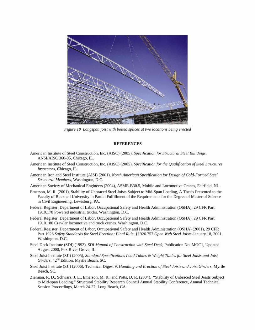
Figure 18 Longspan joist with bolted splices at two locations being erected
REFERENCES American Institute of Steel Construction, Inc. (AISC) (2005), Specification for Structural Steel Buildings,
ANSI/AISC 360-05, Chicago, IL. American Institute of Steel Construction, Inc. (AISC) (2005), Specification for the Qualification of Steel Structures
Inspectors, Chicago, IL. American Iron and Steel Institute (AISI) (2001), North American Specification for Design of Cold-Formed Steel
Structural Members, Washington, D.C. American Society of Mechanical Engineers (2004), ASME-B30.5, Mobile and Locomotive Cranes, Fairfield, NJ. Emerson, M. R. (2001), Stability of Unbraced Steel Joists Subject to Mid-Span Loading, A Thesis Presented to the
Faculty of Bucknell University in Partial Fulfillment of the Requirements for the Degree of Master of Science in Civil Engineering, Lewisburg, PA.
Federal Register, Department of Labor, Occupational Safety and Health Administration (OSHA), 29 CFR Part 1910.178 Powered industrial trucks. Washington, D.C.
Federal Register, Department of Labor, Occupational Safety and Health Administration (OSHA), 29 CFR Part 1910.180 Crawler locomotive and truck cranes. Washington, D.C.
Federal Register, Department of Labor, Occupational Safety and Health Administration (OSHA) (2001), 29 CFR Part 1926 Safety Standards for Steel Erection; Final Rule, §1926.757 Open Web Steel Joists-January 18, 2001, Washington, D.C.
Steel Deck Institute (SDI) (1992), SDI Manual of Construction with Steel Deck, Publication No. MOC1, Updated August 2000, Fox River Grove, IL.
Steel Joist Institute (SJI) (2005), Standard Specifications Load Tables & Weight Tables for Steel Joists and Joist Girders, 42nd Edition, Myrtle Beach, SC.
Steel Joist Institute (SJI) (2006), Technical Digest 9, Handling and Erection of Steel Joists and Joist Girders, Myrtle Beach, SC.
Ziemian, R. D., Schwarz, J. E., Emerson, M. R., and Potts, D. R. (2004). “Stability of Unbraced Steel Joists Subject to Mid-span Loading.” Structural Stability Research Council Annual Stability Conference, Annual Technical Session Proceedings, March 24-27, Long Beach, CA.