Embed Size (px)
Citation preview

NSF-Sponsored Workshop on Electric Energy Research and Education
Doha, Qatar December 13-16, 2009
The University of Minnesota Experience:Sustainable Electric Energy Systems
Research and Education
Ned Mohan, University of Minnesota
Financial Crisis, Energy Crisis and
Climate Change700 B$/yrProduction and
Consumption
Source: DOE
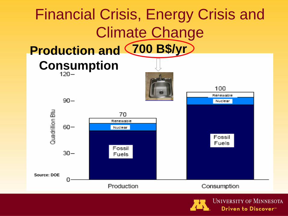
Electric Power Generation by Fuel
Type:
Source: DOE

Need and Challenges in
Workforce Development
( )a ( )b( )a ( )b
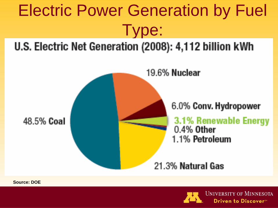
0 69010 60
VHz
34.5kV
161kV
Power ElectronicsConverters
V
Time0
60 Hz
Low-VoltageRide-Through
Generator
690V
Need for an Integrated
Curriculum
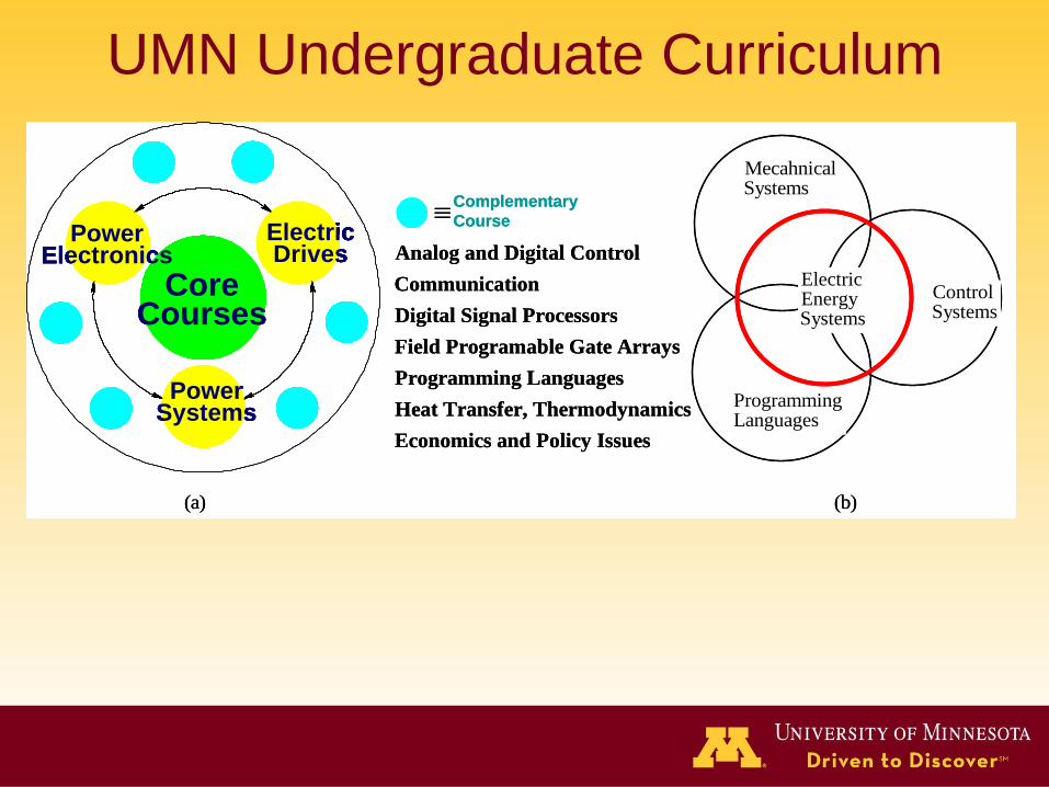
UMN Undergraduate Curriculum
Core Courses
Power Electronics
Electric Drives
Power Systems
Core Courses
Power Electronics
Electric Drives
Power Systems
(a) (b)
ElectricEnergySystems
ControlSystems
ProgrammingLanguages
MecahnicalSystems
Complementary
Course
Analog and Digital Control
Communication
Digital Signal Processors
Field Programable Gate Arrays
Programming Languages
Heat Transfer, Thermodynamics
Economics and Policy Issues
Core Courses
Power Electronics
Electric Drives
Power Systems
Core Courses
Power Electronics
Electric Drives
Power Systems
(a) (b)
ElectricEnergySystems
ControlSystems
ProgrammingLanguages
MecahnicalSystems
Complementary
Course
Analog and Digital Control
Communication
Digital Signal Processors
Field Programable Gate Arrays
Programming Languages
Heat Transfer, Thermodynamics
Economics and Policy Issues
( )a ( )b
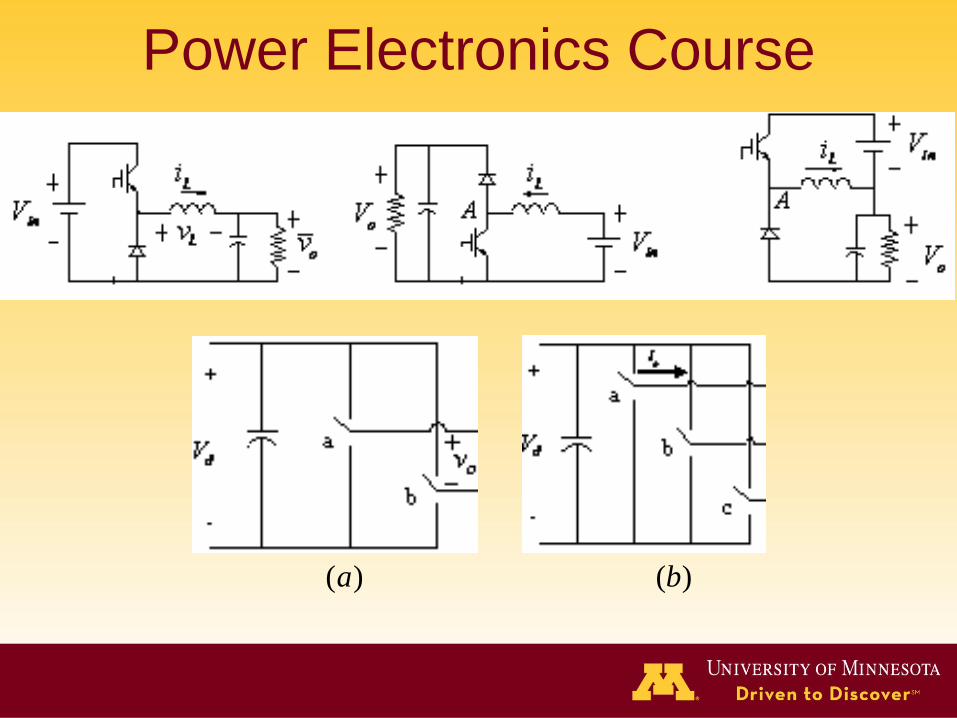
Power Electronics Course
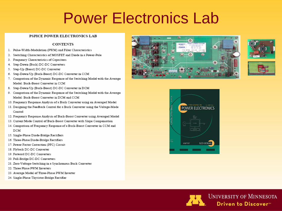
Power Electronics Lab
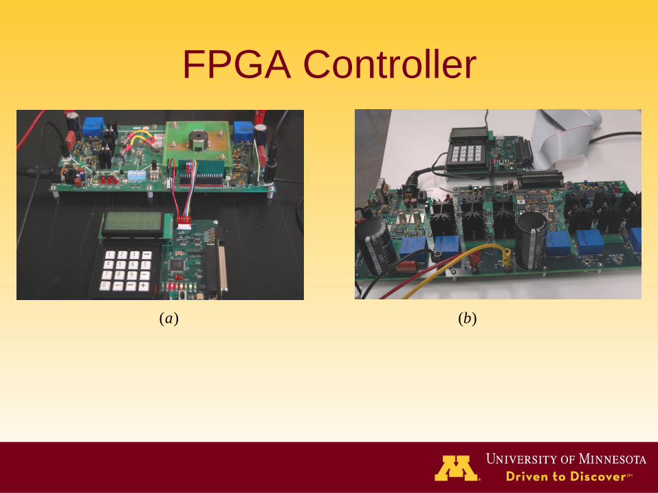
FPGA Controller
( )a ( )b
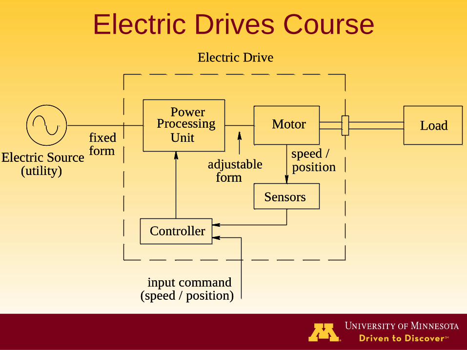
PowerProcessing
Unitfixedform
Electric Source(utility)
Controller
Electric Drive
adjustableform
Sensors
input command(speed / position)
Motor
speed /position
LoadPower
ProcessingUnitfixed
formElectric Source
(utility)
Controller
Electric Drive
adjustableform
Sensors
input command(speed / position)
Motor
speed /position
Load
Electric Drives Course
(b)
axisb
axisa
axisc
ci
bi
ai
Bis
s
sii BisB B
o120
o0
o240(a) (c)
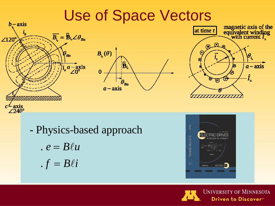
Fig. A-9 Space vector representation of sinusoidal flux density distribution.
axisa Bis
siB
0
( )si
B
ˆsI
at time tmagnetic axis of theequivalent winding
ˆwith current sI
axisa
si
si
(b)
axisb
axisa
axisc
ci
bi
ai
Bis
s
sii BisB B
o120
o0
o240
axisb
axisa
axisc
ci
bi
ai
Bis
s
sii BisB B
o120
o0
o240(a) (c)
Fig. A-9 Space vector representation of sinusoidal flux density distribution.
axisa Bis
siB
0
( )si
B
axisa Bis
siB
0
( )si
B
ˆsI
at time tmagnetic axis of theequivalent winding
ˆwith current sI
axisa
si
si
ˆsI
at time tmagnetic axis of theequivalent winding
ˆwith current sI
axisa
si
si
Fig. B-6 Space vector representation of sinusoidal flux density distribution. Fig. 11 Space-vector representation in ac machines.
(b)
axisb
axisa
axisc
ci
bi
ai
Bis
s
sii BisB B
o120
o0
o240(a) (c)
Fig. A-9 Space vector representation of sinusoidal flux density distribution.
axisa Bis
siB
0
( )si
B
ˆsI
at time tmagnetic axis of theequivalent winding
ˆwith current sI
axisa
si
si
(b)
axisb
axisa
axisc
ci
bi
ai
Bis
s
sii BisB B
o120
o0
o240
axisb
axisa
axisc
ci
bi
ai
Bis
s
sii BisB B
o120
o0
o240(a) (c)
Fig. A-9 Space vector representation of sinusoidal flux density distribution.
axisa Bis
siB
0
( )si
B
axisa Bis
siB
0
( )si
B
ˆsI
at time tmagnetic axis of theequivalent winding
ˆwith current sI
axisa
si
si
ˆsI
at time tmagnetic axis of theequivalent winding
ˆwith current sI
axisa
si
si
Fig. B-6 Space vector representation of sinusoidal flux density distribution.
(b)
axisb
axisa
axisc
ci
bi
ai
Bis
s
sii BisB B
o120
o0
o240(a) (c)
Fig. A-9 Space vector representation of sinusoidal flux density distribution.
axisa Bis
siB
0
( )si
B
ˆsI
at time tmagnetic axis of theequivalent winding
ˆwith current sI
axisa
si
si
(b)
axisb
axisa
axisc
ci
bi
ai
Bis
s
sii BisB B
o120
o0
o240
axisb
axisa
axisc
ci
bi
ai
Bis
s
sii BisB B
o120
o0
o240(a) (c)
Fig. A-9 Space vector representation of sinusoidal flux density distribution.
axisa Bis
siB
0
( )si
B
axisa Bis
siB
0
( )si
B
ˆsI
at time tmagnetic axis of theequivalent winding
ˆwith current sI
axisa
si
si
ˆsI
at time tmagnetic axis of theequivalent winding
ˆwith current sI
axisa
si
si
Fig. B-6 Space vector representation of sinusoidal flux density distribution. Fig. 11 Space-vector representation in ac machines.Fig. 12 Space vector representation in ac machines.
(b)
axisb
axisa
axisc
ci
bi
ai
Bis
s
sii BisB B
o120
o0
o240(a) (c)
Fig. A-9 Space vector representation of sinusoidal flux density distribution.
axisa Bis
siB
0
( )si
B
ˆsI
at time tmagnetic axis of theequivalent winding
ˆwith current sI
axisa
si
si
(b)
axisb
axisa
axisc
ci
bi
ai
Bis
s
sii BisB B
o120
o0
o240
axisb
axisa
axisc
ci
bi
ai
Bis
s
sii BisB B
o120
o0
o240(a) (c)
Fig. A-9 Space vector representation of sinusoidal flux density distribution.
axisa Bis
siB
0
( )si
B
axisa Bis
siB
0
( )si
B
ˆsI
at time tmagnetic axis of theequivalent winding
ˆwith current sI
axisa
si
si
ˆsI
at time tmagnetic axis of theequivalent winding
ˆwith current sI
axisa
si
si
Fig. B-6 Space vector representation of sinusoidal flux density distribution. Fig. 11 Space-vector representation in ac machines.
(b)
axisb
axisa
axisc
ci
bi
ai
Bis
s
sii BisB B
o120
o0
o240(a) (c)
Fig. A-9 Space vector representation of sinusoidal flux density distribution.
axisa Bis
siB
0
( )si
B
ˆsI
at time tmagnetic axis of theequivalent winding
ˆwith current sI
axisa
si
si
(b)
axisb
axisa
axisc
ci
bi
ai
Bis
s
sii BisB B
o120
o0
o240
axisb
axisa
axisc
ci
bi
ai
Bis
s
sii BisB B
o120
o0
o240(a) (c)
Fig. A-9 Space vector representation of sinusoidal flux density distribution.
axisa Bis
siB
0
( )si
B
axisa Bis
siB
0
( )si
B
ˆsI
at time tmagnetic axis of theequivalent winding
ˆwith current sI
axisa
si
si
ˆsI
at time tmagnetic axis of theequivalent winding
ˆwith current sI
axisa
si
si
Fig. B-6 Space vector representation of sinusoidal flux density distribution.
(b)
axisb
axisa
axisc
ci
bi
ai
Bis
s
sii BisB B
o120
o0
o240(a) (c)
Fig. A-9 Space vector representation of sinusoidal flux density distribution.
axisa Bis
siB
0
( )si
B
ˆsI
at time tmagnetic axis of theequivalent winding
ˆwith current sI
axisa
si
si
(b)
axisb
axisa
axisc
ci
bi
ai
Bis
s
sii BisB B
o120
o0
o240
axisb
axisa
axisc
ci
bi
ai
Bis
s
sii BisB B
o120
o0
o240(a) (c)
Fig. A-9 Space vector representation of sinusoidal flux density distribution.
axisa Bis
siB
0
( )si
B
axisa Bis
siB
0
( )si
B
ˆsI
at time tmagnetic axis of theequivalent winding
ˆwith current sI
axisa
si
si
ˆsI
at time tmagnetic axis of theequivalent winding
ˆwith current sI
axisa
si
si
Fig. B-6 Space vector representation of sinusoidal flux density distribution. Fig. 11 Space-vector representation in ac machines.
(b)
axisb
axisa
axisc
ci
bi
ai
Bis
s
sii BisB B
o120
o0
o240(a) (c)
Fig. A-9 Space vector representation of sinusoidal flux density distribution.
axisa Bis
siB
0
( )si
B
ˆsI
at time tmagnetic axis of theequivalent winding
ˆwith current sI
axisa
si
si
(b)
axisb
axisa
axisc
ci
bi
ai
Bis
s
sii BisB B
o120
o0
o240
axisb
axisa
axisc
ci
bi
ai
Bis
s
sii BisB B
o120
o0
o240(a) (c)
Fig. A-9 Space vector representation of sinusoidal flux density distribution.
axisa Bis
siB
0
( )si
B
axisa Bis
siB
0
( )si
B
ˆsI
at time tmagnetic axis of theequivalent winding
ˆwith current sI
axisa
si
si
ˆsI
at time tmagnetic axis of theequivalent winding
ˆwith current sI
axisa
si
si
Fig. B-6 Space vector representation of sinusoidal flux density distribution.
(b)
axisb
axisa
axisc
ci
bi
ai
Bis
s
sii BisB B
o120
o0
o240(a) (c)
Fig. A-9 Space vector representation of sinusoidal flux density distribution.
axisa Bis
siB
0
( )si
B
ˆsI
at time tmagnetic axis of theequivalent winding
ˆwith current sI
axisa
si
si
(b)
axisb
axisa
axisc
ci
bi
ai
Bis
s
sii BisB B
o120
o0
o240
axisb
axisa
axisc
ci
bi
ai
Bis
s
sii BisB B
o120
o0
o240(a) (c)
Fig. A-9 Space vector representation of sinusoidal flux density distribution.
axisa Bis
siB
0
( )si
B
axisa Bis
siB
0
( )si
B
ˆsI
at time tmagnetic axis of theequivalent winding
ˆwith current sI
axisa
si
si
ˆsI
at time tmagnetic axis of theequivalent winding
ˆwith current sI
axisa
si
si
Fig. B-6 Space vector representation of sinusoidal flux density distribution. Fig. 11 Space-vector representation in ac machines.Fig. 12 Space vector representation in ac machines.
Use of Space Vectors
- Physics-based approach
.
.
e B u
f B i
a axisstator
A axisrotor
d axis
m
isd
isq
q axisat t
i rq
ird
m
is
ir
3
2isd
3
2isq
3
2irq 3
2ird
d
d
da
dA
3
2sN
3
2sN
3
2sN
Figure 3-3 Stator and rotor mmf representation by
equivalent dq winding currents.
a axisa axisstator
A axisA axisrotor
d axisd axis
m
m
isdisd
isqisq
q axisq axisat tat t
i rqi rq
irdird
m
m
is
is
ir
ir
3
2isd
3
2isd
3
2isq
3
2isq
3
2irq
3
2irq 3
2ird
3
2ird
d
d
da
dA
3
2sN
3
2sN
3
2sN
Figure 3-3 Stator and rotor mmf representation by
equivalent dq winding currents.Figure 3-3 Stator and rotor representation by equivalent dq winding currents. The
dq winding voltages are defined as positive at the dotted terminals.
Note that the relative positions of the stator and the rotor current
space vectors are not actual, rather only for definition purposes.
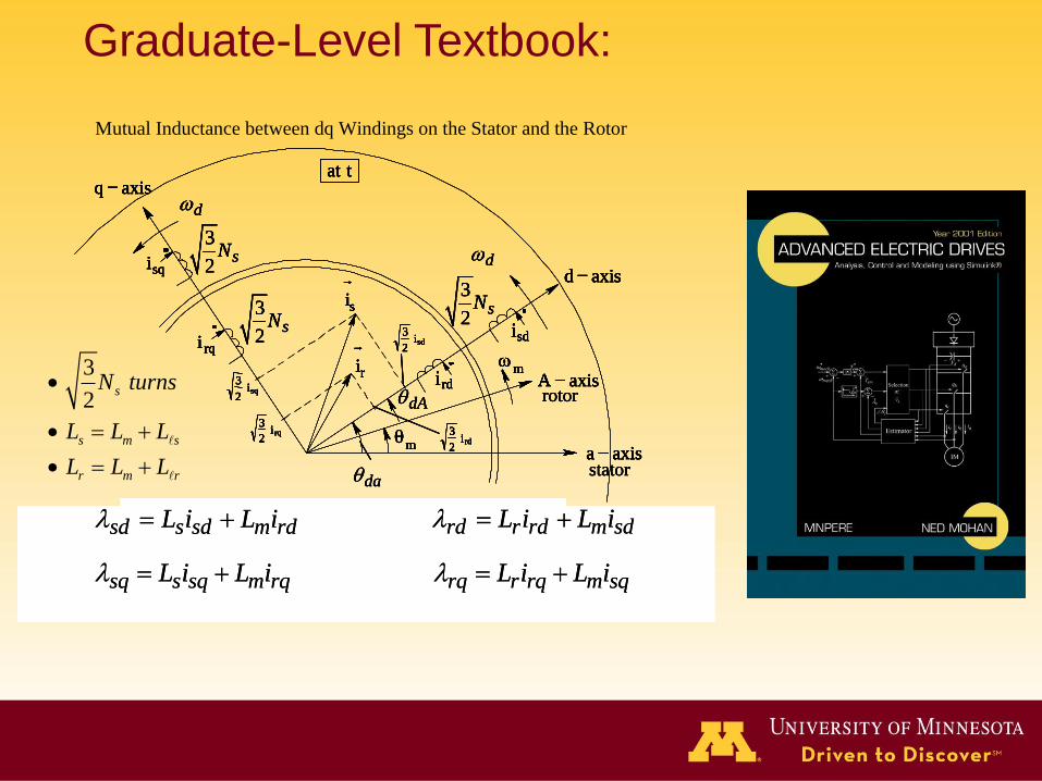
Mutual Inductance between dq Windings on the Stator and the Rotor
sd s sd m rdL i L i
sq s sq m rqL i L i
rd r rd m sdL i L i
rq r rq m sqL i L i
sd s sd m rdL i L i
sq s sq m rqL i L i
rd r rd m sdL i L i
rq r rq m sqL i L i
3
2s
s m s
r m r
N turns
L L L
L L L
Graduate-Level Textbook:
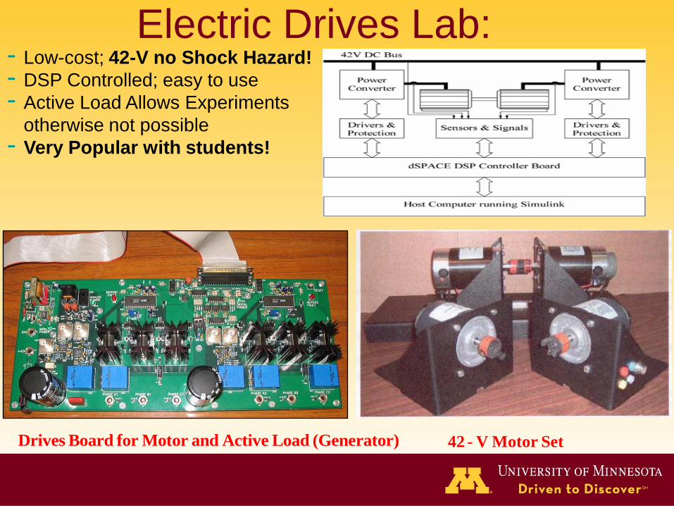
Drives Board for Motor and Active Load (Generator) 42 - V Motor Set
Electric Drives Lab:- Low-cost; 42-V no Shock Hazard!
- DSP Controlled; easy to use
- Active Load Allows Experiments
otherwise not possible
- Very Popular with students!
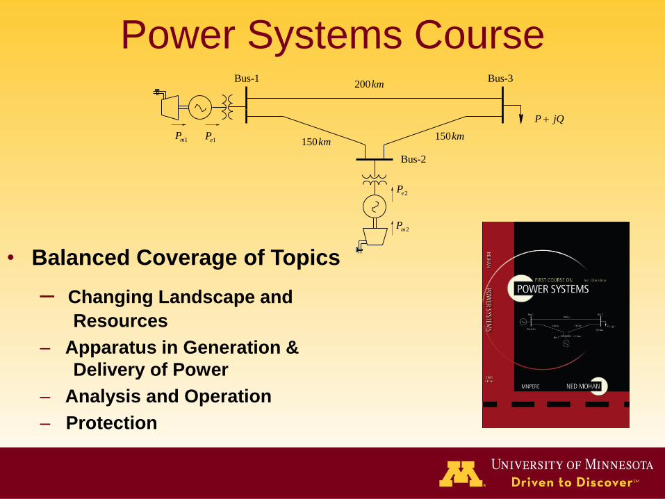
Bus-1 Bus-3
Bus-2
1mP1eP
2mP
2eP
P jQ
200km
150km150km
Power Systems Course
• Balanced Coverage of Topics
– Changing Landscape and
Resources
– Apparatus in Generation &
Delivery of Power
– Analysis and Operation
– Protection
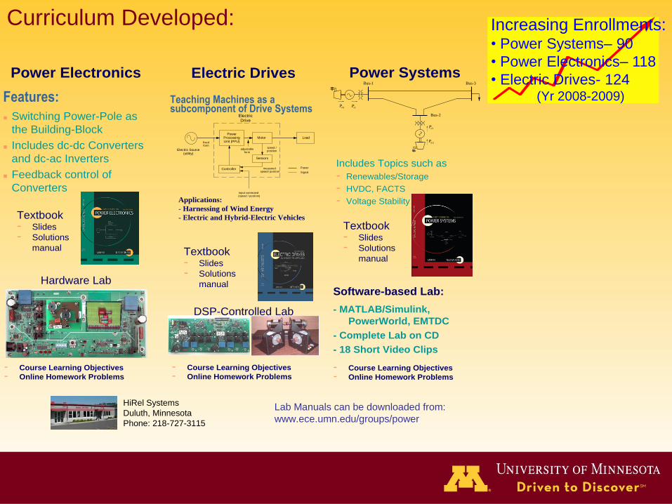
Curriculum Developed:
Bus-1 Bus-3
Bus-2
1mP1eP
2mP
2eP
Software-based Lab:
- MATLAB/Simulink,
PowerWorld, EMTDC
- Complete Lab on CD
- 18 Short Video Clips
- Course Learning Objectives
- Online Homework Problems
Textbook- Slides
- Solutions
manual
Power Systems
Includes Topics such as
- Renewables/Storage
- HVDC, FACTS
- Voltage Stability
Teaching Machines as a subcomponent of Drive Systems
Power Processing Unit (PPU)fixed
form
measured speed/ position
speed /position
Motor
Electric Drive
Load
input command (speed / position)
Power
Signal
adjustable form
Electric Source(utility)
Sensors
Controller
Applications:
- Harnessing of Wind Energy
- Electric and Hybrid-Electric Vehicles
Textbook- Slides
- Solutions
manual
DSP-Controlled Lab
- Course Learning Objectives
- Online Homework Problems
Electric Drives
Features:
Switching Power-Pole as
the Building-Block
Includes dc-dc Converters
and dc-ac Inverters
Feedback control of
Converters
Textbook- Slides
- Solutions
manual
Hardware Lab
- Course Learning Objectives
- Online Homework Problems
Power Electronics
HiRel Systems
Duluth, Minnesota
Phone: 218-727-3115
Lab Manuals can be downloaded from:
www.ece.umn.edu/groups/power
Increasing Enrollments:• Power Systems– 90
• Power Electronics– 118
• Electric Drives- 124(Yr 2008-2009)
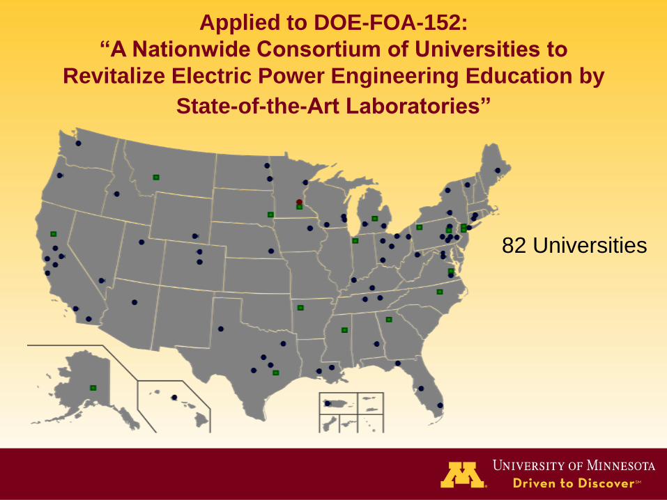
Applied to DOE-FOA-152:
“A Nationwide Consortium of Universities to
Revitalize Electric Power Engineering Education by
State-of-the-Art Laboratories”
82 Universities


Thank You!


![ELECTRIC DRIVES [NED MOHAN 2001 -(Scanned) 470pág]](https://img.pdfslide.us/doc/110x75/5474d602b4af9f914e8b458a/electric-drives-ned-mohan-2001-scanned-470pag.jpg)