Embed Size (px)
Citation preview
Nepal Electricity Authority Nepal
Nationwide Master Plan Study on
Storage-type Hydroelectric Power Development in Nepal
Final Report
Appendix (1/2)
February 2014
Japan International Cooperation Agency
Electric Power Development Co., Ltd.
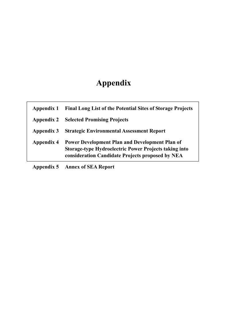
Appendix
Appendix 1 Final Long List of the Potential Sites of Storage Projects
Appendix 2 Selected Promising Projects
Appendix 3 Strategic Environmental Assessment Report
Appendix 4 Power Development Plan and Development Plan of Storage-type Hydroelectric Power Projects taking into consideration Candidate Projects proposed by NEA
Appendix 5 Annex of SEA Report

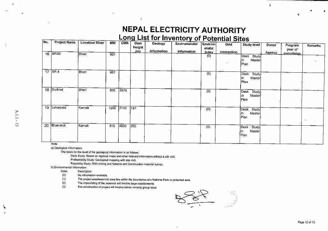
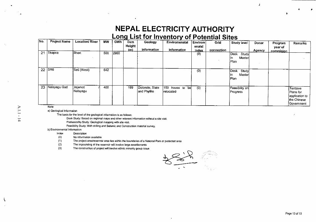
Appendix-1 Final Long List of the Potential Sites of Storage Projects
1.1 Final long list of potential sites of storage projects
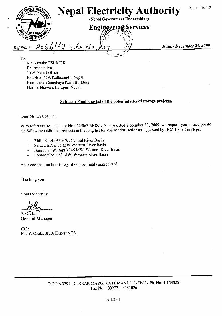
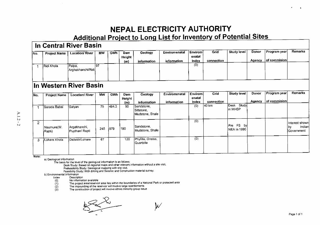
1.2 Final long list of the potential sites of storage projects (additional)
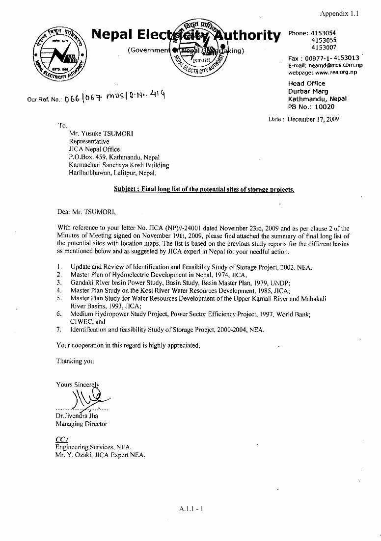
Appendix 1.1
A.1.1 - 1
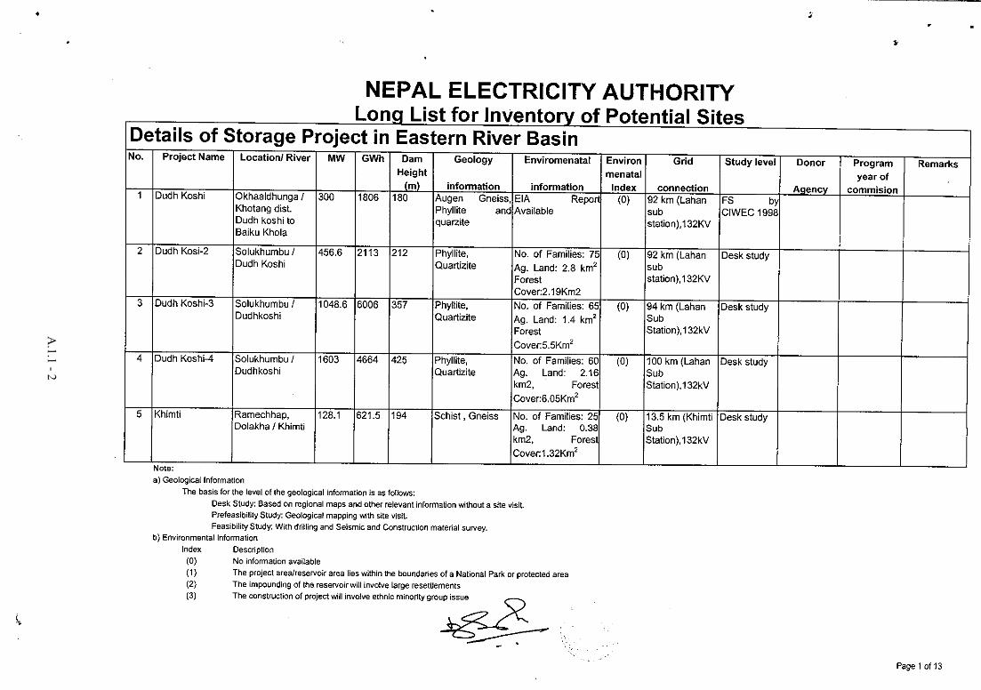
A.1.1 - 2
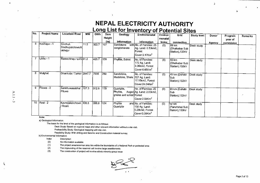
A.1.1 - 3
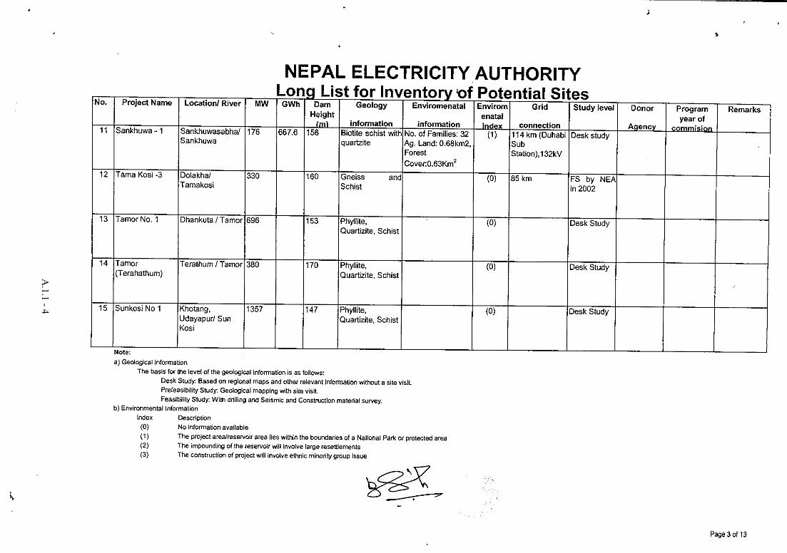
A.1.1 - 4
A.1.1 - 5
A.1.1 - 6
A.1.1 - 7
A.1.1 - 8
A.1.1 - 9
A.1.1 - 10
A.1.1 - 11
A.1.1 - 12
A.1.1 - 13
A.1.1 - 14
Appendix 1.2
A.1.2 - 1
A.1.2 - 2

Appendix 2 Selected Promising Projects
2.1 Dudh Koshi (E-01) 2.2 Kokhajor-1 (E-06) 2.3 Sun Koshi No.3 (E-17) 2.4 Lower Badigad (C-02) 2.5 Andhi Khola (C-08) 2.6 Chera-1 (W-02) 2.7 Lower Jhimruk (W-05) 2.8 Madi (W-06) 2.9 Nalsyau Gad (W-23) 2.10 Naumure (W.Rapti) (W-25)
Nationwide Master Plan Study on Storage-type Hydroelectric Power Development in Nepal
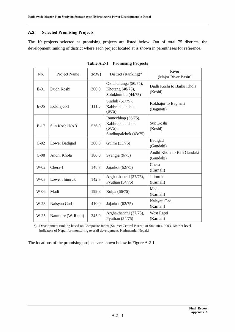
A.2 Selected Promising Projects
The 10 projects selected as promising projects are listed below. Out of total 75 districts, the development ranking of district where each project located at is shown in parentheses for reference.
Table A.2-1 Promising Projects
No. Project Name (MW) District (Ranking)* River
(Major River Basin)
E-01 Dudh Koshi 300.0 Okhaldhunga (50/75), Khotang (48/75), Solukhumbu (44/75)
Dudh Koshi to Baiku Khola (Koshi)
E-06 Kokhajor-1 111.5 Sinduli (51/75), Kabhrepalanchok (6/75)
Kokhajor to Bagmati (Bagmati)
E-17 Sun Koshi No.3 536.0
Ramechhap (56/75), Kabhrepalanchok (6/75), Sindhupalchok (43/75)
Sun Koshi (Koshi)
C-02 Lower Badigad 380.3 Gulmi (33/75) Badigad (Gandaki)
C-08 Andhi Khola 180.0 Syangja (9/75) Andhi Khola to Kali Gandaki (Gandaki)
W-02 Chera-1 148.7 Jajarkot (62/75) Chera (Karnali)
W-05 Lower Jhimruk 142.5 Arghakhanchi (27/75), Pyuthan (54/75)
Jhimruk (Karnali)
W-06 Madi 199.8 Rolpa (66/75) Madi (Karnali)
W-23 Nalsyau Gad 410.0 Jajarkot (62/75) Nalsyau Gad (Karnali)
W-25 Naumure (W. Rapti) 245.0 Arghakhanchi (27/75), Pyuthan (54/75)
West Rapti (Karnali)
*): Development ranking based on Composite Index (Source: Central Bureau of Statistics. 2003. District level indicators of Nepal for monitoring overall development. Kathmandu, Nepal.)
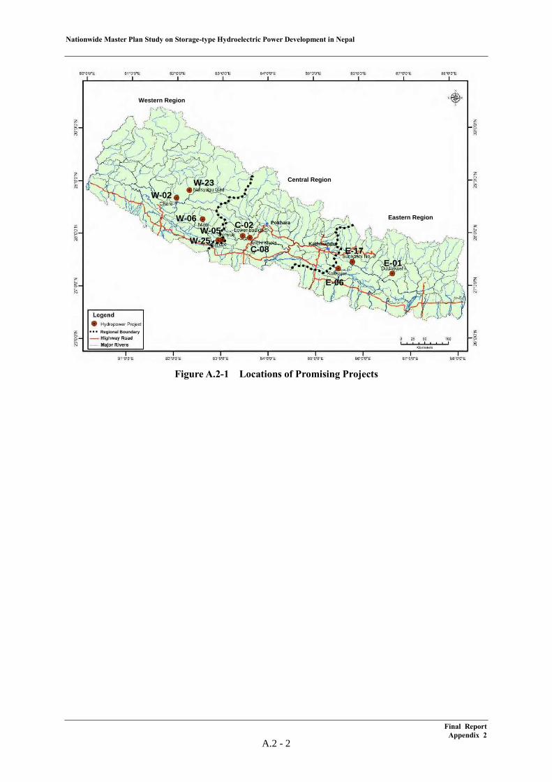
The locations of the promising projects are shown below in Figure A.2-1.
Final Report Appendix 2
A.2 - 1
Nationwide Master Plan Study on Storage-type Hydroelectric Power Development in Nepal
Figure A.2-1 Locations of Promising Projects
Western Region
Central Region
Eastern RegionPokhara
Kathmandu
Regional Boundary
W-23W-02
W-06
W-25W-05 C-02
C-08E-01
E-17
E-06
Western Region
Central Region
Eastern RegionPokhara
Kathmandu
Regional BoundaryRegional Boundary
W-23W-02
W-06
W-25W-05 C-02
C-08E-01
E-17
E-06
Final Report Appendix 2
A.2 - 2
Nationwide Master Plan Study on Storage-type Hydroelectric Power Development in Nepal
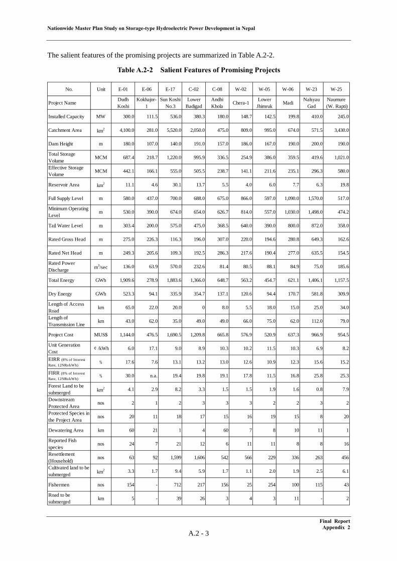
The salient features of the promising projects are summarized in Table A.2-2.
Table A.2-2 Salient Features of Promising Projects
No. Unit E-01 E-06 E-17 C-02 C-08 W-02 W-05 W-06 W-23 W-25
Project NameDudhKoshi
Kokhajor-1
Sun KoshiNo.3
LowerBadigad
AndhiKhola
Chera-1Lower
JhimrukMadi
NalsyauGad
Naumure (W. Rapti)
Installed Capacity MW 300.0 111.5 536.0 380.3 180.0 148.7 142.5 199.8 410.0 245.0
Catchment Area km2 4,100.0 281.0 5,520.0 2,050.0 475.0 809.0 995.0 674.0 571.5 3,430.0
Dam Height m 180.0 107.0 140.0 191.0 157.0 186.0 167.0 190.0 200.0 190.0
Total StorageVolume
MCM 687.4 218.7 1,220.0 995.9 336.5 254.9 386.0 359.5 419.6 1,021.0
Effective StorageVolume
MCM 442.1 166.1 555.0 505.5 238.7 141.1 211.6 235.1 296.3 580.0
Reservoir Area km2 11.1 4.6 30.1 13.7 5.5 4.0 6.0 7.7 6.3 19.8
Full Supply Level m 580.0 437.0 700.0 688.0 675.0 866.0 597.0 1,090.0 1,570.0 517.0
Minimum OperatingLevel
m 530.0 390.0 674.0 654.0 626.7 814.0 557.0 1,030.0 1,498.0 474.2
Tail Water Level m 303.4 200.0 575.0 475.0 368.5 640.0 390.0 800.0 872.0 358.0
Rated Gross Head m 275.0 226.3 116.3 196.0 307.0 220.0 194.6 280.8 649.3 162.6
Rated Net Head m 249.3 205.6 109.3 192.5 286.3 217.6 190.4 277.0 635.5 154.5
Rated PowerDischarge m3/sec 136.0 63.9 570.0 232.6 81.4 80.5 88.1 84.9 75.0 185.6
Total Energy GWh 1,909.6 278.9 1,883.6 1,366.0 648.7 563.2 454.7 621.1 1,406.1 1,157.5
Dry Energy GWh 523.3 94.1 335.9 354.7 137.1 120.6 94.4 170.7 581.8 309.9
Length of AccessRoad
km 65.0 22.0 20.0 0 8.0 5.5 18.0 15.0 25.0 34.0
Length ofTransmission Line
km 43.0 62.0 35.0 49.0 49.0 66.0 75.0 62.0 112.0 79.0
Project Cost MUS$ 1,144.0 476.5 1,690.5 1,209.8 665.8 576.9 520.9 637.3 966.9 954.5
Unit GenerationCost
¢/kWh 6.0 17.1 9.0 8.9 10.3 10.2 11.5 10.3 6.9 8.2
EIRR (8% of InterestRate, 12NRs/kWh) % 17.6 7.6 13.1 13.2 13.0 12.6 10.9 12.3 15.6 15.2
FIRR (8% of InterestRate, 12NRs/kWh) % 30.0 n.a. 19.4 19.8 19.1 17.8 11.5 16.8 25.8 25.3
Forest Land to besubmerged km2 4.1 2.9 8.2 3.3 1.5 1.5 1.9 1.6 0.8 7.9
DownstreamProtected Area
nos 2 1 2 3 3 3 2 2 3 2
Protected Species inthe Project Area
nos 20 11 18 17 15 16 19 15 8 20
Dewatering Area km 60 21 1 4 60 7 8 10 11 1
Reported Fishspecies
nos 24 7 21 12 6 11 11 8 8 16
Resettlement(Household)
nos 63 92 1,599 1,606 542 566 229 336 263 456
Cultivated land to besubmerged km2 3.3 1.7 9.4 5.9 1.7 1.1 2.0 1.9 2.5 6.1
Fishermen nos 154 - 712 217 156 25 254 100 115 43
Road to besubmerged
km 5 - 39 26 3 4 3 11 - 2
Final Report Appendix 2
A.2 - 3
Nationwide Master Plan Study on Storage-type Hydroelectric Power Development in Nepal
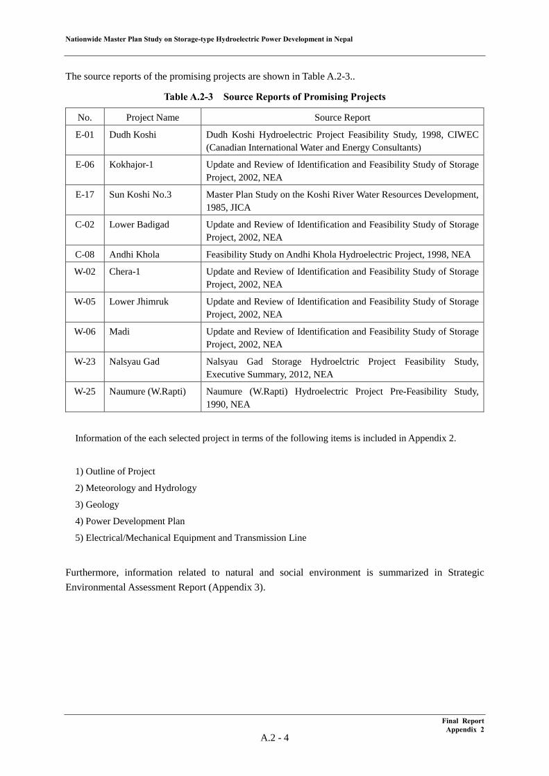
The source reports of the promising projects are shown in Table A.2-3..
Table A.2-3 Source Reports of Promising Projects
No. Project Name Source Report
E-01 Dudh Koshi Dudh Koshi Hydroelectric Project Feasibility Study, 1998, CIWEC (Canadian International Water and Energy Consultants)
E-06 Kokhajor-1 Update and Review of Identification and Feasibility Study of Storage Project, 2002, NEA
E-17 Sun Koshi No.3 Master Plan Study on the Koshi River Water Resources Development, 1985, JICA
C-02 Lower Badigad Update and Review of Identification and Feasibility Study of Storage Project, 2002, NEA
C-08 Andhi Khola Feasibility Study on Andhi Khola Hydroelectric Project, 1998, NEA
W-02 Chera-1 Update and Review of Identification and Feasibility Study of Storage Project, 2002, NEA
W-05 Lower Jhimruk Update and Review of Identification and Feasibility Study of Storage Project, 2002, NEA
W-06 Madi Update and Review of Identification and Feasibility Study of Storage Project, 2002, NEA
W-23 Nalsyau Gad Nalsyau Gad Storage Hydroelctric Project Feasibility Study, Executive Summary, 2012, NEA
W-25 Naumure (W.Rapti) Naumure (W.Rapti) Hydroelectric Project Pre-Feasibility Study, 1990, NEA
Information of the each selected project in terms of the following items is included in Appendix 2.
1) Outline of Project
2) Meteorology and Hydrology
3) Geology
4) Power Development Plan
5) Electrical/Mechanical Equipment and Transmission Line
Furthermore, information related to natural and social environment is summarized in Strategic Environmental Assessment Report (Appendix 3).
Final Report Appendix 2
A.2 - 4

2.1 Dudh Koshi Project (E-01)
Nationwide Master Plan Study on Storage-type Hydroelectric Power Development in Nepal
Table of Contents
(1) Project Summary ................................................................................................................... 1 (2) Meteorology & Hydrology .................................................................................................... 6 (3) Geology ................................................................................................................................. 10
(4) Development Plan ................................................................................................................. 14 (5) Electrical/Mechanical Equipment and Transmission Line .................................................... 21
List of Tables
Table A.2.1-1 Project Description ................................................................................................ 4 Table A.2.1-2 Monthly Rainfall at the Okhaldhunga Station ....................................................... 6 Table A.2.1-3 Monthly Rainfall at the Khotang Station ............................................................... 6 Table A.2.1-4 Flow Data of the Dudh Koshi Project .................................................................... 7 Table A.2.1-5 List of Potentially Critical Glacial Lakes in Nepal as of 2007 .............................. 8 Table A.2.1-6 List of Potentially Critical Glacial Lakes in the Dudh Koshi Bain as of 2010 ...... 8 Table A.2.1-7 List of Potentially Critical Glacial Lakes for the Dudh Koshi Project .................. 9 Table A.2.1-8 Life of Reservoir .................................................................................................... 10 Table A.2.1-9 Salient Features of Project ..................................................................................... 14
List of Figures
Figure A.2.1-1 Location of the Dudh Koshi Project (E-01) ......................................................... 3 Figure A.2.1-2 General Layout of the Dudh Koshi Project (E-01) .............................................. 3 Figure A.2.1-3 Land Use and Buildings in the Reservoir Area of the Dudh Koshi Project ......... 5 Figure A.2.1-4 Location of potentially critical glacial lakes in the Dudh Koshi project .............. 9 Figure A.2.1-5 Geological map of the project area ...................................................................... 12 Figure A.2.1-6 Geological section of dam site ............................................................................. 13 Figure A.2.1-7 Geological profile along headrace tunnel ............................................................ 13 Figure A.2.1-8 General Layout ..................................................................................................... 15 Figure A.2.1-9 Dam Plan .............................................................................................................. 16 Figure A.2.1-10 Dam Section ....................................................................................................... 17 Figure A.2.1-11 Powerhouse Plan ................................................................................................ 18 Figure A.2.1-12 Powerhouse Section ........................................................................................... 19
Final Report Appendix 2.1
Nationwide Master Plan Study on Storage-type Hydroelectric Power Development in Nepal
A.2.1 Dudh Koshi (E-01)
(1) Project Summary
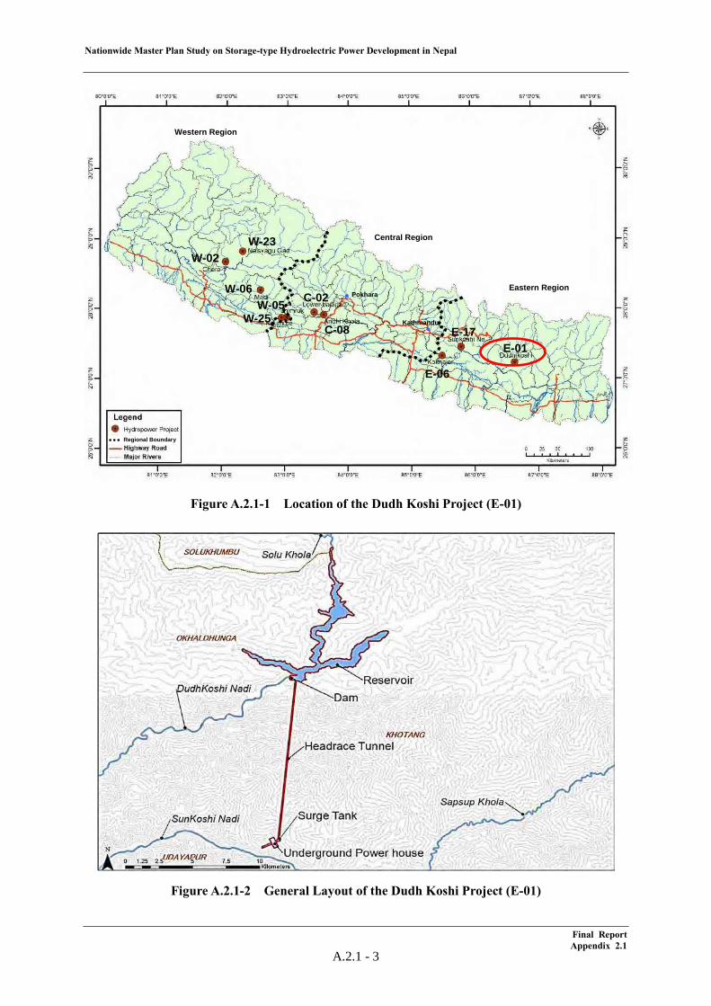
The Dudh Koshi Project is a 300 MW storage-type hydroelectric power project located in the Okhaldhunga, Khotang and Solukhumbu Districts in the eastern region. The intake is located at the Dudh Koshi river and the outlet is located at the Baiku Khola river. This project was originally discovered in the “Master Plan Study on the Koshi River Water Resources Development, 1985” carried out by JICA. After that, the “Dudh Koshi Hydroelectric Project Feasibility Study” was carried out by CIWEC (Canadian International Water and Energy Consultants) and the study results were summarized in the report in 1998.
Further, the JICA Study Team conducted a site reconnaissance at the Dudh Koshi project site in June 2012. The findings attained through site reconnaissance are also summarized in this clause.
As hydrological characteristics, the annual rainfall at the Okhaldhunga gauging station nearest to the project site is 1,774 mm and the average river discharge at the dam site is significant, 224 m3/s. The catchment area is 4,100 km2, and the specific sediment volume is estimated to be 2,540 t/km2/year. This is smaller than the 3,300 t/km2/year value adopted by the NEA as an average specific sedimentation volume in the eastern region. It has to be noted that three glacier lakes having a high risk of a GLOF are identified in the drainage basin.
From a geological view point, the project area lies in the Lesser Himalaya Zone and is composed mainly of phyllite, quartzite, schist and gneiss. The reservoir area is underlain mainly by phyllite. This area is water tight and slopes in its surrounding area are stable. The dam site is underlain by quartzite and phyllite, which form relatively permeable rock. The headrace tunnel route passes phyllite, quartzite, schist, gneiss and three major local faults. The portions of overburden of more than about 1,000 m and crossing faults would need strong tunnel support. The underground power house is located in hard and compact gneiss rock. The project area is located in the area where a large acceleration of 240 mgal is shown on the seismic hazard map. However, it is away from large tectonic thrusts at a long distance of 26 km and from epicenters of larger than M4 at a relatively long distance of 10 km.
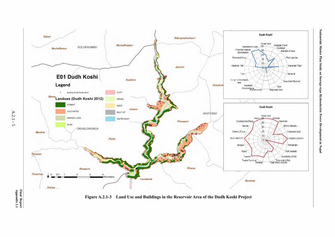
From the view point of the natural and social environment, the impact on the Natural Environment is relatively high and impact on the Social Environment is average. The Dudh Koshi Project is located in the Koshi river basin and the reservoir area is 11.1 km2. The number of recorded plants is 67, which is the highest next to the Madi Project. The number of recorded fauna is relatively high, with numbers such as 24 mammals, 51 birds, and 17 Herpetofauna. The number of fish species is the highest, which is 24. The length of the dewatering area is 60km, which is the longest together with the Andhi Khola Project. The length of the Transmission Line is 43km, which is relatively short. The number of resettlements is the lowest, which is 63, and the number of resettlements per unit of generation power is also the lowest, around 0.21 HH/MW. The affected irrigation scheme is one which is relatively low. Rafting activities are found in the reservoir area. There is no development plan in the reservoir area. The Indigenous groups in the reservoir area are Newar (Advanced), Magar (Disadvantaged), Tamang (Disadvantaged) and Majhi (Marginalised).
From the view point of hydropower planning, two alternatives are compared in terms of layout in FS. One is a layout that has a rockfill dam and headrace tunnel of 13.3 km conducting water
Final Report Appendix 2.1
A.2.1 - 1
Nationwide Master Plan Study on Storage-type Hydroelectric Power Development in Nepal
to the powerhouse with 127.35 m of a water head. The other is a layout that has a concrete gravity dam and powerhouse located at the left bank immediately downstream of the dam site. FS concludes that the layout of the rockfill dam and headrace tunnel is more economical. Although inflow into the Kurule dam, which diverts river water from the Sun Koshi river to the Kamala river for irrigation and hydropower projects in Sun Koshi Multipurpose Scheme (Phase I) would decrease since the Kurule dam is located upstream of the outlet of the Dudh Koshi project, it is concluded that there would be no adverse effect because the necessary water volume could be secured for the projects. Further, FS also concludes that the flood volume of a GLOF is less than that of a PMF and can be controlled to flow down safely by installing an emergency spillway, assuming the case that the main spillway gates are out of order. However, a sand flushing facility such as that adopted in the Tanahu project, which enables flushing out the sediment produced by a GLOF has to be studied, since several glacier lakes having potential risk of a GLOF exist upstream of the Dudh Koshi project. The dam type that enables installation of such a sand flushing facility in the dam also has to be studied.
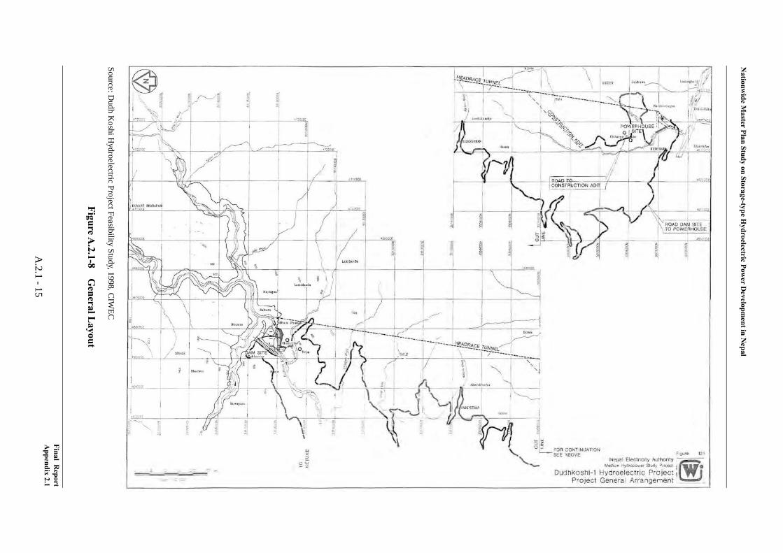
The location, basic layout and salient features of the project are shown below.
Final Report Appendix 2.1
A.2.1 - 2
Nationwide Master Plan Study on Storage-type Hydroelectric Power Development in Nepal
Figure A.2.1-1 Location of the Dudh Koshi Project (E-01)
Figure A.2.1-2 General Layout of the Dudh Koshi Project (E-01)
Western Region
Central Region
Eastern RegionPokhara
Kathmandu
Regional Boundary
W-23W-02
W-06
W-25W-05 C-02
C-08E-01
E-17
E-06
Western Region
Central Region
Eastern RegionPokhara
Kathmandu
Regional BoundaryRegional Boundary
W-23W-02
W-06
W-25W-05 C-02
C-08E-01
E-17
E-06
Final Report Appendix 2.1
A.2.1 - 3
Nationwide Master Plan Study on Storage-type Hydroelectric Power Development in Nepal
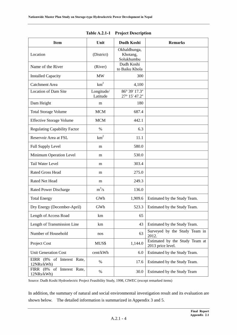
Table A.2.1-1 Project Description
Item Unit Dudh Koshi Remarks
Location (District) Okhaldhunga,
Khotang, Solukhumbu
Name of the River (River) Dudh Koshi to Baiku Khola
Installed Capacity MW 300
Catchment Area km2 4,100 Location of Dam Site
Longitude/ Latitude
86° 39' 17.3'' 27° 15' 47.2''
Dam Height m 180
Total Storage Volume MCM 687.4
Effective Storage Volume MCM 442.1
Regulating Capability Factor % 6.3
Reservoir Area at FSL km2 11.1
Full Supply Level m 580.0
Minimum Operation Level m 530.0
Tail Water Level m 303.4
Rated Gross Head m 275.0
Rated Net Head m 249.3
Rated Power Discharge m3/s 136.0
Total Energy GWh 1,909.6 Estimated by the Study Team.
Dry Energy (December-April) GWh 523.3 Estimated by the Study Team.
Length of Access Road km 65
Length of Transmission Line km 43 Estimated by the Study Team.
Number of Household nos 63 Surveyed by the Study Team in 2012.
Project Cost MUS$ 1,144.0 Estimated by the Study Team at 2013 price level.
Unit Generation Cost cent/kWh 6.0 Estimated by the Study Team. EIRR (8% of Interest Rate, 12NRs/kWh) % 17.6 Estimated by the Study Team.
FIRR (8% of Interest Rate, 12NRs/kWh) % 30.0 Estimated by the Study Team
Source: Dudh Koshi Hydroelectric Project Feasibility Study, 1998, CIWEC (except remarked items) In addition, the summary of natural and social environmental investigation result and its evaluation are shown below. The detailed information is summarized in Appendix 3 and 5.
Final Report Appendix 2.1
A.2.1 - 4
Nationw
ide Master Plan Study on Storage-type H
ydroelectric Power D
evelopment in N
epal
Final Report
Appendix 2.1
A.2.1 -5
Figure A.2.1-3 Land Use and Buildings in the Reservoir Area of the Dudh Koshi Project
Nationwide Master Plan Study on Storage-type Hydroelectric Power Development in Nepal
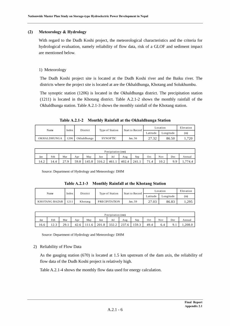
(2) Meteorology & Hydrology
With regard to the Dudh Koshi project, the meteorological characteristics and the criteria for hydrological evaluation, namely reliability of flow data, risk of a GLOF and sediment impact are mentioned below.
1) Meteorology
The Dudh Koshi project site is located at the Dudh Koshi river and the Baiku river. The districts where the project site is located at are the Okhaldhunga, Khotang and Solukhumbu.
The synoptic station (1206) is located in the Okhaldhunga district. The precipitation station (1211) is located in the Khotang district. Table A.2.1-2 shows the monthly rainfall of the Okhaldhunga station. Table A.2.1-3 shows the monthly rainfall of the Khotang station.
Table A.2.1-2 Monthly Rainfall at the Okhaldhunga Station
Source: Department of Hydrology and Meteorology: DHM
Table A.2.1-3 Monthly Rainfall at the Khotang Station
Source: Department of Hydrology and Meteorology: DHM
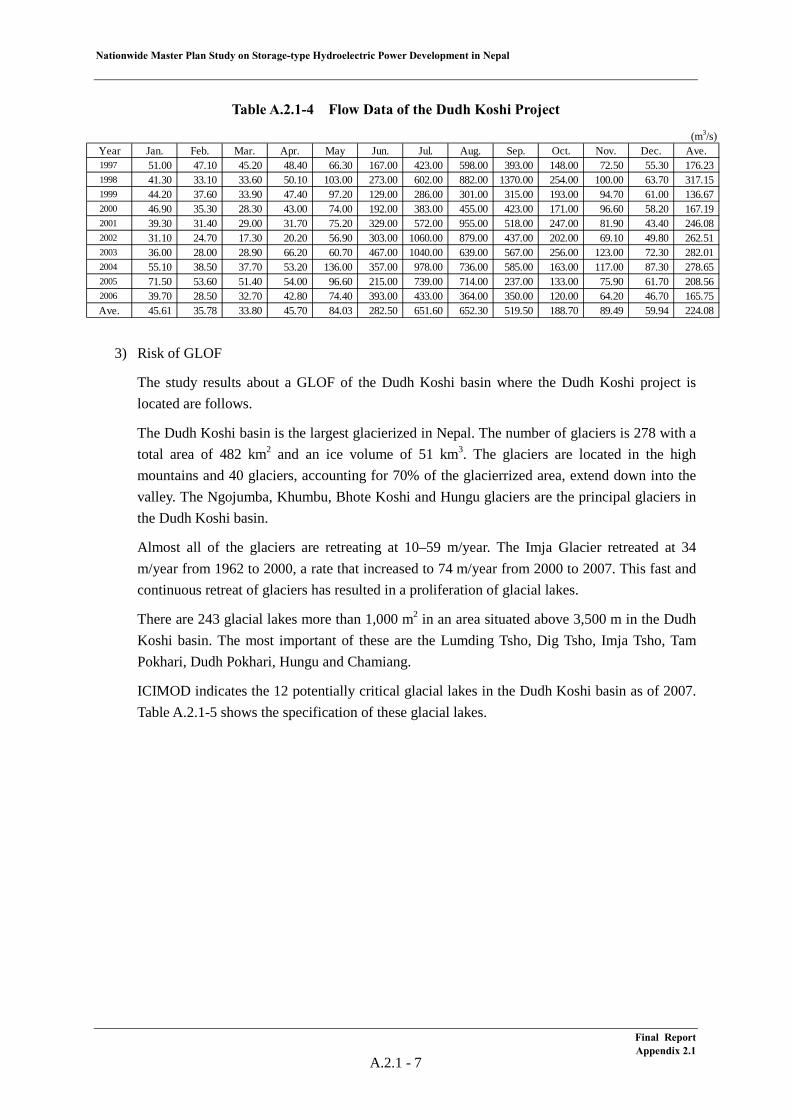
2) Reliability of Flow Data
As the gauging station (670) is located at 1.5 km upstream of the dam axis, the reliability of flow data of the Dudh Koshi project is relatively high.
Table A.2.1-4 shows the monthly flow data used for energy calculation.
Elevation
Latitude Longitude (m)
OKHALDHUNGA 1206 Okhaldhunga SYNOPTIC Jan, 56 27.32 86.50 1,720
Name Index DistrictLocation
Type of Station Start to Record
Jan Feb Mar Apr May Jun Jul Aug Sep Oct Nov Dec Annual
14.2 14.4 27.9 59.8 145.8 316.2 461.1 402.4 241.1 71.4 10.2 9.9 1,774.4
Precipitation (mm)
Elevation
Latitude Longitude (m)
KHOTANG BAZAR 1211 Khotang PRECIPITATION Jan, 59 27.03 86.83 1,295
Name Index DistrictLocation
Start to RecordType of Station
Jan Feb Mar Apr May Jun Jul Aug Sep Oct Nov Dec Annual
16.6 12.3 29.1 42.6 111.6 201.8 332.2 237.6 159.3 49.4 6.4 9.1 1,208.0
Precipitation (mm)
Final Report Appendix 2.1
A.2.1 - 6
Nationwide Master Plan Study on Storage-type Hydroelectric Power Development in Nepal
Table A.2.1-4 Flow Data of the Dudh Koshi Project
3) Risk of GLOF
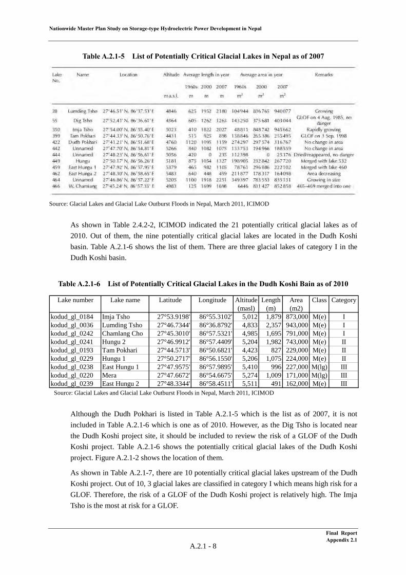
The study results about a GLOF of the Dudh Koshi basin where the Dudh Koshi project is located are follows.
The Dudh Koshi basin is the largest glacierized in Nepal. The number of glaciers is 278 with a total area of 482 km2 and an ice volume of 51 km3. The glaciers are located in the high mountains and 40 glaciers, accounting for 70% of the glacierrized area, extend down into the valley. The Ngojumba, Khumbu, Bhote Koshi and Hungu glaciers are the principal glaciers in the Dudh Koshi basin.
Almost all of the glaciers are retreating at 10–59 m/year. The Imja Glacier retreated at 34 m/year from 1962 to 2000, a rate that increased to 74 m/year from 2000 to 2007. This fast and continuous retreat of glaciers has resulted in a proliferation of glacial lakes.
There are 243 glacial lakes more than 1,000 m2 in an area situated above 3,500 m in the Dudh Koshi basin. The most important of these are the Lumding Tsho, Dig Tsho, Imja Tsho, Tam Pokhari, Dudh Pokhari, Hungu and Chamiang.
ICIMOD indicates the 12 potentially critical glacial lakes in the Dudh Koshi basin as of 2007. Table A.2.1-5 shows the specification of these glacial lakes.
(m3/s)Year Jan. Feb. Mar. Apr. May Jun. Jul. Aug. Sep. Oct. Nov. Dec. Ave.1997 51.00 47.10 45.20 48.40 66.30 167.00 423.00 598.00 393.00 148.00 72.50 55.30 176.231998 41.30 33.10 33.60 50.10 103.00 273.00 602.00 882.00 1370.00 254.00 100.00 63.70 317.151999 44.20 37.60 33.90 47.40 97.20 129.00 286.00 301.00 315.00 193.00 94.70 61.00 136.672000 46.90 35.30 28.30 43.00 74.00 192.00 383.00 455.00 423.00 171.00 96.60 58.20 167.192001 39.30 31.40 29.00 31.70 75.20 329.00 572.00 955.00 518.00 247.00 81.90 43.40 246.082002 31.10 24.70 17.30 20.20 56.90 303.00 1060.00 879.00 437.00 202.00 69.10 49.80 262.512003 36.00 28.00 28.90 66.20 60.70 467.00 1040.00 639.00 567.00 256.00 123.00 72.30 282.012004 55.10 38.50 37.70 53.20 136.00 357.00 978.00 736.00 585.00 163.00 117.00 87.30 278.652005 71.50 53.60 51.40 54.00 96.60 215.00 739.00 714.00 237.00 133.00 75.90 61.70 208.562006 39.70 28.50 32.70 42.80 74.40 393.00 433.00 364.00 350.00 120.00 64.20 46.70 165.75Ave. 45.61 35.78 33.80 45.70 84.03 282.50 651.60 652.30 519.50 188.70 89.49 59.94 224.08
Final Report Appendix 2.1
A.2.1 - 7
Nationwide Master Plan Study on Storage-type Hydroelectric Power Development in Nepal
Table A.2.1-5 List of Potentially Critical Glacial Lakes in Nepal as of 2007
Source: Glacial Lakes and Glacial Lake Outburst Floods in Nepal, March 2011, ICIMOD
As shown in Table 2.4.2-2, ICIMOD indicated the 21 potentially critical glacial lakes as of 2010. Out of them, the nine potentially critical glacial lakes are located in the Dudh Koshi basin. Table A.2.1-6 shows the list of them. There are three glacial lakes of category I in the Dudh Koshi basin.
Table A.2.1-6 List of Potentially Critical Glacial Lakes in the Dudh Koshi Bain as of 2010
Source: Glacial Lakes and Glacial Lake Outburst Floods in Nepal, March 2011, ICIMOD
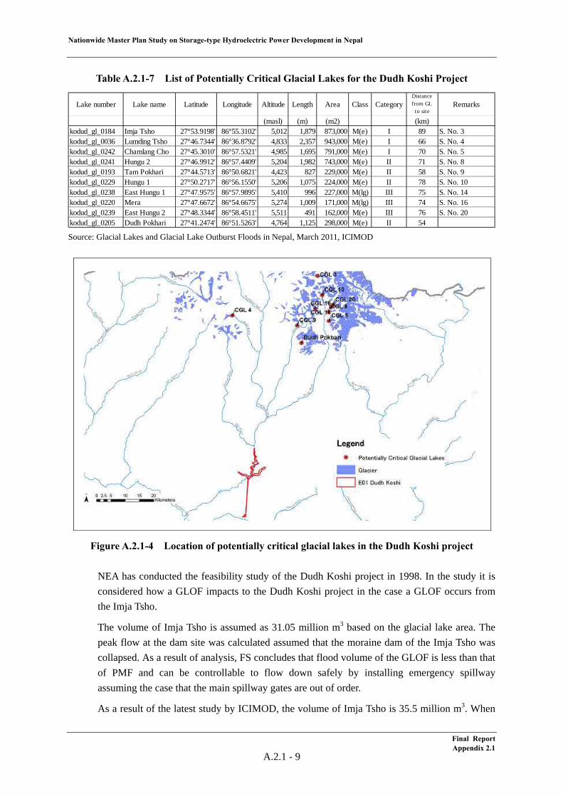
Although the Dudh Pokhari is listed in Table A.2.1-5 which is the list as of 2007, it is not included in Table A.2.1-6 which is one as of 2010. However, as the Dig Tsho is located near the Dudh Koshi project site, it should be included to review the risk of a GLOF of the Dudh Koshi project. Table A.2.1-6 shows the potentially critical glacial lakes of the Dudh Koshi project. Figure A.2.1-2 shows the location of them.
As shown in Table A.2.1-7, there are 10 potentially critical glacial lakes upstream of the Dudh Koshi project. Out of 10, 3 glacial lakes are classified in category I which means high risk for a GLOF. Therefore, the risk of a GLOF of the Dudh Koshi project is relatively high. The Imja Tsho is the most at risk for a GLOF.
Lake number Lake name Latitude Longitude Altitude Length Area Class Category(masl) (m) (m2)
kodud_gl_0184 Imja Tsho 27°53.9198' 86°55.3102' 5,012 1,879 873,000 M(e) Ikodud_gl_0036 Lumding Tsho 27°46.7344' 86°36.8792' 4,833 2,357 943,000 M(e) Ikodud_gl_0242 Chamlang Cho 27°45.3010' 86°57.5321' 4,985 1,695 791,000 M(e) Ikodud_gl_0241 Hungu 2 27°46.9912' 86°57.4409' 5,204 1,982 743,000 M(e) IIkodud_gl_0193 Tam Pokhari 27°44.5713' 86°50.6821' 4,423 827 229,000 M(e) IIkodud_gl_0229 Hungu 1 27°50.2717' 86°56.1550' 5,206 1,075 224,000 M(e) IIkodud_gl_0238 East Hungu 1 27°47.9575' 86°57.9895' 5,410 996 227,000 M(lg) IIIkodud_gl_0220 Mera 27°47.6672' 86°54.6675' 5,274 1,009 171,000 M(lg) IIIkodud_gl_0239 East Hungu 2 27°48.3344' 86°58.4511' 5,511 491 162,000 M(e) III
Final ReportAppendix 2.1
A.2.1 - 8
Nationwide Master Plan Study on Storage-type Hydroelectric Power Development in Nepal
Final Report Appendix 2.1
A.2.1 - 9
Table A.2.1-7 List of Potentially Critical Glacial Lakes for the Dudh Koshi Project
Source: Glacial Lakes and Glacial Lake Outburst Floods in Nepal, March 2011, ICIMOD
Figure A.2.1-4 Location of potentially critical glacial lakes in the Dudh Koshi project
NEA has conducted the feasibility study of the Dudh Koshi project in 1998. In the study it is considered how a GLOF impacts to the Dudh Koshi project in the case a GLOF occurs from the Imja Tsho.
The volume of Imja Tsho is assumed as 31.05 million m3 based on the glacial lake area. The peak flow at the dam site was calculated assumed that the moraine dam of the Imja Tsho was collapsed. As a result of analysis, FS concludes that flood volume of the GLOF is less than that of PMF and can be controllable to flow down safely by installing emergency spillway assuming the case that the main spillway gates are out of order.
As a result of the latest study by ICIMOD, the volume of Imja Tsho is 35.5 million m3. When
Lake number Lake name Latitude Longitude Altitude Length Area Class CategoryDistancefrom GL
to siteRemarks
(masl) (m) (m2) (km)kodud_gl_0184 Imja Tsho 27°53.9198' 86°55.3102' 5,012 1,879 873,000 M(e) I 89 S. No. 3kodud_gl_0036 Lumding Tsho 27°46.7344' 86°36.8792' 4,833 2,357 943,000 M(e) I 66 S. No. 4kodud_gl_0242 Chamlang Cho 27°45.3010' 86°57.5321' 4,985 1,695 791,000 M(e) I 70 S. No. 5kodud_gl_0241 Hungu 2 27°46.9912' 86°57.4409' 5,204 1,982 743,000 M(e) II 71 S. No. 8kodud_gl_0193 Tam Pokhari 27°44.5713' 86°50.6821' 4,423 827 229,000 M(e) II 58 S. No. 9kodud_gl_0229 Hungu 1 27°50.2717' 86°56.1550' 5,206 1,075 224,000 M(e) II 78 S. No. 10kodud_gl_0238 East Hungu 1 27°47.9575' 86°57.9895' 5,410 996 227,000 M(lg) III 75 S. No. 14kodud_gl_0220 Mera 27°47.6672' 86°54.6675' 5,274 1,009 171,000 M(lg) III 74 S. No. 16kodud_gl_0239 East Hungu 2 27°48.3344' 86°58.4511' 5,511 491 162,000 M(e) III 76 S. No. 20kodud_gl_0205 Dudh Pokhari 27°41.2474' 86°51.5263' 4,764 1,125 298,000 M(e) II 54
Nationwide Master Plan Study on Storage-type Hydroelectric Power Development in Nepal
the feasibility study for the Dudh Koshi project is conducted in future, the latest information should be considered to comprehend the impact of a GLOF on the Dudh Koshi project quantitatively.
4) Sediment Impact
According to the FS report, the specific sediment yield of the Dudh Koshi project site is estimated to be 2,540 t/km2/year. By using this yield, the life of the reservoir is estimated. The life of reservoir is an index to evaluate the sediment impact to reservoir and calculated dividing total storage volume by mean annual sediment yield.
Table A.2.1-8 shows the calculation result of the life of reservoir. The life of reservoir of the Dudh Koshi project is estimated to be 100 years.
However, a sand flushing facility such as adopted in the Tanahu project, which enables to flush out the sediment produced by a GLOF has to be studied, since several glacier lakes having potential risk of a GLOF exist at the upstream of Dudh Koshi project. The dam type that enables to install such sand flushing facilities in the dam has also to be studied.
Table A.2.1-8 Life of Reservoir
a) Specific Sediment Yield 2,540 t/km2/yr b) Sediment Yield
(Catchment Area × Specific Sediment Yield / Sediment Density)
6.9 × 10⁶ m3/yr (4,100 km2 × 2,540 t/km2/yr / 1.5 t/m3)
c) Total Storage Volume 687.4 × 10⁶ m3 d) Life time of Storage
(Total Storage Volume / Sediment Yield) 100 years
(687.4 × 10⁶ m3 / 6.9 × 10⁶ m3/yr)
(3) Geology
1) Site Geology
The Dudh Koshi project area belongs to the Okhaldhunga district and the Khotang district, east in Nepal. The dam site is located on the Dudh Koshi river. The powerhouse site is located on the left bank of the Sun Koshi river. According to the FS report (1998), the geology and engineering geology of the project area are summarized as follows.
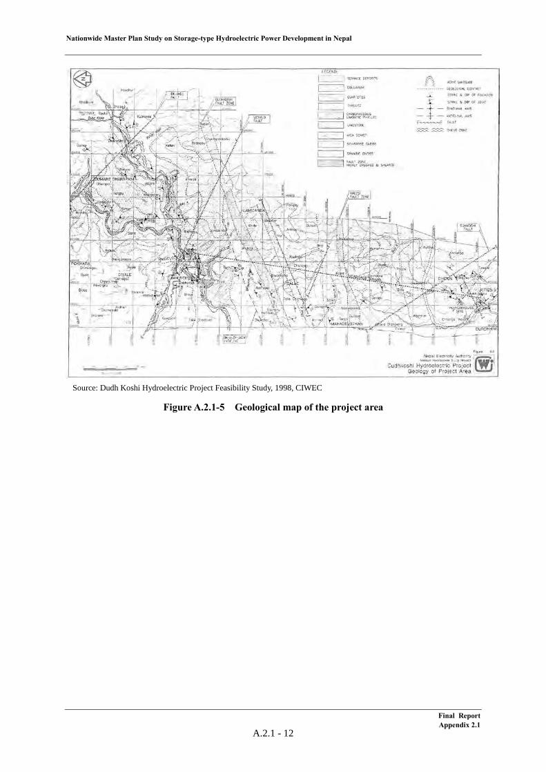
The project area lies in the Lesser Himalayan Zone, and is underlain by phyllite, quartzite, limestone, schist and gneiss. The geological map of the project area is shown in Figure A.2.1-3.
The reservoir and its surrounding area are underlain by phyllite and subordinate quartzite. Thotane fault, which is shown as Vichalo Faulr in Figure A.2.1-3, crosses the reservoir near the dam site. The reservoir area is watertight because of the lack of permeable rocks such as limestone. No major instability is observed in the reservoir area.
At the dam site, quartzite is distributed on the left bank, and phyllite on the right bank.
Final Report Appendix 2.1
A.2.1 - 10

Nationwide Master Plan Study on Storage-type Hydroelectric Power Development in Nepal
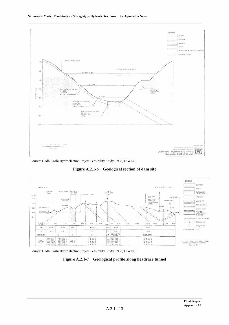
Bedding planes incline 10 to 30 degrees toward west or northwest, i.e. toward downstream or right bank. The geological section of the dam site is shown in Figure A.2.1-4. The rocks are permeable as indicated by many test sections of more than 10 Lu. Quartzite is more permeable than phyllite. The groundwater level of the left bank is slightly higher than river level. But, it is expected that permeability of bed rock decrease as the depth increase. The depth of river deposits was confirmed to be 19.2 m by a boring.
The headrace tunnel route passes the mountains between the Dudh Koshi river and the Sun Koshi river. The length of the tunnel is about 13 km. A geological section along the tunnel route is shown in Figure A.2.1-5. The route passes, from the intake to the surge tank, the section composed of phyllite and quartzite, the section of phyllite and limestone, and the section of schist and gneiss. This tunnel route encounters 3 major faults. The strike of bedding plane or foliation is NE-SW and at an angle of about 60 degrees to the tunnel direction. They incline toward intake in about 3 km long section from the intake to the Dudh Koshi Fault, and toward the surge tank in the remaining section. The overburden of this tunnel is up to 1,250 m.
The powerhouse is of underground type and its site is located on the left bank of the Baiku Khola river, a tributary on the left bank of the Sun Koshi river. This site is composed of schistose gneiss, which is strong. The RQD of this rock is 72%. Foliation of the gneiss inclines at angles of 20 to 50 degrees toward northwest.
For concrete aggregate, river sand and gravel distributed in the vicinity of the dam site are not suitable in terms of soundness, but quartzite distributed in the vicinity of the dam site is available. This quartzite is also available for rock materials. It has been confirmed that enough volume of soil materials are distributed in the vicinity of the dam site.
2) Site Geology
Among large tectonic thrust, MCT is located to the northwest of the dam site at a distance of 26 km. MBT is located to the southwest of the dam site at a distance of 26 km. The Thotane fault is a local major fault located to the west of the dam site at a distance of about 500 m.
3) Seismicity
The Project area is located in Lesser Himalaya. The horizontal ground acceleration of this area is 240 mgal according to the Seismic Hazard Map of Nepal. The nearest epicenter of M≧4 to the dam site is located to the northeast at a distance of about 10 km.
Final Report Appendix 2.1
A.2.1 - 11
Nationwide Master Plan Study on Storage-type Hydroelectric Power Development in Nepal
Source: Dudh Koshi Hydroelectric Project Feasibility Study, 1998, CIWEC
Figure A.2.1-5 Geological map of the project area
Final ReportAppendix 2.1
A.2.1 - 12
Nationwide Master Plan Study on Storage-type Hydroelectric Power Development in Nepal
Source: Dudh Koshi Hydroelectric Project Feasibility Study, 1998, CIWEC
Figure A.2.1-6 Geological section of dam site
Source: Dudh Koshi Hydroelectric Project Feasibility Study, 1998, CIWEC
Figure A.2.1-7 Geological profile along headrace tunnel
Final ReportAppendix 2.1
A.2.1 - 13
Nationwide Master Plan Study on Storage-type Hydroelectric Power Development in Nepal
(4) Development Plan
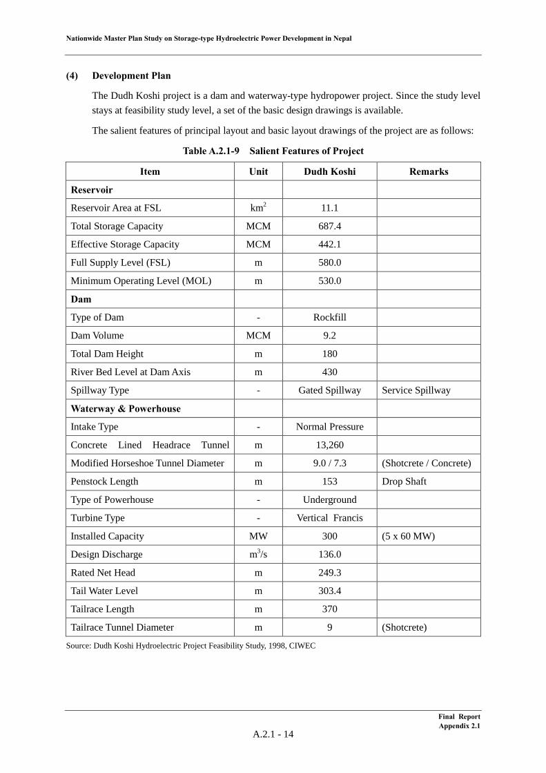
The Dudh Koshi project is a dam and waterway-type hydropower project. Since the study level stays at feasibility study level, a set of the basic design drawings is available.
The salient features of principal layout and basic layout drawings of the project are as follows:
Table A.2.1-9 Salient Features of Project
Item Unit Dudh Koshi Remarks
Reservoir
Reservoir Area at FSL km2 11.1
Total Storage Capacity MCM 687.4
Effective Storage Capacity MCM 442.1
Full Supply Level (FSL) m 580.0
Minimum Operating Level (MOL) m 530.0
Dam
Type of Dam - Rockfill
Dam Volume MCM 9.2
Total Dam Height m 180
River Bed Level at Dam Axis m 430
Spillway Type - Gated Spillway
Service Spillway Waterway & Powerhouse
Intake Type - Normal Pressure
Concrete Lined Headrace Tunnel
m 13,260
Modified Horseshoe Tunnel Diameter m 9.0 / 7.3 (Shotcrete / Concrete)
Penstock Length m 153 Drop Shaft
Type of Powerhouse - Underground
Turbine Type - Vertical Francis
Installed Capacity MW 300 (5 x 60 MW)
Design Discharge m3/s 136.0
Rated Net Head m 249.3
Tail Water Level m 303.4
Tailrace Length m 370
Tailrace Tunnel Diameter m 9 (Shotcrete)
Source: Dudh Koshi Hydroelectric Project Feasibility Study, 1998, CIWEC
Final Report Appendix 2.1
A.2.1 - 14
Nationw
ide Master Plan Study on Storage-type H
ydroelectric Power D
evelopment in N
epal
Source: Dudh K
oshi Hydroelectric Project Feasibility Study, 1998, C
IWEC
Figure A.2.1-8
General L
ayout
Final Report
Appendix 2.1
A.2.1 -15
Nationw
ide Master Plan Study on Storage-type H
ydroelectric Power D
evelopment in N
epal
Source: Dudh K
oshi Hydroelectric Project Feasibility Study, 1998, C
IWEC
FigureA.2.1-9
Dam
Plan
Final Report
Appendix 2.1
A.2.1 -16
Nationw
ide Master Plan Study on Storage-type H
ydroelectric Power D
evelopment in N
epal
Source: Dudh K
oshi Hydroelectric Project Feasibility Study, 1998, C
IWEC
Figure A.2.1-10
Dam
Section
Final Report
Appendix 2.1
A.2.1 -17
Nationw
ide Master Plan Study on Storage-type H
ydroelectric Power D
evelopment in N
epal
Source: Dudh K
oshi Hydroelectric Project Feasibility Study, 1998, C
IWEC
Figure A.2.1-11
Powerhouse
Plan
Final Report
Appendix 2.1
A.2.1 -18
Nationw
ide Master Plan Study on Storage-type H
ydroelectric Power D
evelopment in N
epal
Source: Dudh K
oshiHydroelectric Project Feasibility Study, 1998, C
IWEC
Figure A.2.1-12
Powerhouse Section
Final Report
Appendix 2.1
A.2.1 -19
Nationwide Master Plan Study on Storage-type Hydroelectric Power Development in Nepal
Further, the findings attained by the Study Team through site reconnaissance conducted in June, 2012 in terms of dam site and powerhouse site are summarized below.
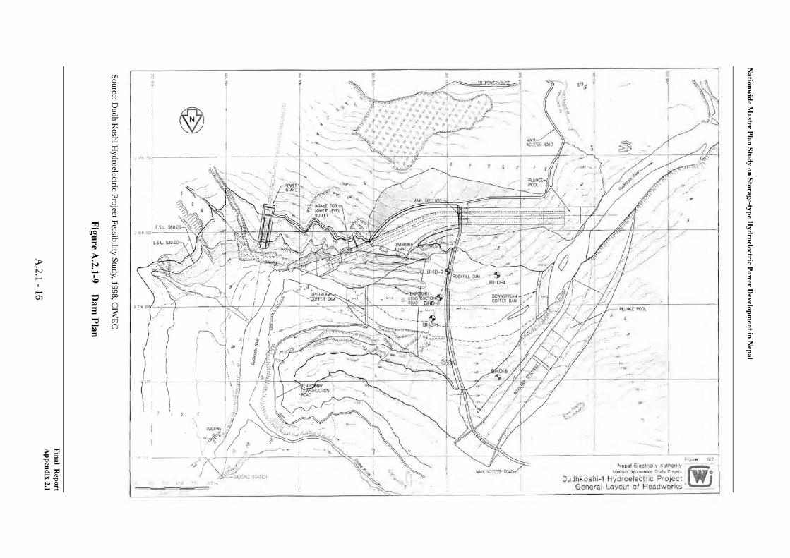
Dam Site
The dam site examined in the “Dudh Koshi Hydroelectric Project FS (1998)” conducted by CIWEC (Canadian International Water and Energy Consultants) is located at approximately 2 km downstream of the confluence of the Dudh Koshi river and the Rawa Khola river, where the curved river is flowing east-west direction. The coordinate at the dam axis is approximately 27º15’50”N, 86º39’09”E and river bed elevation is 430m.
The left bank abutment has uniform 40 degrees inclination. The thickness of the ridge at FSL is approximately 500m. The right bank abutment is a relatively thin ridge between the Dudh Koshi river and the Thotne Khola river which is joining immediately upstream of the dam site from the right bank side. The main stream and the tributary form U-shape edging the ridge, an emergency spillway is laid out on the ridge. The right bank abutment is laid out at the place where the thickness of the ridge is relatively small so that the excavation volume for the emergency spillway will be minimized. The distance between the tributary and main stream at FSL seems less than 200 m according to the drawings in the FS.
Powerhouse Site
According to the FS, a 150 m of head is gained by the dam, as the river bed elevation is 430 m and the FSL is 580 m. On the other hand, the tail water level is set at EL.303.35 considering FSL of Sapta Koshi dam (EL.304.8), Therefore, the rated gross head is 277.35 m. Namely, the gained head by conducting water to the powerhouse with 13.3 km headrace tunnel is 127.35 m.
While, in the “Master Plan Study on the Koshi River Water Resources Development (1985)” conducted by JICA, the tail water level is set at EL.424.6 m which is the FSL of the Sun Koshi No.1 project. A 2.6 km headrace tunnel conducts the water to the powerhouse without gaining head.
Therefore, a possible alternative for the present layout in the FS would be to lay out the powerhouse at immediately downstream of the dam at the left bank by changing the stream direction of the emergency spillway toward more downstream side. However, this layout was studied as an alternative adopting concrete dam and concluded to be less economical in the FS.
Although inflow into the Kurule dam which diverts river water from the Sun Koshi river to the Kamala river for irrigation and hydropower projects in the Sun Koshi Multipurpose Scheme (Phase I) would decrease since the Kurule dam is located at upstream of the outlet of the Dudh Koshi project, it is concluded that there would be no adverse effect because necessary water volume could be secured for the projects in the FS.
The location of powerhouse has to be determined by setting the tail water level considering the reservoir water levels of downstream projects. Regarding FSL of the Sapta Koshi dam, there seems different information. One is that the FSL was set at 304.8m in 1985 JICA study, the other is that the FSL was set at 335.25m in the FS conducted in India. Therefore, it should be confirmed that which water level has to be considered to determine the tail water level and location of powerhouse.
Final Report Appendix 2.1
A.2.1 - 20
Nationwide Master Plan Study on Storage-type Hydroelectric Power Development in Nepal
(5) Electrical/Mechanical Equipment and Transmission Line
1) General
Rated effective head, power discharge and installed capacity of the Dudh Koshi Project are as follows;
Rated Effective Head : 249.30 m Rated Power Discharge : 136 m3/s Installed Capacity : 300 MW
The HD Wiz (developed by J-POWER, based on existing hydropower plant data around world) has been used for reviewing design of electrical/mechanical equipment taking above information into consideration. Turbine efficiency and generator efficiency have been improved in recent years and installed capacity exceeded above-mentioned 300MW consequently.
2) Unit Capacity and Number of Unit
Generally, for the turbine-generator, a large unit capacity is said to be more economical merits of scale. However, optimum unit capacity of the turbine-generator is determined in consideration of influence to the power system, development timing and transportation restriction.
In this project, all electrical and mechanical equipment will be transporting from foreign countries via Indian national road and un-maintained Nepalese national road to the project site. Therefore maximum unit capacity shall be set as around 100 MW and number of 5 units plan has been adopted for the project.
3) Turbine
a) Turbine Output
Rated turbine output at rated effective head of 249.30m and rated power discharge of 27.20 m3/s per unit can be calculated as follow;
Pt = 9.8 × Hn × Qt × ηt = 9.8 × 249.3 × 27.20 × 0.922 ≈ 61,200 kW where Pt : Rated turbine output per unit (kW) Hn : Rated effective head (m) Qt : Rated power discharge per unit (m3/s) ηt : Turbine efficiency
b) Type of Turbine
Generally, type of turbine can be determined by close relation between effective head and turbine output. Vertical shaft Francis type turbine can be selected taking rated effective head and turbine output into consideration.
Final Report Appendix 2.1
A.2.1 - 21
Nationwide Master Plan Study on Storage-type Hydroelectric Power Development in Nepal
c) Runner Material
Stainless steel anti-corrosion type such as 13 chrome high nickels stainless steel is recommended to be applied for the runner material. Surface of runner and wear ring shall be coated (hard or soft) in case of water quality. Detailed coating method shall be specified in the detailed design stage.
d) Installed Capacity
Installed capacity can be calculated from aforementioned turbine output per unit as follow;
61,200 kW × 5 = 306,000 kW
Review of energy calculation is conducted by using above installed capacity.
4) Generator
A three phase alternating current synchronous generator with vertical shaft rated capacity of 66,400 kVA and power factor of 90% lag are selected.
a) Generator Capacity
Rated generator capacity can be calculated from rated turbine output, power factor and generator efficiency as follows;
Pg = Pt × ηg / p.f (kVA) = 61,200 × 0.970 / 0.90 ≈ 66,400 kVA where Pg : Rated generator capacity (kVA) Pt : Rated turbine output (kW) ηg : Generator efficiency p.f : Power factor, lag
As the results of above calculation, rated generator capacity is 66,400 kVA.
5) Transmission Line
Regarding designing of the transmission line, transmission line shall be connected to the closest substation based on 400 kV Transmission Line Power Development Plan by the NEA. And also thermal capacity and maximum surface potential gradient have been taken into consideration for designing of the transmission line and following specifications have been adopted. As for the transmission line length, the direct length from project area to closest substation was measured from map. Therefore, some allowance has been taken into consideration.
Connected Substation : Okhaldhunga Substation Transmission Line Voltage : 220 kV Length of Transmission Line : 43 km Conductor Type : Moose × 1, 2 circuits
Final Report Appendix 2.1
A.2.1 - 22

2.2 Kokhajor-1 Project (E-06)
Nationwide Master Plan Study on Storage-type Hydroelectric Power Development in Nepal
Table of Contents
(1) Project Summary ................................................................................................................... 1 (2) Meteorology & Hydrology .................................................................................................... 5 (3) Geology ................................................................................................................................. 6
(4) Development Plan ................................................................................................................. 9 (5) Electrical/Mechanical Equipment and Transmission Line .................................................... 11
List of Tables
Table A.2.2-1 Project Description ................................................................................................ 3 Table A.2.2-2 Monthly Rainfall at the Sindhuli Gadhi Station .................................................... 5 Table A.2.2-3 Monthly Rainfall at the Kabhrepalanchok Station ................................................ 5 Table A.2.2-4 Flow Data of the Kokhajor-1 Project ..................................................................... 6 Table A.2.2-5 Life of Reservoir .................................................................................................... 6 Table A.2.2-6 Salient Features...................................................................................................... 9
List of Figures
Figure A.2.2-1 Location of the Kokhajor-1 Project (E-06) .......................................................... 2 Figure A.2.2-2 General Layout of the Kokhajor-1 Project (E-06) ............................................... 2 Figure A.2.2-3 Land Use and Buildings in the Reservoir Area of the Kokhajor-1 Project .......... 4 Figure A.2.2-4 Geological map of the project area ...................................................................... 8 Figure A.2.2-5 Engineering geological map of the reservoir and its surrounding region ............ 8 Figure A.2.2-6 General Layout ..................................................................................................... 10
Final Report Appendix 2.2
Nationwide Master Plan Study on Storage-type Hydroelectric Power Development in Nepal
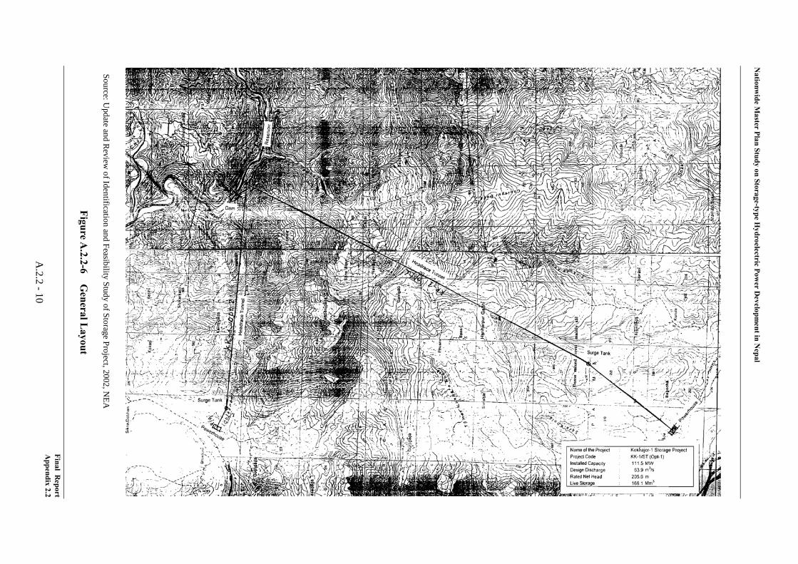
A.2.2 Kokhajor-1 (E-06)
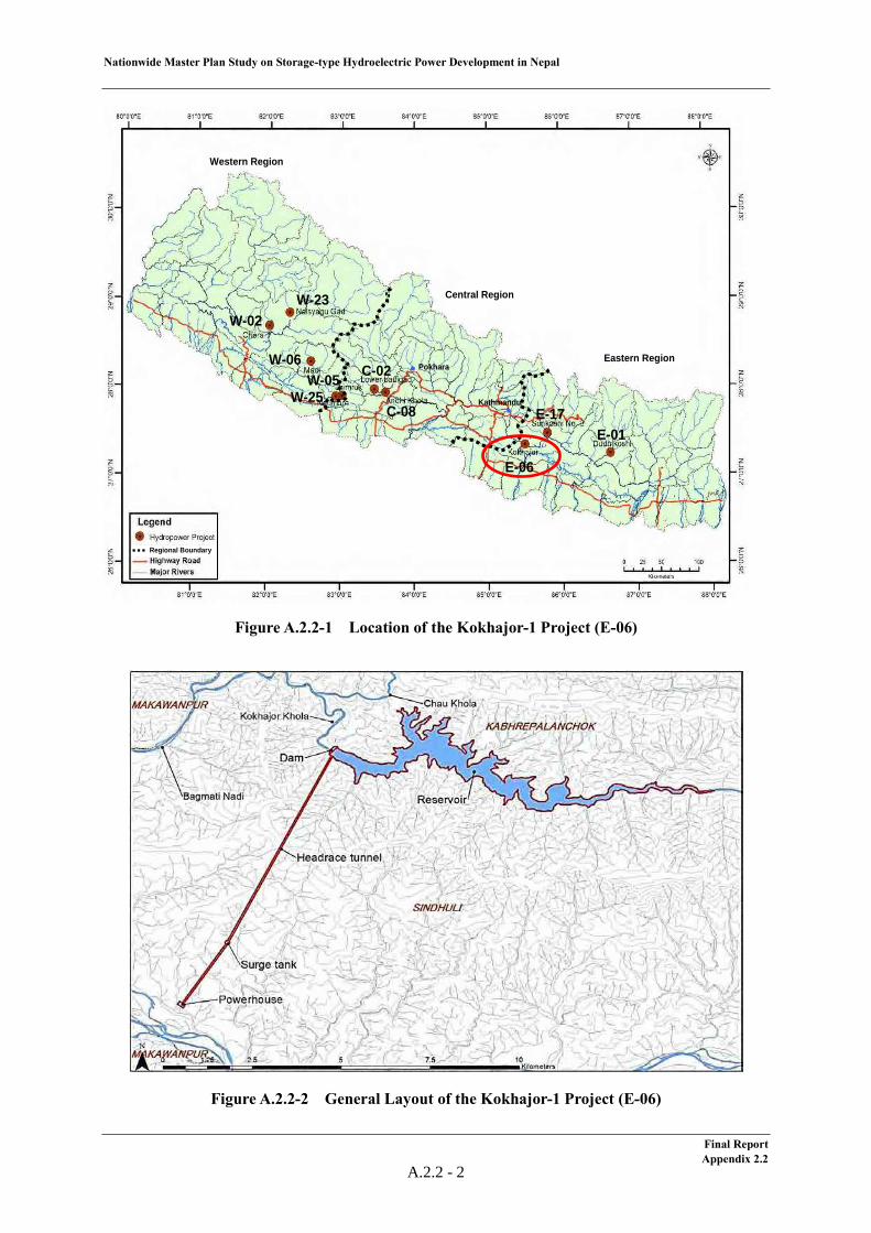
(1) Project Summary
The Kokhajor-1 Project is a 111.5 MW storage-type hydroelectric power project located in the Sinduli and Kabhrepalanchok Districts in the eastern region. The intake is located at the Kokhajor river and the outlet is located at the Bagmati river. The latest study for this project was conducted in the “Update and Review of Identification and Feasibility Study of Storage Project, 2002, NEA.” The study level for this project stays at the desk study level.
As hydrological characteristics, the annual rainfall at Panchkhal gauging station nearest to the project site is 1,209.5 mm and the average river discharge at the dam site is 17 m3/s. The drainage area is 281 km2, and the specific sediment volume is estimated to be 5,900 t/km2/year. This is larger than 3,300 t/km2/year, which is the value adopted by the NEA as average specific sedimentation volume in the eastern region. No glacier lake having a high risk of a GLOF is identified in the drainage basin.
From a geological view point, the project area lies in the Sub Himalaya Zone and is composed mainly of conglomerate, sandstone and mudstone. The reservoir area is underlain mainly by conglomerate and sandstone. The conglomerate, not well cemented and pervious, provides a corner where water tightness should be confirmed and has slopes which are easily eroded. The dam site is underlain by sandstone and mudstone which form a relatively soft and relatively pervious rock. The headrace tunnel route passes sandstone and mudstone, which form a medium hard to relatively soft rock. The portions close to a maximum overburden of about 600 m and need strong tunnel support. The bedrock of the powerhouse site is composed of sandstone and mudstone. The project area is located in an area where a large acceleration of 300 mgal is shown on the seismic hazard map. It is close to a large tectonic thrust (MBT) at a short distance of 2.5 km. It is away from epicenters larger than M4 at a long distance of 26 km.
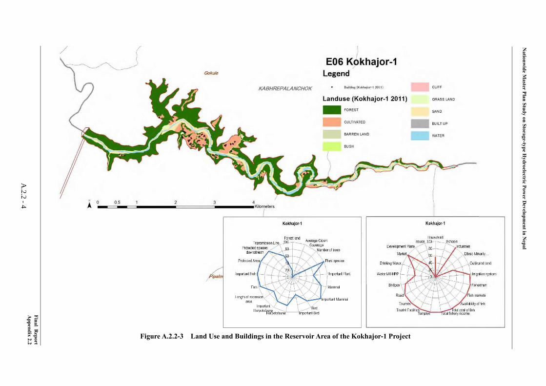
Impact on both the Natural Environment and the Social Environment is average. Kokhajor-1 is located in Bagmati river basin, and the reservoir area is 4.6 km2, which is the smallest next to Chera-1. The number of recorded fauna is relatively low, with numbers such as 13 mammals, 21 birds, and 8 Herpetofauna. The number of resettlements is 92, which are the lowest next to Dudh Koshi and the number of resettlement per unit generation is also low, at about 0.83 HH/MW. The affected Agricultural Land area is the lowest at 1.7 km2. There are only 2 affected irrigation schemes. One micro hydropower plant exists in the reservoir area. No fishermen were observed and neither drivable roads nor suspension bridges are affected. There used to be trouble related to construction of a cement plant. The Indigenous groups in the reservoir area are the Magar (Disadvantaged) and Tamang (Disadvantaged).
From the view point of hydropower planning, the proposed rockfill dam, which has a height of 107 m and volume of 4.7 million m3, is the smallest among the 10 promising projects. Therefore, the risk in construction of the dam seems relatively low. In terms of the waterway layout, the length of the headrace tunnel is 6.6 km and the penstock is 2 km. Since the length of the waterway is relatively long, the works for the headrace tunnel will be on the critical path in the construction stage.
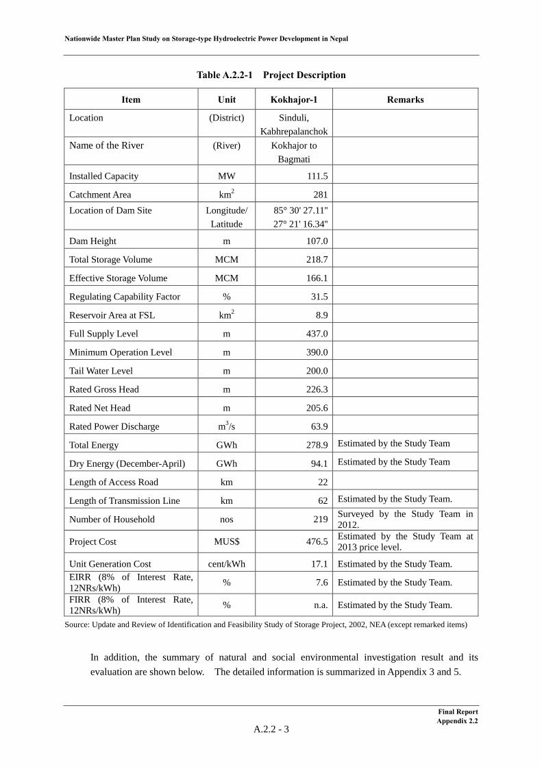
The location, basic layout and salient features of the project are shown below.
Final Report Appendix 2.2
A.2.2 - 1
Nationwide Master Plan Study on Storage-type Hydroelectric Power Development in Nepal
Figure A.2.2-1 Location of the Kokhajor-1 Project (E-06)
Figure A.2.2-2 General Layout of the Kokhajor-1 Project (E-06)
Western Region
Central Region
Eastern RegionPokhara
Kathmandu
Regional Boundary
W-23W-02
W-06
W-25W-05 C-02
C-08E-01
E-17
E-06
Western Region
Central Region
Eastern RegionPokhara
Kathmandu
Regional BoundaryRegional Boundary
W-23W-02
W-06
W-25W-05 C-02
C-08E-01
E-17
E-06
Final Report Appendix 2.2
A.2.2 - 2
Nationwide Master Plan Study on Storage-type Hydroelectric Power Development in Nepal
Table A.2.2-1 Project Description
Item Unit Kokhajor-1 Remarks
Location (District) Sinduli, Kabhrepalanchok
Name of the River (River) Kokhajor to Bagmati
Installed Capacity MW 111.5
Catchment Area km2 281 Location of Dam Site
Longitude/ Latitude
85° 30' 27.11'' 27° 21' 16.34''
Dam Height m 107.0
Total Storage Volume MCM 218.7
Effective Storage Volume MCM 166.1
Regulating Capability Factor % 31.5
Reservoir Area at FSL km2 8.9
Full Supply Level m 437.0
Minimum Operation Level m 390.0
Tail Water Level m 200.0
Rated Gross Head m 226.3
Rated Net Head m 205.6
Rated Power Discharge m3/s 63.9
Total Energy GWh 278.9 Estimated by the Study Team
Dry Energy (December-April) GWh 94.1 Estimated by the Study Team
Length of Access Road km 22
Length of Transmission Line km 62 Estimated by the Study Team.
Number of Household nos 219 Surveyed by the Study Team in 2012.
Project Cost MUS$ 476.5 Estimated by the Study Team at 2013 price level.
Unit Generation Cost cent/kWh 17.1 Estimated by the Study Team. EIRR (8% of Interest Rate, 12NRs/kWh) % 7.6 Estimated by the Study Team.
FIRR (8% of Interest Rate, 12NRs/kWh) % n.a. Estimated by the Study Team.
Source: Update and Review of Identification and Feasibility Study of Storage Project, 2002, NEA (except remarked items)
In addition, the summary of natural and social environmental investigation result and its evaluation are shown below. The detailed information is summarized in Appendix 3 and 5.
Final Report Appendix 2.2
A.2.2 - 3
Final Report
Appendix 2.2
A.2.2 -4
Nationw
ide Master Plan Study on Storage-type H
ydroelectric Power D
evelopment in N
epal
Figure A.2.2-3 Land Use and Buildings in the Reservoir Area of the Kokhajor-1 Project
Nationwide Master Plan Study on Storage-type Hydroelectric Power Development in Nepal
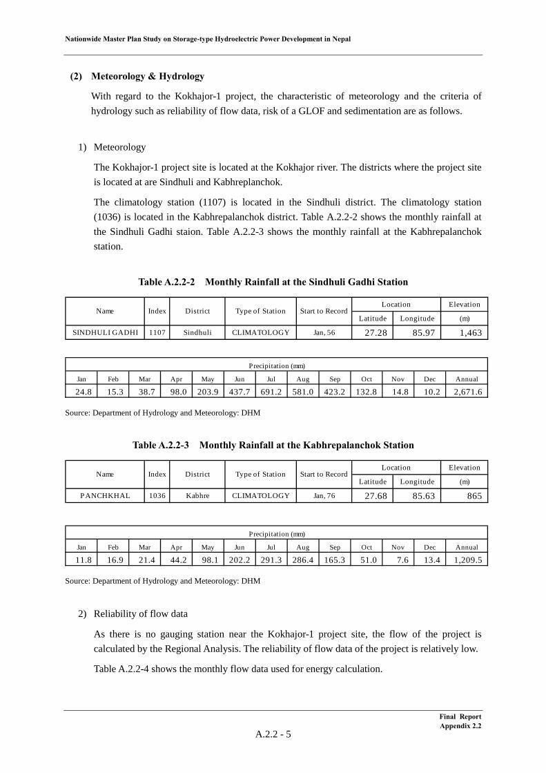
(2) Meteorology & Hydrology
With regard to the Kokhajor-1 project, the characteristic of meteorology and the criteria of hydrology such as reliability of flow data, risk of a GLOF and sedimentation are as follows.
1) Meteorology
The Kokhajor-1 project site is located at the Kokhajor river. The districts where the project site is located at are Sindhuli and Kabhreplanchok.
The climatology station (1107) is located in the Sindhuli district. The climatology station (1036) is located in the Kabhrepalanchok district. Table A.2.2-2 shows the monthly rainfall at the Sindhuli Gadhi staion. Table A.2.2-3 shows the monthly rainfall at the Kabhrepalanchok station.
Table A.2.2-2 Monthly Rainfall at the Sindhuli Gadhi Station
Source: Department of Hydrology and Meteorology: DHM
Table A.2.2-3 Monthly Rainfall at the Kabhrepalanchok Station
Source: Department of Hydrology and Meteorology: DHM
2) Reliability of flow data
As there is no gauging station near the Kokhajor-1 project site, the flow of the project is calculated by the Regional Analysis. The reliability of flow data of the project is relatively low.
Table A.2.2-4 shows the monthly flow data used for energy calculation.
Elevation
Latitude Longitude (m)
SINDHULI GADHI 1107 Sindhuli CLIMATOLOGY Jan, 56 27.28 85.97 1,463
Start to RecordName Index DistrictLocation
Type of Station
Jan Feb Mar Apr May Jun Jul Aug Sep Oct Nov Dec Annual
24.8 15.3 38.7 98.0 203.9 437.7 691.2 581.0 423.2 132.8 14.8 10.2 2,671.6
Precipitation (mm)
Elevation
Latitude Longitude (m)
PANCHKHAL 1036 Kabhre CLIMATOLOGY Jan, 76 27.68 85.63 865
Start to RecordName Index DistrictLocation
Type of Station
Jan Feb Mar Apr May Jun Jul Aug Sep Oct Nov Dec Annual
11.8 16.9 21.4 44.2 98.1 202.2 291.3 286.4 165.3 51.0 7.6 13.4 1,209.5
Precipitation (mm)
Final Report Appendix 2.2
A.2.2 - 5
Nationwide Master Plan Study on Storage-type Hydroelectric Power Development in Nepal
Table A.2.2-4 Flow Data of the Kokhajor-1 Project
3) Risk of GLOF
There is no potentially critical glacier lake which may cause a GLOF in the upstream area of the Kokhajor-1 project site.
4) Sedimentation
The specific sediment yield of the Kokhajor-1 project site was estimated to be 5,900 t/km2/year based on the sediment data at the gauging station (589) near the project site. By using this yield, the life of the reservoir is estimated. The life of reservoir is an index to evaluate the sediment impact to reservoir and calculated dividing total storage volume by mean annual sediment yield.
Table A.2.2-5 shows the calculation result of the life of reservoir. The life of reservoir of the Kokhajor-1 project is 199 years.
Table A.2.2-5 Life of Reservoir
a) Specific Sediment Yield 5,900 t/km2/yr b) Sediment Yield
(Catchment Area × Specific Sediment Yield / Sediment Density)
1.1 × 10⁶ m3/yr (281 km2 × 5,900 t/km2/yr / 1.5 t/m3)
c) Total Storage Volume 218.7 × 10⁶ m3 d) Life time of Storage
(Total Storage Volume / Sediment Yield) 199 years
(218.7 × 10⁶ m3 / 1.1 × 10⁶ m3/yr)
(3) Geology
1) Site Geology
The Kokhajor-1 project area belongs to the Sindhuli district, central in Nepal. The dam site is located in the valley of the Kokhajor river about 2 km upstream of the confluence of the Chau river. The powerhouse site is located on the left bank of the Baghmati river. According to the field geological survey, geology and engineering geology of the project area are as follows.
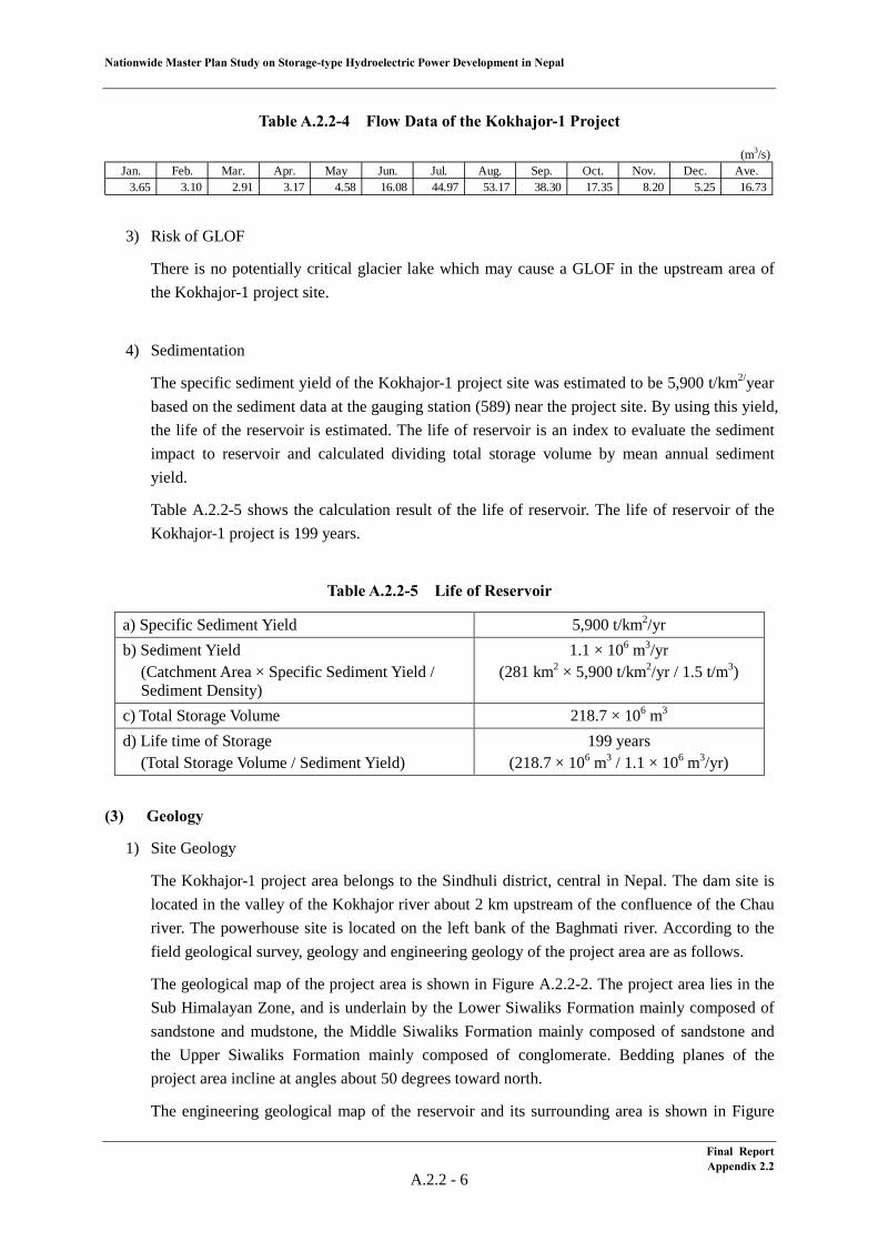
The geological map of the project area is shown in Figure A.2.2-2. The project area lies in the Sub Himalayan Zone, and is underlain by the Lower Siwaliks Formation mainly composed of sandstone and mudstone, the Middle Siwaliks Formation mainly composed of sandstone and the Upper Siwaliks Formation mainly composed of conglomerate. Bedding planes of the project area incline at angles about 50 degrees toward north.
The engineering geological map of the reservoir and its surrounding area is shown in Figure
(m3/s)Jan. Feb. Mar. Apr. May Jun. Jul. Aug. Sep. Oct. Nov. Dec. Ave.
3.65 3.10 2.91 3.17 4.58 16.08 44.97 53.17 38.30 17.35 8.20 5.25 16.73
Final Report Appendix 2.2
A.2.2 - 6
Nationwide Master Plan Study on Storage-type Hydroelectric Power Development in Nepal
A.2.2-3. Rock exposed area is widely distributed. Reservoir and its surrounding area are underlain by the Middle Siwaliks Formation and Upper Siwaliks Formation. Sandstone of the Middle Siwaliks Formation is medium hard. Conglomerate of the Upper Siwaliks Formation, however, is not well cemented and pervious. There is an area underlain by the Upper Siwaliks Formation on the right bank where the pass length of leakage is relatively short. The Upper Siwaliks Formation is eroded rather easily. Many shallow instabilities are observed in the area underlain by the Upper Siwaliks Formation.
The dam site is underlain by sandstone and mudstone of the Middle Siwaliks Formation, which is rather soft and rather pervious. Bedding planes of the dam site incline at angles of about 50 degrees toward north i.e. toward right bank. The depth of river deposits is assumed to be 10 to some 30 m.
The headrace tunnel route passes the ridge between the Kokhaj and Baghmati river. The reservoir side of the tunnel route passes the Middle Siwaliks Formation composed of medium hard sandstone. Remaining section of the tunnel route passes the Lower Siwaliks Formation composed of rather soft rocks. Bedding planes, which strike is about perpendicular to the tunnel direction, incline toward the intake at angles of about 50 degrees. The overburden of this tunnel is up to 600 m.
The powerhouse site is located on the alluvial terrace on the left bank of the Baghmati river. This site is composed of the Lower Siwaliks Formation. Bedding planes at this site incline toward the mountain. The depth of river deposits is assumed to be 10 to 20 m.
Sand and gravel for concrete aggregates are distributed on the riverbed of the Baghmati river about 10 km downstream of the dam site. Colluvium and residual soil distributed in the area underlain by mudstone would be investigated for borrow areas of soil materials. Sandstones in the vicinity of the dam site may available for rock materials.
2) Thrust and Fault
Among large tectonic thrust, MBT is located to the north of dam site at a distance of 2.5 km. A local major fault has not been found in the vicinity of the dam site.
3) Seismicity
The Project area is located in Sub Himalaya. The horizontal ground acceleration of this area is 300mgal according to the Seismic Hazard Map of Nepal. The nearest epicenter of M≧4 to the dam site is located to the NNE at a distance of about 26km.
Final Report Appendix 2.2
A.2.2 - 7
Nationwide Master Plan Study on Storage-type Hydroelectric Power Development in Nepal
Source: NESS Field Survey, 2012
Figure A.2.2-4 Geological map of the project area
Source: NESS Field Survey, 2012
Figure A.2.2-5 Engineering geological map of the reservoir and its surrounding region
Final ReportAppendix 2.2
A.2.2 - 8
Nationwide Master Plan Study on Storage-type Hydroelectric Power Development in Nepal
(4) Development Plan
Kokhajor-1 project is a dam and waterway-type hydropower project. Since the study level stays at desk study level, the basic design drawings are not available.
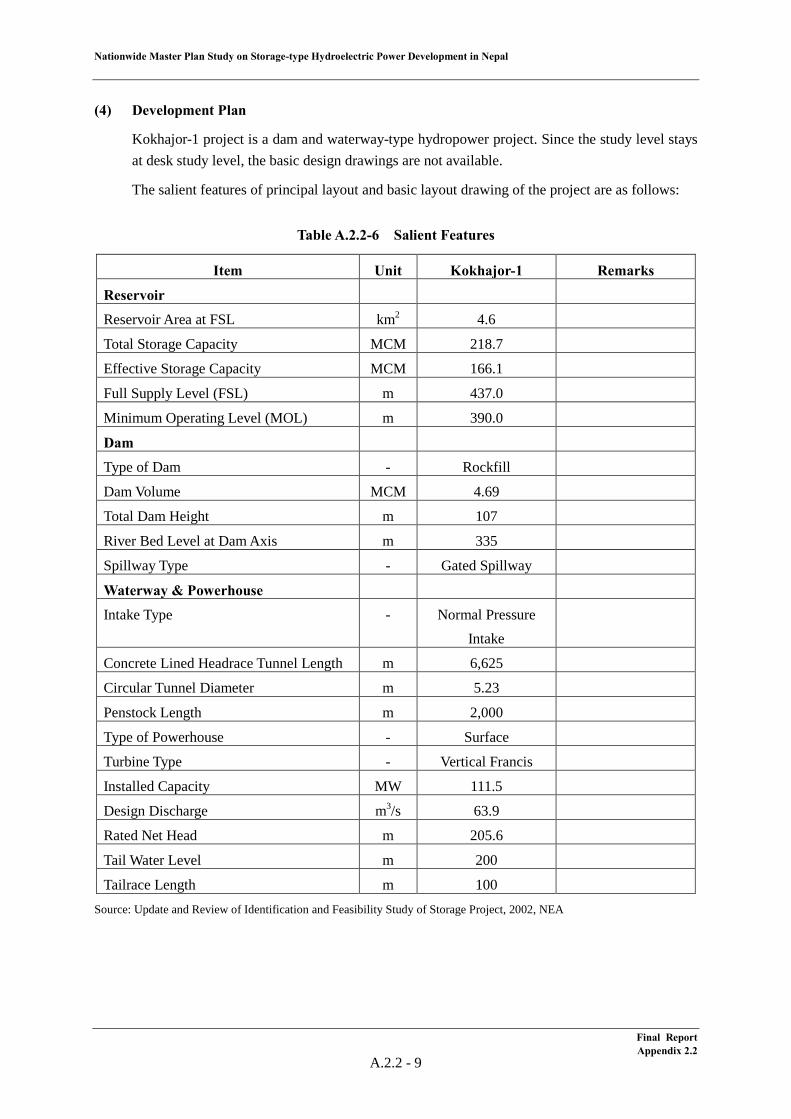
The salient features of principal layout and basic layout drawing of the project are as follows:
Table A.2.2-6 Salient Features
Item Unit Kokhajor-1 Remarks
Reservoir
Reservoir Area at FSL km2 4.6
Total Storage Capacity MCM 218.7
Effective Storage Capacity MCM 166.1
Full Supply Level (FSL) m 437.0
Minimum Operating Level (MOL) m 390.0
Dam
Type of Dam - Rockfill
Dam Volume MCM 4.69
Total Dam Height m 107
River Bed Level at Dam Axis m 335
Spillway Type - Gated Spillway
Waterway & Powerhouse
Intake Type - Normal Pressure Intake
Concrete Lined Headrace Tunnel Length m 6,625
Circular Tunnel Diameter m 5.23
Penstock Length m 2,000
Type of Powerhouse - Surface
Turbine Type - Vertical Francis
Installed Capacity MW 111.5
Design Discharge m3/s 63.9
Rated Net Head m 205.6
Tail Water Level m 200
Tailrace Length m 100 Source: Update and Review of Identification and Feasibility Study of Storage Project, 2002, NEA
Final Report Appendix 2.2
A.2.2 - 9
Nationw
ide Master Plan Study on Storage-type H
ydroelectric Power D
evelopment in N
epal
Source: Update and R
eview of Identification and Feasibility Study of Storage Project, 2002, N
EA
Figure A.2.2-6
General L
ayout
Final Report
Appendix 2.2
A.2.2
-10
Nationwide Master Plan Study on Storage-type Hydroelectric Power Development in Nepal
(5) Electrical/Mechanical Equipment and Transmission Line
1) General
Rated effective head, power discharge and installed capacity of the Kokhajor-1 Project are as follows;
Rated Effective Head : 205.60 m Rated Power Discharge : 63.90 m3/s Installed Capacity : 111.5 MW
The HD Wiz (developed by J-POWER, based on existing hydropower plant data around world) has been used for reviewing design of electrical/mechanical equipment taking above information into consideration. Turbine efficiency and generator efficiency have been improved in recent years and installed capacity exceeded above-mentioned 111.5 MW consequently.
2) Unit Capacity and Number of Unit
Generally, for the turbine-generator, a large unit capacity is said to be more economical merits of scale. However, optimum unit capacity of the turbine-generator is determined in consideration of influence to the power system, development timing and transportation restriction.
In this project, all electrical and mechanical equipment will be transporting from foreign countries via Indian national road and un-maintained Nepalese national road to the project site. Therefore maximum unit capacity shall be set as around 100 MW and number of 2 units plan has been adopted for the project taking accident, maintenance and operation into consideration.
3) Turbine
a) Turbine Output
Rated turbine output at rated effective head of 205.60m and rated power discharge of 31.35 m3/s per unit can be calculated as follow;
Pt = 9.8 × Hn × Qt × ηt = 9.8 × 205.60 × 31.95 × 0.926 =̇. 59,600 kW Where, Pg : Rated generator capacity (kVA) Hn : Rated effective head (m) Qt : Rated power discharge per unit (m3/s) ηt : Turbine efficiency
b) Type of Turbine
Generally, type of turbine can be determined by close relation between effective head and turbine output. Vertical shaft Francis type turbine can be selected taking rated effective head and turbine output into consideration.
Final Report Appendix 2.2
A.2.2 - 11
Nationwide Master Plan Study on Storage-type Hydroelectric Power Development in Nepal
c) Runner Material
Stainless steel anti-corrosion type such as 13 chrome high nickels stainless steel is recommended to be applied for the runner material. Surface of runner and wear ring shall be coated (hard or soft) in case of water quality. Detailed coating method shall be specified in the detailed design stage.
d) Installed Capacity
Installed capacity can be calculated from aforementioned turbine output per unit as follow;
59,600 kW × 2 = 119,200 kW
Review of energy calculation is conducted by using above installed capacity.
4) Generator
A three phase alternating current synchronous generator with vertical shaft rated capacity of 64,700 kVA and power factor of 90% lag are selected.
a) Generator Capacity
Rated generator capacity can be calculated from rated turbine output, power factor and generator efficiency as follows;
Pg = Pt × ηg / p.f (kVA) = 59,600 × 0.977 / 0.90 ≈ 64,700 kVA where Pg : Rated generator capacity (kVA) Pt : Rated turbine output (kW) ηg : Generator efficiency p.f : Power factor, lag
As the results of above calculation, rated generator capacity is 64,700 kVA.
5) Transmission Line
Regarding designing of the transmission line, transmission line shall be connected to the closest substation based on 400 kV Transmission Line Power Development Plan by the NEA. And also thermal capacity and maximum surface potential gradient have been taken into consideration for designing of the transmission line and following specifications have been adopted. As for the transmission line length, the direct length from project area to closest substation was measured from map. Therefore, some allowance has been taken into consideration.
Connected Substation : Hetauda Substation Transmission Line Voltage : 220 kV Length of Transmission Line : 62 km Conductor Type : Bison × 1, 2 circuits
Final Report Appendix 2.2
A.2.2 - 12

2.3 Sun Koshi No.3 Project (E-17)
Nationwide Master Plan Study on Storage-type Hydroelectric Power Development in Nepal
Table of Contents
(1) Project Summary ................................................................................................................... 1 (2) Meteorology & Hydrology .................................................................................................... 6 (3) Geology ................................................................................................................................. 9
(4) Development Plan ................................................................................................................. 13 (5) Electrical/Mechanical Equipment and Transmission Line .................................................... 16
List of Tables
Table A.2.3-1 Project Description ................................................................................................ 4 Table A.2.3-2 Monthly Rainfall at the Ramechhap Station .......................................................... 6 Table A.2.3-3 Flow Data for the Sun Koshi No.3 Project ............................................................ 6 Table A.2.3-4 Potentially Critical Glacial Lake in term of GLOF in the Sun Koshi Basin .......... 7 Table A.2.3-5 Life of Reservoir .................................................................................................... 8 Table A.2.3-6 Salient Features...................................................................................................... 13
List of Figures
Figure A.2.3-1 Location of the Sun Koshi No.3 Project (E-17) ................................................... 3 Figure A.2.3-2 General Layout of the Sun Koshi No.3 Project (E-17) ........................................ 3 Figure A.2.3-3 Land Use and Buildings in the Reservoir Area of the Sun Koshi No.3
Project ................................................................................................................... 5 Figure A.2.3-4 Potentially Critical Glacial Lakes for a GLOF for the Sun Koshi No.3
Project ................................................................................................................... 8 Figure A.2.3-5 Geological map of the project area ...................................................................... 10 Figure A.2.3-6 Engineering geological map of the reservoir and its surrounding region ............ 11 Figure A.2.3-7 Engineering geological map of the dam axis, waterway and powerhouse
area. ....................................................................................................................... 12 Figure A.2.3-8 General Layout ..................................................................................................... 14
Final Report Appendix 2.3
Nationwide Master Plan Study on Storage-type Hydroelectric Power Development in Nepal
A.2.3 Sun Koshi No.3 (E-17)
(1) Project Summary
The Sun Koshi No.3 Project is a 536 MW storage-type hydroelectric power project located at the Sun Koshi river in the Ramechhap, Kabhrepalanchok and Sindhupalchok Districts in the eastern region. This project was originally discovered in the “Master Plan Study on the Koshi River Water Resource Development, 1985” carried out by JICA. The study level for this project stays at the desk study level.
Further, the JICA Study Team conducted a site reconnaissance at Sun Koshi No.3 project site in June 2012. The findings attained through site reconnaissance are also summarized in this clause.
As hydrological characteristics, the annual rainfall at Manthali gauging station nearest to the project site is 994 mm, however, the average river discharge at the dam site is significant, 220 m3/s. The catchment area is 5,520 km2, and the specific sediment volume is estimated to be 1,871 t/km2/year. This is smaller than 3,300 t/km2/year, which is the value adopted by the NEA as average specific sedimentation volume in the eastern region. It has to be noted that two glacier lakes having a high risk of a GLOF are identified in the drainage basin.
From a geological view point, the project area lies in the Lesser Himalaya Zone and is composed mainly of quartzite, slate and phyllite. The reservoir area is underlain mainly by quartzite and slate. This area is water tight, but slopes in its surrounding area are widely covered with colluvium, which would provide many unstable slopes. The dam site is underlain by quartzite, which is intercalated by phyllite and forms hard and impervious rock. The headrace tunnel route passes through quartzite which is intercalated by phyllite, and forms hard and compact rock. The bedrock of the powerhouse site is composed of quartzite and phyllite. The project area is located in the area where a medium acceleration of 190 mgal is shown on the seismic hazard map. It is away from a large tectonic thrust (MBT) at a long distance of 16 km and from epicenters larger than M4 at a long distance of 28 km.
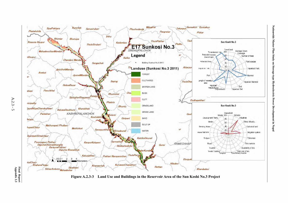
The impact on the Natural Environment is average and the impact on the Social Environment is high. Sun Koshi No.3 is located in the Koshi river basin and the reservoir area is 30.1 km2, which is the largest in the 10 promising projects. The impact on forest is also the largest, which is 8.15 km2. The number of recorded fishes is 21, which are relatively high. The dewatering area is the smallest at 0.5 km. The length of the Transmission Line is relatively shorter and is about 35 km. The number of resettlements is 1,599, which is the largest next to Lower Badigad. The affected Agricultural land is also the largest at 9.4 km2. The number of affected fishermen will be 712 and the affected fish markets will be 7, which is the highest out of the 10 promising projects. Around 20,000 tourists are visiting the project site every year, which is the biggest impact on tourism. 15km of paved roads, 24.4 km of drivable roads, 13 suspension bridges, and 22 water supply schemes will be affected. Two irrigation projects, one ring road, one bridge, one water pump, and four road expansion projects are planned in the reservoir area. There used to be trouble related to the road expansion plan. The Indigenous groups in the reservoir area are the Newar (Advanced), Magar (Disadvantaged), Tamang (Disadvantaged), Majhi (Marginalised) and Tharu (Marginalised).
Final Report Appendix 2.2
A.2.3 - 1
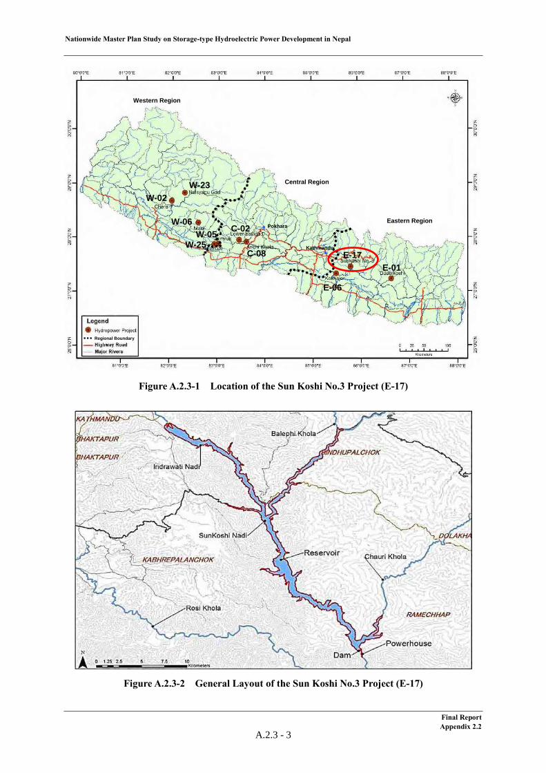
Nationwide Master Plan Study on Storage-type Hydroelectric Power Development in Nepal
From the view point of hydropower planning, the proposed concrete dam with a height of 140 m makes a large effective reservoir volume of 555 million m3. The large rated power discharge of 570 m3/s is required to gain 536 MW of installed capacity due to the small effective head of 109 m. Therefore, a large size of electromechanical equipment is also required, which makes the construction cost relatively high. The setting of a full supply level of the reservoir has to be reviewed since 6 km of the Araniko Highway which will connect Nepal and China is to be submerged in the reservoir, having a length of 30 km in the current layout. Furthermore, a spillway which can control a GLOF and a sand flushing facility which enables flushing out sedimentation produced by a GLOF has to be planned.
The location, basic layout and salient features of the project are shown below.
Final Report Appendix 2.2
A.2.3 - 2
Nationwide Master Plan Study on Storage-type Hydroelectric Power Development in Nepal
Figure A.2.3-1 Location of the Sun Koshi No.3 Project (E-17)
Figure A.2.3-2 General Layout of the Sun Koshi No.3 Project (E-17)
Western Region
Central Region
Eastern RegionPokhara
Kathmandu
Regional Boundary
W-23W-02
W-06
W-25W-05 C-02
C-08E-01
E-17
E-06
Western Region
Central Region
Eastern RegionPokhara
Kathmandu
Regional BoundaryRegional Boundary
W-23W-02
W-06
W-25W-05 C-02
C-08E-01
E-17
E-06
Final Report Appendix 2.2
A.2.3 - 3
Nationwide Master Plan Study on Storage-type Hydroelectric Power Development in Nepal
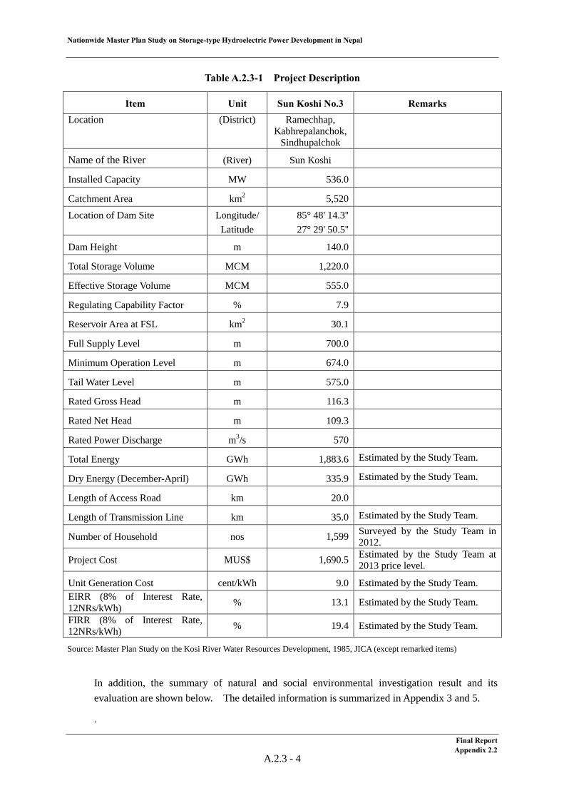
Table A.2.3-1 Project Description
Item Unit Sun Koshi No.3 Remarks Location (District) Ramechhap,
Kabhrepalanchok, Sindhupalchok
Name of the River (River) Sun Koshi
Installed Capacity MW 536.0
Catchment Area km2 5,520
Location of Dam Site
Longitude/ Latitude
85° 48' 14.3'' 27° 29' 50.5''
Dam Height m 140.0
Total Storage Volume MCM 1,220.0
Effective Storage Volume MCM 555.0
Regulating Capability Factor % 7.9
Reservoir Area at FSL km2 30.1
Full Supply Level m 700.0
Minimum Operation Level m 674.0
Tail Water Level m 575.0
Rated Gross Head m 116.3
Rated Net Head m 109.3
Rated Power Discharge m3/s 570
Total Energy GWh 1,883.6 Estimated by the Study Team.
Dry Energy (December-April) GWh 335.9 Estimated by the Study Team.
Length of Access Road km 20.0
Length of Transmission Line km 35.0 Estimated by the Study Team.
Number of Household nos 1,599 Surveyed by the Study Team in 2012.
Project Cost MUS$ 1,690.5 Estimated by the Study Team at 2013 price level.
Unit Generation Cost cent/kWh 9.0 Estimated by the Study Team. EIRR (8% of Interest Rate, 12NRs/kWh) % 13.1 Estimated by the Study Team.
FIRR (8% of Interest Rate, 12NRs/kWh) % 19.4 Estimated by the Study Team.
Source: Master Plan Study on the Kosi River Water Resources Development, 1985, JICA (except remarked items)
In addition, the summary of natural and social environmental investigation result and its evaluation are shown below. The detailed information is summarized in Appendix 3 and 5.
.
Final Report Appendix 2.2
A.2.3 - 4
Nationw
ide Master Plan Study on Storage-type H
ydroelectric Power D
evelopment in N
epal
Final Report
Appendix 2.3
A.2.3 -5
Figure A.2.3-3 Land Use and Buildings in the Reservoir Area of the Sun Koshi No.3 Project
Nationwide Master Plan Study on Storage-type Hydroelectric Power Development in Nepal
(2) Meteorology & Hydrology
With regard to the Sun Koshi No.3 project, the meteorological characteristics and the criteria for hydrological evaluation, namely reliability of flow data, risk of a GLOF and sediment impact are mentioned below.
1) Meteorology
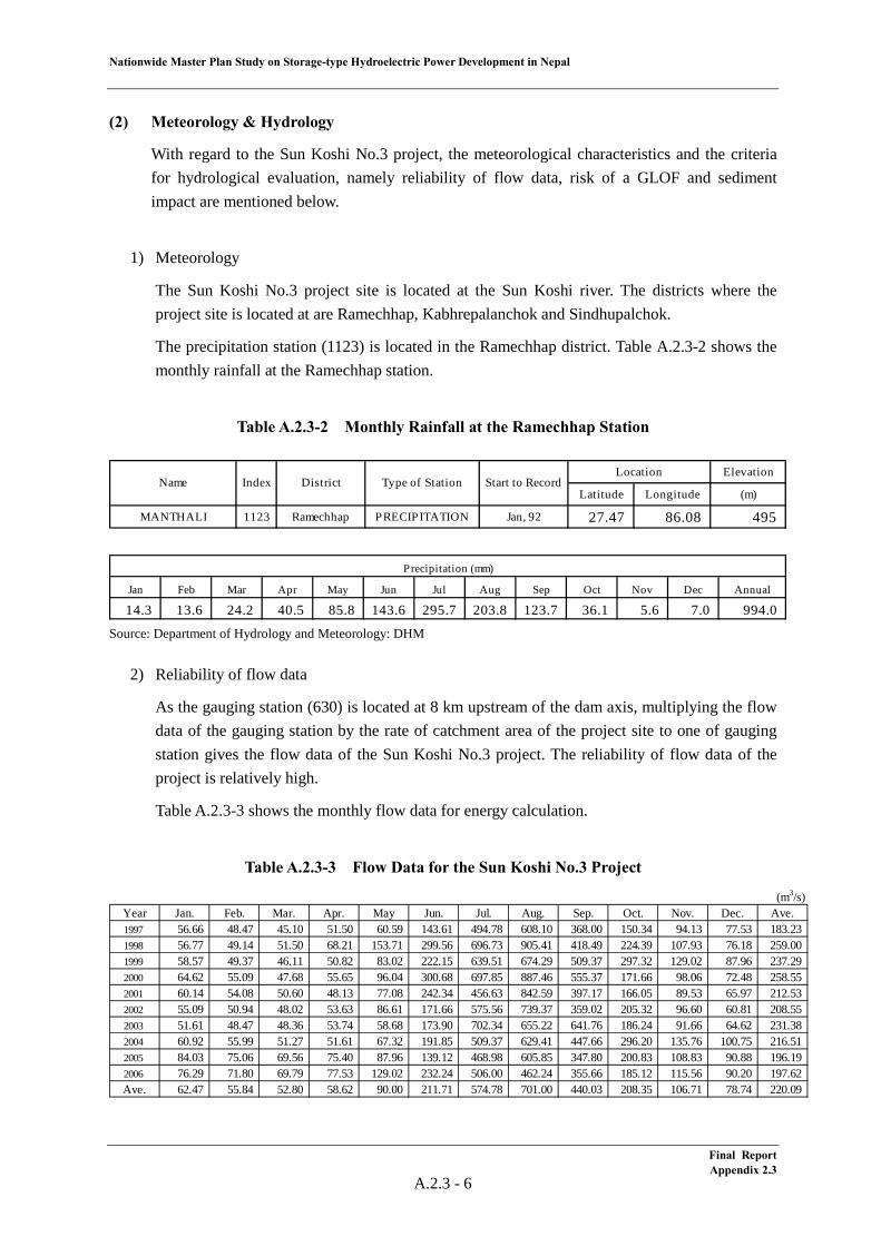
The Sun Koshi No.3 project site is located at the Sun Koshi river. The districts where the project site is located at are Ramechhap, Kabhrepalanchok and Sindhupalchok.
The precipitation station (1123) is located in the Ramechhap district. Table A.2.3-2 shows the monthly rainfall at the Ramechhap station.
Table A.2.3-2 Monthly Rainfall at the Ramechhap Station
Source: Department of Hydrology and Meteorology: DHM
2) Reliability of flow data
As the gauging station (630) is located at 8 km upstream of the dam axis, multiplying the flow data of the gauging station by the rate of catchment area of the project site to one of gauging station gives the flow data of the Sun Koshi No.3 project. The reliability of flow data of the project is relatively high.
Table A.2.3-3 shows the monthly flow data for energy calculation.
Table A.2.3-3 Flow Data for the Sun Koshi No.3 Project
Elevation
Latitude Longitude (m)
MANTHALI 1123 Ramechhap PRECIPITATION Jan, 92 27.47 86.08 495
Start to RecordName Index DistrictLocation
Type of Station
Jan Feb Mar Apr May Jun Jul Aug Sep Oct Nov Dec Annual
14.3 13.6 24.2 40.5 85.8 143.6 295.7 203.8 123.7 36.1 5.6 7.0 994.0
Precipitation (mm)
(m3/s)Year Jan. Feb. Mar. Apr. May Jun. Jul. Aug. Sep. Oct. Nov. Dec. Ave.1997 56.66 48.47 45.10 51.50 60.59 143.61 494.78 608.10 368.00 150.34 94.13 77.53 183.231998 56.77 49.14 51.50 68.21 153.71 299.56 696.73 905.41 418.49 224.39 107.93 76.18 259.001999 58.57 49.37 46.11 50.82 83.02 222.15 639.51 674.29 509.37 297.32 129.02 87.96 237.292000 64.62 55.09 47.68 55.65 96.04 300.68 697.85 887.46 555.37 171.66 98.06 72.48 258.552001 60.14 54.08 50.60 48.13 77.08 242.34 456.63 842.59 397.17 166.05 89.53 65.97 212.532002 55.09 50.94 48.02 53.63 86.61 171.66 575.56 739.37 359.02 205.32 96.60 60.81 208.552003 51.61 48.47 48.36 53.74 58.68 173.90 702.34 655.22 641.76 186.24 91.66 64.62 231.382004 60.92 55.99 51.27 51.61 67.32 191.85 509.37 629.41 447.66 296.20 135.76 100.75 216.512005 84.03 75.06 69.56 75.40 87.96 139.12 468.98 605.85 347.80 200.83 108.83 90.88 196.192006 76.29 71.80 69.79 77.53 129.02 232.24 506.00 462.24 355.66 185.12 115.56 90.20 197.62Ave. 62.47 55.84 52.80 58.62 90.00 211.71 574.78 701.00 440.03 208.35 106.71 78.74 220.09
Final Report Appendix 2.3
A.2.3 - 6
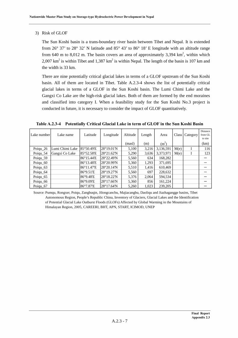
Nationwide Master Plan Study on Storage-type Hydroelectric Power Development in Nepal
3) Risk of GLOF
The Sun Koshi basin is a trans-boundary river basin between Tibet and Nepal. It is extended from 26° 37’ to 28° 32’ N latitude and 85° 43’ to 86° 18’ E longitude with an altitude range from 640 m to 8,012 m. The basin covers an area of approximately 3,394 km2, within which 2,007 km2 is within Tibet and 1,387 km2 is within Nepal. The length of the basin is 107 km and the width is 33 km.
There are nine potentially critical glacial lakes in terms of a GLOF upstream of the Sun Koshi basin. All of them are located in Tibet. Table A.2.3-4 shows the list of potentially critical glacial lakes in terms of a GLOF in the Sun Koshi basin. The Lumi Chimi Lake and the Gangxi Co Lake are the high-risk glacial lakes. Both of them are formed by the end moraines and classified into category I. When a feasibility study for the Sun Koshi No.3 project is conducted in future, it is necessary to consider the impact of GLOF quantitatively.
Table A.2.3-4 Potentially Critical Glacial Lake in term of GLOF in the Sun Koshi Basin
Source: Pumqu, Rongxer, Poiqu, Zangbuqin, Jilongcancbu, Majiacangbu, Daoliqu and Jiazhagangge basins, Tibet
Autonomous Region, People’s Republic China, Inventory of Glaciers, Glacial Lakes and the Identification of Potential Glacial Lake Outburst Floods (GLOFs) Affected by Global Warming in the Mountains of Himalayan Region, 2005, CAREERI, BHT, APN, START, ICIMOD, UNEP
Lake number Lake name Latitude Longitude Altitude Length Area Class CategoryDistancefrom GL
to site
(masl) (m) (m2) (km)Poiqu_26 Lumi Chimi Lake 85°50.49'E 28°19.01'N 5,100 3,216 3,136,591 M(e) I 116Poiqu_54 Gangxi Co Lake 85°52.58'E 28°21.62'N 5,290 3,636 3,373,971 M(e) I 123Poiqu_59 86°15.44'E 28°22.49'N 5,560 634 168,282 -Poiqu_60 86°13.48'E 28°20.99'N 5,360 1,293 371,695 -Poiqu_63 86°11.47'E 28°20.14'N 5,510 1,416 610,469 -Poiqu_64 86°9.51'E 28°19.27'N 5,560 697 228,632 -Poiqu_65 86°9.48'E 28°18.22'N 5,376 2,064 594,534 -Poiqu_66 86°9.09'E 28°17.66'N 5,360 856 161,224 -Poiqu_67 86°7.87'E 28°17.64'N 5,260 1,023 239,205 -
Final Report Appendix 2.3
A.2.3 - 7
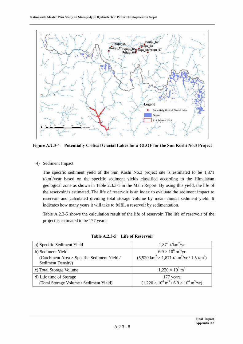
Nationwide Master Plan Study on Storage-type Hydroelectric Power Development in Nepal
Figure A.2.3-4 Potentially Critical Glacial Lakes for a GLOF for the Sun Koshi No.3 Project
4) Sediment Impact
The specific sediment yield of the Sun Koshi No.3 project site is estimated to be 1,871 t/km2/year based on the specific sediment yields classified according to the Himalayan geological zone as shown in Table 2.3.3-1 in the Main Report. By using this yield, the life of the reservoir is estimated. The life of reservoir is an index to evaluate the sediment impact to reservoir and calculated dividing total storage volume by mean annual sediment yield. It indicates how many years it will take to fulfill a reservoir by sedimentation.
Table A.2.3-5 shows the calculation result of the life of reservoir. The life of reservoir of the project is estimated to be 177 years.
Table A.2.3-5 Life of Reservoir
a) Specific Sediment Yield 1,871 t/km2/yr b) Sediment Yield
(Catchment Area × Specific Sediment Yield / Sediment Density)
6.9 × 10⁶ m3/yr (5,520 km2 × 1,871 t/km2/yr / 1.5 t/m3)
c) Total Storage Volume 1,220 × 106 m3 d) Life time of Storage (Total Storage Volume / Sediment Yield)
177 years (1,220 × 106 m3 / 6.9 × 10⁶ m3/yr)
Final Report Appendix 2.3
A.2.3 - 8
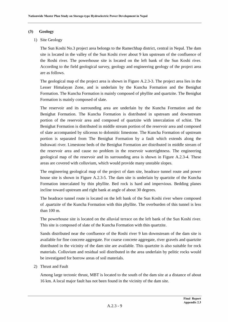
Nationwide Master Plan Study on Storage-type Hydroelectric Power Development in Nepal
(3) Geology
1) Site Geology
The Sun Koshi No.3 project area belongs to the Ramechhap district, central in Nepal. The dam site is located in the valley of the Sun Koshi river about 9 km upstream of the confluence of the Roshi river. The powerhouse site is located on the left bank of the Sun Koshi river. According to the field geological survey, geology and engineering geology of the project area are as follows.
The geological map of the project area is shown in Figure A.2.3-3. The project area lies in the Lesser Himalayan Zone, and is underlain by the Kuncha Formation and the Benighat Formation. The Kuncha Formation is mainly composed of phyllite and quartzite. The Benighat Formation is mainly composed of slate.
The reservoir and its surrounding area are underlain by the Kuncha Formation and the Benighat Formation. The Kuncha Formation is distributed in upstream and downstream portion of the reservoir area and composed of quartzite with intercalation of schist. The Benighat Formation is distributed in middle stream portion of the reservoir area and composed of slate accompanied by siliceous to dolomitic limestone. The Kuncha Formation of upstream portion is separated from The Benighat Formation by a fault which extends along the Indrawati river. Limestone beds of the Benighat Formation are distributed in middle stream of the reservoir area and cause no problem in the reservoir watertightness. The engineering geological map of the reservoir and its surrounding area is shown in Figure A.2.3-4. These areas are covered with colluvium, which would provide many unstable slopes.
The engineering geological map of the project of dam site, headrace tunnel route and power house site is shown in Figure A.2.3-5. The dam site is underlain by quartzite of the Kuncha Formation intercalated by thin phyllite. Bed rock is hard and impervious. Bedding planes incline toward upstream and right bank at angle of about 30 degrees.
The headrace tunnel route is located on the left bank of the Sun Koshi river where composed of .quartzite of the Kuncha Formation with thin phyllite. The overburden of this tunnel is less than 100 m.
The powerhouse site is located on the alluvial terrace on the left bank of the Sun Koshi river. This site is composed of slate of the Kuncha Formation with thin quartzite.
Sands distributed near the confluence of the Roshi river 9 km downstream of the dam site is available for fine concrete aggregate. For coarse concrete aggregate, river gravels and quartzite distributed in the vicinity of the dam site are available. This quartzite is also suitable for rock materials. Colluvium and residual soil distributed in the area underlain by pelitic rocks would be investigated for borrow areas of soil materials.
2) Thrust and Fault
Among large tectonic thrust, MBT is located to the south of the dam site at a distance of about 16 km. A local major fault has not been found in the vicinity of the dam site.
Final Report Appendix 2.3
A.2.3 - 9
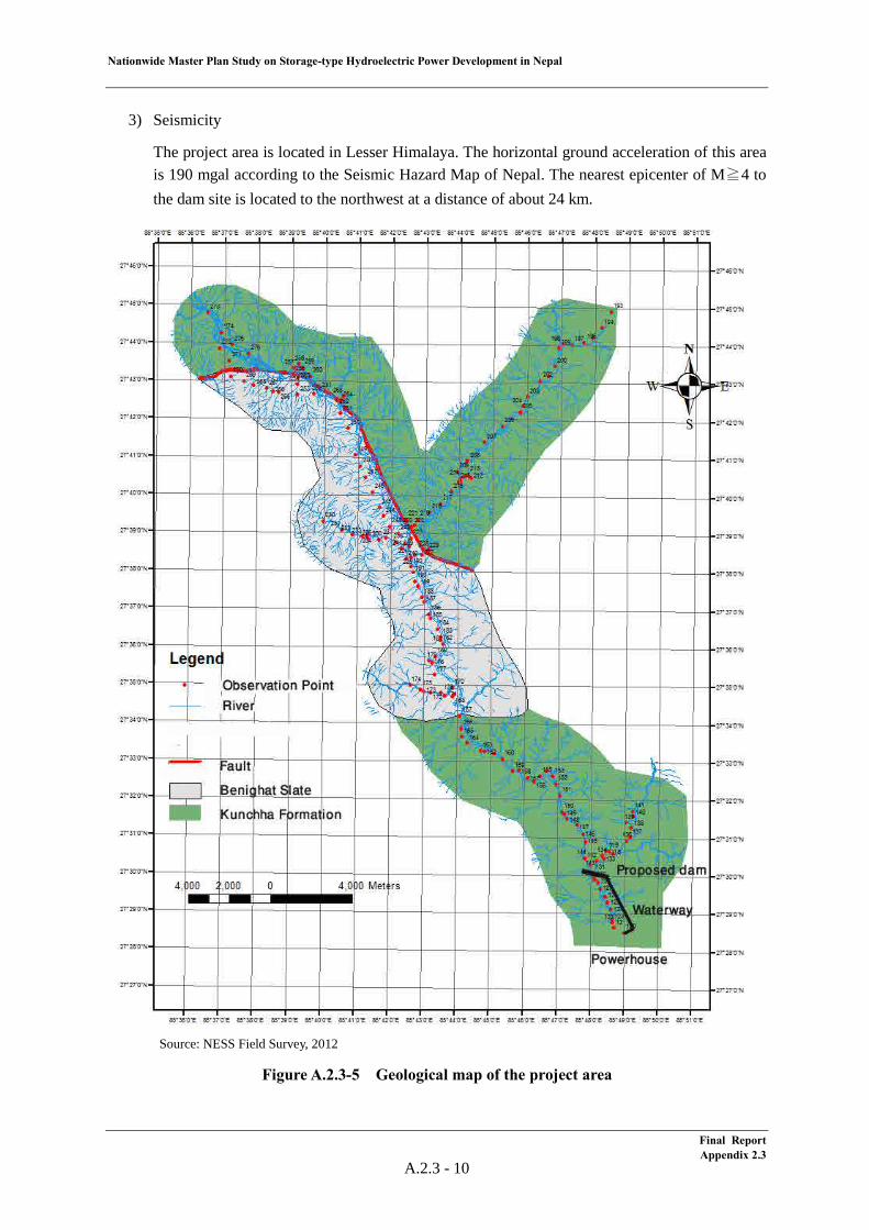
Nationwide Master Plan Study on Storage-type Hydroelectric Power Development in Nepal
3) Seismicity
The project area is located in Lesser Himalaya. The horizontal ground acceleration of this area is 190 mgal according to the Seismic Hazard Map of Nepal. The nearest epicenter of M≧4 to the dam site is located to the northwest at a distance of about 24 km.
Source: NESS Field Survey, 2012
Figure A.2.3-5 Geological map of the project area
Final Report Appendix 2.3
A.2.3 - 10
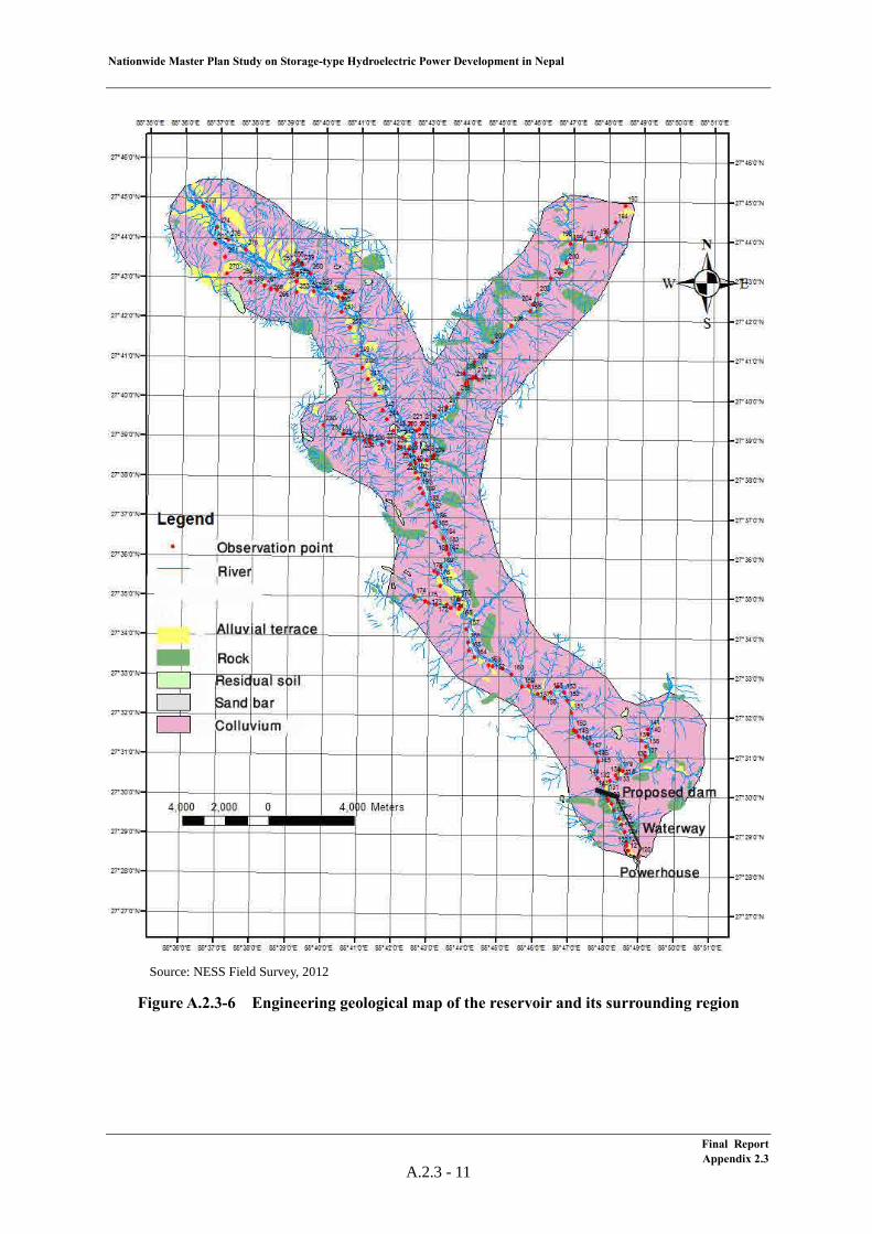
Nationwide Master Plan Study on Storage-type Hydroelectric Power Development in Nepal
Source: NESS Field Survey, 2012
Figure A.2.3-6 Engineering geological map of the reservoir and its surrounding region
Final Report Appendix 2.3
A.2.3 - 11
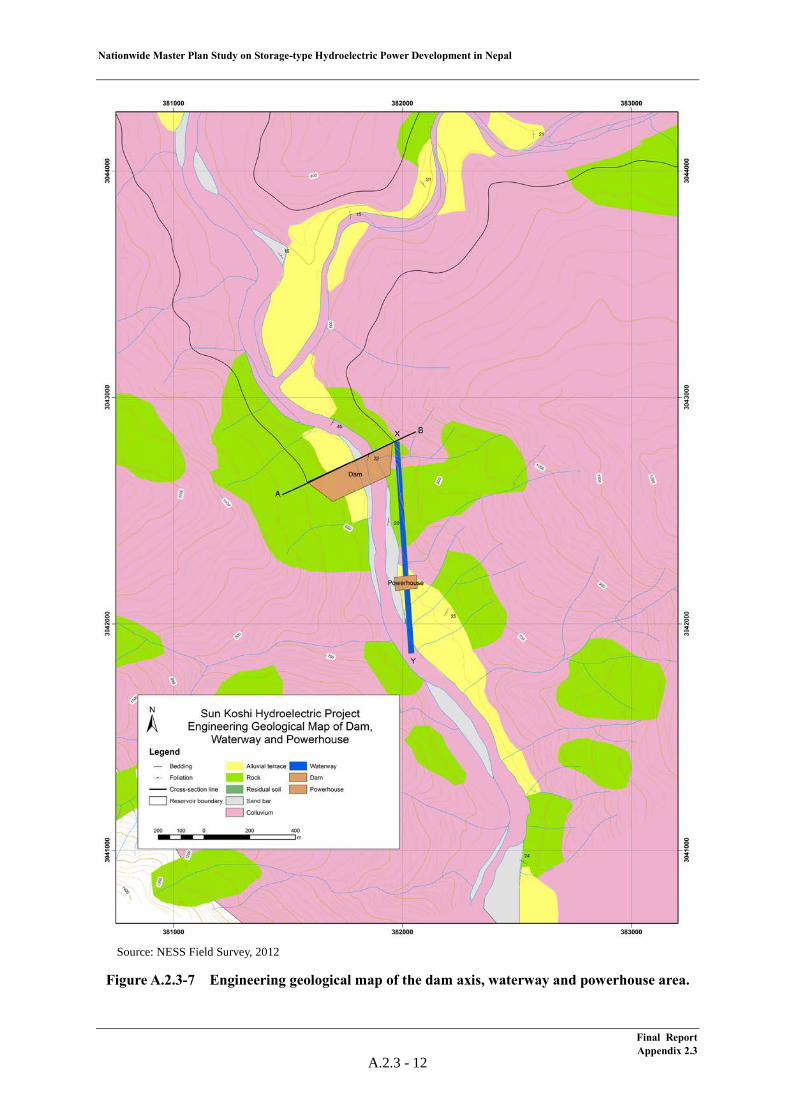
Nationwide Master Plan Study on Storage-type Hydroelectric Power Development in Nepal
Source: NESS Field Survey, 2012
Figure A.2.3-7 Engineering geological map of the dam axis, waterway and powerhouse area.
Final Report Appendix 2.3
A.2.3 - 12
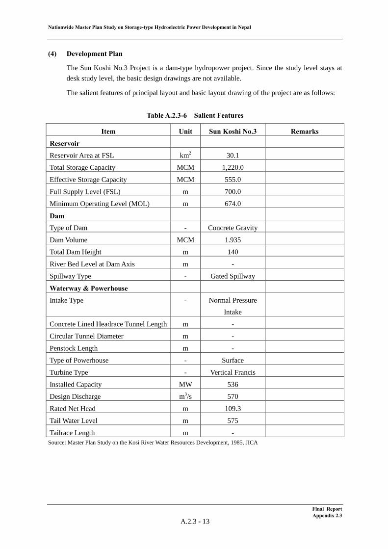
Nationwide Master Plan Study on Storage-type Hydroelectric Power Development in Nepal
(4) Development Plan
The Sun Koshi No.3 Project is a dam-type hydropower project. Since the study level stays at desk study level, the basic design drawings are not available.
The salient features of principal layout and basic layout drawing of the project are as follows:
Table A.2.3-6 Salient Features
Item Unit Sun Koshi No.3 Remarks
Reservoir
Reservoir Area at FSL km2 30.1
Total Storage Capacity MCM 1,220.0
Effective Storage Capacity MCM 555.0
Full Supply Level (FSL) m 700.0
Minimum Operating Level (MOL) m 674.0
Dam
Type of Dam - Concrete Gravity
Dam Volume MCM 1.935
Total Dam Height m 140
River Bed Level at Dam Axis m -
Spillway Type - Gated Spillway
Waterway & Powerhouse
Intake Type - Normal Pressure Intake
Concrete Lined Headrace Tunnel Length m -
Circular Tunnel Diameter m -
Penstock Length m -
Type of Powerhouse - Surface
Turbine Type - Vertical Francis
Installed Capacity MW 536
Design Discharge m3/s 570
Rated Net Head m 109.3
Tail Water Level m 575
Tailrace Length m - Source: Master Plan Study on the Kosi River Water Resources Development, 1985, JICA
Final Report Appendix 2.3
A.2.3 - 13
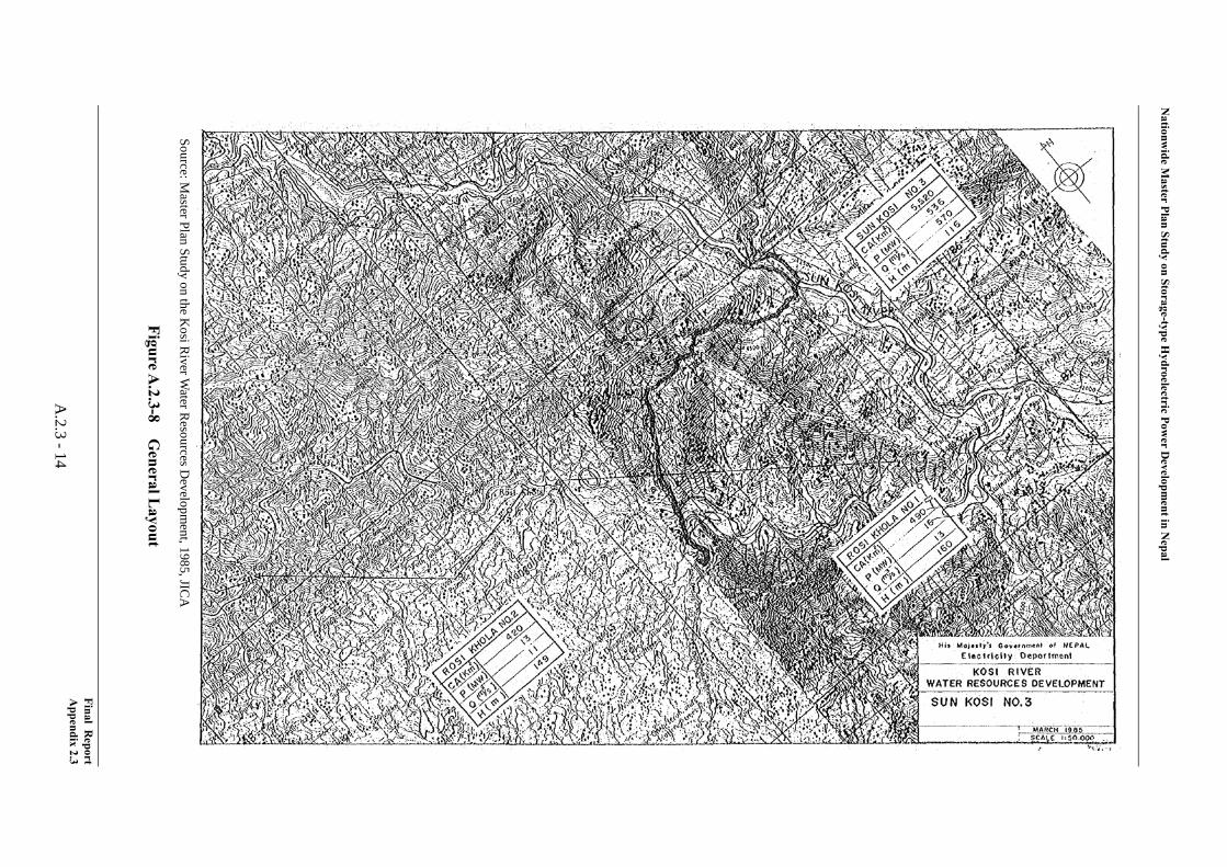
Nationw
ide Master Plan Study on Storage-type H
ydroelectric Power D
evelopment in N
epal
Source: Master Plan Study on the K
osi River W
ater Resources D
evelopment, 1985, JIC
A
Figure A.2.3-8
General L
ayout
Final Report
Appendix 2.3
A.2.3 -14
Nationwide Master Plan Study on Storage-type Hydroelectric Power Development in Nepal
Further, the findings attained by the Study Team through the site reconnaissance conducted in June, 2012 in terms of the dam site and powerhouse site are summarized below.
Dam site
The dam site proposed in “Master Plan Study on the Koshi River Water Resources Development (1985)” conducted by JICA is located at approximately 1 km upstream of the Chiyantar village, 9 km of the Nepalthok town. The coordinate at dam axis is approximately 27º29’51”N, 85º48’06”E and river bed elevation is 575 m.
The both left bank and right bank are steep slopes with the height of more than 400 m from the river bed.
There is an unpaved road (Direct Distance: 5.5 km) at the right bank from the Nepalthok town located at the confluence of the Sun Koshi river and its tributary, the Roshi Khola river to the vicinity of the dam site. However, a new 150 m bridge will be required at around the existing suspension bridge over the Roshi Khola river, as it is impossible to cross the river in rainy seasons due to lack of the bridge which enables car transportation. Furthermore, as the paved road is on the high location from the river bed, it is necessary to construct some branch roads toward the river bed.
Powerhouse site
Although the location of powerhouse is not clearly shown in the Master Plan report, a site 1 km downstream of the dam site close to the Chiyantar village at the left bank is studied by the NEA.
Others
In the present layout, the FSL of the Sun Koshi No.3 project is EL.700 m and the length of the reservoir extends approximately 30 km. In the upstream Dolaghat town, there are bridges over the Indrawati river and the Botekoshi river of which elevation is approximately EL.630 m, as a part of the Anrico highway connecting Nepal and China. Therefore, the bridges and 6 km of the highway are to be inundated.
It would be an alternative to develop the project by lowering FSL down to EL.620m as run of river scheme in order to minimize the impact of inundation. However, it would be difficult to keep the dead volume for sediment in the reservoir and to flush sediment due to the gentle inclination of river bed. Therefore, the countermeasure for sediment would be a challenge in this alternative.
With regard to the Sun Koshi No.3 project, a feasibility study will be started in FY2013 by the NEA.
Final Report Appendix 2.3
A.2.3 - 15
Nationwide Master Plan Study on Storage-type Hydroelectric Power Development in Nepal
(5) Electrical/Mechanical Equipment and Transmission Line
1) General
Rated effective head, power discharge and installed capacity of the Sun Koshi No.3 Project are as follows;
Rated Effective Head : 109.30 m Rated Power Discharge : 570 m3/s Installed Capacity : 536 MW
The HD Wiz (developed by J-POWER, based on existing hydropower plant data around world) has been used for reviewing design of electrical/mechanical equipment taking above information into consideration. Turbine efficiency and generator efficiency have been improved in recent years and installed capacity exceeded above-mentioned 536 MW consequently.
2) Unit Capacity and Number of Unit
Generally, for the turbine-generator, a large unit capacity is said to be more economical merits of scale. However, optimum unit capacity of the turbine-generator is determined in consideration of influence to the power system, development timing and transportation restriction.
In this project, all electrical and mechanical equipment will be transporting from foreign countries via Indian national road and un-maintained Nepalese national road to the project site. Therefore maximum unit capacity shall be set as around 100 MW and number of 6 units plan has been adopted for the project.
3) Turbine
a) Turbine Output
Rated turbine output at rated effective head of 109.30m and rated power discharge of 95.00 m3/s per unit can be calculated as follow;
Pt = 9.8 × Hn × Qt × ηt = 9.8 × 109.30 × 95.00 × 0.925 ≈ 94,100kW where Pt : Rated turbine output per unit (kW) Hn : Rated effective head (m) Qt : Rated power discharge per unit (m3/s) ηt : Turbine efficiency
b) Type of Turbine
Generally, type of turbine can be determined by close relation between effective head and turbine output. Vertical shaft Francis type turbine can be selected taking rated effective head and turbine output into consideration.
Final Report Appendix 2.3
A.2.3 - 16
Nationwide Master Plan Study on Storage-type Hydroelectric Power Development in Nepal
c) Runner Material
Stainless steel anti-corrosion type such as 13 chrome high nickels stainless steel is recommended to be applied for the runner material. Surface of runner and wear ring shall be coated (hard or soft) in case of water quality. Detailed coating method shall be specified in the detailed design stage.
d) Installed Capacity
Installed capacity can be calculated from aforementioned turbine output per unit as follow;
94,100 kW × 6 = 564,600 kW
Review of energy calculation is conducted by using above installed capacity.
4) Generator
A three phase alternating current synchronous generator with vertical shaft rated capacity of 102,300 kVA and power factor of 90% lag are selected.
a) Generator Capacity
Rated generator capacity can be calculated from rated turbine output, power factor and generator efficiency as follows;
Pg = Pt × ηg / p.f (kVA) =94,100 × 0.979 / 0.90 ≈102,300 kVA where Pg : Rated generator capacity (kVA) Pt : Rated turbine output (kW) ηg : Generator efficiency p.f : Power factor, lag
As the results of above calculation, rated generator capacity is 102,300 kVA.
5) Transmission Line
Regarding designing of the transmission line, transmission line shall be connected to the closest substation based on 400 kV Transmission Line Power Development Plan by the NEA. And also thermal capacity and maximum surface potential gradient have been taken into consideration for designing of the transmission line and following specifications have been adopted. As for the transmission line length, the direct length from project area to closest substation was measured from map. Therefore, some allowance has been taken into consideration.
Connected Substation : Barhabise Substation Transmission Line Voltage : 220 kV Length of Transmission Line : 35 km Conductor Type : Moose × 2, 2 circuits
Final Report Appendix 2.3
A.2.3 - 17

2.4 Lower Badigad Project (C-02)
Nationwide Master Plan Study on Storage-type Hydroelectric Power Development in Nepal
Table of Contents
(1) Project Summary ................................................................................................................... 1 (2) Meteorology & Hydrology .................................................................................................... 6 (3) Geology ................................................................................................................................. 7
(4) Development Plan ................................................................................................................. 10 (5) Electrical/Mechanical Equipment and Transmission Line .................................................... 13
List of Tables
Table A.2.4-1 Project Description ................................................................................................ 4 Table A.2.4-2 Monthly Rainfall at the Tamghas Station .............................................................. 6 Table A.2.4-3 Flow data of the Lower Badigad Project ............................................................... 6 Table A.2.4-4 Life of Reservoir .................................................................................................... 7 Table A.2.4-5 Salient Features...................................................................................................... 10
List of Figures
Figure A.2.4-1 Location of the Lower Badigad Project (C-02) .................................................... 3 Figure A.2.4-2 General Layout of the Lower Badigad Project (C-02) ......................................... 3 Figure A.2.4-3 Land Use and Buildings in the Reservoir Area of the Lower Badigad Project .... 5 Figure A.2.4-4 Geological map of the project area ...................................................................... 8 Figure A.2.4-5 Engineering geological map of the reservoir and its surrounding region ............ 9 Figure A.2.4-6 General Layout ..................................................................................................... 11
Final Report Appendix 2.3
Nationwide Master Plan Study on Storage-type Hydroelectric Power Development in Nepal
A.2.4 Lower Badigad (C-02)
(1) Project Summary
The Lower Badigad Project is a 380.3 MW storage-type hydroelectric power project located at the Badigad river in Gulmi District in the central region. The latest study for this project was conducted in the “Update and Review of Identification and Feasibility Study of Storage Project, 2002, NEA.” The study level for this project stays at the desk study level.
Further, the JICA Study Team conducted a site reconnaissance at Lower Badigad project site in June 2012. The findings attained through site reconnaissance are also summarized in this clause.
As hydrological characteristics, the annual rainfall at the Tamghas gauging station nearest to the project site is 1,879 mm and the average river discharge at the dam site is 83.7 m3/s. The drainage area is 2,050 km2, and the specific sediment volume is estimated to be 2,526 t/km2/year. This is larger than 4,400 t/km2/year, which is the value adopted by the NEA as average specific sedimentation volume in the central region. No glacier lakes having a high risk of a GLOF are identified in the drainage basin.
From a geological view point, the project area lies in the Lesser Himalaya Zone and is composed mainly of quartzite, slate, phyllite and limestone. There is an active fault (named the Badigad Fault) along the Badigad River. The reservoir area is underlain mainly by slate and limestone. Limestone is limited in the reservoir area and would not affect water tightness. However, there is a major active landslide named Gultung Pahiro, which is located in the area surrounding the reservoir area and provides a large volume of sediment. The dam site is underlain by quartzite and slate, but it is crossed by the active Badigad Fault. The headrace tunnel route passes through slate and quartzite, which form hard and compact rock. Power house site is underlain mainly by slate. It is covered with thick river deposits. The project area is located in the area where a relatively small acceleration of 170mgal is shown on the seismic hazard map. It is away from a large tectonic thrust (MBT) at a long distance of 25km, but an active fault (the Badigad Fault) crosses the dam site. It is away from epicenters larger than M4 at a long distance of 30km.
The impact on the Natural Environment is average and the impact on the Social Environment is high. Lower Badigad is located in the Gandaki River Basin. The reservoir area is 13.7 km2. There are three protected areas downstream of the river and five important species which depend on water habitat that are known. The length of the Transmission Line is relatively short at 49 km. The number of resettlements is the highest at 1,606. The number of resettlements per unit generation is the biggest at 4.22 HH/MW. The number of affected industries is also the highest at 11. The number of Indigenous groups is 7 (Newar (Advanced), Thakali (Advanced), Magar (Disadvantaged), Gurung (Disadvantaged), Tharu (Marginalised), Bote (Highly Marginalised), Majhi (Highly Marginalised)) which is the highest. The affected agricultural land is 5.9 km2 which is relatively large. The affected irrigation systems are 58, which is the highest. The number of the fishermen is 217, which is relatively high. 26.1 km drivable roads, 11 suspension bridges, 2 micro hydropower plants and 29 water supply schemes will be affected.
From the view point of hydropower planning, the proposed rockfill dam with a height of 191 m
Final Report Appendix 2.4
A.2.4 - 1
Nationwide Master Plan Study on Storage-type Hydroelectric Power Development in Nepal
makes a large effective reservoir volume of 505 million m3. The rated power discharge of 233 m3/s is required to gain 380 MW of installed capacity with an effective head of 192.5 m. Although the specific sediment yield for the Lower Badigad project is estimated from that for Andhi Khola project located adjacent to Lower Badigad, there is a possibility that the actual specific sediment yield would be substantially larger than the estimation since a large-scale land slide is confirmed in the reservoir as a result of the site reconnaissance. Therefore, a sand flushing facility such as that adopted in the Tanahu project, which enables flushing out the sediment, has to be planned. Furthermore, the dam type that enables installing such a sand flushing facility in the dam also has to be studied.
The location, basic layout and salient features of the project are shown below.
Final Report Appendix 2.4
A.2.4 - 2
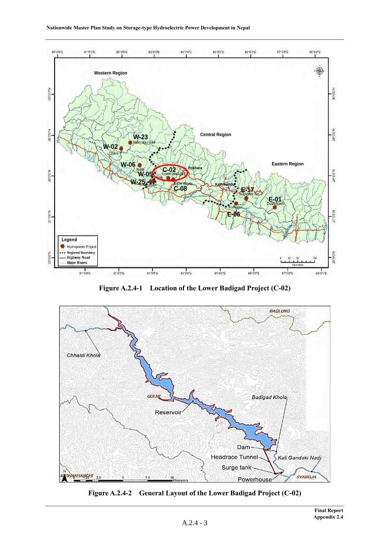
Nationwide Master Plan Study on Storage-type Hydroelectric Power Development in Nepal
Figure A.2.4-1 Location of the Lower Badigad Project (C-02)
Figure A.2.4-2 General Layout of the Lower Badigad Project (C-02)
Western Region
Central Region
Eastern RegionPokhara
Kathmandu
Regional Boundary
W-23W-02
W-06
W-25W-05 C-02
C-08E-01
E-17
E-06
Western Region
Central Region
Eastern RegionPokhara
Kathmandu
Regional BoundaryRegional Boundary
W-23W-02
W-06
W-25W-05 C-02
C-08E-01
E-17
E-06
Final Report Appendix 2.4
A.2.4 - 3
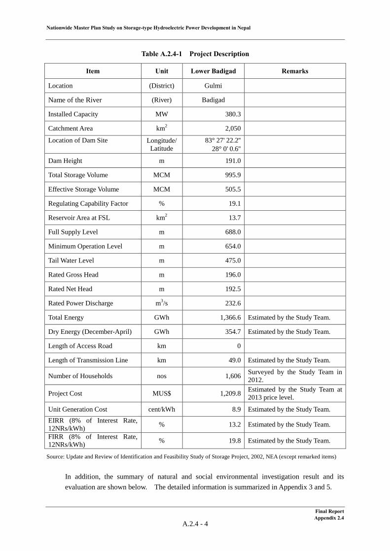
Nationwide Master Plan Study on Storage-type Hydroelectric Power Development in Nepal
Table A.2.4-1 Project Description
Item Unit Lower Badigad Remarks
Location (District) Gulmi
Name of the River (River) Badigad
Installed Capacity MW 380.3
Catchment Area km2 2,050
Location of Dam Site
Longitude/ Latitude
83° 27' 22.2'' 28° 0' 0.6''
Dam Height m 191.0
Total Storage Volume MCM 995.9
Effective Storage Volume MCM 505.5
Regulating Capability Factor % 19.1
Reservoir Area at FSL km2 13.7
Full Supply Level m 688.0
Minimum Operation Level m 654.0
Tail Water Level m 475.0
Rated Gross Head m 196.0
Rated Net Head m 192.5
Rated Power Discharge m3/s 232.6
Total Energy GWh 1,366.6 Estimated by the Study Team.
Dry Energy (December-April) GWh 354.7 Estimated by the Study Team.
Length of Access Road km 0
Length of Transmission Line km 49.0 Estimated by the Study Team.
Number of Households nos 1,606 Surveyed by the Study Team in 2012.
Project Cost MUS$ 1,209.8 Estimated by the Study Team at 2013 price level.
Unit Generation Cost cent/kWh 8.9 Estimated by the Study Team. EIRR (8% of Interest Rate, 12NRs/kWh) % 13.2 Estimated by the Study Team.
FIRR (8% of Interest Rate, 12NRs/kWh) % 19.8 Estimated by the Study Team.
Source: Update and Review of Identification and Feasibility Study of Storage Project, 2002, NEA (except remarked items)
In addition, the summary of natural and social environmental investigation result and its evaluation are shown below. The detailed information is summarized in Appendix 3 and 5.
Final Report Appendix 2.4
A.2.4 - 4
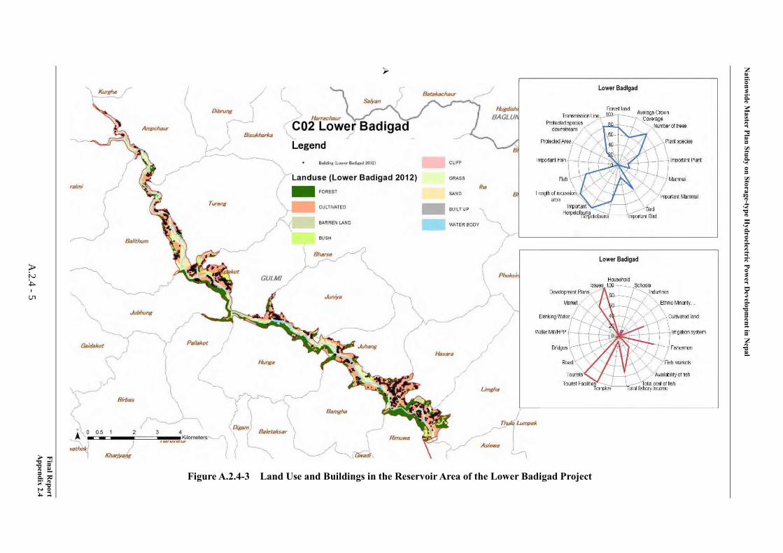
Nationw
ide Master Plan Study on Storage-type H
ydroelectric Power D
evelopment in N
epal
Final Report
Appendix 2.4
A.2.4 -5
Figure A.2.4-3 Land Use and Buildings in the Reservoir Area of the Lower Badigad Project
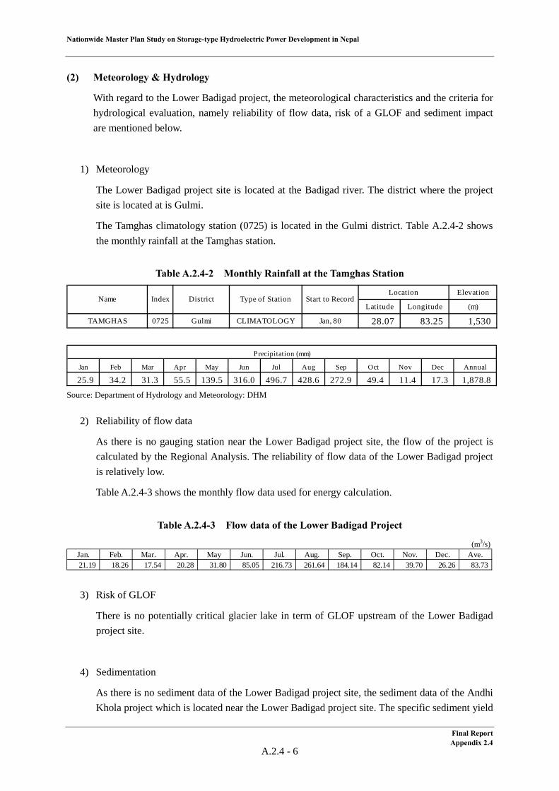
Nationwide Master Plan Study on Storage-type Hydroelectric Power Development in Nepal
(2) Meteorology & Hydrology
With regard to the Lower Badigad project, the meteorological characteristics and the criteria for hydrological evaluation, namely reliability of flow data, risk of a GLOF and sediment impact are mentioned below.
1) Meteorology
The Lower Badigad project site is located at the Badigad river. The district where the project site is located at is Gulmi.
The Tamghas climatology station (0725) is located in the Gulmi district. Table A.2.4-2 shows the monthly rainfall at the Tamghas station.
Table A.2.4-2 Monthly Rainfall at the Tamghas Station
Source: Department of Hydrology and Meteorology: DHM
2) Reliability of flow data
As there is no gauging station near the Lower Badigad project site, the flow of the project is calculated by the Regional Analysis. The reliability of flow data of the Lower Badigad project is relatively low.
Table A.2.4-3 shows the monthly flow data used for energy calculation.
Table A.2.4-3 Flow data of the Lower Badigad Project
3) Risk of GLOF
There is no potentially critical glacier lake in term of GLOF upstream of the Lower Badigad project site.
4) Sedimentation
As there is no sediment data of the Lower Badigad project site, the sediment data of the Andhi Khola project which is located near the Lower Badigad project site. The specific sediment yield
Elevation
Latitude Longitude (m)
TAMGHAS 0725 Gulmi CLIMATOLOGY Jan, 80 28.07 83.25 1,530
Start to RecordName Index DistrictLocation
Type of Station
Jan Feb Mar Apr May Jun Jul Aug Sep Oct Nov Dec Annual
25.9 34.2 31.3 55.5 139.5 316.0 496.7 428.6 272.9 49.4 11.4 17.3 1,878.8
Precipitation (mm)
(m3/s)Jan. Feb. Mar. Apr. May Jun. Jul. Aug. Sep. Oct. Nov. Dec. Ave.21.19 18.26 17.54 20.28 31.80 85.05 216.73 261.64 184.14 82.14 39.70 26.26 83.73
Final Report Appendix 2.4
A.2.4 - 6
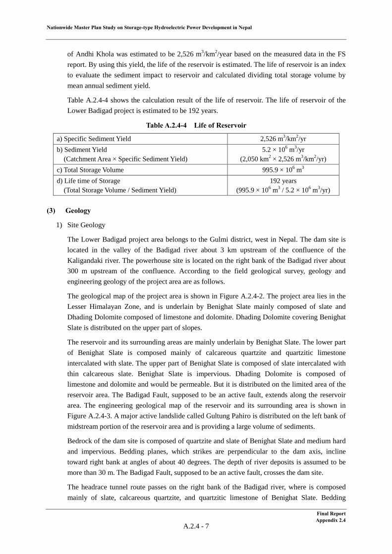
Nationwide Master Plan Study on Storage-type Hydroelectric Power Development in Nepal
of Andhi Khola was estimated to be 2,526 m3/km2/year based on the measured data in the FS report. By using this yield, the life of the reservoir is estimated. The life of reservoir is an index to evaluate the sediment impact to reservoir and calculated dividing total storage volume by mean annual sediment yield.
Table A.2.4-4 shows the calculation result of the life of reservoir. The life of reservoir of the Lower Badigad project is estimated to be 192 years.
Table A.2.4-4 Life of Reservoir
a) Specific Sediment Yield 2,526 m3/km2/yr b) Sediment Yield (Catchment Area × Specific Sediment Yield)
5.2 × 10⁶ m3/yr (2,050 km2 × 2,526 m3/km2/yr)
c) Total Storage Volume 995.9 × 10⁶ m3 d) Life time of Storage (Total Storage Volume / Sediment Yield)
192 years (995.9 × 10⁶ m3 / 5.2 × 10⁶ m3/yr)
(3) Geology
1) Site Geology
The Lower Badigad project area belongs to the Gulmi district, west in Nepal. The dam site is located in the valley of the Badigad river about 3 km upstream of the confluence of the Kaligandaki river. The powerhouse site is located on the right bank of the Badigad river about 300 m upstream of the confluence. According to the field geological survey, geology and engineering geology of the project area are as follows.
The geological map of the project area is shown in Figure A.2.4-2. The project area lies in the Lesser Himalayan Zone, and is underlain by Benighat Slate mainly composed of slate and Dhading Dolomite composed of limestone and dolomite. Dhading Dolomite covering Benighat Slate is distributed on the upper part of slopes.
The reservoir and its surrounding areas are mainly underlain by Benighat Slate. The lower part of Benighat Slate is composed mainly of calcareous quartzite and quartzitic limestone intercalated with slate. The upper part of Benighat Slate is composed of slate intercalated with thin calcareous slate. Benighat Slate is impervious. Dhading Dolomite is composed of limestone and dolomite and would be permeable. But it is distributed on the limited area of the reservoir area. The Badigad Fault, supposed to be an active fault, extends along the reservoir area. The engineering geological map of the reservoir and its surrounding area is shown in Figure A.2.4-3. A major active landslide called Gultung Pahiro is distributed on the left bank of midstream portion of the reservoir area and is providing a large volume of sediments.
Bedrock of the dam site is composed of quartzite and slate of Benighat Slate and medium hard and impervious. Bedding planes, which strikes are perpendicular to the dam axis, incline toward right bank at angles of about 40 degrees. The depth of river deposits is assumed to be more than 30 m. The Badigad Fault, supposed to be an active fault, crosses the dam site.
The headrace tunnel route passes on the right bank of the Badigad river, where is composed mainly of slate, calcareous quartzite, and quartzitic limestone of Benighat Slate. Bedding
Final Report Appendix 2.4
A.2.4 - 7
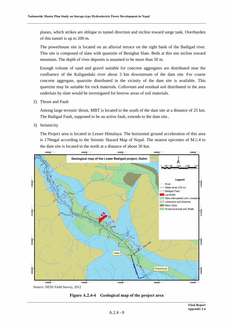
Nationwide Master Plan Study on Storage-type Hydroelectric Power Development in Nepal
planes, which strikes are oblique to tunnel direction and incline toward surge tank. Overburden of this tunnel is up to 200 m.
The powerhouse site is located on an alluvial terrace on the right bank of the Badigad river. This site is composed of slate with quartzite of Benighat Slate. Beds at this site incline toward mountain. The depth of river deposits is assumed to be more than 50 m.
Enough volume of sand and gravel suitable for concrete aggregates are distributed near the confluence of the Kaligandaki river about 3 km downstream of the dam site. For coarse concrete aggregate, quartzite distributed in the vicinity of the dam site is available. This quartzite may be suitable for rock materials. Colluvium and residual soil distributed in the area underlain by slate would be investigated for borrow areas of soil materials.
2) Thrust and Fault
Among large tectonic thrust, MBT is located to the south of the dam site at a distance of 25 km. The Badigad Fault, supposed to be an active fault, extends to the dam site..
3) Seismicity
The Project area is located in Lesser Himalaya. The horizontal ground acceleration of this area is 170mgal according to the Seismic Hazard Map of Nepal. The nearest epicenter of M≧4 to the dam site is located to the north at a distance of about 30 km.
Source: NESS Field Survey, 2012
Figure A.2.4-4 Geological map of the project area
Final Report Appendix 2.4
A.2.4 - 8
Nationwide Master Plan Study on Storage-type Hydroelectric Power Development in Nepal
Source: NESS Field Survey, 2012
Figure A.2.4-5 Engineering geological map of the reservoir and its surrounding region
Final Report Appendix 2.4
A.2.4 - 9
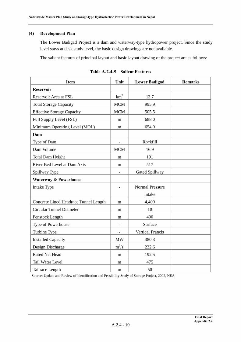
Nationwide Master Plan Study on Storage-type Hydroelectric Power Development in Nepal
(4) Development Plan
The Lower Badigad Project is a dam and waterway-type hydropower project. Since the study level stays at desk study level, the basic design drawings are not available.
The salient features of principal layout and basic layout drawing of the project are as follows:
Table A.2.4-5 Salient Features
Item Unit Lower Badigad Remarks
Reservoir
Reservoir Area at FSL km2 13.7
Total Storage Capacity MCM 995.9
Effective Storage Capacity MCM 505.5
Full Supply Level (FSL) m 688.0
Minimum Operating Level (MOL) m 654.0
Dam
Type of Dam - Rockfill
Dam Volume MCM 16.9
Total Dam Height m 191
River Bed Level at Dam Axis m 517
Spillway Type - Gated Spillway
Waterway & Powerhouse
Intake Type - Normal Pressure Intake
Concrete Lined Headrace Tunnel Length m 4,400
Circular Tunnel Diameter m 10
Penstock Length m 400
Type of Powerhouse - Surface
Turbine Type - Vertical Francis
Installed Capacity MW 380.3
Design Discharge m3/s 232.6
Rated Net Head m 192.5
Tail Water Level m 475
Tailrace Length m 50 Source: Update and Review of Identification and Feasibility Study of Storage Project, 2002, NEA
Final Report Appendix 2.4
A.2.4 - 10
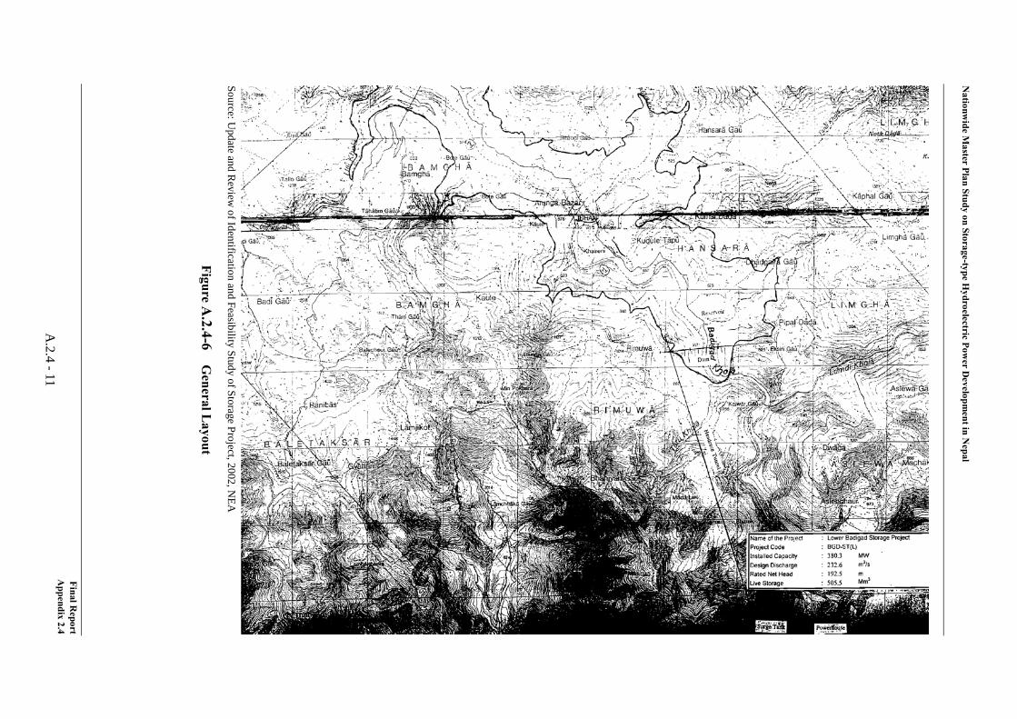
Nationw
ide Master Plan Study on Storage-type H
ydroelectric Power D
evelopment in N
epal
Source: Update and R
eview of Identification and Feasibility Study of Storage Project, 2002, N
EA
Figure A.2.4-6
General L
ayout
Final Report
Appendix 2.4
A.2.4 -11
Nationwide Master Plan Study on Storage-type Hydroelectric Power Development in Nepal
Further, the findings attained by the Study Team through the site reconnaissance conducted in June, 2012 in terms of dam site and powerhouse site are summarized below.
Dam Site
The dam site proposed in the “Update and Review of Identification and Feasibility Study of Storage Project (2002)” is located at approximately 4 km upstream of the confluence of the Kari Gandaki river and the Badigad river. The coordinate at dam axis is approximately 28º00’03”N, 83º27’14”E and river bed elevation is 517 m. The left bank abutment is a ridge of which thickness is approximately 300 m at FSL 688 m and area higher than 630 m is a farm land. The inclination of lower part seems steep, about 30 degree and upper part seems rather gentle according to the topographical map. At the right bank, some outcrop was confirmed at the water’s edge and there are two steps of terraces being farm land above that. The inclination of the upper part seems 20–25 degree and rather gentle compared with the left bank. There is an unpaved road on the left bank, the height from the river bed to the road is approximately 15 m at the dam axis.
There is a large-scale land slide area due to the Badigad fault at the upstream of a creek located at the 6 km upstream left bank from the dam site. A large amount of sediment produced from the land slide area is flowing into the Badigad river. Therefore, it will be a key point for the project how to settle this sediment issue.
On the other hand, the Upper Badigad Storage project is planned at immediately upstream of the Lower Badigad project. The dam site of Upper Badigad project is located at 14 km upstream of the creek, 20 km upstream of the Lower Badigad dam site. In order to avoid above-mentioned sediment problem, it would be an alternative scheme to combine these two projects by moving Lower Badigad dam site from the original location to somewhere between the confluence of the creek and the Upper Badigad dam site and gain some head by constructing a certain length of headrace tunnel. In this case, it would be preferable for the powerhouse to be located at upstream of the creek so that the headrace tunnel will not cross the fault.
Powerhouse Site
The powerhouse site proposed in the “Update and Review of Identification and Feasibility Study of Storage Project (2002)” is located at the right bank of the Badigad river, approximately 1 km upstream of the confluence of the Kari Gandaki river and the Badigad river. An alternative powerhouse site at opposite side of the river (left bank) is studied by the NEA. In case that the powerhouse is laid out at the left bank, 300–350 m upstream of the studied site, just upstream of the river’s curving to the right will be more preferable considering the layout of the waterway route though the excavation volume for powerhouse will slightly be larger. The coordinate of the site is approximately 27º58’53”N, 83º07’57”E and river bed elevation is 500 m. The elevation of the existing road is approximately EL.535 m, which enables an easy access. However, a bypass road will be required for the Ridi town if equipment and materials for construction are transported through the Ridi town. Further, as the length of waterway from the dam site to this powerhouse site will exceed 10 km in case that the Lower Badigad dam site is moved to upstream of the creek, to construct powerhouse at this site would be unrealistic.
Final Report Appendix 2.4
A.2.4 - 12
Nationwide Master Plan Study on Storage-type Hydroelectric Power Development in Nepal
(5) Electrical/Mechanical Equipment and Transmission Line
1) General
Rated effective head, power discharge and installed capacity of the Lower Badigad Project are as follows;
Rated Effective Head : 192.50 m Rated Power Discharge : 232.60 m3/s Installed Capacity : 380 MW
The HD Wiz (developed by J-POWER, based on existing hydropower plant data around world) has been used for reviewing design of electrical/mechanical equipment taking above information into consideration. Turbine efficiency and generator efficiency have been improved in recent years and installed capacity exceeded above-mentioned 380 MW consequently.
2) Unit Capacity and Number of Unit
Generally, for the turbine-generator, a large unit capacity is said to be more economical merits of scale. However, optimum unit capacity of the turbine-generator is determined in consideration of influence to the power system, development timing and transportation restriction.
In this project, all electrical and mechanical equipment will be transporting from foreign countries via Indian national road and un-maintained Nepalese national road to the project site. Therefore maximum unit capacity shall be set as around 100 MW and number of 4 units plan has been adopted for the project.
3) Turbine
a) Turbine Output
Rated turbine output at rated effective head of 192.50 m and rated power discharge of 58.15 m3/s per unit can be calculated as follow;
Pt = 9.8 × Hn × Qt × ηt = 9.8 × 192.50 × 58.15 × 0.929 ≈ 101,900 kW where Pt : Rated turbine output per unit (kW) Hn : Rated effective head (m) Qt : Rated power discharge per unit (m3/s) ηt : Turbine efficiency
b) Type of Turbine
Generally, type of turbine can be determined by close relation between effective head and turbine output. Vertical shaft Francis type turbine can be selected taking rated effective head and turbine output into consideration.
Final Report Appendix 2.4
A.2.4 - 13
Nationwide Master Plan Study on Storage-type Hydroelectric Power Development in Nepal
c) Runner Material
Stainless steel anti-corrosion type such as 13 chrome high nickels stainless steel is recommended to be applied for the runner material. Surface of runner and wear ring shall be coated (hard or soft) in case of water quality. Detailed coating method shall be specified in the detailed design stage.
d) Installed Capacity
Installed capacity can be calculated from aforementioned turbine output per unit as follow;
101,900 kW × 4 = 407,600 kW
Review of energy calculation is conducted by using above installed capacity.
4) Generator
A three phase alternating current synchronous generator with vertical shaft rated capacity of 110,700 kVA and power factor of 90% lag are selected.
a) Generator Capacity
Rated generator capacity can be calculated from rated turbine output, power factor and generator efficiency as follows;
Pg = Pt × ηg / p.f (kVA) = 101,900 × 0.978 / 0.90 ≈ 110,700 kVA where Pg : Rated generator capacity (kVA) Pt : Rated turbine output (kW) ηg : Generator efficiency p.f : Power factor, lag
As the results of above calculation, rated generator capacity is 110,700 kVA.
5) Transmission Line
Regarding designing of the transmission line, transmission line shall be connected to the closest substation based on 400 kV Transmission Line Power Development Plan by the NEA. And also thermal capacity and maximum surface potential gradient have been taken into consideration for designing of the transmission line and following specifications have been adopted. As for the transmission line length, the direct length from project area to closest substation was measured from map. Therefore, some allowance has been taken into consideration.
Connected Substation : Butwal Substation Transmission Line Voltage : 220 kV Length of Transmission Line : 49 km Conductor Type : Bison × 2, 2 circuits
Final Report Appendix 2.4
A.2.4 - 14

2.5 Andhi Khola Project (C-08)
Nationwide Master Plan Study on Storage-type Hydroelectric Power Development in Nepal
Table of Contents
(1) Project Summary ................................................................................................................... 1 (2) Meteorology & Hydrology .................................................................................................... 6 (3) Geology ................................................................................................................................. 7
(4) Development Plan .................................................................................................................. 10 (5) Electrical/Mechanical Equipment and Transmission Line .................................................... 17
List of Tables
Table A.2.5-1 Project Description ................................................................................................. 4 Table A.2.5-2 Monthly Rainfall at the Chapkot Station ................................................................ 6 Table A.2.5-3 Flow Data of the Andi Khola Project ..................................................................... 6 Table A.2.5-4 Life of Reservoir .................................................................................................... 7 Table A.2.5-5 Salient Features ...................................................................................................... 10
List of Figures
Figure A.2.5-1 Location of the Andhi Khola Project (C-08) ........................................................ 3 Figure A.2.5-2 General Layout of the Andhi Khola Project (C-08) .............................................. 3 Figure A.2.5-3 Land Use and Buildings in the Reservoir Area of the Andhi Khola Project ......... 5 Figure A.2.5-4 Regional geological map of the project area. ....................................................... 8 Figure A.2.5-5 Engineering geological map of the reservoir and its surrounding area. ............... 9 Figure A.2.5-6 General Layout ..................................................................................................... 11 Figure A.2.5-7 Dam Plan .............................................................................................................. 12 Figure A.2.5-8 Dam Section ......................................................................................................... 13 Figure A.2.5-9 Powerhouse Plan................................................................................................... 14 Figure A.2.5-10 Powerhouse Section ............................................................................................ 15
Final Report Appendix 2.5
Nationwide Master Plan Study on Storage-type Hydroelectric Power Development in Nepal
A.2.5 Andhi Khola (C-08)
(1) Project Summary
The Andhi Khola Project is a 180 MW storage-type hydroelectric power project located in the Syangja District in the central region. The intake is located at the Andhi Khola river and the outlet is located at the Kali Gandaki river. The latest study for this project was conducted in the “Feasibility Study on the Andhi Khola Hydroelectric Project, 2002, NEA.” The study level for this project attains the Feasibility Study level.
Further, the Study Team conducted a site reconnaissance at Andhi Khola project site in June 2012. The findings attained through site reconnaissance are also summarized in this clause.
As hydrological characteristics, the annual rainfall at the Chapkot gauging station nearest to the project site is 1,837 mm and the average river discharge at the dam site is 30.1 m3/s. The drainage area is 4,750 km2, and the specific sediment volume is estimated to be 2,526 t/km2/year. This is larger than 4,400 t/km2/year, which is the value adopted by the NEA as average specific sedimentation volume in the central region. No glacier lakes having a high risk of a GLOF are identified in the drainage basin.
From a geological view point, the project area lies in the Lesser Himalaya Zone and is composed mainly of slate. The reservoir area is mainly underlain by slate. This area is water tight, but many landslides are distributed on the slopes in its surrounding area. The dam site is underlain by slate, but it is not favorable for a dam site because its left bank is covered with thick deposits. The headrace tunnel route passes through slate, which forms fragile rock. The power house site is underlain by fragile slate. It is covered with thick river deposits. The project area is located in an area where a medium acceleration of 200 mgal is shown on the seismic hazard map. It is away from a large tectonic thrust (MBT) at a long distance of 25 km and from epicenters larger than M4 at a long distance of 40 km.
Both the impact on the Natural Environment and the Social Environment is average. Andhi Khola is located in the Gandaki River Basin and the reservoir area is 5.5 km2. The affected forest area is only 1.51 km2. The number of affected fauna is also low, with numbers such as 12 mammals, 16 birds, and 6 Herpetofauna. The dewatering area is 60 km, which is the longest together with Dudh Koshi. There are three protected areas downstream of the project site and five important species that depend on water are known. The length of the transmission line is 49 km, which is relatively short. The number of resettlement is 542, which is not high, but the resettlement per unit generation is relatively high at 3.01 HH/MW. The Indigenous groups in the reservoir area are the Newar (Advanced), Magar (Disadvantaged), and Gurung (Disadvantaged).
From the view point of hydropower planning, the location of proposed dam site for 157 m of a Concrete Faced Rockfill Dam (CFRD) has to be reviewed since the geological condition of the left bank of the dam site does not seem suitable as a foundation for a CFRD. The implementation of the Andhi Khola project will decrease inflow to the reservoir and energy production of the Kali Gandaki A project located downstream of the Andhi Khola project. On the other hand, rising of the intake dam is planned at the Kali Gandaki A Hydropower Plant. Therefore, implementation of the Andhi Khola project should be examined comprehensively in
Final Report Appendix 2.5
A.2.5 - 1
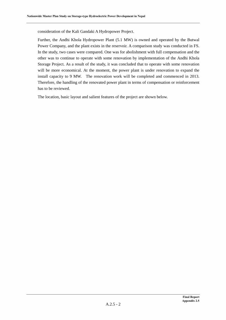
Nationwide Master Plan Study on Storage-type Hydroelectric Power Development in Nepal
consideration of the Kali Gandaki A Hydropower Project.
Further, the Andhi Khola Hydropower Plant (5.1 MW) is owned and operated by the Butwal Power Company, and the plant exists in the reservoir. A comparison study was conducted in FS. In the study, two cases were compared. One was for abolishment with full compensation and the other was to continue to operate with some renovation by implementation of the Andhi Khola Storage Project. As a result of the study, it was concluded that to operate with some renovation will be more economical. At the moment, the power plant is under renovation to expand the install capacity to 9 MW. The renovation work will be completed and commenced in 2013. Therefore, the handling of the renovated power plant in terms of compensation or reinforcement has to be reviewed.
The location, basic layout and salient features of the project are shown below.
Final Report Appendix 2.5
A.2.5 - 2
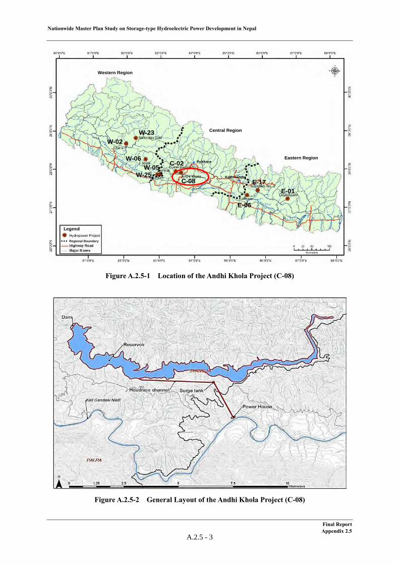
Nationwide Master Plan Study on Storage-type Hydroelectric Power Development in Nepal
Figure A.2.5-1 Location of the Andhi Khola Project (C-08)
Figure A.2.5-2 General Layout of the Andhi Khola Project (C-08)
Western Region
Central Region
Eastern RegionPokhara
Kathmandu
Regional Boundary
W-23W-02
W-06
W-25W-05 C-02
C-08E-01
E-17
E-06
Western Region
Central Region
Eastern RegionPokhara
Kathmandu
Regional BoundaryRegional Boundary
W-23W-02
W-06
W-25W-05 C-02
C-08E-01
E-17
E-06
Final Report Appendix 2.5
A.2.5 - 3
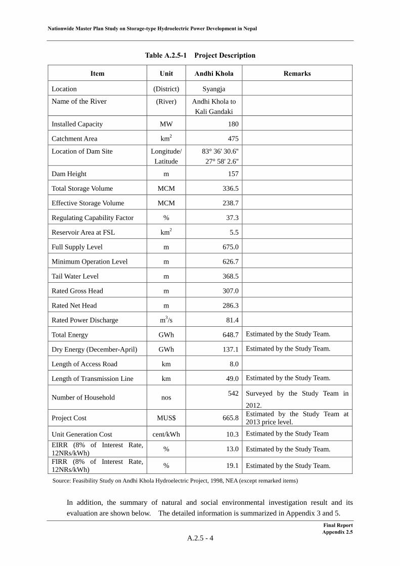
Nationwide Master Plan Study on Storage-type Hydroelectric Power Development in Nepal
Table A.2.5-1 Project Description
Item Unit Andhi Khola Remarks
Location (District) Syangja
Name of the River (River) Andhi Khola to Kali Gandaki
Installed Capacity MW 180
Catchment Area km2 475
Location of Dam Site
Longitude/ Latitude
83° 36' 30.6'' 27° 58' 2.6''
Dam Height m 157
Total Storage Volume MCM 336.5
Effective Storage Volume MCM 238.7
Regulating Capability Factor % 37.3
Reservoir Area at FSL km2 5.5
Full Supply Level m 675.0
Minimum Operation Level m 626.7
Tail Water Level m 368.5
Rated Gross Head m 307.0
Rated Net Head m 286.3
Rated Power Discharge m3/s 81.4
Total Energy GWh 648.7 Estimated by the Study Team.
Dry Energy (December-April) GWh 137.1 Estimated by the Study Team.
Length of Access Road km 8.0
Length of Transmission Line km 49.0 Estimated by the Study Team.
Number of Household nos 542 Surveyed by the Study Team in
2012.
Project Cost MUS$ 665.8 Estimated by the Study Team at 2013 price level.
Unit Generation Cost cent/kWh 10.3 Estimated by the Study Team EIRR (8% of Interest Rate, 12NRs/kWh) % 13.0 Estimated by the Study Team.
FIRR (8% of Interest Rate, 12NRs/kWh) % 19.1 Estimated by the Study Team.
Source: Feasibility Study on Andhi Khola Hydroelectric Project, 1998, NEA (except remarked items)
In addition, the summary of natural and social environmental investigation result and its evaluation are shown below. The detailed information is summarized in Appendix 3 and 5.
Final Report Appendix 2.5
A.2.5 - 4
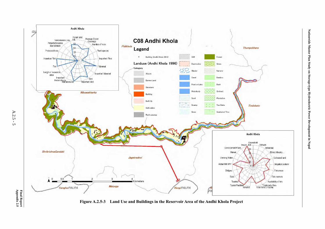
Nationw
ide Master Plan Study on Storage-type H
ydroelectric Power D
evelopment in N
epal
Final Report
Appendix 2.5
A.2.5 -5
Figure A.2.5-3 Land Use and Buildings in the Reservoir Area of the Andhi Khola Project
Nationwide Master Plan Study on Storage-type Hydroelectric Power Development in Nepal
(2) Meteorology & Hydrology
With regard to the Andhi Khola project, the meteorological characteristics and the criteria for hydrological evaluation, namely reliability of flow data, risk of a GLOF and sediment impact are mentioned below.
1) Meteorology
The Andhi Khola project site is located at the Andhi Khola river. The district where the project site is located at is Syangja.
The Chapkot climatology station (0810) is located in the Syangjya district. Table A.2.5-2 shows the monthly rainfall at the Chapkot station.
Table A.2.5-2 Monthly Rainfall at the Chapkot Station
Source: Department of Hydrology and Meteorology: DHM
2) Reliability of flow data
As the gauging station (415) is located at 1.5 km upstream of the dam axis, multiplying the flow data of the gauging station by the rate of catchment area of the dam site to one of gauging station gives the flow data of the Andhi Khola project. The reliability of flow data of the Andhi Khola project is relatively high.
Table A.2.5-3 shows the monthly flow data used for energy calculation. The latest 10 years flow data do not exist. The period of the existing data is from 1964 to 1991. Therefore, the average monthly flow data measured from 1964 to 1991 is adopted for energy calculation.
Table A.2.5-3 Flow Data of the Andi Khola Project
3) Risk of GLOF
There is no potentially critical glacier lake which may cause a GLOF in the upstream area of the Andhi Khola project site.
Elevation
Latitude Longitude (m)
CHAPKOT 0810 Syangja CLIMATOLOGY Jan, 57 27.88 83.82 460
Start to RecordName Index DistrictLocation
Type of Station
Jan Feb Mar Apr May Jun Jul Aug Sep Oct Nov Dec Annual
23.2 24.4 33.8 57.3 140.7 332.7 520.3 377.7 236.7 68.1 7.2 14.7 1,836.8
Precipitation (mm)
(m3/s)Jan. Feb. Mar. Apr. May Jun. Jul. Aug. Sep. Oct. Nov. Dec. Ave.
4.74 3.85 3.17 2.96 6.31 33.33 99.79 94.10 67.16 26.74 9.87 6.14 29.85
Final Report Appendix 2.5
A.2.5 - 6
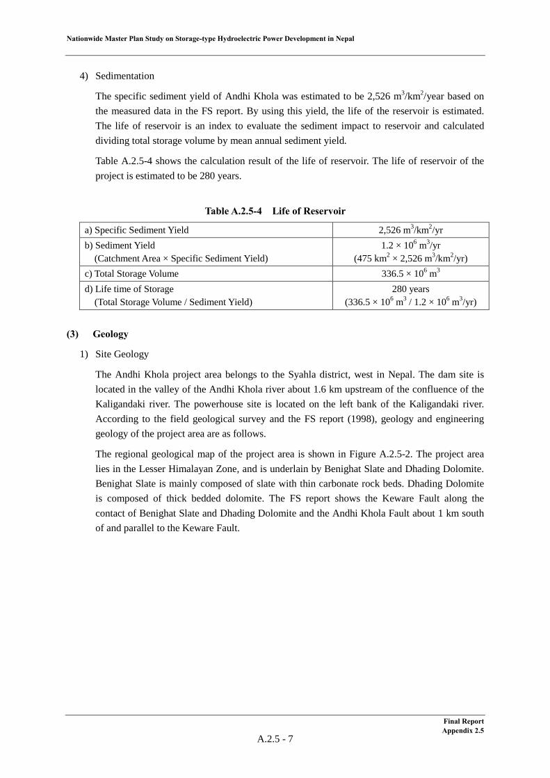
Nationwide Master Plan Study on Storage-type Hydroelectric Power Development in Nepal
4) Sedimentation
The specific sediment yield of Andhi Khola was estimated to be 2,526 m3/km2/year based on the measured data in the FS report. By using this yield, the life of the reservoir is estimated. The life of reservoir is an index to evaluate the sediment impact to reservoir and calculated dividing total storage volume by mean annual sediment yield.
Table A.2.5-4 shows the calculation result of the life of reservoir. The life of reservoir of the project is estimated to be 280 years.
Table A.2.5-4 Life of Reservoir
a) Specific Sediment Yield 2,526 m3/km2/yr b) Sediment Yield (Catchment Area × Specific Sediment Yield)
1.2 × 10⁶ m3/yr (475 km2 × 2,526 m3/km2/yr)
c) Total Storage Volume 336.5 × 10⁶ m3 d) Life time of Storage (Total Storage Volume / Sediment Yield)
280 years (336.5 × 10⁶ m3 / 1.2 × 10⁶ m3/yr)
(3) Geology
1) Site Geology
The Andhi Khola project area belongs to the Syahla district, west in Nepal. The dam site is located in the valley of the Andhi Khola river about 1.6 km upstream of the confluence of the Kaligandaki river. The powerhouse site is located on the left bank of the Kaligandaki river. According to the field geological survey and the FS report (1998), geology and engineering geology of the project area are as follows.
The regional geological map of the project area is shown in Figure A.2.5-2. The project area lies in the Lesser Himalayan Zone, and is underlain by Benighat Slate and Dhading Dolomite. Benighat Slate is mainly composed of slate with thin carbonate rock beds. Dhading Dolomite is composed of thick bedded dolomite. The FS report shows the Keware Fault along the contact of Benighat Slate and Dhading Dolomite and the Andhi Khola Fault about 1 km south of and parallel to the Keware Fault.
Final Report Appendix 2.5
A.2.5 - 7
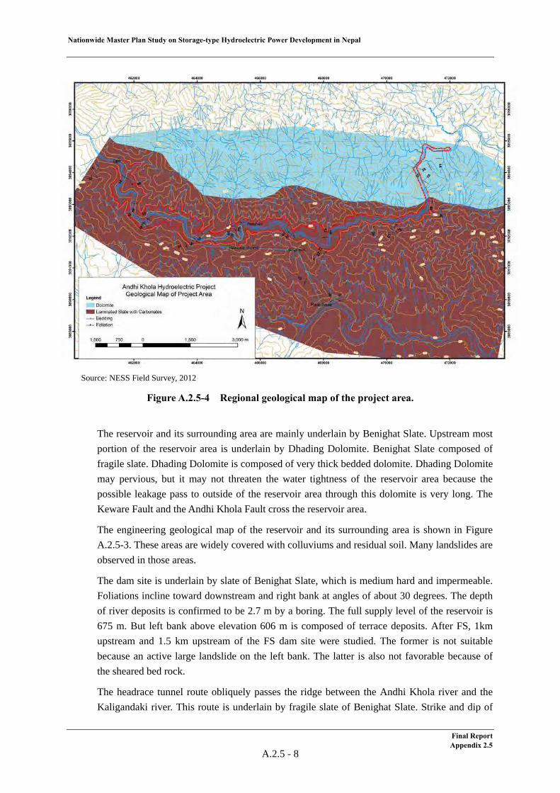
Nationwide Master Plan Study on Storage-type Hydroelectric Power Development in Nepal
Final Report Appendix 2.5
A.2.5 - 8
Source: NESS Field Survey, 2012
Figure A.2.5-4 Regional geological map of the project area.
The reservoir and its surrounding area are mainly underlain by Benighat Slate. Upstream most portion of the reservoir area is underlain by Dhading Dolomite. Benighat Slate composed of fragile slate. Dhading Dolomite is composed of very thick bedded dolomite. Dhading Dolomite may pervious, but it may not threaten the water tightness of the reservoir area because the possible leakage pass to outside of the reservoir area through this dolomite is very long. The Keware Fault and the Andhi Khola Fault cross the reservoir area.
The engineering geological map of the reservoir and its surrounding area is shown in Figure A.2.5-3. These areas are widely covered with colluviums and residual soil. Many landslides are observed in those areas.
The dam site is underlain by slate of Benighat Slate, which is medium hard and impermeable. Foliations incline toward downstream and right bank at angles of about 30 degrees. The depth of river deposits is confirmed to be 2.7 m by a boring. The full supply level of the reservoir is 675 m. But left bank above elevation 606 m is composed of terrace deposits. After FS, 1km upstream and 1.5 km upstream of the FS dam site were studied. The former is not suitable because an active large landslide on the left bank. The latter is also not favorable because of the sheared bed rock.
The headrace tunnel route obliquely passes the ridge between the Andhi Khola river and the Kaligandaki river. This route is underlain by fragile slate of Benighat Slate. Strike and dip of
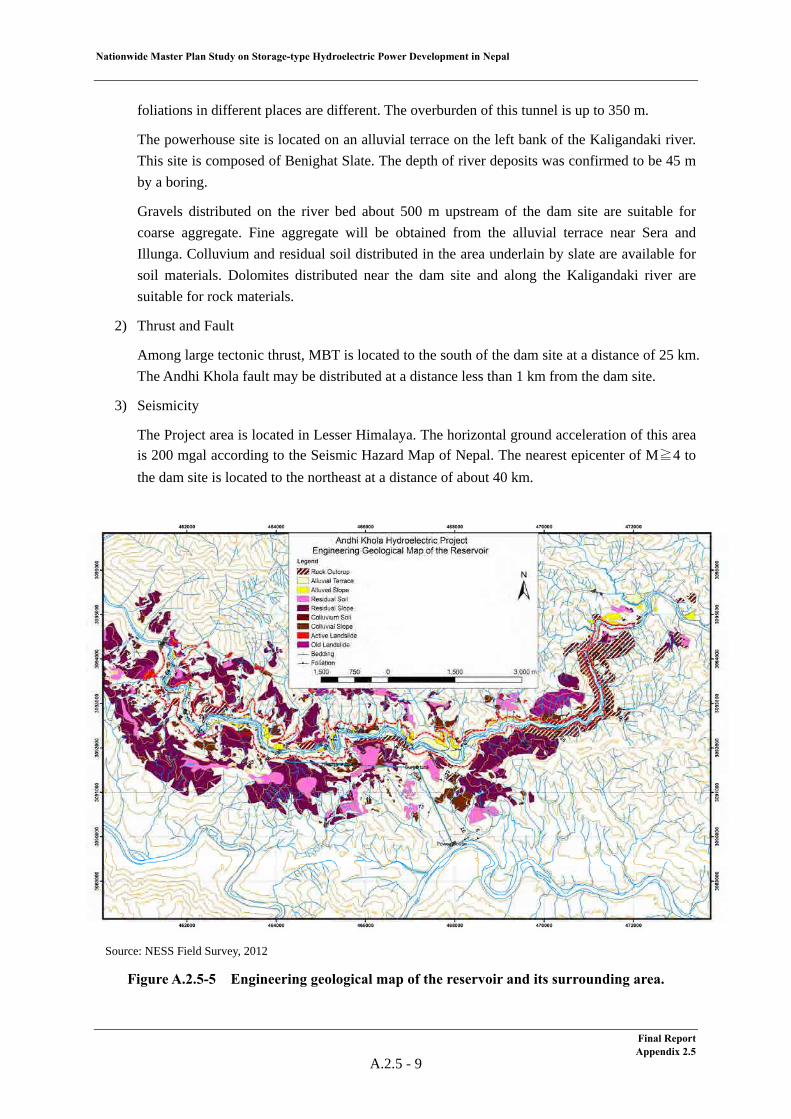
Nationwide Master Plan Study on Storage-type Hydroelectric Power Development in Nepal
Final Report Appendix 2.5
A.2.5 - 9
foliations in different places are different. The overburden of this tunnel is up to 350 m.
The powerhouse site is located on an alluvial terrace on the left bank of the Kaligandaki river. This site is composed of Benighat Slate. The depth of river deposits was confirmed to be 45 m by a boring.
Gravels distributed on the river bed about 500 m upstream of the dam site are suitable for coarse aggregate. Fine aggregate will be obtained from the alluvial terrace near Sera and Illunga. Colluvium and residual soil distributed in the area underlain by slate are available for soil materials. Dolomites distributed near the dam site and along the Kaligandaki river are suitable for rock materials.
2) Thrust and Fault
Among large tectonic thrust, MBT is located to the south of the dam site at a distance of 25 km. The Andhi Khola fault may be distributed at a distance less than 1 km from the dam site.
3) Seismicity
The Project area is located in Lesser Himalaya. The horizontal ground acceleration of this area is 200 mgal according to the Seismic Hazard Map of Nepal. The nearest epicenter of M≧4 to the dam site is located to the northeast at a distance of about 40 km.
Source: NESS Field Survey, 2012
Figure A.2.5-5 Engineering geological map of the reservoir and its surrounding area.
Nationwide Master Plan Study on Storage-type Hydroelectric Power Development in Nepal
(4) Development Plan
The Andhi Khola Project is a dam and waterway-type hydropower project. Since the study level attains feasibility study level, a set of the basic design drawings are available. The salient features of principal layout and basic layout drawings of the project are as follows:
Table A.2.5-5 Salient Features
Item Unit Andhi Khola Remarks
Reservoir
Reservoir Area at FSL km2 5.5
Total Storage Capacity MCM 336.5
Effective Storage Capacity MCM 238.7
Full Suply Level (FSL) m 675.0
Minimum Operating Level (MOL) m 626.7
Dam
Type of Dam - CFRD (Concrete Faced Rockfill Dam)
Dam Volume MCM 8.2
Total Dam Height m 157
River Bed Level at Dam Axis m 525
Spillway Type - Gated Spillway (3 Radial Gate)
Waterway & Powerhouse
Intake Type - Sloping Intake
Concrete Lined Headrace Tunnel Length
m 3,395
Tunnel Diameter m 6.5
Penstock Length m 1,350 D = 4.8m
Type of Powerhouse - Surface (Semi-underground)
Turbine Type - Vertical Francis
Installed Capacity MW 180 (3 x 60 MW)
Design Discharge m3/s 81.4
Rated Net Head m 286.3
Tail Water Level m 368.48
Tailrace Length m 85 Source: Feasibility Study on Andhi Khola Hydroelectric Project, 1998, NEA
Final Report Appendix 2.5
A.2.5 - 10
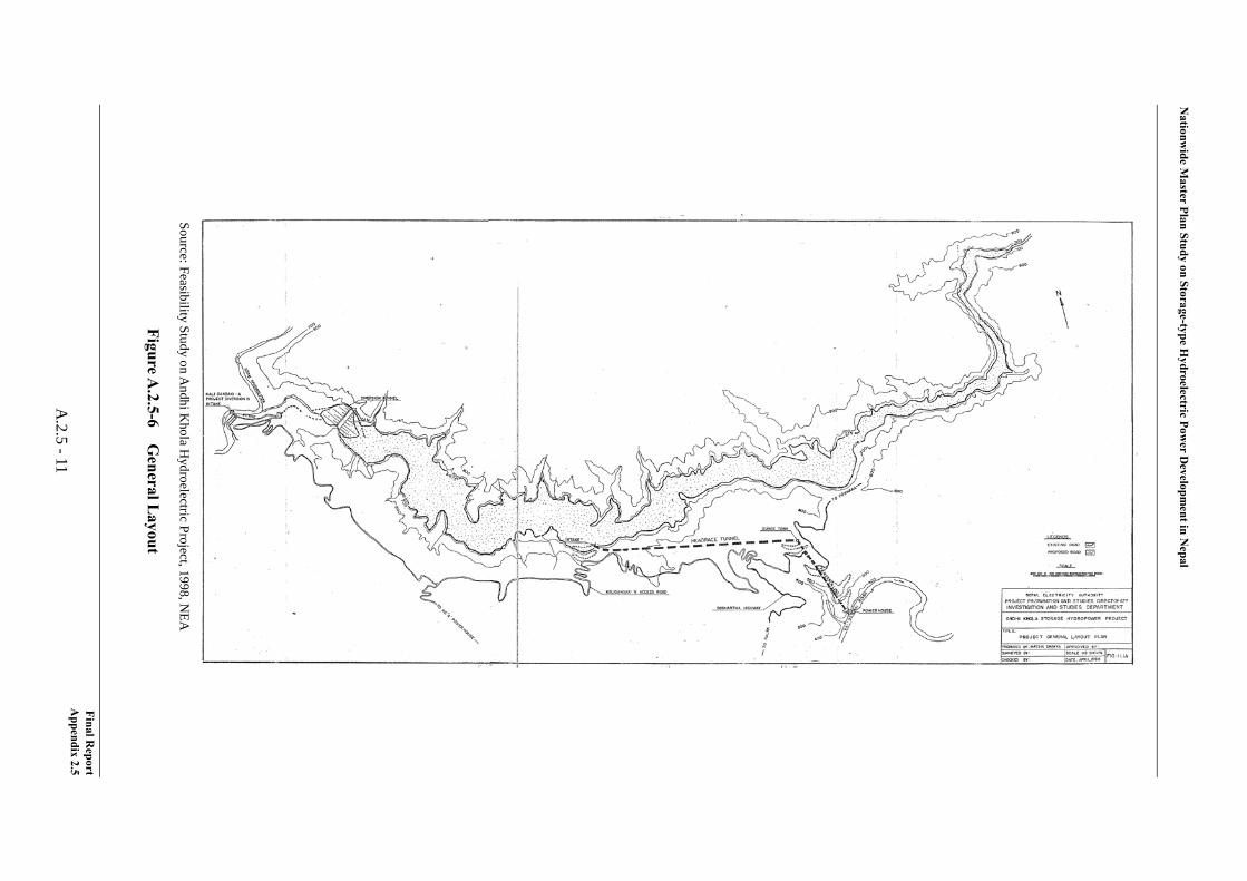
Nationw
ide Master Plan Study on Storage-type H
ydroelectric Power D
evelopment in N
epal
Source: Feasibility Study on Andhi K
hola Hydroelectric Project, 1998, N
EA
Figure A.2.5-6
General L
ayout
Final Report
Appendix 2.5
A.2.5 -11
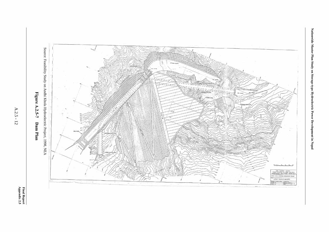
Nationw
ide Master Plan Study on Storage-type H
ydroelectric Power D
evelopment in N
epal
Source: Feasibility Study on Andhi K
hola Hydroelectric Project, 1998, N
EA
FigureA.2.5-7
Dam
Plan
Final Report
Appendix 2.5
A.2.5 -12
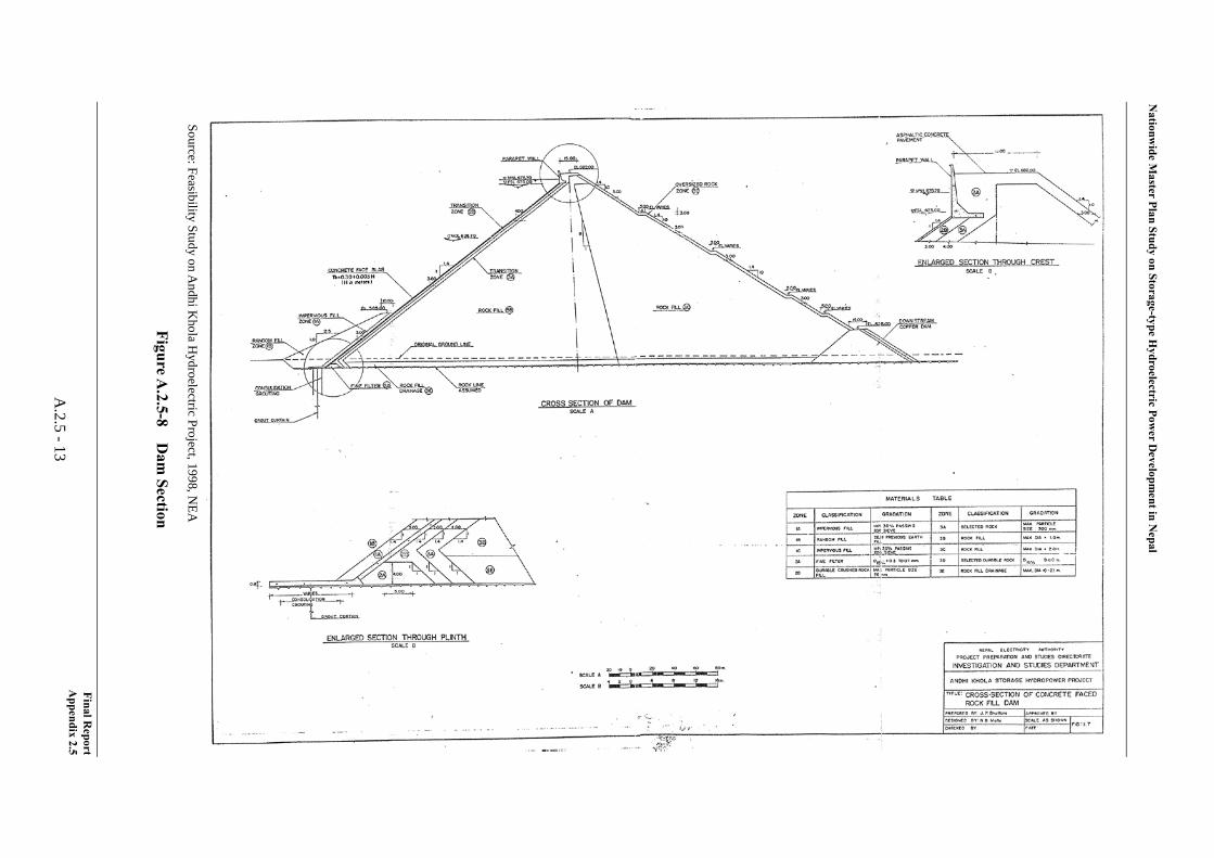
Nationw
ide Master Plan Study on Storage-type H
ydroelectric Power D
evelopment in N
epal
Source: Feasibility Study on Andhi K
hola Hydroelectric Project, 1998, N
EA
FigureA.2.5-8
Dam
Section
Final Report
Appendix 2.5
A.2.5 -13
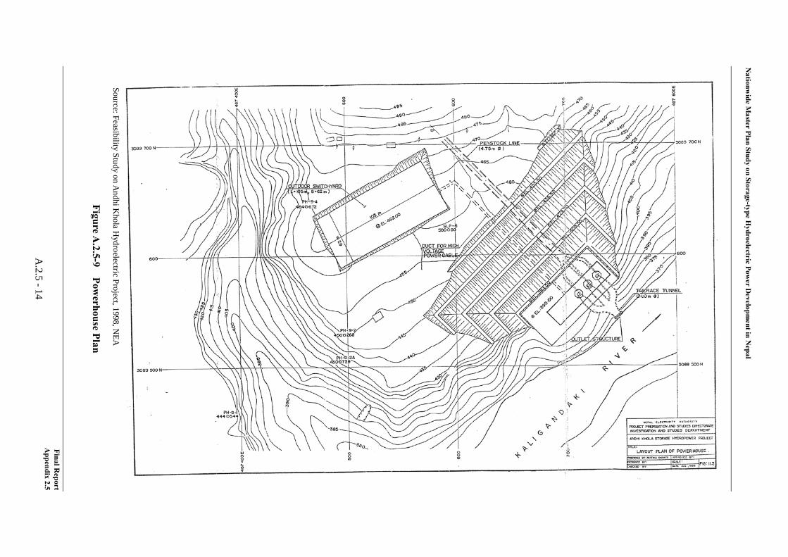
Nationw
ide Master Plan Study on Storage-type H
ydroelectric Power D
evelopment in N
epal
Source: Feasibility Study on AndhiK
hola Hydroelectric Project, 1998, N
EA
Figure A.2.5-9
Powerhouse Plan
Final Report
Appendix 2.5
A.2.5 -14
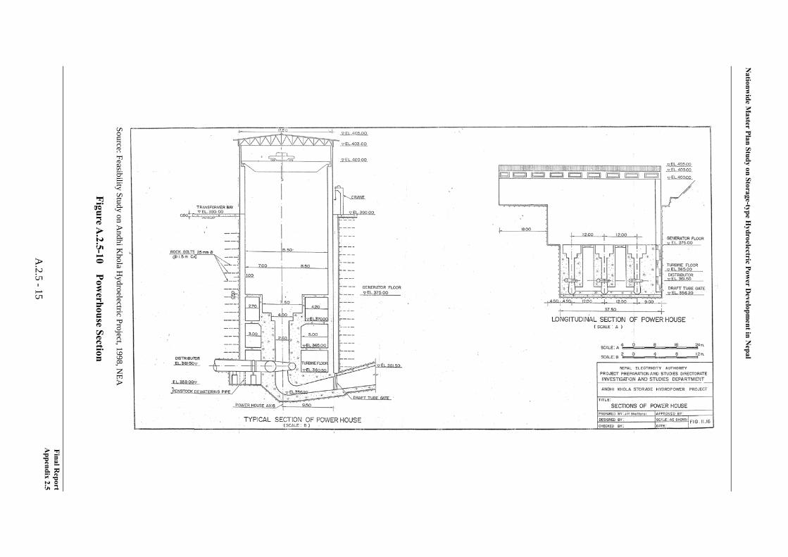
Nationw
ide Master Plan Study on Storage-type H
ydroelectric Power D
evelopment in N
epal
Source: Feasibility Study on Andhi K
hola Hydroelectric Project, 1998, N
EA
Figure A.2.5-10
Powerhouse Section
Final Report
Appendix 2.5
A.2.5 -15
Nationwide Master Plan Study on Storage-type Hydroelectric Power Development in Nepal
Further, the findings attained by the Study Team through the site reconnaissance conducted in June, 2012 in terms of dam site and powerhouse site are summarized below.
Dam Site
The dam site proposed in the FS is located at approximately 1.5 km upstream of the confluence of the Kari Gandaki river and the Andhi Khola river. The river bed elevation at dam axis is 525 m. There is the intake dam of the Kali Gandaki A Hydropower Plant (144 MW) owned by NEA at immediately downstream of the confluence. The Full Supply Level (FSL) of the peaking pond is 524 m.
A raising of the intake dam is planned at the Kali Gandaki A Hydropower Plant. Therefore, a shift of the dam site established in the FS to 2 km upstream from the original position is studied. The new dam site has originally been identified as an alternative in the FS, however, it was not adopted due mainly to geological reason. The river bed elevation at new dam axis is 30 m higher than the original site, namely, 555 m. Regarding the access to the dam site, there is a two-lanes paved road from the national highway connecting Butwal and Pokhara to the existing the Kali Gandaki A Hydropower Plant at the left bank of the Andhi Khola river. From the paved road at EL. 815 m to the Llunga village at EL. 700 m, there is a one-lane unpaved road. At the halfway of the unpaved road, there is a branch dirt road toward the dam site from the downstream side, on which tractors are going through. The unpaved road and dirt road could be the access road to the dam site with some improvement and expansion. At the moment, a topographic survey around the new dam site is being conducted by NEA. It should be careful to establish the dam axis considering some thin ridges are existing around the new dam site as the topographic features. It should be noted that geological investigations including core drillings for dam foundation, basic design of dam and waterways, construction planning and coat estimation have to be redone by moving dam site toward upstream. Further, the project optimization has to be reviewed drastically because the effective reservoir storage volume is to decrease some 30% of that of FS.
It should be recognized that it will take almost same amount of time and manpower as that for FS to redone the studies if the dam site is moved. Therefore, the moving dam site of Andhi Khola project should be examined comprehensively in consideration of the intake dam raising plan at Kali Gandaki A Hydropower Plant. Although it depends on how much the FSL of Kali Gandaki A will raise, it might be possible to deal with the raising FSL by constructing some structures such as concrete wall etc. instead of moving the dam site.
Powerhouse Site
The powerhouse is located at the left bank of the Kali Gandaki river. To change the location of powerhouse from the original location in FS toward 500 m downstream is being studied. The new powerhouse will be located at 400 m upstream of the outlet of existing Amdhikhola power plant (IPP). The coordinate is approximately 27º55’39”N, 83º40’26”E and the elevation of riverbed is approximately 380 m at the site. The average inclination of left bank from the river bed to EL.600 seems about 25 degree. There is a gentle slope farm land having lengths of 200
Final Report Appendix 2.5
A.2.5 - 16
Nationwide Master Plan Study on Storage-type Hydroelectric Power Development in Nepal
m upstream-downstream direction and 100–150 m transversal direction and inclination of 12–13 degree at EL 430–470. The area is planned to be used for switchyard in FS.
The access to the powerhouse site will relatively be easy by descending the gentle slope farm land with hairpin curves to the powerhouse site from the branch at 1.2 km upstream of the powerhouse on the national highway connecting Butwal and Pokhara. However, a bypass road will be required for the Ridi town if equipment and materials for construction are transported through the Ridi town.
Others
Regarding the existing Andhikhola Hydropower Plant (5.1 MW) owned and operated by Butwal Power Company, a comparison study was conducted in the FS. In the study, two cases were compared. One is to abolish with full compensation and the other was to continue to operate with some renovation by implementation of the Andhi Khola Project. As a result of the study, it was concluded that to operate with some renovation will be more economical. At the moment, the power plant is planning to expand the install capacity to 9 MW, and conducting a construction works to raise the intake dam. Regarding the powerhouse part, the renovation works will be commenced in 2012 the generation will be resumed in 2013.
Furthermore, as for the Andhi Khola Project, there is information that a Korean company offered to develop the project to the NEA though it has yet to reply.
(5) Electrical/Mechanical Equipment and Transmission Line
1) General
Rated effective head, power discharge and installed capacity of the Andhi Khola Project are as follows;
Rated Effective Head : 286.30 m Rated Power Discharge : 81.40 m3/s Installed Capacity : 180 MW
The HD Wiz (developed by J-POWER, based on existing hydropower plant data around world) has been used for reviewing design of electrical/mechanical equipment taking above information into consideration. Turbine efficiency and generator efficiency have been improved in recent years and installed capacity exceeded above-mentioned 180 MW consequently.
2) Unit Capacity and Number of Unit
Generally, for the turbine-generator, a large unit capacity is said to be more economical merits of scale. However, optimum unit capacity of the turbine-generator is determined in consideration of influence to the power system, development timing and transportation restriction.
In this project, all electrical and mechanical equipment will be transporting from foreign
Final Report Appendix 2.5
A.2.5 - 17
Nationwide Master Plan Study on Storage-type Hydroelectric Power Development in Nepal
countries via Indian national road and un-maintained Nepalese national road to the project site. Therefore maximum unit capacity shall be set as around 100 MW and number of 3 units plan has been adopted for the project.
3) Turbine
a) Turbine Output
Rated turbine output at rated effective head of 286.30m and rated power discharge of 27.13 m3/s per unit can be calculated as follow;
Pt = 9.8 × Hn × Qt × ηt = 9.8 × 286.30 × 27.13 × 0.919 ≈ 69,900 kW where Pt : Rated turbine output per unit (kW) Hn : Rated effective head (m) Qt : Rated power discharge per unit (m3/s) ηt : Turbine efficiency
b) Type of Turbine
Generally, type of turbine can be determined by close relation between effective head and turbine output. Vertical shaft Francis type turbine can be selected taking rated effective head and turbine output into consideration.
c) Runner Material
Stainless steel anti-corrosion type such as 13 chrome high nickels stainless steel is recommended to be applied for the runner material. Surface of runner and wear ring shall be coated (hard or soft) in case of water quality. Detailed coating method shall be specified in the detailed design stage.
d) Installed Capacity
Installed capacity can be calculated from aforementioned turbine output per unit as follow;
69,900 kW × 3 = 209,700 kW
Review of energy calculation is conducted by using above installed capacity.
4) Generator
A three phase alternating current synchronous generator with vertical shaft rated capacity of 75,800 kVA and power factor of 90% lag are selected.
a) Generator Capacity
Rated generator capacity can be calculated from rated turbine output, power factor and generator efficiency as follows;
Final Report Appendix 2.5
A.2.5 - 18
Nationwide Master Plan Study on Storage-type Hydroelectric Power Development in Nepal
Pg = Pt × ηg / p.f (kVA) = 69,900 × 0.977 / 0.90 ≈ 75,800 kVA where Pg : Rated generator capacity (kVA) Pt : Rated turbine output (kW) ηg : Generator efficiency p.f : Power factor, lag
As the results of above calculation, rated generator capacity is 75,800 kVA.
5) Transmission Line
Regarding designing of the transmission line, transmission line shall be connected to the closest substation based on 400 kV Transmission Line Power Development Plan by the NEA. And also thermal capacity and maximum surface potential gradient have been taken into consideration for designing of the transmission line and following specifications have been adopted. As for the transmission line length, the direct length from project area to closest substation was measured from map. Therefore, some allowance has been taken into consideration.
Connected Substation : Hetauda Substation Transmission Line Voltage : 220 kV Length of Transmission Line : 49 km Conductor Type : Bison × 1, 2 circuits
Final Report Appendix 2.5
A.2.5 - 19