Embed Size (px)
Citation preview

-4
:
NATIONALADVISORY COMMITTEEFOR AERONAUTICS
TECHNICAL NOTE 2756
NOISE FROM INTERMITTENT JET ENGINES AND STEADY-FLOW
JET ENGINES WITH ROUGH BURNING
By Leslie W. Lassiter
Langley Aeronautical LaboratoryLangley Field, Va.
Washington
August 1952
AFMDCv
o00-

lG
*
TECH LIBRARY KAFB, NM
Illlllllllllllllllllllllil!llllllll0Clb58?ll
NATIONAL ADVISORY COMMITTEE FOR AERONAUTICS
TECHNICAL NOTE 2756
*
NOISE FROM INTERMITTENT JZT ENGINES AND STUDY-FLOW
JET ENGINES WITH ROUGH BURNING
By Leslie W. Lassiter
suMMARY
Sound measurements were made on a pulsejet and a sulsonic rsmjetof the types used for helicopter rotor drive and on a turbojet withafterburner. The pulsejet was found to produce a discrete-frequencyspectrum having a single predominant component corres~onding to theengine firing frequency. The angular distribution was slightly direc-tional, with the largest sound pressures occurring to the rear of theengine and near its axis. It was found that an estimate of the noiselevel from a pulsejet couldbe made by application of resonant-tubetheory, if certain of the average flow parameters of the engine areknown or can be reasonably approximated.
The small subsonic rsmjet and the turbo,jetwith afterburner wereboth found to produce discrete-frequencyspectrums, however, contrasted with thatcontained several harmonic components ofthat of the fundamental.
noise spectrums. Theirof the pulsejet in that theymagnitude comparable with
INTRODUCTION
The usefulness of intermittent jet engines may be greatly limitedbecause of the intense noise associated with their operation. Theyare otherwise very attractive for many applications, because of theirsimplicity of operation, the small smount of auxiliary equipment neces-sary, and the high pay loads obtainable as a result of their largethrust-weight ratio. These features make them particularly attractiveas a source of rotor power for helicopters. —
The shutter type of pulsejet is the most common form of intermittentengines and is designed so that its jet issues from the nozzle in periodicbursts rather than in a continuous stresm. In operation of this type ofengine, air is drawn into the tube through the flapper type of valves atthe forward end and through the tail-pipe orifice and is mixed with fuel
2 NACATN 2756
in the combustion chsmber. The subsequent combustion raises the chsmberpressure sufficiently to force the valves closed and thereby permits theexhaust gases to escape only through the exit nozzle in order to producethrust. The cycle is repeated at a particular frequency, correspondingto the resonant frequency of the tube-chambe~-combination.
Very few systematic studies have been made of the noise from pulse-jet engines; most of the data currently available were obtained atisolated points in the sound field around partially enclosed engine testcells. These data, however, have indicated that the noise generated bya pulsejet consists principally of discrete-frequency components whichcorrespond to multiples of the engine firing frequency. During rough-burning conditions some types of steady-flaw jet engines, such as ramjetsand turbojets with afterburners, may also generate noise of a discrete-frequency nature, somewhat similar to that ofia pulsejet.
This paper presents noise spectrums and spatial distributions forthe pulsejet and ranjet and gives a noise sp&ctrum of a turbojetiwithafterburner. Experimental results for the pul.sejetare compared withcalculations by an analysis based on the radiation characteristics ofa resonant pipe. —.
SYMBOLS
E radiated sound energy per unit tfie, ergs/see
u angular sound frequency, 2nf, radians/see
f sound frequency, cps .
r jet-exit radius, cm
s jet-exit area, sq cm
P density of smbient air, g/cu cm
P’ average density of air at jet exit, g/cu cm
P“ density of exit gas at temperature t“, g/cu cm
Pi density of intake air at temperature ti, g/cu cm
t ambient temperature, OR
tc“ peak combustion-chamber temperature, %
II

NAcA TN 2756 3
~11
t~
a
a’
a“
ai
I
u
u’
P
F
P
pc t!
R
h
7
H
F/A
Cp
CT
k
*
z
D
peak temperature at jet exit, oR
minimum temperature at Jet exit during intake, OR
speed of sound in ambient air, cm/sec
average speed of sound at jet exit, cm/sec
sound
sound
sound
speed in exit gas at temperature t“y cm/8ec
speed at temperature ti, cm/sec
intensity, ergs/sec/sq cm
root-mean-square value of alternating velocity, cm/sec
average gas velocity at jet exit, cm/sec
root-mean-square value of sound pressure, dynes/sq cm
(db =)
20 @310 *●
over-all sound pressure, dynes/sq cm
atmospheric pressure, dynes/sq cm
peak combustion-chamber pressure, dynes/sq cm
universal gas constant, ergs/°C/mol
internal energy of air in combustion chsmber, BTU
combustion efficiency, percent
higher heating value of fuel
fuel-air ratio
specific heat at constant pressure
specific heat at constant volume
ratio of specific heats, cp/cv
azimuth angle (referred to Oo ondeg
jet axis to rear of jet),
distance from point of measurement to jet exit, cm
jet-exit dismeter, cm

4 NACA TN 2756..— — —
Subscripts:
1 relating
z value at
i.—
to fundamental Fourier component
distance Z from jet exit
APPARATUS AND METHODS
Sound measurements were made on a pulseJetof the types (fig. 1) used for helicopter rotcm
and a subsonic ramjet-drive and on a turbojet
with afterburner. Data were obtained at the 80- and 100-percent-rated-thrust conditions for the pulsejet and at the 100-percent-rated-thrustcondition for the turbojet with afterburner. Because of fuel-pumplimitations, the 100-percent-rated-thrustcondition could not be main-tained for the rsmjet; therefore, all measur~ents on the ramjet weremade at the 80-percent-rated-thrustcondition.
Two test locations were utilized to obtain the data from the pulse-jet. The 80-percent-rated-thrustmeasurement~ were made with the unitoperating on a thrust stand in the vicinity of the Langley helicoptertest tower, as shown schematically in figure 2(a). The 100-percent-rated-thrust data were obtained near the Langley 16-foot transonictunnel, as shown schematically in figure 2(b)., All data from the ram-jet were obtained at the latter location in order that rsm pressuremight be obtained from the variable-speed blower and converging nozzleindicated in the figure. This equipment was capable of delivering airat a maximum velocity of 655 feet per second to the ramjet inlet diffuser.It was used with the pulsejet only for starting; once ignited, the enginewas allowed to operate statically.
Data from the turbojet afterburner were obtained with the unitfunctioning in an operational aircraft, which was secured to a concretebase for the tests. No large reflecting surfaces other than the groundwere within a radius of approximately 1,000 feet. The sound measurementswere made at ground level 5Q feet from the jet exit.
1 feet aboveThe pulsejet and ramjet sound measurements were made 2=
ground level at a distance of 10 feet.f’romthe jet exit. “Data wereobtained at intervals of 1>0 in azimuth angle ~ from Oo to W“. Atthe 80-percent-rated-thrust condition for the pulsejet, this range wasextended to 1200.
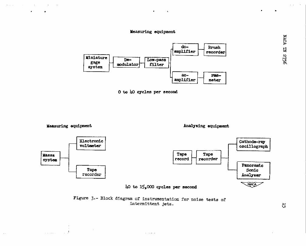
Data were obtained over the frequency range of O to 15,000 cyclesper second by means of the two measuring systems shown schematically infigure ~. A Massa Laboratories Model GA-1OO2 sound-pressuremeasurement-
.-
...
—
.-
P

NACA TN 2756
system was employed in the range of @ to 15,000 cyclesan NACA miniature electrical pressure gage and low-yass
5
per second andfilter unit
were used in the range of O to hO cycles per second. Output of theMassa system was recorded on a Type PT-6 Magnecorder tape recorder toprovide a pezmanent record for later analysis. Similarly, the outputof the miniature gage system was recorded on a Brush pen recorder.Total sound-pressure.levelsin each frequency band were obtained fromelectronic voltmeter readings at the output of each measuring system.
Frequency spectrums for each unit at the various azimuth angleswere obtained by playback of the recordings into a Panoramic Sonic Ana-lyzer, which presents graphically on its viewing screen a plot of inten-sity against frequency for the frequency range of h to 20,000 cyclesper second. The magnecorder records were played directly into theanalyzer, as indicated in the lower right-hand portion of figure 3.Playback of the tape recordings was also made into a conventionalcathode-ray oscillograph to obtain total-pressure wave forms of thenoise.
ANALYSIS
Since the pulsejet operating cycle is an acoustic-resonancephenomenon, it is of interest to compare the experimental noise datawith results of an approximate analysis based on the assumption thatpulsejet noise-radiation properties are comparable with those of aresonant pipe. For simplification of the analytical procedure, onlythe fundamental Fourier component is considered.
The sound energy per unit time E radiated from a tube subject tosinusoidal excitation has been derived from references 1 and 2 as
()~2E =~Su12p’a’ —a
(1)
where the primed quantities are average values at the tube exit when themedium inside the tube is at a different temperature from that of thesmbient air. This energy is dispersed in accordance with the radiationcharacteristic of the tube, which, in keeping with the pipe analogy, isassumed to be identical in all directions when the wave length of soundis large relative to the tube dismeter. Hence the sound power per unitarea, or intensity, at the distance Z is obtained by dividing equa-tion (1) by the area of a sphere of radius Z. Thus,

6 NACA TN 2756.—
.
and since
(2)
the sound pressure is given as
u)su~ ppt~t l/2()Plz=— —21tZ a (3)
In order to calculate the magnitude of the fundamental sound pressureat distance Z the par&meters pl, al, and U1 must be evaluated. The
following approximate thermodynamic analysis, based on the treatment of – –—reference 3 and oiithe assumption of a constant-volume combustion process,may be used for that purpose.
.
If the work done by the intake ram is neglected, the initial condi-tions of density, temperature, and pressure in the pulsejet--combustionchamber are essentially the ssme as those in the ambient medium. Com- .
bustion of the fuel produces an increase in the internal energy of-theair mass of magnitude
This increase leadsto the new value
Ah= @ f
to an elevation of’the combustion-chamber temperature
t~’t = t+A&Cl/
and results in an increased presswe of
tc”pc t, =P—
t
If this pressure is greater than 1.89P,choking occurs at the tube exit and the peak
as is usually the case,pressure at that point is
NAC!ATIi 2756 7
limited to 0.528PC”. The corresponding peak temperature t“ at thetube exit is then
k-1
t“ = tc”(o.528) k
and results.in a sound speed at that temperature of
a“=(0”577’2where the density p“ is expressed as
O.528PC”P“ = —
Rt”
Hence, as shown in the accompanying diagram, the peak exit velocityis a“.
On the intake half-cycle, the peak velocity approaches a limit which isthe speed of sound under the conditions existing after an adiabaticexpansion from atmospheric pressure to a pressure of o.528P. By assuming
8 NACATN 2756—
.
that the engine operates near this limit on intake, the negative peakvelocity may be approximated by —
&
ai _o.5@8pr
pi .-
—
where
--%-O. 28P
Pi=ot.
Thus the assumption that the velocity wave form is approximatedbya sine wave alternating about some average value requires that theseamplitudes, positive and negative, define the double amplitude of thesine wave. Its root-mean-squarevalue is then
an + aiul=—
2P
The average density p’ and sound speedequation (3) are obtained from
Pi - P“P’=P-~
and
a’ to be substituted into “
+
—
—
.—
a’ = a+-31
The sound yressure calculated by substituting these values intoequation (3) is that in a free field. When the engine is operated
near ground level, the pressures may be expected to approach a valuetwice that calculated, since conditions then approximate a sourceradiating into a semi-infinitemedium.
——
RESULTS AND DISCUSSION
PulseJet
Over-all angular distribution.- The angular distribution of over-allsound pressure from the pulsejet is shown i.n.thepolar diagram of fig-ure 4 for the &l- and 100-percent-rated-thrustconditions. The curves
.
e
.

2G NACATN 2756. 9
m
shown were plotted from the data obtained only in the range of @ to15,000 cycles per second, since pressures in the range of O to ~ cycles
● per second were of the order of 50 decibels below that of the pulsejetfundamental and were masked by the higher-frequency noise which camethrough the low-pass filter. Since the 80- and 100-percent-rated-thrustdata were obtained at different locations, an attempt has been made toadjust the latter on the basis of a correction factor indicated by acomparison of a set of check data at an azimuth angle of 300 and100-percent-rated-thrustcondition from both locations. The curvesindicate that pulsejet noise has a distribution which is only slightlydirectional in the region rearward of the Jet exit for both the 80-and 100-percent-rated-thrustconditions but which drops off ratherquickly at angles near 90°. The increase in thrust results in a mag-nitude change in the over-all level of approximately 3 to 6 decibelsfor the azimuth angles measured. The greatest increases occur at smallazimuth angles, where the level is increased from approximately 138.5to 144 decibels.
Frequency spectrums.- The frequency content of pulsejet noise isillustrated by the spectrums and wave forms shuwn in figure 5. The graphsat the left of the figure are panoramic frequency analyses at threeazimuth angles, and the wave forms at the right-hand side are the corre-sponding records of total pressure against time, shown above a referencesine wave of 100 cycles per second. The unequal spacing of intensitygrid lines in the spectrum plots is a characteristic of the design ofthe analyzer, which ordinarily indicates in decibels above and belowan arbitrary reference level coinciding with midscale deflection. Forthe present tests, the analyzer was calibrated to indicate absolute valuesof sound pressure. The spectrums indicate that, at all azimuth angles,the over-all noise is composed chiefly of a single tone of approximately100 cycles per second. Several harmonics of this frequency are presentalso, but their magnitudes relative to that of the fundamental are suchthat they do not contribute much to the over-all level. This fact canalso be seen from the wave forms, since they do not generally departgreatly from sinusoids. The predominant noise frequency of 100 cyclesper second corresponds to the firing frequency of the unit, which isdetermined by the resonant frequency of the configuration and is hencea function of tube length, combustion-chaber vol~e, and operating
temperature.
A comparison of the measured fundamental distribution with thatcalculated from equation (3) on the assumption of sinusoidal operationis shown in figure 6. Values of the parameters used in the computationare as follows:
F-= 0.0717A
Yj=0.20
.—
r = 7.6 cm t = 54.0° R
(D= 628 radians/see

10 NACATN 27.56.- ——
The two curves indicate good-agreement at azimuth angles up to approxi-mately 450; at larger angles the measured values are lower than thosecalculated from the simple-resonant-tube theory. It appears thatrefinement of the present simplified analysis is necessary in order toresolve this distribution discrepancy. The observed tendency for theanalysis to overestimate the pressure levels at reduced engine thrustis considered to be further evidence that some refinement is necessary.
Noise reduction.- The predominance of’the fundamental component ofpulsejet-noise and the fact that-its wave length is large relative tothe engine exit diameter suggest thatmuti-of-phase operation of dual-engine installations in close proximity might prove beneficial inreducing the noise levels. Several proposed means of obtaining out-of-phase operation of dual units have been illustrated in a paper (notgenerally available) byK. Staiger and W. I. E. Kamm, which deals withthe operating characteristics of pul.sejetengines.
Steady-Flow Jet Engines With Rough Burning
When either internal appurtenances csran unsteady-flow state leadto a condition of rough burning, certain steady-flow jet engines suchas ramjets and some turbojet afterburners generate noise which, in somerespects, is similar to that from a pulsejet. Although these enginesdo not, in general, function in an intermittent manner, they do producea discrete-frequency sp~c!trumrather than the random spectrum usuallyassociated with steady-flow jet engines (ref. 4). Data from the subson~cramjet and a turbojet with afterburner are”therefore included in thepresent paper.
Over-all distribution for small rsm~et.- The angular distributionsof over-all noise for the small rsmjet in the frequency ranges of O to@ cycles per second and @ to 15,000 cycles per-second are illustratedin figure 7 for the &)-percent-rated-thrustcondition at a ram velocityof 655 feet per.second. Like that of the pulsejet, ramjet noise appearsto be slightly directional rearward of the engine for the frequency rangeof @ to 15,000 cycles per second. The maximum sound pressures occurnear 15° azimuth; pressures at the 90° azimuth are somewhat less thanthose measured at smaller angles. A rather sharp directional patternis associated with the noise in the range of O to @ cycles per secondwhich produces a lobe in the axial direction rearward of the engine.
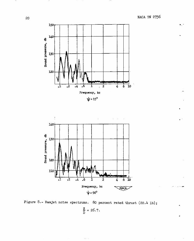
Frequency spectrum of small rsmjet,- Figure 8 illustrates the typeof spectrums obtained at two different azimuth angles from measurementson the subsonic ramjet at 80 percent rated thrust. Z%e spectrums indicatethat the rwnjet noise contains several discrete=frequency components---near the low end of the frequency scale. The magnitudes of these
.
—
—
NACATIf 2756 11....
components were found to be of a similar order at both azimuth angles,as was true for the pulsejet noise. .Inaddition to these components,it is to be expected that the ram blower will contribute a random noiseof the type usually associated with continuous jets; however, a seriesof measurements taken with the engine in position, but inoperative,indicates that, in the frequency range of the discrete components, therandom noise of the blower is of the order of 25 decibels lower thanthe levels of the periodic components.
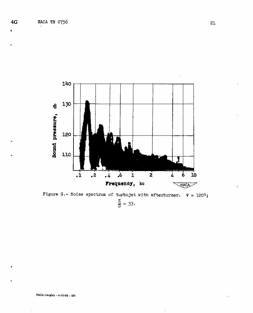
Turbojet with afterburner.- In some cases the afterburner methodof turbojet thrust augmentation produces a periodic noise somewhat likethat of the subsonic rsmjet. An illustration of afterburner noise ofthis type is given in figure 9, which presents the frequency spectrumof noise from a turbojet engine during afterburner operation. Thefigure indicates that several predominant discrete-frequency componentsare present in addition to the random noise. These discrete componentsappear to bear a harmonic relation to each other, as was true for boththe ramjet and pulsejet. Hence, under certain conditions of roughburning, the nature of afterburner noise during static operation maybe somewhat like that of a subsonic ramjet and a pulsejet.
CONCLUSIONS
Sound measurements on a pulsejet, a subsonic ramjet, smd a turbo-jet with afterburner indicated the following conclusions:
1. PulseJet noise is composed principally of a few discrete-frequencycomponents which bear a harmonic relation to each other. The fundamentalfrequency corresponds to the engine firing frequency and is generally ofgreater amplitude than its harmonics.
2. The spatial distribution of the pulsejet sound field is slightlydirectional in the region rearward of the jet exit and appears to boyoff rather sharply at angles near no.
3. Comparison of experimental and calculated values of fundamentalsound pressure of the pulsejet indicate good agreement at azimuth anglesup to approximately 450; at larger angles the measured values are lowerthan those calculated from simple resonant-tube theory.
4. Under conditions of rough burning, ramjets and some turbojetafterburner units may generate noise spectrums which contain severaldiscrete-frequency components near the low end of the frequency scale.
a
Langley Aeronautical LaboratoryNational Advisory Committee for Aeronautics
e Lamgley Field, Vs., June 2, 1952

12 NACA TN 2756
.
REFERENCES *
1. Richardson, E. G.: Sound.. Edward Arnold &Co. (London), Fourth cd.,1947, Pp. 239-2@.
2. Stewart, George Walter, and Lindsay, Robert Bruce: Acoustics. D. VanNostrand Co., Inc., 1930, p. 130. —
3. Katz, Israel: Principles of Aircraft Propulsion Machinery. PitmanPub. Corp., 1949, pp. 111-119. .— — .—
4. Eldredge,”Donald H., Jr., and~arrack, Horace O.: Jet Engine SoundSpectra. AF TR No. 5827, ATI 57639, Air Materiel Com@nd, U. S.Air For.ce,June 1949.

, NACATN 275613
m
.
1
Air fhw Combustion&amber Tail*P
valves\
(a) Pulsejet.
Air fh*
Fuelnozzles
(b) Subsonic ramjet.
Figure l.- Schematic drawings of typical pulsejet and subsonic ramjetused for helicopter rotor drive.
a
b

.—NACA TN 2756
●
/1.5ft
Testhouse .—
— 25rt~ r Pulsejet
--r-..w \1 --’I\ Cq
“’.,* ‘~. +.. A
(a) Vicinity of Langley helicopter test tower. .,.
30 ft high
ft50
LILn-130 ft
716-foottunnd—
-.7 —.
(b) Vicinity of Langley 16-foot transonic tunnel.
Figure 2.- Test areas for pulsejet and ramjet-noise measurement-s.
‘
Measuring equipment
O to 40 cycles per second
Measuring equiplent -%bz equbmut
. .
&‘Kszl
Cathode-ray
Oscillograph
Tape
record
Panoramic
J%%
@ to 15,000 cycles per second
Figure 3.- Block diagram of instrumentation for noise tests of
intmnittent Jets. G

NACA TN 2756. . ..-L..
.
.
-J20C
p, db
120 130 Uo
100 percentrated thrust
/ \ \.-.. n -. n ——n .-nJJJ5” 90” 75” A
Figure 4.- Angular distributionz5
of over-all sound pressure from pulsejet.
= 20.
.
.
.,. . -+

173G
s
.
I
— .. —---P &.— -e. - -,=- .:. s
-L
.-L .4 ,
—
—
—
—
It!—2
—
—
—
—
m—
Frequency, kc
Figure 5.- PulseJet noise spectrums and
thrust (72 lb);
—
—
—
m-
i& 1kl/ Py49 ‘“
..... ..“-. .1’.-.1-.
,.
I
91Y
wave forms. 80 percent rated
z-= 20.D
-.

18 NACA TN 2756
Uo 1.30 w 150
~ lZxpr5-mer----- Theory
d“.-m-. -&e
90° 750 45° K@J$7
Figure 6.- Angular
60°Azimuth angle, ~
distribution of pulsejet
rated thrust (90 lb); ~
fundamental. 100
= 20.
0°
15°
)0°
.
.
-
percent —
.
.

NACA TN 2756 19
9
:, db
100 llo 120 130
n —-n . -mw 75”
Azimuth angle, ~
Figure 7.- Angular distribution of
with rough burning. 80 percent
over-all sound pressure
rated thrust (22.4 lb);
from rsmjet
Z = 26.7.D
.
.
20 NACA TN 2756
—
—
—
—
—
—
—
—
—
—
m—
—
—
—
—
Bu—
—
—
—
—
w—
Frequency,kc
@~”
0“
.—
Figure 8.- Rsmjet noise spectrums.
z--=D
80 percent rated thrust (22.4 lb);
26.7.
.
.
4G NACA TN 2756
●
✎
—
—
—
.1 .2 .4 ●6 1
hequenoy,
Figure 9.- Noise spectrum of turbojet
z- = 33.D
2
.
6 10
kc-
with afterburner. ~. ~oo;
21
NACA-Langley -4-15-54-100