Embed Size (px)
Citation preview

1
Inside the pulsejet engineReport 1.0
Written byFredrik Westberg
This report would not exist without Dave Brill who inspired me from the begining, thanks for all help.
Also a great thanks to those who have contributedwith all kinds of information.
This report is a private study on the pulsejet engine.
You can contact me by e-mail,“[email protected]”
My homepage address.“http://www.geocities.com/Area51/Rampart/9722/welcome.htm”.
This document is free available on my homepage.
2
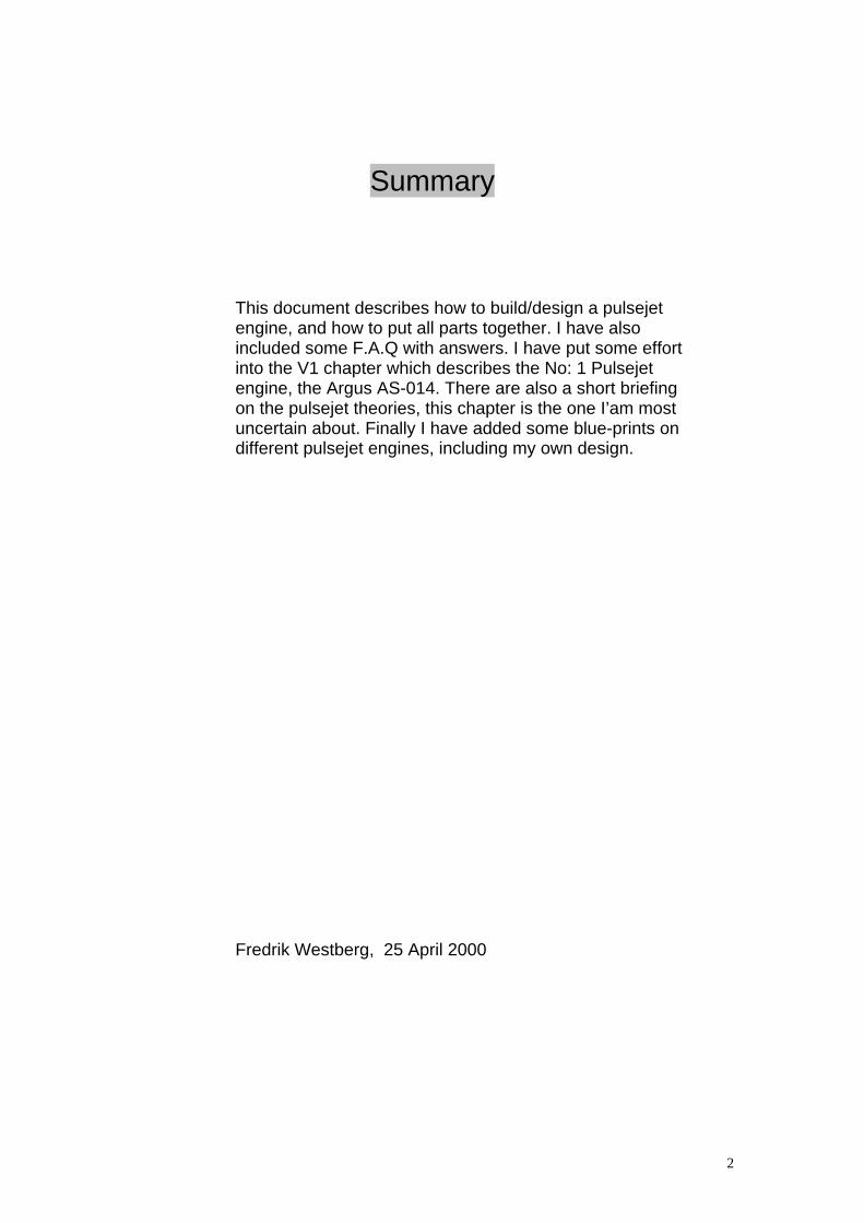
Summary
This document describes how to build/design a pulsejetengine, and how to put all parts together. I have alsoincluded some F.A.Q with answers. I have put some effortinto the V1 chapter which describes the No: 1 Pulsejetengine, the Argus AS-014. There are also a short briefingon the pulsejet theories, this chapter is the one I’am mostuncertain about. Finally I have added some blue-prints ondifferent pulsejet engines, including my own design.
Fredrik Westberg, 25 April 2000
3
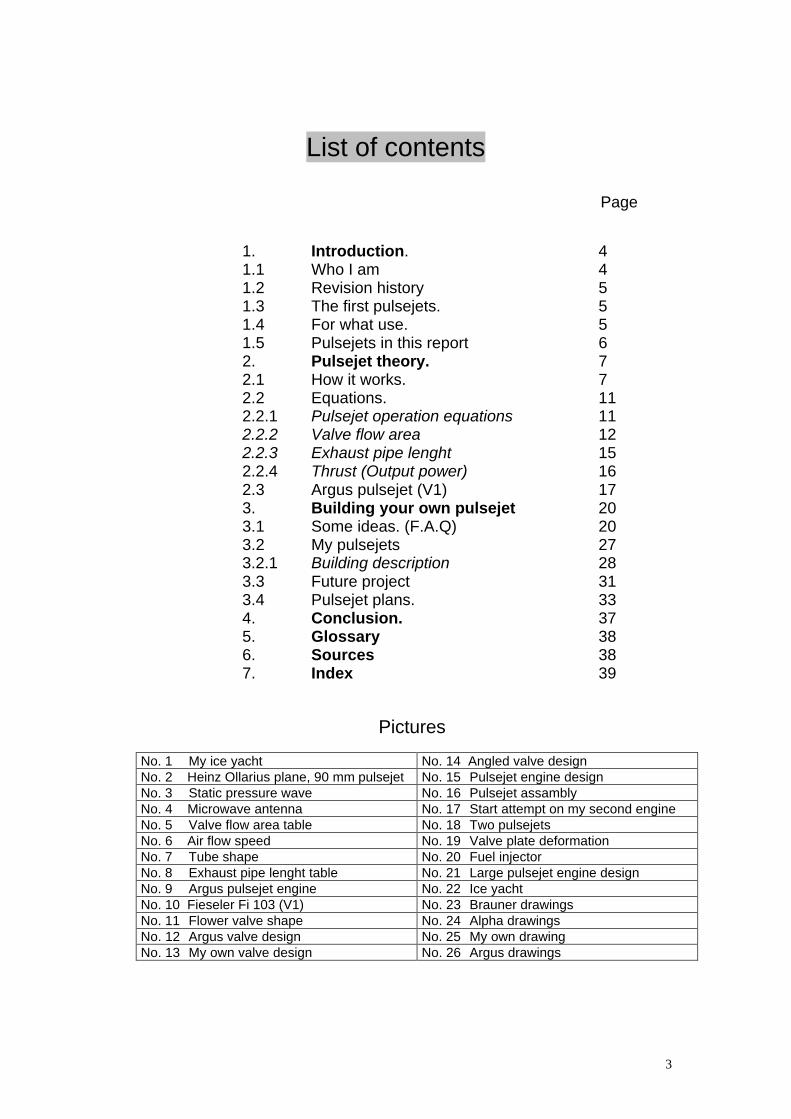
List of contents
Page
1. Introduction. 41.1 Who I am 41.2 Revision history 51.3 The first pulsejets. 51.4 For what use. 51.5 Pulsejets in this report 62. Pulsejet theory. 72.1 How it works. 72.2 Equations. 112.2.1 Pulsejet operation equations 112.2.2 Valve flow area 122.2.3 Exhaust pipe lenght 152.2.4 Thrust (Output power) 162.3 Argus pulsejet (V1) 173. Building your own pulsejet 203.1 Some ideas. (F.A.Q) 203.2 My pulsejets 273.2.1 Building description 283.3 Future project 313.4 Pulsejet plans. 334. Conclusion. 375. Glossary 386. Sources 387. Index 39
Pictures
No. 1 My ice yacht No. 14 Angled valve designNo. 2 Heinz Ollarius plane, 90 mm pulsejet No. 15 Pulsejet engine designNo. 3 Static pressure wave No. 16 Pulsejet assamblyNo. 4 Microwave antenna No. 17 Start attempt on my second engineNo. 5 Valve flow area table No. 18 Two pulsejetsNo. 6 Air flow speed No. 19 Valve plate deformationNo. 7 Tube shape No. 20 Fuel injectorNo. 8 Exhaust pipe lenght table No. 21 Large pulsejet engine designNo. 9 Argus pulsejet engine No. 22 Ice yachtNo. 10 Fieseler Fi 103 (V1) No. 23 Brauner drawingsNo. 11 Flower valve shape No. 24 Alpha drawingsNo. 12 Argus valve design No. 25 My own drawingNo. 13 My own valve design No. 26 Argus drawings
4
1. Introduction
1.1 Who I am
My name is Fredrik Westberg, and I’m born in April 1973, in Sweden. I am(right now) a bachelor or engineer in computer and electronic science, but myinterest’s lies more into the mechanic science area, like pulsejet engines andother physical things. Anyway, I do have an ordinary jobb, right now as a testengineer. My job is to make test equipment for printed circuit boards and forlarge systems. My employer is Solectron.
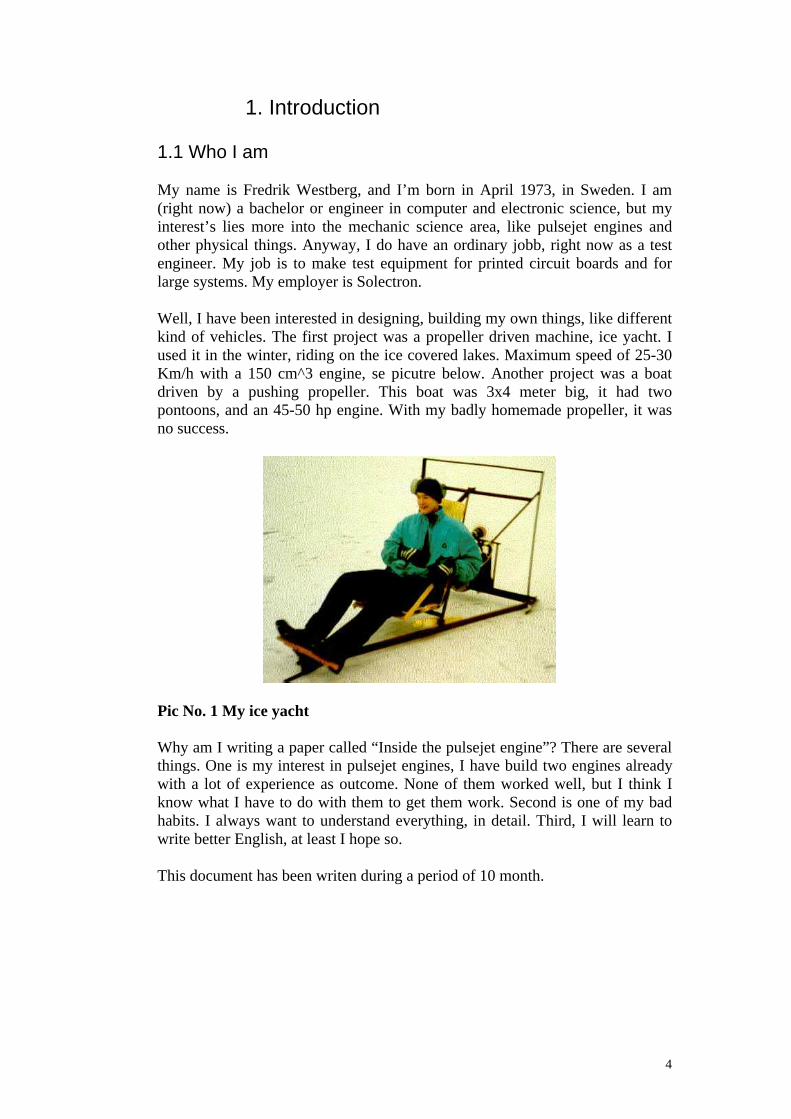
Well, I have been interested in designing, building my own things, like differentkind of vehicles. The first project was a propeller driven machine, ice yacht. Iused it in the winter, riding on the ice covered lakes. Maximum speed of 25-30Km/h with a 150 cm^3 engine, se picutre below. Another project was a boatdriven by a pushing propeller. This boat was 3x4 meter big, it had twopontoons, and an 45-50 hp engine. With my badly homemade propeller, it wasno success.
Pic No. 1 My ice yacht
Why am I writing a paper called “Inside the pulsejet engine”? There are severalthings. One is my interest in pulsejet engines, I have build two engines alreadywith a lot of experience as outcome. None of them worked well, but I think Iknow what I have to do with them to get them work. Second is one of my badhabits. I always want to understand everything, in detail. Third, I will learn towrite better English, at least I hope so.
This document has been writen during a period of 10 month.
5
1.2 Revision history
Revision NoteP 1.0 First Release (preliminary state)R 1.0 New chapter 1.5
Chapter 1.4 updatedChapter 2.1 updatedChapter 2.2.2 updatedChapter 2.2.4 updatedChapter 3.1, question 3. New valve design added
1.3 The first pulsejets
The word “pulse” and “engine” can be recorded back to somewhere around1880-1890. And in the early 1900 a man in France build a pulsejet engine, buthe didn’t get it into a reconance, only single explosions.
Almost everybody has heard something about the “Buzz bomb”, they knowwhere it was used, and how terrible it was. That is true. Their sound spreadhorror across southern England during the Second World War. This “thing” wasthe Fieseler Fi 103 powered with an Argus AS-014 pulsejet engine. Thisaircraft was an unmanned bomb, steered by a gyro. When the fuel ran out, it justdropped down from the sky and explodes on the ground. But it was somethingwrong with the design, the engine was never supposed to die out before impact.Because this was a warning signal, when the “Buzz bomb” stopped, soon therewould be an explosion.
But the Englishmen could defend them self from this weapon. It wasn’t fastenough for thier fastest aircrafts, so it was possible to hunt it and and shoot itdown. It was also possible to shoot it down with anti-aircraftgun.
I will go into detail on this Argus pulsejet engine later when I discuss pulsejettheory in chapter 2.
1.4 For what use
Why do we need pulsejet engines? We have operational jet engines, big andsmall and they run longer and more efficient that any pulsejet engine. That’strue, but you can’t build a lightweight jet engine that’s deliver 3-10 kg thrusteasily in you garage. But with a pulsejet, you can.
So what do we use them for? Small engines are mainly used to give thrust tomodel aircrafts.
I got a mail from Gilberto Giardini Weber, he said he had worked in a factorywhere they produced towplanes (drones). They where also producing a model
6
aeroplane powerd with a 17 cc engine, with a top speed of 250 Km/h. Theseplanes where used as targets for the anti-aircraft artillery. At that time a projectwas initiated to develop a pulsejet engine on 50 lbs thrust for these planes.Gilberto said he left the company before anything happens. He later heard thatthe project was closed because the Brazilian army didn´t give the funds neededto the research. But he do know that some preliminary drawings andspecifications where made, anyone heard of a 50 lbs pulsejet engine? Please, e-mail me about it.
1.5 Pulsejets in this report
In this report I will use a few pulsejet engine designes in my investigation.Those are, Argus AS-014, Team Helmonds P90 and my own engine design.
Teams Helmonds P90 have originaly been desigen by Heinz Ollarius, Hisdesign are approx. 20 years old. You will find this engine described on differentplaces.
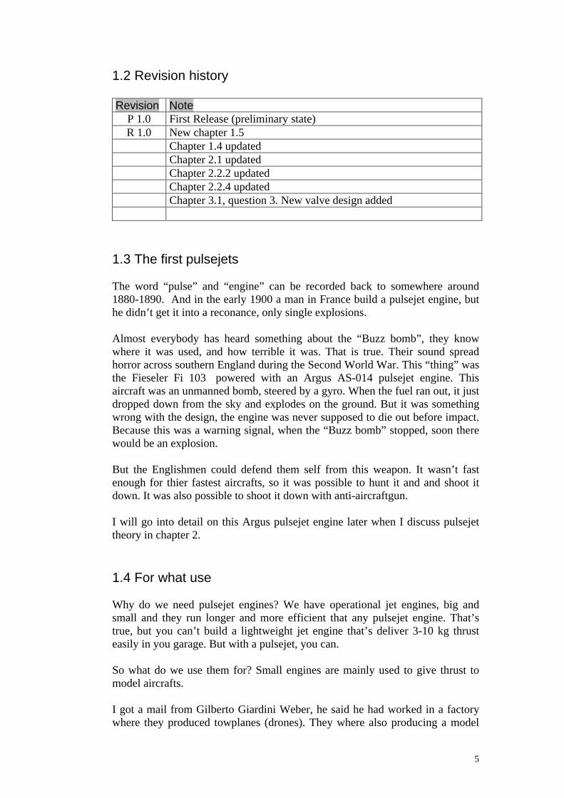
Pic No. 2 Heinz Ollarius plane, 90 mm pulsejet.
Picture to the left is Heinz Ollarius model airplane, it´s completly build fromfiberglass and honeycom and it´s very strong and super light. The engine is a 90mm pulsejet with 80 N thrust. Heinz worked with a injection pressure of 8 bar.Picture to the right is a starting attempt, Heinz (to the left in the picture) aremanaging the fuel and air pressure. Remko Klaassens (to the right) is ignitingthe engine. Unfortunately Heinz passed away a few years ago, he is by manyseen as the “number 1” pulsejet engine designer.
Remko Klaassens is now building these engines after Jean Quadvlieg gave allhis tools and equipment to him. Jean was a close friend of Heinz, he build evenmore engines than Heinz based on the 90 mm pulsejet engine. Jean Quadvliegalso made an engine for the Pulsejet team Helmond (AMTjets) and he is nowbuilding micro turbines with high thrust.
Remko also mention that the jet aeroplanes need a good pilot, and one of thebest is Bennie v/d Goor. He has a spectacular show and his motto is “Go lowand fast” but always with the safty in first place. That’s what makes him thebest.
Pictures and story comes from Remko Klaassens.
7
2. Pulsejet Theory
2.1 How it works
When you look at the material details you will think, “This must be a simpleengine” but infact, it's a rather complex engine. It’s also difficult to understandthe operation sequence.
So where do we begin? The first guy to understand the theories was the GermanPaul Schmidt. He was active from 1928 to later after the Second World Warwith his pulsejet ideas. Infact, he did not build the famous V1 engine, he justlead the Argus Company on the right track when they desiged the engine. Hehad a better and more efficent construction. But he didn’t reviel his seceretsbecause he thought that he could make a profit out of his ideas after the war. Butthe turbine jet engine was at its dawn and the pulsejet engine never became thecommercial succes that Paul once thought.
Below is my personal thought about the pulsejet engine operation sequence.
Fact, my experience
A pulsejet engine deliver thrust, gasses of burned fuel/air comes out of theexhaust pipe with such a speed that a force is created in the opposite direction.
A pulsejet engine can run without any outside help.
The pulsejet engine repeats its puls sequence at a given frequence.
The reconance frequence is among others depending on the lenght of thepulsejet engine.
Conclution, my experience
Okey, here comes the hard part. First of all, pulsejet engine is now also relatedto the word “tube”.
We begin with the fact that the tube is approx. 15-20% filled with fuel/airmixture (*), some how it detonates and the high pressure makes the gasses to bepushed out through the exhaust pipe in a high speed, propobly not above speedof sound. By reading documents and talking to other people my experience isthat the peak speed may by speed of sound but not above.
I have found that there are at least two different circumstances why a pulsejetengine operates in a resonance sequence. Simply, why the pulsejet engine run.
• The pulsejet engine has a lengt of a half wavelength of the resonancefrequenze. This means that when detonation occurs a shockwave istravelling from “valves” to the end of the pipe. Then the shockwave turns

8
and go back (reflection). This pressure resonance is what I call the staticpressure.
If we compare audio resonance theory with electrical resonance theory wewill find that they are pretty good adapteble. Resonance behavior is thesame. Electricity is also my subject field.
If we look at the resonance in an electrical cable, we look at open, close andadapted termination. Adapted termination will return none reflection. Openand close termination will return 100% but in different phase. And in thiscase it´s the open termination that is comparable to the pulsejet engine.
In a cable, 100% are reflected back, but in a pulsejet engine this is not thecase. Imagine putting a loudspeaker where the valves are placed and tune itinto the resonance frequence, should be something like X*2*f=340, whereX = pulsejet lenght in meter. f is the resonance frequence. Ofcourse willyou here the resonance sound at the open end, so this will decrease thereflected shockwave, how much is hard to tell, lets say 50-60%.
If we look at the picture below we will see 3 curves, Black color is theshockwave traveling to the end, green is the reflected wave and red are thesummurize of the two curves. Green curve has the smallest amplititude, inthis picture, color is more dark green.
Pic No. 3 Static pressure wave
PJ equals to the pulsejet engine, “tube”. + indicates high static pressure.Sequence is run from pos 1 to pos 8, then begins with pos 1 again.Explosion occurs when the static pressure goes high in pos 1. In this picture

9
the reflected wave are 50% of the forward wave. The forward wave is aconstant sinus wave. In a pulsejet engine the situation are a little moredifferent. I belive that the pressure in the forward wave won´t rise aboveatmospheric pressure after it have fall.
If we summurize the two curves (red curve) we will se that static pressurewill change more at the tube ends than in middle, so peak pressure will behigher at the valves and at the end than in the middle. If we had 100%reflection static pressure in the middle would be 0.
• As I said, high pressure makes the gasses to be pushed out of the exhaustpipe in a high speed. Due to the gasses inertia there will finally be a lowpressure inside the tube, just like pulling your finger out of a bottle and youwill hear a “plopp”. The pulsejet works exactly the same way. This lowpressure will cooperate with the static pressure resonance wave because thelow pressures apper at the same time. The reflected pressure wave is at thistime positive, but the summaries of the forward and the reflected static waveare negative. This pressure is what I call the dynamic pressure.
Let’s go back to the pulsejet sequence. After the explosion, the static and thedynamic pressure will fall. This will finally open the valves and let new fuel/airmixture enter the pulsejet engine. Next thing that happens is that the resonanceshockwave will raise the pressure and trigg the ignition, and a new sequencewill begin.
This is the basic princip behind the pulsejet engine operation. The staticpressure gives us the resonance and the dynamic pressure gives us the thrust. Ithink that it is this that makes the pulsejet engine so hard to overcome. Thestatic and the dynamic pressure must synchronize to achieve a perfectresonance.
If we summurize this discussion we will see that the shape of the pipe will affectthe reflected shockwave. If we compare to microwave theory an adaptedantenna look somthing like this.
Pic No. 4 Microwave antenna
Black arrow is the forward signal, green arrows and the black arrow has thesame energy. The reflected wave is very small compared to the forward signal.

10
If we make a pulsejet engine that looks like this the reflected shockwave willdecrease even more, and the engine will have serious trouble to run properly. Soif you would like to design a new type of pulsejet rear end you have to have thisphenomenon in your head. Another thing thats matter is also the relationbetween wavelenght and resonance pipe diameter. Equals to the pulsejet lenghtcontra diameter.
Those model pulsejet engines I have seen, have a Lenght/Diameter L/D ratio of15 to 17. Argus (V1) has a L/D of 8.7. I have not paid attention to the largmentafter the valves. The lower L/D ratio you have the more reduced reflectedshockwave you will get. My guess is that the model pulsejets have a higher L/Dratio to secure a stable resonance and to lower the resonance frequence.
I belive that there are more circumstance why a pulsejet is running, but they aretoday beyond my knowledge.
Shockwave speed
The Argus pulsejet engine had a stable resonance frequence of 43 Hz (**). Theshockwave travels with the speed of sound through the tube, speed of sound canthen be calculated to 3.49*2*43=300.14 m/s. I dont have the knowledge toculculate speed of sound in a pulsejet engine with it’s high pressure and hightemperature. But if this is true, we could have some use for this information. Tofind the reconance frequence to calculate the shockwave speed se chapter 3.1question 8.
My first pulsejet had a frequece around 170 Hz and a lenght of 590 mm.Shockwave speed must then have be 0.59*2*170/sek => 200 m/s. I think myengine did not run properly, the ignition did not occur by the shockwave. That’swhy 200 m/s is not equal to 300 m/s. My engine also change frequencedepending on fuel consumption.
The P90 has a frequence of 150 Hz, it’s lenght is 86 cm, this gives us ashockwave speed of 150*2*0.86= 258 m/s.
The following conclusion is just a guess from my point of view. If you obtain ahigher “shockwave” speed, the clearer or more effective the engine will run.Shockwave speed is the wrong word to use but it´s also the easiast word to use.It´s not the shockwave speed that´s increases. I think that it is the dead timebetween the reflected shockwave and the ignition that gets shorter, therefor“shockwave speed” increases.
As you se I´m not talking about Combustion chambers and resonance pipes anymore. Paul Smidth once said, “as long as the valve opening area, and the otherconditins of resonance sequence are met, tube shape has little effect on theoperation of the engine.” The importent thing is the exhaust pipe area contra thevalve flow area.
So when you hear people talk about combustion chamber in a pulsejet enginethay are wrong, even myself thought that once.

11
(*) 15-20% is a value calculated (or estimated) by Paul Schmidt
(**) According to Dave Brill
2.2 Equations
In this chapter I will give some clues about culculating with pulsejet engines.These equations are far away from finished, but it may be a good start tounderstand something. There are also some equations from practical examples. Iknow that there exist several different blueprints on fully operational pulsejetengines. The equations come from these engines.
2.2.1 Pulsejet operation equations
First some basic facts, I have found that the Air/Fuel ratio is something about12-13, this means that you need 12-13 kg of air to burn 1 kg fuel at groundlevel. I found this information in two different reports, I think that this is correctfor most kind of fuel types. 1 litre of air is approx. with 1 gram. Another fact Iuse is that the gas exit velocity never goes above speed of sound, right orwrong? I have approximated explosive air (air/fuel mixture) with just air,because to simplyfy it. They have almost the same weight. Let’s begin withsome variables
V = tube volume (dm^3 = litre.)f = pulsejet engine operation frequence. (Hz)va = gas exit average velocity. (m/s)F = force, thrust (N, Newton)fc = fuel consumption (gram/second)m = mass in kgt = time in second.
Equation (1){ m*va=F*t }
Here follows some practical examples.
V1 fuel consumption
V= 511 litre, f= 43 Hz. Se chapter 3.4 pulsejet plans pic 26.
20% (*) of 511 litre is 102.1. 102 litre of explosive fuel/air mixture = 0.102 kg.To burn this amount of air we need approx. 0.102/12.5 = 0.00816 kg offuel/explosion. 0.00816*43= 0.351 kg fuel/sek. fc = 351.
We know that the V1 had around 450 litre of fuel in it´s tank. 450 litre is approx380 kg. With this fuel amount it could then fly for 380/(0.351*60)= 18 minutes.Which is the flying time between the coast of France to London.

12
P90 studies
To find blueprint of this engine, check web address at chapter 3.4 pulsejet plans.
V = 2.9 litrefc = 6.7 gram/secf = 150 Hzva = 258 m/sF = 85 Newton
“fc” is based on information from the P90 homepage 1.2 kg of fuel over 3minutes. This number might be incorrect, because maybe not all fuel was usedor burned correctly in the tube. “f” was measured from a sound file at theirhomepage, se chapter 3.1 Some ideas (F.A.Q) question 8, “va” areapproximated to it’s shockwave speed, right or wrong?
From equation (1) m = F*t/va = 85/258= 0.329 kg/second. This gives us0.329/150= 2.2 gram gas/explosion. At least 2.2 are less than 2.9 because thetube contains only 2.9 gram of air. I have read that the pressure during theintake cycle is the same as in ambient medium. That’s why there can’t be anymore air than 2.9 gram in the tube.
If we check the fuel consumption instead, 6.7 gram of fuel needs 6.7*12.5= 84gram of air/second. 84/150 = 0.56 gram of air/explosion. By an “incident” 0.56gram is exactly 20% of the tube volume which Paul Schmidt said it should be.
Conclution might be that, of totaly 2.9 gram air. 2.2 gram is pushed out by 0.56gram air/fuel mixture in an average speed of 258 m/s. And it is a BIG might, Ihave not calculated with any energy, nor temperature, nor pressure, norefficient, so please correct me if I’am wrong.
(*) 15-20% is a value calculated (or estimated) by Paul Schmidt
2.2.2 Valve flow area
Brauner, Alpha, Sov faa, B-12, Aerojet, PAM, Silnik. Is it possible that theyhave something in common. I have choosen these engines because they havealmost the same construction. Valves and a tube as resonance pipe. Let’s checkthe exhaust pipe area contra the valve flow area just as Paul Schmidt said wasthe critical part in a pulsejet engine design.
Exhaust pipe area is simple to understand. It’s the area of a circle =r^2*3.141592. This of cousre if the exhaust pipe has circle shape.
Valve flow area is little more complex to calculate. It is depending on the valvedesign, shape and of course the area that the valves are covering. Look at thevalve design on the pulsejet engines mentioned above, flower valve shape. Theyhave 50-60 % valve flow area contra the valve coverd area. (*) Look at theexample below and you will understand it better.

13
It is also importent to know that this % number can change depending on theshape of the valve washer, or how smothly the valves can open and close. It isalso depending on alot of other things in more or less degree.
Example of valve flow area:
There are 10 valves and they are covering 10 circular holes with a diameter of10 mm in a flower valve shape. What is the valve flow area? One hole has anarea of (10/2)^2 * 3.1415= 79 sqr mm, ten holes has an area of 79*10 = 790 sqrmm. It was a flower valve shape so the valve flow area is only approx. 55 % ofthe culculated area, 790*0.55 = 430 sqr mm. Answer: The valve flow area is430 sqr mm.
But with the Argus pulsejet design the valve flow area was approx. 75% (**) ofthe total area. Later you will se the calculations when I compare this engine withthe small model pulsejet engines.
So, now you know what the exhaust pipe area and the valve flow area is. Let’sfind them in the drawings. For all these engines I have found the valve flow areaas the smallest area before the valve. I build my equation upon this fact, that thepulsejet designers have tried to match the valve flow area with the smallest airinput area. When I try to meassure the valve covered area, I find that they differ55% from the smallest air input area. With this as basis I say that the smallestair input area is the valve flow area. Area in sqr mm.
Pulsejet engine Y=Valve flow area X=Exhaust pipe areaBrauner 452 907Alpha 381 531Sov faa 661 1195B-12 221 531Aerojet 603 1075PAM 506 907Silnik 531 1134
Pic No. 5 Valve flow area table
If you put these values into excel paper and then try to find linjarity, you willcome up with the equation
(Europe) Y = 0,4922*X - 37. (mm)
(USA) Y=0.4922*X-1,45 (inc)
If you build a larger engine you can forget about “37” or “1,45”.
This equation is the most importent of all, one reason is that the engine must getthe right proportion of air/fuel mix so when it detonates, the exact amount of
14
gases creates so a new sequence can appear. The gases must have the rightvelocity when it leaves the tube so new fuel and air can enter the tube.
When you look in the front of a pulsejet engine you will se that it has a smallerdiameter than where the valves are. This is because we want to match that areawith the valve flow area.
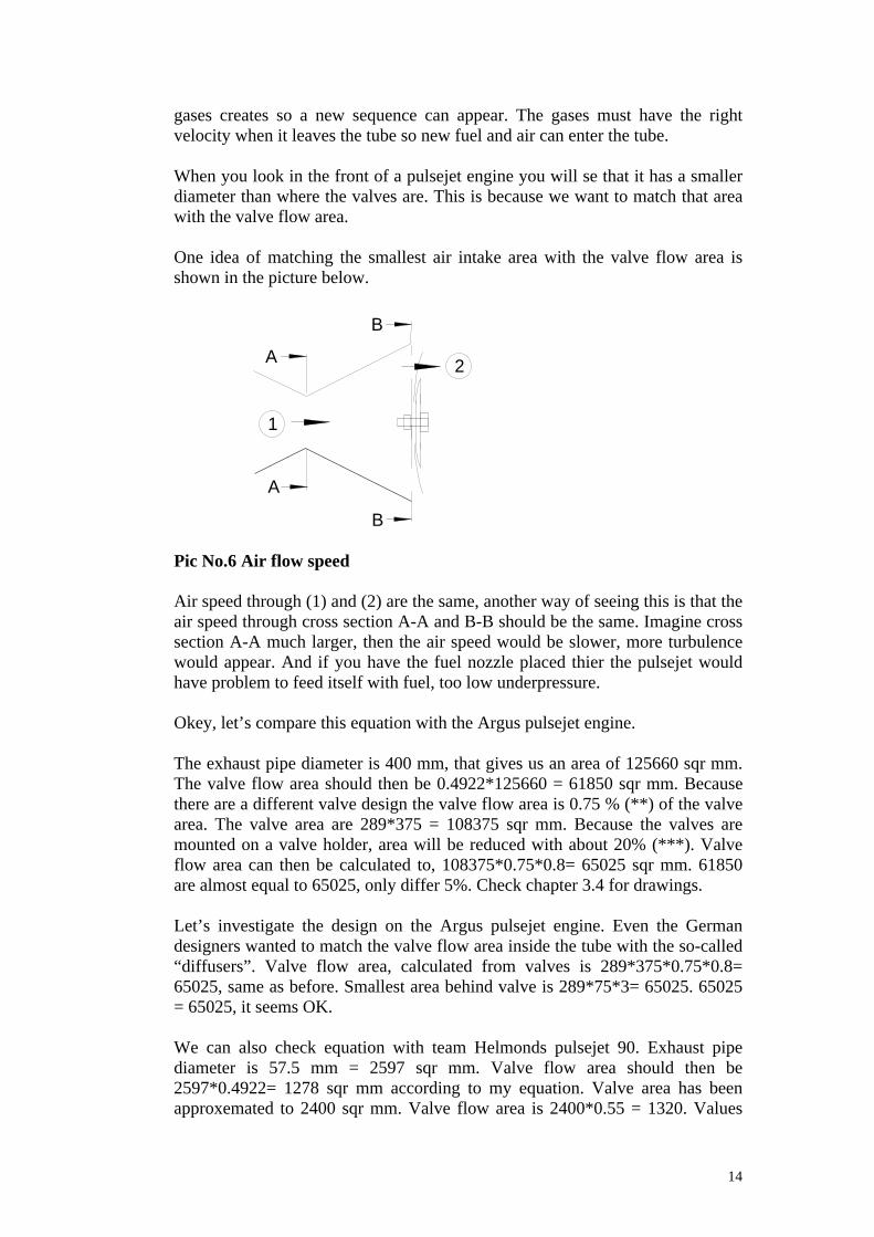
One idea of matching the smallest air intake area with the valve flow area isshown in the picture below.
Pic No.6 Air flow speed
Air speed through (1) and (2) are the same, another way of seeing this is that theair speed through cross section A-A and B-B should be the same. Imagine crosssection A-A much larger, then the air speed would be slower, more turbulencewould appear. And if you have the fuel nozzle placed thier the pulsejet wouldhave problem to feed itself with fuel, too low underpressure.
Okey, let’s compare this equation with the Argus pulsejet engine.
The exhaust pipe diameter is 400 mm, that gives us an area of 125660 sqr mm.The valve flow area should then be 0.4922*125660 = 61850 sqr mm. Becausethere are a different valve design the valve flow area is 0.75 % (**) of the valvearea. The valve area are 289*375 = 108375 sqr mm. Because the valves aremounted on a valve holder, area will be reduced with about 20% (***). Valveflow area can then be calculated to, 108375*0.75*0.8= 65025 sqr mm. 61850are almost equal to 65025, only differ 5%. Check chapter 3.4 for drawings.
Let’s investigate the design on the Argus pulsejet engine. Even the Germandesigners wanted to match the valve flow area inside the tube with the so-called“diffusers”. Valve flow area, calculated from valves is 289*375*0.75*0.8=65025, same as before. Smallest area behind valve is 289*75*3= 65025. 65025= 65025, it seems OK.
We can also check equation with team Helmonds pulsejet 90. Exhaust pipediameter is 57.5 mm = 2597 sqr mm. Valve flow area should then be2597*0.4922= 1278 sqr mm according to my equation. Valve area has beenapproxemated to 2400 sqr mm. Valve flow area is 2400*0.55 = 1320. Values
1
2A
B
A
B

15
differ only 3.5%, so it looks good. According to Helmonds drawing the smallestair input area is 1440 sqr mm. (43.5 mm diameter-fuel injector). This numberdiffers 10% from what we expect.
As I said before, all these values depend on alot of things. They can change verymuch if something is alittle bit different. So take these numbers with a pinch ofsalt.Most importent thing is still the resonance operation sequence. The pulsejetengine must be in a resonance. This may be difficult to achieve, but it can bedone. Se chapter 3.1 question 4 for practical example.
(*) 50-60 % is a value calculated by Paul Schmidt. I have recievd it trough DaveBrill(**) 75 % is a value calculated by Paul Schmidt. I have recievd it trough DaveBrill(***) 20% is estimated by me, Argus drawings as basis.
2.2.3 Exhaust pipe lenght
My experience is that with long pipe, you will have low reconance frequence,the engine can run by itself. Short pipe, high frequence and the engine can’t runwithout exarnal input airflow. According to Dave Brill, the lenght has littleeffect on output power as long as the conditin for resonance sequence are met.Because in a low frequence the fuel charge are larger than higher frequence.Low frequence and larger explosions becomes equal to higher frequence andsmaller explosions.
This is exaclly what I have said before. If you increase tube volume, you willincrease fuel mixture and this gives us larger explosions. And it’s also easy toprove that the lenght has nothing to do with the output power for a tube chapedas a pipe.
Pic No. 7 Tube shape
Equation to use is m*v=F*t. m = mass = X % air volume of the total volume inthe pipe. This is X * D^2 * 3.1415 * L / 4. t = to 1 second, during 1 second fexplosions occur, f = frequence. f = v/L*2. This are put together and ends upwith
F (Newton) = (X * D^2 * 3.1415 * L * v^2 )/(L * 8)
L
D

16
As you se L/L = 1, Output power depends on only the diameter of the pipe andgas exit velocity. Final equation looks like this.
F (Newton) = (X * D^2 * 3.1415 * v^2 )/8
If we look at our model pulsejet engines, this equation won’t be adaptablebecause the enlargemet at the valves. For those engines a specific lenght willproduce a maximum output power. This due to, for short pipe, the (delta) lengthis not linjear to the (delta) volume. For long pipes it is linjear. Therefor, longpipe will be closer to maximum output power than short pipe.
The main reason why the pulsejet engine looks like it does is becauce the valvesneed alot of space in the tube. That is why it has a larger diameter where thevalves are.
Comparing exhaust pipe area with total lenght of the pulsejet engine gives youthis equation. Total lenght is all lenght after the valves.
Pulsejet engine Y=Total lenght X=Exhaust pipe areaBrauner 490 907Alpha 485 531Sov faa 670 1195B-12 600 531Aerojet 610 1075PAM 810 907Silnik 620 1134
Pic No. 8 Exhaust pipe lenght table
(Europe) Y = 0.152 * X + 470 (mm)
(USA) Y = 3.88* X + 18,66 (inc)
This equation is only valid for small model pulsejet engines. Remember thatit’s better to begin with a long pipe and just cut it during the testrun.
To find the resonance frequence on your engine, se chapter 3.1 question 8.
2.2.4 Thrust (Output power)
There are a formula to culculate the output power, and according to Dave Brillno engine has exceeded that formula. A correct built pulsejet engine delivers4.2-4.6 pounds of thrust / sqr inc. Sqr inc means the area of the exhaust pipe. Inmetric it will be 0.295 up to 0.323 kilo of thrust / sqr cm. Se chapter 2.2.3Exhaust pipe lenght for more info.
Example, if you have an engine with the exhaust pipe area of 4 sqr inc, thisengine will then deliver approx. 4.4*4=17.6 pounds of thrust.

17
Let’s compare with the Argus pulsejet engine. 400 mm diameter = 15.75 inc.Exhaust pipe area is culculated to 195 sqr inc. 4.4 pouds/ sqr inc gives us theoutput power of 4.4 * 195 = 857 pounds of thrust. And that is just what theArgus engine deliverd at it’s maximum.
Compare Helmonds pulsejet 90 with this equation. 57.5 mm = 2.26 inc. Exhaustpipe area is 4.01 sqr inc. 4.4 * 4.01 = 17.6 pounds. And that is 7.9 kg. Pulsejet90 delivers 8.6 Kg of thrust.
Se 2.2.3 Exhaust pipe lenght for pre studie on this equation.
F (Newton) = (X * D^2 * 3.1415 * v^2 )/8
If we add X = 0.75 as my result in the P90 engine 2.2/2.9 = 0.75, se chapter2.2.1. is equal to 75 % of the air in the tube, leaves the pipe. v are approx. to 300m/s. This gives us the final “unusable” equation.
F (Newton) = 26506 * D^2 , D in meter.
If Einstein had E=mc^2, I have F=2.65*D^2, D in cm.
If we compare my result with Dave Brills result. 0.3 kilo/ sqr cm are convertedto F= 2.31*D^2. I think 2.31 are pretty close to 2.65, especially with all theuncertainty there are in my equation.
2.3 Argus pulsejet (V1)
I don’t know if my conclusion below is correct, but this is the way that I havelearned it. Dave Brill explained the starting sequence for me.
The development of the pulsejet engine increased 1937 when the ArmyWeapons Office got involved, and in November the 13, 1939 the secondpulsejet prototype was proved with good result. Work continued, but whenproposals where made in 1939 and 1941 to develop operational flying bombs,they were turned down. As you know, war was heading their way. A big stepwhere made on 30 April 1941 when the original pulsejet engine was flighttested under a dubble-decker. Due to increasing RAF attacks on German cities,rising losses of Luftwaffe bombers and problems with the development of theV-2, things got change. After June-July 1942, the development of the V-1started. Some minor changes where made on the engine, and soon they have astable operational pulsejet engine to use in the V1 project, the Argus AS-014.
The first pulsejet powerd flight was performed on Christmas Eve 1942. Duringthe evelopment of the flying bomb at Peenemunde, they encounterd a series oftroubles. To resolve these problems, a piloted flying bomb was developed, inwhich the warhead was replaced by a cockpit in which a test pilot could fly themachine while lying prone. Test flights were performed and uncovered thedefects in the machine.

18
Several flying bombs were launched towards Sweden (my home country) todetermine their range and other performance characteristics; and on June the 13,1944, the first of over 10000 V-1 was launched towards London. Even more V-1: s was launched, but on other targets. 32000 V-1: s where built during the war.
Starting sequence
Argus pulsejet engine was started with acetylene because of the gas's highflamability in colder weather. It was then switched over to it's liquid fuel andallowed to run for a few moments before the rockets were fired. The rocketswere only used to accellerate the V-1 to take-off speed within the short runallowed by the take-off ramp.
Some notes have been made that they coverd the rear pipe end with a piece ofcardboard, just to hold the start mixture in the pipe before ignition.
Valves
One of the main part in a pulsejet engine are the valves, and in the Arguspulsejet the solution is perfect. Airflow meets the valves in an angle of approx.30 degrees. And when it starts to open up, the angle decrease from 30 to somewhere around 10. Our flower shape valves are different. Airflow meets thevalves at 90 degrees and when these are fully open the angle is approx. 75degrees. This is why Argus pulsejet valves compared to flower shape valves aremuch better.
Se chapter 3.1 question 3 for picture
Ignition
To ignite the pulsejet engine a sparking plug is mounted on the top of theengine.
Fuel
There are 9 fuel injectors, and they are placed just after the valves. There arealso 3 other nozzles for starting and for pressure sence. During the startsequence fuel was blow through these nozzles. When the V1 is flying thenozzles was sensors.
There are two fuel pipes going from the fuselage to the engine, the one closestto the valves are for fuel, the other one are used for starting and for preassuresence.

19
Pic No. 9 Argus pulsejet engine
This is the famous Argus pulsejet engine, it is a little bit longer than it is in thispicture. Se chapter 3.4 Pic No.26 Argus drawings
Thrust, static approx. 500 pounds, 210 kgThrust, flying approx. 750 pounds, 320 kgLenght: 137.4 inc 349 cmWidth: 22.4 inc, 57 cmFuel: Low octane fuel.
Fuel consumption: approx. 26 litre/minute
Pic No. 10 Fieseler Fi 103 (V1)
Picture taken at a War Museum some kilometers from London, I´ve forgotthe name of it.

20
3. Building your own pulsejet
3.1 Some ideas (F.A.Q)
I will in this chapter give you some clues about how to build pulsejet engines. Ifyou for example have all special equipment, I recomend you to build an alreadydesigned pulsejet engine, ex. Brauner design. But if you, as me don’t have alltools you will have to change the design. I will also try to answer some otherimportant questions.
1. Where should the fuel enter, “inside” or “outside” the engine?2. How long exhaust pipe (resonance pipe) must I have?3. What kinds of valve typs (designs) are there?4. I want to design my own pulsejet engine, how do I do?5. What kind of fuel should I use?6. How do I easily put all parts together?7. How do I start the engine?8. Do the frequence match the resonance pipe lenght?
1. Where should the fuel enter, “inside” or “outside” the engine?
With inside I mean that the fuel injector is placed just after the valves, equal tothe place where the “explosion” begins, occor. Outside means that it is placedjust before the valves.
The main difference is that if you put the fuel injector inside it would be safer,less chance that flames comes out in the front of the engine. I also think that thefuel consumption will be a little less. Otherwise there are small or nonedifferences.
2. How long exhaust pipe (resonance pipe) must I have?
I would recommend you to make it a little longer. I think it easier to start theengine with longer pipe than shorter. And it definaly more easier to cut than tomake it longer.
Don’t make the wide part to long, only approx. 20% of the total lenght.
Se chapter 2.2.3 for equation.
3. What kinds of valve typs (designs) are there?
A. Flower valve shapeB. Argus design (grid type)C. My own desigen (reed shape)D. Angled valve design
21
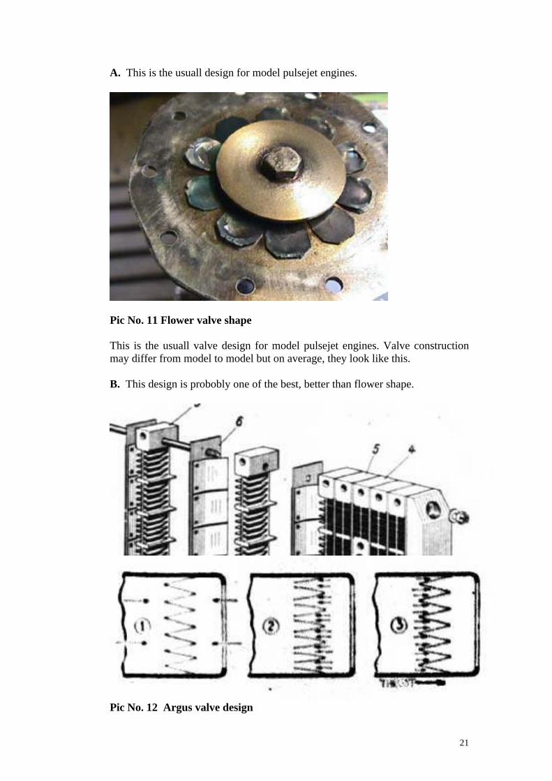
A. This is the usuall design for model pulsejet engines.
Pic No. 11 Flower valve shape
This is the usuall valve design for model pulsejet engines. Valve constructionmay differ from model to model but on average, they look like this.
B. This design is probobly one of the best, better than flower shape.
Pic No. 12 Argus valve design

22
Highest picture shows how the valves are assambled. Pictrue below describe it´sfunction. (1) Same pressure inside and outside the engine. (2) Low pressureinside engine, valves open up and new air/fuel enters the engine. (3) Explosionoccor and the valve stop the forward flow.
C. My own design (reed shape) is a combination of the two above.
Pic No. 13 My own valve design
(1) Nothing is mounted on the valve plate, just a hole in the plate (2) Valve isassambled. (3) Valve holder added with bolt trough everything. Valve is nowcomplete. I have also seen this valve shape in two stroke engines, I think it’scalled “reed valve” or something.
D. Angled valve design. This is an attemt to reduce the “large part” diameter
Pic No. 14 Angled valve design
This valve design has two big differenses from the 3 examples above. It is notsymetric and the air/fuel mixture won´t enter the tube symetric. Will it work? I
1 2 3
48 mm75 mm
170 mm 500 mm
TubeValve plate
Valve plate
23
really don´t know that, this is just an idea. My primrary goal with this design isto create a good, simple and easy build pulsejet engine. If I compare the ratio,“valve” diameter (largest) and the resonance pipe diameter, between this engineand the P90 we will se that they are the same. If my engine have the rightdimensions and the asymmetric design won´t reduce power, this engine mightbe as good as the P90.
What is the advantage with this design, practically this engine will be very easyto build. I have right now the building description in my head and I will printthem when I build this engine. The advantage theoretics will be a larger crosssection valve area. This will increase the valve coverd area and ofcourse thevalve flow area/ factor. Since valves don´t have to open/bend so much too fullyopen up.
Negative things might be some turbulens in the air intake, and it will be difficultto reduce them. One thing that I don´t know anything about is how much theefficiency will be reduced due to the asymmetric design.
4. I want to design my own pulsejet engine, how do I do?
First of all you have to know how strong engine you need, that’s importent,because it depends on the rest of the construction. I want my engine to deliver25 pounds of thrust, what do I do? Okey! Let’s calculate exhaust pipe area,25/4.2 = 5.95 sqr inc. This gives us a diameter of 2.75 inc The valve flow areacan be calculated to 5.95*0.6552 = 3.9 sqr inc. So if you use a flower valveshape the area coverd by the valves should be atleast 3.9/0.55 = 7.1 sqr inc. Andwith 18 holes, each hole must be 0.39 sqr inc.
Now you start to se what a big engine this will be. Let’s se how long it needs tobe. 5.95*3.88+18.66 = 41.8 inc long exhaust pipe (tube). Make it instead 50 incjust incase.
The wide part after the valves can be around 8 inc long (0.2*41). Now let thecon and the reconance pipe be total 50-8= 42 inc. This will make the exhaustpipe 42+8= 50 inc long. This is ofcourse excluding valves and “valve house”
As I said before, the smallest air input area is equal to valve flow area, equal to3.9 sqr inc. This is equal to a diameter of 2.23 inc. The smallest diameter wherethe air enters the pulsejet engine should be 2.23 inc.

24
Pic No. 15 Pulsejet engine design
(1) Valve plate with 18 holes. Each hole has an area of 0.39 sqr inc. (2) Tube.What is missing is the valve house front, use my design as in question 7 in thischapter. Smallest area should be 3.9 sqr inc. Equal to a diameter of 2.23 inc.This drawing is more or less an overview. Don’t build anything with thisdrawing as basis.
Tip: My experience is that it is better to make the valve flow area a little largerthan found in my equation. Because in reality, the engine will then be a lot moreeasy to start. Even increase the smallest air input area a little. If you make thevalve flow area too small you will have serious trouble with your engine (Iknow). My equation is more or less for an optimized design when everythingworks perfect.
5. What kind of fuel should I use?
I have right now none experience in this matter. I have only used car petrol asfuel. But I do know that some guys in Netherland are using a fuel with the
3.86 inc
20.0°
3.8
6 in
c50 in
c
2.7
5 in
c
12
25
compounds, 53 % Kerosine JP-4 or Jet A-1. 40 % Gasoline. 7 % Propyleneoxide C3-H6-O. I suggest that you use this fuel.
6. How do I easily put all parts together?
Look at my drawings and you will findout a easy way to build a pulsejet engine,maybe not the best but you can do it in your garage.
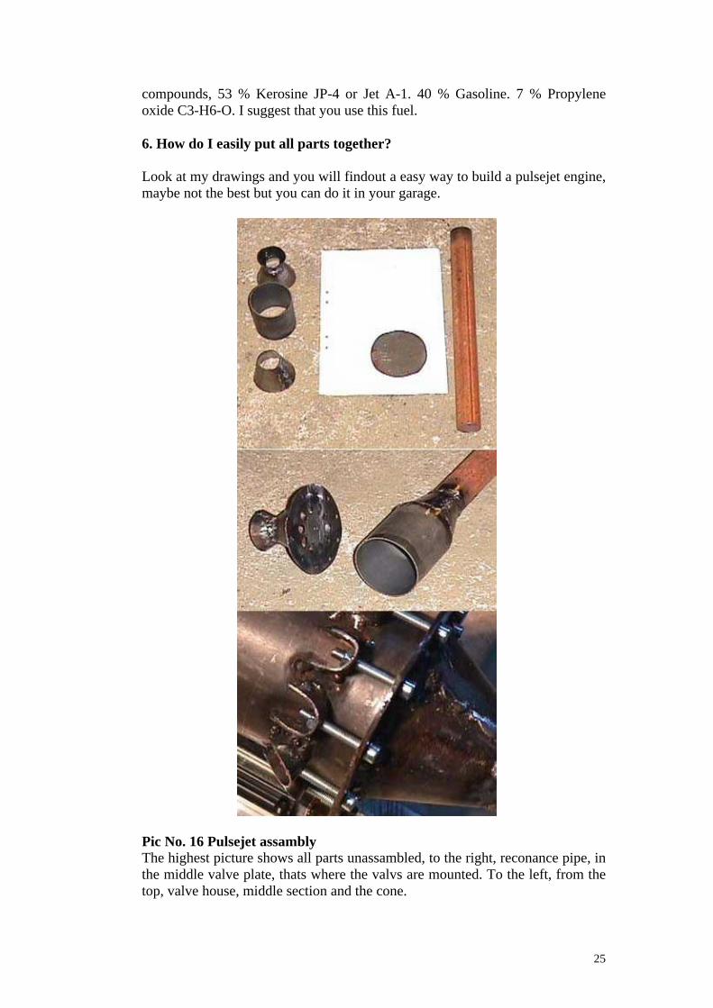
Pic No. 16 Pulsejet assamblyThe highest picture shows all parts unassambled, to the right, reconance pipe, inthe middle valve plate, thats where the valvs are mounted. To the left, from thetop, valve house, middle section and the cone.
26
In the middle picture you can se the valve house asambled. Holes have alsobeen drilled in the valve plate. The tube is now almost finnished
The lowest picture shows how to mounted the valve house on to the tube. I haveused 10 M 4 bolts to keep them together.
This is a very simpel way to build a pulsejet engine. Please don’t forget to addthe cone in the valve house as I did. Without this part the air won’t go smooththrough the valve house and the engine may not run properly.
7. How do I start the engine?
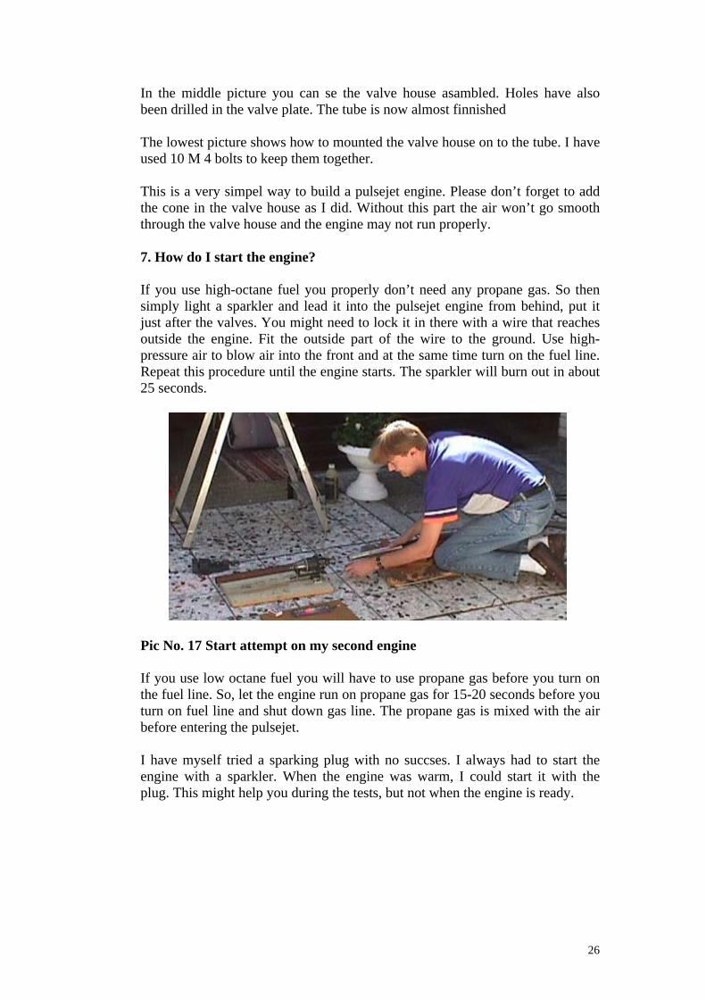
If you use high-octane fuel you properly don’t need any propane gas. So thensimply light a sparkler and lead it into the pulsejet engine from behind, put itjust after the valves. You might need to lock it in there with a wire that reachesoutside the engine. Fit the outside part of the wire to the ground. Use high-pressure air to blow air into the front and at the same time turn on the fuel line.Repeat this procedure until the engine starts. The sparkler will burn out in about25 seconds.
Pic No. 17 Start attempt on my second engine
If you use low octane fuel you will have to use propane gas before you turn onthe fuel line. So, let the engine run on propane gas for 15-20 seconds before youturn on fuel line and shut down gas line. The propane gas is mixed with the airbefore entering the pulsejet.
I have myself tried a sparking plug with no succses. I always had to start theengine with a sparkler. When the engine was warm, I could start it with theplug. This might help you during the tests, but not when the engine is ready.
27
8. Do the frequence match the resonance pipe lenght?
If you have problem with your resonance frequence, can you measure it and seif it match the reconance pipe lenght. In this program the frequance scale beginsat 80 Hz and goes up to 450 Hz, it’s used to find guitar chords.
First you record a wave file of the sound, a taperecorder works perfect. Recordthe sound in the computer through the soundcard in .wav format with atleast11025 sample speed and 8 bits. Then download “dsChordFinder” from theinternet. Shareware version will only work for 30 days. Start “dsChordFinder”and open your wave file. Press “Play” and when you hear your engine clearpress “Stop”, go to the “Frequence Window”, the lowest top are the resonancefrequence or an overtone, It may be difficult to find a top, or to know which oneis the correct, but after a while you will find it.
Investigating V1 sound over London, found at “www.zenza.se” , I measured thethird overtone to 230 Hz down to 150 Hz, fly by. So mid frequence is 190 Hz,this gives us a resonance frequence of 47.5 Hz, that is almost equal to 43 Hz. Ifwe culculate the lowest possible speed we found out that it is 56.6 m/s => 204km/h, Doppler effect. Lowest speed if V1 was passing straight over therecording media on low altitude. Which properly not happen, so the speed washigher.
3.2 My pulsejets
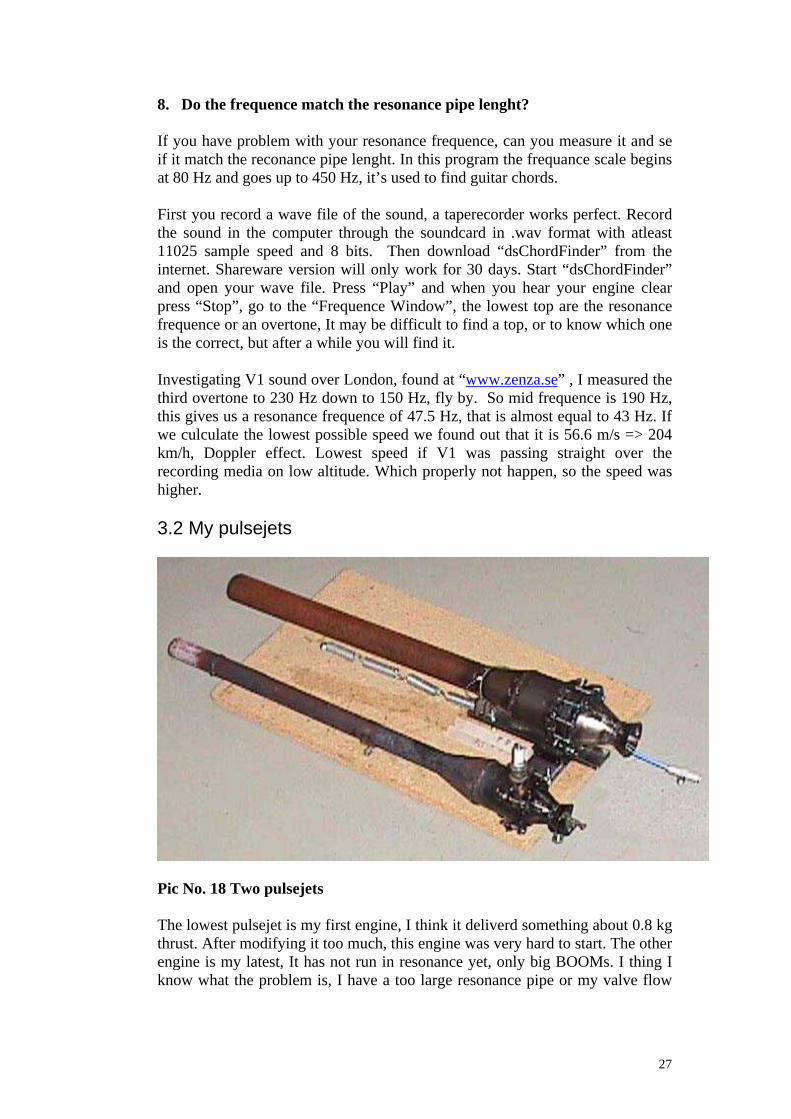
Pic No. 18 Two pulsejets
The lowest pulsejet is my first engine, I think it deliverd something about 0.8 kgthrust. After modifying it too much, this engine was very hard to start. The otherengine is my latest, It has not run in resonance yet, only big BOOMs. I thing Iknow what the problem is, I have a too large resonance pipe or my valve flow

28
area is too small. So there are two ways to fix it, change pipe or increase valveflow area.
The fuel injector is placed before the valves on both pulsejets.
The Argus pulsejet engine was built in steel, except the valve holder. I havemyself used the same idea. My valves are made of blade steel or spring steel.The rest is mainly biult of steel pipes and steel plates.
Check out my homepage, there will you find more info about my pulsejets,“http://www.geocities.com/Area51/Rampart/9722/welcome.htm”.
3.2.1 Building Description
Se chapter 3.4 Pulsejet plans “Pic No. 25 My own drawing”. All numbersdescribed in this text has a coresponding number in the drawing.
This is the building description of my latest engine, design has been changes soit should work now. Look at my homepage for latest information, se chapter 3.2“My pulsejets” for internet address.
Engine consists of 7 main steel parts. Rest is valves, bolts, nuts, fuel injectorand holds.
Part namn: Material:(1) Resonance pipe Steel pipe(2) Wide part of the tube Steel pipe(3) Con between (1) and (2) Steel plate(4) Valve plate Steel plate(5) Con (back part of valve house) Steel plate(6) Con (front part of valve house) Steel plate(7) Valve washer Steel plate
(8) Valves Spring steel or blade steel.(9) Bolts Steel(10) Nuts Steel(11) Holds Steel(12) Washer Steel(13) Washer Steel(14) Anti-trubulence cone Aluminium or steel
(9) and (10) are ordinary bolts and nuts, 1, M6x25 and 10, M4x30.
First of all you can manufactor all separate details. No. 1 and No. 2 are readywhen you have cut them in its correct lenght. With No. 3 you’ll have to bend toa con, weld the splice. No. 4 is a little more difficult. Drill a hole i center, thenyou have to drill all valve holes, use a file to change the shape of the holes.Remember that the “valve” side MUST be even, if not, valves can never be tightand the engine won't run.
29
After that you drill all periphery holes. They are later used to attach the tube.This is a very importent part, do this very carfuly. Do the same with No. 5 and 6as with No. 3. Use a lathe and make No. 7. This part is also importent, but thispart is easy to reproduce and exchange. No. 14 is made of aluminium or steel,this detail will reduce the turbulence in the valve house.
Weld No.5 and 6 together. When you are satisfied with your valve plate, weld ittogether with No. 5 and 6. Remember that it’s more difficult to change theshape of the valve plate after this procedure. Before you do anything thing withthe tube part, make sure that “valve” side of No. 2 is flat and even. Because thisside have to be tight when its mounted to the valve plate. Now weld No. 3 to theother side of No. 2. And then No. 1 to No. 3. Now the “tube” is ready.
Cut out No. 11 from a steel plate and drill a hole in the middle, make the hole alittle larger than the bolt. Now it time to weld these holds to the tube. Irecommend you to first weld two holds on opposite side of the tube. Fit thevalve house very easy on to the tube with two bolt and nuts. Use the remainingholes to weld the remaining holds.
Now it begins to look like an engine. Now its time for the valves (8), cut thevalves so they overlap the hole with at least 0.5 to 1 mm on every side..Nextstep is to mount them on the valve plate. This is the simplest way. Mount thevalves one by one, use tape to fix one valve steady. When you are finnished, allvalves should be attached with a piece of tape. Next step is to screw the valvenut.
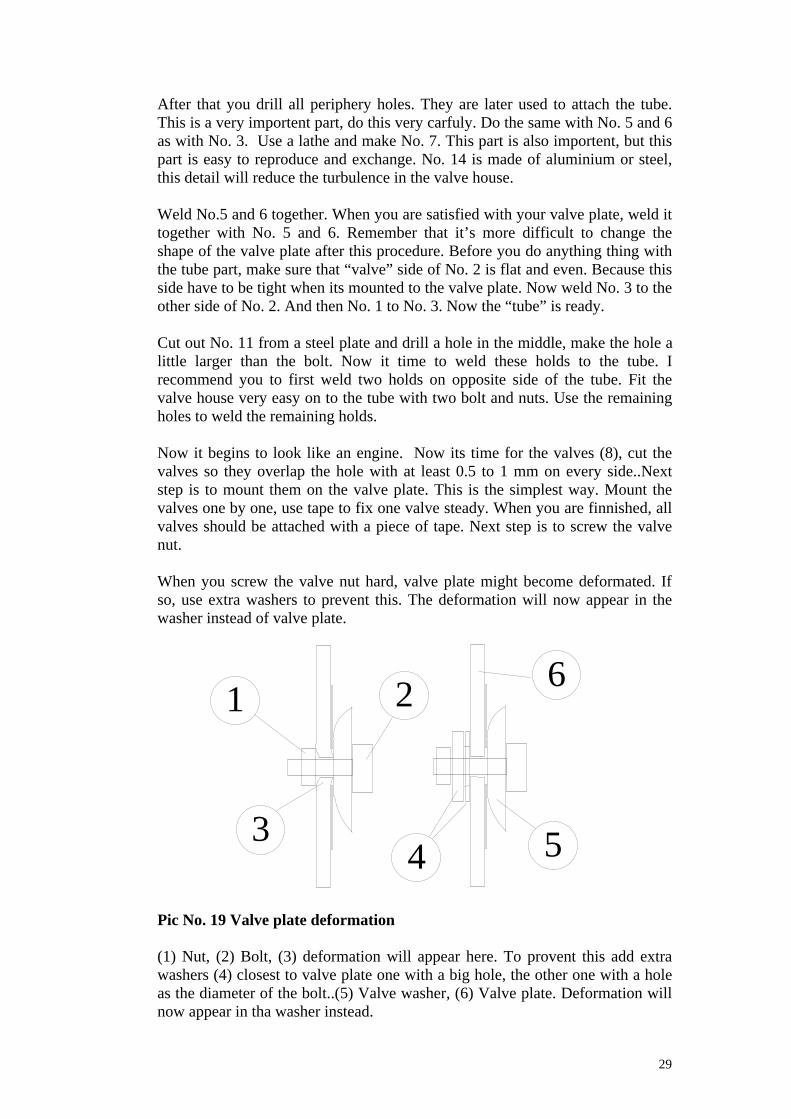
When you screw the valve nut hard, valve plate might become deformated. Ifso, use extra washers to prevent this. The deformation will now appear in thewasher instead of valve plate.
Pic No. 19 Valve plate deformation
(1) Nut, (2) Bolt, (3) deformation will appear here. To provent this add extrawashers (4) closest to valve plate one with a big hole, the other one with a holeas the diameter of the bolt..(5) Valve washer, (6) Valve plate. Deformation willnow appear in tha washer instead.
1 2
34 5
6
30
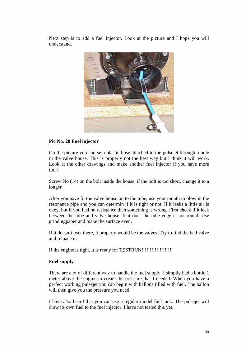
Next step is to add a fuel injector. Look at the picture and I hope you willunderstand.
Pic No. 20 Fuel injector
On the picture you can se a plastic hose attached to the pulsejet through a holein the valve house. This is properly not the best way but I think it will work.Look at the other drawings and make another fuel injector if you have moretime.
Screw No (14) on the bolt inside the house, if the bolt is too short, change it to alonger.
After you have fit the valve house on to the tube, use your mouth to blow in theresonance pipe and you can determin if it is tight or not. If it leaks a little air isokey, but if you feel no resistance then something is wrong. First check if it leakbetween the tube and valve house. If it does the tube edge is not round. Usegrindingpaper and make the surface even.
If it doesn’t leak there, it properly would be the valves. Try to find the bad valveand relpace it.
If the engine is tight, it is ready for TESTRUN!!!!!!!!!!!!!!!!!!!
Fuel supply
There are alot of different way to handle the fuel supply. I simpliy had a bottle 1meter above the engine to create the pressure that I needed. When you have aperfect working pulsejet you can begin with ballons filled with fuel. The ballonwill then give you the pressure you need.
I have also heard that you can use a regular model fuel tank. The pulsejet willdraw its own fuel to the fuel injector. I have not tested this yet.

31
3.3 Future project.
Later in the future I will start to build a large pulsejet engine, smaller than theArgus, but still no model pulsejet engine. It will deliver 70-80 Kg thrust and Iwill use it as propellant for my ice yacht. With this engine I will try to use myown valve design, se chapter 3.1 question 3. When doing so I will “try to”reduce the diameter of the wide part. Resonance pipe diameter must be 17 cm,lenght about 2 meters.
Calculations: Valve flow area must be 226*0.4922=111.7 sqr cm. Valve areamust then be 111.7/0.7=159 sqr cm. Valve area are approxemated to be2*1.2*13*6=187 sqr cm. I’m not sure about this, because I have no experiencewith this type of valve design. So I presumably have to redesign the pulsejetlater when it comes to resonance pipe diameter and smallest air intake diameter,smallest air intake are right now 12 cm diameter =>112 sqr cm.
As I said, this project is somewere in the future, don’t expect anything tohappend within 2-3 years.
Pic No. 21 Large pulsejet engine design
(1), Front cone, (2) Valve plate, 78 valves, (3) The tube, (4) One valve row with13x2=26 valves.
Only thing that differ this engine from the rest model pulsejets are the valvedesign. I am not really sure if I need the front cone, I will instead match thevalve flow area inside the engine with “diffusers”, just like the Argus engine.
A
AA-A
17 cm
30 cm
12 cm
1 2 3
3
1.2 cm
21 cm 4
1
32
Pic No. 22 Ice yacht
Speed… over 200 Km/h? Fuel consumption? 5 liter/minute. Dangerous.. yes.
Side view
Front view

33
3.4 Pulsejet plans.
Brauner drawings, Alpha drawings, My own drawing , Argus drawings. If youwant the drawing on the Team Helmonds pulsejet 90, please go to the internetaddress “http://pulsejet.amtjets.com”.
All measures are in metric “mm”
Pic No. 23 Brauner design
34
Pic No. 24 Alpha design

35
Pic No. 25 My own drawing
36,0°
10
46
14
82°
141
78
153°
153°
87
52
51
25
83
24
65
86
550
32
All unmarked steel are 1.5 mm thick 3
24
526
19
139
4
14
24 3
3
6
24
11
2 13
4
4
5
5
6
6
8
12
13
11
910
7
Designed by Fredrik Westberg
3
R 60
3
22
27
14
M6
36
37
Pic No. 26 Argus pulsejet engine
This ”Swedish written” blue print is made from V1 prototypes who was firedtowards Sweden in the begining of the war to determind performancecharacteristics. Se chapter 5 Glossory. For translation on some Swedish words.
Go to Kenneths homepage if you want the drawings in a better quality, therewill you also find more than 17 other pulsejet plans availble to download forfree. “http://www.pulsejets.com”.
4. Conclusion.
Pulsejet engines compared to jets are very easy to build. So, if you are buildingmodelaircrafts and are interested in highspeed. I can recommend you to build apulsejet engine. But please go into this project with an open mind and a motto,“It dosen’t have to work” cause otherwise you might be disapointed and angryon me, and it’s not my fault.
You can also build this engine if you want to do something odd or terrorise yourneighbors. Cause it has a real terrible sound.
Hope you understand the pulsejet engine a little better now, cause that is whatthis paper was suppose to do.
If anyone want’s to add/rewrite anything to this document, please dont hesitateto contact me.

38
5. Glossary
“Valve flow area” is the real input area that the pulsejet engine experienceduring it’s reconance. This area is a less than the area coverd by the valves, thisdue to the valves inherta, and that they will never be realy fully open.
“Valve opening area”, I’m not sure but I think it’s the same as valve flow area.
“Valve coverd area” is the hole area in the valve plate, valves are covering thisholes.
“Luftintag” trans. Airintake.
“Ventilgitter” trans. Valvegrid
“Diffusor” trans. Diffuser
“Tändstift” trans. Sparking plug
“Förbränningskammare” trans. Combusting chamber
“Bakre infästning” trans. Rear holds.
“Utblåsningsrör” trans. Exhaustpipe.
6. Sources
“Dave Brill” has give me a lot of information about the pulsejet theory, he hasalso been a great help with discussion things of different matter.
“Leslie W Lassiter” Technical note 1756 “Noise from intermittent jet enginesand steady-flow jet engines with rough burning”
“D.Z.G” (Germany Contemporary History, personal homepage) had someinformation about the Argus pulsejet engine.
“Greg Goebel” had some information about the V1 project.
“Göran Johansson”, here I found pictures, drawings on the Argus engine
“Kenneth Möller” had drawings on some model pulsejet engines. He’shomepage address is “http://www.pulsejets.com” according to me it’s one of thebest.
“Team Helmond”, I have used their engine design as basis on my research.
“Eric Van den Bulck” gave me some information about Argus AS-014
“Remko Klaassens” gave me info about the origin of the P90, also some pics.
39
7. Index
Air/Fuel ratio………………………………………………. p. 11Argus AS-014, V1…………………………………………. p. 5, 6, 7, 10, 13,
17, 27, 37Buzz bomb…………………………………………………. p. 5Combustion camber………………………………………... p. 10Design tip………………………………………………….. p. 24Dynamic pressure………………………………………….. p. 9Fieseler fi 103..…………………………………………….. p. 5, 19Forward wave……………………………………………… p. 9Fuel/air mixture……………………………………………. p. 7, 11, 13Gas exit velocity…………………………………………… p. 11, 16L/D ratio (Lenght/Diameter)………………………………. p. 10Micro antenna……………………………………………… p. 9Paul Schmidt………………………………………………. p. 7, 10, 12, 15Pressure resonance………………………………………… p. 8Pulsejet starting……………………………………………. p. 18, 25Reed valve…………………………………………………. p. 22Reflected wave…………………………………………….. p. 9Resonance sequence……………………………………….. p. 8, 15Resonance frequence………………………………………. p. 7, 8, 10, 15, 27Shockwave…………………………………………………. p. 7, 8, 9, 10, 12Speed of sound……………………………………………... p. 10Static pressure……………………………………………… p. 8, 9Team Helmonds P90………………………………………. p. 6, 14, 17, 33Termination………………………………………………… p. 8