Embed Size (px)
Citation preview
.
}
.
.
:f
1 4 i!!E-.r ,
NATIONALADVISORYCOMMITTEEFORAERONAUTICS
TECHNICALNOTE3936
EXPERIMENTAL INVESTIGATION OF TEMPE&4TURE FEEDBACK
CONTROL SYSTEMS APPLICABLE TO
TURBOJET-ENGINE CONTROL
By C. E. Hart, L. M. Wenzel, and R. T. Craig
Lewis Flight Propulsion LaboratoryCleveland, Ohio
LIBRARY00PYMAR191957
MN(REYAMOUAIJtiCALLABORATORYUBRA.W,NAGA
UWJGLEYrts. u. vIHUINIA
Washington
Marchi957MYc
IIlrlllll!llilllllll[lllllllllllll31176014340872—.
NATIONALADVISORYCOWTTEE FOR AERONAUTICS.
TECHNICALNOTE3936.. z
EXPERIMENTALINVESTIGATIONOF TEMPERATURE
.
FEEDBACKCONTROL
SYSTEMSAPPLICABLETO TURBOJT?I-ENGINECONTROL
By C. E. Hsrt,L. M. Wenzel,andR. T. Craig
SUMMARY
Twobasictemperate feedbackcontrolsystemswereinvestigatedasmeansof controllingtail.pipegastemperatureof a turbojetengineduringtransientoperationin thehigh-speedregion.
A proportional-plus-integralcontrolin a temperature- fuel-flowcontrolsystemprovidedsatisfactorytransientresponseto a desiredstepincreasein temperature.For a temperature- exhaust-nozzle-areacontrolsystem,itwasnecessaryto addnonlinearcomponentsto thebasic
q proportional-plus-integralcontrolto providesatisfactorytemperatureEl0. responseduringtransients.
Severalcriteriafor selectingcontrol-loopparametersforoptimumtransientresponsewereinvestigated.For thetemperature- fuel-flowcontrolsystem,minimizationof timeintegralsof eitherthe squareorabsolutevaluesof temperatureerrorseemedto be moreselectivethanothercriteriain determiningoptimumcontrol-loopparameters.For thetemperature-areacontrolsystem,none-ofthe criteriaprovedadequateinselectingoptimumloopgain,buttheydidindicatea choiceof controlintegraltimeconstant.
Enginedynamicsin thehigh-speedregionweredeterminedby synthe-sizingtransferfunctionsto matchexperimentalfrequency-responsedata.Overthe controloperatingregioninvestigated,enginetemperature- fuel-flowdynamicscouldbe satisfactorilyrepresentedbyanda deadtime. Similarly,enginetemperature-arearepresentedby”first-ordertermsanda deadtime.
INTRODUCTION
first-ordertermsdymmics couldbe
M&t controlsystemsforturbojetenginesarebasedon useof enginespeedas theprimarycontrolledvariable.Enginetemperatureshavebe-
. comeimportantmainlythroughuseas damage-preventionlimitsandin ac-celerationschedules.Emphasison speedcontrolis,inpsrt,dueto theeaseof measuringspeedandthereliabilityof speedmeasuringdevices.
●
2 NACATN 3936—.
In orderto providesatisfactorycontrolin thehigh-epeed.operatingregion,it hasusuallybeennecessaryto adda temperature-limitingdeviceto the speedcontrolsystemto prevent–damageto turbinecomponents.In-steadof usingtemperaturelimitingas an auxiliaryto a speedcontrolsystem,it is possibleto usetemperatureas theprimarycontrolledvar-iable. Thisreportis concernedwiththeexperimentalinvestigationoftwobasictemperaturefeedbackcontrolsystems,one–usingfuelflowtocontroltemperatureandtheotherusingexhaust-nozzleareato controltemperature.Althougha temperature-meacontrolwouldnotbe feasibleas theprimaryenginecontrolsystem,it wouldhaveapplicationas partof a two-loopsystemwhichincludesspeed- fuel-flowcontrol.
Theobjectof thisinvestigationwasto deterulinesomeof thechar-acteristicsandcapabilitiesof temperaturefeedbackcontrolsystemsforturbojetengines.The abilityof thecontrolsystemto controltempera-tureduringtransientoperationwas evaluatedby consideringtimeinte-gralsof functionsof temperatureerroras wellas gvershoot-ratiosand
—
responsetimes. —
APPARATUS
Engine -.
A turbojetenginewithan axial-flowcompressor,vaporizing-.type
r.
fuelinjectors,anda two-stageturbinewas ifistalledin a sea-levelstatictestfacilityforthisinvestigation.
FuelSystem
Theoriginalfuelsystemof theengine,withtheexceptionof theflowdividersandinjectors,was supplantedby a research-facilityfuelcontrolwhichwasdesignedforveryrapidfuel-flowchanges.Thiscontrol,describedin reference1, consistedof a reducing-typedifferential-pressureregulatorthatmaintaineda constantpressuredropacrossathrottlevalve. An electr~hydraulicservosystem;as usedto varythe””throttle-valvepositionlinearlywithinput–signal.Throttleareavariedlinearlywiththrottle-valvepositionand”thusfuelflowwasproportionalto inputsignal.
——.
Frequency-”responseof throttle-valvepositionto inputsignal,givenin reference1, showsthatthistypeof fuelcentralwouldnot contributesignificantdynamicsto thecontrol.systemwithinthefrequencyrangeinvestigated.
.
NACATN 3936 3
Vaxiable-AreaExhaust-NozzleSystem
Nt-lN
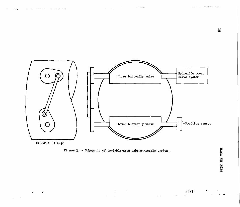
A sketchof thevariable-areaexhaust-nozzlesystemis shownin fig-ure1. It consistedof dualbutterflyvalvesmountedin thetailpipeabout9 feetdownstreamof theturbine.The shaftsof thetwovalveswereconnectedby a mechanicalcrossarm-typelinkage.Theuppershaftwasdrivenby thepowerstageof an electrohydraulicservosystem.Areavar-iationsfrom73 to 13.3percentof ratedareawereobtainablewiththissystem.Thisexhaust-nozzlesystemwas designedforfastresponsewith-outconsiderationof goodthrustcharacteristics.
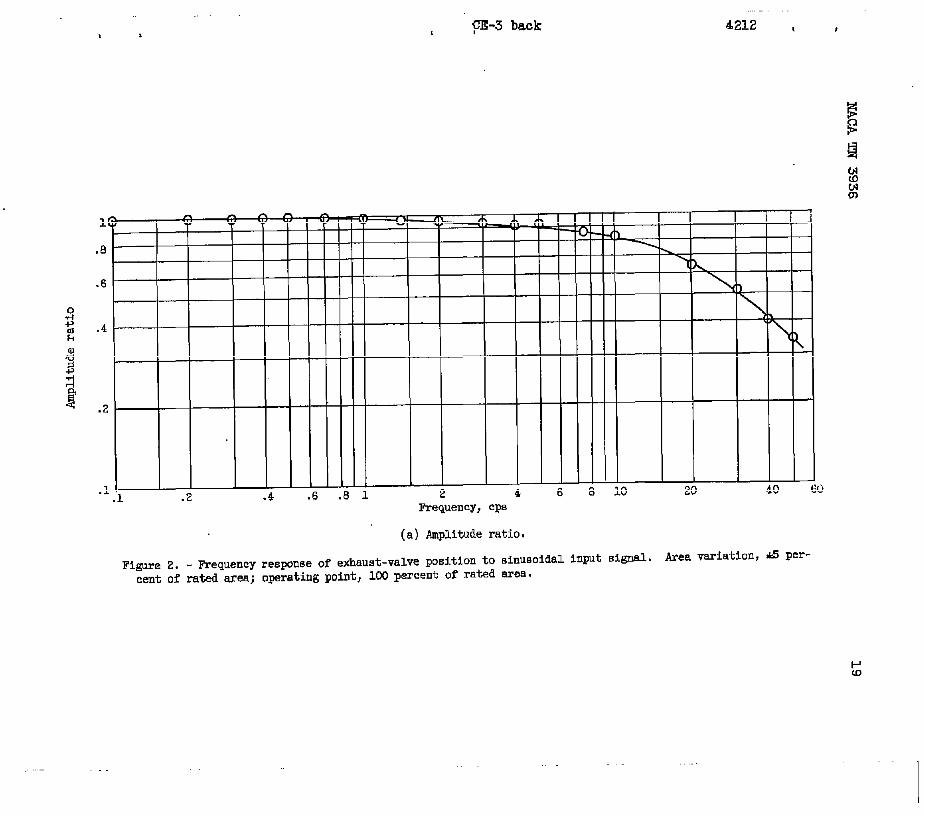
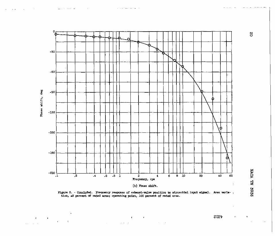
+Figure2
positionto a10percentof
showsthefrequencyresponseof the lowerbutterfly-valvesinusoidalinputsignalfora totalareaexcursionof aboutratedsrea.
Instrumentalion
~ Enginespeed.- To measureenginespeed,a magneticpickupwas in-2 stalledin the compressorhousingoppositea rowof steelcompressorrotorl-l blades. Eachbladepassingthepickupproduceda voltagepulsewhichwasA fedto an electroniccircuitwhoseoutputwas a voltageproportionalto.0 thenumberof pulsesper unittime. Thisvoltageprovideda goodindica-
tionof instantaneousenginespeedduringtransients,sincethepickupandelectroniccircuithadno measurabledynamicsin thefrequencyrange.of interest.
For steady-statespeedmeasur~ent,thepulsesfromthemagneticpickupwerefedto a digitalcounterwhichdeterminedanddisplayedactu-al enginerpmwhenthepropertimeintervalwas selectedforthe countingcycle.
Tailpipetemperature.- Fouxrakes,eachconsistingof fourchromel-alumelthermocouples,wereusedto measuretailpipegastemperatureduringtransients.Adjacentthermocoupleson eachrskewereconnectedin seriesto formeightpafrs. Fromoneto eightpairswereparalleledto providethe inputsignalto thetemperaturepreamplifier.
As a compromisebetweenfastresponseanddurability,22-gaugewirewas usedforthesethermocouples.Withthissizewire,thetimeconstantof thethermocoupleswas approximately0.3secondin theregionof opera-tionselectedforthe controlstudy.
Thermocoupleson twoadditionalrakes,similarto the onesjustde-scribed,wereconnectedto a self-balancingpotentiometerfor steady-statetemperaturemeasurement.
4 .L - NACATN 3936.
Fuelflow.- T& positiono~the throttlevalvein thefuelcontrolwasmeasuredby meansof a linearvariabledifferentialtransformer.Theresultingpositionsignalwasthebestobtainabl%lndicationof fuelflowduringtransients.Actualfuelflowintotheengineis affectedby thedynamicsof thefuelmanifoldandflowdividersbetweenthefuelvalveandtheengine.
A rotameterwa~ usedforsteady-statefuel-flowmeasurement.
Exhaust-=nozzlearea.- A rotaryvariabledifferentialtransformerwas usedto measurethepositionof the lowerbutterflyvalve. The sig-nalobtainedwasusedas an indicationof exhaust-nozzleareaduringtransients,althoughactualareadidnotvaryexactlylinearlywithposi-tionof thebutterflyvalves.
i%PM
For steady-stateareameasurementthepositionof the lowerbutter-flyvalvewas indicatedby a precisiondirect-currentmeterwhichmeas-uredthevoltageon the armof a linesrwire-woundpotentiometercon-nectedto the lowershaft. Accwrate&ureadeterminationcouldbe madebyusingthemeterreadingandan areacalibrationcurve.
Recording’equipment.- Transientdatawererecordedon a direct-writingsix-channeloscillographrecorder.Therecorderpens,whenusedwithequalizinga~lifiers,hada frequencyresponseessentiallyflatto100cyclesper second.A recorderchsr%peed of 25 millimetersper sec-ondwas used.
For sinusoidaldataa galvanometriclight-beamoscillographrecorderwas used. Flatfrequencyresponsebeyond100cyclesper second,highsensitivities,andhighchartspeedswereobtainablewiththisequipment.
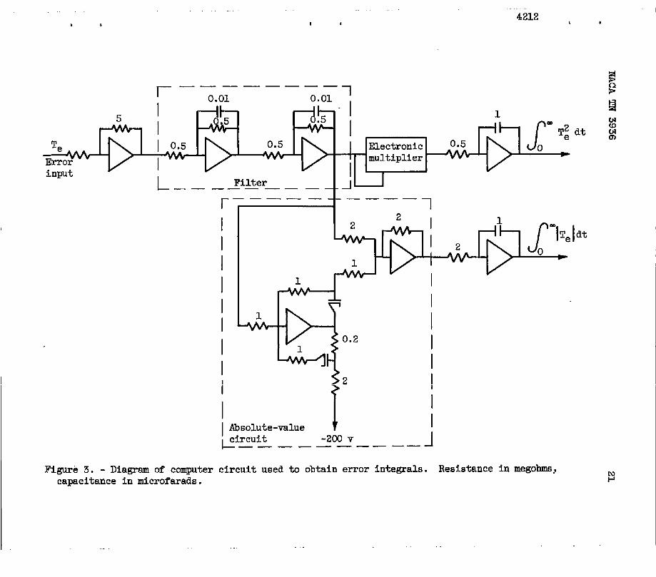
Analogcomputing-eqgi~ent.- CircuitsforcalculatingtimeIntegralsof thesquareandabsolutevalueof-temperatureeirorwerasetup usinglinearandnonlinearelementsof anelectronicanalogcomputer.These.circuitsareshownin figure3. A two-stageR-Cfilterwas usedto re-ducenoisein thetemperature-errorsignal.An electronicmultiplierper-formedthe squaringoperation.The integralvaluesobtainedwereusedinevaluatingtransientresponseof controlledtemperature,as willbe dis-cussedin the sectionControlledEngineData.
CONTROLSYSTEMS
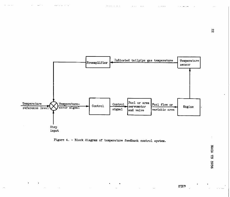
A blockdiagramrepresentativeof thebasictemperaturefeedbackcon-trolsystemsusedforthisinvestigationis shownin figure4. In these .systemstheindicatedtemperaturesignalwas comparedwiththedesiredtemperaturereferencelevel,andthedifferenceor ~ror signalwas appliedto theinputof thecontrol.The controlmodifiedthe errorsignalac- *cordingto thecontroltransferfunction.Theresultingcontrolsignal
NACATN 3936 5
was appliedto the inputof thefuelor sreaservosystem,whichchangedfuelflowor areauntilthetemperature-errorsignalbecamezero. Pro-visionfor stepchangein temperaturereferencelevelwas includedfortransientoperation.
Temperature- Fuel-FlowControl
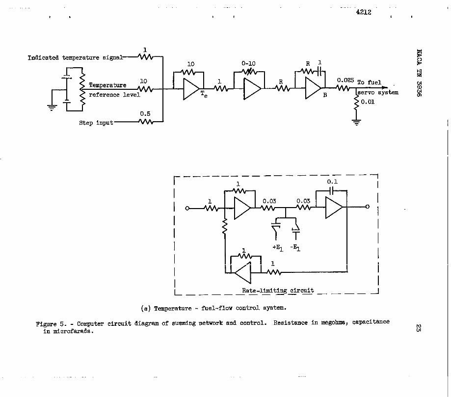
Thetemperaturesummingnetworkandcontrolcomponentsforthetemperature- fuel-flowcontrolsystemwereset--upon an electronicana-logcomputeras shownin the circuitdiagramof figure5(a). Controlgainandintegraltimeconstantcouldbe variedseparately.Alsoshownin figure5(a)is a rate–limitingcircuitthatwas insertedat pointBin the controlloopto limittherateof changeof fuelflow. The ef-fectsof slowerfuel-valveactionon control-loop-parameterselection ,willhe discussedin the section“Rate-limitedfuelcontrol.”
Temperature-AreaControl
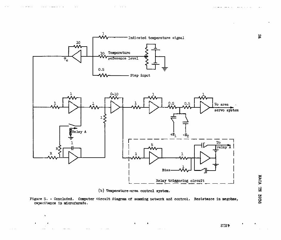
FigureS(b)showsthe computercircuitdiagramof thetemperaturesummingnetworkandcontrolcomponentsusedforthetemperature-areacontrolsystem.The controlcircuitryforthissystemwasmorecom-plexthanthatof thetemperature- fuel-flowcontrolsystem.Becauseof resultsencounteredin a previousspeed-areacontrol-systemstudy(ref.2),it was foundnecesssrytoaddnonlinesrcomponentsto the con-trol. Thesecomponentswerea diodelimiteron the inputto the areaservocontrol,anda relayandrelaytriggeringcircuit.
Duringthepreviousspeed-areacontrol-systemstudy(ref.2),it wasfoundthat,whenthe areabutterflyvalvesopenedto a positioncorre-spondingto approximately113percentof ratedarea,furtherincreaseininputsignalto theareaservosystemdidnot increasearea. Thiswasdueto the limitationon maximumareaobtainablewiththebutterflyvalvesfullyopen. Thus,whenoperatingwitha closed-loopsystemandaproportional-plus-integralcontrol,thecontroloutputsignalat timeswouldexceedthe areaservo-systeminputlevelcorrespondingto the satu-rationlimit(113percentratedarea). Whenthishappened,an excessivechargewouldbuildup on the integralcomponentof the control,whichdelayedthe closingof theareavalvewhenthe errorsignaldecreased,.Thisproducedpoorcontrolperformance,thatis, largeovershoots.
Forthetemperature-areacontrol-systemstudy,thebiasvoltagesofthe limiterdiodeswereadjustedto limit---theinputsignalto the areaservosystemto valuescorrespondingto approximately85 and 113percentof ratedarea. Themaximumareawas determinedby theparticulararea-valvedesignandtailpipethatwereused. Theminimumareawas arbitrar-ilychosen.
NACA’IN3936 *
Thebiasvoltageof’the relaytriggeringcircuitwasadjustedsothattherelayclosedwhentheinputsignalto theareaservomotorcontrol -decreasedbelowthevaluecorrespondingto 85 percentof ratedsrea.Closingtherelay,in effect,stoppedtheintegralactionof thecontrolby addingan equalbut opposite-signerrorsignalto the inputof thein-tegrator.A similartriggeringcircuitcouldhavebeenaddedto oneratetherelayat themaximumareastudybecausethe initialandtowardthe closedposition.
The experimentalprogram
limit-butwasnotdeemednecessaryf& thismaximumexcursionof theareavalveswas
PROCEDURE
consistedof (1]a determinationdynamicsin thehigh-speedregionof%perationand (2}a study
of engineof con-
trolledenginetransientresponseandcontrolstabilitylimitforthetwobasictemperaturefeedbackcontrolsystems.
Enginedynamicswereobtainedfromfrequency-responsedata. Sinu-soidalinputsignalswereappliedto thefuelcontrolandareacontrol,andresponsesof enginevariableswererecorded.Frequency-responseplotsweremadeandanalyticaltransferfunctions,madeup of engineandinstrumentationdynamics,werefittedto theseplots. .
The enginewas operatedon controlusingthesystemsshownin fig-ures4 and5. Stepinputswereappliedto increasethetemperatureref- .
erencelevelan amountequalto approximately7 percentof ratedtempera-ture. Controlgainandintegral_timeconstantwerevariedQvera rangeof values,andresponsesof enginevariableswere--recorded.Timeint%-gralsof the squareandabsolutevalueof.temperatureerrorwerecalcu-latedandrecorded.A rate-limitingcircuitwas addedto thetemperature- fuel-flowcontrolsystem,-andthe sae procedurefollowed.The stabilitylimitforbothcontrolsystemswasinvestigatedby increas-ingcontrolgainuntilthe systembecsmeandremainedoscillatory.
RESULTSANDDISCUSSION
EngineDynamics
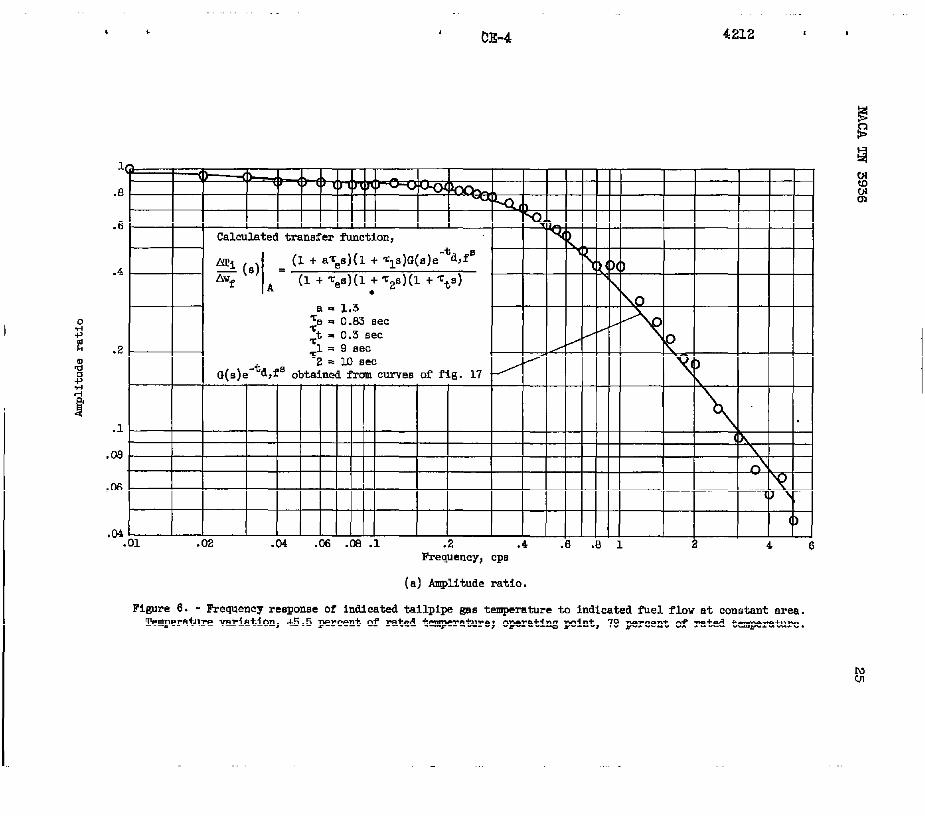
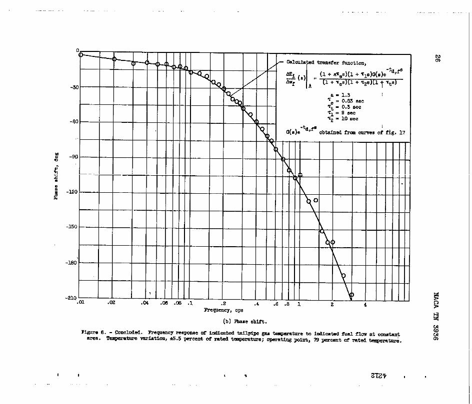
Responseof temperatureto fuelflow.- Experimentaldatarepresent-ingthe frequencyresponseof indicatedtailpipegastemperatureto indi-catedfuelflowat constantareaareshownin figu& 6. Thesedataweretakenin the ssmeregionof engineoperationas selectedforthecontrQlstudy. Thedatashownin figure6(a)andallsubsequentamplitude-ratio .datahavebeennortilized(thatis,theproductof allconstantgaintermshavebeensetequalto unity). .
NACATN 3936
Thenormalizedtemperature- fuel-flowtransf’eringto thedataof figure6 canbe representedby
7
functioncorrespond-
1where 1 + ‘c~s representsthethermocoupledynamics(symbolsarede-
‘td,fs:Q finedin appendixA),G(s)e representsthefuel-distribution-system* andcombustiondynsmics,andtheremainingtermsme includedin the actu-
al temperature- fuel-flowenginedynsmics.Combustiondynamics,usuallyconsideredpsrtof enginedynamics,couldnot easilybe separatedfromfuel-distribution-systemdynamicsbecauseof the difficultyof measuring
1 + Tlsactualfuelflowintothe engineduringtransients.Theterms ~ + =9E
&
wereincludedto representa longtime-constantphenomenonbelieveddueto a heating-expansioneffectin theturbinesection.Thisphenomenonhasusuallybeenneglectedinpreviousdynamicstudies.
.
.
.
In figure6 areshowncalculatedfrequency-responsecurvesof equa-tion(1). Numericalvaluesforthevsrioustermswereobtainedby graph-icalmethodsdescribedin appendixB.
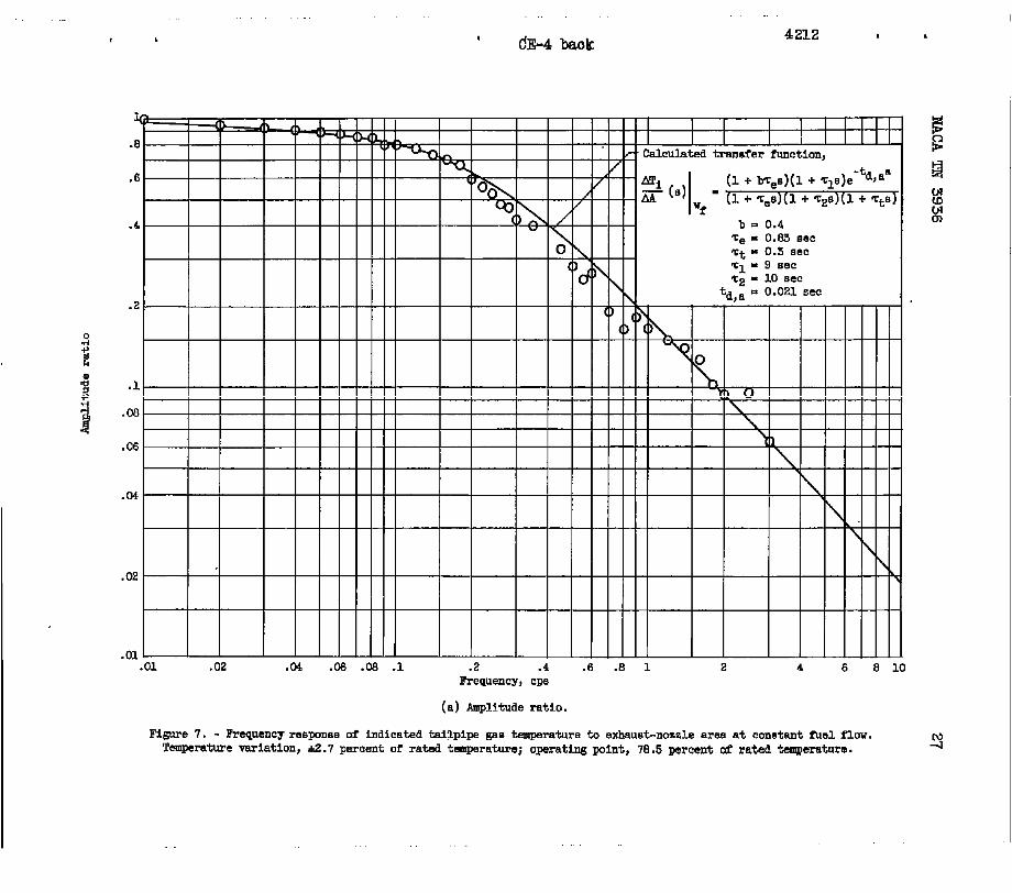
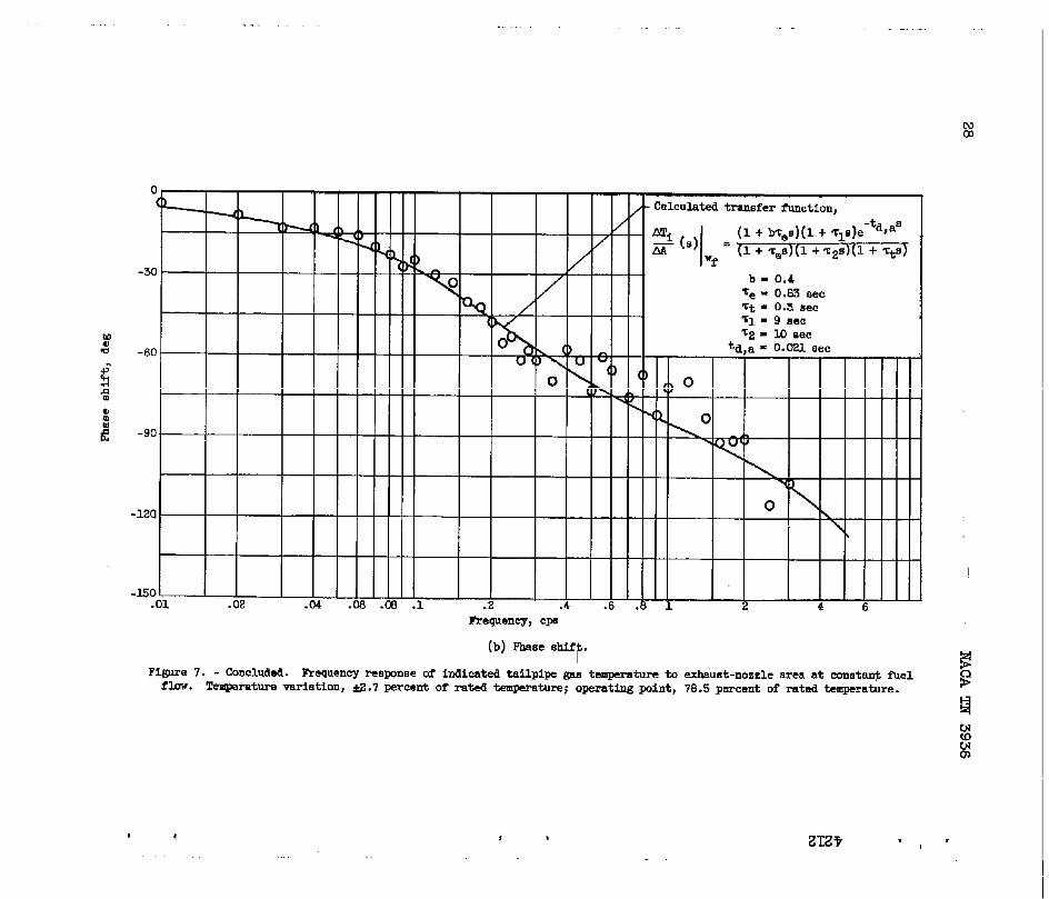
Responseof temperatureto area.- Figure7 showsdtiarepresentingthefrequencyresponseof indicatedtailpipegastemperatureto exhaust-nozzleareaat constantfuelflow. Theseexperimentaldatawerealsotakeninthe sameregionof engineoperationas selectedforthe controlstudy.
Thenormalizedtemperature-areatransferfunctioncorrespondingtothe dataof figure7 canbe representedby
(2)
Lwhere 1 -(-Tts representsthethermocoupledynamicsandthe remaining
termsrepresenttheactualtemperature-meaenginedynamics.Alsoin-cludedin thistransferfunctionarethetwo longtime-constanttermspreviouslymentioned.
Calculatedfrequency-responsecurvesof equation(2)arealsoshownin figure7. Numericalvaluesusedforthevsrioustermswerealsoob-tainedby graphicalmethodsdescribedin appendixB.
8 NACATN 3936.
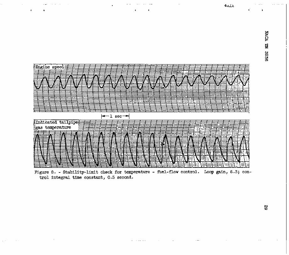
Stability-limitcheck.- Fromthefrequency-responseplots,predic-tionsof stabilitylimitsforthebasictemperaturefeedbackcontrolsys- -ternscanbe made. For thetemperature- fuel-flowcontrolsystem,thedatapresentedin figure6(b)indicatethata 170°to 180°phaseshiftoc-cursin the-frequencyrangeof 2.0to 2.2cycles~er second.Consideringnegligible.phaseshiftin thefuelsystemandlesg.than10°phaseshiftin the control(for ‘rC~ 0.5 see),a totalopen-loopphaseshiftof 180°wouldoccurin thissamefrequencyrange,2.0to 2.2cyclesper second.Fromtheamplitude-ratiodatapresentedin figure6(a),the loopgainatinstabilityshouldbe in therangeof 5.7to 6.9. For thisreport,loopgainis definedas theproductof allthefrequencyinvariantgainsaroundthe loop.
,-
itPN
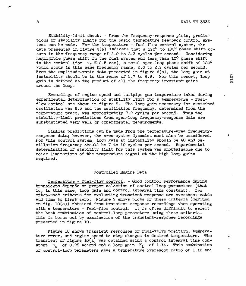
Recordingsof enginespeedandtailpipegastemperaturetakenduring .experimentaldeterminationof stabilitylimitfor.atemperature- fuel-flowcontrolareshownin figure8. The loopgainnecessaryforsustainedoscillationwas 6.3andthe oscillationfrequency,determinedfromthetemperaturetrace,was approximately2.2cyclesper second.Thusthestability-limitpredictionsfromopen-loopfrequency-responsedataaresubstantiatedverywellby experimental”measuremetis.
Similarpredictionscanbe madefromthetemperature-areafrequency-responsedat=jbnwever,thearea-systemdynamicsmustalsobe considered. &For thiscontrolsystem,loopgainat instabilityshouldbe 40 andos-cillationfrequencyshouldbe 7 to 10 cyclesper second.Experimentaldeterminationof stabilitylimitforthissystemwas unobtainableduetonoiselimitationsof thetemperaturesignalat thehighloopgainsrequired.
ControlledEngineData
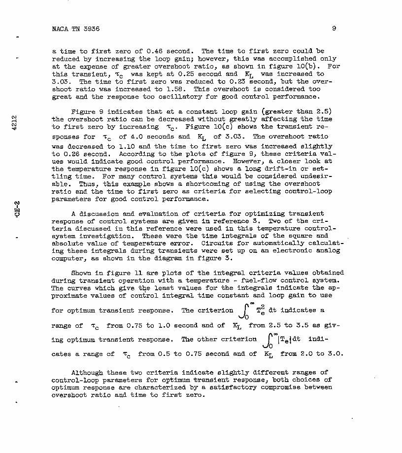
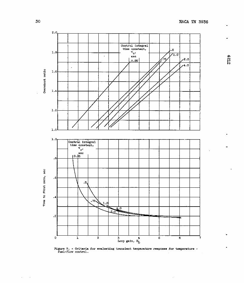
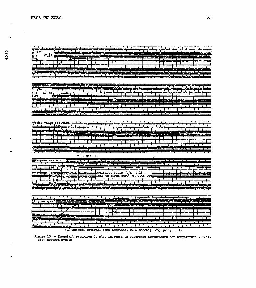
Temperature- fuel-flowcontrol.- Goodcontrolperformanceduringtransientsdependson properselectionof control-loopparameters(that1s,in thiscase,loopgainandcontrol.integraltimeconstant).Twooften-usedcriteriafor evaluatingtransientresponseareovershootratioandti~-to first-zero.Figure9 showsplotsof thesecriteria(definedon fig.10(a))obtainedfromtransient-responserecordingswhenoperatingwitha temperature- fuel-flowcontrol.It is oftendifficultto selectthebestcombinationof control-loopparametersusingthesecriteria.Thisisborneoutby examinationof thetransient-responserecordingspresentedin figure10.
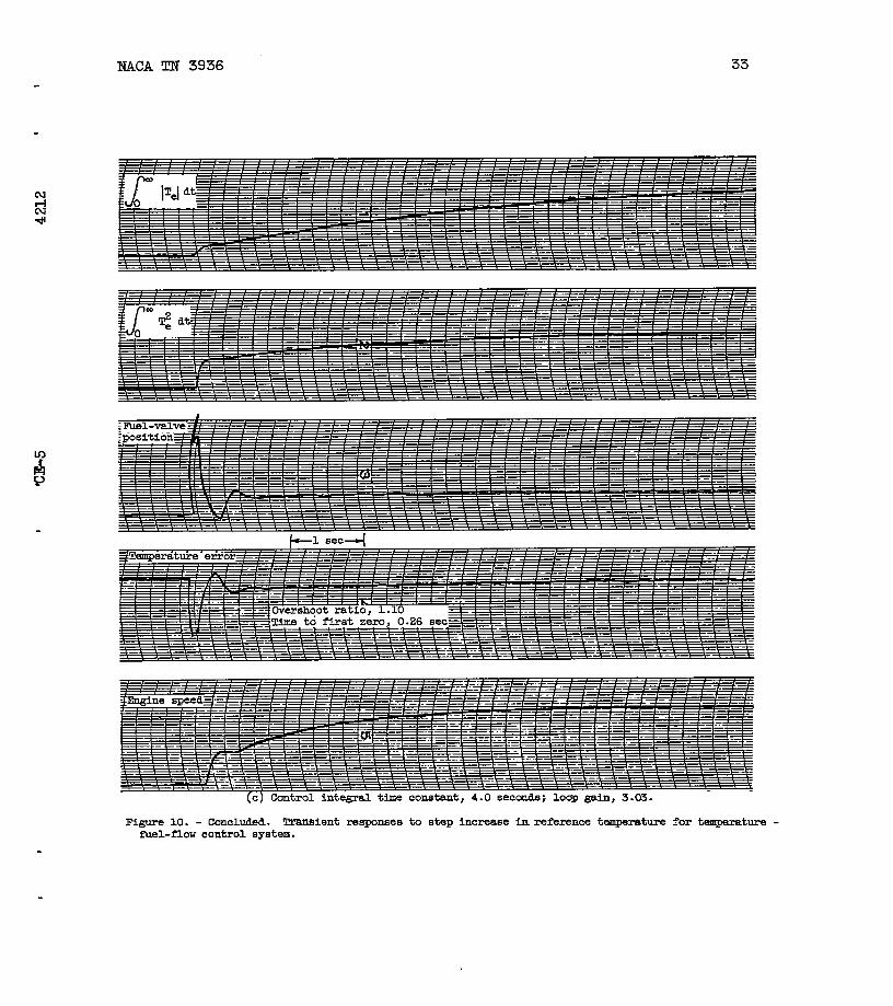
Figure10 showstransientresponsesof fuel-valveposition,tempera-tureerror,andenginespeedto stepchangesin desiredtemperat~e. The .transientof figure10(a)wasobtainedusinga controlintegraltimecon-stant Zc of 0.25secondanda loopgain KL of 1.14= Thiscombinationof control-loopparametersgavea temperatureovershootratioof 1.12and ,.
NAM TN 3936 9
.
.
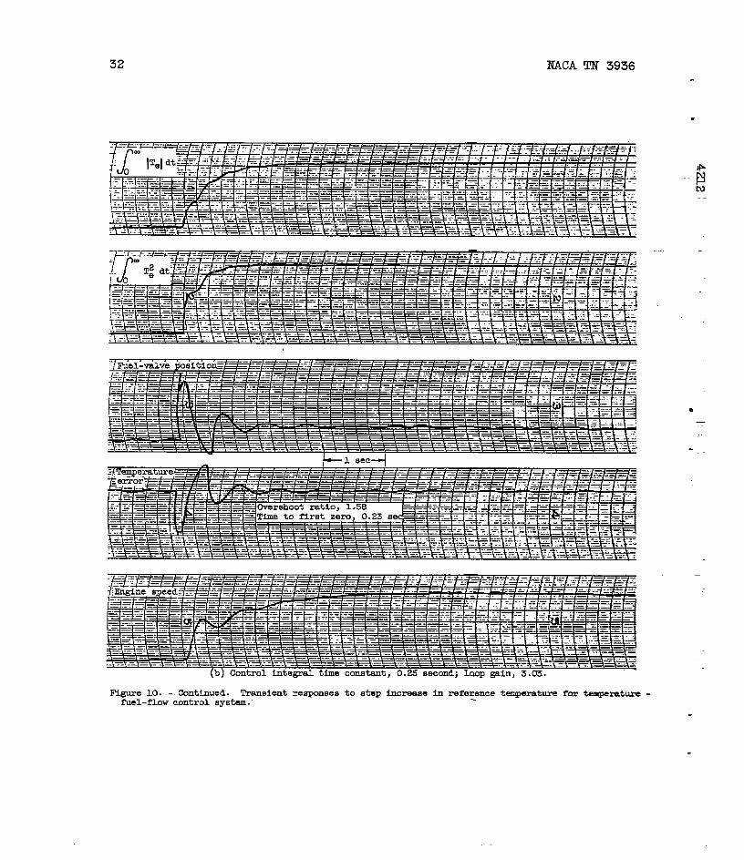
a timeto firstzeroof 0.46second.Thetimeto firstzerocouldbereducedby increasingthe loopgain;however,thiswas accomplishedonlyat theexpenseof greaterovershootratio,as shownin figure10(b).Forthistransient,Zc waskeptat 0.25secondand KL was increasedto3.03. Thetimeto firstzerowasreducedto 0.23second,but theover-shootratiowas increasedto 1.58. Thisovershootis consideredtoogreatandtheresponsetoooscillatoryforgoodcontrolperformance.
Figure9 indicatesthatat a constantloopgain(greaterthan2.5)the overshootratiocanbe decreasedwithoutgreatlytifectingthetimeto firstzeroby increasingZc. Figure10[c)showsthetransientre-sponsesfor Zc of 4.0 secondsand KL of 3.03. Theovershootratiowas decreasedto 1.10andthetimeto firstzerowas increasedslightlyto 0.26second.Accordingto theplotsof figure9, thesecriteriaval-ueswouldindicategoodcontrolperformance.However,a closerlookatthetemperatureresponsein figure1O(C)showsa longdrift-inor set-tlingtime. For manycontrolsystemsthiswouldbe consideredundesir-able. Thus,thisexampleshowsa shortcomingof usingthe overshootratioandthetimeto firstzeroas criteriaforselectingcontrol-loopparametersforgoodcontrolperformance.
A discussionandevaluationof criteriaforoptimizingtransientresponseof controlsystemsaregivenin reference3. Twoof the cri-teriadiscussedin thisreferencewereusedin thistemperaturecontrol-systeminvestigation.Thesewerethetimeintegralsof thesquareandabsolutevalueof temperatureerror. Circuitsforautomaticallycalculat-ingtheseintegralsduringtransientsweresetup on an electronicanalogcomputer,as shownin the diagramin figure3.
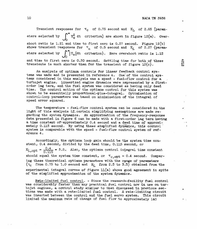
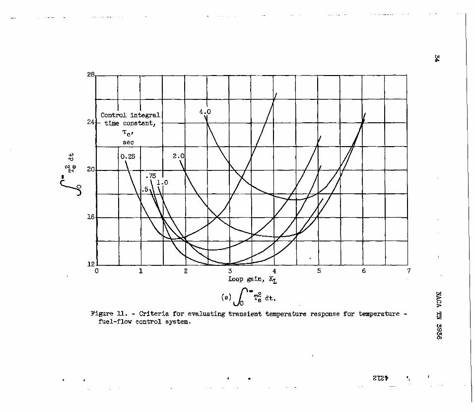
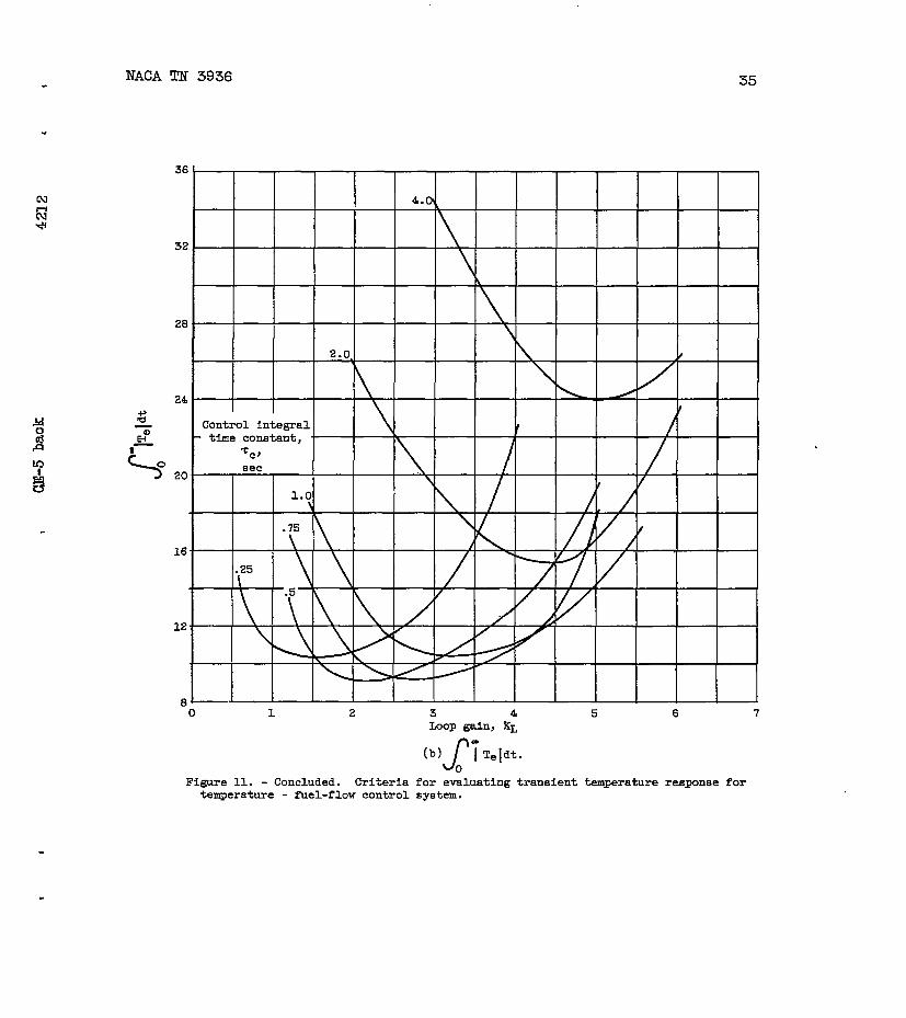
Shownin figure11 areplotsof theintegralcriteriavaluesobtainedduringtransientoperationwitha temperature- fuel-flowcontrolsystem.The curveswhichgivethe leastvaluesforthe integralsindicatethe ap-proximatevaluesof controlintegraltimeconstantandloopgainto use
foroptimumtransientresponse.The criterionJ
‘T2 dt indicatesaOe
rangeof ‘rCfrom0.75to 1.0secondandof KL from2.5to 3.5as giv-
ingoptimumtransientresponse.TheothercriterionJ
‘[Teldt indi-0
catesa rangeof Zc from0.5to 0.75secondandof KL from2.0to 3.0.
Althoughthesetwo criteriaindicateslightlydifferentrangesofcontrol-loopparametersforoptimumtransientresponse,bothchoicesofoptimumresponsearecharacterizedby a satisfactorycompromisebetweenovershootratioandtimeto firstzero.
10
Transient
etersselected
shootratiois
NACATN 3936
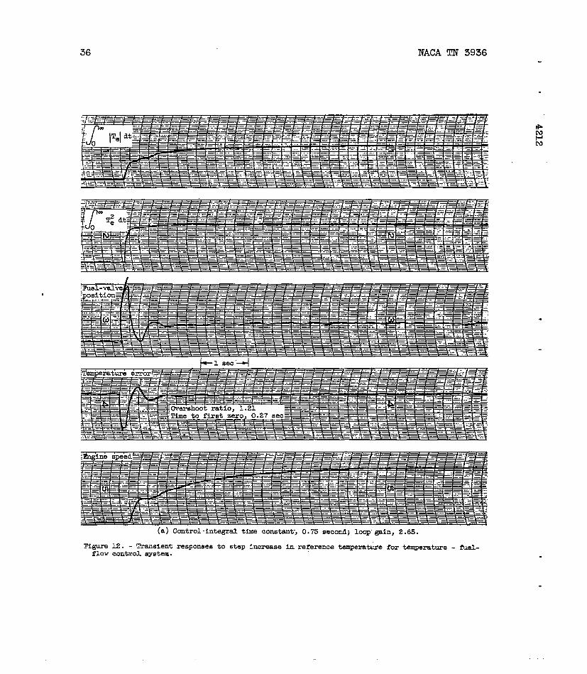
responsesfor ‘rC of 0.75secondand KL of 2.65~param- .
byJ
*2Te dt criterion)areshownIn figure12(a). Over-0
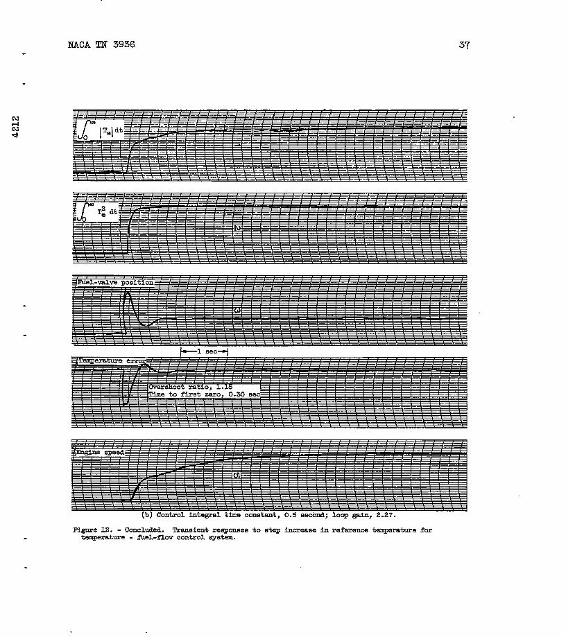
1.21andtimeto firstzerois 0.27”second.Figure12(b)showstransientresponsesfor ‘CC of 0.5secondand KL Of’2.27(ptiSm-
metersselectedby J’1 ITe dt criterion).Hereovershootratiois 1.15
0andtimeto firstzerois 0.30second.Settlingtimeforbothof thesetransientsismuchshorterthanforthetransientof figure1O(C).
An analysisof optimumcontrolsforlinearfeedbackcontrolsys-temswasmadeandis present%din reference. One-”ofthecontrolsys-temsconsideredin thisanalysiswas a speed- fuel-flowcontrolforaturbojetengine.Linearizedenginedynamicswererepresentedby a fi.rst-orderlag term, andthefuelsystemwas consideredas havingonlydeadtime. The controlactionof theoptimumcontrolforthissystemwasshownt-obe essentiallyproportional-plus-integral.Optimlzatlonofcontrol-loopparameterswasbasedon minimizationof theintegralofspeederrorsquared.
Thetemperature- fuel-flowcontrolsystemcanbe consideredin thelightof thisanalysisiflcertainsimplifyingassumptionsaremadere-
--
gardingthe systemdynamics.An approximationof thefreqhency-responsedatapresentedin figure6 canbe madewitha first-orderlagtermhavinga timeconstant-o~approximately0.4secondanda deadti”meof approxi-mately0.115second.“Byusingthese”simplified&namLcs,thi&control””systemis comparablewiththe speed- fuel-flowcontrolsystemof ref-erence4. .-
Accordingly,theoptimumloopgainshouldbe tbesystemtimecon-stant,0.4second,dividedby thedeadtime,0.1L5second,or
‘L,opt= 0“4 = 3.5. Also,theoptimumcontrolintegraltimeconstant0.115shouldequalthe systemtimeconstant,or ~c,opt= 0.4second.Compar-ingthesetheoreticaloptimumparameterswithther@ngeof parameters(’cCfrom0.75to 1.0secondand KL from2.5to 325)obtainedfromthe
experimentalintegralcurvesof figuren(a) showsgoodagreementin spiteof thesimplifiedapproximationof thesystemdyaamlcs.
Rate-limitedfuelcontrol.- Sincetheresearch-facilityfuelcontrolwas considerablyfasterthananypracticalfuelcontrolnowin useon tur-bojetengines,a controlstudysimilarto thatdisc~sedin previoussec-tionswasmadewitha rate-limitedfuelcontrol.A rate-lhd.tingcircuitwas insertedbetweenthe“controlandthefuelservosyst-em.Thiscircuitlimitedthemaximumrateof changeof fuelflowto approximately140
9s’m
NACATN 3936 11.
.percentof ratedfuelflowin 0.1second.Althoughthisratemaybegreaterthanthatof a practicalfuelcontrol,it was consideredsuffi-cientlylessthanthe originalrateto showtheeffectson controlper-fotianceof a slowerfuelcontrol.
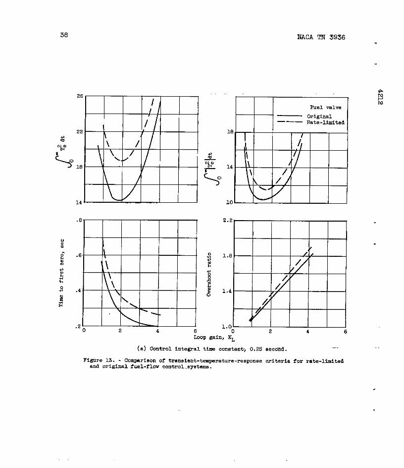
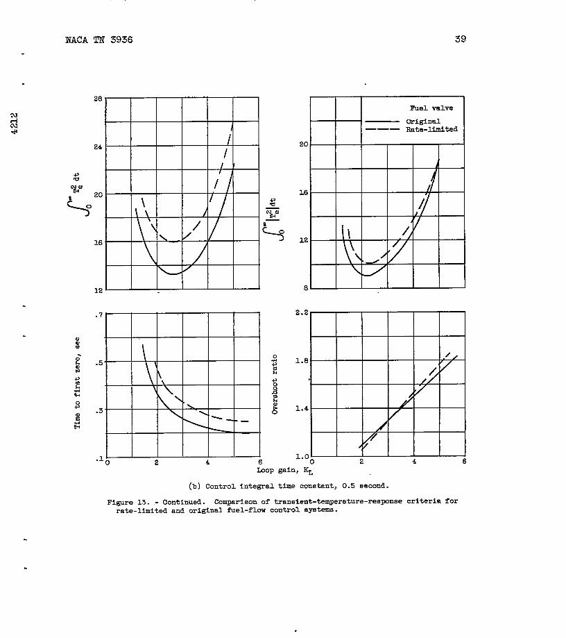
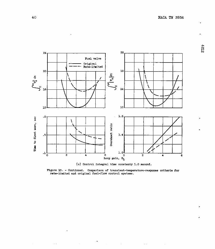
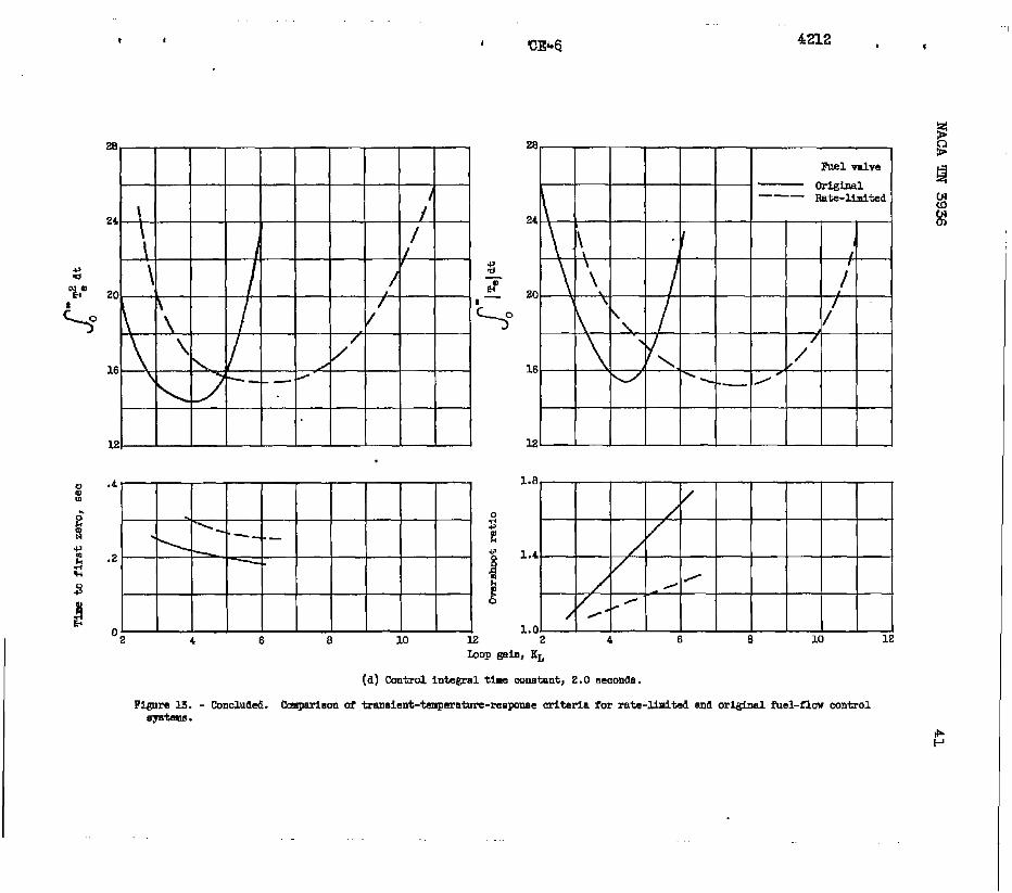
Figure13 showsplotscouparingintegrals,overshootratios,andtimesto firstzerofortheoriginalandrate-limitedfuelcontrol.Inte-gralcriteriavalueswerehigherfortherate-limitedfuelcontrol,butminimumsindicatedaboutthe samechoiceof controlintegraltimecon-stant’andloopgainforoptimumtransientresponse.Therate-limitedfuelcontrolgaveslightlygreatertimesto firstzerothanthe originalcontrol.At smallvaluesof %C therate-limitedcontrolgavemoretem-peratureovershootthanthe originalcontrol,andat largevaluesof Zctherate-limitedcontrolgavelesstemperatureovershootthanthe originalcontrol.The optimumtransientresponsefortherate-limitedfuelcontrolstillindicateda satisfactorycompromisebetweenovershootratioandtimeto firstzero.
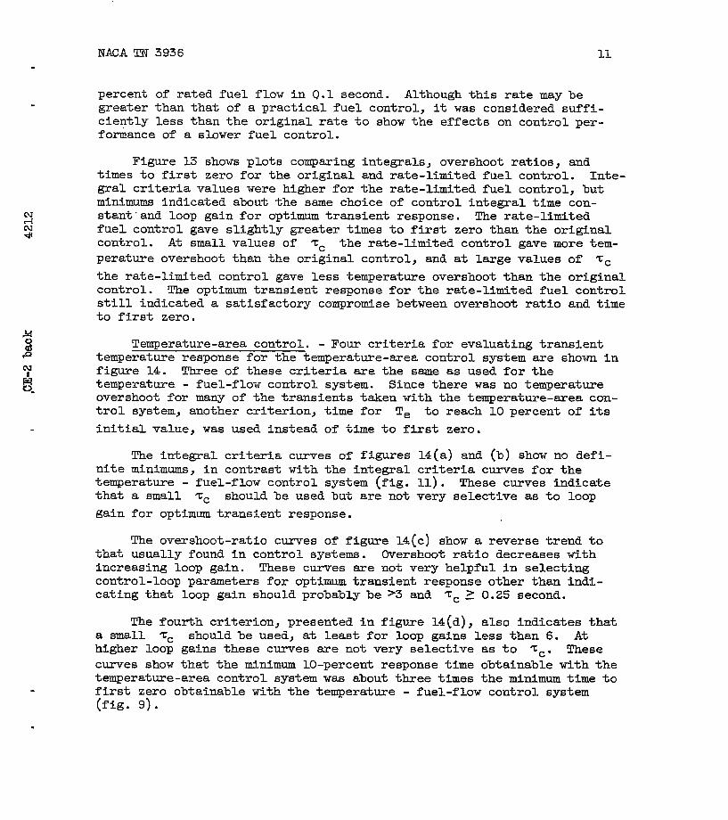
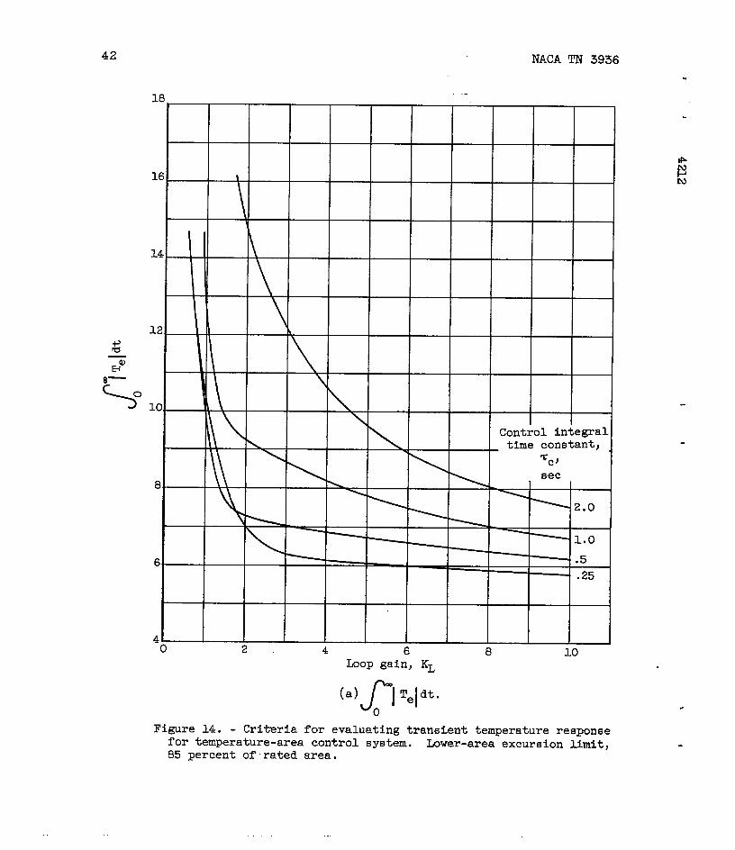
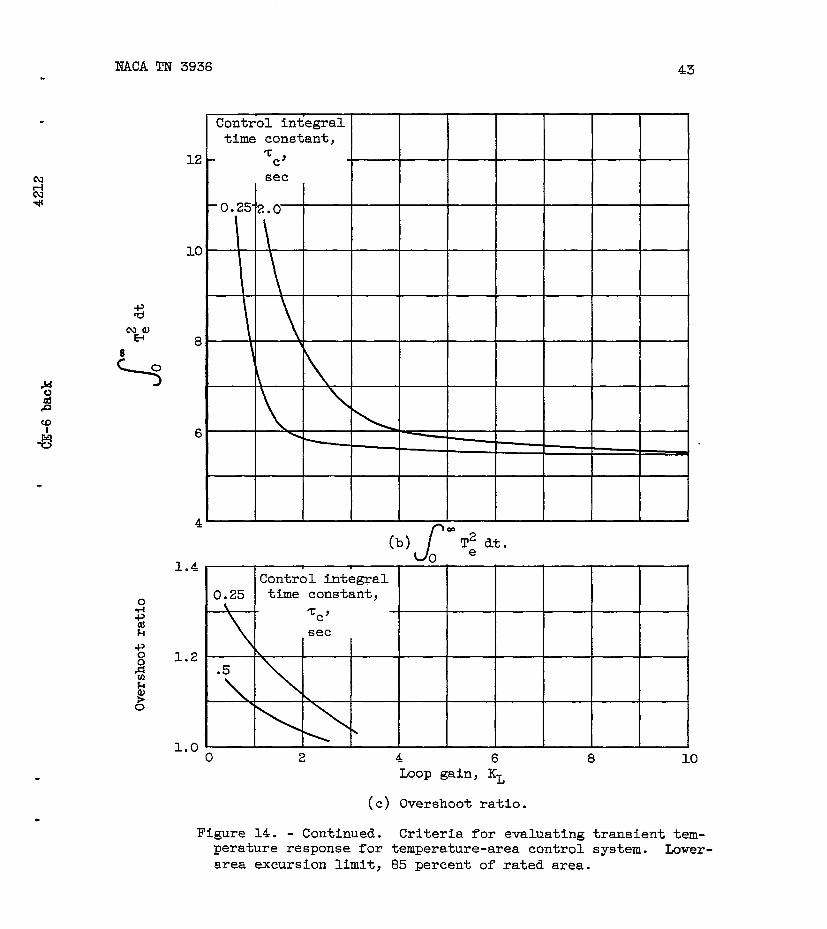
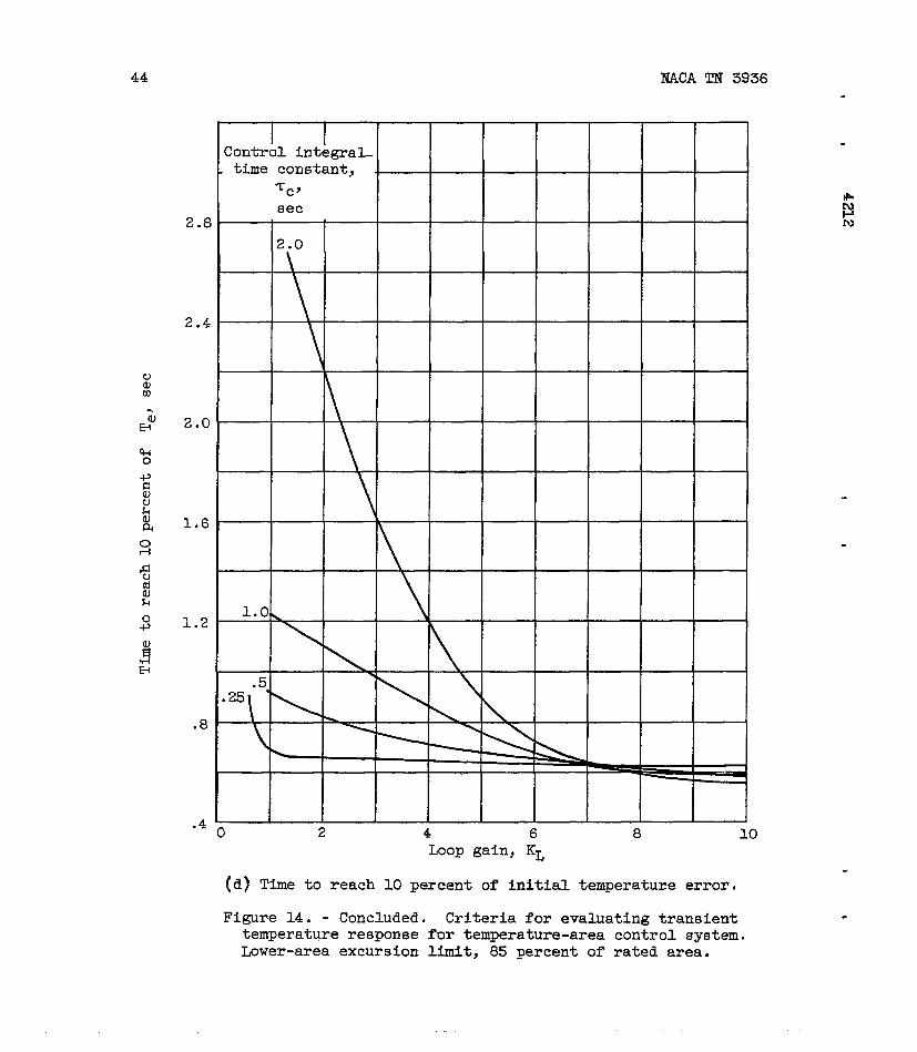
Temperature-areacontrol.- Fourcriteriaforevaluatingtransienttemperatureresponseforthetemperature-areacontrolsystemareshowninfigure14. Threeof thesecriteriaarethe sameas usedforthetemperature- fuel-flowcontrolsystem.Sincetherewasno temperatureovershootformanyof thetransientstakenwiththetemperature-sreacon-trolsystem,anothercriterion,timefor Te to reach10percentof itsinitialvalue,wasusedinsteadof timeto firstzero.
The integralcriteriacurvesof figures14(a)and (b)showno defi-niteminimums,in contrastwiththe integralcriteriacurvesforthetemperature- fuel-flowcontrolsystem(fig.11). Thesecurvesindicatethata small Zc shouldbe usedbutarenotveryselectiveas to loopgainforoptimumtransientresponse.
Theovershoot-ratiocurvesof figure14(c)showa reversetrendtothatusuallyfoundin controlsystems.Overshootratiodecreaseswithincreasingloopgain. Thesecurvesarenotveryhelpfulin selectingcontrol-loopparametersforoptimumtransientresponseotherthanindi-catingthatloopgainshouldprobablybe >3 and %C? 0.25second.
Thefourthcriterion,presentedin figure14(d),alsoindicatesthata small ‘c shouldbe used,at leastfor loopgainslessthan6. Athigherloopgainsthesecurvessrenotveryselectiveas to Zc. Thesecurvesshowthattheminimum10-percentresponsetimeobtainablewiththetemperature-areacontrolsystemwas aboutthreetimestheminimumtime tofirst zero obtainable with the temperature- fuel-flow control system(fig.9).
.

12 -. NACATN 3936
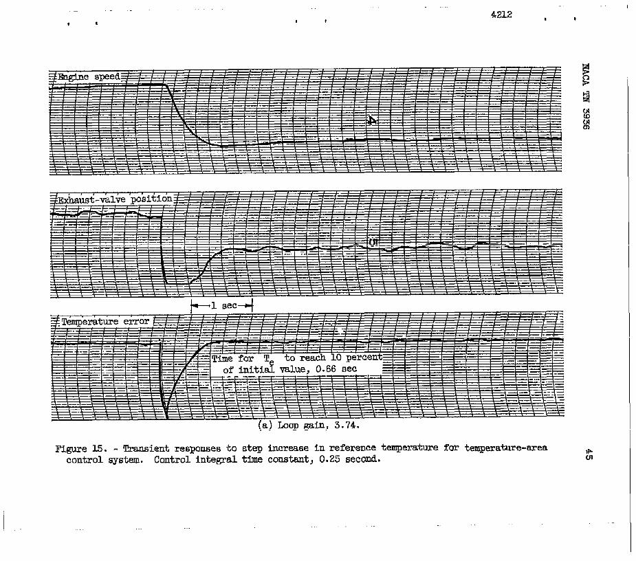
In figure15 areshowntransientresponsesof engine-speed,exhaust-valveposition,andtemperatureerrorforthetemperature-areacontrolsystem.To obtainthedesiredincreasein temperature,thecontrolclosedtheareavalves;butin thiscasethespeeddecreasedinsteadofincreasingas i&did withthetemperature- fuel-flowcontrolsystem(fig.12).
Figure15(a)showsthetransientresponsesfo~zc of 0.25secondand KL of 3.74. Thiscombinationof control-loopparametersgaveveryslighttemperatureandspeedovershoots.Thetimefor Te tu reach10perce~tof.itsinitialvalu~.was approximately0.66second.Theexhaust-valve-positiontraceshows“thatthesreaclosedquicklyandremainedatthe limitingposition(85percentof ratedarea)forapproximately0.4secondandthenopenedslowlyto the steady-statepositioncorrespondingto thefinaldesiredtemperature.
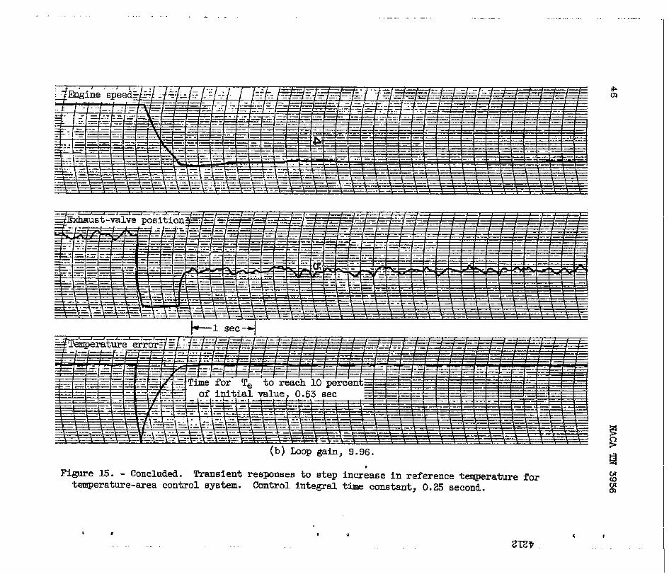
Transientresponsesfor ‘CC of 0.25secondand KL of 9.96areshownin figure15(b). Therewasno temperatureovershootandveryslightspeedovershoot.Thetimefor Te to reach10percentof itsinitialvaluewas apjioximately0.63second.Duri@ thistransient,theexhaustvalvesremainedat thelimitingpositionforapproximately0.58secondandthenvery“quicklyopenedto thefinalsteady-stateposition.
The10-percentresponsetimesobtainedfromthetransientdataoffigure15 do notclearlyindicatea choice‘ofiloopgain;bu~consideringthe-sreatraces,it wouldbe preferableto usethelowervalueof loopgain. At thehigherloopgaintheareavalveismoresensitiveto thenoisein the–temperaturesignal.
CONCLUDINGREMARK6
In thehigh-speedoperatingregion,tailpipegastemperaturecouldbe satisfactorilycontrolledduringsmalltransientsby usingtemperaturefeedbackcontrolsystemswhichvariedeitherfuelflowor exhaust-nozzlearea. A proportional-plus-integralcontrolin a temperature- fuel-flowcontrolsystemprovidedsatisfactorytransientresponseto a desiredstepincreasein temperature.For a temperature-areacontrolsystem,it wasnecessaryto addnonlinearcomponentsto thebasicproportional-plus-integralcontrolto providesatisfactorytemperatureresponseduringtransients.
For theessentially
errorfunctionintegrals
is thetemperatureerror
lineartemperature- fuel-flowcontrolsystem,
J’ Jll
w
suchas = T: dt and Te dt (whereTeo 0
and t is time)appearedto be bettercriteria
NACATN 3936 13
thanovershootratioandtimeto firstzerofor selectingcontrol-loopparametersforoptimumtransienttemperatureresponse.Control-loopparametersselectedon thebasisof theseintegralcriteriaagreedverywellwith‘optimumpredictionsof a previousanalysis..
Limitingtherateof changeof fuelflowdidnotappreciablyalterthe selectionof control-loopparametersforoptimumtransienttempera-tureresponse.
Forthetemperature-areacontrolsystem,whichis nonlinearbecauseof areasaturationlimits,theintegralcriteria,theovershootratio,andthetimefor Te to reach10percentof itsinitialvalueweresome-whatinadequatefor selectingloopgainforoptimumtransienttemperatureresponse.However,thesecriteriadid indicate that a small control inte-gral time constant shouldbe used.
Thetransferfunctionsgivenby equations(1)and (2)providedasatisfactorydescriptionof engineandinstrumentationdynamicsin thehigh-speedoperatingregion.
LewisFlightPropulsionLaboratoryNationalAdvisoryCommitteeforAeronautics
Cleveland,Ohio,January18,1957
14 — IW3ATN3936
APPENDIXA
SYMBOLS
A
a
b
E
G(s)
KL
‘L,opt
N
s
Te
Ti
t
‘d,a
‘d,f
Wf
‘c
‘C,opt
‘e
Tt
T1
‘C2
exhaust-nozzlearea,sq In.
initialriseratioof temperatureto stepchangein fuelflowat constantarea
initialriseratioof temperatureto stepchangein areaatconstantfuelflow
voltage .
transferfunction
loopgain,productof-frequencyinvariantgainsaround10UP
optimumloopgain
enginespeed,rpm
complexvariableusedin Laplacetransformationmethods
errorbetween.indicatedandreferencet~mperaturesl‘F
indicatedtailpipegastemperature,W
time,sec
deadtimeof temperatureor speedto area,sec
deadtimeof temperatureor speedto fuelflow,sec
indicatedfuelflow(afuel-valveposition),lb/hr
controlintegraltimeconstant>sec
optimumcontrolintegraltimeconstant,sec
enginetimeconstant,sec
thermocotipletimeconstant,sec
timeconstantof a leadtermof enginedynsmics,sec
timeconstantofa lagtermof enginedynamics,sec
NMATN3936 15
APP~IX B
MRTHODOF OBTAININGENGINE
FREQUENCY-RESPONSE
DYNAMICSFROM
DATA
Graphicalmethodscanbe appliedto the speedandtemperaturefrequency-responsedatato evaluatethevarioustimeconstants,deadtimes,andinitialriseratiosof equations(1)and (.2).Thesemethods,whichwillbe describedin thisappendix,arebaseduponthemanipulationof varioustransferfunctions.Derivationof transferfunctionsdescrib-ingenginedynamicbehaviorcanbe foundin reference5.
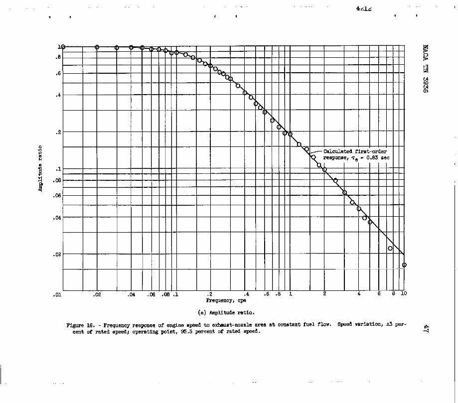
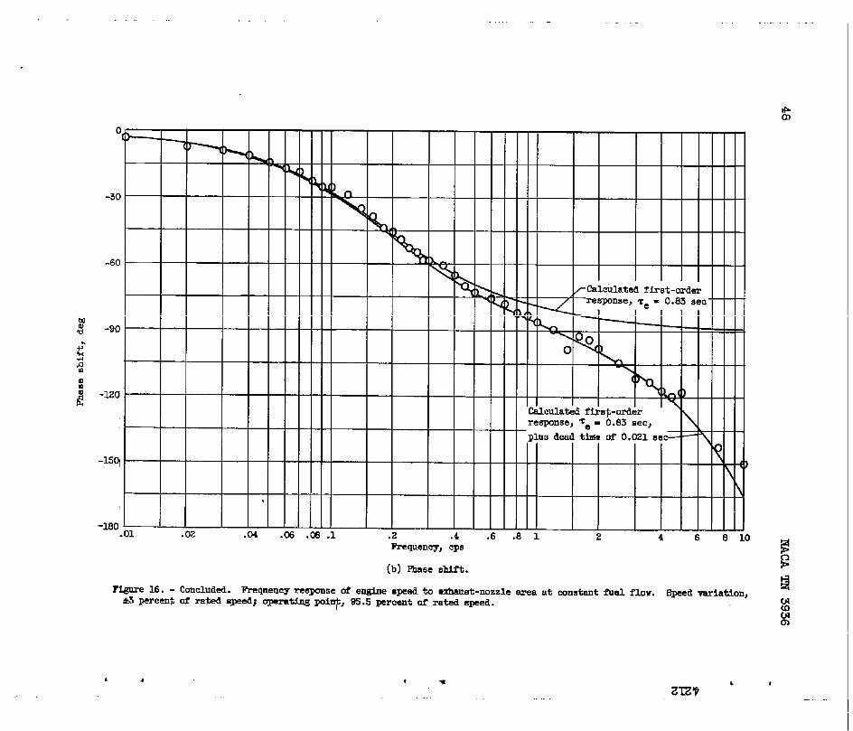
The enginetimeconstantcanbe obtainedfromthe speed-areafrequency-r=sponsefunction-ofe&inecanbe represented
datashownin figure16. Thenormali&dtransferspeedto exhaust-nozzleareaat constantfuelflowby
~ (s)e-td,as
a Wf = l+zes(Bl)
By fittinga first-orderresponsecurveto the experimentaldatain fig-ure16(a),an enginetimeconstantof 0.83secondwas determined.Also,by consideringthedifferencebetweenthe e~erimentaldataandthefirst-orderphase-shiftcurvein figure16(b),a speed-areadeadtimeof 0.021secondwas determined.
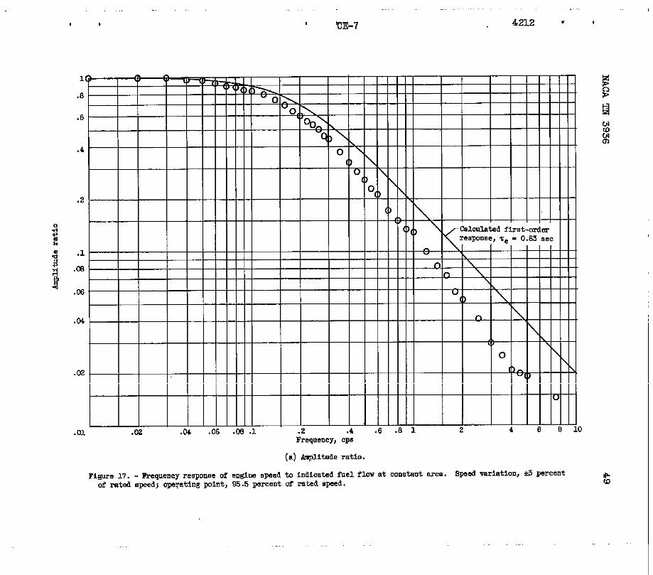
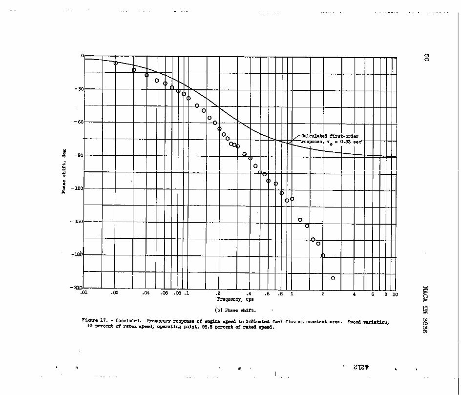
‘Thenormalizedtransferfunctionof enginespeedto indicatedfuelflowat constantareacanbe representedby
I-t~,&
~— (s] = G(s)eAwf A 1 + Tes
Experimentaldatarepresentingthe speed- fuel-flowfrequencyresponseareshownin figure17. Alsoshownin thisfigurearecalculatedfirst-
.Lorderresponsecurvesof 1 + ‘res with Ze = 0.83second.The differ-
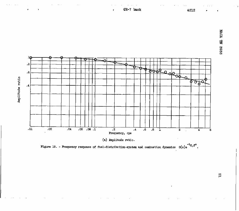
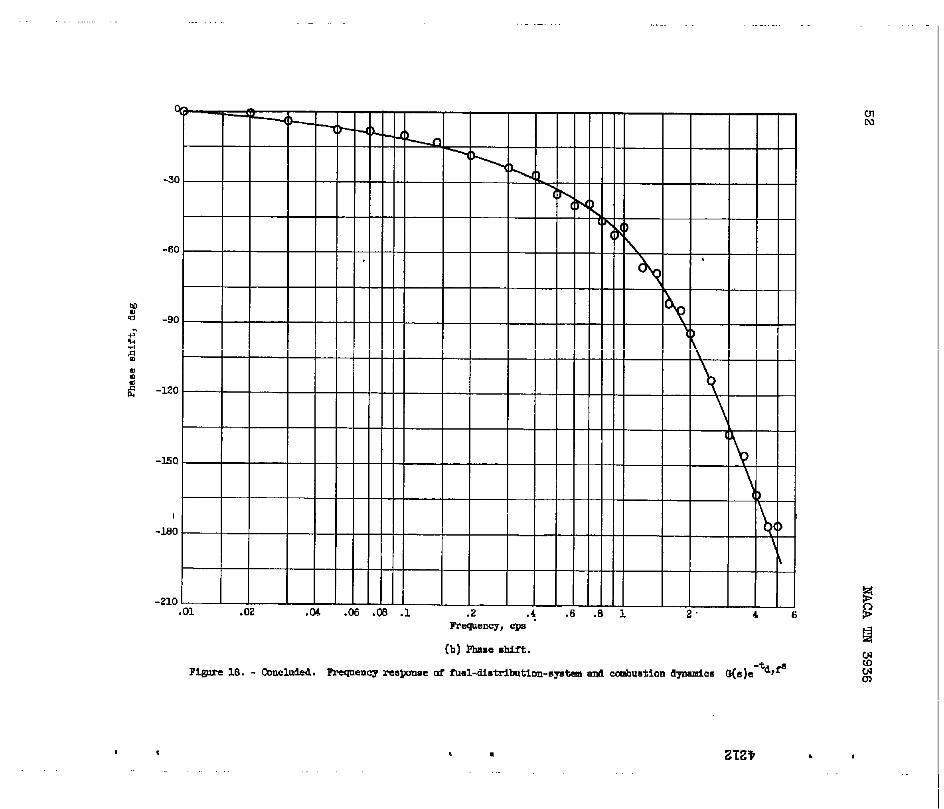
encebetweentheseresponsecurvesandthe experimentaldatarepresents-t s
G(s)e “f , thefuel-distribution-systemandcombustiondynamics.Plotsof thesedynamicsareshownin figureU3.
.
ture“
Thenormalizedtransferfunctionof indicatedtailpipegastempera-to indicatedfuelflowat constantareacanbe representedby
16
Dividingequation:
. NAUA ‘XN3YJb -—.
-%,+(1 + a~es)(l + Tls)G(s)e-~ (s) ~= (1 + Tes)(l 1-72s )(1+Tts}
(1) -
equation(1)by equation(B2)resultsin thefollowing
(1 + a~es)(1 + ‘rls)~ (s) =
A (1 + Tts)(l +“T2S)
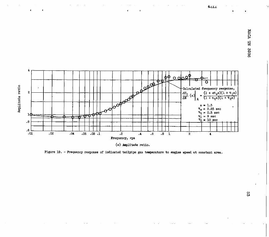
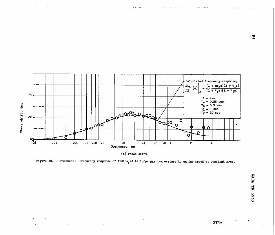
Datacorrespondingto equation(B3)canbe calculatedfromthe experi-mentaldataof figures6 and17. Plotsof thesecalculateddataareshownin figure19. Alsoshownin figure19 are_@culatedfrequency-responsecurvesrepresentingequation(B3). Numericalvaluesfortheriseratioandtimeconstantswerechosento make‘theresponsecurvesfitthe datawithreasonableaccuracy.Thusvaluesforinitialriseratio a of 1.3andforthermocoupletimeconstaiit~t of 0.3secondweredetermined.Timeconstantsof 9 andl.Gsecotidawereusedfortheotherleadandlagtermsof theenginedynamics.
Thenormalizedtransferfunctionof indicatedtailpipe gastempera-tureto exhaust-nozzleareaat constantfuelflowcanbe representidby .
(2) -
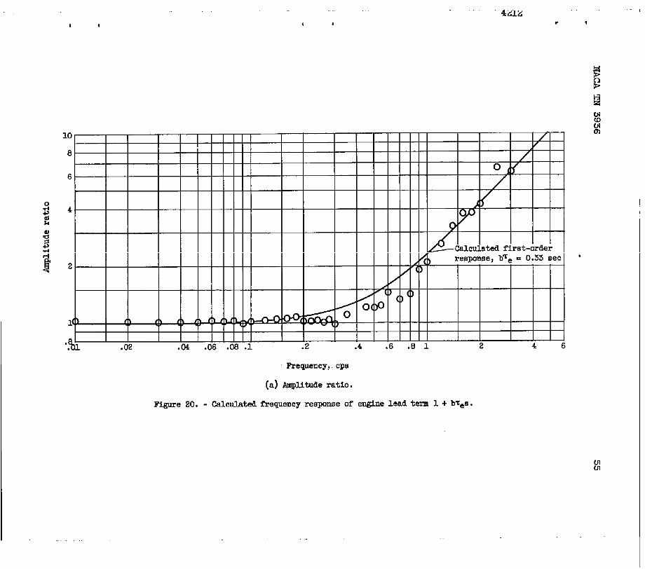
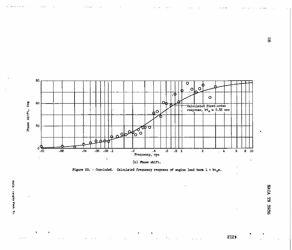
The deadtimeandallthetimeconstantsof thistransferfunctionhavebeendeterminedby themethodsdescribedin thep&cedingparagraphs.Thus,by extractingtheproducto~all thetermsexcept 1 + b~es fromthe datacorrespondingto thistransferfunction(fig.7),plotsof1 + b~es wereobtained.Theseplot=areshownin figure20. By fittinga first-orderresponsecurveto thesecalculateddata,a valuefortheinitialriseratio b of approximately0.4was determined.
Thenumericalvalues of thetimeconstants, deadtime, and initialrise ratios determinedby the methodsdescribedin this appendixarevalid in the range of operationwherethe frequewy-~esponsedata wereobtained. Since these values vsry with operatingrange, a morecompletedescription of enginedynamicscould be obtainedfromfrequency-responsedata taken at several operatingpoints.
.NACATN 3936 17
1.
2.
3.
4.
5.
REFERENCES
Otto,EdwardW., Gold,Harold,and.Hiller,Hrby W.: Designformanceof Throttle-TypeFuelControlsforEngineDynamicNACATN 3445,1955.
Wenzel,L. M.,Hart,C. E., andCraig, R. T.: comparison of’
Fuel-FlowandSpeed-&eaControlson a TurbojetEngineforStepDisturbances.NACATN 3926,1957.
andPer-Studies.
Speed-Small
Graham,FrankD.,andLatbrop,RichsrdC.: Synthesisof “Optimum”TransientResponse- CriteriaandStandardForms. WAIXTech.Rep.No. 53-66,WrightAirDev.Center,~r Res.andDev.Co_nd,Wright-PattersonAirForceBase,Aug.1953. @lONO. 206-11.)
Boksenbom,AaronS.,Novik,David,andHeppler,Herbert:OptimumControllersforLinearClosed-LoopSystems.NACATN 2939,1953.
Delio,GeneJ.: Raluationof ThreeMethodsforDeterminingDynamicCharacteristicsof a TurbojetEngine.NACATN 2634,1952.
.
.
-. . .— .
Cro6sarmllnksge
HydraulicpmerUpperbutterflyvalva
~’it’o”’en’orFi@re 1. - Schematicof variable-areaexhaust-nozzlesystem.
, .2-R* ‘ ‘
$31’-3baok 4212 , ,
FigureZ. - FrequencyCentOf rSted =eaj
Frequency,Cpa
(a)Amplituderatio.
respmse of exhaust-valmpositionto 6inusoldSliUpUtEi@. Mea ~iation, A Per-operatingpoint,103percentof ratedarea.
.- .—
.
g
~-
:
0
i-
.1 .2 .4 .6 .8 1 2 4 6 s 10 20 40 60Requency,CPM
(b)Ea.%@.shift.
F@ra 2.- Cmmluded . Frequmcyrmpmne ofexkmt-mlvepaitkm b sinui30iMinplt0iE8sl.Areamrti-,tiotl,& plwmt ofr@ellm; upmmingpint,1C4)peraentofIwt&larea.
, m!%’ t *,!
,4212 , ,
r —— —— ——— —0.01 0.01
II5 (!!5
-“1 1
Te j 0,5 Electronic 0“5
r“’”-multiplier
inputL__ –-zIEeL––_- .,J 1
Figure3. - Diagramofcomputercapacitanceinmlcrofarads.
~..—— — +————.I
I
22 I 1
12
1
*
*
1
11
IAbsOlute-value
0.2 II
2
‘Cfrcutt1-
-200v——— ——— —— —— 1
circuitusedto obtainerrorIntegrals.Resistanceinmegohms,
.
IvN)
===’(
I
Temperature-error signal *
Indicatedtailpipe gas temperature Temperaturesensor
I I I
Fuel flow or
variablearea
LIhgim
Stepinput
Figure 4. - Block diagram of temperaturefeedback control By-stem.
. ,
, , ,4212 , ,
1Indicatedtemperaturesignal~ B
10 0-1o R1 s
fi~
Q
!Cemperature10 w
referencelevel ;
~0.5
Step input =
___— ——— ——— —— ——— — —— 1
Figure 5. - Computerin microfarads.
O-&
I
1
-’l -
(e) Temperature- fuel-flow controlsystem.
circuitdiagramof aummlngnetworkand control. ResistanceIn megohms, capacitance
A--- Indicatedtemperaturesigoal10
10 Temperature
Te referencelevel
El0.5 ~
.L
_d ‘
rRetiy A-’
R 11
R
Figure5. - Concluded. Computercapacitsmcein mlcrofarads.
.
0-1o
DA&-l Al
1 To area
servosystem
I +El -E2-.—— ——— ——— ——— ——
I IRelay triggeringcticuit
L——— ———— ——. . . -J
(b) Tam~ature-area control.syatem.
circuitdiagramof sting networkand control. Resistancein megohms,
I
W4
Q *# .+
.8 b n n xI==e=GW ~ — ‘ — –
\
.6Calculatedtransferfunction,
t1
i
.4
FH
g! (s)
f
(1+ aTeE](I.+~ls)@s)e-td)fB
A= (1+ Te6)(l+ ~2s)(l+~~d
●
a n 1,3~s E 0.63sec m,+ - 0.5sec
.2 - # = 9 sec / ‘Z=losec
~(s)e-td,faobtainedfromcurvesof fig.17/
.1
,09
,06
.04.01 .02 .C-4 .C6.ml.1 .2 .4 .6
4212 ‘ ‘
Frequency,CPE
(a)Ar@ituderatio.
Figure6. - Frequencyre6pon8eof indicatedtailpipegastemperatureto indicatedfuelflowat condantarea.Temperaturevariation,&.5 percentof ratedteraperaturejoperatingpoint,79 percentof ratedtemperature.
tom
.—
-3(
-6(
~ -9[
$■
~ -~,
-m
-MO
-210
1 t ZRV , .
, (h-4 baok 4212 I .
.01 .02 .W .0s.m .1 .2 .4 .6 .8 1 2 4 6 8 10Frequancy, CPB
(a)Amplltuderatio.
[email protected] fiequenc~rtqome ml indicatedtailpipsgastemperaturetiexhaust-nozzl.aareaat conetantfuelflnw,l@er&3UY V’Uiatinn,M.7 peroentof rated t~rU~j opsratingpnint,78,5percent,tirated~eratll~.
, , , I 1
0
-3
-E
-ls
?requency,Wdl
(b)Phasesbifr“
Figure7. - C0nclude3.Frequencyre.swseof indicatedtailpipegast~ture toexhaunt-nomleareaat [email protected] varifltion,H.7 percentofratedtempsratum;operatingpoint,78.5percent of mted temperature.
. r
, 1
.-
, ,
t--l see-l
Figure El.- Stability-1imitcheckfortemperature- f’uel-flovcontrol.Loopgain,6.3;con-trolIntegralttieconstaut,0.5seccmd.
NACATN 3936
2.0.
G3ntrolintegraltimeconstant,
1.8.,.5
~c)sec /1.0
.0.25 2.04.0
~‘P 1.6 /6!.!
/
+0
3 /m / /
i 1.4 / /
/
/
/
1.2
/
1.o-
11.0 8 1Central Integraltimeconstant,
sec
.8
I
.6
\
.4\
\
.2
0 1 2 3 4 5 6 i’Loopgain,KL
.
.
.
.
.Figure 9. - Criteriaforevaluatingtransienttemperatureresponsefortemperature-fuel-flowcontrol.
NACATN 3936 31
.
mlA2
(a)ControlIntegral.the wnstant,0.25second;loopgain,1.14.
I!lgure10.- !&armientresponsestostepIncreaaeinreferencetemperaturefortemperature- fuel-flowcontrolsystem.
32 NACATN 3936.
●
—
Fi&yre10.- Continued.Transientre~eee tostepinfreaseinreferencetemperaturefortemperature-fuel-flowcontrolsystem.
.
.
NACATN 3936 33
.
03d$
Figure 10.- Ccm?huied. !3Ycankientresponsesta stapincrease5nreferencetemperaturefortemperature-fuel-flowcontrolsystem.
. .
2R
I,
Controlintsgral 4.0
Z4- time constat, 6
Te,
Sec /1
: 0.25 2.0 /
cdHal 20 \ / f io .75
\o
1.0,5, /
\ //
16./\
/
12:0 1 2 3 4 5 6 7
LOOP gain,KL
(a)J
‘~ dt.
Figure11.- Criteriaforewluatingtraneienttemperatureresponsefortemperature-fuel-flowcontrolByatem.
Z-R? *,
CJl
$m
NACATN 3936 35
.
36
4.0!
32
28\
24
Controlinte~altimeconetant, t / ‘
~c)
/1.0
/ :/.?
/ ‘
I.25\ I \l \l I 1/1 I 7r/ /
20 sec I \l /1 II I I I 1
Figure11.- Concluded.Criteriaforevaluatingtranaienttemperatureresponsefortemperature- fuel-flowcontrolsystem.
36 NACATN 3936.
(a)Control-integral.timeconetant-,0.75second;loopgain,2.65.
FYgure12.- Transientresponeeetostepincreaseinreferencetemperat&efortemperature- fueLflowcontrolsystem.
.
.
.
NACATN 3936 37
Cul-lNd+
(b)Controlintegralthusconstant,0.5~tij loop gain, 2.27.
i?lgureE. - Concluded.mansientreeponeestostepincreaseinreferencetemperaturefortemperature- fuel-flowcontrolsystem.
38 NACATN 3936
;ak
II Puel valve ]m — Original‘—— Rate-limitedI
2.2
df
1.8/ 8
/
1.44‘
y /
1.00 2 4 6
.
Imp gain,KL
(a)ControlIntegraltimeconstant;-0.25second.
Figure13.-Cornparlsouoftransient-temperature-responsecriteriaforrate-llmitedand originalfuel-flowcontrol,eysteme.
NACATN 3936 39
28
24
C.-l-la)
<
200
16
.7
c1IJm
sF+v .5-N
g
$ .3’E
\
z ~
.10 2 4 6
1--t-iFuel valve
uriginal——— Rete-llmitea
20
i
16
4‘
II //‘12 /
\. /~t
8
2.2
/,1.8
/v
1.4
////
1.00 2 4 6LCIOpgain,KL
(b)Controlintegralthe constant,0.5.eecond.
Figure175.- Continued.Comparisonof transient-temperature-res~nsecriteriaforrate-limitedandoriginalfuel-flowcontrolsystems.
.
.
40 NACATN 3936.
24
Fuelvalve
— Original
\——— Rate-limited
20\
/1
\ / /16. /
12-
U .5-al <m \~N
\
\\
g “3’ \.
i
\
H.1.
c1 2 4 6
22
18 \ A
\
\\
14 /T
10
I-.8
/
1.4/ ‘/
/
1.00 2 4 f
.
ICOPgain,KL
(c) Controlintegraltimeconstan&l.Osecond.
Figure13.- Continued.Comparisonof transient-temperature-responsecriteriaforrate-limited andoriginalfuel-flowcontrolsystems.
t 1 423.2
26
Fueltin— 01’lginal‘—— Rute-llmlted
24
\ .‘I
\ t
\ /20
\ \ /
\. /
\ /
* \. /16
w ~ -— H
u
1.8
//
/
1.4 /
/
// /
/ L --1.0
2 4 6 8 10 12
IODP win, KL
(d)C0nt301i.te~ltl= mrwt.ant,2.0.ecende.
Figugumu. - Concluded. Cmparimn of tmnnlent-teqperatwm-mnpmse criteria for rate-limitd and original fuel-flow control
42 NACATN3936.
.—
i
!
I
Controlintegraltimeconstant,
sec
- .5
0 2. 4 6 8 10Loopgain, KL
(a)rl IT=dt.o
Figure14.- Criteriaforevaluatingtransienttemperatureresponeefortemperature-areacontrolsystem.Lower-areaexcursionlimit,85percentof-ratedarea.
.
.
.
NACATN 3936 43
.
.
12
10
8
6
4
1.4
1.2
1.(3
Controlintegraltimeconstant,
‘c
sec
‘0.25-2.0
\!
(b)J
‘T2 ato e“
Controlintegral0.25 timeconstant,
Tc>sec
.5
. \
\—.- 0 2 ~ 6 8 10
Loopgain,KL
(c)Overshootratio.
Figure14.- Continued.Criteriafor evaluatingtransienttem-peratureresponsefortemperature-areacontrolsystem.Lower-areaexcursionlimit,85 percentof ratedarea.
44 NACATN 3936
2.E
2.4
2.0
1.6
1.2
.8
~ontrol integra~timeconstant,
‘cc,sec
2.0
1.0\
.5 >25
\\
\— ~ ~
.4 0 2 4 6 8 10Loopgain,KL
(d) Timeto reach 10 percent of initial temperatureerror.
Figure 14. - Concluded. Criteria for evaluating transienttemperatureresponsefor temperature-areacontrol system.Lower-area excursion limit, 85 percent of rated area.
.
.
.
1—
4212, -,”* t ,
1--1 see-d
Figure I-5.- Emnsientrespo~esto stepinereaBeinreferencetemperaturefortemperature-areacontrolsystem.Controlinte~altimeconstant,0.25second.
----- — .—
1---1 see-+-l
(b) LOOP &in, 9.96.
Figure 15. - Concluded, Transient responses to etep increase In reference temperature fortemperature-area control system. Control integral time constant, 0,25 second.
,, , 4 1
z-m
* ,
1(
.0
.6
.4
.2
.1
.0%
.%
.04
.02
.01 .02 .04 .ffi .@ .1
t ,4C.LL 1
, #
.2 .4 .6 .8 1 2 4 61Frequency, cpr.
(a)Amplitudemtio.
Figure 16. - Frequency respmse o!? engine WSW3 to mhawt-nozzle area at constant fuel flow. Spee6 WriatiOn, M Per-centofratedspee6joperating~int, 95.5 percent of ratul aped.
Frequen~,cps
(b)Fhaseshift.
.6 .8 1 2 4 6 8:
,.,ZZz? ‘
,
1
.8
.6
,4
.2
.1
.
“-I=D=l= =?Ill
I 7== T=+
.02
.01 0Frequency, CP
(a) Amplituderatio.
Figure 17. . h3qUeII~ iY8pOIMe Of .31giD9 BpOd tn iII&iCat.d fid fbW .9t COIIBtiUt EUWR. Bpd ~TiatiOU, & wXC,Ut *w
of rated speea~ operating pint, 95.5 percent ur ratecl Bwa,
mo
g
iism
!
sFrequemy, Cpa c
(b) hm shift. . ~
Figura 17. - Cmcluded. RuqwrIcy reapoma of en@ne speei to icdicated fuel flov at conatmt UEU. _ **, ~+S WC* 03?TWtUd.Ep8dj mtiUE Wtik, 95.5 ~mt & mtd UPWd. u
m
.“ “ ZL3 .
, W-7 back 4212 . *
.
Frequency,CN
(a) Amplitude ratio.
Figure 18.-t@
- hsqueney response of fual-distribution-systemad ccmbuationdynamics G(s)e .
I
.— .
c ZTZV ● *
.
t 1
4
2
1
.8
.6.01 .02 .04 .06 .06.1 .2 .4 .6 .8 1 2 4
Frequency,cps
(a)Amplituderatio.
Figure19. - Frequencyresponseofindicatedtailpipegastemperalmretoenginespeedat constantarea.
(n(J!
-. — —. —.
—
—
—
/
—
—
—
—
—
—/
.04 .06 .06 .1 .2 .4 .6 .8 1 2 4Frequency,cps
(b)Phaseshift.
Figure19.- Concluded.Frequencyresponseof indica~edtailpipegastemperatureto enginespeedat constantarea.
● I
I * 1 ,
4Llii -1
“ ,
10
8
6E
r\
.02 .04 .00 .06 .1 .2 .4 .6 .E 1 z 4 6
Frequency,.CPS
(a)@utuae ratio.
Figure20. - Cal,culatdfrequencyrespmse of engine leadterm 1 + b’c~.
r.)1
$m
I
mm
i!!
.1 .2 .4Frequency, cpe
I
(b) Fhaae shifi.
—
—
Q
/r
—
—
—
F@re 20. - Concln&d. Calculated freqnency response of engine 1.4 term 1 + b’reB.
‘6
.
8 10
r, , . #