Embed Size (px)
Citation preview

NATIONAL TRANSPORTATION SAFETY COMMITTEE REPUBLIC OF INDONESIA 2014
FINALKNKT. 11.07.15.04
NATIONAL TRANSPORTATION SAFETY COMMITTEE
PT. Garuda Indonesia
Boeing 737-300; PK-GGO
Abdul Rahman Saleh Airport, MalangRepublic of Indonesia
22 July 2011
Aircraft Serious Incident Investigation Report
ii
This Final Report was produced by the Komite Nasional Keselamatan Transportasi (KNKT), Transportation Building 3rd Floor, Jalan Medan Merdeka Timur No. 5, Jakarta 10110, Indonesia. The report is based upon the investigation carried out by the KNKT in accordance with Annex 13 to the Convention on International Civil Aviation Organization, the Indonesian Aviation Act (UU No.1/2009), and Government Regulation (PP No. 62/2013). Readers are advised that the KNKT investigates for the sole purpose of enhancing aviation safety. Consequently, KNKT reports are confined to matters of safety significance and may be misleading if used for any other purpose. As KNKT believes that safety information is of greatest value if it is passed on for the use of others, readers are encouraged to copy or reprint for further distribution, acknowledging KNKT as the source.
When the KNKT makes recommendations as a result of its investigations or research, safety is its primary consideration.
However, the KNKT fully recognizes that the implementation of recommendations arising from its investigations will in some cases incur a cost to the industry.
Readers should note that the information in KNKT reports and recommendations is provided to promote aviation safety. In no case is it intended to imply blame or liability.
iii
TABLE OF CONTENTS
TABLE OF CONTENTS ................................................................................................... iii
TABLE OF FIGURES .........................................................................................................v
GLOSSARY OF ABBREVIATIONS ............................................................................... vi
INTRODUCTION ................................................................................................................1
1. FACTUAL INFORMATION .......................................................................................2 1.1 History of the Flight ......................................................................................................2
1.2 Injuries to Persons .........................................................................................................4
1.3 Damage to Aircraft .......................................................................................................4
1.4 Other damage ................................................................................................................6
1.5 Personnel information ...................................................................................................6 1.5.1 Pilot in Command ................................................................................................6 1.5.2 Second in Command (occupied observer seat) ...................................................6 1.5.3 First Officer 2 (as Pilot Flying) ...........................................................................7
1.6 Aircraft Information ......................................................................................................7 1.6.1 General ................................................................................................................7 1.6.2 Engines ................................................................................................................8 1.6.3 Weight and Balance .............................................................................................8
1.7 Meteorological information ..........................................................................................9
1.8 Aids to Navigation ........................................................................................................9
1.9 Communications .........................................................................................................11
1.10 Aerodrome information ..............................................................................................11
1.11 Flight Recorders ..........................................................................................................11 1.11.1 Flight Data Recorder (FDR) ............................................................................11 1.11.2 Cockpit Voice Recorder (CVR) ......................................................................14
1.12 Wreckage and Impact Information .............................................................................15
1.13 Medical and Pathological Information ........................................................................16
1.14 Fire ..............................................................................................................................16
1.15 Survival Aspects .........................................................................................................16
1.16 Tests and Research ......................................................................................................16
1.17 Organizational and Management Information ............................................................16 1.17.1 Operator Standard Operating Procedures ........................................................17 1.17.2 Training and Assessment ................................................................................18 1.17.3 Crew Resource Management ..........................................................................19
iv
1.18 Additional Information ...............................................................................................20
1.19 Useful or Effective Investigation Techniques .............................................................20
2. ANALYSIS ...................................................................................................................21 2.1 Approach below 500ft .................................................................................................21
2.2 The decision to take over the control and continued the landing ...............................22
3. CONCLUSION ............................................................................................................23 3.1 Findings .......................................................................................................................23
3.2 Contributing Factor .....................................................................................................23
4. SAFETY ACTIONS ....................................................................................................24
5. RECOMMENDATION ..............................................................................................25 5.1 Recommendation to PT. Garuda Indonesia ...................................................................25
5.2 Recommendation to Director General of Civil Aviation ..............................................25
v
TABLE OF FIGURES Figure 1: The flight profile from approximately 300 feet AGL based on FDR animation ... 3
Figure 2: Boeing 737-300 aircraft registration PK-GGO ...................................................... 4
Figure 3: The damages on the left engine ............................................................................. 5
Figure4: The damage on the nose landing gear .................................................................... 5
Figure 5: VOR DME approach chart Runway 35 taken from Jeppesen ............................. 10
Figure 6: The FDR data of significant events on approach from approximate 300 ft (red circles) .................................................................................................................. 12
Figure7: The tire marks found on the runway .................................................................... 15
Figure 8: The broken parts of nose wheel hub .................................................................... 15
Figure 9: The damage on the nose wheel hub ..................................................................... 16
Figure 10: The general circle to land procedure .................................................................. 20
vi
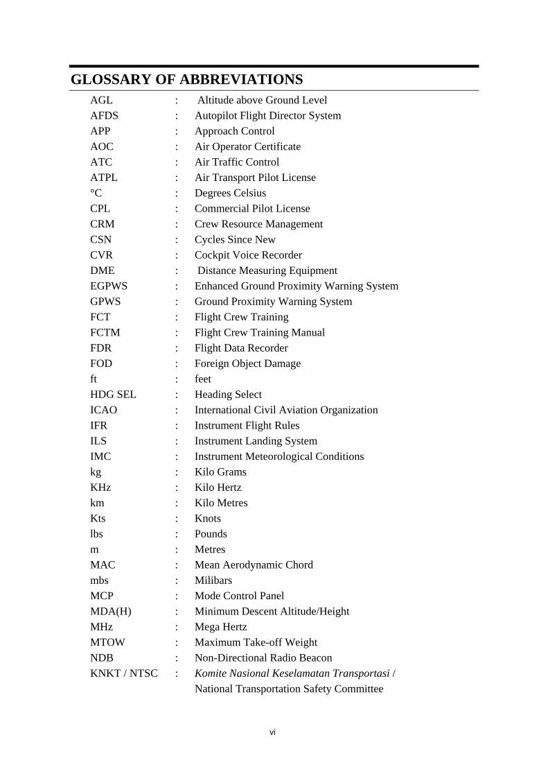
GLOSSARY OF ABBREVIATIONS AGL : Altitude above Ground Level AFDS : Autopilot Flight Director System APP : Approach Control AOC : Air Operator Certificate ATC : Air Traffic Control ATPL : Air Transport Pilot License °C : Degrees Celsius CPL : Commercial Pilot License CRM : Crew Resource Management CSN : Cycles Since New CVR : Cockpit Voice Recorder DME : Distance Measuring Equipment EGPWS : Enhanced Ground Proximity Warning System GPWS : Ground Proximity Warning System FCT : Flight Crew Training FCTM : Flight Crew Training Manual FDR : Flight Data Recorder FOD : Foreign Object Damage ft : feet HDG SEL : Heading Select ICAO : International Civil Aviation Organization IFR : Instrument Flight Rules ILS : Instrument Landing System IMC : Instrument Meteorological Conditions kg : Kilo Grams KHz : Kilo Hertz km : Kilo Metres Kts : Knots lbs : Pounds m : Metres MAC : Mean Aerodynamic Chord mbs : Milibars MCP : Mode Control Panel MDA(H) : Minimum Descent Altitude/Height MHz : Mega Hertz MTOW : Maximum Take-off Weight NDB : Non-Directional Radio Beacon KNKT / NTSC : Komite Nasional Keselamatan Transportasi / National Transportation Safety Committee
vii
PF : Pilot Flying PIC : Pilot in Command PM : Pilot Monitoring QFE : Height above airport elevation (or runway threshold elevation)
based on local station pressure QNH : Altitude above mean sea level based on local station pressure ROD : Rate of Descend sct : Scattered SOP : Standard Operating Procedure TNI AU / IAF : TNI Angkatan Udara / Indonesia Air Force TOW : Take-off Weight TSN : Time Since New Twr : Tower USA : United State of America UTC : Universal Time Coordinate VFR : Visual Flight Rules VMC : Visual Meteorological Conditions VNAV : Vertical Navigation VOR : VHF omnidirectional radio range Vref : Reference Landing Approach Speed
1
INTRODUCTION
SYNOPSIS On 22 July 2011, a Boeing 737-300 aircraft registered PK-GGO was being operated by PT. Garuda Indonesia Airways as a scheduled passenger flight GA 292, from Soekarno - Hatta International Airport (WIII) Jakarta to Abdul Rahman Saleh Airport (WARA) Malang.
The flight crew member was three pilots which consist of Pilot in Command (PIC) acted as Pilot Monitoring (PM), First Officer (FO) who was under a line training acted as Pilot Flying (PF), Second in Command (SIC) a qualified FO acted as a third pilot occupied the pilot jump seat and 5 Flight Attendants (FA). The aircraft departed from Jakarta at 0546 UTC and carried 100 passengers.
During the flight there were no abnormal condition related to aircraft system or other significant information was reported.
The ATC instructed the pilot to commence the VOR approach Runway 35 and circling Runway 17. The pilots were able to see the runway at approximate 4 DME and continued the circling procedure by joined circuit pattern of runway 17. When turned on the base leg runway 17, the PM saw and assessed that the aircraft was above the normal glide path, turned too early and the aircraft was on the right of the centerline. Realizing to the conditions, the PM decided to take over the control and continued the approach to land. The PIC tried to correct the glide path by increasing the rate of descend (ROD), reducing the power and rolled to bring the aircraft aligned with the runway centerline.
At 0709 UTC, the aircraft touched down on runway 17 and was slightly deviated to the right of the runway centerline and stopped on the runway. The ATC instructed the pilot to stop the aircraft and verified of a probability of a hard landing which was confirmed by the pilot. The FDR recorded vertical acceleration of 3.473 G.
There were no one injured in this occurrence.
The investigation had determined that there were no issues with the aircraft and all systems were operating normally. The analysis was focus on these following 3 safety issues:
• Un-stabilized approach below 500ft. • The decision to take over the control and continued the landing.
The investigation concluded that the aircraft approach was un-stabilized since 500 ft prior to land. The decision to take over control during the un-stabilized approach was not consistent to the operator standard operating procedures as well as the Crew Resources Management (CRM) Policy implementation.
At the time of issuing this Final Report, the Komite Nasional Keselamatan Transportasi has been informed of safety actions resulting from this accident by PT. Garuda Indonesia and the Indonesia Air Force Base Abdul Rahman Saleh as the airport operator.
Included in this final report, the KNKT has issued several safety recommendations to the PT. Garuda Indonesia and Directorate General of Civil Aviation to address the safety issues identified in this final report.
2
1. FACTUAL INFORMATION 1.1 History of the Flight
On 22 July 2011, a Boeing 737-300 aircraft registered PK-GGO was being operated by PT.Garuda Indonesia Airways as a scheduled passenger flight from Soekarno - Hatta International Airport (WIII) Jakarta to Abdul Rahman Saleh Airport (WARA) Malang1 with flight numberGA 292.
The flight crew member was three pilots which consisted of Pilot in Command (PIC), one First Officer (FO) under a line training, Second in Command (SIC) a qualified FO and 5 Flight Attendants (FA). This flight carried 100 passengers.
The aircraft departed from Soekarno - Hatta International Airport, Jakarta at 0546 UTC to Malang. In this flight, the FO under line training acted as Pilot Flying (PF) and the PIC acted as Pilot Monitoring (PM) while the SIC acted as a third pilot occupied the jump seat.
During the flight there was no abnormal condition related to aircraft system or other significant information was reported. The flight from the departure until commenced for approach was uneventful.
During descend the Abdul Rahman Saleh Tower controller2 informed the pilot that there were two traffics ahead of them and instructed to fly over the VOR/DME prior to approach runway 35.
After traffic permitted, the pilot instructed to commence the VOR/DME approach runway 35 and circling runway 17. This procedure was due to the latest surface wind condition was southerly with velocity between 10-15kts.The pilots acknowledged the instruction and flew the aircraft according to the procedure as instructed.
During the final VOR/DME approach runway 35, the pilots were able to see the runway at approximate 4 DME and continued the circling procedure to join circuit pattern of runway 17.
Based on pilot interview, the pilot stated that while turning on base leg runway 17, the PIC saw and assessed that the aircraft turned too early which might resulted to the aircraft above normal glide path and on the right of the runway centerline extension. Realizing to the conditions, the PIC decided to take over the control and continued the approach to land.
The PIC corrected the glide path by increasing the rate of descend, reducing the power and rolled to bring the aircraft align with the runway centerline.
At 0708:25 UTC, the aircraft touched down on runway 17 slightly on the right of the runway centerline and decelerated to taxi speed. The pilot then conducted a 180° turn at the turning area to taxi to the apron. While taxi,the ATC controller instructed the pilot to stop the aircraft and asked of a probability of a hard landing occurrence. The pilot confirmed that the aircraft experienced a hard landing.
1 Abdul Rahman Saleh Airport (WARA) Malang will be named as Malang for the purpose of this report.
2 Abdul Rahman Saleh Tower controller will be named as ATC controller for the purpose of this report.
3
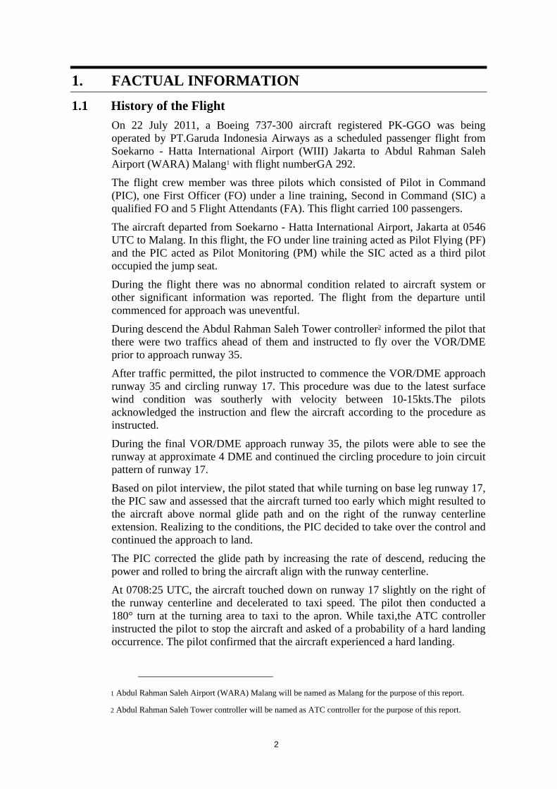
Figure 1:The flight profile from approximately 300 feet AGL based on FDR animation
Following the report of hard landing, the local Airport Safety Officers conducted runway inspection. The inspection found some metal debris on the touchdown area of runway 17 which were parts of the nose wheel of the aircraft.
While waiting for further clearance from ATC controller, the pilots checked the aircraft system and indicators which might exist as consequence of the hard landing but not found any abnormality.
After completion the runway inspection the Airport Safety Officer informed to the ATC controller that the aircraft safe to continue taxi. The pilot taxied the aircraft to the apron and disembarked the passengers.
No one injured in this occurrence.
After the engines shutdown the PIC requested to the maintenance personnel to conduct the hard landing inspection.
During the visual inspection, found that nose wheel hub broken, left engine inlet cowling and several vane blades damaged. Based on the finding of the initial inspection, the aircraft was grounded for further damage assessment and repair.
4
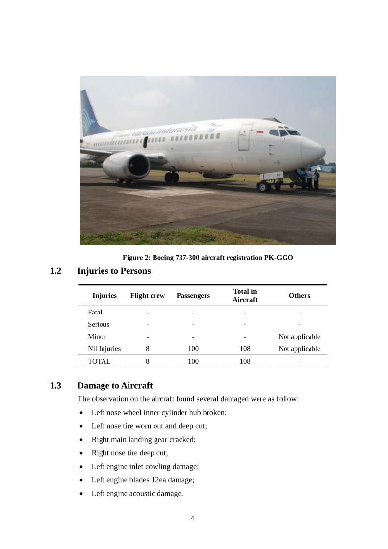
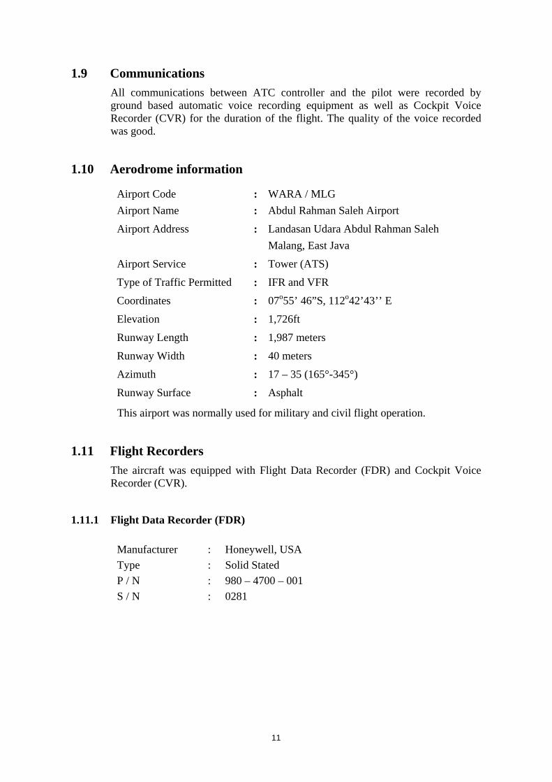
Figure 2: Boeing 737-300 aircraft registration PK-GGO
1.2 Injuries to Persons
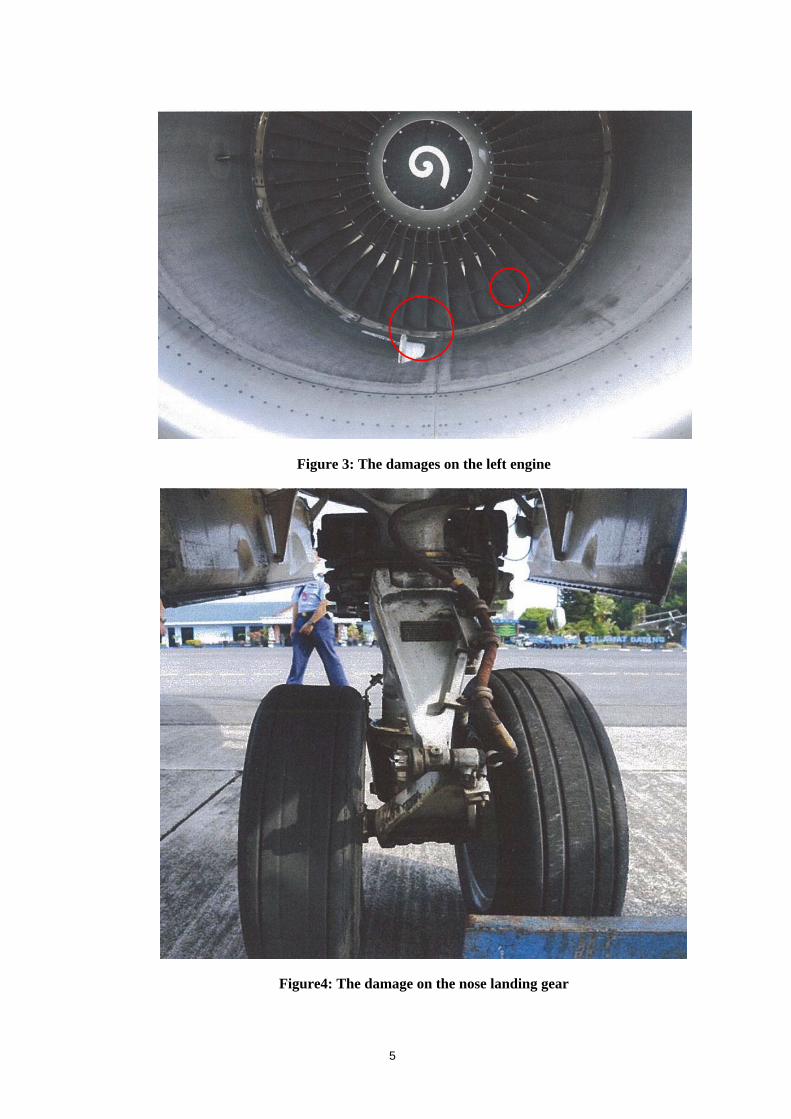
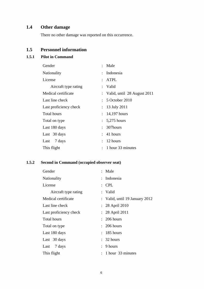
1.3 Damage to Aircraft The observation on the aircraft found several damaged were as follow:
• Left nose wheel inner cylinder hub broken;
• Left nose tire worn out and deep cut;
• Right main landing gear cracked;
• Right nose tire deep cut;
• Left engine inlet cowling damage;
• Left engine blades 12ea damage;
• Left engine acoustic damage.
Injuries Flight crew Passengers Total in Aircraft Others
Fatal - - - -
Serious - - - -
Minor - - - Not applicable
Nil Injuries 8 100 108 Not applicable
TOTAL 8 100 108 -
5
Figure 3: The damages on the left engine
Figure4: The damage on the nose landing gear
6
1.4 Other damage There no other damage was reported on this occurrence.
1.5 Personnel information 1.5.1 Pilot in Command
Gender : Male
Nationality : Indonesia
License : ATPL
Aircraft type rating : Valid
Medical certificate : Valid, until 28 August 2011
Last line check : 5 October 2010
Last proficiency check : 13 July 2011
Total hours : 14,197 hours
Total on type : 5,275 hours
Last 180 days : 307hours
Last 30 days : 41 hours
Last 7 days : 12 hours
This flight : 1 hour 33 minutes
1.5.2 Second in Command (occupied observer seat)
Gender : Male
Nationality : Indonesia
License : CPL
Aircraft type rating : Valid
Medical certificate : Valid, until 19 January 2012
Last line check : 28 April 2010
Last proficiency check : 28 April 2011
Total hours : 206 hours
Total on type : 206 hours
Last 180 days : 185 hours
Last 30 days : 32 hours
Last 7 days : 9 hours
This flight : 1 hour 33 minutes
7
1.5.3 First Officer 2 (as Pilot Flying)
Gender : Male Date of birth : 5 January 1983
Nationality : Indonesia
License : CPL
Aircraft type rating : Valid
Medical certificate : Valid, until 13 December 2011
Last proficiency check : 14 April 2011
Total hours : 457 hours
Total on type : 457 hours
Last 180 days : 243 hours
Last 30 days : 48 hours
Last 7 days : 12 hours
This flight : 1 hour 33 minutes
1.6 Aircraft Information 1.6.1 General
Aircraft manufacturer : Boeing Company, USA
Aircraft model/type : 737 - 300
Serial number : 28736
Year of manufacture : 1998
Aircraft registration : PK-GGO Certificate of Registration : 1837
Valid to : 11 March 2012
Certificate of Airworthiness : 1837
Valid to : 25 June 2012
TSN : 32,625 hours
CSN : 24,998 cycles
MTOW : 63,276kg
Actual Take Off Weight : 52,822 kg
Estimated Landing Weight : 49,472 kg
Last Major Inspection : A66 inspection dated 11 June 2011 at 32,354 FH
8
1.6.2 Engines
Engine type : Turbofan
Manufacturer : CFM International, Canada
Model : CFM56-3C1
Serial Number Engine #1 : 858961
TSN : 30,321 hours
CSN : 23,320 cycles
Serial Number Engine #2 : 858659
TSN : 29,628 hours
CSN : 24,239 cycles
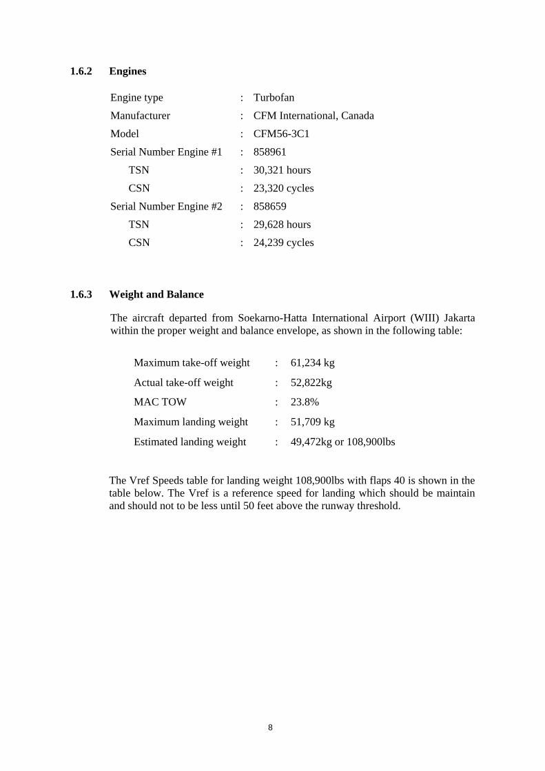
1.6.3 Weight and Balance
The aircraft departed from Soekarno-Hatta International Airport (WIII) Jakarta within the proper weight and balance envelope, as shown in the following table:
Maximum take-off weight : 61,234 kg
Actual take-off weight : 52,822kg
MAC TOW : 23.8%
Maximum landing weight : 51,709 kg
Estimated landing weight : 49,472kg or 108,900lbs
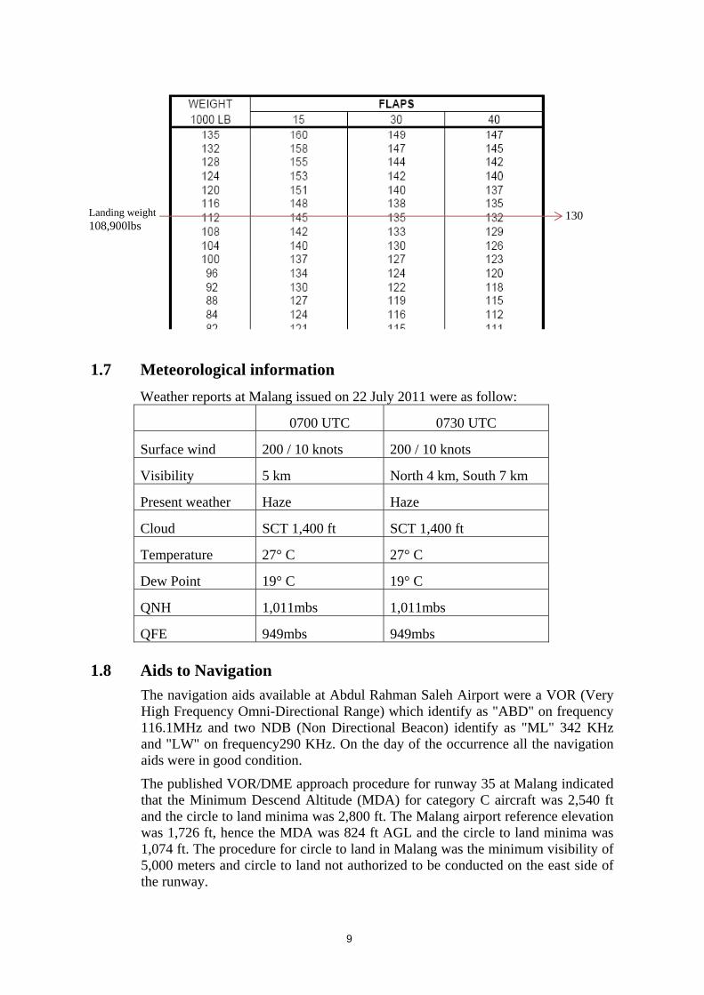
The Vref Speeds table for landing weight 108,900lbs with flaps 40 is shown in the table below. The Vref is a reference speed for landing which should be maintain and should not to be less until 50 feet above the runway threshold.
9
1.7 Meteorological information Weather reports at Malang issued on 22 July 2011 were as follow:
0700 UTC 0730 UTC
Surface wind 200 / 10 knots 200 / 10 knots
Visibility 5 km North 4 km, South 7 km
Present weather Haze Haze
Cloud SCT 1,400 ft SCT 1,400 ft
Temperature 27° C 27° C
Dew Point 19° C 19° C
QNH 1,011mbs 1,011mbs
QFE 949mbs 949mbs
1.8 Aids to Navigation The navigation aids available at Abdul Rahman Saleh Airport were a VOR (Very High Frequency Omni-Directional Range) which identify as "ABD" on frequency 116.1MHz and two NDB (Non Directional Beacon) identify as "ML" 342 KHz and "LW" on frequency290 KHz. On the day of the occurrence all the navigation aids were in good condition.
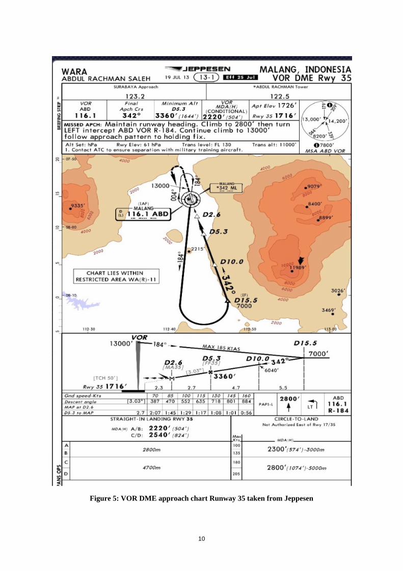
The published VOR/DME approach procedure for runway 35 at Malang indicated that the Minimum Descend Altitude (MDA) for category C aircraft was 2,540 ft and the circle to land minima was 2,800 ft. The Malang airport reference elevation was 1,726 ft, hence the MDA was 824 ft AGL and the circle to land minima was 1,074 ft. The procedure for circle to land in Malang was the minimum visibility of 5,000 meters and circle to land not authorized to be conducted on the east side of the runway.
Landing weight 108,900lbs
130
10
Figure 5: VOR DME approach chart Runway 35 taken from Jeppesen
11
1.9 Communications All communications between ATC controller and the pilot were recorded by ground based automatic voice recording equipment as well as Cockpit Voice Recorder (CVR) for the duration of the flight. The quality of the voice recorded was good.
1.10 Aerodrome information
Airport Code : WARA / MLG Airport Name : Abdul Rahman Saleh Airport
Airport Address : Landasan Udara Abdul Rahman Saleh Malang, East Java
Airport Service : Tower (ATS)
Type of Traffic Permitted : IFR and VFR
Coordinates : 07o55’ 46”S, 112o42’43’’ E
Elevation : 1,726ft
Runway Length : 1,987 meters
Runway Width : 40 meters
Azimuth : 17 – 35 (165°-345°)
Runway Surface : Asphalt
This airport was normally used for military and civil flight operation.
1.11 Flight Recorders The aircraft was equipped with Flight Data Recorder (FDR) and Cockpit Voice Recorder (CVR).
1.11.1 Flight Data Recorder (FDR)
Manufacturer : Honeywell, USA Type : Solid Stated P / N : 980 – 4700 – 001 S / N : 0281
12
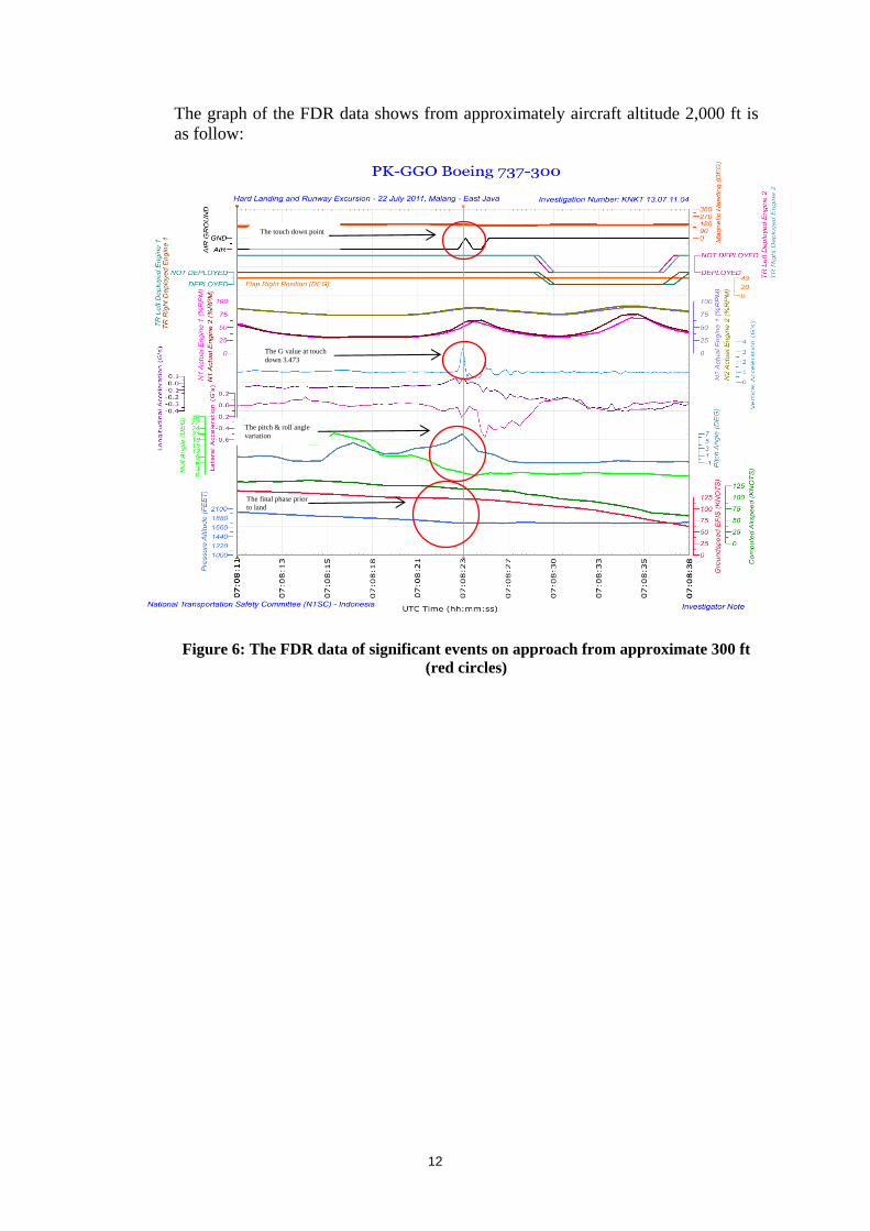
The graph of the FDR data shows from approximately aircraft altitude 2,000 ft is as follow:
Figure 6: The FDR data of significant events on approach from approximate 300 ft (red circles)
The G value at touch down 3.473
The pitch & roll angle variation
The final phase prior to land
The touch down point
13
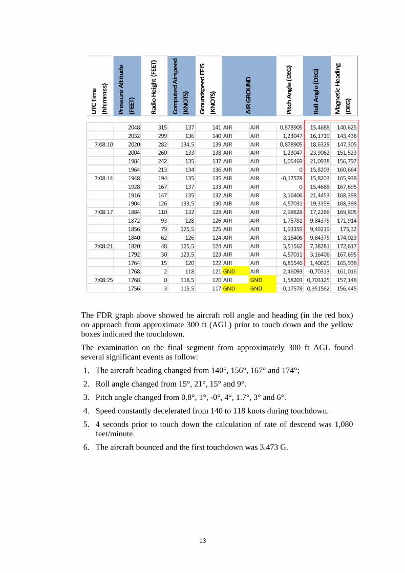
The FDR graph above showed he aircraft roll angle and heading (in the red box) on approach from approximate 300 ft (AGL) prior to touch down and the yellow boxes indicated the touchdown.
The examination on the final segment from approximately 300 ft AGL found several significant events as follow:
1. The aircraft heading changed from 140°, 156°, 167° and 174°;
2. Roll angle changed from 15°, 21°, 15° and 9°.
3. Pitch angle changed from 0.8°, 1°, -0°, 4°, 1.7°, 3° and 6°.
4. Speed constantly decelerated from 140 to 118 knots during touchdown.
5. 4 seconds prior to touch down the calculation of rate of descend was 1,080 feet/minute.
6. The aircraft bounced and the first touchdown was 3.473 G.
14
1.11.2 Cockpit Voice Recorder (CVR)
Manufacturer : Honeywell, USA Type : Solid Stated P / N : 980 – 6020 – 001 S / N : 1194
The CVR removed from the aircraft by the Garuda Maintenance Facility personnel and sent to the KNKT laboratory for investigation purposes. The CVR contained four channels of 30 minutes and two channels of 120 minutes of good quality recording including all the conversations between pilots and air traffic controller involved in this serious incident flight.
The significant excerpts taken from CVR after PIC realizedthat the aircraft was too high while turning on base leg then took over control and acted as PF are as follows:
At 07:06:49 UTC FO requested to select gear down
At 07:07:17 PIC reminded the FO for the selection of flap 40
At 07:07:23 Sound of similar the auto pilot disengaged
At 07:07:24 PIC reported that the landing checklist completed
At 07:07:36 PIC reminded the FO to set the runway heading and was acknowledged by the FO.
At 07:07:41 FO set runway heading.
At 07:07:44 EGPWS sounded ‘FIVE HUNDRED’.
At 07:07:45 PIC asked to the FO about the runway position
At 07:07:48 PIC saw the runway and expressing a surprise
At 07:07:48 PIC reminded that the speed was not on the target
At 07:07:54 PIC expressing that the last turn was too early.
At 07:07:59 PIC asked that they have received clearance to land and was replied that the clearance has received.
At 07:08:20 FO called to PIC to check the aircraft speed.
At 07:08:21 GPWS “FIFTY” (reminder that the aircraft altitude at 50 ftAGL).
At 07:08:22 GPWS “FOURTY”
At 07:08:23 GPWS “THIRTY”
At 07:08:24 GPWS “TWENTY”
At 07:08:24 GPWS “TEN”
At 07:08:25 the first aircraft touched down

15
1.12 Wreckage and Impact Information The tire marks of both main wheels and nose wheel were found on the runway surface. The marks started from touchdown at about 300 meters from the beginning of runway 17 heading to the right until the mark of the right main tire out of pavement at about 100 meters from the initial marks.
Figure7:The tire marks found on the runway
Some broken parts of nose wheel hub were found on the runway by Airport Safety Officer as shown on figure below.
Figure 8: The broken parts of nose wheel hub
16
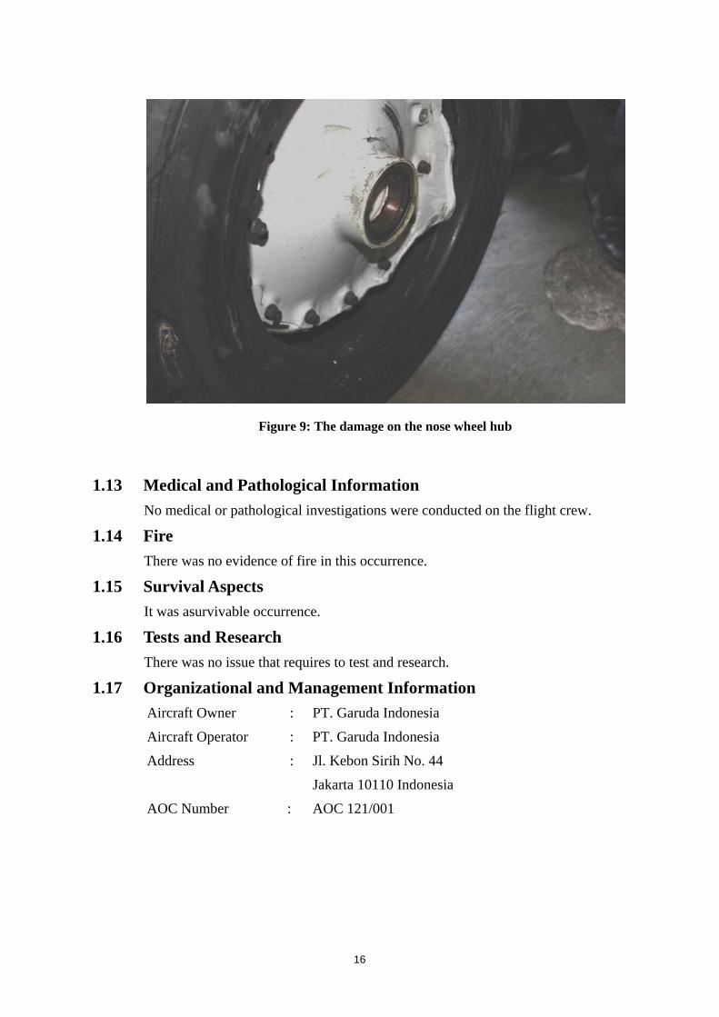
Figure 9: The damage on the nose wheel hub
1.13 Medical and Pathological Information
No medical or pathological investigations were conducted on the flight crew.
1.14 Fire There was no evidence of fire in this occurrence.
1.15 Survival Aspects It was asurvivable occurrence.
1.16 Tests and Research There was no issue that requires to test and research.
1.17 Organizational and Management Information Aircraft Owner : PT. Garuda Indonesia
Aircraft Operator : PT. Garuda Indonesia
Address : Jl. Kebon Sirih No. 44
Jakarta 10110 Indonesia
AOC Number : AOC 121/001
17
1.17.1 Operator Standard Operating Procedures
FCTM (Flight Crew Training Manual) FCT 737 CL (TM), 4.37
Circling Approach - General
The circling approach should be flown with landing gear down, flaps 15, and atflaps 15 maneuvering speed. Use the weather minima associated with the anticipated circling speed. Maintain MCP altitude or MDA(H) using ALT HOLD mode or VNAV ALT mode (as installed) and use HDG SEL for the maneuvering portion of the circling approach. If circling from an ILS approach, fly the ILS inVOR/LOC and VNAV or V/S modes.
Note : If the MDA(H) does not end in “00”, set the MCP altitude to the nearest 100 feet above the MDA(H) and circle at MCP altitude. Use of the APP mode for descent to a circling approach is not recommended forseveral reasons:
• exiting the APP mode requires initiating a go-around or disconnecting the autopilot and turning off the flight directors.
• The AFDS (Autopilot Flight Director System) does not level off at MCP altitude
When in altitude hold at MDA(H) and prior to commencing the circling maneuver, set the missed approach altitude.
Initiating the turn to base leg, select landing flaps and begin decelerating to the approach speed plus wind correction. To avoid overshooting final approach course, adjust the turn to final to initially aim at the inside edge of the runway threshold. Timely speed reduction also reduces turning radius to the runway. Complete the landing checklist. Do not descend below MDA(H) until intercepting the visual profile to the landing runway.
Leaving MDA(H), disengage the autopilot and auto throttle. After intercepting the visual profile, cycle both F/D to OFF, then to ON. This eliminates unwanted commands for both pilots and allows F/D guidance in the event of a go-around. Complete the landing.
Note : If a go-around is selected with F/D switches off, the F/D commands disappear when the first pitch or roll mode is selected or engaged.
Holding, Approach and Landing .FCT 737 CL (TM) 4.5 - 4.6
Stabilized Approach Requirements
Maintaining a stable speed, descent rate, and vertical/lateral flight path in landing configuration is commonly referred to as the stabilized approach concept.
Any significant deviation from planned flight path, airspeed, or descent rate should be announced. The decision to execute a go-around is no indication of poorperformance.
Note: Do not attempt to land from an unstable approach.
Recommended Elements of a Stabilized Approach
The following recommendations are consistent with criteria developed by the Flight Safety Foundation.
18
All approaches should be stabilized by 1,000 feet above airport elevation in instrument meteorological conditions (IMC) and by 500 feet above airport elevation in visual meteorological conditions (VMC). An approach is considered stabilized when all of the following criteria are met: • the aircraft is on the correct flight path • only small changes in heading/pitch are required to maintain the correct
flight path • the aircraft speed is not more than VREF + 20 knots indicated airspeed and
not less than VREF • the aircraft is in the correct landing configuration • sink rate is no greater than 1,000 fpm; if an approach requires a sink rate
greater than 1,000 fpm, a special briefing should be conducted • power setting is appropriate for the aircraft configuration • all briefings and checklists have been conducted.
Specific types of approaches are stabilized if they also fulfill the following: • ILS approaches should be flown within one dot of the glide slope and localizer • a category II or category III ILS approach should be flown within the
expanded localizer band • during a circling approach, wings should be level on final when the aircraft
reaches 300 feet above airport elevation.
Unique approach procedures or abnormal conditions requiring a deviation from the above elements of a stabilized approach require a special briefing.
Note: An approach that becomes unstabilized below 1,000 feet above airport elevation in IMC or below 500 feet above airport elevation in VMC requires an immediate go-around.
Approach charts use the abbreviation DA(H) or MDA(H). A decision altitude “DA” or minimum descent altitude “MDA” is referenced to MSL and the parenthetical height “(H)” is referenced to TDZE or threshold elevation. Example: A DA(H) of 1,440’ (200’) is a DA of 1,440’ with a corresponding height aboveTDZ of 200’.
When RVR is reported for the landing runway, it typically is used in lieu of the reported meteorological visibility.
1.17.2 Training and Assessment
1.5 TRAINING AND ASSESSMENT
1.5.2 Assessments Standards
05. GENERAL TOLERANCES • Height : ± 200 feet Maximum ±100 feet NOT more than 15 seconds • DH : 0 / + 50 feet to initiate overshoot • MDA : 0 / + 50 feet to maintain • Airspeed : ± 15 kts Maximum ± 10 kts in cruise NOT more than 15 seconds
19
± 5 kts on approach • Heading : ± 10º degrees of assigned or intended heading • Airway Tracking : 5° of specified track ILS approach : ½ scale deflection of “G/S or LOC” (1 scale =1 dot=1
degree for ILS) • VOR approach : ½ scale deflection (1 scale = 1 dot = 5 degrees for
VOR)
1.17.3 Crew Resource Management
1.4.2 CREW RESOURCE MANAGEMENT (CRM)
The Principles, Philosophy, Policies, Procedures and Practices (Behaviours) define the Garuda Indonesia approach to CRM. Principles form the basis for our philosophy; our philosophy shapes our policies; policies guide the development of procedures and practices.
1.4.2.2 CRM Philosophy (a). CRM is the effective use of all available resources -- people, equipment,
and information -- to achieve the highest possible levels of safety and efficiency.
(b). CRM ability and a facility for teamwork shall be selection criteria for all crewmembers.
(c). CRM is based on the principle of synergy (teamwork) functioning within a cultural environment that supports and encourages human growth and commitment.
(d). CRM involves the continuous improvement of procedures, attitudes, and behaviours, applying human factor concepts to enhance individual and crew performance.
(e). CRM training is focused on specific teamwork, communication, decision-making, and workload management behaviours that have been proven to enhance personal effectiveness and job satisfaction. As a result of CRM training, employees will be better able to function as members of self-criticizing, self-correcting teams.
1.4.2.3 CRM Policy (a). CRM principles and behaviours must be fully integrated into all aspects
of flight operations training. (b). Periodic CRM assessments and performance feedback will be conducted
for all flight crewmembers, flight-attendants, and dispatchers, in order to assure effective teamwork.
(c). Flight schedules for crewmembers will be prepared and administered to assure adequate rest and safe crewpairings (i.e., new captains will not be scheduled with new first officers unless a DGCP/CCP or FIA is part of the crew).
(d). The PIC shall be responsible for establishing an environment of trust and mutual-commitment prior to eachflight, encouraging his fellow crewmembers to speak up and to accept mutual responsibility for the safety and well-being of the passengers, cargo, and equipment entrusted to them. “What’s right, not who’s right” shall be the motto of all
20
members of the Garuda Indonesia operating team. (e). Each Garuda Indonesia crewmember shall be responsible for notifying
the pilot-in command of any condition or circumstance that might endanger the aircraft or impair the performance of any flight crewmember.
(f). CRM skills and performance will be periodically evaluated at all organizational levels to provide regular feedback and ensure continuous improvement.
(g). CRM skills and performance will be a factor in the promotion of all Garuda Indonesia crewmembers.
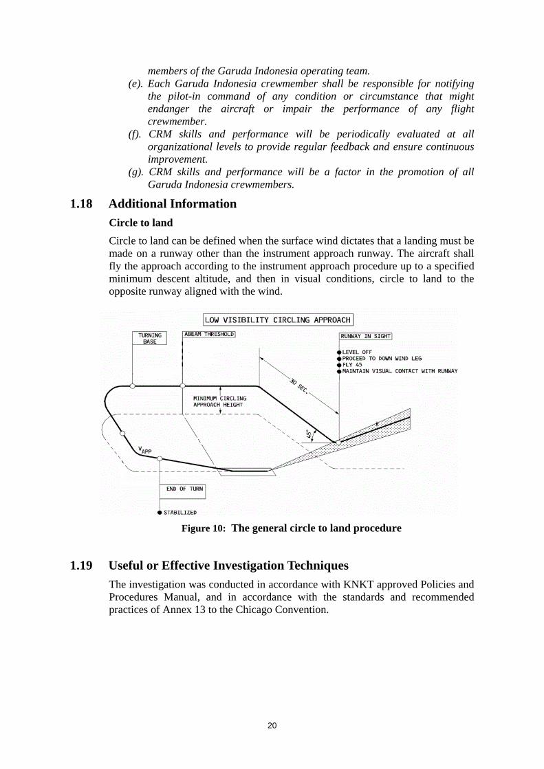
1.18 Additional Information Circle to land Circle to land can be defined when the surface wind dictates that a landing must be made on a runway other than the instrument approach runway. The aircraft shall fly the approach according to the instrument approach procedure up to a specified minimum descent altitude, and then in visual conditions, circle to land to the opposite runway aligned with the wind.
Figure 10: The general circle to land procedure
1.19 Useful or Effective Investigation Techniques The investigation was conducted in accordance with KNKT approved Policies and Procedures Manual, and in accordance with the standards and recommended practices of Annex 13 to the Chicago Convention.

21
2. ANALYSIS The investigation of hard landing involving a B737-300 aircraft, PK-GGO on 22 July 2011 at Abdul Rahman Saleh Airport, Malang determined that there was no issue related to the aircraft.
Therefore the analysis will focus on the following safety issues:
• Approach below 500ft; • The decision to take over the control and continued the landing.
2.1 Approach below 500ft The flight conducted VOR/DME approach runway 35 and continued for circle to land runway 17.The VOR/DME approach procedure chart of runway 35 at Malang showed that the inbound track was 342° and the circle to land altitude was 2,800ft or 1,074 ft above the airport altitude reference.
The FDR recorded that during the final segment from approximately 300ft AGL, found several significant events as follow:
1. The aircraft heading changed from 140°, 156°, 167° and 174°; 2. Roll angle changed from 15°, 21°, 15° and 9°. 3. Pitch angle changed from 0.8°, 1°, -0°, 4°, 1.7°, 3° and 6°. 4. Speed constantly decelerated from 137 to 118 knots until touchdown.
5. 4 seconds prior to touch down the calculation of rate of descend was 1,080 feet/minute.
6. The aircraft bounced and the first touchdown the recorded vertical acceleration was 3.473 G.
The FCTM also added the Recommended Elements of a Stabilized Approach which should be accomplished by 1,000 ft above airport elevation in instrument meteorological conditions (IMC) and by 500 ft above airport elevation in visual meteorological conditions (VMC). The procedure also noted that an approach that becomes un-stabilized below 1,000 ft above airport elevation in IMC or below 500 ft above airport elevation in VMC requires an immediate go-around.A circle to land approach should be performed in VMC hencethe approach should be stabilized at 500 ft.
During the final segment from approximately 300ft AGL, the FDR recorded that aircraft heading were changed from 140° to 174°, and theroll angle varied from 9° to 21°.The changing of heading of more than 30 degrees with roll angle varied between 9° to 21° were not the small roll angle as mentioned in the stabilized approach criteria.
The FDR also recorded that pitch angle changed from 0.8°, 1°, -0°, 4°, 1.7°, 3° to 6 while the aircraft vertical speed reached up to 1,080 ft/minute. The criteria of stabilized approach required sink rate not greater than 1,000 ft/minute.
The aircraft speed recorded decelerated from 140 to 118 kts when the Vref speed for the particular weight was 130 kts. The CVR recorded that on short final the FO called to the PIC to check the speed. The stabilized approach criteria also stated that the aircraft speed should not below Vref.
22
Refer to the recorded data in the FDR indicated that the aircraft was on un-stabilized approach while in an VMC condition until below 300 feet which required to go-around.
2.2 The decision to take over the control and continued the landing The CVR record and the pilot information during the interview it was known that during turning from base leg to final course runway 17, the PIC assessed that the aircraft was turned too early, higher than normal glide and on the right of the centerline.
Realized the condition and considered that the PF was under line training the PIC decided to take over the control and continued the approach to land. The PIC considered that the aircraft was on condition that might not be able to be handled by the SIC and decided to take over the control and continued the approach to land.
The PIC tried to correct glide path by increase rate of descend and reduced the thrust levers simultaneously the PIC rolled to align with runway centerline. The PIC continued the approach and landing while the approach was un-stabilized.
The Boeing FCTM on subtitle Holding, Approach and Landing (FCT 737 CL (TM) 4.5 - 4.6) Stabilized Approach Requirements, stated:
Any significant deviation from planned flight path, airspeed, or descent rate should be announced. The decision to execute a go-around is no indication of poor performance.
Note: Do not attempt to land from an unstable approach.
According to the operator CRM Policy which stated, “each Garuda Indonesia crewmember shall be responsible for notifying the pilot-in command of any condition or circumstance that might endanger the aircraft or impair the performance of any flight crewmember”.
The analysis chapter 2.1 of this report described that the aircraft was in condition of un-stabilized approach below 300 feet AGL on final approach. The CVR did not record any statement or comment of both FOs on board to remind the PIC of un-stabilized condition which was required by operator CRM policy.
The descriptions above showed that the PIC decision to take over control and continued the approach on an un-stabilized approach and absent of reminder from the other crew was not consistent with the operator standard operating procedures as well as the CRM Policy.
23
3. CONCLUSION 3.1 Findings
1. The aircraft was airworthy and there was no system malfunction reported prior to the serious incident.
2. All three pilots have valid license and medical certificates.
3. The aircraft was within the correct weight and balance limitation.
4. The flight conducted VOR/DME approach runway 35 and circle to land to runway 17 procedures due to the wind condition.
5. The pilot was able to see the runway at about 4 DME then continued following the circling procedure in VMC.
6. While turning on the base leg runway 17, was turned too early, higher than normal glide and on the right of the centerline which might not be able to be handled by the SIC and took over the control
7. The PIC tried to correct glide path by increase rate of descend and reduced the thrust levers simultaneously the PIC rolled to align with runway centerline.
8. The FDR data recordedthat aircraft heading were changed from 140° to 174°, and the roll angle varied from 9° to 21° which were indication that the aircraft was on un-stabilized approach.
9. There was no call out from any other crew member to remind the un-stabilized condition.
10. The aircraft touched down with vertical acceleration of 3.473 G then bounced.The aircraft veered off to the right of runway centerline.
11. The runway inspection found some broken parts of nose wheel hub.
3.2 Contributing Factor During thecircle to land approach, the aircraft was turned too early that might cause the aircraft higher above the normal approach path and not on the correct track and was taken over by the PIC.
The approach was un-stabilized until below 300 feet and the absent of reminder from the other crew to go-around. These actions inconsistent to the operator standard operating procedures as well as the CRM philosophy.
24
4. SAFETY ACTIONS At the time of issuing this Final Report, the Komite Nasional Keselamatan Transportasi has been informed of several safety actions taken PT. Garuda Indonesia as resultof this accident. The detail is as follows:
a. PT. Garuda Indonesia has issued an Engineering Instruction Sheet No. B3/05-0202-TEA on 23 July 2011 about “Maintenance after Hard landing and Off-Runway Excursion”. This Engineering Instruction issued as an instructions to conduct inspection of the PK-GGO aircraft and do corrective action as necessary,
b. PT. Garuda Indonesia conducted a bore scope inspection for CFM56-3 engine serial number 858961 and serial number 858659,
c. PT. Garuda Indonesia conducted a series of NDT inspections with High FrequencyEddy Current andultra-sonic methods.
25
5. RECOMMENDATION Based on the examination of the factual data and the safety issue findings which contributed to this serious incident such as, the OperatorStandard Operating Procedures mentioned that when the approach becomes un-stabilized at and below 500ft above airport elevation in VMC, it requires an immediate go-around.
KNKT has received Engineering Instruction related to the inspection and corrective action for the aircraft.
Therefore the Komite Nasional Keselamatan Transportasi issued several safety recommendations addressed to:
5.1 Recommendation to PT. Garuda Indonesia a It was identified that in consistency to the operator policy and procedure
related to the un-stabilized approach and landing procedures was as a contributing factor in this serious incident. KNKT recommends to re-emphasize the implementation of the published standard operating procedures and toconsider that this condition might possible extend to the other flight crew.
b Associated with the PIC decision, that the implementation of the CRM Philosophy was requiring flight crew focuseson specific teamwork, communication, decision-making, and workload management behaviors that have been proven to enhance personal effectiveness and job satisfaction. As such, KNKT recommends to re-emphasizea well implementation of the CRM philosophy especiallyto the topics described above and to consider that this condition might possible extend to the other flight crew.
5.2 Recommendation to Director General of Civil Aviation The Komite Nasional Keselamatan Transportasi recommends to the Director General of Civil Aviation to monitor and over sighting periodically the recommendation implementation as stated above.