Nanophotonic and Metasurface-based optical devices€¦ · Mikhail Kats . Francesco Aieta . Outline...
49
Photonic Interfaces (or “Metasurfaces”) A modern approach to control the light Patrice Genevet School of Engineering and Applied Sciences Harvard University
Nanophotonic and Metasurface-based optical devices€¦ · Mikhail Kats . Francesco Aieta . Outline of the presentation • Introduction • The concept of optical phase discontinuities
Fermat’s principle, which is commonly know as the principle of least optical path, can predict the propagation of light. It basically says that light travels along a route that minimize this path integral, which is the integral of the refractive index n times the distance. For example in this case, both A and B are in the free space and the shorted route is a straight line
“principle of stationary phase”
( )B
oAk n r dr∫
stationary 2
oo
k πλ
=
A B
Interface (like a mirror)
θ θ
A
B
( )B
An r dr∫ minimum
“principle of least optical path”
Light does not always travel in straight lines
Presenter
Presentation Notes
What you may not know is that there is a more general Fermat’s Principle, called principle of stationary phase. It says that for the actual optical path, this quantity has to be stationary with respect to small variation of the path. In other words the quantity should be a local minimum or maximum.
A B
interface θ θ
( )B
oAk n r dr∫
stationary 2
oo
k πλ
=
Law of Reflection
θi =θr “principle of stationary phase”
θ1
θ2
( )B
oAk n r dr∫
stationary
Law of Refraction or Snell Law
A
B
interface
θ1
θ2
Conventional Optics
Diffractive Optics
Classical optical components
Recent developments in field of optics
Metamaterials and Transformation Optics
A.J. Ward and J.B. Pendry, J. Mod. Opt. 43 (1996) J.B. Pendry, D. Schurig and D.R. Smith, Science 312, 1780 (2006)
Optical cloaking
Propagation of light is controlled by considering artificial 3D materials with designed permittivity and permeability.
What can we do in 2D ? “metasurfaces”
Negative refraction
Introduction to light propagation with phase discontinuities
A sin(ωt - kx x)
x
A sin(ωt - kx x+ Φjump) Φjump
Introduction to light propagation with phase discontinuities
A sin(ωt - kx x)
x1
x
A sin(ωt - kx x+ Φjump) Φjump
Secondary wavelets
Primary wavefront
Envelope
Interface
z
0
Secondary wavelets
Primary wavefront
Envelope
Interface
z
0
Huygens’ principle
Generalized reflection and refraction of light
Suppose interface with a linear gradient of phase delay
dΦ/dx
Presenter
Presentation Notes
In the presence of phase jumps, the law of refraction known as Snell’s law has to be rewritten. Let us assume that the two paths, red and blue, from point A to B are both infinitesimally close to the actual optical path so they have the same total phase shift, including the propagation effect and the phase jumps, which are phi and phi+delta phi for the blue and red paths, respectively. Now let’s look at the phase difference between the two paths. The red light travels an extra distance shown by the solid red line. So here is the propagation phase accumulated during this extra distance. Plus the phase jump at the interface. Together they should equal to those of the blue path. Then you simply rearrange the terms and obtain this elegant equation. The left hand side, if equals to zero, is the ordinary Snell’s law. The right hand side is proportional to the phase gradient along the interface dphi over dx. Similarly we can derive the generalized law of reflection. The two generalized laws tells us that the reflected and the refracted light can essentially point to any arbitrary direction depending on magnitude and the direction phase gradient.
Imposing the stationary phase conditions: konidxSin(θi) +(Φ+dΦ) = kontdxSin(θt)+Φ
Generalized reflection and refraction of light
Suppose interface with a linear gradient of phase delay
dΦ/dx
Presenter
Presentation Notes
In the presence of phase jumps, the law of refraction known as Snell’s law has to be rewritten. Let us assume that the two paths, red and blue, from point A to B are both infinitesimally close to the actual optical path so they have the same total phase shift, including the propagation effect and the phase jumps, which are phi and phi+delta phi for the blue and red paths, respectively. Now let’s look at the phase difference between the two paths. The red light travels an extra distance shown by the solid red line. So here is the propagation phase accumulated during this extra distance. Plus the phase jump at the interface. Together they should equal to those of the blue path. Then you simply rearrange the terms and obtain this elegant equation. The left hand side, if equals to zero, is the ordinary Snell’s law. The right hand side is proportional to the phase gradient along the interface dphi over dx. Similarly we can derive the generalized law of reflection. The two generalized laws tells us that the reflected and the refracted light can essentially point to any arbitrary direction depending on magnitude and the direction phase gradient.
Generalized reflection and refraction of light
Suppose interface with a linear gradient of phase delay
dΦ/dx
Similarly for reflection:
Generalized Snell’s law
Imposing the stationary phase conditions: konidxSin(θi) +(Φ+dΦ) = kontdxSin(θt)+Φ
Presenter
Presentation Notes
In the presence of phase jumps, the law of refraction known as Snell’s law has to be rewritten. Let us assume that the two paths, red and blue, from point A to B are both infinitesimally close to the actual optical path so they have the same total phase shift, including the propagation effect and the phase jumps, which are phi and phi+delta phi for the blue and red paths, respectively. Now let’s look at the phase difference between the two paths. The red light travels an extra distance shown by the solid red line. So here is the propagation phase accumulated during this extra distance. Plus the phase jump at the interface. Together they should equal to those of the blue path. Then you simply rearrange the terms and obtain this elegant equation. The left hand side, if equals to zero, is the ordinary Snell’s law. The right hand side is proportional to the phase gradient along the interface dphi over dx. Similarly we can derive the generalized law of reflection. The two generalized laws tells us that the reflected and the refracted light can essentially point to any arbitrary direction depending on magnitude and the direction phase gradient.
We need optical elements which have:
- Deep subwavelength thickness
- Subwavelength separation
- 2π phase coverage
- High and uniform scattering amplitude
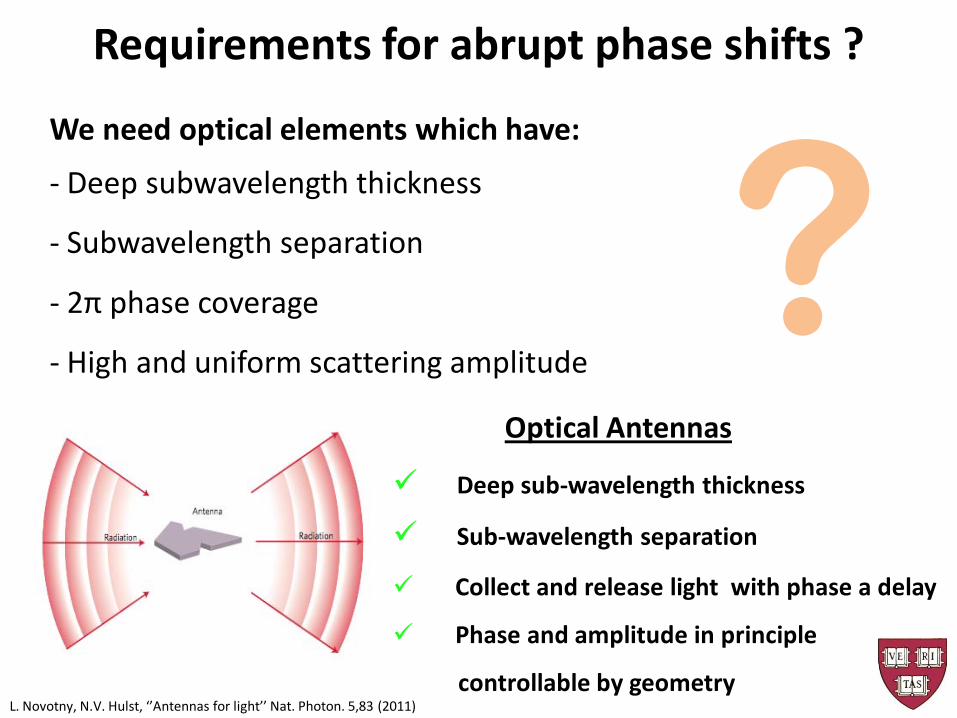
? Requirements for abrupt phase shifts ?
We need optical elements which have:
- Deep subwavelength thickness
- Subwavelength separation
- 2π phase coverage
- High and uniform scattering amplitude
Requirements for abrupt phase shifts ?
Deep sub-wavelength thickness
Sub-wavelength separation
Collect and release light with phase a delay
Phase and amplitude in principle
controllable by geometry
Optical Antennas
? L. Novotny, N.V. Hulst, ‘’Antennas for light’’ Nat. Photon. 5,83 (2011)
ω
The case of a single rod plasmonic antenna
How to create the phase discontinuities ?
Amplitude modulation Maximum phase delay: π
++ --
L1 + + --
L2
ω
How to create the phase discontinuities ?
The case of 2 plasmonic antennas of different length
Einc
Es Ea
Symmetric mode Antisymmetric mode
Einc
Ea Es
Einc
Es Ea
Einc
â ŝ
h ~ λ/2 Antenna resonance condition
h
2h ~ λ/2
Dual-mode operation of a V-antenna solves the amplitude PB
∆ h
Presenter
Presentation Notes
The reason of using V-antennas is that they support two resonance modes, each resonance is associated with a phase shift of pi, bringing the total phase shift to 2pi, which is necessary for a complete control of the wavefront. The other antenna mode, the antisymmetric one, is excited when the incident electric field is perpendicular to the symmetry axis of the antenna. In this case, the field drives current that flows back and forth between the two arms and the current is strongest at the antenna joint.
Einc
Es Ea
Symmetric mode Antisymmetric mode
Einc
Ea
Es
Einc
Es Ea
Einc
∆
â ŝ
h ~ λ/2 Antenna resonance condition
2h ~ λ/2
h
Einc Einc
h
h
2h
Dual-mode operation of a V-antenna solves the amplitude PB
Einc
Es
Eout
Presenter
Presentation Notes
In the symmetric mode, the two arms of the antenna operate almost independently. Therefore the antenna resonance occurs when the arm length h equals to half wavelength. In the antisymmetric mode, the current flows back and force between the two arms and the physical length of the mode is 2h. Therefore, the antenna resonance occurs at 2h equals lambda over 2.
Validation of the full design via simulations The antenna reemissions form a tilted wavefront, and from one side to the other the propagation distance differs by a wavelength
Uniform scattering amplitude Controlled phase responses between 0 to 2π
Presenter
Presentation Notes
We use full-wave simulations to confirm that the phase and amplitude responses of the antennas are as designed. Here the 8 antennas are excited by a plane wave normally incident on the interface from the substrate side. The antenna reemissions form a tilted wavefront, and from one side to the other the propagation distance differs by one wavelength, meaning that the phase difference between the two sides is 2pi. Furthermore, the scattering amplitude looks quite uniform.
2 µm
λ = 8 µm
Sub-wavelength spacing in both x and y dimensions:
metasurfaces
Presenter
Presentation Notes
Experimentally, we use such a structure to create a linear phase gradient along the horizontal direction. Shown in yellow is the unit cell, which is repeated in both the vertical and the horizontal directions. It comprises 8 gold V-shaped antennas on silicon which are carefully designed so that for vertically incident polarization, the phase of the horizontally polarized scattered light increases from 0 to 2pi in step of pi/4 from the left to the right hand side. The structure is designed to work in the mid-ir. I should point out that the distance between antennas are sub-wavelength, so the whole structure is a 2D metamaterial or a metainterface.
ordinary refraction
Incident light
anomalous refraction
θt = arcSin(- λo/Γ)
θt
Γ
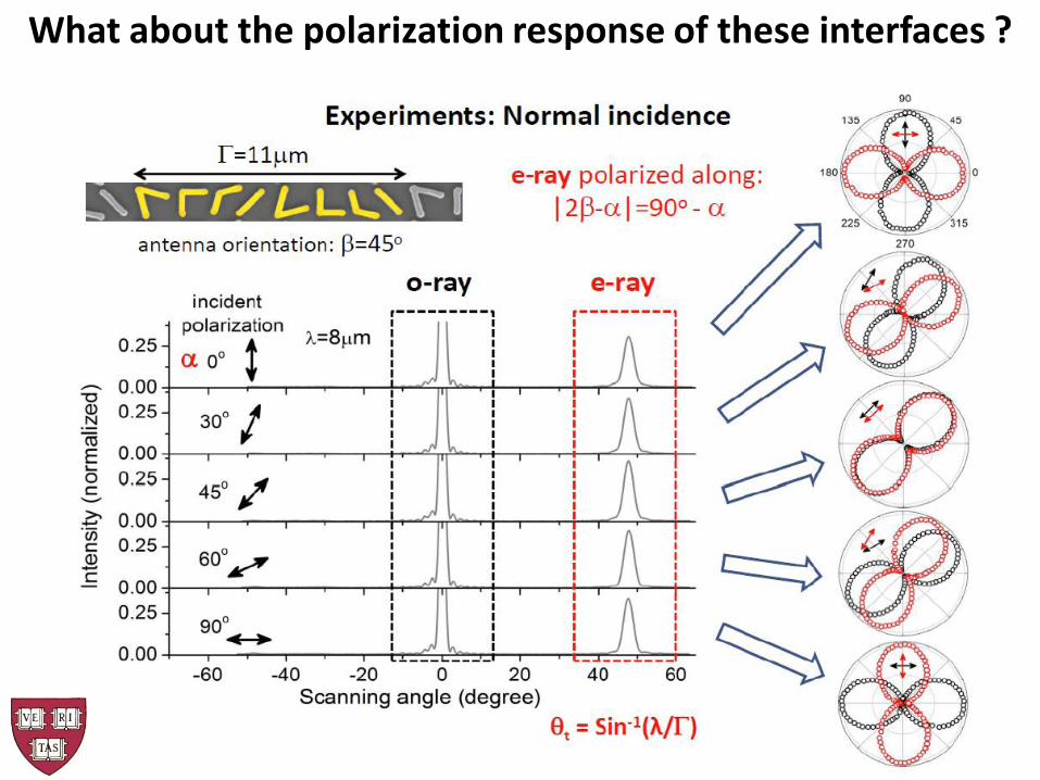
Experiment: Normal incidence
Presenter
Presentation Notes
The simplest situation is normal incidence, where the direct transmission is in the surface normal direction, at zero degree. The anomalous refraction should be away from the surface normal at sita_t. The arrows are calculations according to the generalized Snell’s law, which agrees with experiments very well. The red and black curves are both experimental data and their difference is that that for the red curves we used a polarizer to select the anomalous beams which are inplane polarized, whereas the black curves were taken without the polarizer. The efficiency of generating the anomalous beams is a function of the antenna packing density. For the smallest unit cell length gamma equal to 11um, about 30% of the optical power goes into the anomalous beams. Importantly we did not observe any peaks in the range of positive angles, which indicates that the metainterface is very different from a grating. For an ordinary grating with a period of gamma, one should expect to see two scattering peaks +1 and -1. Here instead we see the missing of one of the diffraction orders. This tells us that the physics of a grating and our metainterface are very different.
ordinary refraction
Incident light
anomalous refraction
θt = arcSin(- λo/Γ)
θt
Γ
Experiment: Normal incidence
Presenter
Presentation Notes
The simplest situation is normal incidence, where the direct transmission is in the surface normal direction, at zero degree. The anomalous refraction should be away from the surface normal at sita_t. The arrows are calculations according to the generalized Snell’s law, which agrees with experiments very well. The red and black curves are both experimental data and their difference is that that for the red curves we used a polarizer to select the anomalous beams which are inplane polarized, whereas the black curves were taken without the polarizer. The efficiency of generating the anomalous beams is a function of the antenna packing density. For the smallest unit cell length gamma equal to 11um, about 30% of the optical power goes into the anomalous beams. Importantly we did not observe any peaks in the range of positive angles, which indicates that the metainterface is very different from a grating. For an ordinary grating with a period of gamma, one should expect to see two scattering peaks +1 and -1. Here instead we see the missing of one of the diffraction orders. This tells us that the physics of a grating and our metainterface are very different.
N. Yu, P. Genevet, M. A. Kats, F. Aieta, J.P. Tetienne, F. Capasso and Z. Gaburro, Science 334,333 (2011).
Reflection
Presenter
Presentation Notes
In the presence of the metainterface, the whole curve shifts to one side because of the additional term of phase gradient. The experimental data points agrees well with calculation. Interestingly, in this gray area, we observe that for a positive incident angle one obtains negative angle of refraction, where the anomalous refraction lies on the wrong side compared to that of the ordinary refraction.
- Negative refraction - 2 new total internal reflection angles
Reflection Refraction
Experimental results
N. Yu, P. Genevet, M. A. Kats, F. Aieta, J.P. Tetienne, F. Capasso and Z. Gaburro, Science 334,333 (2011).
Presenter
Presentation Notes
In the presence of the metainterface, the whole curve shifts to one side because of the additional term of phase gradient. The experimental data points agrees well with calculation. Interestingly, in this gray area, we observe that for a positive incident angle one obtains negative angle of refraction, where the anomalous refraction lies on the wrong side compared to that of the ordinary refraction.
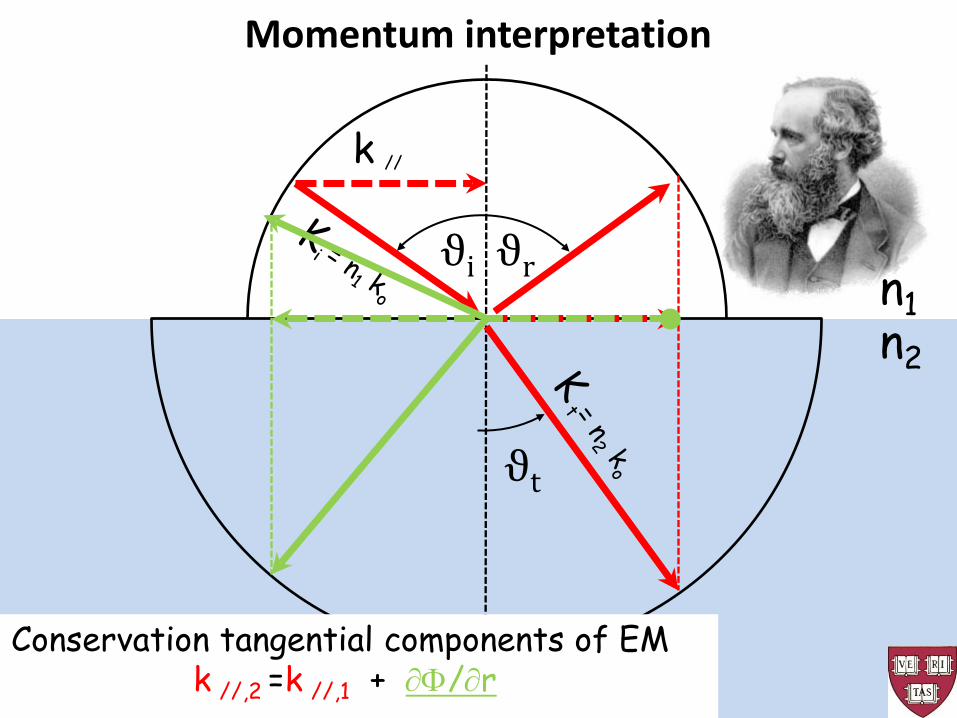
ϑr ϑi
ϑt
n1 n2
k //
Momentum interpretation
Conservation tangential components of EM k //,2 =k //,1
ϑr ϑi
ϑt
n1 n2
k //
Conservation tangential components of EM k //,2 =k //,1 + ∂Φ/∂r
Momentum interpretation
What about the polarization response of these interfaces ?
N Yu*, F Aieta*, P Genevet*, M A. Kats, Z Gaburro, F Capasso, Nano Lett., 12, 6328−6333 (2012)
A Broadband, Background-Free Quarter-Wave Plate Based on Plasmonic Metasurfaces
Go beyond the basic manipulation of reflection
and refraction of light ?
Linear phase gradients: Generalization of the laws of reflection and
refraction
N. Yu, P. Genevet , M. A. Kats, F. Aieta, J.-P. Tetienne, F. Capasso, Z. Gaburro, Science 334,333 (2011)
Presenter
Presentation Notes
Instead of a linear phase distribution, we can instead arrange the 8 antennas in such a way to imprint a spiral phase distribution to the planar incident wavefront. In this way we can created optical vortices.
Go beyond the basics manipulation of
reflection and refraction of light ?
• Angular arrangements of antennas create optical vortices
Linear phase gradients: Generalization of the laws of reflection and
refraction
N. Yu, P. Genevet , M. A. Kats, F. Aieta, J.-P. Tetienne, F. Capasso, Z. Gaburro, Science 334,333 (2011)
Presenter
Presentation Notes
Instead of a linear phase distribution, we can instead arrange the 8 antennas in such a way to imprint a spiral phase distribution to the planar incident wavefront. In this way we can created optical vortices.
WHAT’S THE BIG DEAL ???
Amplitude
Phase
0.2 µm 1 µm 2 µm 3.5 µm 8 µm
Distance from interface
Desired phase distribution is imprinted at the interface, creating phase changes over a subwavelength propagation distance. Ultra-thin plasmonic optical vortex plate based on phase discontinuities
P. Genevet et al., APL 100, 13101 (2012)
Presenter
Presentation Notes
One important feature of our plasmonic interface is that the desired phase distribution is imprinted on the incident wavefront immediately. These are simulations of the evolution of a vortex beam. At only one 1um away from the interface, one starts to see the feature of the vortex, which is the null at the center of the beam and the spiral phase distribution. Remember the wavelength is about 8 um.
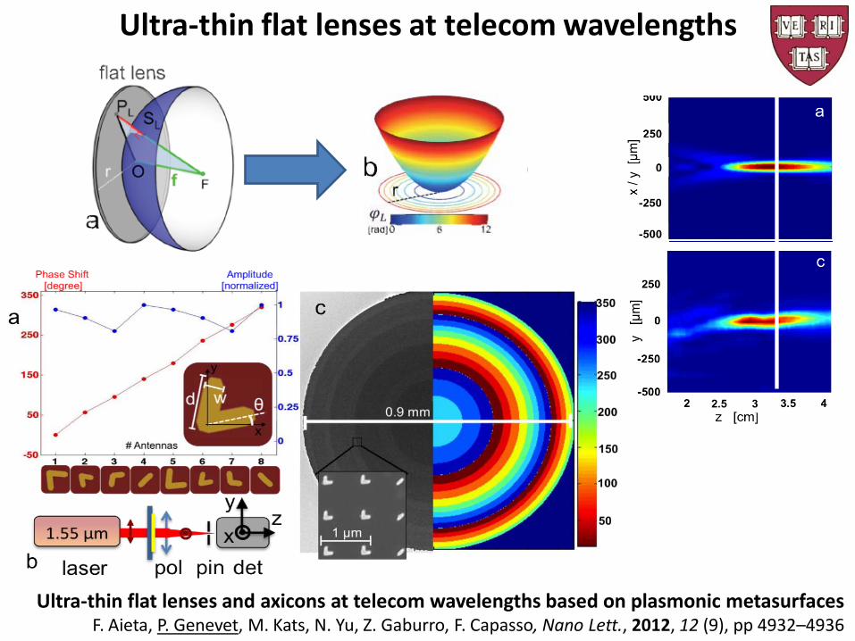
Ultra-thin flat lenses at telecom wavelengths
Ultra-thin flat lenses and axicons at telecom wavelengths based on plasmonic metasurfaces F. Aieta, P. Genevet, M. Kats, N. Yu, Z. Gaburro, F. Capasso, Nano Lett., 2012, 12 (9), pp 4932–4936
Ultra-thin flat lenses at telecom wavelengths
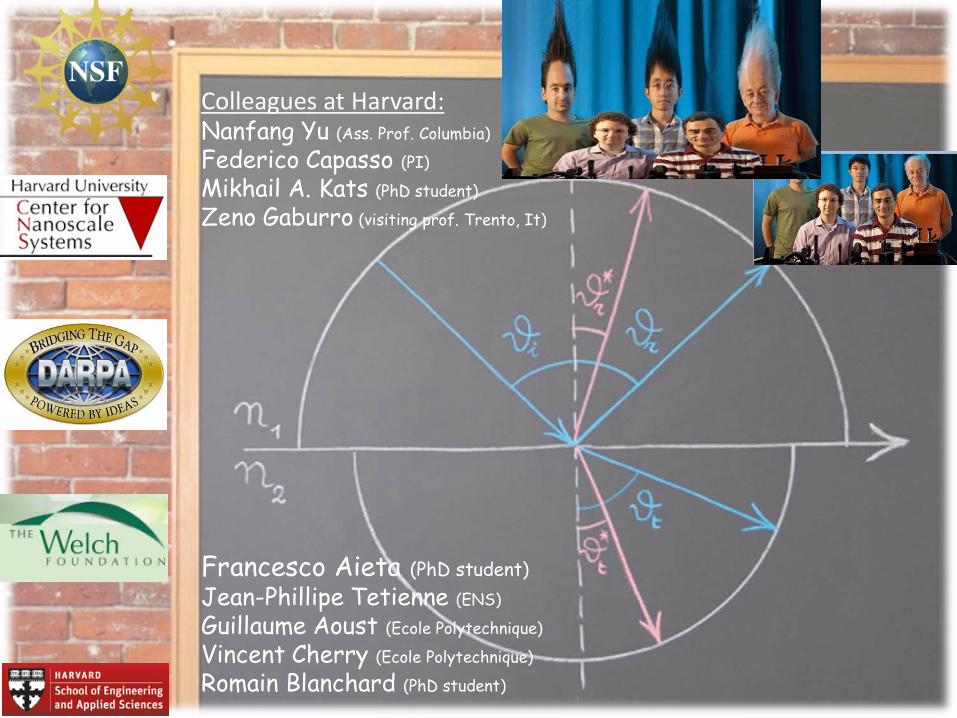
Colleagues at Harvard: Nanfang Yu (Ass. Prof. Columbia)
Federico Capasso (PI)
Mikhail A. Kats (PhD student)
Zeno Gaburro (visiting prof. Trento, It)
Francesco Aieta (PhD student)
Jean-Phillipe Tetienne (ENS)
Guillaume Aoust (Ecole Polytechnique)
Vincent Cherry (Ecole Polytechnique)
Romain Blanchard (PhD student)
Photonic Spin Hall Effect at Metasurfaces Xiaobo Yin et al., Science 339, 1405 (2013)
Basically, for each point on the object I have to find a path from the point to the mirror and to the observer that has the smallest accumulated optical phase. This of curse should include the phase jump on the surface of the mirror. And in the presence of such phase jumps the angle of reflection is almost always not equal to the incident angle. Some times you can even see negative reflection. Then I did back tracing of the reflected light to find the image point. This should be repeated for all the points on the object. Now you can see that the image is not only displaced but also deformed compared to the object.
-45o
0o
45o
90o
Dual-mode operation of a V-antenna solves the amplitude PB
Presenter
Presentation Notes
The motivation of using V-antenna is that it has two resonances and each resonance is associated with a phase shift of pi, bringing the total phase shift to be close to 2pi. A phase shift ranging from 0 to 2pi is important because this allows one to have the complete control over the phase and therefore the complete control over the wavefront of the scattered light. If you observe carefully, for the symmetric mode, the color map changes from dark blue to white, which is about -135 to 0 degrees. Whereas for the antisymmetric mode the color changes from white to dark magenta, that is from zero to pi. So the total phase shift is close to 2pi. We analytically calculate the amplitude and the phase response of the V-antenna as a function of the arm length h and the angle between the arms Delta for a fixed wavelength of 8 um. This is the amplitude of the scattered light polarized in the horizontal direction. And This is the phase of the scattered light polarized in the horizontal dierction. Here shown in dashed curves are the two antenna modes we have just discussed and indeed the resonant lengths of the antenna arm differ by approximately a factor of two. This is how we construct the metainterface. We choose these 4 antennas which have almost the same scattering amplitude and their phase response increases by a factor of 45 deg or pi/4. In total they cover a phase shift of pi.
Einc
Es Ea
Symmetric mode Antisymmetric mode
Einc
Ea Es
Es
Es Ea
Ea
Horizontal components of the antenna currents in opposite direction Horizontal components of the antenna emission π out of phase
Original
Mirror structure
Eout
Mirrored structures to extend the phase to the 2π range
Presenter
Presentation Notes
To obtain the other pi phase coverage, we use mirror structures. You can see that for the same incident polarization, the antenna current flows in opposite directions in the original and the mirror structure. As a result the horizontal components of the antenna reemission are pi out of phase. That is to say we can gain an extra pi phase shift by just flipping the antenna upside down.
-45o
0o
45o
90o
-45o 0o 45o 90o 135o 180o 225o 270o
Eight-element unit cell: full 2 coverage with identical scattering amplitude
Mirror structure
Presenter
Presentation Notes
And this is how we arrive at the 8 antenna unit cell. They have a phase coverage of 2pi with incremental phase of pi/4. In addition, they have equal scattering amplitudes.
Purity of vortex beams generated by our plasmonic phase arrays
Presenter
Presentation Notes
We analyzed the purity of the vortex beam with L=1 and found it is more than 90% pure. The process of the quantitative analysis is like this. The interference pattern is basically like a hologram: it contains not only the intensity information but also the phase information of the vortex beam. By doing Fourier transformation, we can recover the phase distribution. The amplitude of the vortex beam has beam recorded directly. Now we have all the information and we just decompose this complex wavefront on a basis set with different topological charges. And finally we can generate this histogram.
Phase
Amplitude
Purity of vortex beams comparable to those generated by SLMs
Quantitative analysis
The interference pattern is basically like a
hologram which contains both intensity and phase
informations.
Decompose this complex wavefront on a basis set with
topological charges
Presenter
Presentation Notes
We analyzed the purity of the vortex beam with L=1 and found it is more than 90% pure. The process of the quantitative analysis is like this. The interference pattern is basically like a hologram: it contains not only the intensity information but also the phase information of the vortex beam. By doing Fourier transformation, we can recover the phase distribution. The amplitude of the vortex beam has beam recorded directly. Now we have all the information and we just decompose this complex wavefront on a basis set with different topological charges. And finally we can generate this histogram.
in-plane component
out-of-plane component
Pi , dr , Pt are non-coplanar
Out of plane reflection and refraction of light with metasurfaces F. Aieta, P. Genevet, N. Yu, M. Kats, Z. Gaburro, F. Capasso,
Nano Letters 12, 1702−1706 (2012)
Phase Gradient arbitrarily oriented
0 2 4 cm
Planar Focusing Lenses and Axicons Metasurfaces
Aberration-free ultra-thin flat lenses and axicons at telecom wavelengths based on plasmonic metasurfaces
F. Aieta, P. Genevet, M. Kats, N. Yu, Z. Gaburro, F. Capasso,Nano Letters accepted for publication (2012)