Embed Size (px)
Citation preview

Nanomechanics, Inc.
iNano Indentation System Operating Instructions
SKYD-0892-0

Nanomechanics, Inc. iNano Indentation System Operating Instructions
2
Contents 1.0 Introduction ............................................................................................................................................ 5
1.1 About Nanomechanics ........................................................................................................................ 5
1.2 Contacting Us ...................................................................................................................................... 5
1.3 Unpacking ........................................................................................................................................... 7
2.0 About the iNano ...................................................................................................................................... 8
2.1 Overview of the System ...................................................................................................................... 8
3.0 Getting Started ........................................................................................................................................ 9
3.1 Getting Started .................................................................................................................................... 9
3.2 Before Running Tests .......................................................................................................................... 9
3.3 Running Tests .................................................................................................................................... 10
3.4 Reviewing Data ................................................................................................................................. 19
4.0 Commonly Used Procedures ................................................................................................................. 28
4.1 Operational Check ............................................................................................................................. 28
4.2 Loading Specimens ............................................................................................................................ 36
4.2.1 Loading Specimens ..................................................................................................................... 36
4.2.2 The Visual Method ..................................................................................................................... 37
4.2.3 The Mechanical Method ............................................................................................................ 38
4.3 Video Source Calibration ................................................................................................................... 41
4.3.1 Preparing for the calibrations .................................................................................................... 42
4.3.2 Field of View Calibration ............................................................................................................ 45
4.3.3 Video Source Calibration............................................................................................................ 54
4.4 Tip Change ......................................................................................................................................... 58
4.4.1 Removing the Tip ....................................................................................................................... 58
4.4.2 Installing a Tip ............................................................................................................................ 66

Nanomechanics, Inc. iNano Indentation System Operating Instructions
3
4.5 Advanced Tip Calibration .................................................................................................................. 71
5.0 Hardware Reference ............................................................................................................................. 87
5.1 Overview of the System .................................................................................................................... 87
5.2 Description of Components .............................................................................................................. 89
5.2.1 Actuator ..................................................................................................................................... 89
5.2.2 Aluminum Specimen .................................................................................................................. 90
5.2.3 Cabinet ....................................................................................................................................... 90
5.2.4 Controller ................................................................................................................................... 91
5.2.5 Extension Axis (Z Axis) ................................................................................................................ 91
5.2.6 Fused Silica Specimen ................................................................................................................ 92
5.2.7 Gantry ........................................................................................................................................ 92
5.2.8 Microscope ................................................................................................................................. 92
5.2.9 Motion System (X & Y Axes) ....................................................................................................... 92
5.2.10 Puck .......................................................................................................................................... 93
5.2.11 Sample Tray .............................................................................................................................. 93
5.2.12 Tip............................................................................................................................................. 93
5.2.13 Tip Change Pins ........................................................................................................................ 93
5.2.14 Vibration Isolation .................................................................................................................... 94
6.0 Software Reference .............................................................................................................................. 95
6.1 The CPU & Operating Software ......................................................................................................... 95
6.2 Key terminology ................................................................................................................................ 96
6.3 InView Test Program ......................................................................................................................... 98
6.3.1 Opening InView Test Program ................................................................................................... 98
6.3.2 Top Bar ..................................................................................................................................... 100

Nanomechanics, Inc. iNano Indentation System Operating Instructions
4
6.3.3 Meters Pane ............................................................................................................................. 106
6.3.4 Motion Control Pane ................................................................................................................ 110
6.3.5 Video Pane .............................................................................................................................. 119
6.3.6 Real Time Graph ....................................................................................................................... 129
6.3.7 MultiSample Test Definition .................................................................................................... 132
6.4 InView Review Program .................................................................................................................. 142
6.4.1 InView Opening ........................................................................................................................ 142
6.4.2 Top Bar ..................................................................................................................................... 145
6.4.3 Test Selection Pane .................................................................................................................. 159
6.4.4 Test Parameters Pane .............................................................................................................. 160
6.4.5 Results Pane ............................................................................................................................. 160
6.4.6 Plot Pane .................................................................................................................................. 162
6.5 References ...................................................................................................................................... 170
6.5.1 Channels ................................................................................................................................... 170

Nanomechanics, Inc. iNano Indentation System Operating Instructions
5
1.0 Introduction
1.1 About Nanomechanics
A word about us: Nanomechanics, Incorporated is comprised of scientists and engineers with
unparalleled expertise in Materials Science, Precision Mechanical Design, and Advanced Instrumentation
Software. Over the last 20 years, our staff has stayed at the forefront of technology focused on nano-
scale mechanical testing. We take a comprehensive approach to developing quality solutions for our
customers.
We are dedicated to improving technologies in mechanical testing, force and displacement
measurements, and evaluating the mechanical performance of materials. We do this through the
research and development of test techniques and data management, design and manufacturing, and
through our state-of-the-art analytical services laboratory. Our engineers specialize in nanomechanical
transducer design, testing techniques, data acquisition, system integration, and software development.
Our principle mission is to enable our customers to evaluate and understand the mechanical
performance of their materials on the micro- and nano-scales. With field experts in nanomechanical
testing, data acquisition, and system integration, we are well positioned to provide the operator with
the most accurate results along with leading edge characterization.
1.2 Contacting Us
Getting More Information about Nanomechanics, Inc. and Our Products
To find out more about Nanomechanics, Inc. and our products, visit the NanoMechanics, Inc. website at
http://www.insem.com/.
An online Contact Us form can be obtained at this link – one of our application engineers will contact
you regarding your request within 24 hours.
For direct contact by phone, call 1-877-386-6262.
Additionally, you may email us at: [email protected].

Nanomechanics, Inc. iNano Indentation System Operating Instructions
6
Our mailing address is:
Nanomechanics, Inc. 105 Meco Lane, Suite 100 Oak Ridge, TN 37830 USA
You can find us on social media at:
Facebook: https://www.facebook.com/pages/Nanomechanics-Inc/124992837512793 Twitter: https://twitter.com/Nanomechanics LinkedIn: http://www.linkedin.com/company/549484?trk=tyah&trkInfo=tas%3Ananomechani%2Cidx%3A1-1-1 YouTube – our channel on YouTube is titled NanoInSEM: http://www.youtube.com/user/NanoInSEM
YouTube – Nanomechanics, Inc. Introduction to InSEM:
http://www.youtube.com/watch?v=KwiVZ6t2O2M
Contacting Technical Support and Sales Support
What you will need before you call
Before calling for technical support, have the following information on hand:
Machine number
Software Version (See Section 6.3.3.1)
Description of problem
Data from Operational Check (see Section 4.1)
Method
Tip (Type, Geometry)
Sample Information
Technical Support email: [email protected]
Technical Support phone: 877-386-6262

Nanomechanics, Inc. iNano Indentation System Operating Instructions
7
A note to our overseas customers
Overseas customers should contact their local representative first.
To access a list of representatives, you may email us at [email protected], or go to the Contact Us
(http://www.nanomechanicsinc.com/distributors) page on our website.
Training Classes
Nanomechanics, Inc. offers periodic training classes for our products as well as training by request.
Basic training is provided when your system is installed. For more information regarding our training
services, visit our website training information page:
http://www.nanomechanicsinc.com/training
1.3 Unpacking
Unpacking and Installing the iNano
The iNano is a “self-installed” system, meaning that in almost all cases, the user can unpack and install
the system without the requirement of an on-site installation by Nanomechanics personnel.
Refer to the unpacking and installation instructions in document SKYD-0758-0 iNano Indentation
Unpacking System, which is located in the “Open Me First” box of the iNano shipment.

Nanomechanics, Inc. iNano Indentation System Operating Instructions
8
2.0 About the iNano
2.1 Overview of the System About the iNano:
The iNano can be best described as a “mechanical properties microprobe.” Simply speaking, it is a
device for measuring the mechanical properties of materials, structure, or devices. The iNano applies
highly resolved forces and measures sub-nanometer displacements and stiffness. Utilizing the force and
displacement data, along with the stiffness, the properties of a specimen can be determined through a
variety of analytic models.
The iNano consists of a number of subsystems:
Computer (CPU)
Isolation Cabinet
Microscope
Gantry
Motion System
Sample Tray
InQuest Controller
InForce 50 Head
InView Software
The iNano operates in the following manner: The user mounts specimens to “pucks” which are then
loaded into a sample tray, which is in turn loaded into the iNano. By operating the InView software on
the CPU, the user can utilize the motion system to move the specimens under the microscope, and
select target locations for tests to be performed. After a test method is selected and the desired test
locations are chosen, the tests are performed automatically. When the tests are done, the data is
presented in the Review Data program of the InView software, where analysis can be performed or the
data exported.
The most typical use of the iNano is in performing indentation tests. There are many resources for
understanding indentation. Please contact Nanomechanics if you would like recommendations for
indentation tutorials or training.
Nanomechanics, Inc. iNano Indentation System Operating Instructions
9
3.0 Getting Started
3.1 Getting Started This section of the manual guides the user through performing indentations on two different specimens,
using a MultiSample test setup, and subsequent data review. Completion of these procedures should
provide the user with a basic familiarity with the iNano and its operation. Some of the steps covered in
this procedure are somewhat arbitrary, haven been chosen to introduce aspects of instrument
operation and data analysis, rather than being steps that the user will perform during routine operation.
Training in advanced operation of the iNano is available from Nanomechanics.
3.2 Before Running Tests Before running any tests, make sure that the Unpacking & Setup instructions have been completely
followed, including performing the Operational Check (see Section 4.1). Refer to the Unpacking
Instruction document that was provided with the system (contact Nanomechanics if a new copy of this
document is required). It is important that the instrument be properly set-up before running the
following procedure. This procedure presupposes, among other criteria, that the “shipping rails” have
been removed, the Tip Change Pins are not in the Actuator (see Section 4.4), the motion system is
initialized, etc.
Finally, it is a good idea to read the Hardware Reference and Software Reference sections of this
manual, as well as the Commonly Used Procedures. The following procedure directs the user to the
appropriate sections of the manual, but a good overview of the system is helpful to improve
understanding of the various operations performed.
Nanomechanics, Inc. iNano Indentation System Operating Instructions
10
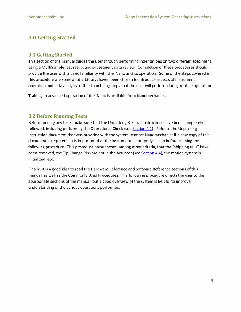
3.3 Running Tests Open the InView Test software on the Computer (see Section 6.3.1).
The InView Test software will open, and will ask for a method to be loaded. Select the method
“Dyn.Indentation-Const.Strain Rate” in the Master Methods folder.
Figure 1 – Select Method
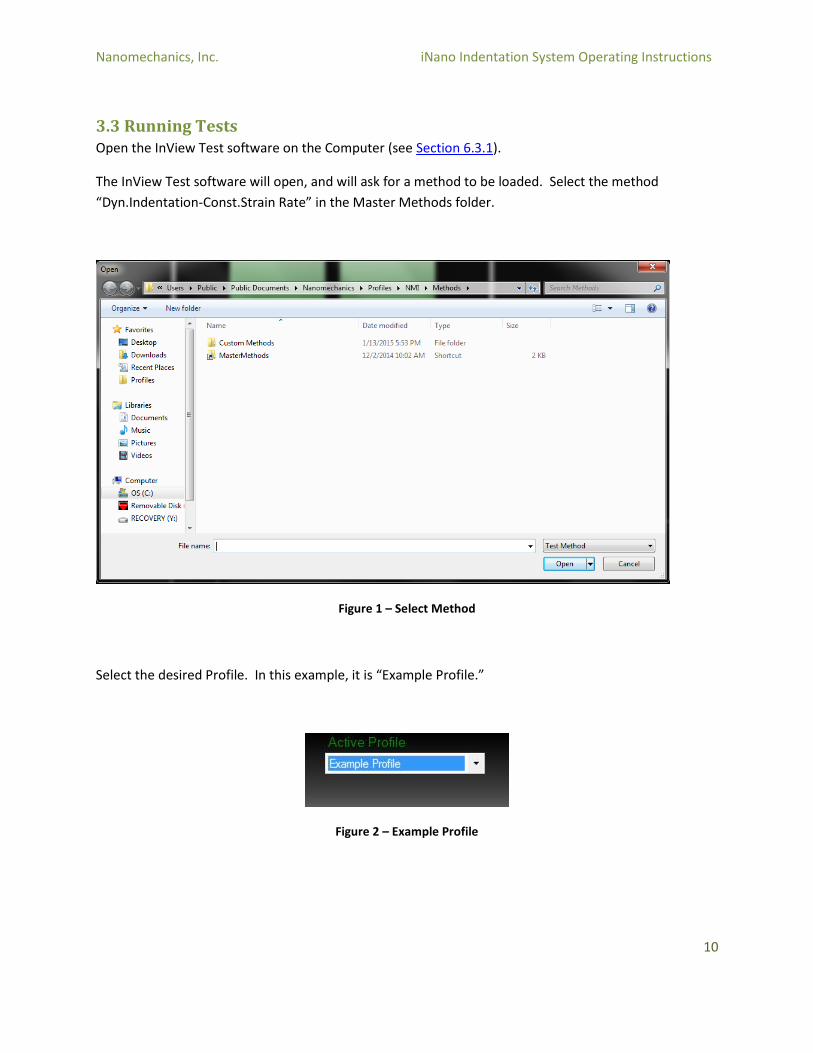
Select the desired Profile. In this example, it is “Example Profile.”
Figure 2 – Example Profile
Nanomechanics, Inc. iNano Indentation System Operating Instructions
11
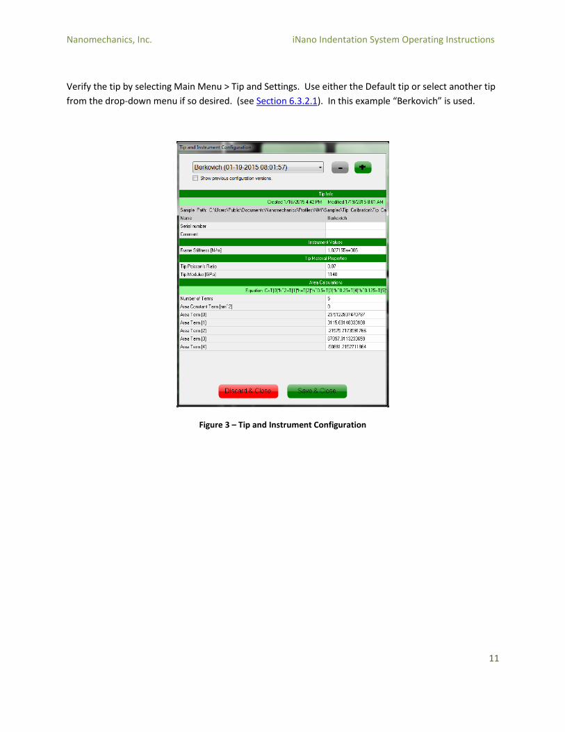
Verify the tip by selecting Main Menu > Tip and Settings. Use either the Default tip or select another tip
from the drop-down menu if so desired. (see Section 6.3.2.1). In this example “Berkovich” is used.
Figure 3 – Tip and Instrument Configuration
Nanomechanics, Inc. iNano Indentation System Operating Instructions
12
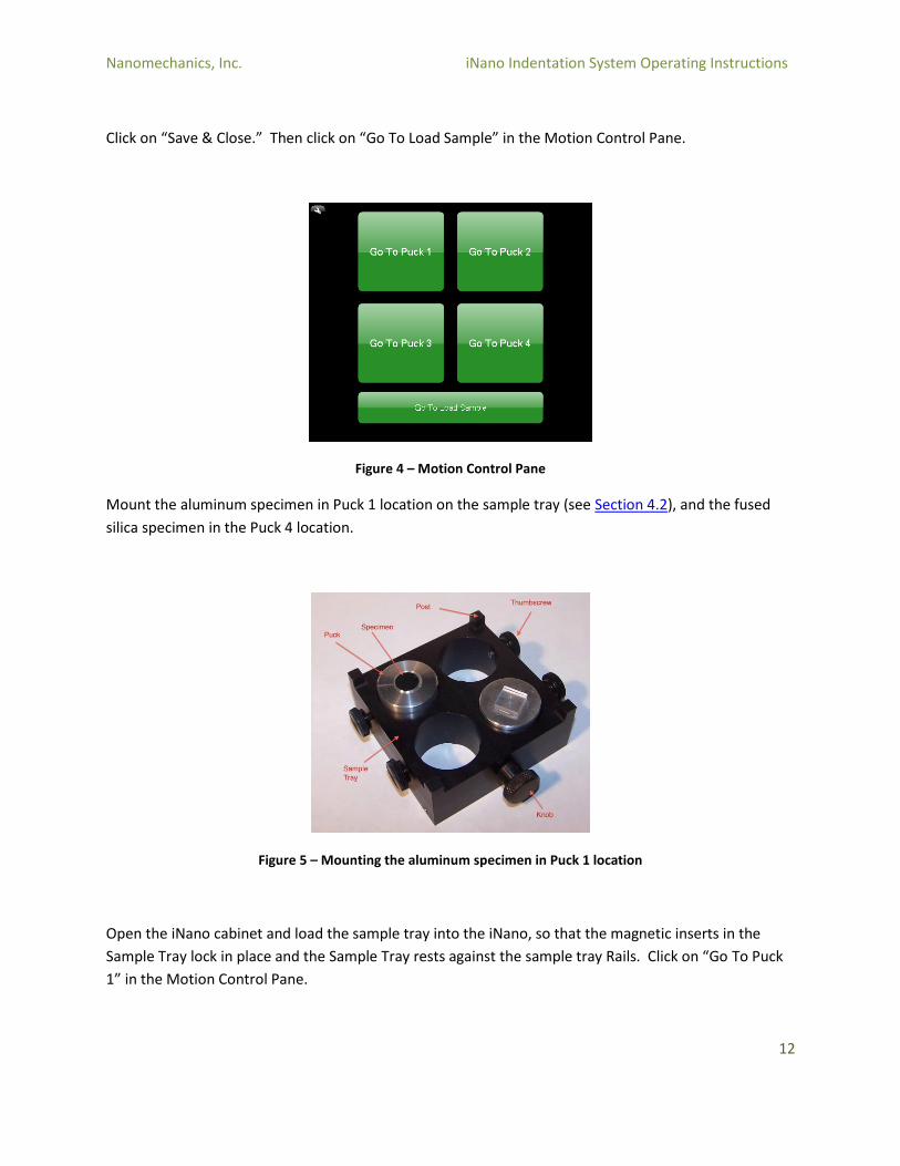
Click on “Save & Close.” Then click on “Go To Load Sample” in the Motion Control Pane.
Figure 4 – Motion Control Pane
Mount the aluminum specimen in Puck 1 location on the sample tray (see Section 4.2), and the fused
silica specimen in the Puck 4 location.
Figure 5 – Mounting the aluminum specimen in Puck 1 location
Open the iNano cabinet and load the sample tray into the iNano, so that the magnetic inserts in the
Sample Tray lock in place and the Sample Tray rests against the sample tray Rails. Click on “Go To Puck
1” in the Motion Control Pane.

Nanomechanics, Inc. iNano Indentation System Operating Instructions
13
Use the microscope to focus on the surface of the aluminum specimen (see Section 6.3.5). Right-click on
the video image and turn on Annotations > Test Locations, Sample Name, and Scale. Locate an area of
the specimen where the indents should be placed (try to find a clear area of the sample with minimal
scratches or debris). Note that you can move the specimen relative to the microscope by dragging the
cursor across the video screen, or by clicking on a desired location on the video screen.
Figure 6 - Annotations
Nanomechanics, Inc. iNano Indentation System Operating Instructions
14
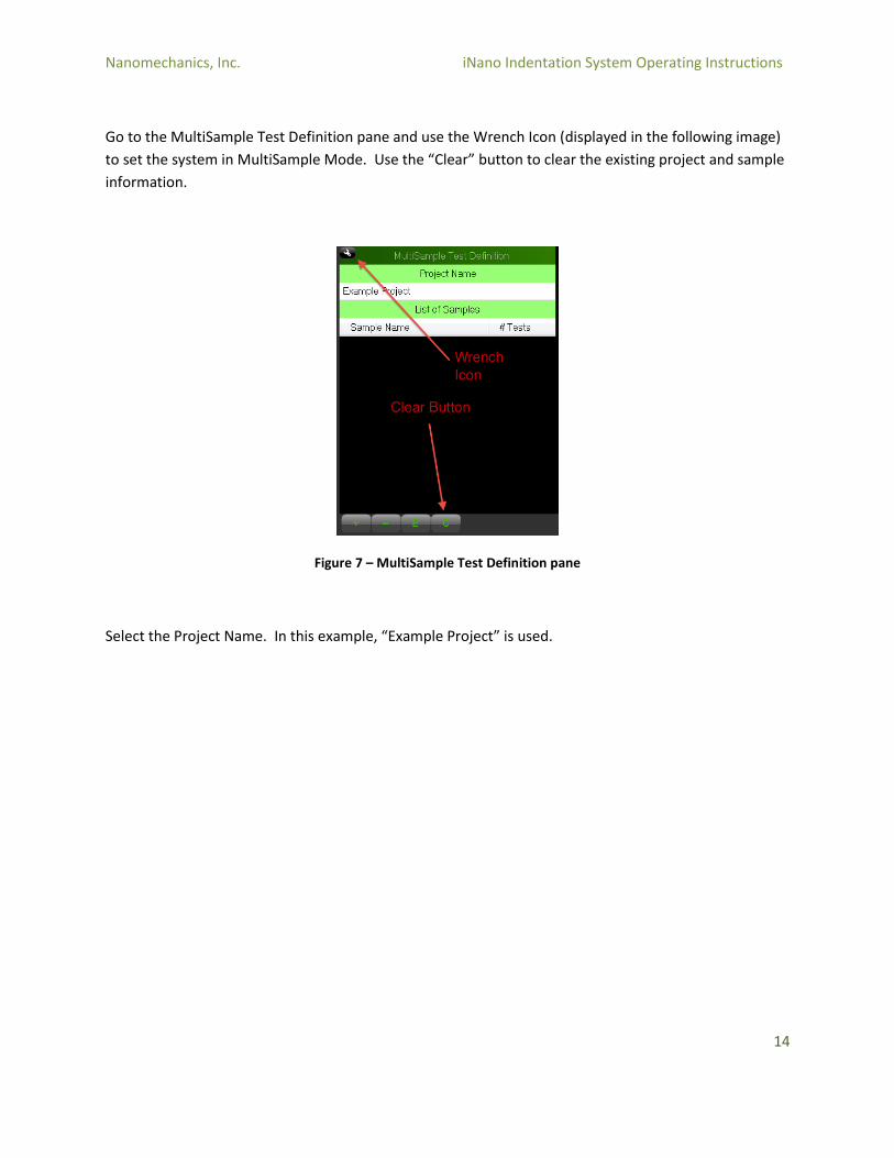
Go to the MultiSample Test Definition pane and use the Wrench Icon (displayed in the following image)
to set the system in MultiSample Mode. Use the “Clear” button to clear the existing project and sample
information.
Figure 7 – MultiSample Test Definition pane
Select the Project Name. In this example, “Example Project” is used.

Nanomechanics, Inc. iNano Indentation System Operating Instructions
15
Click on the (+) button to add a Sample. Enter the Sample Name. For this first (aluminum) specimen,
the Sample Name “Aluminum” is used. It is also a good practice to review the Method and ensure that
it is the desired Method.
Figure 8 – MultiSample Add Sample pane
Click on the Next Step button (>). Do not change any of the defaults on the Sample Level Inputs or Test
Level Inputs. Click on the Next Step button (>).
Nanomechanics, Inc. iNano Indentation System Operating Instructions
16
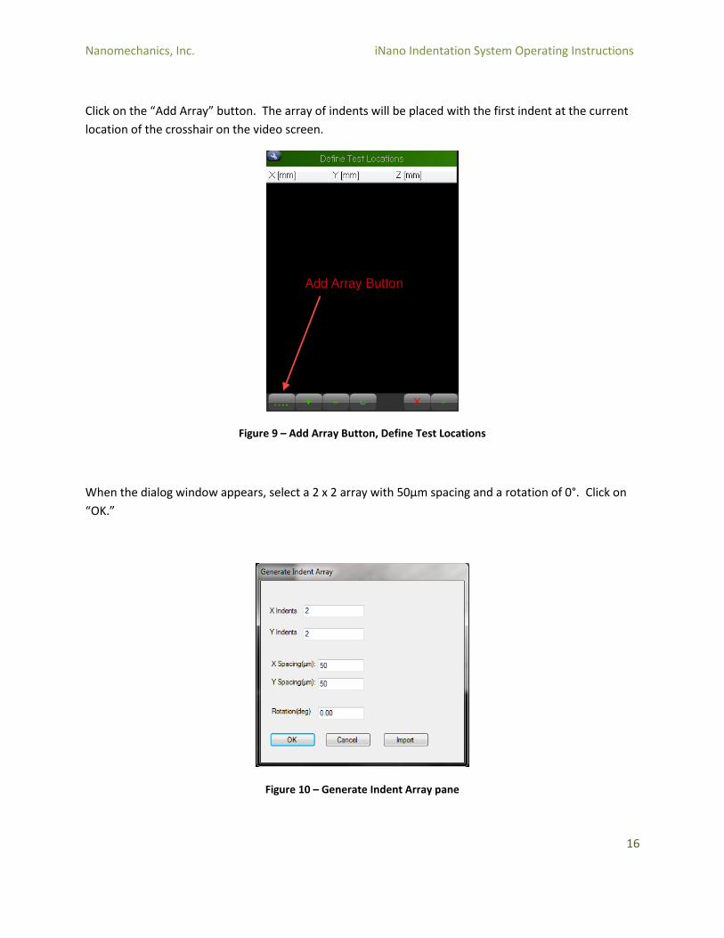
Click on the “Add Array” button. The array of indents will be placed with the first indent at the current
location of the crosshair on the video screen.
Figure 9 – Add Array Button, Define Test Locations
When the dialog window appears, select a 2 x 2 array with 50µm spacing and a rotation of 0°. Click on
“OK.”
Figure 10 – Generate Indent Array pane

Nanomechanics, Inc. iNano Indentation System Operating Instructions
17
Click on the “Next Step” button (>). Add another Sample by clicking on the (+) button. Enter the Sample
Name. For this second (fused silica) specimen, the Sample Name “Fused Silica” is used.
Click on the Next Step button (>). Do not change any of the defaults on the Sample Level Inputs or Test
Level Inputs. Click on the Next Step button (>).
Click on the “Go to Puck 4” button in the Motion Control Pane. When the move is completed, use the
Microscope to focus on the surface of the fused silica specimen (see Section 6.3.5). Locate an area of
the specimen where the indents should be placed (try to find a clear area of the sample with minimal
scratches or debris).
Click on the “Add Array” button. The array of indents will be placed with the first indent at the current
location of the crosshair on the video screen.
When the dialog window appears, select a 3 x 3 array with 20µm spacing and a rotation of 0°. Click on
“OK.”
Click on the “Next Step” button (>). Add another Sample by clicking on the (+) button. Enter a new
Sample Name. In this case, a third Sample will be added, but on the same specimen (fused silica) and
using a different method. In this example, the Sample Name “Fused Silica Cycles” is used. Click on the
Method and select “Cyclic Indentation To A Load” from the Master Methods folder.
Figure 11 – MultiSample Add Sample pane
Click on the Next Step button (>). Do not change any of the defaults on the Sample Level Inputs or Test
Level Inputs. Click on the Next Step button (>).
Nanomechanics, Inc. iNano Indentation System Operating Instructions
18
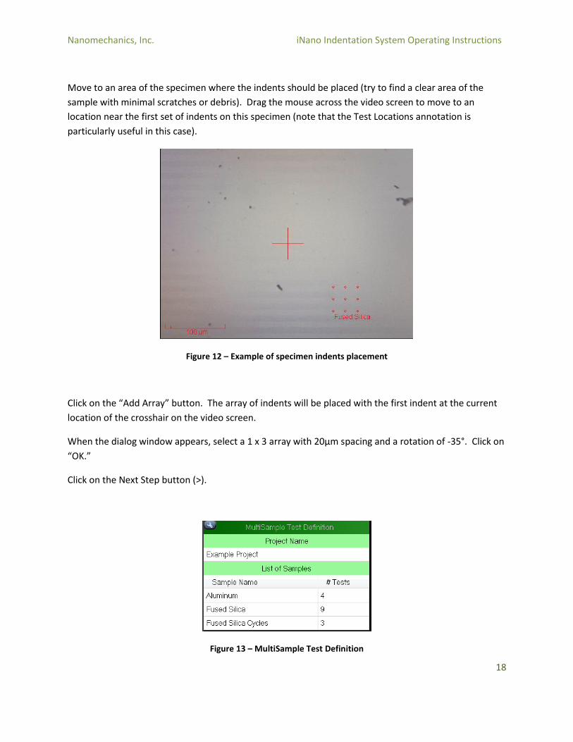
Move to an area of the specimen where the indents should be placed (try to find a clear area of the
sample with minimal scratches or debris). Drag the mouse across the video screen to move to an
location near the first set of indents on this specimen (note that the Test Locations annotation is
particularly useful in this case).
Figure 12 – Example of specimen indents placement
Click on the “Add Array” button. The array of indents will be placed with the first indent at the current
location of the crosshair on the video screen.
When the dialog window appears, select a 1 x 3 array with 20µm spacing and a rotation of -35°. Click on
“OK.”
Click on the Next Step button (>).
Figure 13 – MultiSample Test Definition

Nanomechanics, Inc. iNano Indentation System Operating Instructions
19
Close the iNano cabinet. Click on the green “Run” button to start the test.
The tests will take approximately one hour to complete (depending on how quickly the instrument
meets the thermal drift criterion). While the test is running, note the initial hold for thermal drift before
the indents begin. Once the first test starts, note the log window (see Section 6.3.2.5) and the Real Time
Graph. Also observe the Method, Sample, and Test Information on the top bar, which shows the current
sample and test. After the first indentation is complete, the Sample will change from (Not Saved) to
“Aluminum,” which is the first sample on the MultiSample test run.
3.4 Reviewing Data As each Test is completed, the data becomes available in the InView Review program. For this
procedure, however, it is desirable to wait until all Samples are complete before reviewing data. Once
the tests are all complete, open InView Review program by selecting the InView Review icon from the
bottom tool bar.
Figure 14 – InView Review icon, bottom tool bar
Click on the “New Data Available” notification at the top of the Review page. It may take a moment for
the software to load the data and display it.
Figure 15 – New Data Available notification, Review page
By default, the Sample that is loaded is the last Sample in the MultiSample test run, in this case “Fused
Silica Cycles.”
Ensure that the Profile is set to “Example Profile”
Figure 16 – Active Profile set to Example Profile
Nanomechanics, Inc. iNano Indentation System Operating Instructions
20
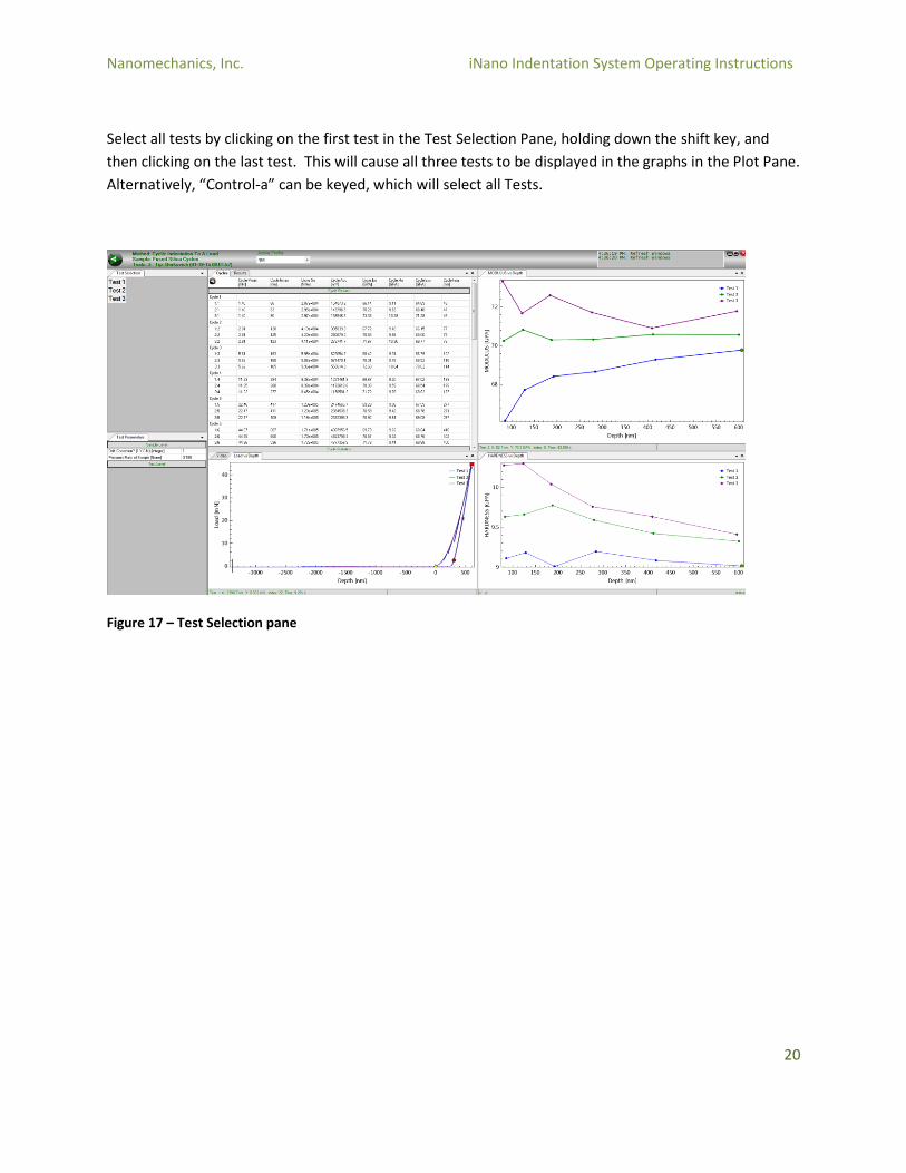
Select all tests by clicking on the first test in the Test Selection Pane, holding down the shift key, and
then clicking on the last test. This will cause all three tests to be displayed in the graphs in the Plot Pane.
Alternatively, “Control-a” can be keyed, which will select all Tests.
Figure 17 – Test Selection pane
Nanomechanics, Inc. iNano Indentation System Operating Instructions
21
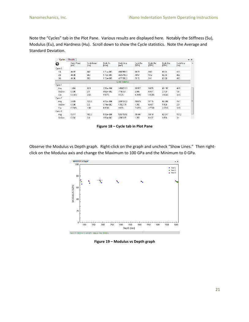
Note the “Cycles” tab in the Plot Pane. Various results are displayed here. Notably the Stiffness (Su),
Modulus (Eu), and Hardness (Hu). Scroll down to show the Cycle statistics. Note the Average and
Standard Deviation.
Figure 18 – Cycle tab in Plot Pane
Observe the Modulus vs Depth graph. Right-click on the graph and uncheck “Show Lines.” Then right-
click on the Modulus axis and change the Maximum to 100 GPa and the Minimum to 0 GPa.
Figure 19 – Modulus vs Depth graph
Nanomechanics, Inc. iNano Indentation System Operating Instructions
22
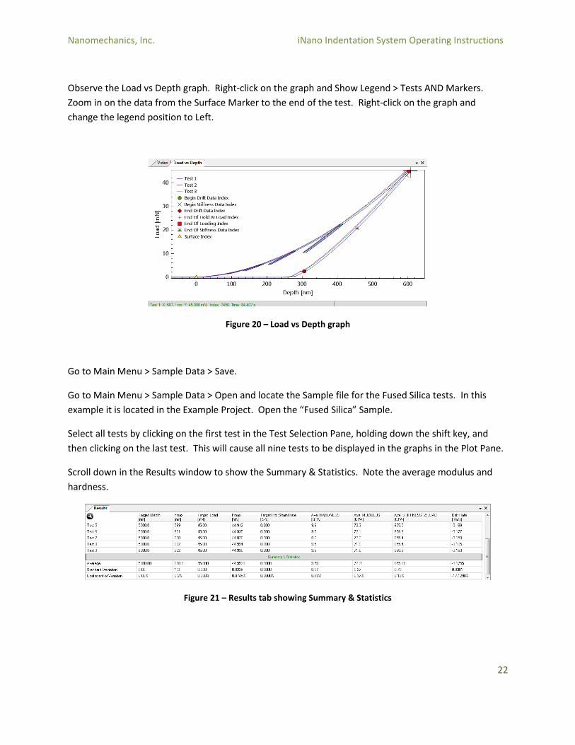
Observe the Load vs Depth graph. Right-click on the graph and Show Legend > Tests AND Markers.
Zoom in on the data from the Surface Marker to the end of the test. Right-click on the graph and
change the legend position to Left.
Figure 20 – Load vs Depth graph
Go to Main Menu > Sample Data > Save.
Go to Main Menu > Sample Data > Open and locate the Sample file for the Fused Silica tests. In this
example it is located in the Example Project. Open the “Fused Silica” Sample.
Select all tests by clicking on the first test in the Test Selection Pane, holding down the shift key, and
then clicking on the last test. This will cause all nine tests to be displayed in the graphs in the Plot Pane.
Scroll down in the Results window to show the Summary & Statistics. Note the average modulus and
hardness.
Figure 21 – Results tab showing Summary & Statistics
Nanomechanics, Inc. iNano Indentation System Operating Instructions
23
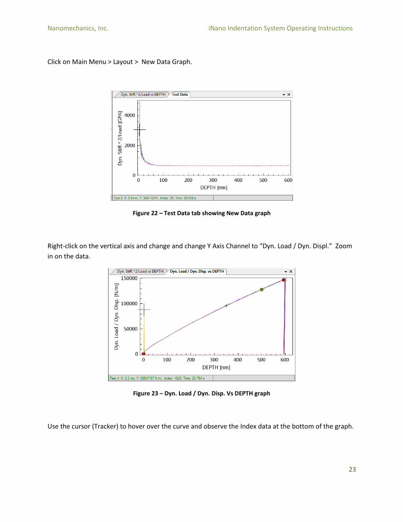
Click on Main Menu > Layout > New Data Graph.
Figure 22 – Test Data tab showing New Data graph
Right-click on the vertical axis and change and change Y Axis Channel to “Dyn. Load / Dyn. Displ.” Zoom
in on the data.
Figure 23 – Dyn. Load / Dyn. Disp. Vs DEPTH graph
Use the cursor (Tracker) to hover over the curve and observe the Index data at the bottom of the graph.
Nanomechanics, Inc. iNano Indentation System Operating Instructions
24
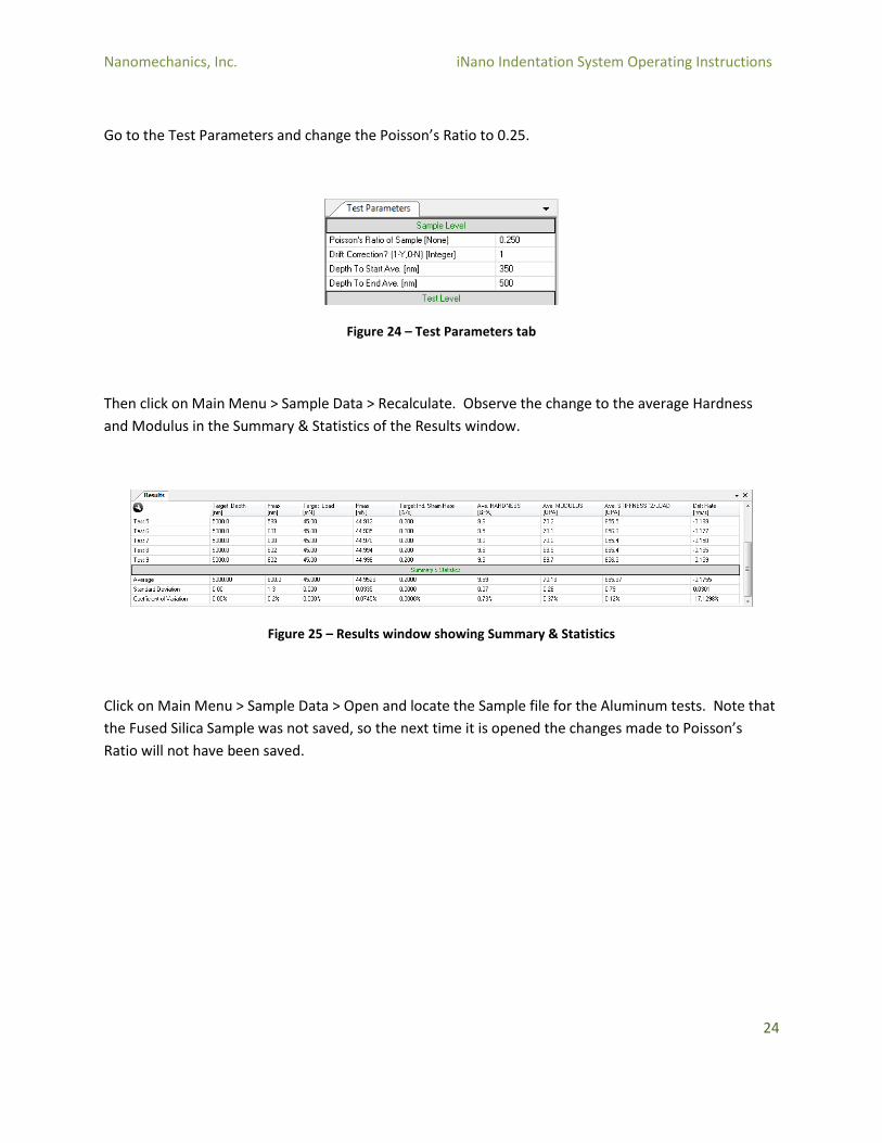
Go to the Test Parameters and change the Poisson’s Ratio to 0.25.
Figure 24 – Test Parameters tab
Then click on Main Menu > Sample Data > Recalculate. Observe the change to the average Hardness
and Modulus in the Summary & Statistics of the Results window.
Figure 25 – Results window showing Summary & Statistics
Click on Main Menu > Sample Data > Open and locate the Sample file for the Aluminum tests. Note that
the Fused Silica Sample was not saved, so the next time it is opened the changes made to Poisson’s
Ratio will not have been saved.
Nanomechanics, Inc. iNano Indentation System Operating Instructions
25
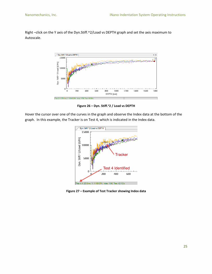
Right –click on the Y axis of the Dyn.Stiff.^2/Load vs DEPTH graph and set the axis maximum to
Autoscale.
Figure 26 – Dyn. Stiff.ᶺ2 / Load vs DEPTH
Hover the cursor over one of the curves in the graph and observe the Index data at the bottom of the
graph. In this example, the Tracker is on Test 4, which is indicated in the Index data.
Figure 27 – Example of Test Tracker showing Index data
Nanomechanics, Inc. iNano Indentation System Operating Instructions
26
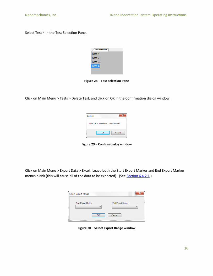
Select Test 4 in the Test Selection Pane.
Figure 28 – Test Selection Pane
Click on Main Menu > Tests > Delete Test, and click on OK in the Confirmation dialog window.
Figure 29 – Confirm dialog window
Click on Main Menu > Export Data > Excel. Leave both the Start Export Marker and End Export Marker
menus blank (this will cause all of the data to be exported). (See Section 6.4.2.1.)
Figure 30 – Select Export Range window

Nanomechanics, Inc. iNano Indentation System Operating Instructions
27
After completing all of these steps, the user should have a good familiarity with commonly performed
operations. As mentioned previously, it is a good idea to read through the Commonly Used Procedures,
Hardware Reference, and Software Reference sections of this manual.

Nanomechanics, Inc. iNano Indentation System Operating Instructions
28
4.0 Commonly Used Procedures
4.1 Operational Check
The Operational Check method is provided as a convenient way to ensure that the iNano is functioning
properly. The method moves the iNano actuator through its range of motion, and then analyzes that
motion for inconsistencies in the linearity and support spring stiffness of the actuator. If the Operational
Check is successful, there is a high degree of confidence that the iNano is performing to its required
specifications.
It is a good idea to run the Operational Check frequently, and to save the resultant sample files. If there
is a problem with the iNano, an Operational Check history can help diagnose the problem.
Close the iNano cabinet if it is not already closed.
From the main menu, select Test Method > Open
Figure 31 – Open a Test Method
Nanomechanics, Inc. iNano Indentation System Operating Instructions
29
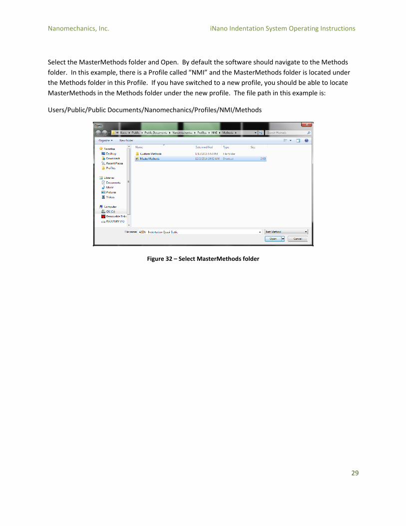
Select the MasterMethods folder and Open. By default the software should navigate to the Methods
folder. In this example, there is a Profile called “NMI” and the MasterMethods folder is located under
the Methods folder in this Profile. If you have switched to a new profile, you should be able to locate
MasterMethods in the Methods folder under the new profile. The file path in this example is:
Users/Public/Public Documents/Nanomechanics/Profiles/NMI/Methods
Figure 32 – Select MasterMethods folder
Nanomechanics, Inc. iNano Indentation System Operating Instructions
30
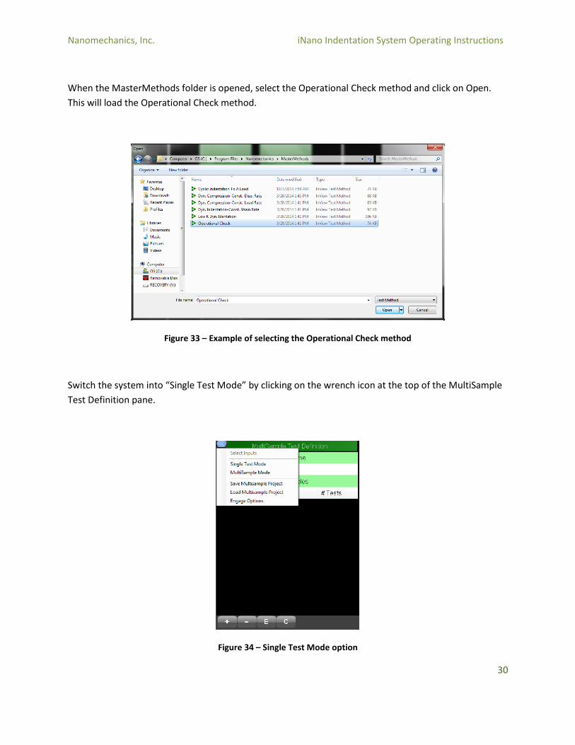
When the MasterMethods folder is opened, select the Operational Check method and click on Open.
This will load the Operational Check method.
Figure 33 – Example of selecting the Operational Check method
Switch the system into “Single Test Mode” by clicking on the wrench icon at the top of the MultiSample
Test Definition pane.
Figure 34 – Single Test Mode option
Nanomechanics, Inc. iNano Indentation System Operating Instructions
31
Click on the green Run button at the top of the screen.
Figure 35 – Green Run Button
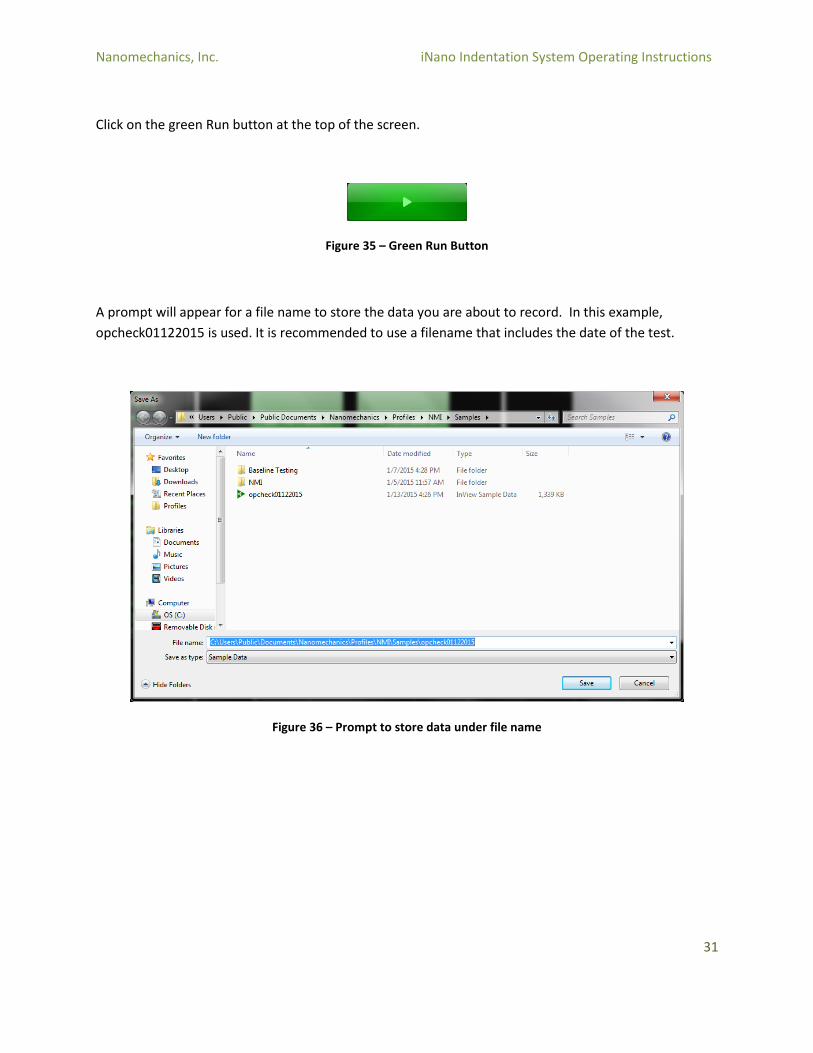
A prompt will appear for a file name to store the data you are about to record. In this example,
opcheck01122015 is used. It is recommended to use a filename that includes the date of the test.
Figure 36 – Prompt to store data under file name
Nanomechanics, Inc. iNano Indentation System Operating Instructions
32
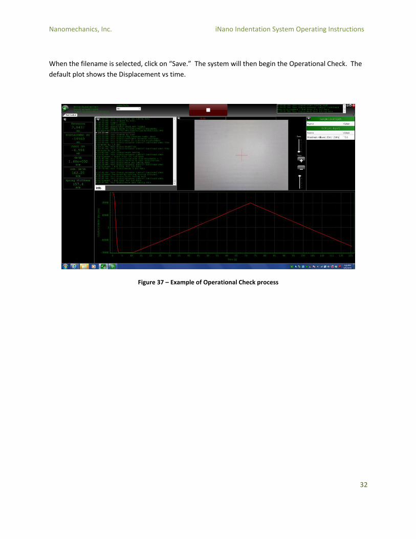
When the filename is selected, click on “Save.” The system will then begin the Operational Check. The
default plot shows the Displacement vs time.
Figure 37 – Example of Operational Check process
Nanomechanics, Inc. iNano Indentation System Operating Instructions
33
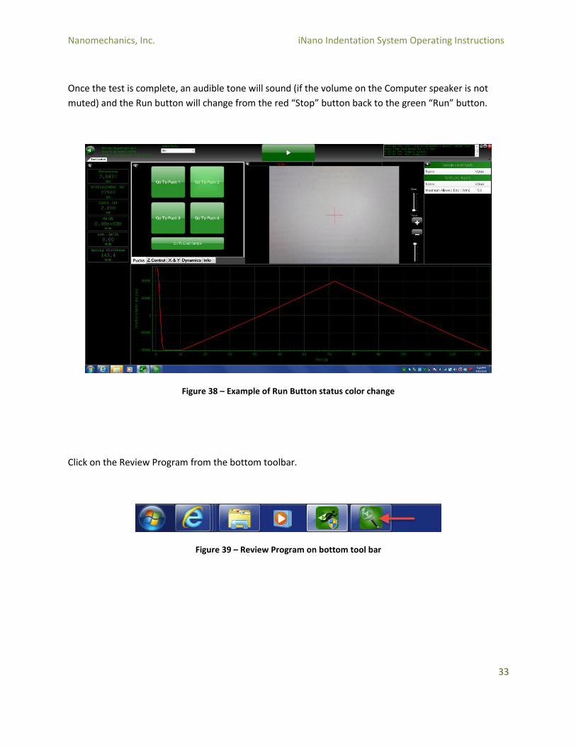
Once the test is complete, an audible tone will sound (if the volume on the Computer speaker is not
muted) and the Run button will change from the red “Stop” button back to the green “Run” button.
Figure 38 – Example of Run Button status color change
Click on the Review Program from the bottom toolbar.
Figure 39 – Review Program on bottom tool bar
Nanomechanics, Inc. iNano Indentation System Operating Instructions
34
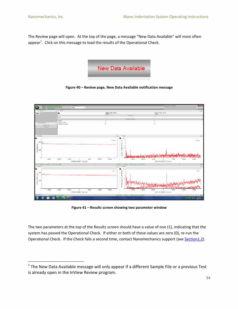
The Review page will open. At the top of the page, a message “New Data Available” will most often
appear1. Click on this message to load the results of the Operational Check.
Figure 40 – Review page, New Data Available notification message
Figure 41 – Results screen showing two parameter window
The two parameters at the top of the Results screen should have a value of one (1), indicating that the
system has passed the Operational Check. If either or both of these values are zero (0), re-run the
Operational Check. If the Check fails a second time, contact Nanomechanics support (see Section1.2).
1 The New Data Available message will only appear if a different Sample File or a previous Test is already open in the InView Review program.

Nanomechanics, Inc. iNano Indentation System Operating Instructions
35
Figure 42 – Results Parameters
This completes the Operational Check of the instrument.
The New Data Available message will only appear if a different Sample File or a previous Test is already
open in the InView Review program.
Nanomechanics, Inc. iNano Indentation System Operating Instructions
36
4.2 Loading Specimens
4.2.1 Loading Specimens
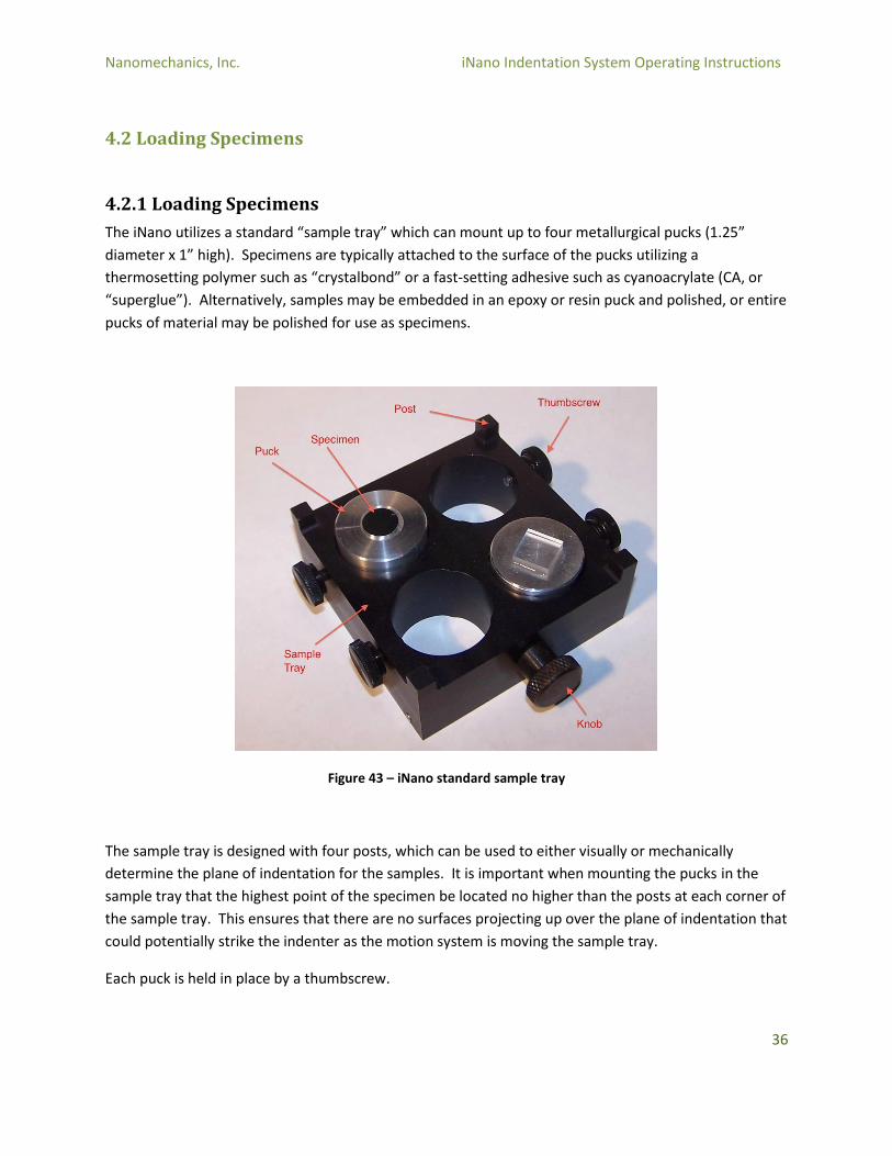
The iNano utilizes a standard “sample tray” which can mount up to four metallurgical pucks (1.25”
diameter x 1” high). Specimens are typically attached to the surface of the pucks utilizing a
thermosetting polymer such as “crystalbond” or a fast-setting adhesive such as cyanoacrylate (CA, or
“superglue”). Alternatively, samples may be embedded in an epoxy or resin puck and polished, or entire
pucks of material may be polished for use as specimens.
Figure 43 – iNano standard sample tray
The sample tray is designed with four posts, which can be used to either visually or mechanically
determine the plane of indentation for the samples. It is important when mounting the pucks in the
sample tray that the highest point of the specimen be located no higher than the posts at each corner of
the sample tray. This ensures that there are no surfaces projecting up over the plane of indentation that
could potentially strike the indenter as the motion system is moving the sample tray.
Each puck is held in place by a thumbscrew.
Nanomechanics, Inc. iNano Indentation System Operating Instructions
37
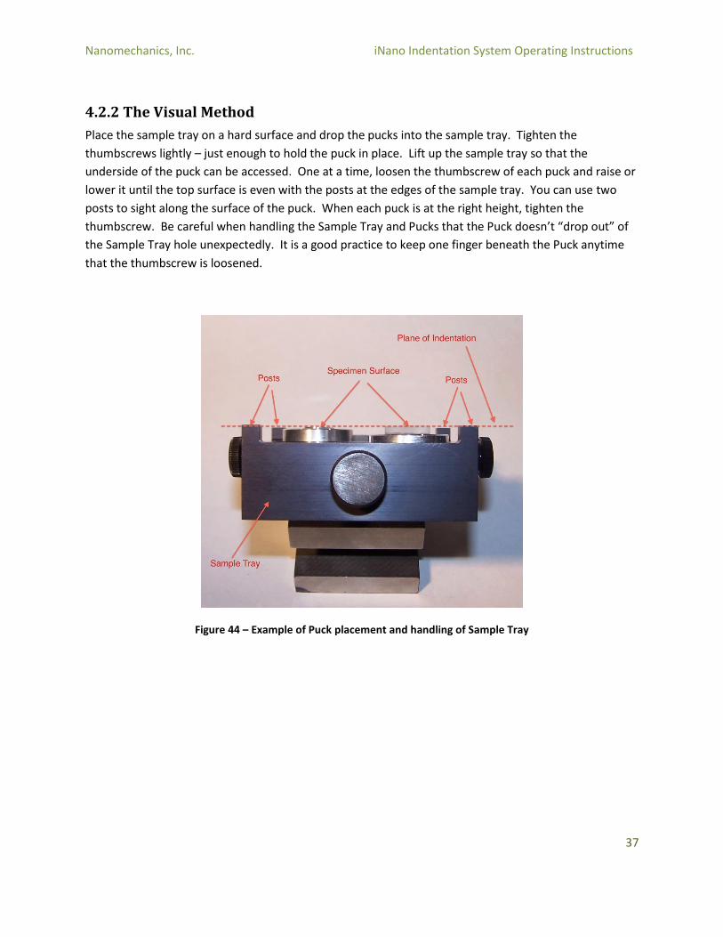
4.2.2 The Visual Method
Place the sample tray on a hard surface and drop the pucks into the sample tray. Tighten the
thumbscrews lightly – just enough to hold the puck in place. Lift up the sample tray so that the
underside of the puck can be accessed. One at a time, loosen the thumbscrew of each puck and raise or
lower it until the top surface is even with the posts at the edges of the sample tray. You can use two
posts to sight along the surface of the puck. When each puck is at the right height, tighten the
thumbscrew. Be careful when handling the Sample Tray and Pucks that the Puck doesn’t “drop out” of
the Sample Tray hole unexpectedly. It is a good practice to keep one finger beneath the Puck anytime
that the thumbscrew is loosened.
Figure 44 – Example of Puck placement and handling of Sample Tray
Nanomechanics, Inc. iNano Indentation System Operating Instructions
38
4.2.3 The Mechanical Method
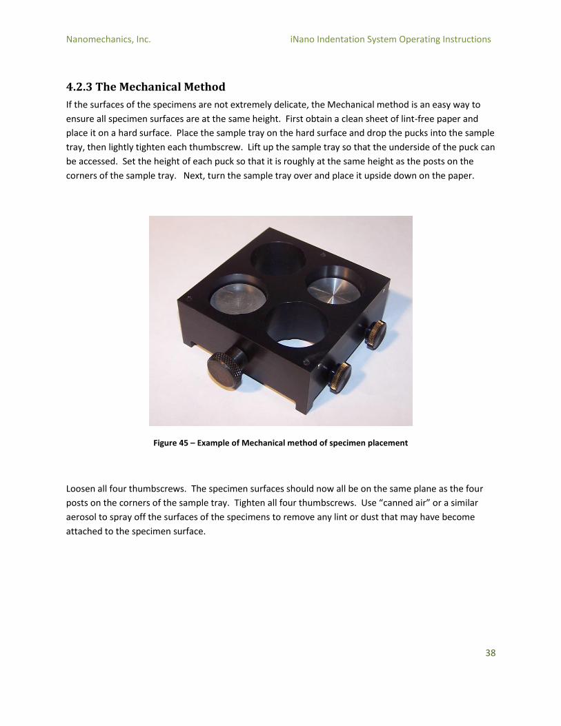
If the surfaces of the specimens are not extremely delicate, the Mechanical method is an easy way to
ensure all specimen surfaces are at the same height. First obtain a clean sheet of lint-free paper and
place it on a hard surface. Place the sample tray on the hard surface and drop the pucks into the sample
tray, then lightly tighten each thumbscrew. Lift up the sample tray so that the underside of the puck can
be accessed. Set the height of each puck so that it is roughly at the same height as the posts on the
corners of the sample tray. Next, turn the sample tray over and place it upside down on the paper.
Figure 45 – Example of Mechanical method of specimen placement
Loosen all four thumbscrews. The specimen surfaces should now all be on the same plane as the four
posts on the corners of the sample tray. Tighten all four thumbscrews. Use “canned air” or a similar
aerosol to spray off the surfaces of the specimens to remove any lint or dust that may have become
attached to the specimen surface.
Nanomechanics, Inc. iNano Indentation System Operating Instructions
39
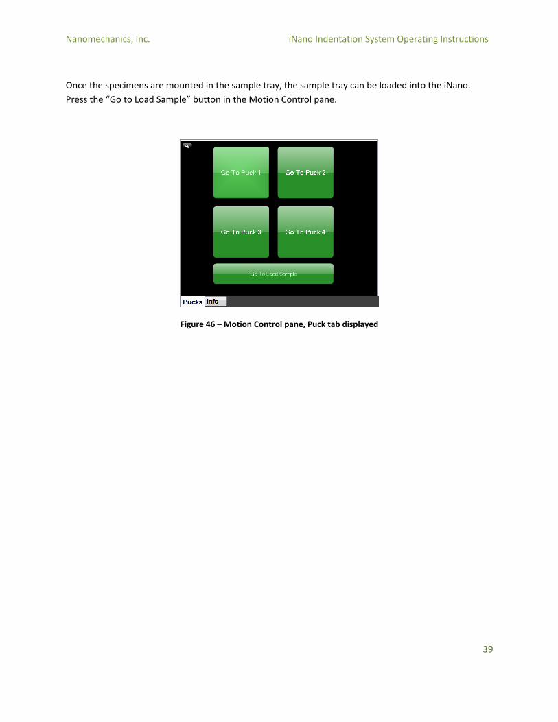
Once the specimens are mounted in the sample tray, the sample tray can be loaded into the iNano.
Press the “Go to Load Sample” button in the Motion Control pane.
Figure 46 – Motion Control pane, Puck tab displayed
Nanomechanics, Inc. iNano Indentation System Operating Instructions
40
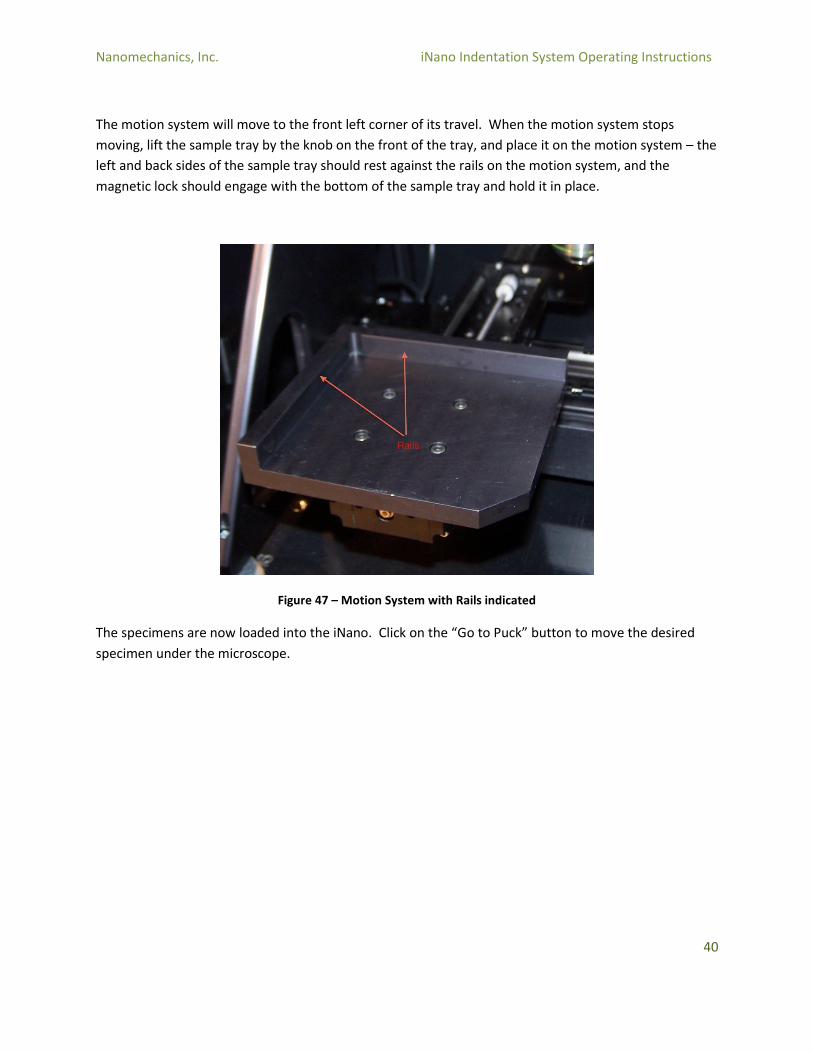
The motion system will move to the front left corner of its travel. When the motion system stops
moving, lift the sample tray by the knob on the front of the tray, and place it on the motion system – the
left and back sides of the sample tray should rest against the rails on the motion system, and the
magnetic lock should engage with the bottom of the sample tray and hold it in place.
Figure 47 – Motion System with Rails indicated
The specimens are now loaded into the iNano. Click on the “Go to Puck” button to move the desired
specimen under the microscope.

Nanomechanics, Inc. iNano Indentation System Operating Instructions
41
4.3 Video Source Calibration
Video Source Calibration
When indentation tests are performed, the user selects target locations using the microscope and
defines the tests to be performed at those locations. When the Run button is pressed, the system will
translate the samples from under the microscope to under the indenter. The distance that the system
will move in this translation is calibrated by the Video Source Calibration.
The principle of this calibration is that the user selects a target location on a sample in which large
indentations can be made. The iNano is provided with an aluminum calibration standard for this
purpose. Once the target location is selected, the system performs a set of five indentations, with the
center indentation located at the user’s target location.
When the sample is translated back under the microscope, the indentations should appear in the field of
view of the video screen, with the center indentation located under the red crosshairs. If the center
indentation is not located at the crosshair, the user manually moves the iNano stages so that the center
indent is under the crosshair. This correction is recorded by the software.
If the Video Source is very far out of calibration (as may occur after a tip change or when the actuator
has been removed from the system), the indentation might not be located in the field of view, in which
case the user must find the indentations. It is a good practice to select an area of the aluminum
calibration standard that is free of previous tests so that the wrong indentations are not selected. It is
also a good practice to place the indentations near a surface scratch or dust particle, which will serve as
a visual “home” point as the user searches for the indentations. Finally, the user can also note the X and
Y position of the target location on the meters pane so that the target position is not “lost” during a
search of the sample surface.
As a precursor to performing the video source calibration, the user must ensure that the Field of View is
properly calibrated. The Field of View calibration ensures that the distances displayed in the video pane
are accurate (that is, that the cursor position measures the distances displayed in the video pane
accurately). This calibration is performed by selecting a “feature” in the video image, using the motion
system to move that feature a known distance within the video image, and then reselecting the feature.
Nanomechanics, Inc. iNano Indentation System Operating Instructions
42
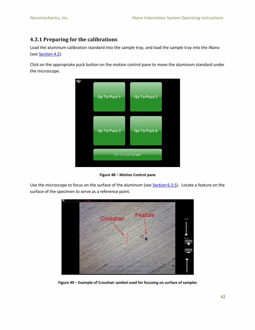
4.3.1 Preparing for the calibrations
Load the aluminum calibration standard into the sample tray, and load the sample tray into the iNano
(see Section 4.2).
Click on the appropriate puck button on the motion control pane to move the aluminum standard under
the microscope.
Figure 48 – Motion Control pane
Use the microscope to focus on the surface of the aluminum (see Section 6.3.5). Locate a feature on the
surface of the specimen to serve as a reference point.
Figure 49 – Example of Crosshair symbol used for focusing on surface of samples
Nanomechanics, Inc. iNano Indentation System Operating Instructions
43
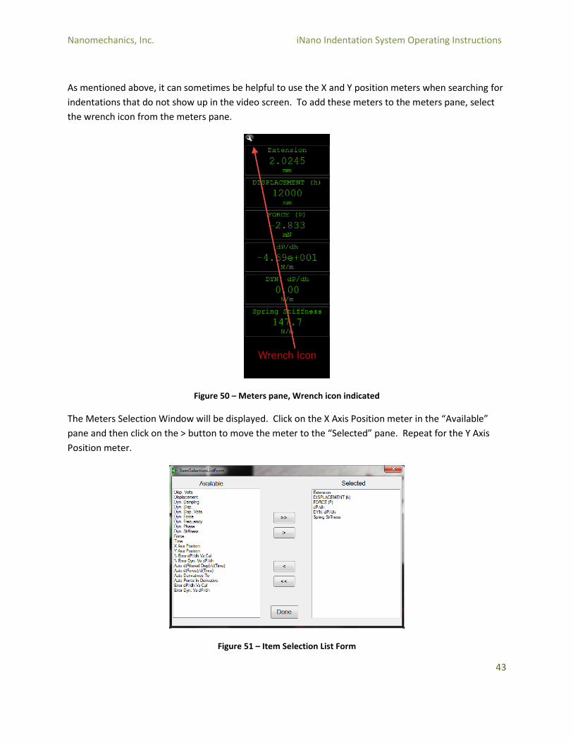
As mentioned above, it can sometimes be helpful to use the X and Y position meters when searching for
indentations that do not show up in the video screen. To add these meters to the meters pane, select
the wrench icon from the meters pane.
Figure 50 – Meters pane, Wrench icon indicated
The Meters Selection Window will be displayed. Click on the X Axis Position meter in the “Available”
pane and then click on the > button to move the meter to the “Selected” pane. Repeat for the Y Axis
Position meter.
Figure 51 – Item Selection List Form
Nanomechanics, Inc. iNano Indentation System Operating Instructions
44
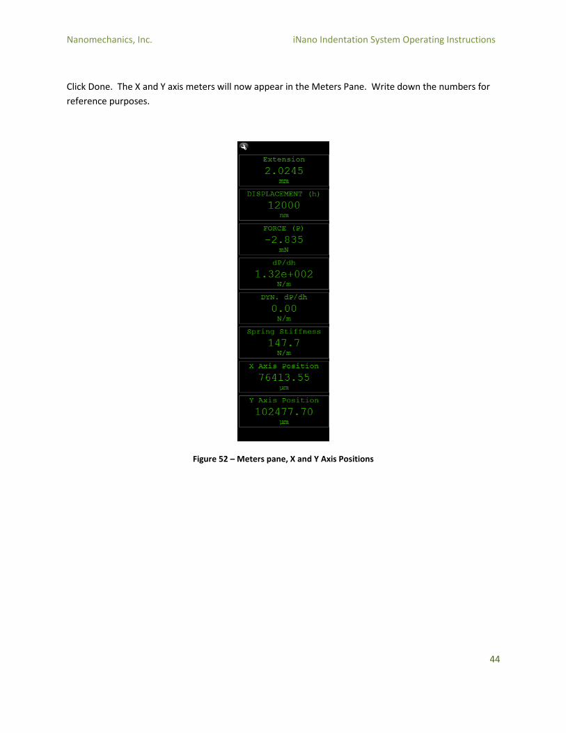
Click Done. The X and Y axis meters will now appear in the Meters Pane. Write down the numbers for
reference purposes.
Figure 52 – Meters pane, X and Y Axis Positions
Nanomechanics, Inc. iNano Indentation System Operating Instructions
45
4.3.2 Field of View Calibration
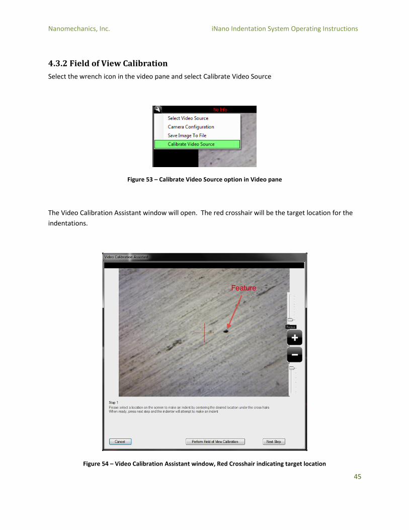
Select the wrench icon in the video pane and select Calibrate Video Source
Figure 53 – Calibrate Video Source option in Video pane
The Video Calibration Assistant window will open. The red crosshair will be the target location for the
indentations.
Figure 54 – Video Calibration Assistant window, Red Crosshair indicating target location
Nanomechanics, Inc. iNano Indentation System Operating Instructions
46
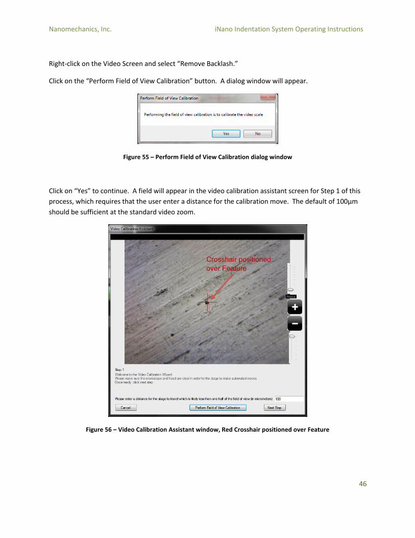
Right-click on the Video Screen and select “Remove Backlash.”
Click on the “Perform Field of View Calibration” button. A dialog window will appear.
Figure 55 – Perform Field of View Calibration dialog window
Click on “Yes” to continue. A field will appear in the video calibration assistant screen for Step 1 of this
process, which requires that the user enter a distance for the calibration move. The default of 100µm
should be sufficient at the standard video zoom.
Figure 56 – Video Calibration Assistant window, Red Crosshair positioned over Feature
Nanomechanics, Inc. iNano Indentation System Operating Instructions
47
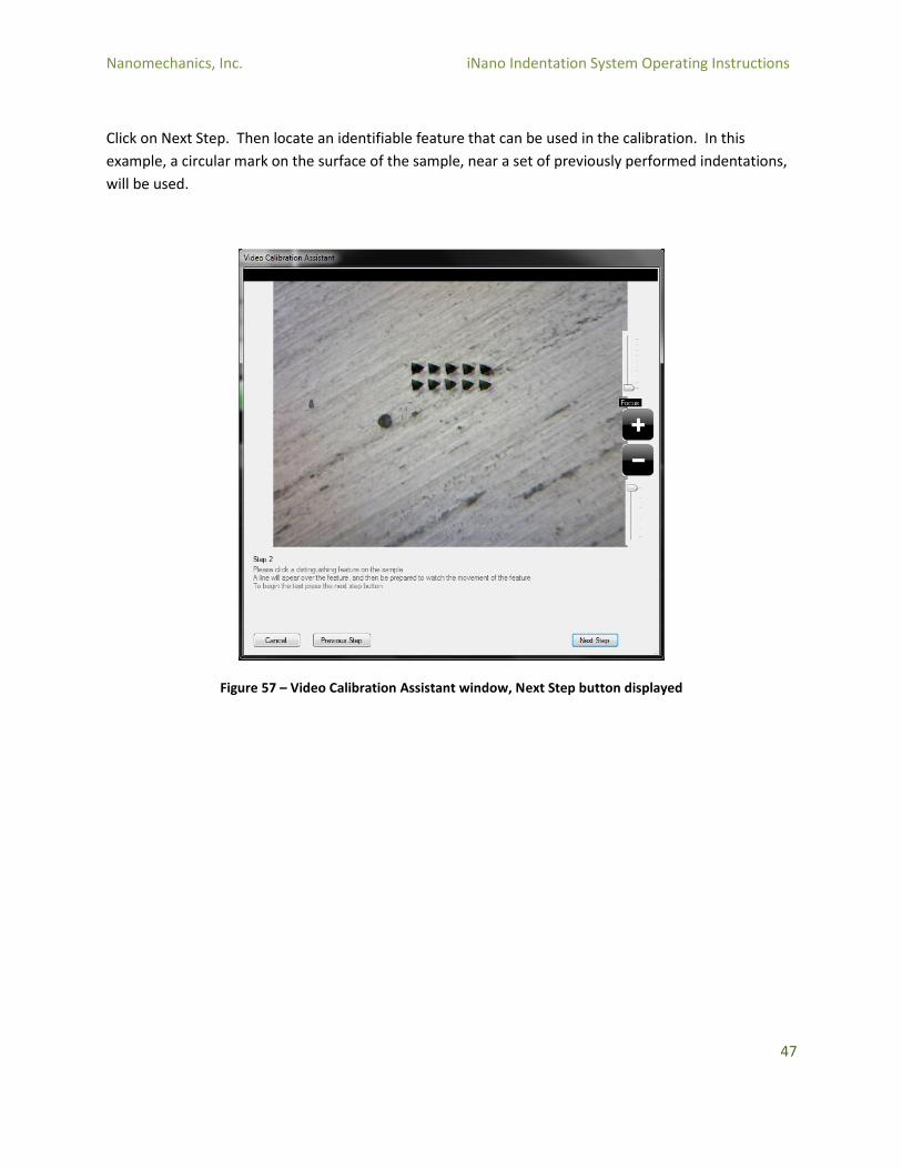
Click on Next Step. Then locate an identifiable feature that can be used in the calibration. In this
example, a circular mark on the surface of the sample, near a set of previously performed indentations,
will be used.
Figure 57 – Video Calibration Assistant window, Next Step button displayed
Nanomechanics, Inc. iNano Indentation System Operating Instructions
48
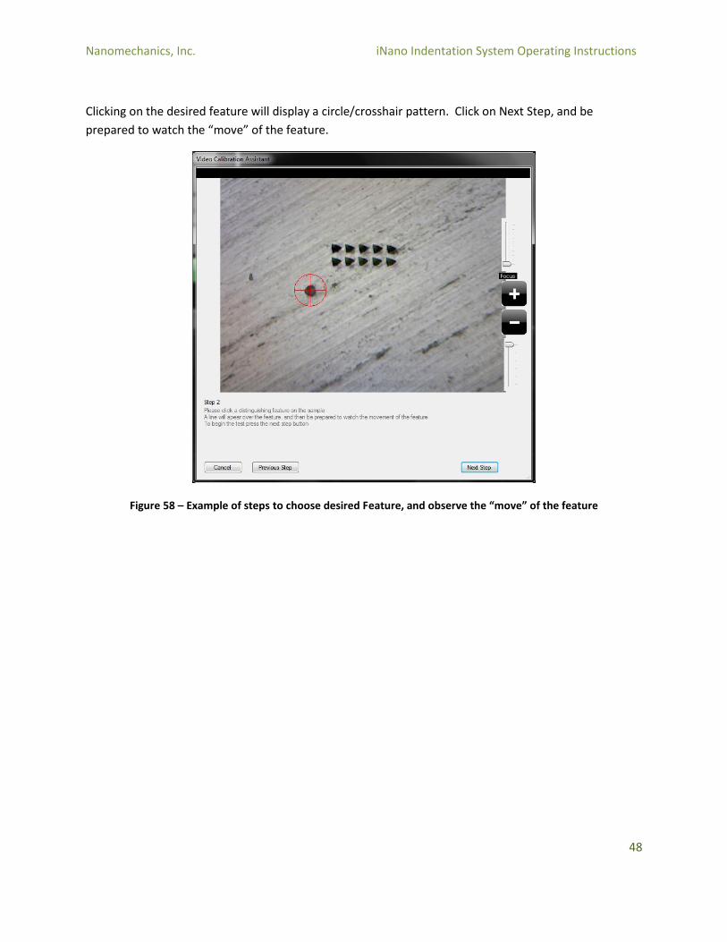
Clicking on the desired feature will display a circle/crosshair pattern. Click on Next Step, and be
prepared to watch the “move” of the feature.
Figure 58 – Example of steps to choose desired Feature, and observe the “move” of the feature
Nanomechanics, Inc. iNano Indentation System Operating Instructions
49
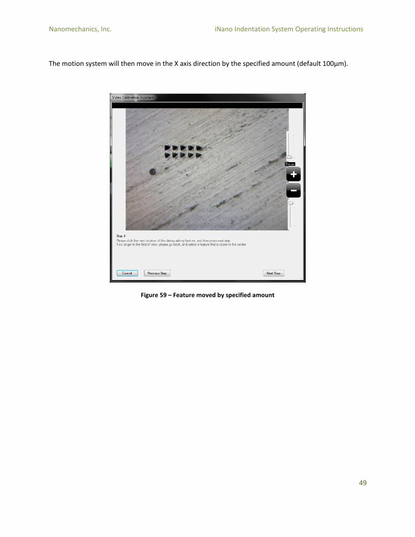
The motion system will then move in the X axis direction by the specified amount (default 100µm).
Figure 59 – Feature moved by specified amount
Nanomechanics, Inc. iNano Indentation System Operating Instructions
50
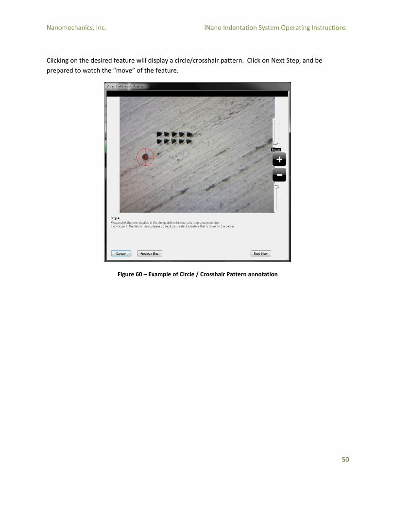
Clicking on the desired feature will display a circle/crosshair pattern. Click on Next Step, and be
prepared to watch the “move” of the feature.
Figure 60 – Example of Circle / Crosshair Pattern annotation

Nanomechanics, Inc. iNano Indentation System Operating Instructions
51
The motion system will then move in the Y axis direction by the specified amount (default 100µm).
Figure 61 – Example of Motion System movement in Y Axis direction
Nanomechanics, Inc. iNano Indentation System Operating Instructions
52
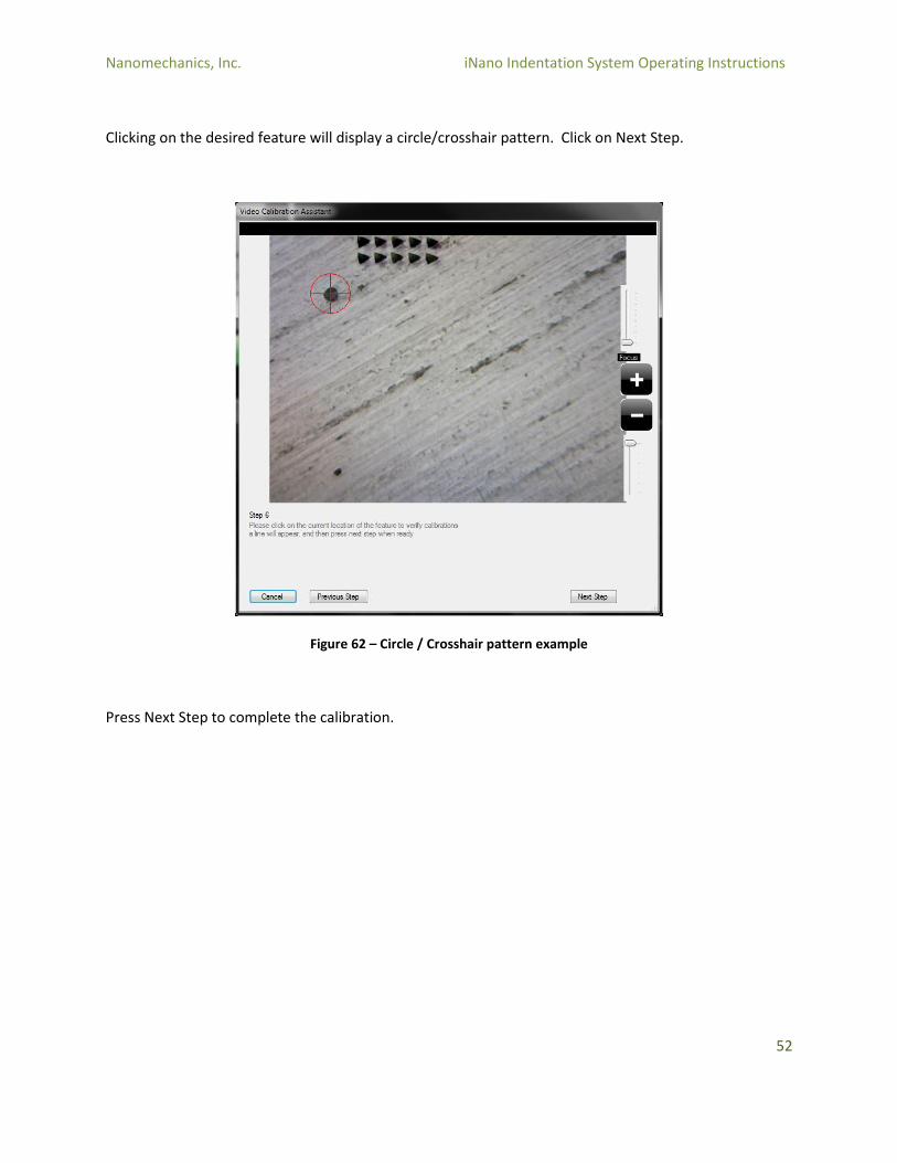
Clicking on the desired feature will display a circle/crosshair pattern. Click on Next Step.
Figure 62 – Circle / Crosshair pattern example
Press Next Step to complete the calibration.
Nanomechanics, Inc. iNano Indentation System Operating Instructions
53
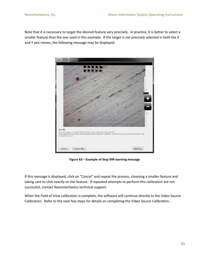
Note that it is necessary to target the desired feature very precisely. In practice, it is better to select a
smaller feature than the one used in this example. If the target is not precisely selected in both the X
and Y axis moves, the following message may be displayed:
Figure 63 – Example of Step 999 warning message
If this message is displayed, click on “Cancel” and repeat the process, choosing a smaller feature and
taking care to click exactly on the feature. If repeated attempts to perform this calibration are not
successful, contact Nanomechanics technical support.
When the Field of View calibration is complete, the software will continue directly to the Video Source
Calibration. Refer to the next few steps for details on completing the Video Source Calibration.
Nanomechanics, Inc. iNano Indentation System Operating Instructions
54
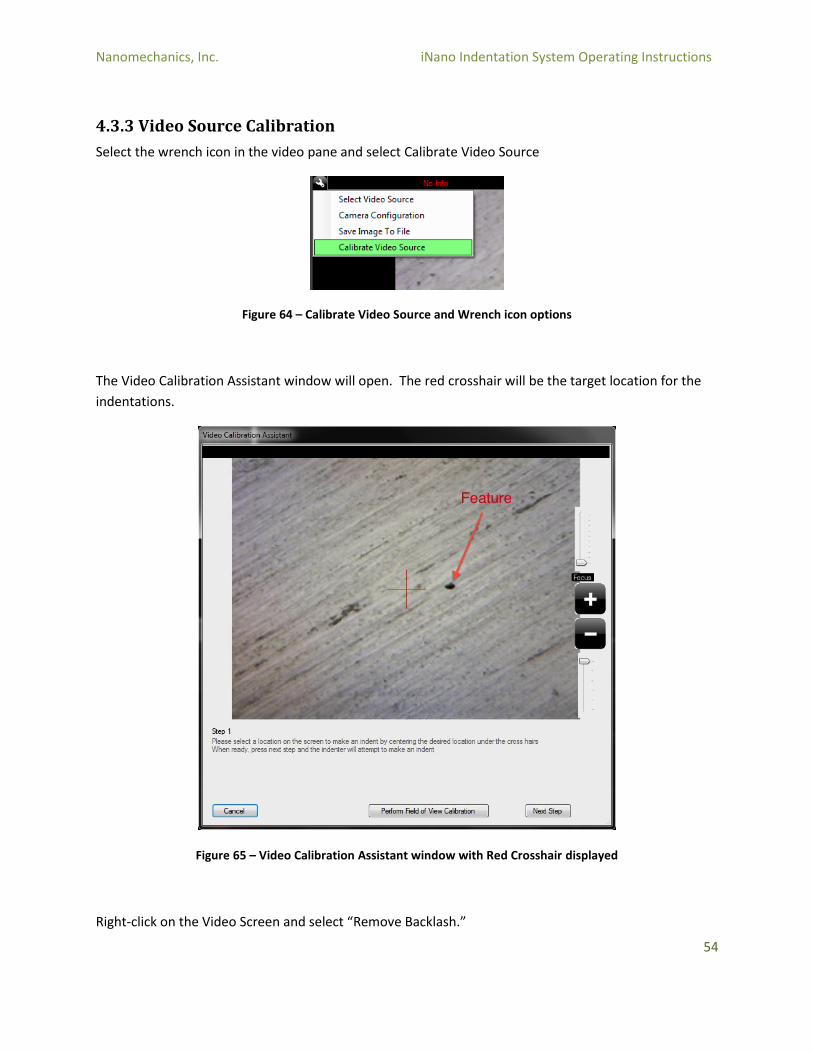
4.3.3 Video Source Calibration
Select the wrench icon in the video pane and select Calibrate Video Source
Figure 64 – Calibrate Video Source and Wrench icon options
The Video Calibration Assistant window will open. The red crosshair will be the target location for the
indentations.
Figure 65 – Video Calibration Assistant window with Red Crosshair displayed
Right-click on the Video Screen and select “Remove Backlash.”
Nanomechanics, Inc. iNano Indentation System Operating Instructions
55
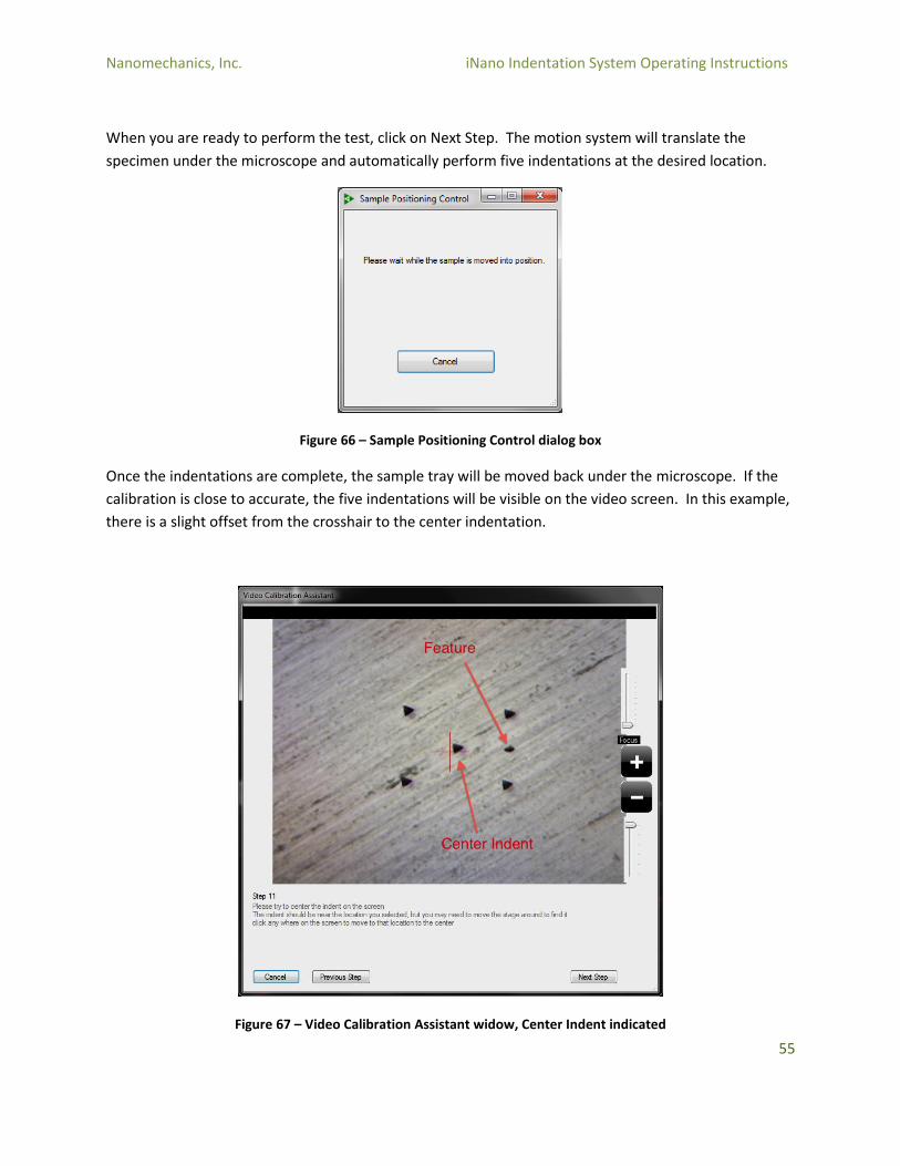
When you are ready to perform the test, click on Next Step. The motion system will translate the
specimen under the microscope and automatically perform five indentations at the desired location.
Figure 66 – Sample Positioning Control dialog box
Once the indentations are complete, the sample tray will be moved back under the microscope. If the
calibration is close to accurate, the five indentations will be visible on the video screen. In this example,
there is a slight offset from the crosshair to the center indentation.
Figure 67 – Video Calibration Assistant widow, Center Indent indicated
Nanomechanics, Inc. iNano Indentation System Operating Instructions
56
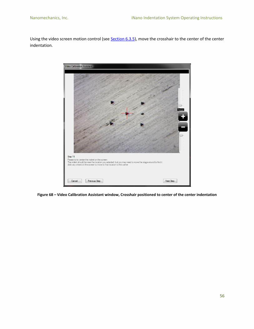
Using the video screen motion control (see Section 6.3.5), move the crosshair to the center of the center
indentation.
Figure 68 – Video Calibration Assistant window, Crosshair positioned to center of the center indentation
Nanomechanics, Inc. iNano Indentation System Operating Instructions
57
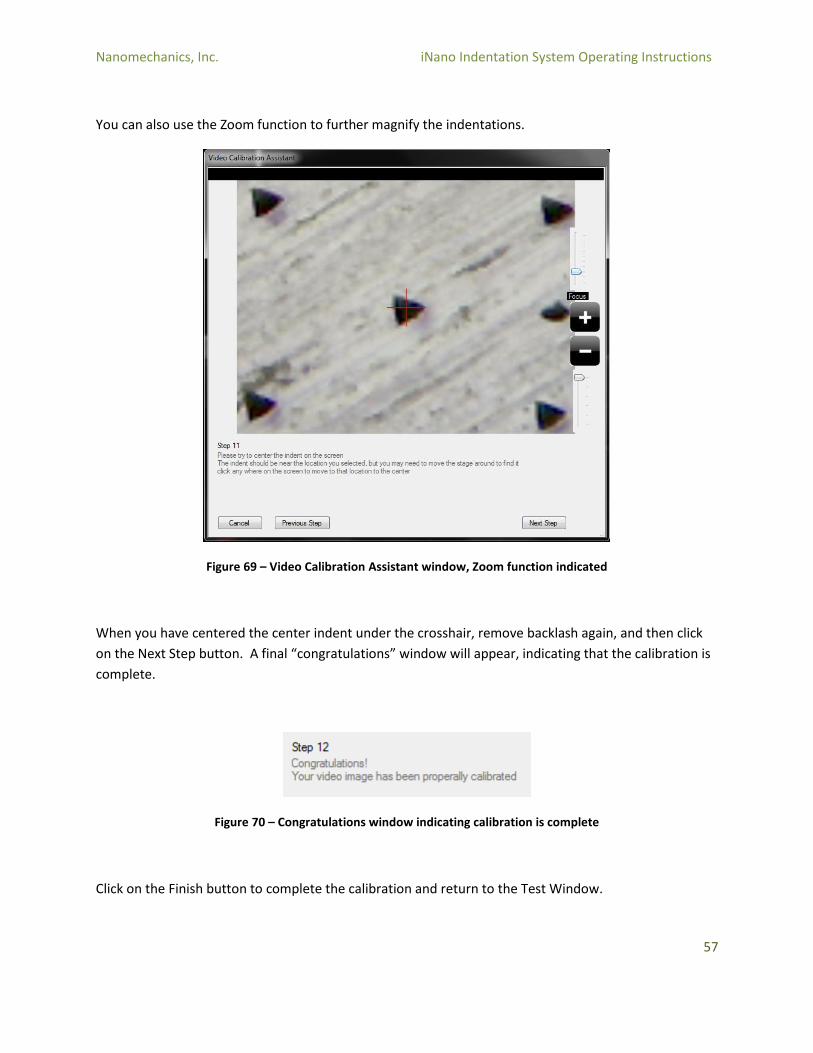
You can also use the Zoom function to further magnify the indentations.
Figure 69 – Video Calibration Assistant window, Zoom function indicated
When you have centered the center indent under the crosshair, remove backlash again, and then click
on the Next Step button. A final “congratulations” window will appear, indicating that the calibration is
complete.
Figure 70 – Congratulations window indicating calibration is complete
Click on the Finish button to complete the calibration and return to the Test Window.
Nanomechanics, Inc. iNano Indentation System Operating Instructions
58
4.4 Tip Change
Tip Change
Changing the indentation tip is a common procedure that is used when replacing a worn tip, or changing
to a different tip geometry. Care should be taken during this procedure, as it is possible to damage
either the tip, or the actuator.
Note that in this procedure, it is assumed that the tip is removed or installed without the use of an
optical magnifier or microscope. However, if a magnifier or high-depth-of-field microscope is available,
then the user of these tools can make it easier to remove or install the tip.
4.4.1 Removing the Tip
The first step is to perform an Operational Check so that a baseline dataset is available for comparison
with the post-tip-change Operational Check (see Section 4.1).
Use the Motion Control pane to “Go to Load Sample.” Open the iNano cabinet and remove the sample
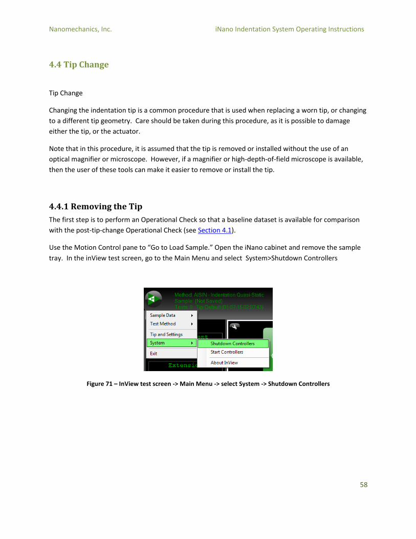
tray. In the inView test screen, go to the Main Menu and select System>Shutdown Controllers
Figure 71 – InView test screen -> Main Menu -> select System -> Shutdown Controllers

Nanomechanics, Inc. iNano Indentation System Operating Instructions
59
Physically turn the controller off by reaching through the access hole on the right rear corner of the
iNano cabinet and turning the power switch off.
Figure 72 – Access Hole on Controller Cabinet to turn the Power Switch off
Nanomechanics, Inc. iNano Indentation System Operating Instructions
60
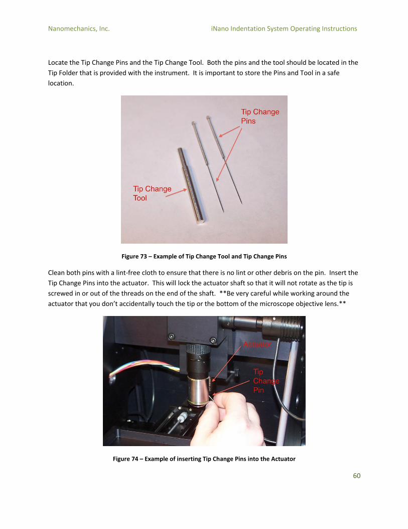
Locate the Tip Change Pins and the Tip Change Tool. Both the pins and the tool should be located in the
Tip Folder that is provided with the instrument. It is important to store the Pins and Tool in a safe
location.
Figure 73 – Example of Tip Change Tool and Tip Change Pins
Clean both pins with a lint-free cloth to ensure that there is no lint or other debris on the pin. Insert the
Tip Change Pins into the actuator. This will lock the actuator shaft so that it will not rotate as the tip is
screwed in or out of the threads on the end of the shaft. **Be very careful while working around the
actuator that you don’t accidentally touch the tip or the bottom of the microscope objective lens.**
Figure 74 – Example of inserting Tip Change Pins into the Actuator
Nanomechanics, Inc. iNano Indentation System Operating Instructions
61
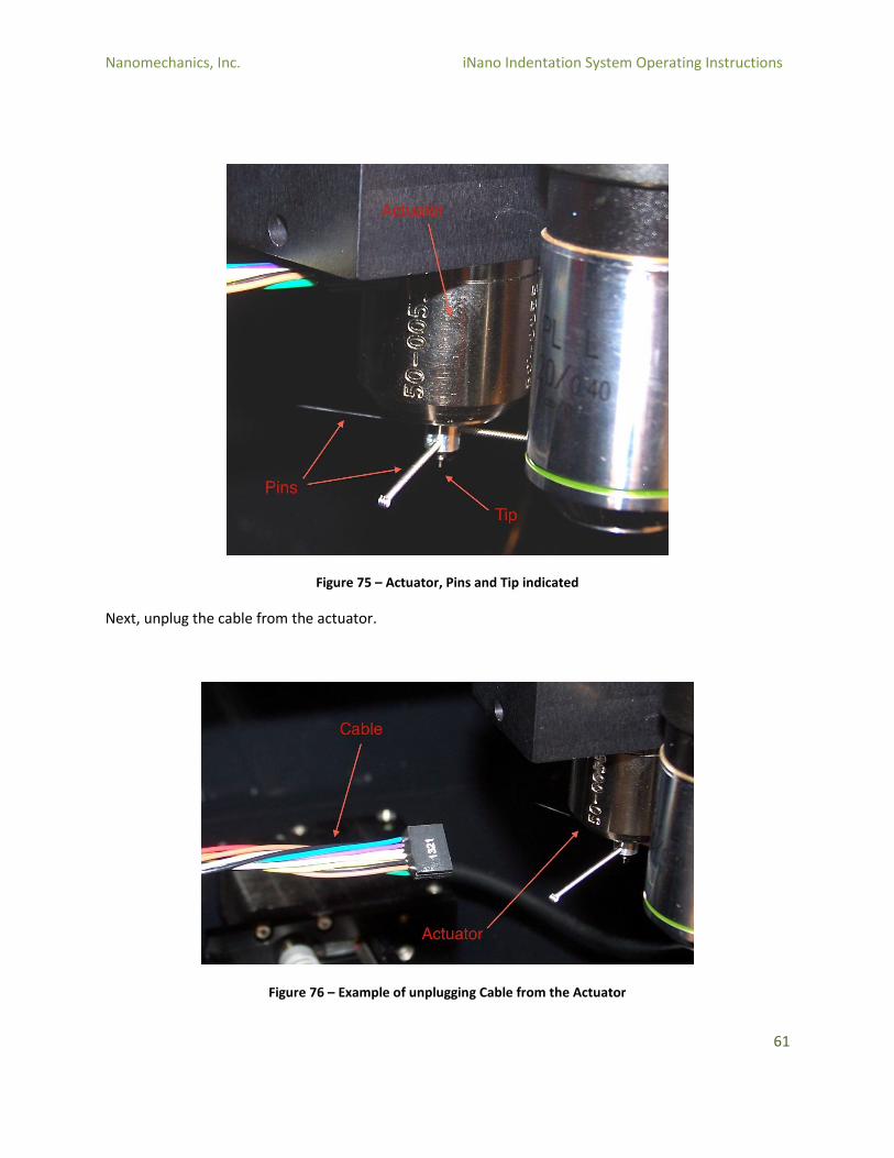
Figure 75 – Actuator, Pins and Tip indicated
Next, unplug the cable from the actuator.
Figure 76 – Example of unplugging Cable from the Actuator
Nanomechanics, Inc. iNano Indentation System Operating Instructions
62
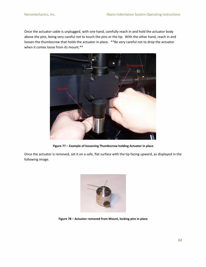
Once the actuator cable is unplugged, with one hand, carefully reach in and hold the actuator body
above the pins, being very careful not to touch the pins or the tip. With the other hand, reach in and
loosen the thumbscrew that holds the actuator in place. **Be very careful not to drop the actuator
when it comes loose from its mount.**
Figure 77 – Example of loosening Thumbscrew holding Actuator in place
Once the actuator is removed, set it on a safe, flat surface with the tip facing upward, as displayed in the
following image.
Figure 78 – Actuator removed from Mount, locking pins in place
Nanomechanics, Inc. iNano Indentation System Operating Instructions
63
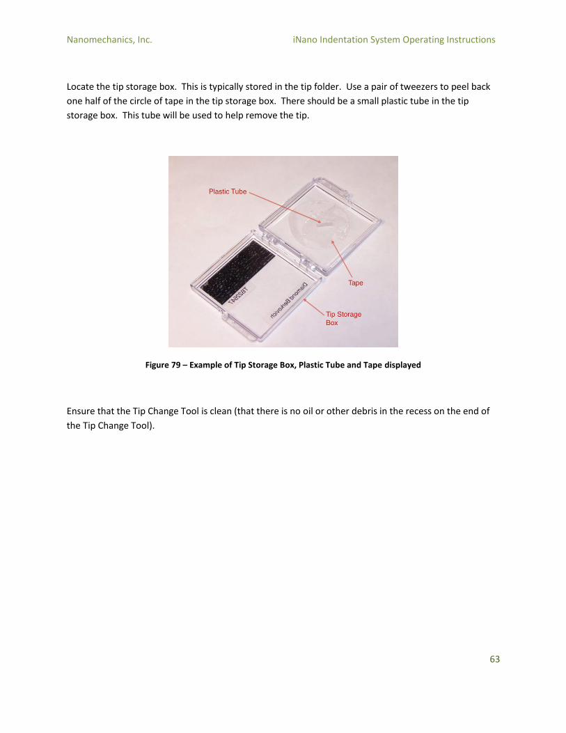
Locate the tip storage box. This is typically stored in the tip folder. Use a pair of tweezers to peel back
one half of the circle of tape in the tip storage box. There should be a small plastic tube in the tip
storage box. This tube will be used to help remove the tip.
Figure 79 – Example of Tip Storage Box, Plastic Tube and Tape displayed
Ensure that the Tip Change Tool is clean (that there is no oil or other debris in the recess on the end of
the Tip Change Tool).

Nanomechanics, Inc. iNano Indentation System Operating Instructions
64
Now that the tip storage box is prepared, use the tip change tool to carefully remove the tip from the
actuator. The tip uses standard threads, so it will be removed using a standard “left to loosen” motion.
Avoid placing lateral force on the indenter shaft while removing the tip. It is a good idea to perform this
operation over a sheet of white paper; in the event the tip is dropped it will be much easier to find it.
Figure 80 – Example of Tip Change Tool being used to remove the Tip from the Actuator
Nanomechanics, Inc. iNano Indentation System Operating Instructions
65
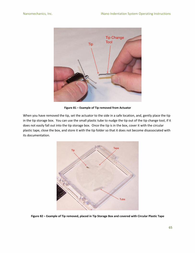
Figure 81 – Example of Tip removed from Actuator
When you have removed the tip, set the actuator to the side in a safe location, and, gently place the tip
in the tip storage box. You can use the small plastic tube to nudge the tip out of the tip change tool, if it
does not easily fall out into the tip storage box. Once the tip is in the box, cover it with the circular
plastic tape, close the box, and store it with the tip folder so that it does not become disassociated with
its documentation.
Figure 82 – Example of Tip removed, placed in Tip Storage Box and covered with Circular Plastic Tape
Nanomechanics, Inc. iNano Indentation System Operating Instructions
66
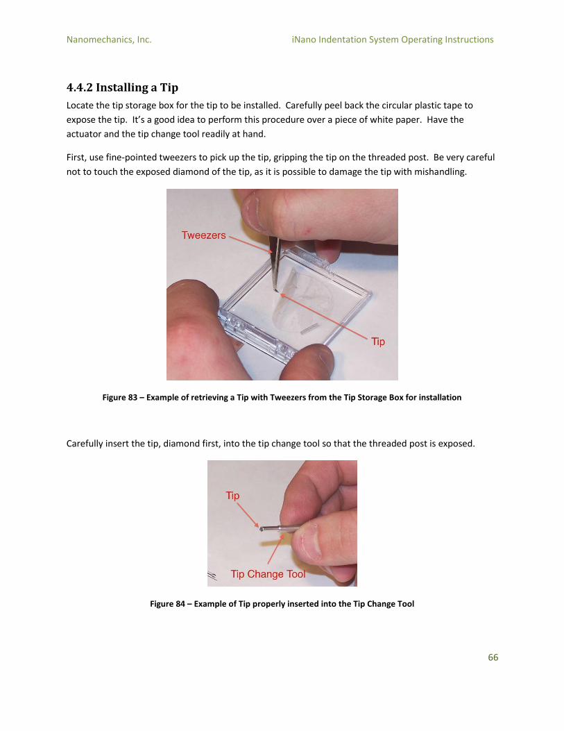
4.4.2 Installing a Tip
Locate the tip storage box for the tip to be installed. Carefully peel back the circular plastic tape to
expose the tip. It’s a good idea to perform this procedure over a piece of white paper. Have the
actuator and the tip change tool readily at hand.
First, use fine-pointed tweezers to pick up the tip, gripping the tip on the threaded post. Be very careful
not to touch the exposed diamond of the tip, as it is possible to damage the tip with mishandling.
Figure 83 – Example of retrieving a Tip with Tweezers from the Tip Storage Box for installation
Carefully insert the tip, diamond first, into the tip change tool so that the threaded post is exposed.
Figure 84 – Example of Tip properly inserted into the Tip Change Tool
Nanomechanics, Inc. iNano Indentation System Operating Instructions
67
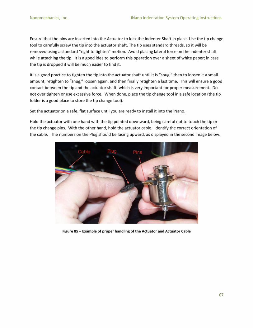
Ensure that the pins are inserted into the Actuator to lock the Indenter Shaft in place. Use the tip change
tool to carefully screw the tip into the actuator shaft. The tip uses standard threads, so it will be
removed using a standard “right to tighten” motion. Avoid placing lateral force on the indenter shaft
while attaching the tip. It is a good idea to perform this operation over a sheet of white paper; in case
the tip is dropped it will be much easier to find it.
It is a good practice to tighten the tip into the actuator shaft until it is “snug,” then to loosen it a small
amount, retighten to “snug,” loosen again, and then finally retighten a last time. This will ensure a good
contact between the tip and the actuator shaft, which is very important for proper measurement. Do
not over tighten or use excessive force. When done, place the tip change tool in a safe location (the tip
folder is a good place to store the tip change tool).
Set the actuator on a safe, flat surface until you are ready to install it into the iNano.
Hold the actuator with one hand with the tip pointed downward, being careful not to touch the tip or
the tip change pins. With the other hand, hold the actuator cable. Identify the correct orientation of
the cable. The numbers on the Plug should be facing upward, as displayed in the second image below.
Figure 85 – Example of proper handling of the Actuator and Actuator Cable
Nanomechanics, Inc. iNano Indentation System Operating Instructions
68
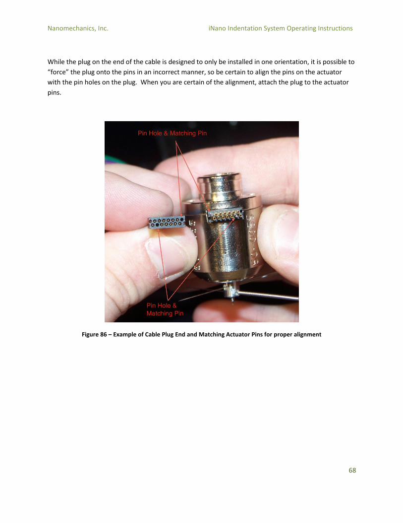
While the plug on the end of the cable is designed to only be installed in one orientation, it is possible to
“force” the plug onto the pins in an incorrect manner, so be certain to align the pins on the actuator
with the pin holes on the plug. When you are certain of the alignment, attach the plug to the actuator
pins.
Figure 86 – Example of Cable Plug End and Matching Actuator Pins for proper alignment
Nanomechanics, Inc. iNano Indentation System Operating Instructions
69
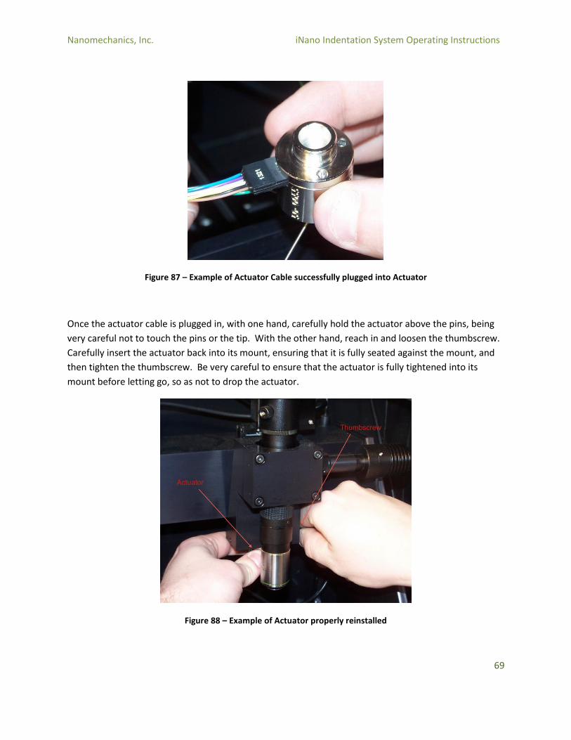
Figure 87 – Example of Actuator Cable successfully plugged into Actuator
Once the actuator cable is plugged in, with one hand, carefully hold the actuator above the pins, being
very careful not to touch the pins or the tip. With the other hand, reach in and loosen the thumbscrew.
Carefully insert the actuator back into its mount, ensuring that it is fully seated against the mount, and
then tighten the thumbscrew. Be very careful to ensure that the actuator is fully tightened into its
mount before letting go, so as not to drop the actuator.
Figure 88 – Example of Actuator properly reinstalled
Nanomechanics, Inc. iNano Indentation System Operating Instructions
70
When the actuator is installed, remove the tip change pins and place them in a safe location (the tip
folder is an ideal place to store the tip change pins).
Physically turn the controller on by reaching through the access hole on the right rear corner of the
iNano cabinet and turning the power switch on.
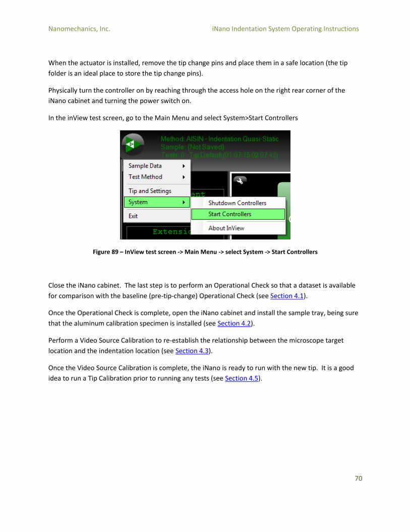
In the inView test screen, go to the Main Menu and select System>Start Controllers
Figure 89 – InView test screen -> Main Menu -> select System -> Start Controllers
Close the iNano cabinet. The last step is to perform an Operational Check so that a dataset is available
for comparison with the baseline (pre-tip-change) Operational Check (see Section 4.1).
Once the Operational Check is complete, open the iNano cabinet and install the sample tray, being sure
that the aluminum calibration specimen is installed (see Section 4.2).
Perform a Video Source Calibration to re-establish the relationship between the microscope target
location and the indentation location (see Section 4.3).
Once the Video Source Calibration is complete, the iNano is ready to run with the new tip. It is a good
idea to run a Tip Calibration prior to running any tests (see Section 4.5).

Nanomechanics, Inc. iNano Indentation System Operating Instructions
71
4.5 Advanced Tip Calibration
Advanced Tip Calibration
The conversion of the acquired data of load and displacement to the desired engineering properties of
modulus and hardness depends upon the “contact area” of the indentation. If the diamond tip was
perfect (and neglecting other factors such as sink-in and pile-up), the contact area could be determined
from just the geometry of the diamond tip and the contact depth. For all real diamond tips, however,
there is some degree of imperfection – whether in the face angles of the diamond or in rounding at the
tip. The smaller the indentation, the more this imperfection comes into play.
In order to compensate for these imperfections, the Advanced Tip Calibration procedure is used. In this
procedure, indentations are performed on a well-known material (fused silica). The results of these
indentations are used to calculate the relationship between the contact depth and the area.
A related problem is the load frame stiffness of the indentation system. The spring model for the
indentation system includes not only the stiffness of the specimen (measured), but the stiffness of the
load frame as well. This means that in a measured displacement, the largest component is the
penetration into the specimen surface, but a small component will come from the deflection of the load
frame. The larger the indentation load, the more the load frame stiffness comes into play.
The load frame stiffness is calibrated for the indentation system, but the same data that is used to
calculate the tip geometry correction can also be used to calculate the load frame stiffness correction.
Reference will be made to load frame stiffness in this procedure, although it is generally unnecessary to
recalculate the load frame stiffness correction.
The Advanced Tip Calibration procedure will be need to be performed when a new tip is to be used, or
when a tip has been worn by repeated use.
There are many potential parameters that can be changed in the Advanced Tip Calibration. This
procedure focuses on the most commonly used, and most effective technique. If further understanding
of the Advanced Tip Calibration or its parameters is desired, please contact Nanomechanics for
resources.
Finally, the Advanced Tip Calibration can be used for a variety of tip geometries, although the most
common is the Berkovich geometry. This procedure only addresses the Berkovich geometry. In this
procedure, a new tip is defined, as opposed to the recalibration of an existing tip.
The first step in performing the Advanced Tip Calibration is to run the experiments and generate the
data. Begin by opening the InView Test window.
Nanomechanics, Inc. iNano Indentation System Operating Instructions
72
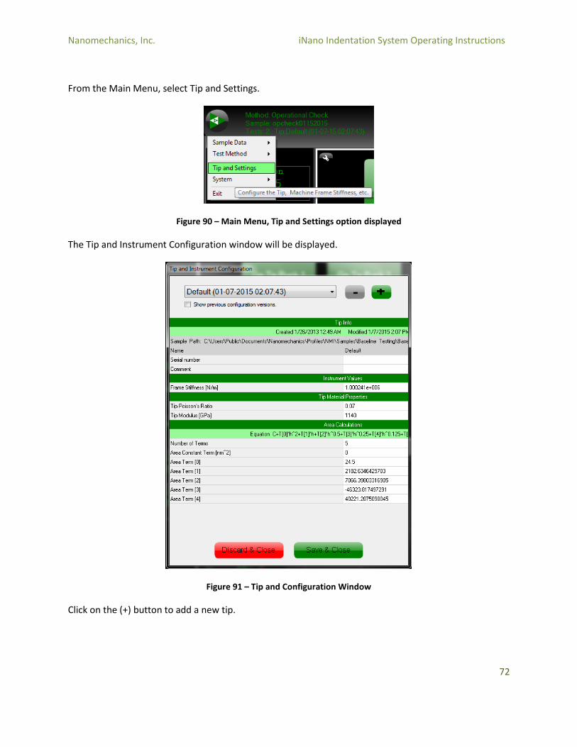
From the Main Menu, select Tip and Settings.
Figure 90 – Main Menu, Tip and Settings option displayed
The Tip and Instrument Configuration window will be displayed.
Figure 91 – Tip and Configuration Window
Click on the (+) button to add a new tip.
Nanomechanics, Inc. iNano Indentation System Operating Instructions
73
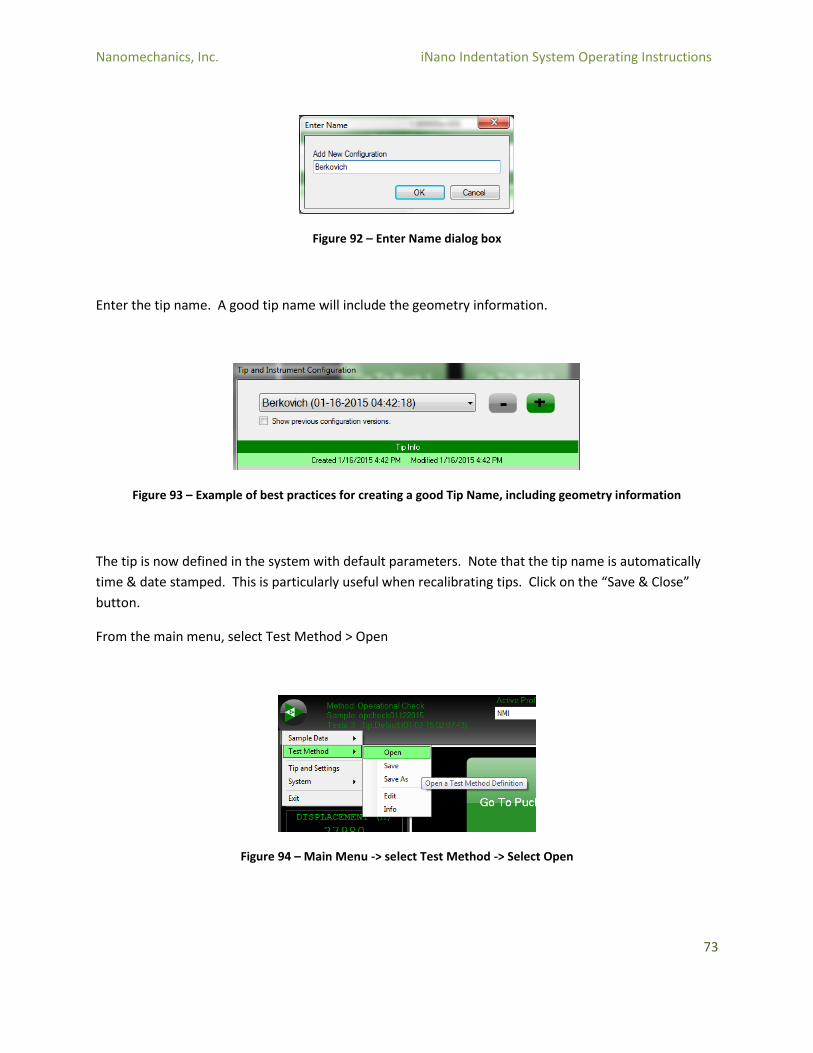
Figure 92 – Enter Name dialog box
Enter the tip name. A good tip name will include the geometry information.
Figure 93 – Example of best practices for creating a good Tip Name, including geometry information
The tip is now defined in the system with default parameters. Note that the tip name is automatically
time & date stamped. This is particularly useful when recalibrating tips. Click on the “Save & Close”
button.
From the main menu, select Test Method > Open
Figure 94 – Main Menu -> select Test Method -> Select Open
Nanomechanics, Inc. iNano Indentation System Operating Instructions
74
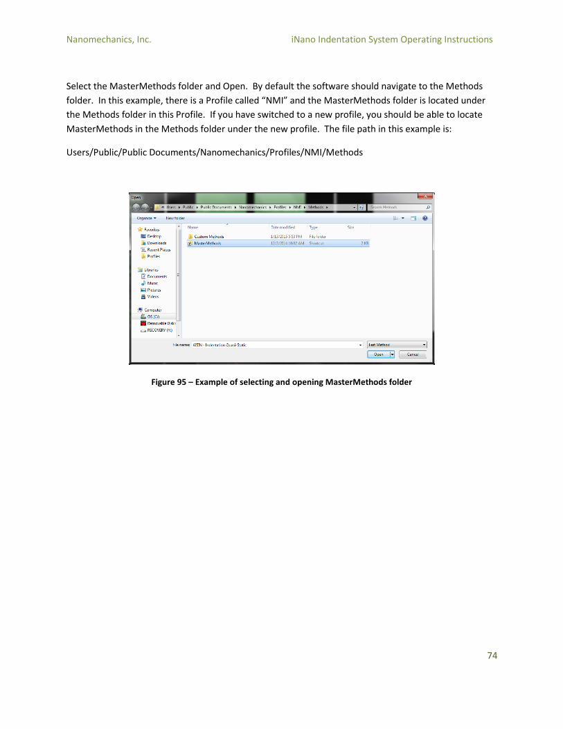
Select the MasterMethods folder and Open. By default the software should navigate to the Methods
folder. In this example, there is a Profile called “NMI” and the MasterMethods folder is located under
the Methods folder in this Profile. If you have switched to a new profile, you should be able to locate
MasterMethods in the Methods folder under the new profile. The file path in this example is:
Users/Public/Public Documents/Nanomechanics/Profiles/NMI/Methods
Figure 95 – Example of selecting and opening MasterMethods folder
Nanomechanics, Inc. iNano Indentation System Operating Instructions
75
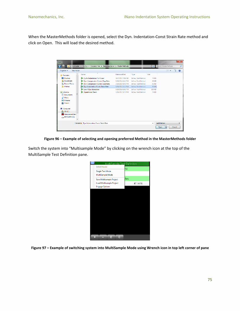
When the MasterMethods folder is opened, select the Dyn. Indentation-Const Strain Rate method and
click on Open. This will load the desired method.
Figure 96 – Example of selecting and opening preferred Method in the MasterMethods folder
Switch the system into “Multisample Mode” by clicking on the wrench icon at the top of the
MultiSample Test Definition pane.
Figure 97 – Example of switching system into MultiSample Mode using Wrench icon in top left corner of pane
Nanomechanics, Inc. iNano Indentation System Operating Instructions
76
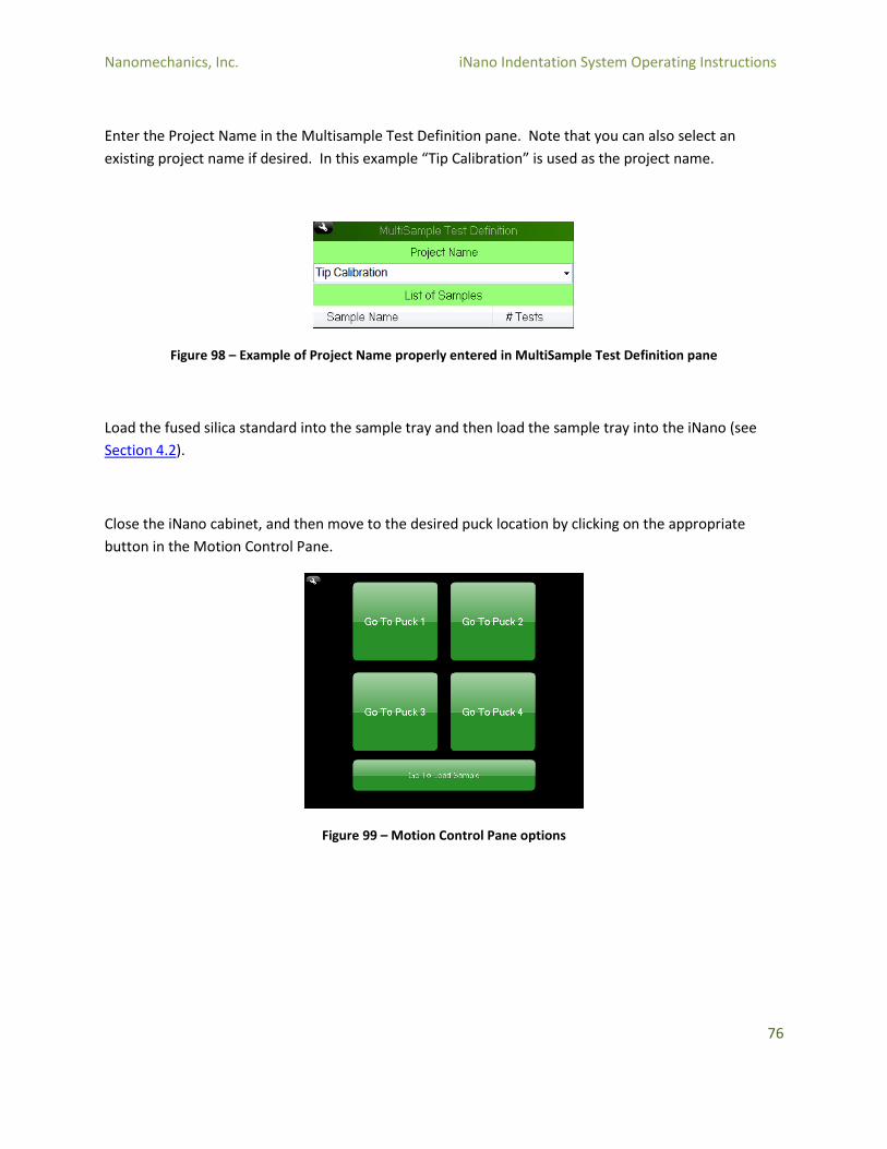
Enter the Project Name in the Multisample Test Definition pane. Note that you can also select an
existing project name if desired. In this example “Tip Calibration” is used as the project name.
Figure 98 – Example of Project Name properly entered in MultiSample Test Definition pane
Load the fused silica standard into the sample tray and then load the sample tray into the iNano (see
Section 4.2).
Close the iNano cabinet, and then move to the desired puck location by clicking on the appropriate
button in the Motion Control Pane.
Figure 99 – Motion Control Pane options

Nanomechanics, Inc. iNano Indentation System Operating Instructions
77
Focus on the surface of the fused silica standard (see Section 6.3.5) and locate a clear area of the surface
to place the indentation array.
Figure 100 – Example of locating a clear area of the surface for indentation array placement
In the Multisample Test Definition Pane above, click on the (+) button to add a new Sample. Enter the
sample name. In this example, “Fused Silica” is used.
Figure 101 – Example of new Sample Name entered into MultiSample Add Sample pane
Nanomechanics, Inc. iNano Indentation System Operating Instructions
78
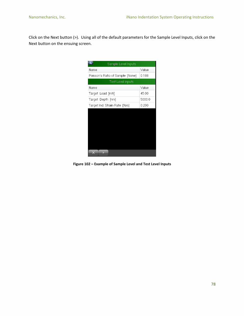
Click on the Next button (>). Using all of the default parameters for the Sample Level Inputs, click on the
Next button on the ensuing screen.
Figure 102 – Example of Sample Level and Test Level Inputs
Nanomechanics, Inc. iNano Indentation System Operating Instructions
79
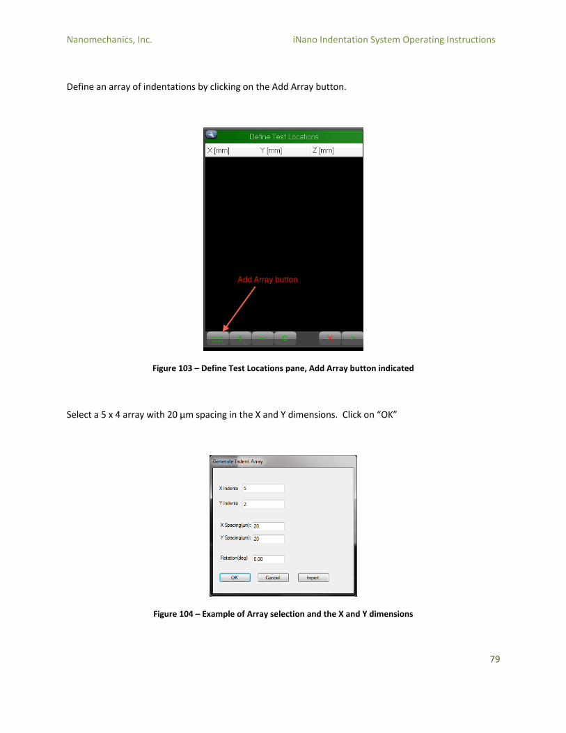
Define an array of indentations by clicking on the Add Array button.
Figure 103 – Define Test Locations pane, Add Array button indicated
Select a 5 x 4 array with 20 µm spacing in the X and Y dimensions. Click on “OK”
Figure 104 – Example of Array selection and the X and Y dimensions

Nanomechanics, Inc. iNano Indentation System Operating Instructions
80
Click on the Next button (>) in the Define Test Locations screen.
Figure 105 – Define Test Locations pane
The test is now ready to run. Click on the green Run button to start the test.
Figure 106 – Green Run Button
Once the tests are complete, go to the Review program by selecting the InView Review icon from the
bottom tool bar.
Figure 107 – InView Review program icon indicated in bottom tool bar
Nanomechanics, Inc. iNano Indentation System Operating Instructions
81
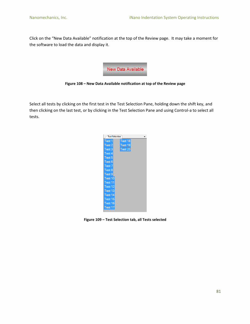
Click on the “New Data Available” notification at the top of the Review page. It may take a moment for
the software to load the data and display it.
Figure 108 – New Data Available notification at top of the Review page
Select all tests by clicking on the first test in the Test Selection Pane, holding down the shift key, and
then clicking on the last test, or by clicking in the Test Selection Pane and using Control-a to select all
tests.
Figure 109 – Test Selection tab, all Tests selected
Nanomechanics, Inc. iNano Indentation System Operating Instructions
82
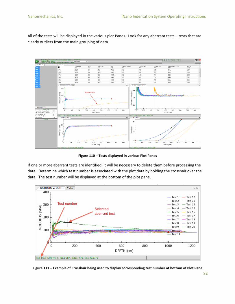
All of the tests will be displayed in the various plot Panes. Look for any aberrant tests – tests that are
clearly outliers from the main grouping of data.
Figure 110 – Tests displayed in various Plot Panes
If one or more aberrant tests are identified, it will be necessary to delete them before processing the
data. Determine which test number is associated with the plot data by holding the crosshair over the
data. The test number will be displayed at the bottom of the plot pane.
Figure 111 – Example of Crosshair being used to display corresponding test number at bottom of Plot Pane
Nanomechanics, Inc. iNano Indentation System Operating Instructions
83
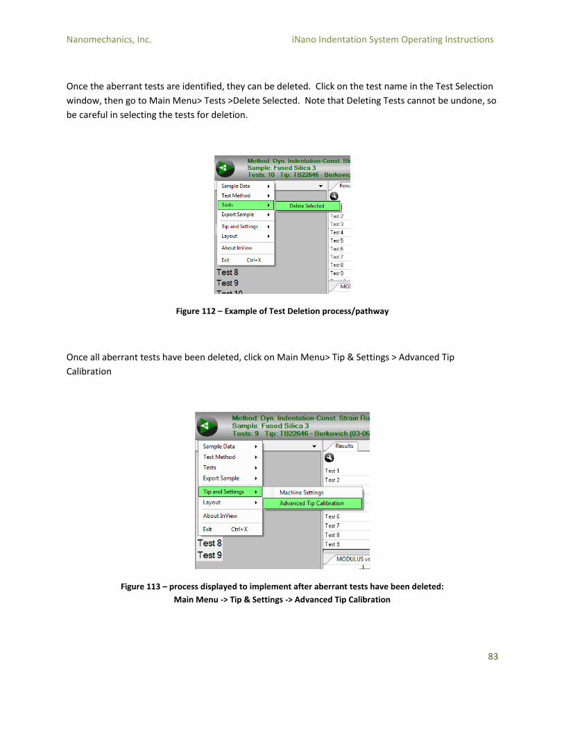
Once the aberrant tests are identified, they can be deleted. Click on the test name in the Test Selection
window, then go to Main Menu> Tests >Delete Selected. Note that Deleting Tests cannot be undone, so
be careful in selecting the tests for deletion.
Figure 112 – Example of Test Deletion process/pathway
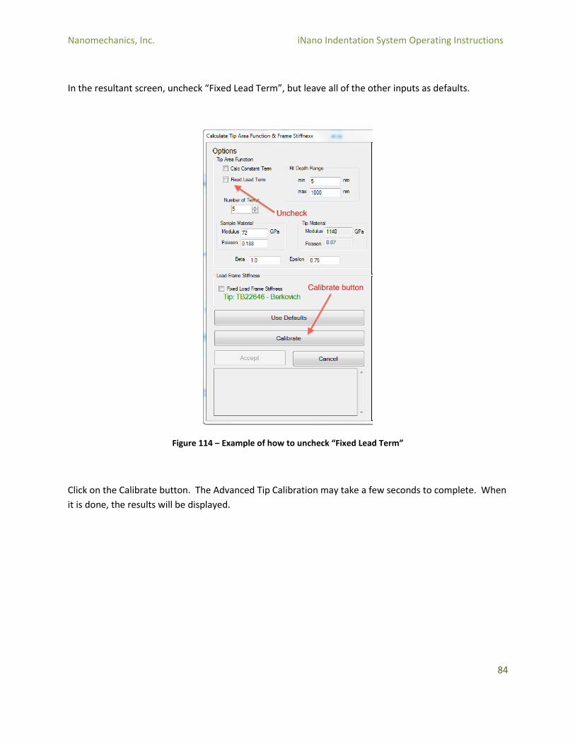
Once all aberrant tests have been deleted, click on Main Menu> Tip & Settings > Advanced Tip
Calibration
Figure 113 – process displayed to implement after aberrant tests have been deleted:
Main Menu -> Tip & Settings -> Advanced Tip Calibration
Nanomechanics, Inc. iNano Indentation System Operating Instructions
84
In the resultant screen, uncheck “Fixed Lead Term”, but leave all of the other inputs as defaults.
Figure 114 – Example of how to uncheck “Fixed Lead Term”
Click on the Calibrate button. The Advanced Tip Calibration may take a few seconds to complete. When
it is done, the results will be displayed.
Nanomechanics, Inc. iNano Indentation System Operating Instructions
85
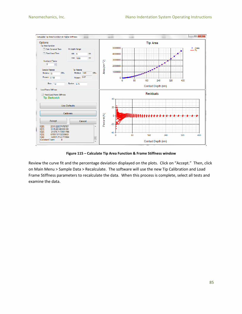
Figure 115 – Calculate Tip Area Function & Frame Stiffness window
Review the curve fit and the percentage deviation displayed on the plots. Click on “Accept.” Then, click
on Main Menu > Sample Data > Recalculate. The software will use the new Tip Calibration and Load
Frame Stiffness parameters to recalculate the data. When this process is complete, select all tests and
examine the data.
Nanomechanics, Inc. iNano Indentation System Operating Instructions
86
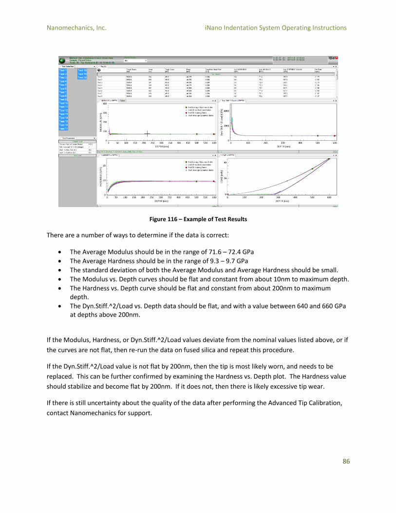
Figure 116 – Example of Test Results
There are a number of ways to determine if the data is correct:
The Average Modulus should be in the range of 71.6 – 72.4 GPa
The Average Hardness should be in the range of 9.3 – 9.7 GPa
The standard deviation of both the Average Modulus and Average Hardness should be small.
The Modulus vs. Depth curves should be flat and constant from about 10nm to maximum depth.
The Hardness vs. Depth curve should be flat and constant from about 200nm to maximum depth.
The Dyn.Stiff.^2/Load vs. Depth data should be flat, and with a value between 640 and 660 GPa at depths above 200nm.
If the Modulus, Hardness, or Dyn.Stiff.^2/Load values deviate from the nominal values listed above, or if
the curves are not flat, then re-run the data on fused silica and repeat this procedure.
If the Dyn.Stiff.^2/Load value is not flat by 200nm, then the tip is most likely worn, and needs to be
replaced. This can be further confirmed by examining the Hardness vs. Depth plot. The Hardness value
should stabilize and become flat by 200nm. If it does not, then there is likely excessive tip wear.
If there is still uncertainty about the quality of the data after performing the Advanced Tip Calibration,
contact Nanomechanics for support.

Nanomechanics, Inc. iNano Indentation System Operating Instructions
87
5.0 Hardware Reference
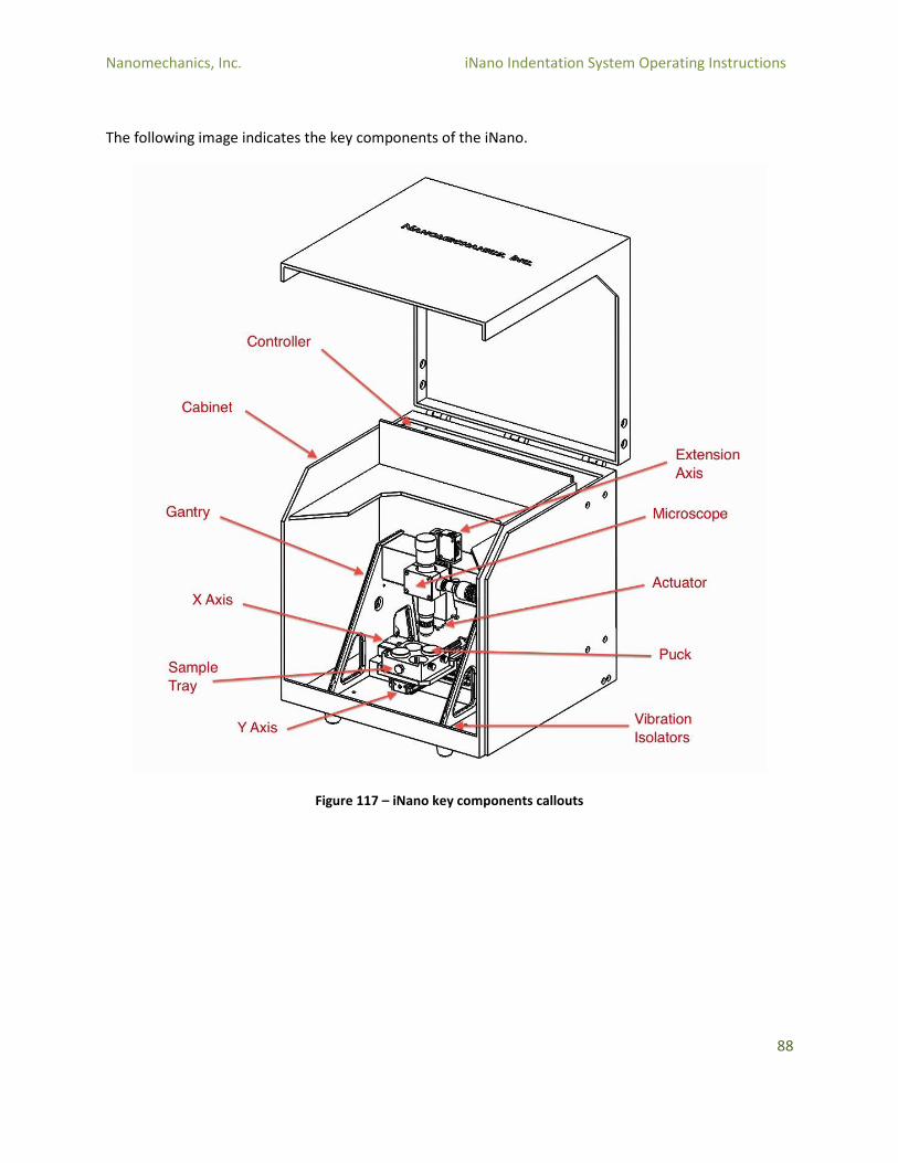
5.1 Overview of the System The iNano consists of a number of subsystems:
CPU: The computer that operates the iNano, including the keyboard and mouse.
Isolation Cabinet: The enclosure that contains the iNano gantry. This cabinet serves the purpose of isolating the system from acoustic vibrations and thermal changes in the environment.
Microscope: The microscope is used to target locations for indentations and for imaging of the specimen.
Gantry: The gantry is the structure that supports the motion system, actuator, and other physical components. It is sometimes referred to as the “load frame.”
Motion System: The motion system consists of the X and Y axis. The motion system moves the sample tray between the microscope and the actuator, and is used for targeting and positioning indentations. A third “Z” axis used to move the Actuator and Microscope relative to the specimen surface.
Sample Tray: The sample tray is used to mount specimens.
InQuest Controller: The InQuest Controller is the electronic interface between the iNano hardware and the CPU. The Controller handles the dual tasks of control of the system and data acquisition.
InForce 50 Head: The InForce 50 Head, referred to as the “Actuator” in most of this document, is the core component of the iNano that actually performs the tests.
InView Software: The InView Software consists of two main components – the Test Page which is used to setup experiments, and the Review Page which is used to analyze and export data.
Nanomechanics, Inc. iNano Indentation System Operating Instructions
88
The following image indicates the key components of the iNano.
Figure 117 – iNano key components callouts
Nanomechanics, Inc. iNano Indentation System Operating Instructions
89
5.2 Description of Components
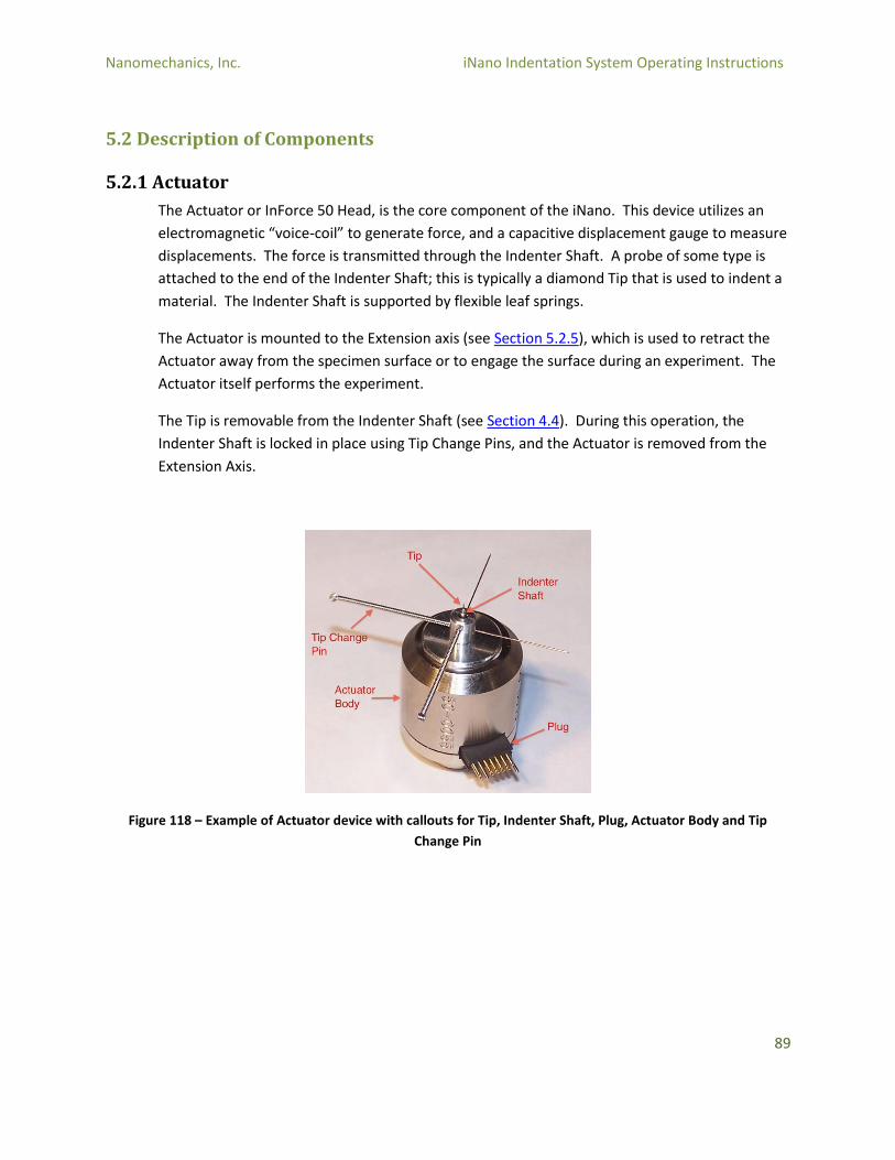
5.2.1 Actuator
The Actuator or InForce 50 Head, is the core component of the iNano. This device utilizes an
electromagnetic “voice-coil” to generate force, and a capacitive displacement gauge to measure
displacements. The force is transmitted through the Indenter Shaft. A probe of some type is
attached to the end of the Indenter Shaft; this is typically a diamond Tip that is used to indent a
material. The Indenter Shaft is supported by flexible leaf springs.
The Actuator is mounted to the Extension axis (see Section 5.2.5), which is used to retract the
Actuator away from the specimen surface or to engage the surface during an experiment. The
Actuator itself performs the experiment.
The Tip is removable from the Indenter Shaft (see Section 4.4). During this operation, the
Indenter Shaft is locked in place using Tip Change Pins, and the Actuator is removed from the
Extension Axis.
Figure 118 – Example of Actuator device with callouts for Tip, Indenter Shaft, Plug, Actuator Body and Tip
Change Pin

Nanomechanics, Inc. iNano Indentation System Operating Instructions
90
5.2.2 Aluminum Specimen
The iNano is provided with an Aluminum Specimen, which is intended for use in the Video
Source Calibration.
Figure 119 – iNano Aluminum Specimen
5.2.3 Cabinet
The Isolation Cabinet of the iNano is designed to reduce the effects of acoustic noise and
thermal changes in the environment. It is a good idea to keep the iNano cabinet closed as much
as possible so that the iNano stays at a constant temperature.
The cabinet hood is opened by lifting under the front panel (below the Nanomechanics logo).
Nanomechanics, Inc. iNano Indentation System Operating Instructions
91
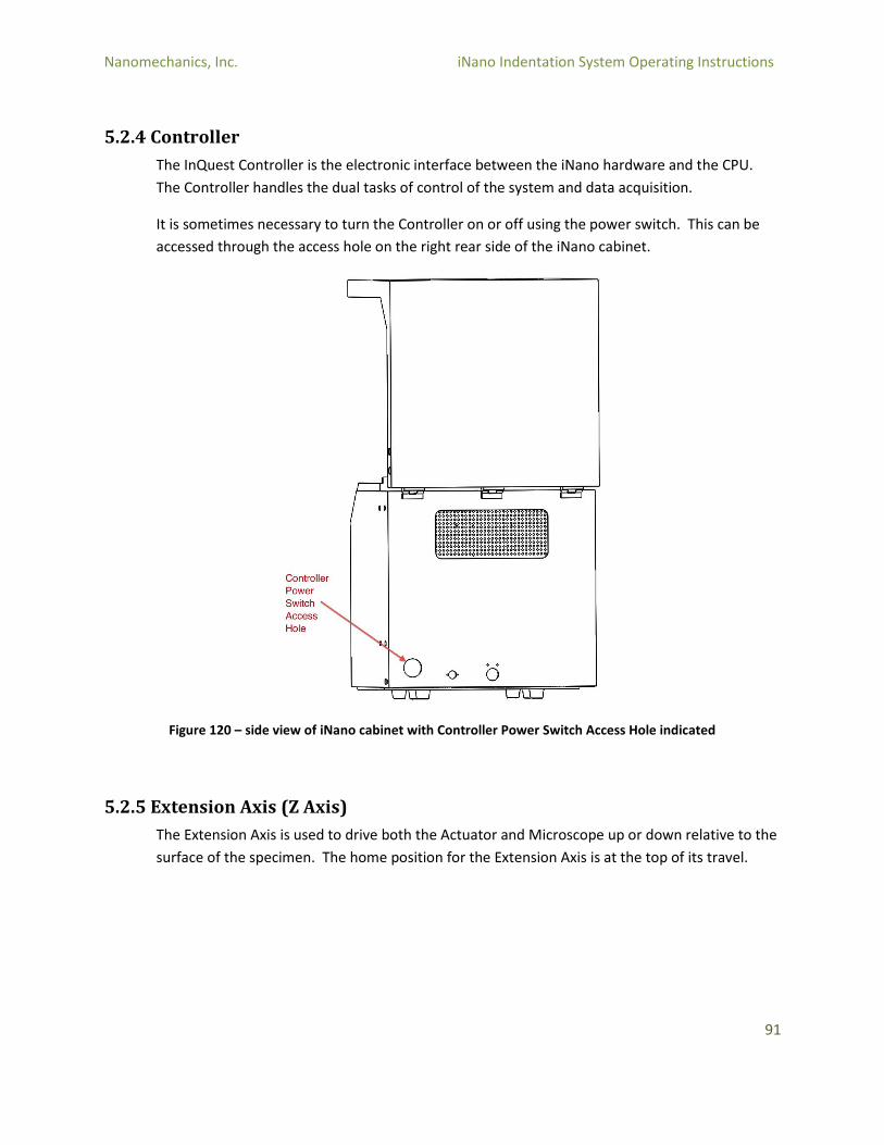
5.2.4 Controller
The InQuest Controller is the electronic interface between the iNano hardware and the CPU.
The Controller handles the dual tasks of control of the system and data acquisition.
It is sometimes necessary to turn the Controller on or off using the power switch. This can be
accessed through the access hole on the right rear side of the iNano cabinet.
Figure 120 – side view of iNano cabinet with Controller Power Switch Access Hole indicated
5.2.5 Extension Axis (Z Axis)
The Extension Axis is used to drive both the Actuator and Microscope up or down relative to the
surface of the specimen. The home position for the Extension Axis is at the top of its travel.
Nanomechanics, Inc. iNano Indentation System Operating Instructions
92
5.2.6 Fused Silica Specimen
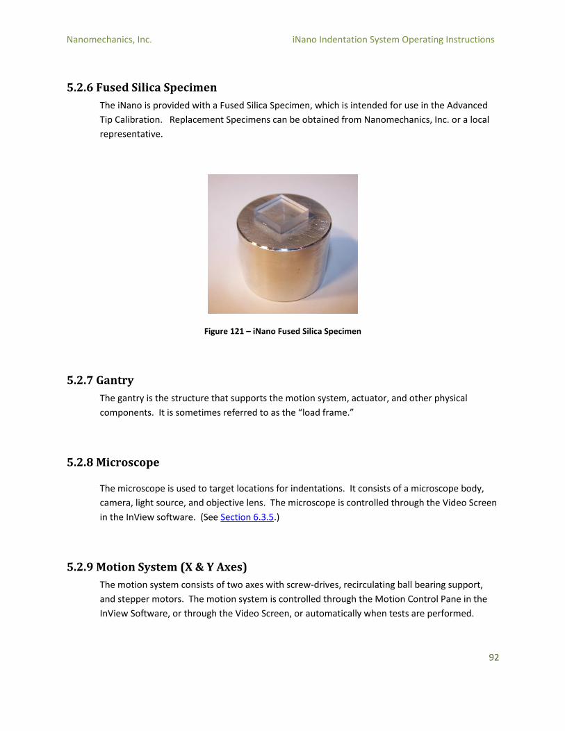
The iNano is provided with a Fused Silica Specimen, which is intended for use in the Advanced
Tip Calibration. Replacement Specimens can be obtained from Nanomechanics, Inc. or a local
representative.
Figure 121 – iNano Fused Silica Specimen
5.2.7 Gantry
The gantry is the structure that supports the motion system, actuator, and other physical
components. It is sometimes referred to as the “load frame.”
5.2.8 Microscope
The microscope is used to target locations for indentations. It consists of a microscope body,
camera, light source, and objective lens. The microscope is controlled through the Video Screen
in the InView software. (See Section 6.3.5.)
5.2.9 Motion System (X & Y Axes)
The motion system consists of two axes with screw-drives, recirculating ball bearing support,
and stepper motors. The motion system is controlled through the Motion Control Pane in the
InView Software, or through the Video Screen, or automatically when tests are performed.
Nanomechanics, Inc. iNano Indentation System Operating Instructions
93
5.2.10 Puck
The Pucks used in the Sample Tray are 1.25” diameter by 1” tall metallurgical mounts.
5.2.11 Sample Tray
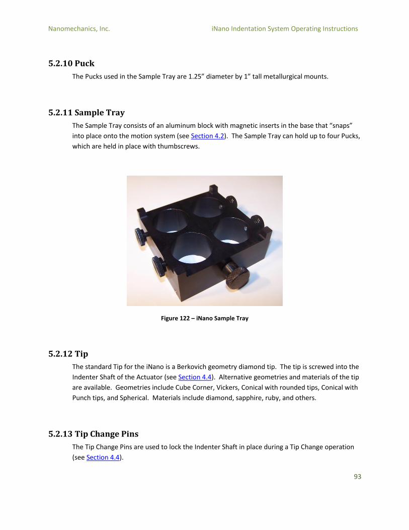
The Sample Tray consists of an aluminum block with magnetic inserts in the base that “snaps”
into place onto the motion system (see Section 4.2). The Sample Tray can hold up to four Pucks,
which are held in place with thumbscrews.
Figure 122 – iNano Sample Tray
5.2.12 Tip
The standard Tip for the iNano is a Berkovich geometry diamond tip. The tip is screwed into the
Indenter Shaft of the Actuator (see Section 4.4). Alternative geometries and materials of the tip
are available. Geometries include Cube Corner, Vickers, Conical with rounded tips, Conical with
Punch tips, and Spherical. Materials include diamond, sapphire, ruby, and others.
5.2.13 Tip Change Pins
The Tip Change Pins are used to lock the Indenter Shaft in place during a Tip Change operation
(see Section 4.4).

Nanomechanics, Inc. iNano Indentation System Operating Instructions
94
5.2.14 Vibration Isolation
Vibration Isolation is accomplished through four dampers that are mounted to the base of the
gantry.
Nanomechanics, Inc. iNano Indentation System Operating Instructions
95
6.0 Software Reference
The InView Software that is bundled with the iNano includes two major applications: the Test program
and the Review program. These are separate applications that work together for the primary tasks of
operating the instruments to generate data, and reviewing and analyzing that data.
6.1 The CPU & Operating Software The iNano is provided with an All-in-one computer utilizing a Windows Operating System. The details of
the computer (CPU) and Operating System (OS) may change from time to time.
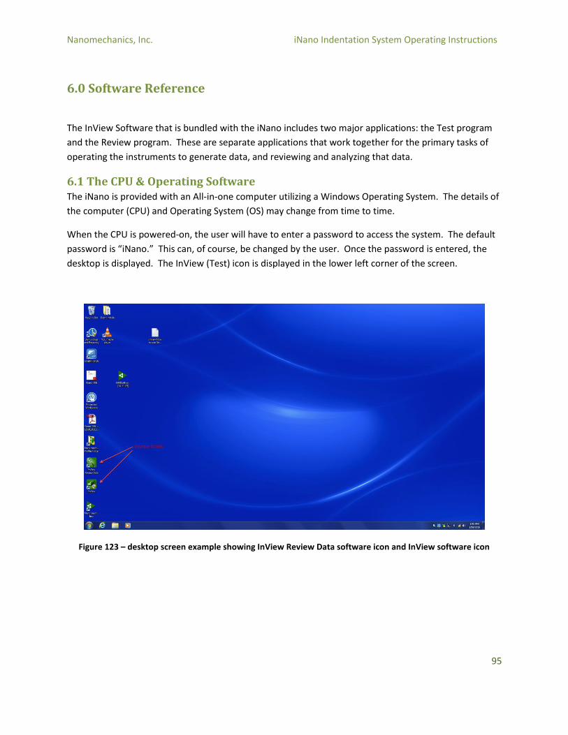
When the CPU is powered-on, the user will have to enter a password to access the system. The default
password is “iNano.” This can, of course, be changed by the user. Once the password is entered, the
desktop is displayed. The InView (Test) icon is displayed in the lower left corner of the screen.
Figure 123 – desktop screen example showing InView Review Data software icon and InView software icon
Nanomechanics, Inc. iNano Indentation System Operating Instructions
96
6.2 Key terminology Test: A test is a single experiment – typically a single indentation.
Method: A Method is an experimental recipe that defines how the instrument operates during a test.
The standard methods are:
Cyclic Indentation To A Load: This method utilizes the “Oliver-Pharr” technique to perform a quasi-static indentation, cycling the load/unload technique to increasing loads until the maximum load is reached.
Dyn. Compression-Const. Disp. Rate: This method utilizes the iNano Dynamics feature and a constant displacement rate to perform an indentation to a desired load or depth.
Dyn. Compression-Const. Load Rate: This method utilizes the iNano Dynamics option and a constant loading rate to perform an indentation to a desired load or depth.
Dyn. Indentation-Const. Strain Rate: This method utilizes the iNano Dynamics option and a constant strain rate to perform an indentation to a desired load or depth.
Low K Dyn. Indentation: This method is similar to the constant strain rate method, but utilizes a model that takes into account the substrate effects.
Operational Check: This method provides a convenient way to ensure that the iNano is functioning properly. The method moves the iNano actuator through its range of motion, and then analyzes that motion for inconsistencies in the linearity and support spring stiffness of the actuator.
User: The User is the Windows OS defined user. The iNano comes with a default user (iNano).
Profile: Since most customers will only utilize a single Windows OS User for accessing the system,
InView defines a “Profile” so that data, methods, and settings can be segregated by different physical
users without resorting to the Windows OS User. That is, there can be multiple Profiles for a single User.
Project: A Project is a way to segregate data under a Profile. This is a good way to group data either by
a project name, or customer name, etc.
Sample: A Sample is a set of tests – most commonly an array of indentations. This can be a single
collection of tests on one specimen, or a series of tests spanning multiple specimens. In MultiSample
mode, the user can define multiple samples as is most convenient. For example, each specimen could
be called a sample, or all of the specimens can be tested in a single sample. The term Sample refers to a
group of tests.

Nanomechanics, Inc. iNano Indentation System Operating Instructions
97
Specimen: A specimen is a physical material – the material that is tested by the iNano.
Settings: Settings contains information about the iNano that may be specific to a Profile. Examples of
such information include the tip parameters, video source calibration, and load frame stiffness.
Channel: Channels are streams of data, such as Displacement, Load, Time, etc.

Nanomechanics, Inc. iNano Indentation System Operating Instructions
98
6.3 InView Test Program
6.3.1 Opening InView Test Program
To open the Test page of InView, double-click on the Inview icon on the desktop
Figure 124 – InView desktop icon
The InView software will open, and will ask for a method to be loaded. By default, the software looks
for the method in the most recently used profile (in this example, the profile is “NMI,” and the method
selected is “Dyn. Indentation Const Strain Rate” located in the Master Methods folder).
Figure 125 – InView software open – select preferred Method
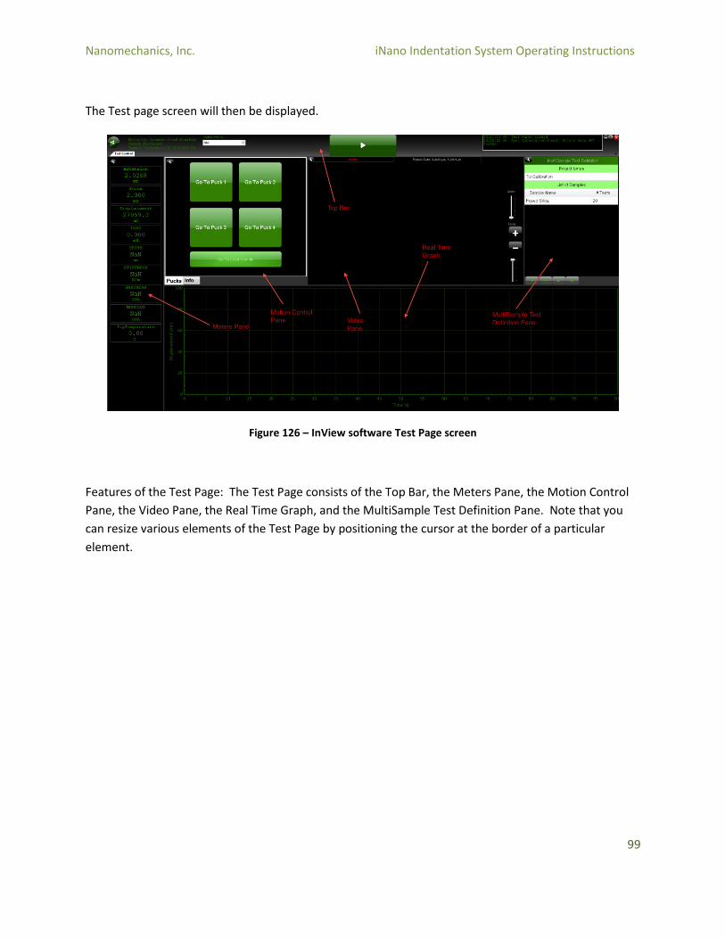
Nanomechanics, Inc. iNano Indentation System Operating Instructions
99
The Test page screen will then be displayed.
Figure 126 – InView software Test Page screen
Features of the Test Page: The Test Page consists of the Top Bar, the Meters Pane, the Motion Control
Pane, the Video Pane, the Real Time Graph, and the MultiSample Test Definition Pane. Note that you
can resize various elements of the Test Page by positioning the cursor at the border of a particular
element.
Nanomechanics, Inc. iNano Indentation System Operating Instructions
100
6.3.2 Top Bar
Figure 127 – Top Bar icon
6.3.2.1 Main Menu
The Main Menu icon is the Nanomechanics logo. Basic functions such as loading methods, samples, or
exiting the software are located here.
Figure 128 – InView Main Menu icon (Nanomechanics logo)
Main Menu: Sample Data
Figure 129 – Main Menu -> Sample Data option
Open: Open allows the user to open a previously saved sample. The sample will be loaded into both the Test Page and the Review Page.
Save: Saves a sample, including all changes that have been made since the sample was run or opened.
Save As: Allows the user to save the sample with a different name.
New: Creates a new Sample
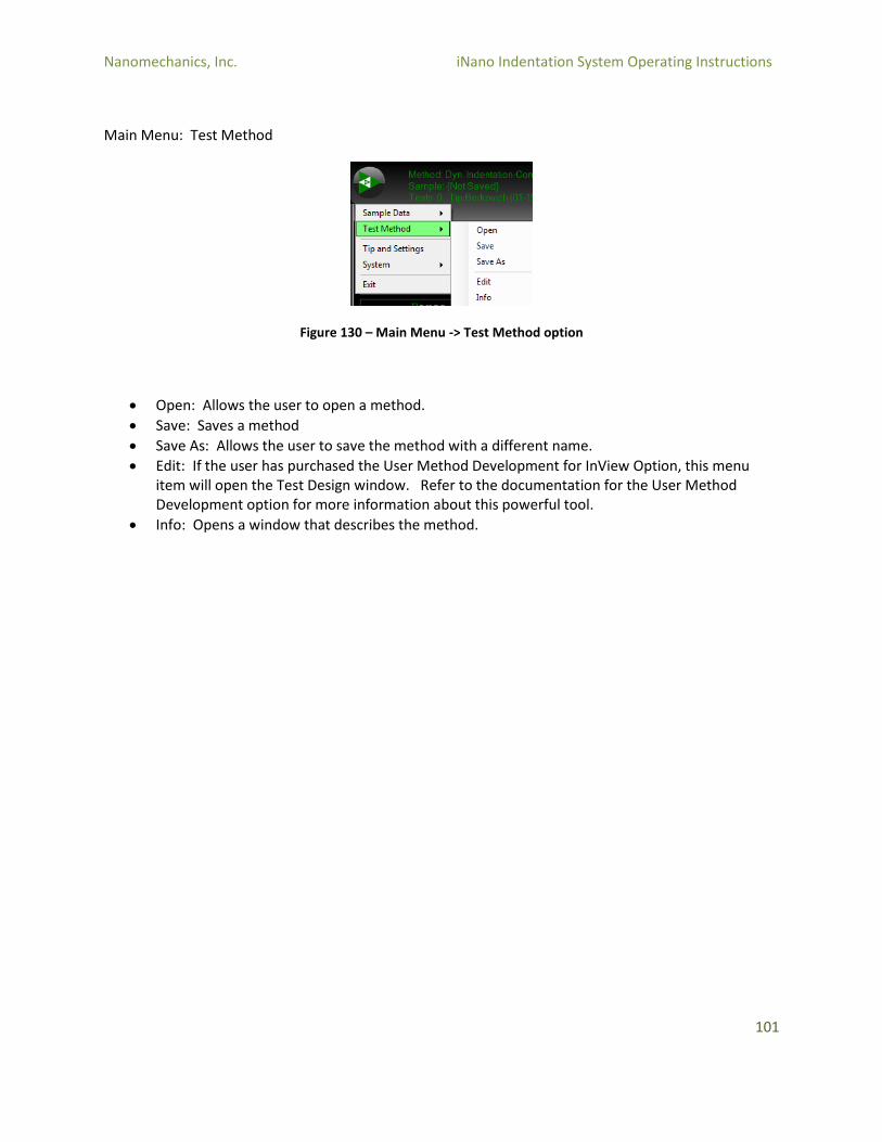
Nanomechanics, Inc. iNano Indentation System Operating Instructions
101
Main Menu: Test Method
Figure 130 – Main Menu -> Test Method option
Open: Allows the user to open a method.
Save: Saves a method
Save As: Allows the user to save the method with a different name.
Edit: If the user has purchased the User Method Development for InView Option, this menu item will open the Test Design window. Refer to the documentation for the User Method Development option for more information about this powerful tool.
Info: Opens a window that describes the method.
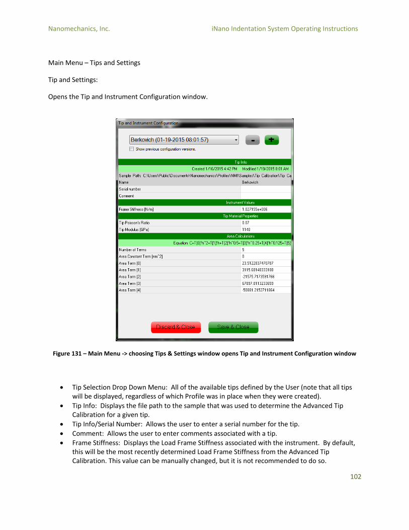
Nanomechanics, Inc. iNano Indentation System Operating Instructions
102
Main Menu – Tips and Settings
Tip and Settings:
Opens the Tip and Instrument Configuration window.
Figure 131 – Main Menu -> choosing Tips & Settings window opens Tip and Instrument Configuration window
Tip Selection Drop Down Menu: All of the available tips defined by the User (note that all tips will be displayed, regardless of which Profile was in place when they were created).
Tip Info: Displays the file path to the sample that was used to determine the Advanced Tip Calibration for a given tip.
Tip Info/Serial Number: Allows the user to enter a serial number for the tip.
Comment: Allows the user to enter comments associated with a tip.
Frame Stiffness: Displays the Load Frame Stiffness associated with the instrument. By default, this will be the most recently determined Load Frame Stiffness from the Advanced Tip Calibration. This value can be manually changed, but it is not recommended to do so.
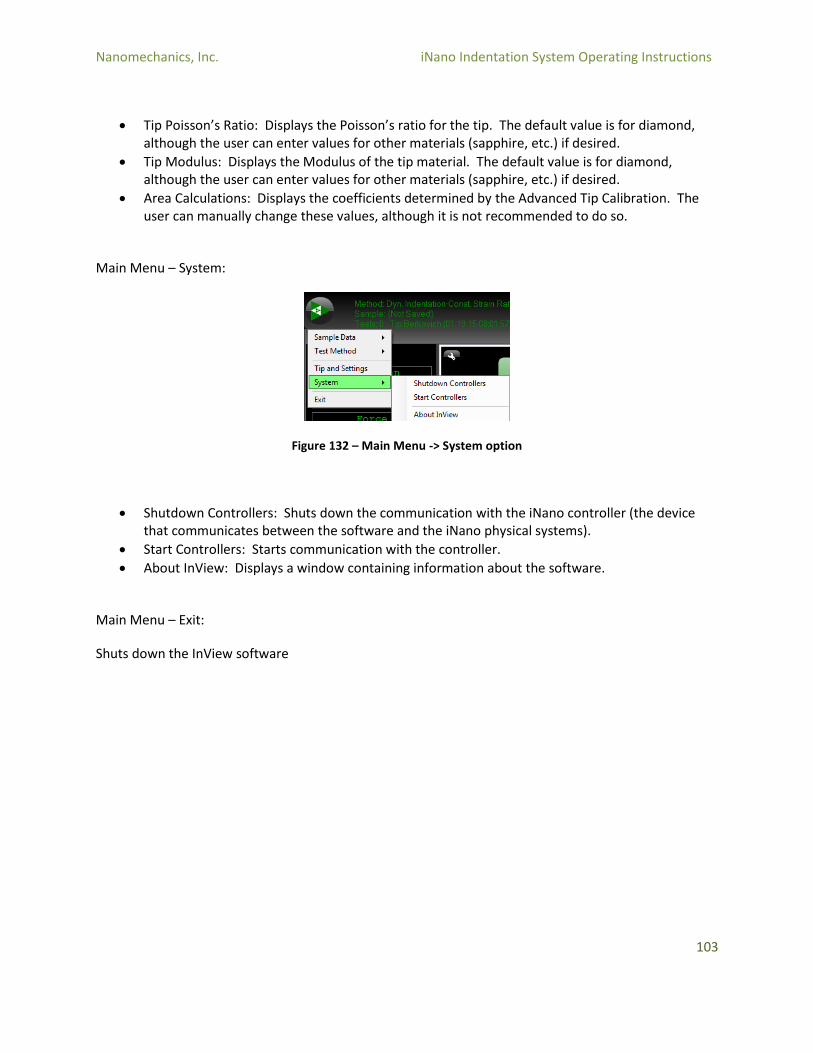
Nanomechanics, Inc. iNano Indentation System Operating Instructions
103
Tip Poisson’s Ratio: Displays the Poisson’s ratio for the tip. The default value is for diamond, although the user can enter values for other materials (sapphire, etc.) if desired.
Tip Modulus: Displays the Modulus of the tip material. The default value is for diamond, although the user can enter values for other materials (sapphire, etc.) if desired.
Area Calculations: Displays the coefficients determined by the Advanced Tip Calibration. The user can manually change these values, although it is not recommended to do so.
Main Menu – System:
Figure 132 – Main Menu -> System option
Shutdown Controllers: Shuts down the communication with the iNano controller (the device that communicates between the software and the iNano physical systems).
Start Controllers: Starts communication with the controller.
About InView: Displays a window containing information about the software.
Main Menu – Exit:
Shuts down the InView software
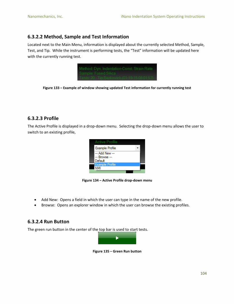
Nanomechanics, Inc. iNano Indentation System Operating Instructions
104
6.3.2.2 Method, Sample and Test Information
Located next to the Main Menu, information is displayed about the currently selected Method, Sample,
Test, and Tip. While the instrument is performing tests, the “Test” information will be updated here
with the currently running test.
Figure 133 – Example of window showing updated Test information for currently running test
6.3.2.3 Profile
The Active Profile is displayed in a drop-down menu. Selecting the drop-down menu allows the user to
switch to an existing profile,
Figure 134 – Active Profile drop-down menu
Add New: Opens a field in which the user can type in the name of the new profile.
Browse: Opens an explorer window in which the user can browse the existing profiles.
6.3.2.4 Run Button
The green run button in the center of the top bar is used to start tests.
Figure 135 – Green Run button
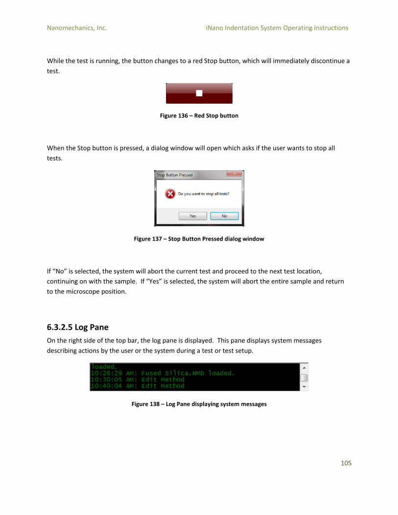
Nanomechanics, Inc. iNano Indentation System Operating Instructions
105
While the test is running, the button changes to a red Stop button, which will immediately discontinue a
test.
Figure 136 – Red Stop button
When the Stop button is pressed, a dialog window will open which asks if the user wants to stop all
tests.
Figure 137 – Stop Button Pressed dialog window
If “No” is selected, the system will abort the current test and proceed to the next test location,
continuing on with the sample. If “Yes” is selected, the system will abort the entire sample and return
to the microscope position.
6.3.2.5 Log Pane
On the right side of the top bar, the log pane is displayed. This pane displays system messages
describing actions by the user or the system during a test or test setup.
Figure 138 – Log Pane displaying system messages
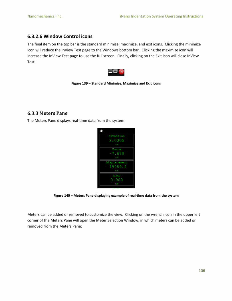
Nanomechanics, Inc. iNano Indentation System Operating Instructions
106
6.3.2.6 Window Control icons
The final item on the top bar is the standard minimize, maximize, and exit icons. Clicking the minimize
icon will reduce the InView Test page to the Windows bottom bar. Clicking the maximize icon will
increase the InView Test page to use the full screen. Finally, clicking on the Exit icon will close InView
Test.
Figure 139 – Standard Minimize, Maximize and Exit icons
6.3.3 Meters Pane
The Meters Pane displays real-time data from the system.
Figure 140 – Meters Pane displaying example of real-time data from the system
Meters can be added or removed to customize the view. Clicking on the wrench icon in the upper left
corner of the Meters Pane will open the Meter Selection Window, in which meters can be added or
removed from the Meters Pane:
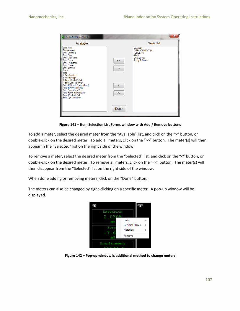
Nanomechanics, Inc. iNano Indentation System Operating Instructions
107
Figure 141 – Item Selection List Forms window with Add / Remove buttons
To add a meter, select the desired meter from the “Available” list, and click on the “>” button, or
double-click on the desired meter. To add all meters, click on the “>>” button. The meter(s) will then
appear in the “Selected” list on the right side of the window.
To remove a meter, select the desired meter from the “Selected” list, and click on the “<” button, or
double-click on the desired meter. To remove all meters, click on the “<<” button. The meter(s) will
then disappear from the “Selected” list on the right side of the window.
When done adding or removing meters, click on the “Done” button. The meters can also be changed by right-clicking on a specific meter. A pop-up window will be
displayed.
Figure 142 – Pop-up window is additional method to change meters
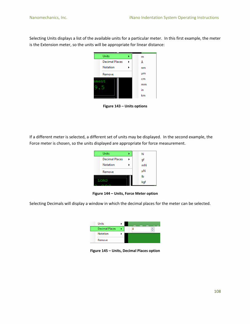
Nanomechanics, Inc. iNano Indentation System Operating Instructions
108
Selecting Units displays a list of the available units for a particular meter. In this first example, the meter
is the Extension meter, so the units will be appropriate for linear distance:
Figure 143 – Units options
If a different meter is selected, a different set of units may be displayed. In the second example, the
Force meter is chosen, so the units displayed are appropriate for force measurement.
Figure 144 – Units, Force Meter option
Selecting Decimals will display a window in which the decimal places for the meter can be selected.
Figure 145 – Units, Decimal Places option

Nanomechanics, Inc. iNano Indentation System Operating Instructions
109
Selecting Notation will allow the user to choose between Standard and Scientific notations.
Figure 146 – Notation options
Finally, note that meters will only display values when there is available data. Some meters (such as
Force, Displacement, etc.) will always show values, while others (such as Depth, Stiffness, Hardness,
etc.) will show “NaN” indicating that there is no data to display. Depth, for example, is only meaningful
during an indentation, in which Depth indicates the displacement into the surface of the specimen.
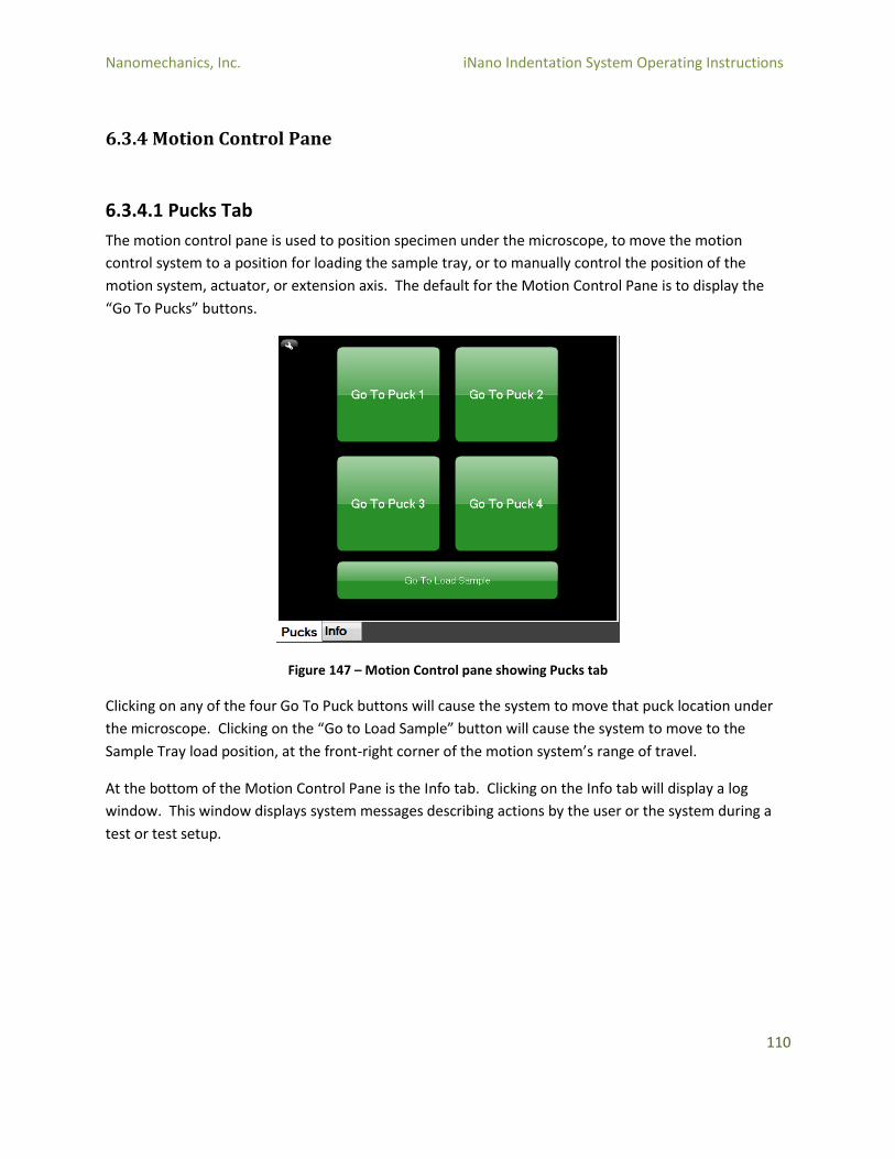
Nanomechanics, Inc. iNano Indentation System Operating Instructions
110
6.3.4 Motion Control Pane
6.3.4.1 Pucks Tab
The motion control pane is used to position specimen under the microscope, to move the motion
control system to a position for loading the sample tray, or to manually control the position of the
motion system, actuator, or extension axis. The default for the Motion Control Pane is to display the
“Go To Pucks” buttons.
Figure 147 – Motion Control pane showing Pucks tab
Clicking on any of the four Go To Puck buttons will cause the system to move that puck location under
the microscope. Clicking on the “Go to Load Sample” button will cause the system to move to the
Sample Tray load position, at the front-right corner of the motion system’s range of travel.
At the bottom of the Motion Control Pane is the Info tab. Clicking on the Info tab will display a log
window. This window displays system messages describing actions by the user or the system during a
test or test setup.
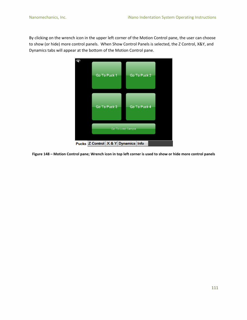
Nanomechanics, Inc. iNano Indentation System Operating Instructions
111
By clicking on the wrench icon in the upper left corner of the Motion Control pane, the user can choose
to show (or hide) more control panels. When Show Control Panels is selected, the Z Control, X&Y, and
Dynamics tabs will appear at the bottom of the Motion Control pane.
Figure 148 – Motion Control pane; Wrench icon in top left corner is used to show or hide more control panels
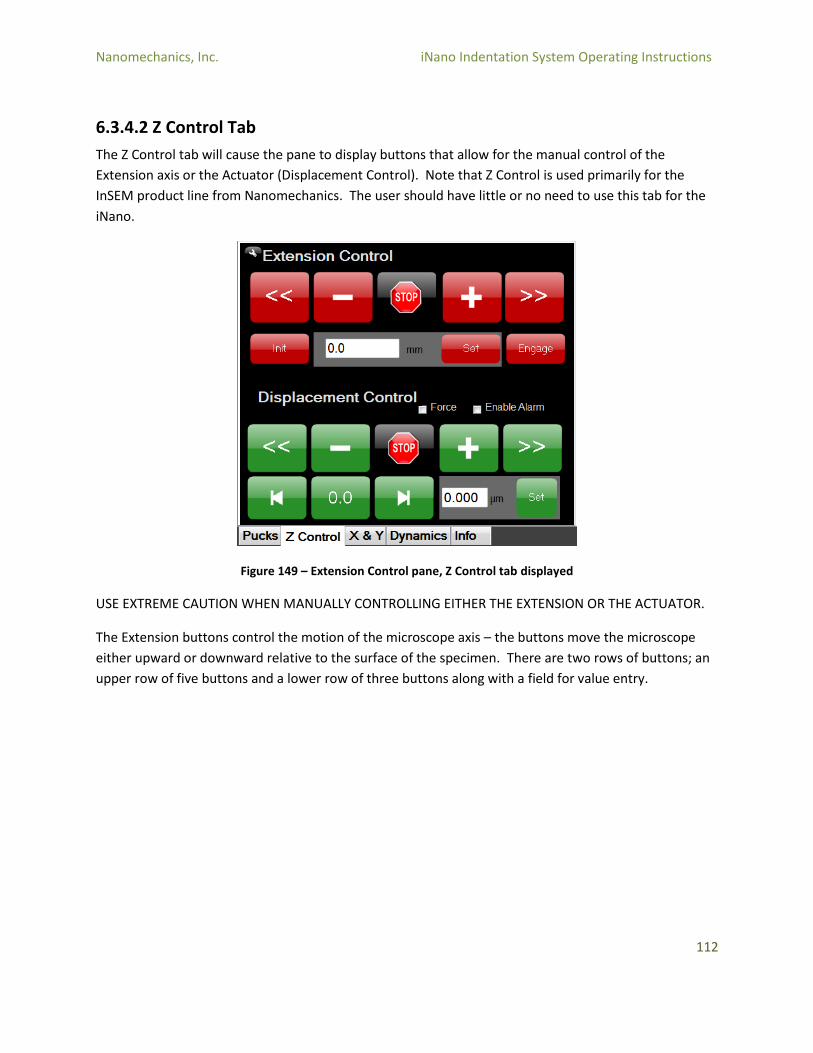
Nanomechanics, Inc. iNano Indentation System Operating Instructions
112
6.3.4.2 Z Control Tab
The Z Control tab will cause the pane to display buttons that allow for the manual control of the
Extension axis or the Actuator (Displacement Control). Note that Z Control is used primarily for the
InSEM product line from Nanomechanics. The user should have little or no need to use this tab for the
iNano.
Figure 149 – Extension Control pane, Z Control tab displayed
USE EXTREME CAUTION WHEN MANUALLY CONTROLLING EITHER THE EXTENSION OR THE ACTUATOR.
The Extension buttons control the motion of the microscope axis – the buttons move the microscope
either upward or downward relative to the surface of the specimen. There are two rows of buttons; an
upper row of five buttons and a lower row of three buttons along with a field for value entry.

Nanomechanics, Inc. iNano Indentation System Operating Instructions
113
Figure 150 – Extension Control pane, all Extension buttons displayed
On the upper row of buttons, there are two directional fast buttons (<< and >>) and two directional slow
buttons (-/+), along with a “Stop” button. Clicking on the (+) button will move the microscope slowly
toward the surface of the specimen. Click on the (-) will move the microscope slowly away from the
surface of the specimen. Clicking on either the (<<) or (>>) button will move the microscope fast either
up or down. Note that all of these buttons are “click & hold” in that motion will only occur while the
cursor is held on the button. Once the mouse click is released, the motion stops.
The Stop button can be used when the Extension axis is moving to cause it to stop immediately.
IT IS IMPORTANT TO NOTE THAT BOTH THE MICROSCOPE AND THE ACTUATOR ARE MOUNTED TO THE
EXTENSION AXIS. This means that when the Extension axis control is used, the actuator is being moved
relative to the specimen surface. Be very certain not to drive the actuator into a hard object, as
extensive damage to the instrument can result.
The lower row of buttons allow for automated control of the Extension axis. The Init button will move
the Extension axis all the way to the top of its travel to find its “home” position and set the Extension
position to zero.
The Set button allows the user to enter an absolute position in the value entry field (in mm). The
Extension axis will then be moved to this location. Refer to the Extension meter to see the current
location of the Extension axis.
Finally, the Engage button will move the Extension axis downward (toward the specimen) while the
software monitors the Actuator displacement. The purpose of this button is to place the indenter in
contact with a specimen surface. This function is used in the InSEM line of products from
Nanomechanics, and will rarely, if ever, have use on the iNano. It is critical that this button not be used
while the microscope is focused on the specimen.
On the lower part of the Z Control screen are the Displacement Control buttons. There are two rows of
buttons; an upper row of five buttons and a lower row of four buttons along with a field for value entry.
In addition, there are two checkboxes for Force and Enable Alarm.

Nanomechanics, Inc. iNano Indentation System Operating Instructions
114
Figure 151 – Displacement Control pane, all Displacement function buttons displayed
Similar to the Extension axis controls, the Displacement controls allow the user to manually control the
position of the indenter column within the Actuator.
On the upper row of buttons, there are two directional fast buttons (<< and >>) and two directional slow
buttons (-/+), along with a “Stop” button. Clicking on the (+) button will move the indenter shaft slowly
toward the surface of the specimen. Click on the (-) will move the indenter shaft slowly away from the
surface of the specimen. Clicking on either the (<<) or (>>) button will move the indenter shaft fast
either up or down. Note that all of these buttons are “click & hold” in that motion will only occur while
the cursor is held on the button. Once the mouse click is released, the motion stops.
The Stop button can be used when the indenter shaft is moving to cause it to stop immediately.
The lower row of buttons allow for automated control of the indenter shaft. The (|<) button will cause
the indenter shaft to move to the top of its travel (away from the specimen surface). The (>|) button
will cause the indenter shaft to move to the bottom of its travel (toward the specimen surface). The
(0.0) button will cause the indenter shaft to move to the center of its travel.
The Set button allows the user to enter an absolute position in the value entry field (in µm). The
indenter shaft will then be moved to this location. Refer to the Displacement meter to see the current
location of the indenter shaft.
Clicking on the “Force” checkbox will change from displacement control to force (load) control of the
indenter shaft. Most of the buttons function in the same way in this mode; the (<<) button will move
the indenter shaft fast upward, the (>|) button will move the indenter to the bottom of its travel, etc.
The “Set” button, however, changes to setting the force (load) at a specific absolute value. Note that
the units next to the value entry field change to mN rather than µm when the Force checkbox is
selected. The (0.0) button will cause the indenter to move to the zero-load position.
The “Enable Alarm” button turns on an audible alarm tone when the indenter shaft is at a displacement
less than 10,000nm. For example, if the indenter shaft was set at a displacement of 20,000nm, and the
extension axis was being used to move the actuator toward the surface of the specimen, when contact
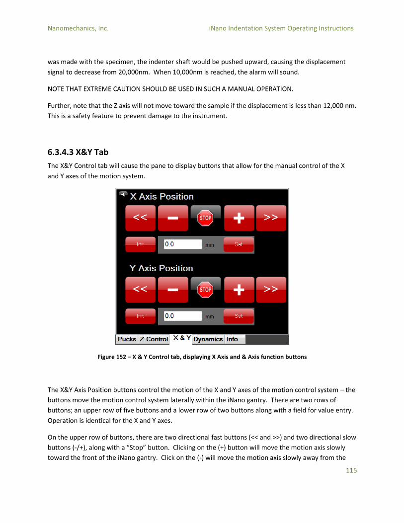
Nanomechanics, Inc. iNano Indentation System Operating Instructions
115
was made with the specimen, the indenter shaft would be pushed upward, causing the displacement
signal to decrease from 20,000nm. When 10,000nm is reached, the alarm will sound.
NOTE THAT EXTREME CAUTION SHOULD BE USED IN SUCH A MANUAL OPERATION.
Further, note that the Z axis will not move toward the sample if the displacement is less than 12,000 nm.
This is a safety feature to prevent damage to the instrument.
6.3.4.3 X&Y Tab
The X&Y Control tab will cause the pane to display buttons that allow for the manual control of the X
and Y axes of the motion system.
Figure 152 – X & Y Control tab, displaying X Axis and & Axis function buttons
The X&Y Axis Position buttons control the motion of the X and Y axes of the motion control system – the
buttons move the motion control system laterally within the iNano gantry. There are two rows of
buttons; an upper row of five buttons and a lower row of two buttons along with a field for value entry.
Operation is identical for the X and Y axes.
On the upper row of buttons, there are two directional fast buttons (<< and >>) and two directional slow
buttons (-/+), along with a “Stop” button. Clicking on the (+) button will move the motion axis slowly
toward the front of the iNano gantry. Click on the (-) will move the motion axis slowly away from the
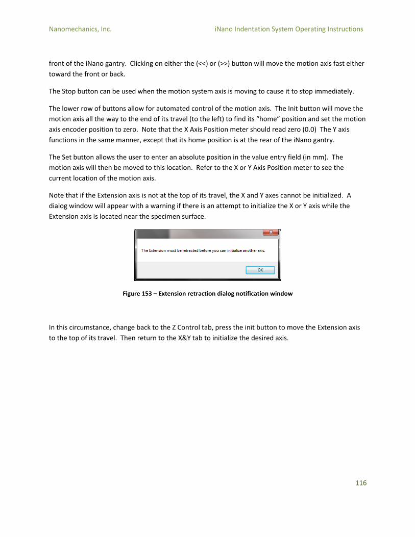
Nanomechanics, Inc. iNano Indentation System Operating Instructions
116
front of the iNano gantry. Clicking on either the (<<) or (>>) button will move the motion axis fast either
toward the front or back.
The Stop button can be used when the motion system axis is moving to cause it to stop immediately.
The lower row of buttons allow for automated control of the motion axis. The Init button will move the
motion axis all the way to the end of its travel (to the left) to find its “home” position and set the motion
axis encoder position to zero. Note that the X Axis Position meter should read zero (0.0) The Y axis
functions in the same manner, except that its home position is at the rear of the iNano gantry.
The Set button allows the user to enter an absolute position in the value entry field (in mm). The
motion axis will then be moved to this location. Refer to the X or Y Axis Position meter to see the
current location of the motion axis.
Note that if the Extension axis is not at the top of its travel, the X and Y axes cannot be initialized. A
dialog window will appear with a warning if there is an attempt to initialize the X or Y axis while the
Extension axis is located near the specimen surface.
Figure 153 – Extension retraction dialog notification window
In this circumstance, change back to the Z Control tab, press the init button to move the Extension axis
to the top of its travel. Then return to the X&Y tab to initialize the desired axis.
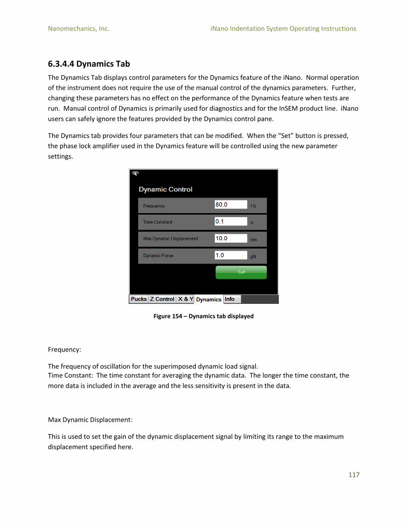
Nanomechanics, Inc. iNano Indentation System Operating Instructions
117
6.3.4.4 Dynamics Tab
The Dynamics Tab displays control parameters for the Dynamics feature of the iNano. Normal operation
of the instrument does not require the use of the manual control of the dynamics parameters. Further,
changing these parameters has no effect on the performance of the Dynamics feature when tests are
run. Manual control of Dynamics is primarily used for diagnostics and for the InSEM product line. iNano
users can safely ignore the features provided by the Dynamics control pane.
The Dynamics tab provides four parameters that can be modified. When the “Set” button is pressed,
the phase lock amplifier used in the Dynamics feature will be controlled using the new parameter
settings.
Figure 154 – Dynamics tab displayed
Frequency:
The frequency of oscillation for the superimposed dynamic load signal. Time Constant: The time constant for averaging the dynamic data. The longer the time constant, the
more data is included in the average and the less sensitivity is present in the data.
Max Dynamic Displacement:
This is used to set the gain of the dynamic displacement signal by limiting its range to the maximum
displacement specified here.

Nanomechanics, Inc. iNano Indentation System Operating Instructions
118
6.3.4.5 Dynamic Force
The amplitude of the superimposed dynamic force oscillation.
6.3.4.6 Info Tab
When the Info tab is selected, the log pane is displayed. This pane displays system messages describing
actions by the user or the system during a test or test setup.
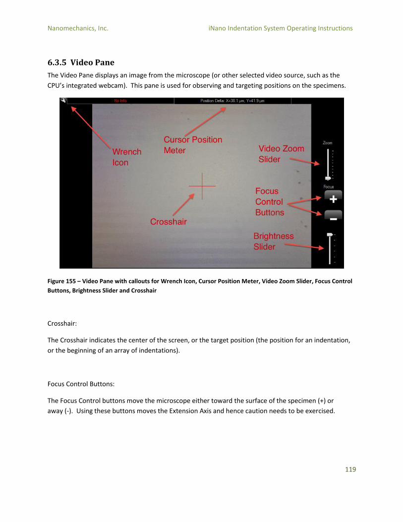
Nanomechanics, Inc. iNano Indentation System Operating Instructions
119
6.3.5 Video Pane
The Video Pane displays an image from the microscope (or other selected video source, such as the
CPU’s integrated webcam). This pane is used for observing and targeting positions on the specimens.
Figure 155 – Video Pane with callouts for Wrench Icon, Cursor Position Meter, Video Zoom Slider, Focus Control
Buttons, Brightness Slider and Crosshair
Crosshair:
The Crosshair indicates the center of the screen, or the target position (the position for an indentation,
or the beginning of an array of indentations).
Focus Control Buttons:
The Focus Control buttons move the microscope either toward the surface of the specimen (+) or
away (-). Using these buttons moves the Extension Axis and hence caution needs to be exercised.
Nanomechanics, Inc. iNano Indentation System Operating Instructions
120
Video Zoom Slider:
The Video Zoom Slider will increase the magnification of the image in the video pane.
Brightness Slider:
The Brightness Slider will increase or decrease the brightness of the image by increasing or decreasing
the intensity of the light. However, as the camera auto-gains, there is limited effect for most materials.
It is preferable to leave this slider at its maximum position.
Cursor Position Meter:
The Cursor Position Meter displays the X and Y coordinates of the cursor relative to the crosshair.
Several functions can be accessed from the Wrench Icon in the upper left corner of the video screen.
Figure 156 – Drop-down menu options of Cursor Position Meter
Select Video Source allows the user to select the video device that will be used to generate the image in
the video pane. There should be no need to change this, although if the camera USB is disconnected
and moved to another USB port, it may be necessary to re-select the video device from the drop down
menu.
Figure 157 – Video Capture Device Settings window options
Nanomechanics, Inc. iNano Indentation System Operating Instructions
121
Camera Configuration:
Selecting this option will display the camera properties window. There are two tabs in this window. The
first, Video Proc Amp allows the user to modify the brightness, contrast, saturation, and other aspects of
the video display. There is normally no need to modify these settings.
Figure 158 – SCMOS1300KPA Properties window with Video Proc Amp tab selected
The second tab, Camera Control, allows the user to modify the zoom, exposure, and other aspects of the
video camera. There is normally no need to modify these settings.
Figure 159 – SCMOS1300KPA Properties window with Camera Control tab selected
Nanomechanics, Inc. iNano Indentation System Operating Instructions
122
Save Image To File:
This function allows the user to save the image currently displayed on the video pane. A dialog window
will appear to select the folder to store the image file. The location will default to the current Profile.
The default image format is JPEG, although PNG and BMP are also available.
Figure 160 – Save As dialog window; **be aware that the location will default to the current Profile**
Calibrate Video Source:
This function allows for determination of the distance between the microscope and the indenter, which
is necessary for correct targeting of indentation locations, and calibration of the video screen. Refer to
Section 4.3 for details on performing these calibrations.
Several functions can be accessed by right-clicking on the video screen:
Figure 161 – Calibrate Video Source functions displayed
Nanomechanics, Inc. iNano Indentation System Operating Instructions
123
Remove Backlash:
This function moves the motion system in a pattern so that backlash in the X and Y axes of the motion
system is removed. Backlash refers to the error that occurs in motion systems caused by the reversal of
direction, and due to “slack” or “clearances” in the motion system.
Move Relative:
This function allows the user to move the motion system relative to the current position of the
crosshairs. The following image shows a 50 µm relative move that was made by entering 50.0 in the
value entry field, and clicking on the right hand side arrow button (>)
Figure 162 – Example of a 50 µm relative move being initiated by entering 50.0 in the value entry field
Figure 163 – Example of a 50 µm relative move implemented, movement to center of field displayed
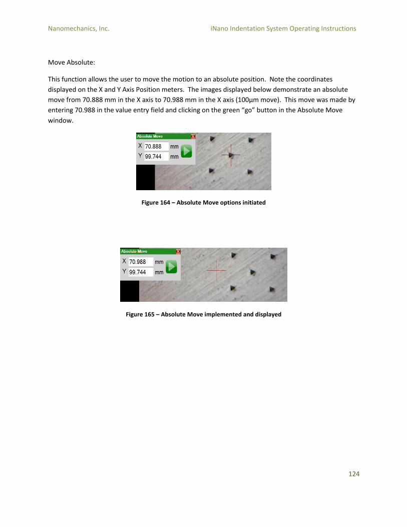
Nanomechanics, Inc. iNano Indentation System Operating Instructions
124
Move Absolute:
This function allows the user to move the motion to an absolute position. Note the coordinates
displayed on the X and Y Axis Position meters. The images displayed below demonstrate an absolute
move from 70.888 mm in the X axis to 70.988 mm in the X axis (100µm move). This move was made by
entering 70.988 in the value entry field and clicking on the green “go” button in the Absolute Move
window.
Figure 164 – Absolute Move options initiated
Figure 165 – Absolute Move implemented and displayed
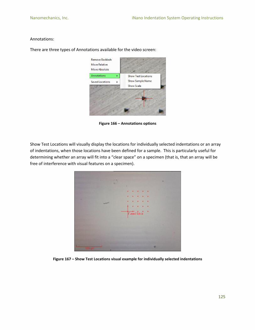
Nanomechanics, Inc. iNano Indentation System Operating Instructions
125
Annotations:
There are three types of Annotations available for the video screen:
Figure 166 – Annotations options
Show Test Locations will visually display the locations for individually selected indentations or an array
of indentations, when those locations have been defined for a sample. This is particularly useful for
determining whether an array will fit into a “clear space” on a specimen (that is, that an array will be
free of interference with visual features on a specimen).
Figure 167 – Show Test Locations visual example for individually selected indentations

Nanomechanics, Inc. iNano Indentation System Operating Instructions
126
Show Sample Name will display the sample name at the locations for selected indentations. This can be
very useful when multiple samples are used on a single specimen. In the example below, two samples
are visible in the same field of view. The first, Fused Silica, is a 5 x 5 array with 20 µm spacing between
indents using the Dyn. Indentation – Const. Strain Rate method. The second, Fused Silica Cycle Method
is a 3 x 3 array with 20 µm spacing, using the Cyclic Indentation to a Load method. The user has defined
the sample name for the second sample so that the different method is clearly visible in the annotation.
Figure 168 – Example of Show Sample Name option, with Fused Silica and Fused Silica Cycle Method displayed
Show Scale:
As is visible in the images above, the Show Scale annotation will display a scale marker in the lower left
corner of the screen.
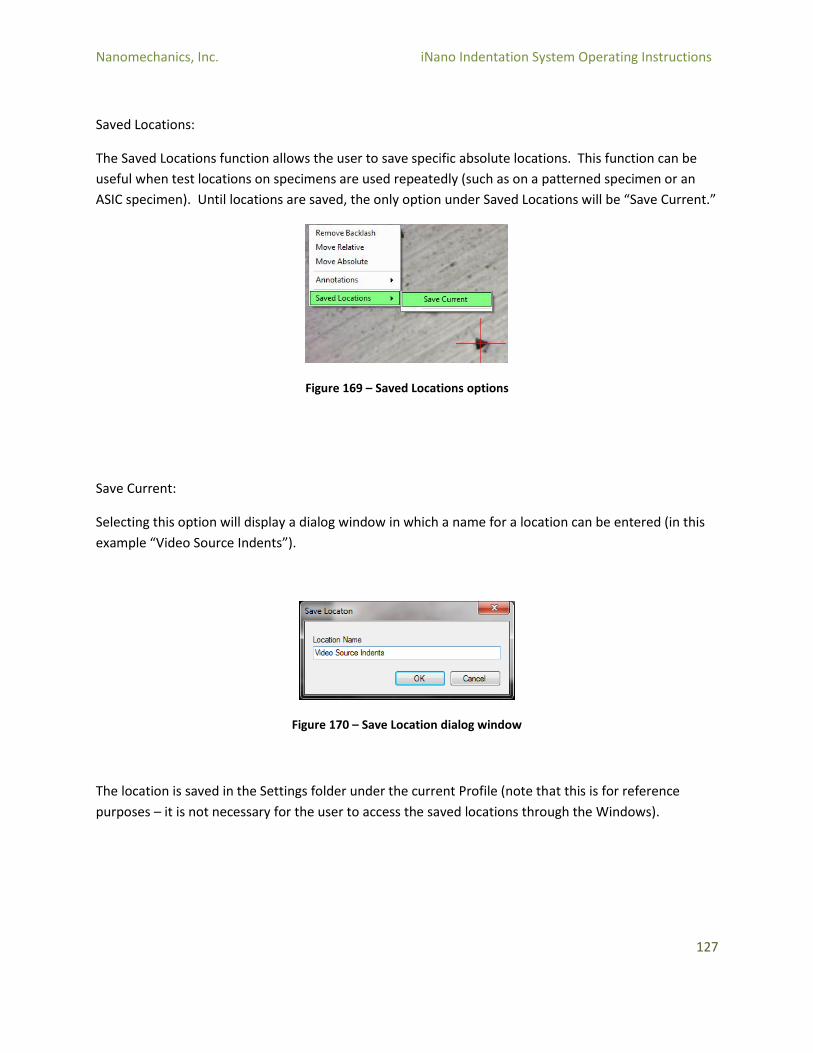
Nanomechanics, Inc. iNano Indentation System Operating Instructions
127
Saved Locations:
The Saved Locations function allows the user to save specific absolute locations. This function can be
useful when test locations on specimens are used repeatedly (such as on a patterned specimen or an
ASIC specimen). Until locations are saved, the only option under Saved Locations will be “Save Current.”
Figure 169 – Saved Locations options
Save Current:
Selecting this option will display a dialog window in which a name for a location can be entered (in this
example “Video Source Indents”).
Figure 170 – Save Location dialog window
The location is saved in the Settings folder under the current Profile (note that this is for reference
purposes – it is not necessary for the user to access the saved locations through the Windows).

Nanomechanics, Inc. iNano Indentation System Operating Instructions
128
Once a location has been saved, then that location will be available in the Saved Locations menu. In the
example below, “Video Source Indents” is available for use. There are three options when locations
have been saved.
Figure 171 – Saved Locations options
Go To:
This function will move the motion system to the saved location.
Update:
This function allows the user to update the saved location to the current location (of the crosshair).
Remove:
This function removes a saved location. This action is permanent and cannot be undone.
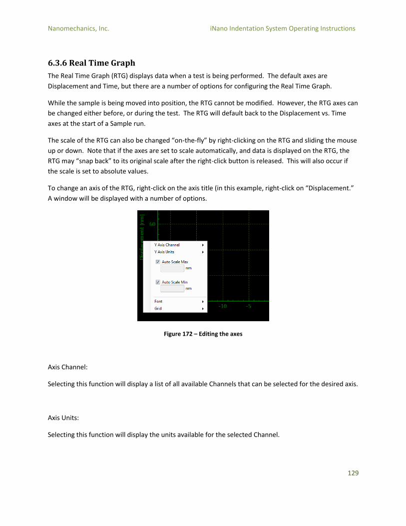
Nanomechanics, Inc. iNano Indentation System Operating Instructions
129
6.3.6 Real Time Graph
The Real Time Graph (RTG) displays data when a test is being performed. The default axes are
Displacement and Time, but there are a number of options for configuring the Real Time Graph.
While the sample is being moved into position, the RTG cannot be modified. However, the RTG axes can
be changed either before, or during the test. The RTG will default back to the Displacement vs. Time
axes at the start of a Sample run.
The scale of the RTG can also be changed “on-the-fly” by right-clicking on the RTG and sliding the mouse
up or down. Note that if the axes are set to scale automatically, and data is displayed on the RTG, the
RTG may “snap back” to its original scale after the right-click button is released. This will also occur if
the scale is set to absolute values.
To change an axis of the RTG, right-click on the axis title (in this example, right-click on “Displacement.”
A window will be displayed with a number of options.
Figure 172 – Editing the axes
Axis Channel:
Selecting this function will display a list of all available Channels that can be selected for the desired axis.
Axis Units:
Selecting this function will display the units available for the selected Channel.

Nanomechanics, Inc. iNano Indentation System Operating Instructions
130
Auto Scale Max and Min:
When the checkbox by the Auto Scale is selected, the RTG will automatically be rescaled as necessary to
display the available data. When the checkbox is unchecked, the maximum or minimum scale of the axis
will be set to the value entered in the value entry field. Note that the units are contextual (i.e.,
Displacement will be displayed as the selected Axis Unit, such as nm or mm, etc.).
Font:
The Font size can be increased or decreased as desired.
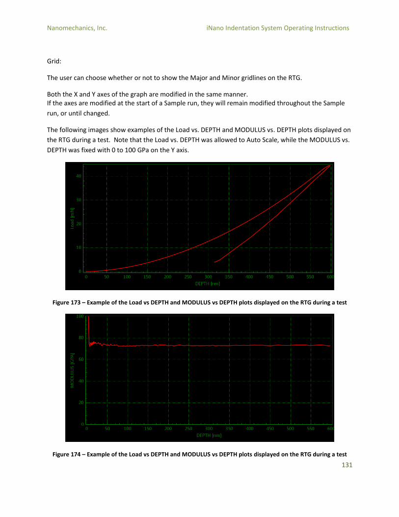
Nanomechanics, Inc. iNano Indentation System Operating Instructions
131
Grid:
The user can choose whether or not to show the Major and Minor gridlines on the RTG.
Both the X and Y axes of the graph are modified in the same manner. If the axes are modified at the start of a Sample run, they will remain modified throughout the Sample
run, or until changed.
The following images show examples of the Load vs. DEPTH and MODULUS vs. DEPTH plots displayed on
the RTG during a test. Note that the Load vs. DEPTH was allowed to Auto Scale, while the MODULUS vs.
DEPTH was fixed with 0 to 100 GPa on the Y axis.
Figure 173 – Example of the Load vs DEPTH and MODULUS vs DEPTH plots displayed on the RTG during a test
Figure 174 – Example of the Load vs DEPTH and MODULUS vs DEPTH plots displayed on the RTG during a test
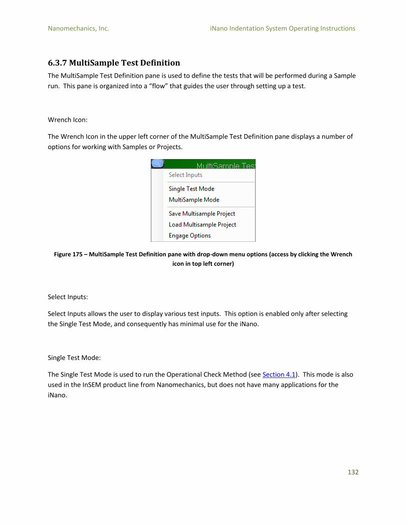
Nanomechanics, Inc. iNano Indentation System Operating Instructions
132
6.3.7 MultiSample Test Definition
The MultiSample Test Definition pane is used to define the tests that will be performed during a Sample
run. This pane is organized into a “flow” that guides the user through setting up a test.
Wrench Icon:
The Wrench Icon in the upper left corner of the MultiSample Test Definition pane displays a number of
options for working with Samples or Projects.
Figure 175 – MultiSample Test Definition pane with drop-down menu options (access by clicking the Wrench
icon in top left corner)
Select Inputs:
Select Inputs allows the user to display various test inputs. This option is enabled only after selecting
the Single Test Mode, and consequently has minimal use for the iNano.
Single Test Mode:
The Single Test Mode is used to run the Operational Check Method (see Section 4.1). This mode is also
used in the InSEM product line from Nanomechanics, but does not have many applications for the
iNano.

Nanomechanics, Inc. iNano Indentation System Operating Instructions
133
MultiSample Mode:
The Multisample Mode is the primary means of setting up tests on the iNano. A Sample is a set of tests
– most commonly an array of indentations. This can be a single collection of tests on one specimen, or a
series of tests spanning multiple specimens. In MultiSample mode, the user can define multiple samples
as is most convenient. For example, each specimen could be called a sample, or all of the specimens can
be tested in a single sample. When the instrument is set to operate in Multisample mode, the
MultiSample Test Definition pane displays a series of windows, described hereafter, that are used to set
up the test.
Save Multisample Project:
The user can save a Multisample Project. This allows for the re-use of standard test setup or the use of a
Project as the starting point for a new Project. When this function is selected, a dialog window will open
directing the user to enter a filename under which to save the Project.
Figure 176 – Saving a MultiSample Project
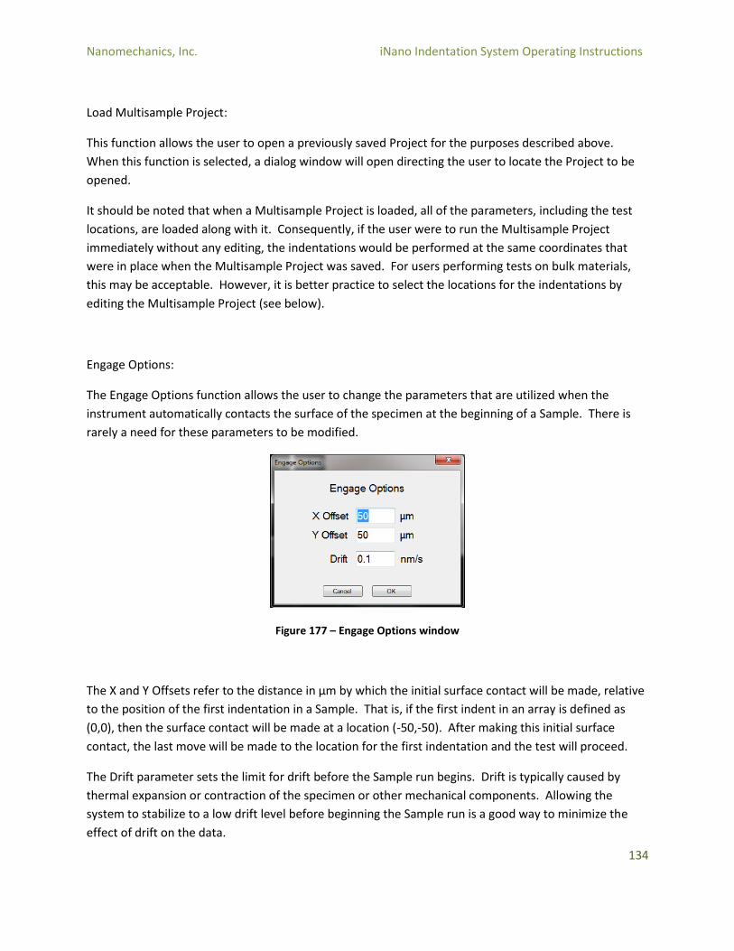
Nanomechanics, Inc. iNano Indentation System Operating Instructions
134
Load Multisample Project:
This function allows the user to open a previously saved Project for the purposes described above.
When this function is selected, a dialog window will open directing the user to locate the Project to be
opened.
It should be noted that when a Multisample Project is loaded, all of the parameters, including the test
locations, are loaded along with it. Consequently, if the user were to run the Multisample Project
immediately without any editing, the indentations would be performed at the same coordinates that
were in place when the Multisample Project was saved. For users performing tests on bulk materials,
this may be acceptable. However, it is better practice to select the locations for the indentations by
editing the Multisample Project (see below).
Engage Options:
The Engage Options function allows the user to change the parameters that are utilized when the
instrument automatically contacts the surface of the specimen at the beginning of a Sample. There is
rarely a need for these parameters to be modified.
Figure 177 – Engage Options window
The X and Y Offsets refer to the distance in µm by which the initial surface contact will be made, relative
to the position of the first indentation in a Sample. That is, if the first indent in an array is defined as
(0,0), then the surface contact will be made at a location (-50,-50). After making this initial surface
contact, the last move will be made to the location for the first indentation and the test will proceed.
The Drift parameter sets the limit for drift before the Sample run begins. Drift is typically caused by
thermal expansion or contraction of the specimen or other mechanical components. Allowing the
system to stabilize to a low drift level before beginning the Sample run is a good way to minimize the
effect of drift on the data.

Nanomechanics, Inc. iNano Indentation System Operating Instructions
135
Test Setup in Multisample Mode:
When the instrument is set to operate in Multisample mode, the MultiSample Test Definition pane
displays a series of windows that are used to set up the test.
MultiSample Test Definition Window:
The first window displayed is the MultiSample Test Definition Window. A new Project Name can be
entered here, or a previously defined Project can be selected from the drop down menu.
Figure 178 – MultiSample Test Definition window; new Project Name can be entered or selected from drop-
down menu
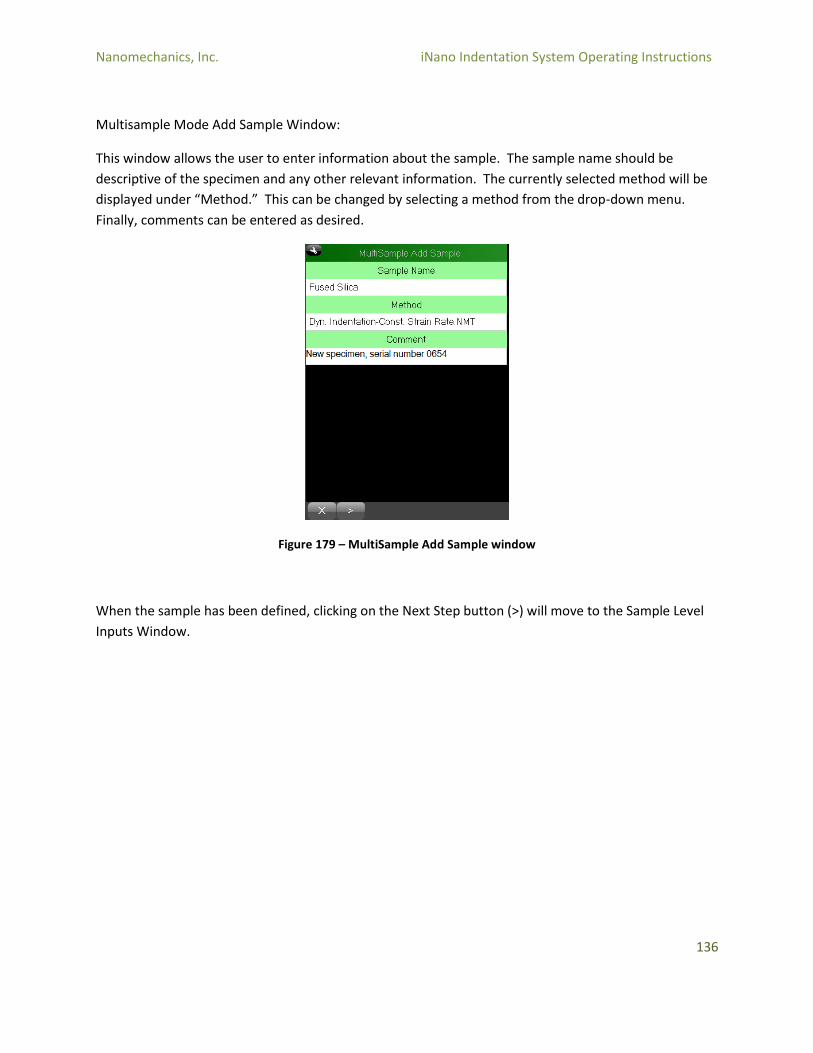
Nanomechanics, Inc. iNano Indentation System Operating Instructions
136
Multisample Mode Add Sample Window:
This window allows the user to enter information about the sample. The sample name should be
descriptive of the specimen and any other relevant information. The currently selected method will be
displayed under “Method.” This can be changed by selecting a method from the drop-down menu.
Finally, comments can be entered as desired.
Figure 179 – MultiSample Add Sample window
When the sample has been defined, clicking on the Next Step button (>) will move to the Sample Level
Inputs Window.

Nanomechanics, Inc. iNano Indentation System Operating Instructions
137
Sample Level Inputs Window:
This window displays the parameters that can be edited by the user for a given method. If the Poisson’s
Ratio of the sample is known, enter it here (the default will work well for most engineering materials).
Most commonly, the user will edit the Test Level Inputs: target load or depth. Depending on the
method, the load rate, displacement rate, or strain rate may also be edited.
Figure 180 – Sample Level Inputs window with parameters displayed
Once all of the inputs have been entered, or the defaults left in place, clicking on the Next Step button
(>) will move to the Define Test Locations Window.
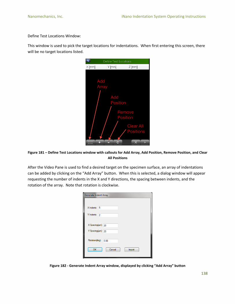
Nanomechanics, Inc. iNano Indentation System Operating Instructions
138
Define Test Locations Window:
This window is used to pick the target locations for indentations. When first entering this screen, there
will be no target locations listed.
Figure 181 – Define Test Locations window with callouts for Add Array, Add Position, Remove Position, and Clear
All Positions
After the Video Pane is used to find a desired target on the specimen surface, an array of indentations
can be added by clicking on the “Add Array” button. When this is selected, a dialog window will appear
requesting the number of indents in the X and Y directions, the spacing between indents, and the
rotation of the array. Note that rotation is clockwise.
Figure 182 - Generate Indent Array window, displayed by clicking “Add Array” button
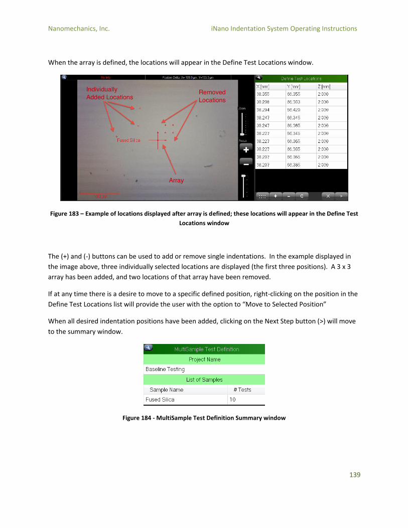
Nanomechanics, Inc. iNano Indentation System Operating Instructions
139
When the array is defined, the locations will appear in the Define Test Locations window.
Figure 183 – Example of locations displayed after array is defined; these locations will appear in the Define Test
Locations window
The (+) and (-) buttons can be used to add or remove single indentations. In the example displayed in
the image above, three individually selected locations are displayed (the first three positions). A 3 x 3
array has been added, and two locations of that array have been removed.
If at any time there is a desire to move to a specific defined position, right-clicking on the position in the
Define Test Locations list will provide the user with the option to “Move to Selected Position”
When all desired indentation positions have been added, clicking on the Next Step button (>) will move
to the summary window.
Figure 184 - MultiSample Test Definition Summary window
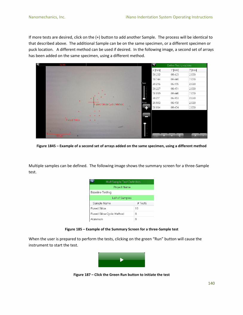
Nanomechanics, Inc. iNano Indentation System Operating Instructions
140
If more tests are desired, click on the (+) button to add another Sample. The process will be identical to
that described above. The additional Sample can be on the same specimen, or a different specimen or
puck location. A different method can be used if desired. In the following image, a second set of arrays
has been added on the same specimen, using a different method.
Figure 1845 – Example of a second set of arrays added on the same specimen, using a different method
Multiple samples can be defined. The following image shows the summary screen for a three-Sample
test.
Figure 185 – Example of the Summary Screen for a three-Sample test
When the user is prepared to perform the tests, clicking on the green “Run” button will cause the
instrument to start the test.
Figure 187 – Click the Green Run button to initiate the test
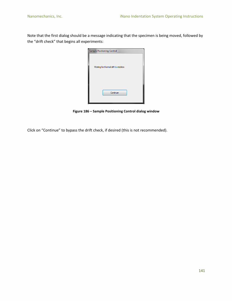
Nanomechanics, Inc. iNano Indentation System Operating Instructions
141
Note that the first dialog should be a message indicating that the specimen is being moved, followed by
the “drift check” that begins all experiments:
Figure 186 – Sample Positioning Control dialog window
Click on “Continue” to bypass the drift check, if desired (this is not recommended).

Nanomechanics, Inc. iNano Indentation System Operating Instructions
142
6.4 InView Review Program
6.4.1 InView Opening
To open the Review Page of InView, double-click on the InView Review icon on the desktop.
Figure 187 – InView Review desktop icon
The Review Page will open, and will ask for a method or sample to be loaded.
Figure 188 – Load Method or Sample request on Review Page
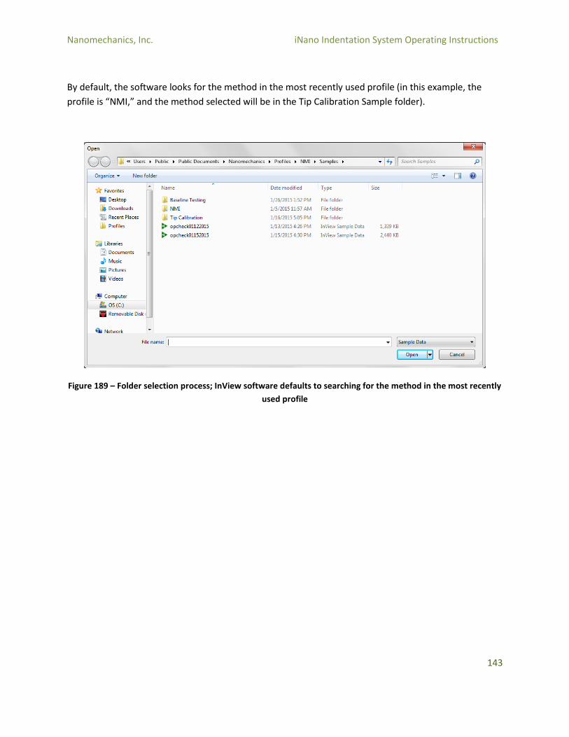
Nanomechanics, Inc. iNano Indentation System Operating Instructions
143
By default, the software looks for the method in the most recently used profile (in this example, the
profile is “NMI,” and the method selected will be in the Tip Calibration Sample folder).
Figure 189 – Folder selection process; InView software defaults to searching for the method in the most recently
used profile
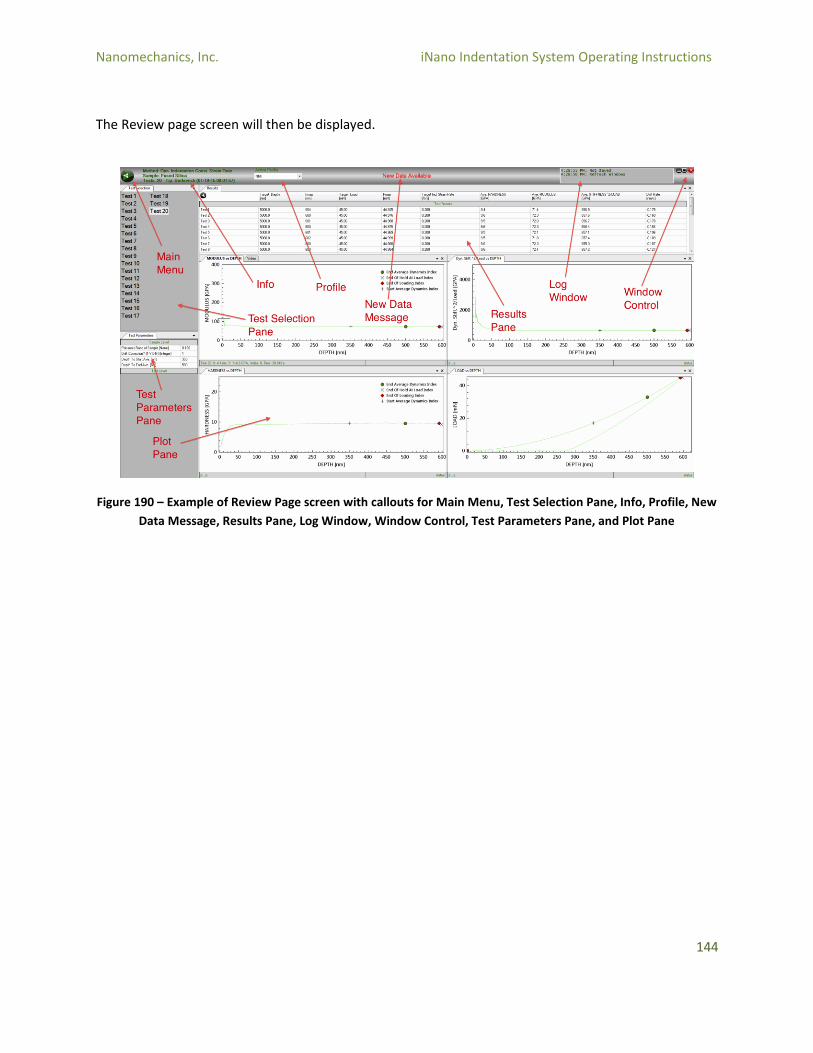
Nanomechanics, Inc. iNano Indentation System Operating Instructions
144
The Review page screen will then be displayed.
Figure 190 – Example of Review Page screen with callouts for Main Menu, Test Selection Pane, Info, Profile, New
Data Message, Results Pane, Log Window, Window Control, Test Parameters Pane, and Plot Pane
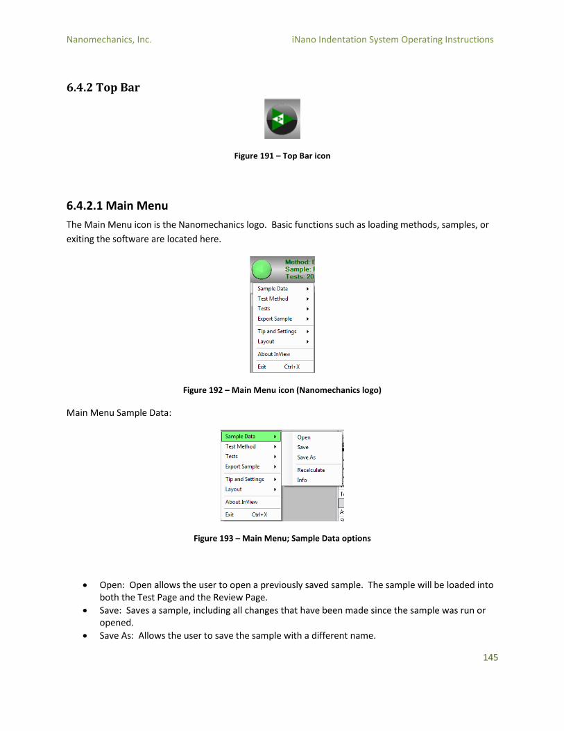
Nanomechanics, Inc. iNano Indentation System Operating Instructions
145
6.4.2 Top Bar
Figure 191 – Top Bar icon
6.4.2.1 Main Menu
The Main Menu icon is the Nanomechanics logo. Basic functions such as loading methods, samples, or
exiting the software are located here.
Figure 192 – Main Menu icon (Nanomechanics logo)
Main Menu Sample Data:
Figure 193 – Main Menu; Sample Data options
Open: Open allows the user to open a previously saved sample. The sample will be loaded into both the Test Page and the Review Page.
Save: Saves a sample, including all changes that have been made since the sample was run or opened.
Save As: Allows the user to save the sample with a different name.
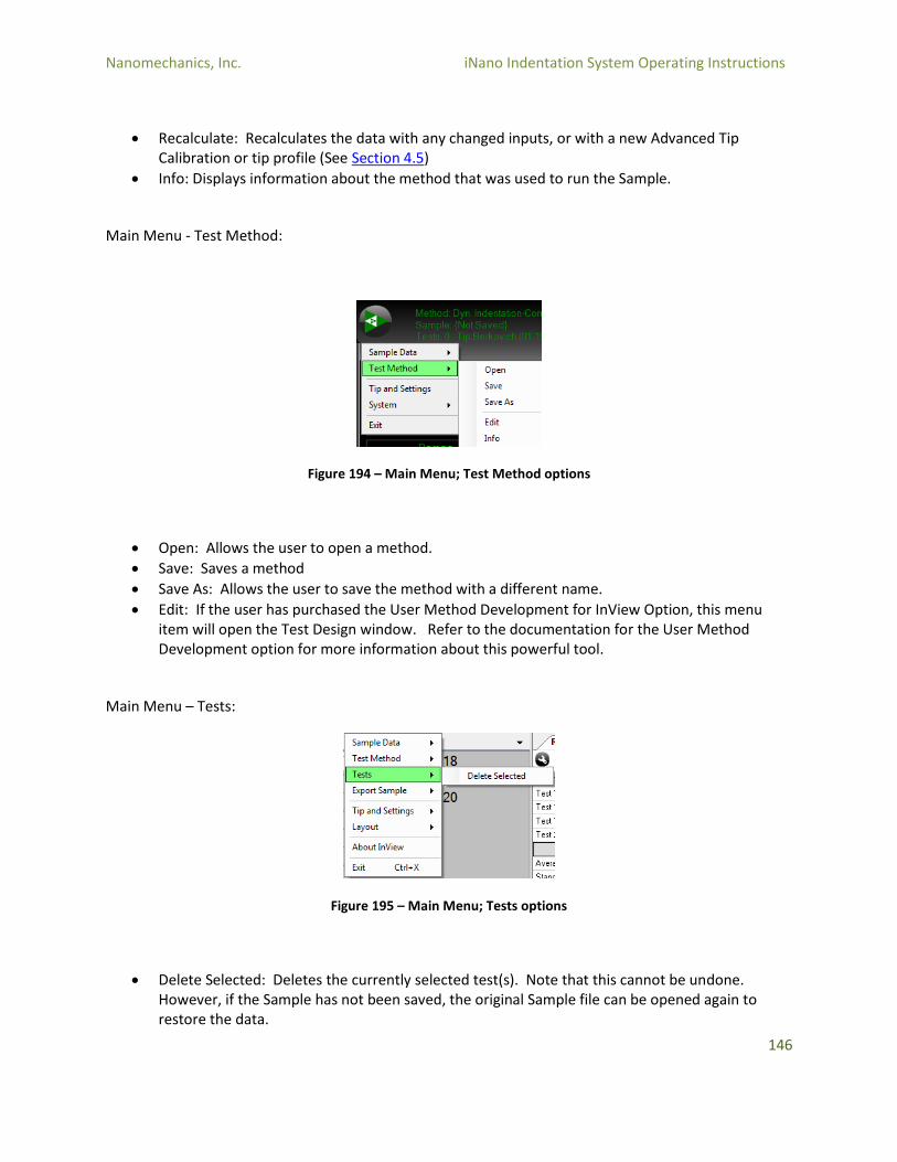
Nanomechanics, Inc. iNano Indentation System Operating Instructions
146
Recalculate: Recalculates the data with any changed inputs, or with a new Advanced Tip Calibration or tip profile (See Section 4.5)
Info: Displays information about the method that was used to run the Sample.
Main Menu - Test Method:
Figure 194 – Main Menu; Test Method options
Open: Allows the user to open a method.
Save: Saves a method
Save As: Allows the user to save the method with a different name.
Edit: If the user has purchased the User Method Development for InView Option, this menu item will open the Test Design window. Refer to the documentation for the User Method Development option for more information about this powerful tool.
Main Menu – Tests:
Figure 195 – Main Menu; Tests options
Delete Selected: Deletes the currently selected test(s). Note that this cannot be undone. However, if the Sample has not been saved, the original Sample file can be opened again to restore the data.
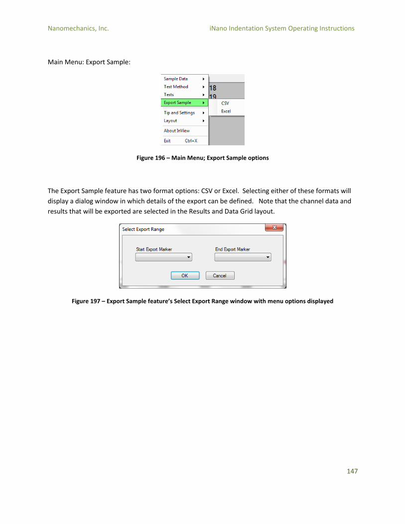
Nanomechanics, Inc. iNano Indentation System Operating Instructions
147
Main Menu: Export Sample:
Figure 196 – Main Menu; Export Sample options
The Export Sample feature has two format options: CSV or Excel. Selecting either of these formats will
display a dialog window in which details of the export can be defined. Note that the channel data and
results that will be exported are selected in the Results and Data Grid layout.
Figure 197 – Export Sample feature’s Select Export Range window with menu options displayed
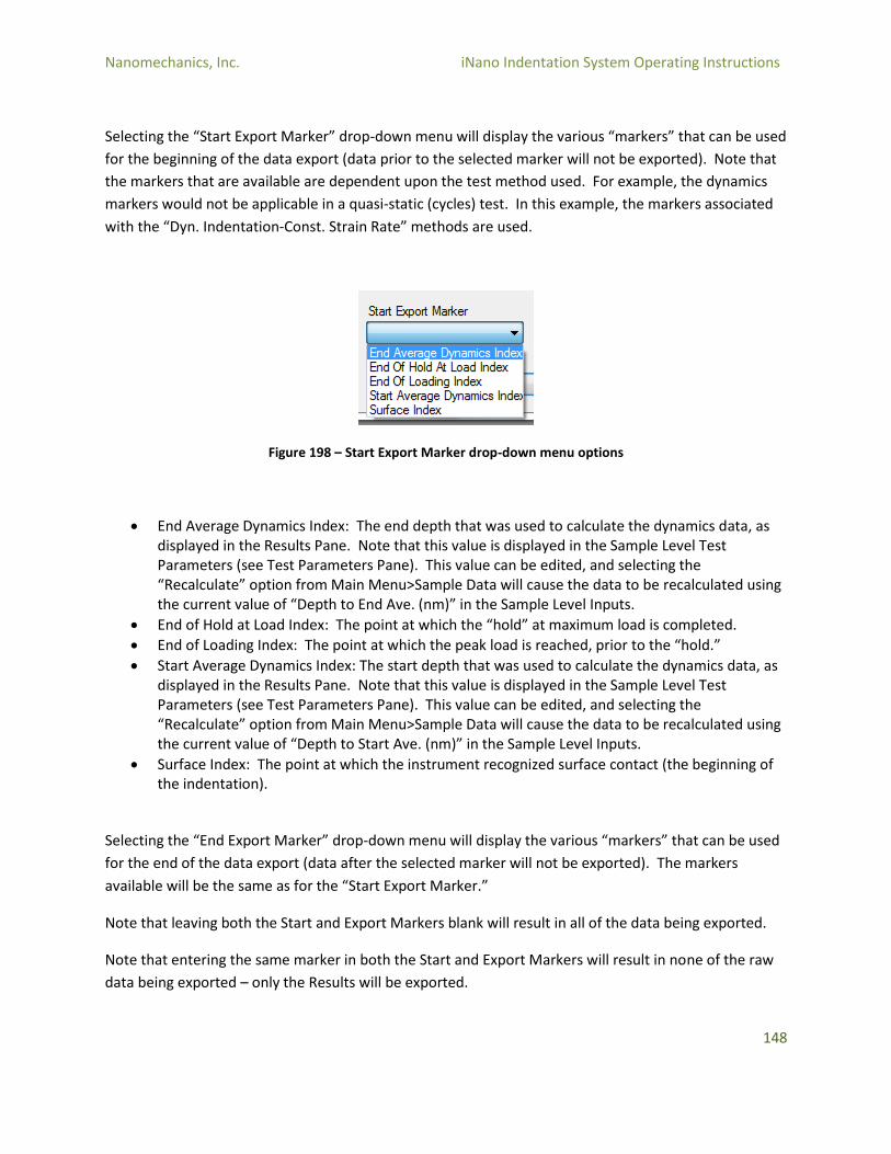
Nanomechanics, Inc. iNano Indentation System Operating Instructions
148
Selecting the “Start Export Marker” drop-down menu will display the various “markers” that can be used
for the beginning of the data export (data prior to the selected marker will not be exported). Note that
the markers that are available are dependent upon the test method used. For example, the dynamics
markers would not be applicable in a quasi-static (cycles) test. In this example, the markers associated
with the “Dyn. Indentation-Const. Strain Rate” methods are used.
Figure 198 – Start Export Marker drop-down menu options
End Average Dynamics Index: The end depth that was used to calculate the dynamics data, as displayed in the Results Pane. Note that this value is displayed in the Sample Level Test Parameters (see Test Parameters Pane). This value can be edited, and selecting the “Recalculate” option from Main Menu>Sample Data will cause the data to be recalculated using the current value of “Depth to End Ave. (nm)” in the Sample Level Inputs.
End of Hold at Load Index: The point at which the “hold” at maximum load is completed.
End of Loading Index: The point at which the peak load is reached, prior to the “hold.”
Start Average Dynamics Index: The start depth that was used to calculate the dynamics data, as displayed in the Results Pane. Note that this value is displayed in the Sample Level Test Parameters (see Test Parameters Pane). This value can be edited, and selecting the “Recalculate” option from Main Menu>Sample Data will cause the data to be recalculated using the current value of “Depth to Start Ave. (nm)” in the Sample Level Inputs.
Surface Index: The point at which the instrument recognized surface contact (the beginning of the indentation).
Selecting the “End Export Marker” drop-down menu will display the various “markers” that can be used
for the end of the data export (data after the selected marker will not be exported). The markers
available will be the same as for the “Start Export Marker.”
Note that leaving both the Start and Export Markers blank will result in all of the data being exported.
Note that entering the same marker in both the Start and Export Markers will result in none of the raw
data being exported – only the Results will be exported.
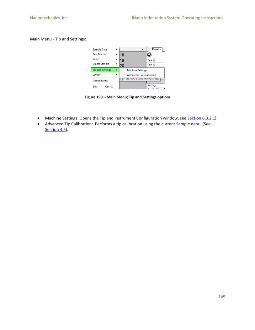
Nanomechanics, Inc. iNano Indentation System Operating Instructions
149
Main Menu - Tip and Settings:
Figure 199 – Main Menu; Tip and Settings options
Machine Settings: Opens the Tip and Instrument Configuration window, see Section 6.3.2.1).
Advanced Tip Calibration: Performs a tip calibration using the current Sample data. (See Section 4.5).
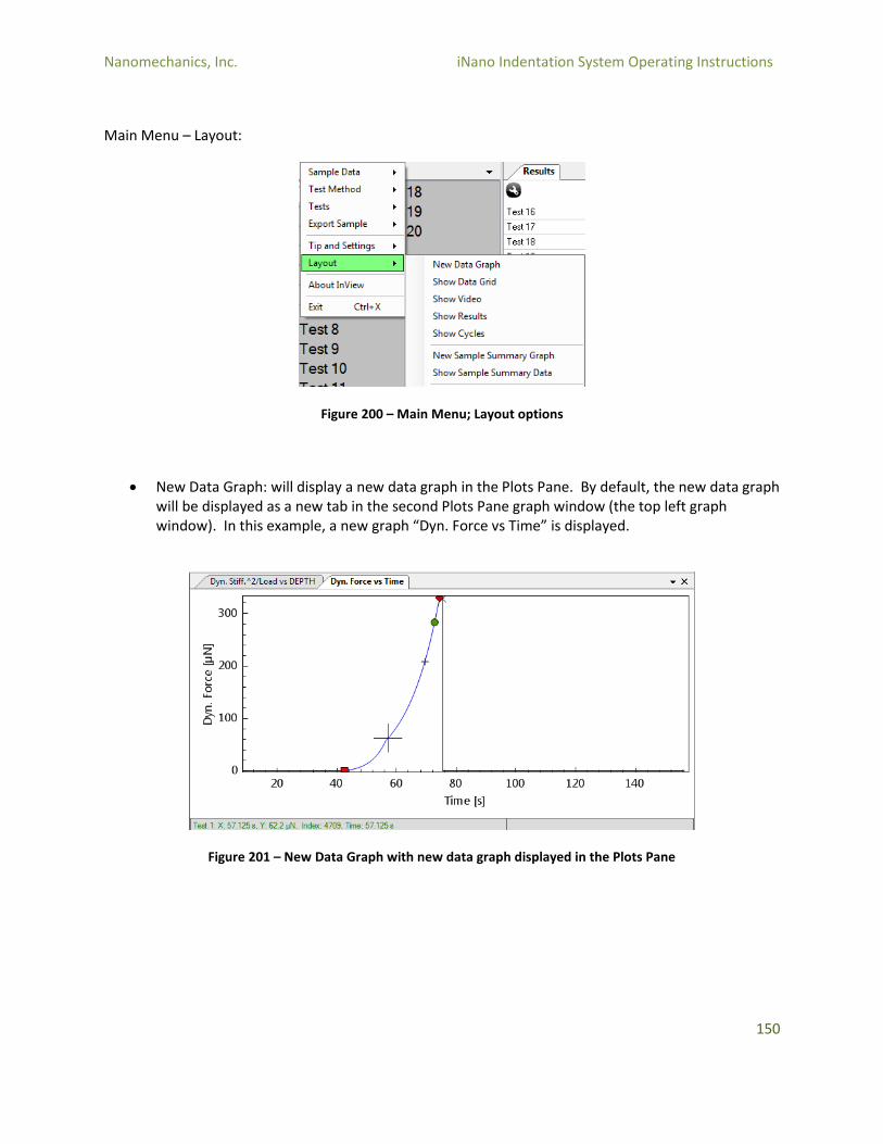
Nanomechanics, Inc. iNano Indentation System Operating Instructions
150
Main Menu – Layout:
Figure 200 – Main Menu; Layout options
New Data Graph: will display a new data graph in the Plots Pane. By default, the new data graph will be displayed as a new tab in the second Plots Pane graph window (the top left graph window). In this example, a new graph “Dyn. Force vs Time” is displayed.
Figure 201 – New Data Graph with new data graph displayed in the Plots Pane
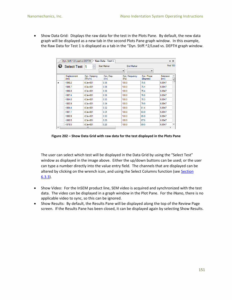
Nanomechanics, Inc. iNano Indentation System Operating Instructions
151
Show Data Grid: Displays the raw data for the test in the Plots Pane. By default, the new data graph will be displayed as a new tab in the second Plots Pane graph window. In this example, the Raw Data for Test 1 is displayed as a tab in the “Dyn. Stiff.^2/Load vs. DEPTH graph window.
Figure 202 – Show Data Grid with raw data for the test displayed in the Plots Pane
The user can select which test will be displayed in the Data Grid by using the “Select Test”
window as displayed in the image above. Either the up/down buttons can be used; or the user
can type a number directly into the value entry field. The channels that are displayed can be
altered by clicking on the wrench icon, and using the Select Columns function (see Section
6.3.3).
Show Video: For the InSEM product line, SEM video is acquired and synchronized with the test data. The video can be displayed in a graph window in the Plot Pane. For the iNano, there is no applicable video to sync, so this can be ignored.
Show Results: By default, the Results Pane will be displayed along the top of the Review Page screen. If the Results Pane has been closed, it can be displayed again by selecting Show Results.
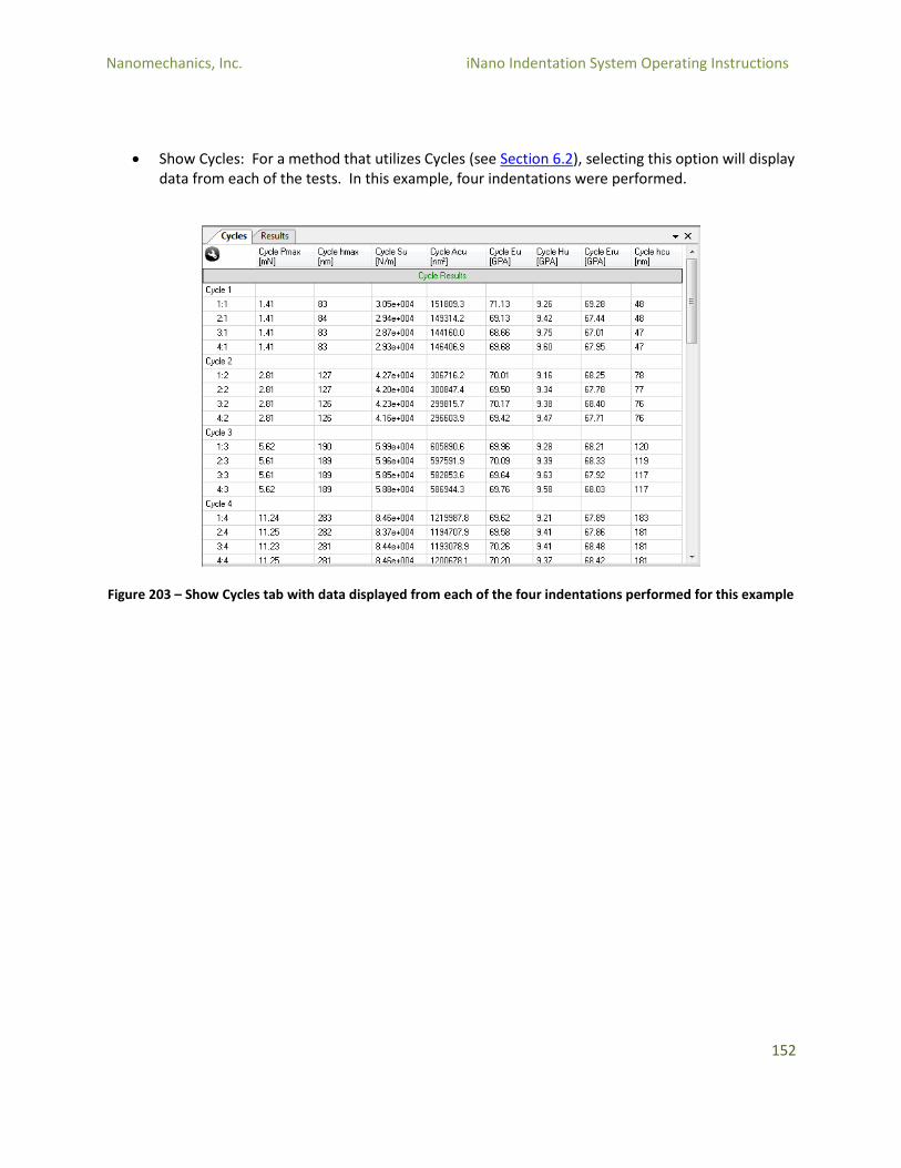
Nanomechanics, Inc. iNano Indentation System Operating Instructions
152
Show Cycles: For a method that utilizes Cycles (see Section 6.2), selecting this option will display data from each of the tests. In this example, four indentations were performed.
Figure 203 – Show Cycles tab with data displayed from each of the four indentations performed for this example
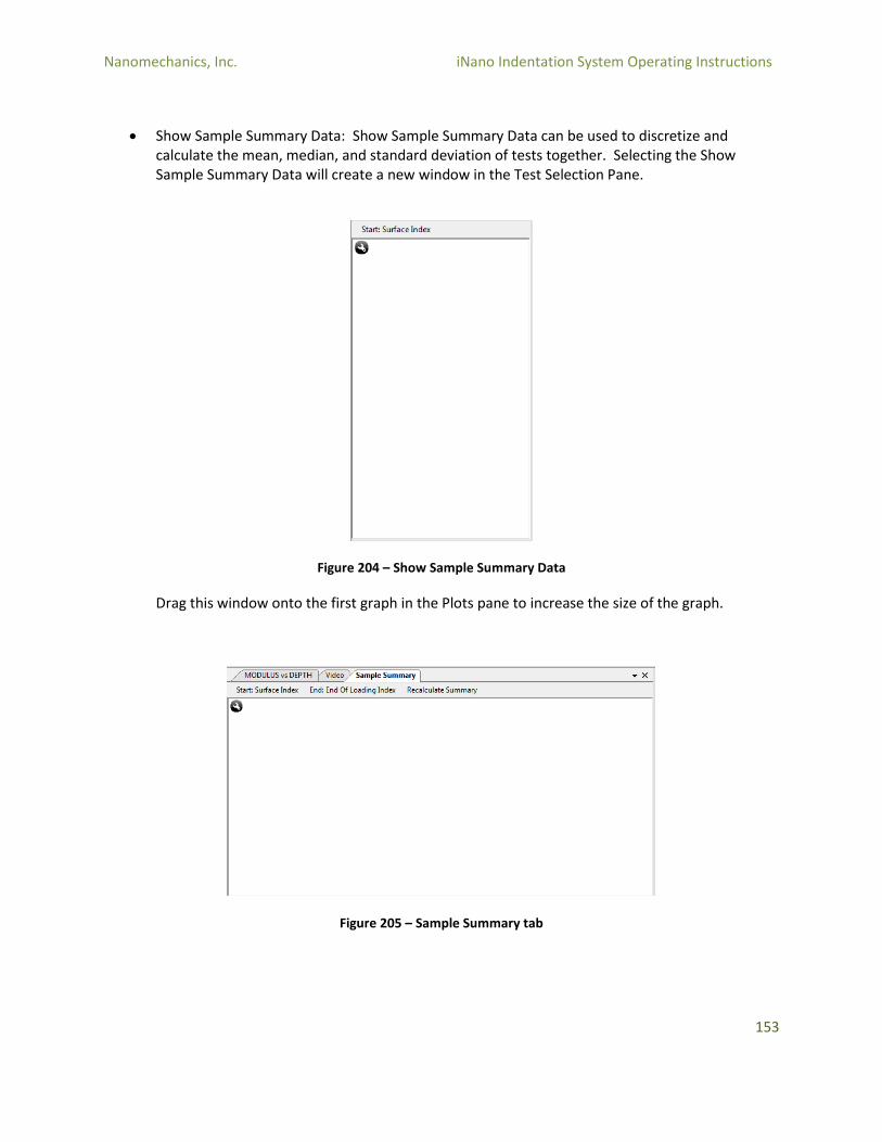
Nanomechanics, Inc. iNano Indentation System Operating Instructions
153
Show Sample Summary Data: Show Sample Summary Data can be used to discretize and calculate the mean, median, and standard deviation of tests together. Selecting the Show Sample Summary Data will create a new window in the Test Selection Pane.
Figure 204 – Show Sample Summary Data
Drag this window onto the first graph in the Plots pane to increase the size of the graph.
Figure 205 – Sample Summary tab
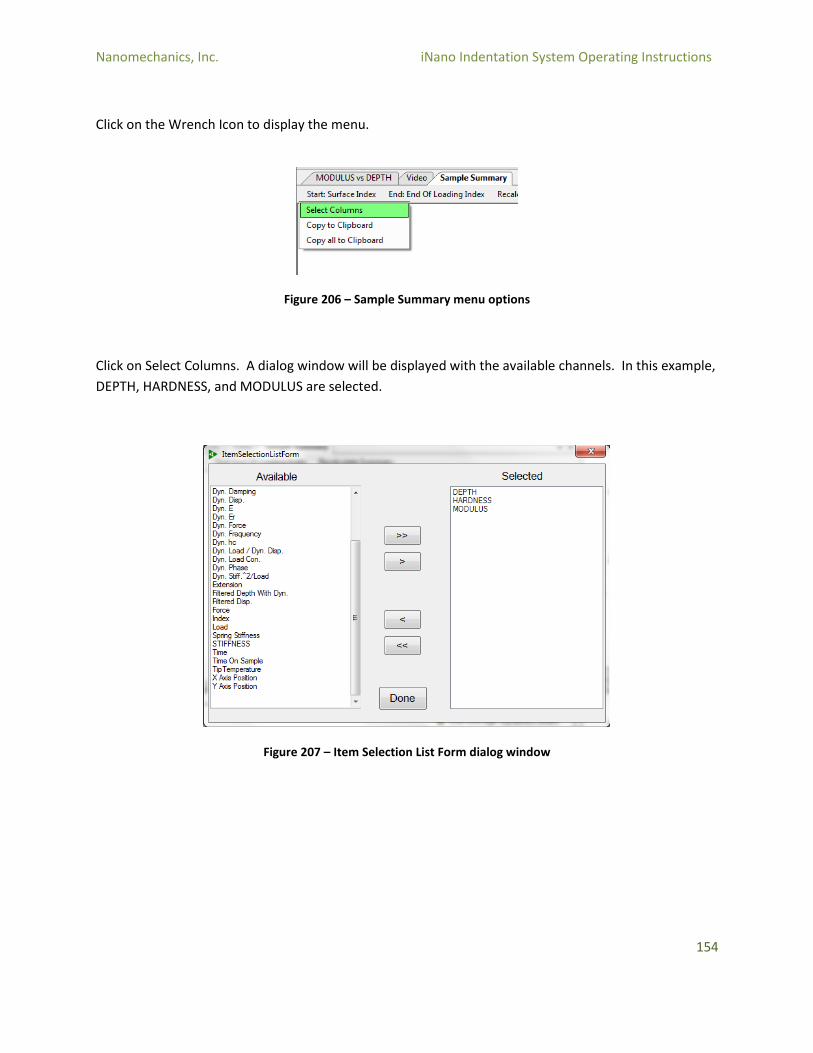
Nanomechanics, Inc. iNano Indentation System Operating Instructions
154
Click on the Wrench Icon to display the menu.
Figure 206 – Sample Summary menu options
Click on Select Columns. A dialog window will be displayed with the available channels. In this example,
DEPTH, HARDNESS, and MODULUS are selected.
Figure 207 – Item Selection List Form dialog window
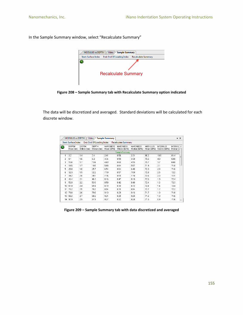
Nanomechanics, Inc. iNano Indentation System Operating Instructions
155
In the Sample Summary window, select “Recalculate Summary”
Figure 208 – Sample Summary tab with Recalculate Summary option indicated
The data will be discretized and averaged. Standard deviations will be calculated for each
discrete window.
Figure 209 – Sample Summary tab with data discretized and averaged
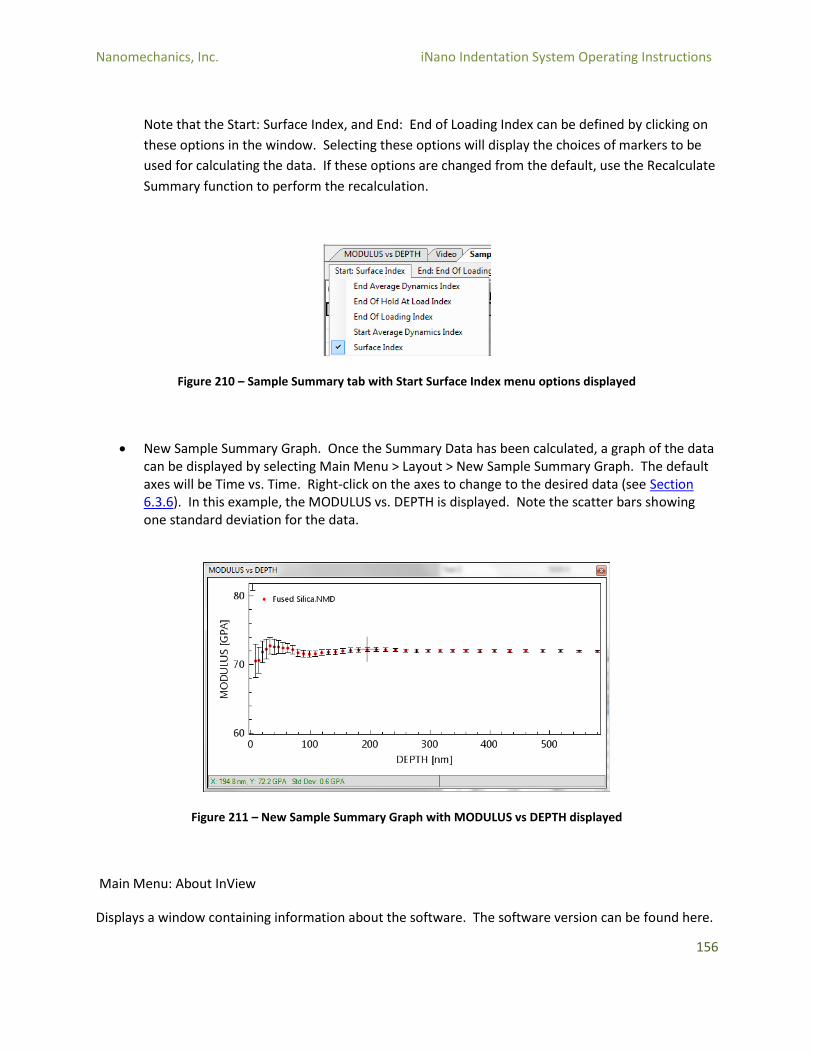
Nanomechanics, Inc. iNano Indentation System Operating Instructions
156
Note that the Start: Surface Index, and End: End of Loading Index can be defined by clicking on
these options in the window. Selecting these options will display the choices of markers to be
used for calculating the data. If these options are changed from the default, use the Recalculate
Summary function to perform the recalculation.
Figure 210 – Sample Summary tab with Start Surface Index menu options displayed
New Sample Summary Graph. Once the Summary Data has been calculated, a graph of the data can be displayed by selecting Main Menu > Layout > New Sample Summary Graph. The default axes will be Time vs. Time. Right-click on the axes to change to the desired data (see Section 6.3.6). In this example, the MODULUS vs. DEPTH is displayed. Note the scatter bars showing one standard deviation for the data.
Figure 211 – New Sample Summary Graph with MODULUS vs DEPTH displayed
Main Menu: About InView
Displays a window containing information about the software. The software version can be found here.
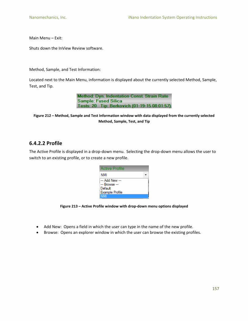
Nanomechanics, Inc. iNano Indentation System Operating Instructions
157
Main Menu – Exit:
Shuts down the InView Review software.
Method, Sample, and Test Information:
Located next to the Main Menu, information is displayed about the currently selected Method, Sample,
Test, and Tip.
Figure 212 – Method, Sample and Test Information window with data displayed from the currently selected
Method, Sample, Test, and Tip
6.4.2.2 Profile
The Active Profile is displayed in a drop-down menu. Selecting the drop-down menu allows the user to
switch to an existing profile, or to create a new profile.
Figure 213 – Active Profile window with drop-down menu options displayed
Add New: Opens a field in which the user can type in the name of the new profile.
Browse: Opens an explorer window in which the user can browse the existing profiles.
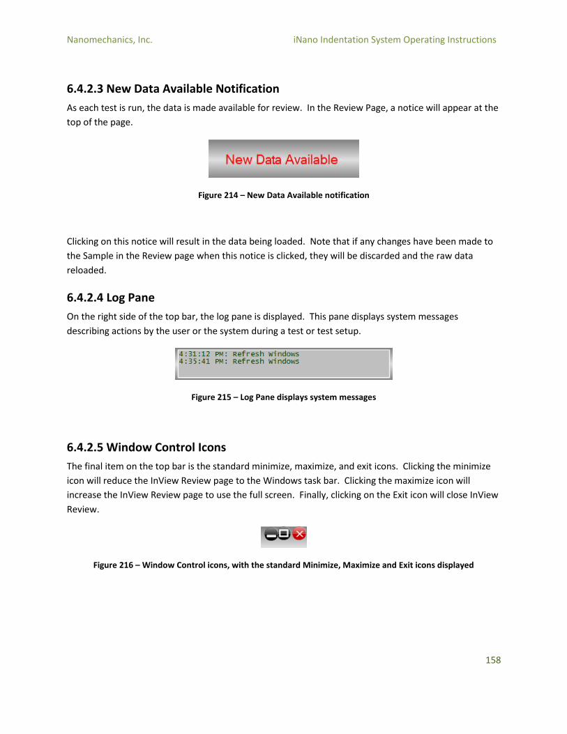
Nanomechanics, Inc. iNano Indentation System Operating Instructions
158
6.4.2.3 New Data Available Notification
As each test is run, the data is made available for review. In the Review Page, a notice will appear at the
top of the page.
Figure 214 – New Data Available notification
Clicking on this notice will result in the data being loaded. Note that if any changes have been made to
the Sample in the Review page when this notice is clicked, they will be discarded and the raw data
reloaded.
6.4.2.4 Log Pane
On the right side of the top bar, the log pane is displayed. This pane displays system messages
describing actions by the user or the system during a test or test setup.
Figure 215 – Log Pane displays system messages
6.4.2.5 Window Control Icons
The final item on the top bar is the standard minimize, maximize, and exit icons. Clicking the minimize
icon will reduce the InView Review page to the Windows task bar. Clicking the maximize icon will
increase the InView Review page to use the full screen. Finally, clicking on the Exit icon will close InView
Review.
Figure 216 – Window Control icons, with the standard Minimize, Maximize and Exit icons displayed
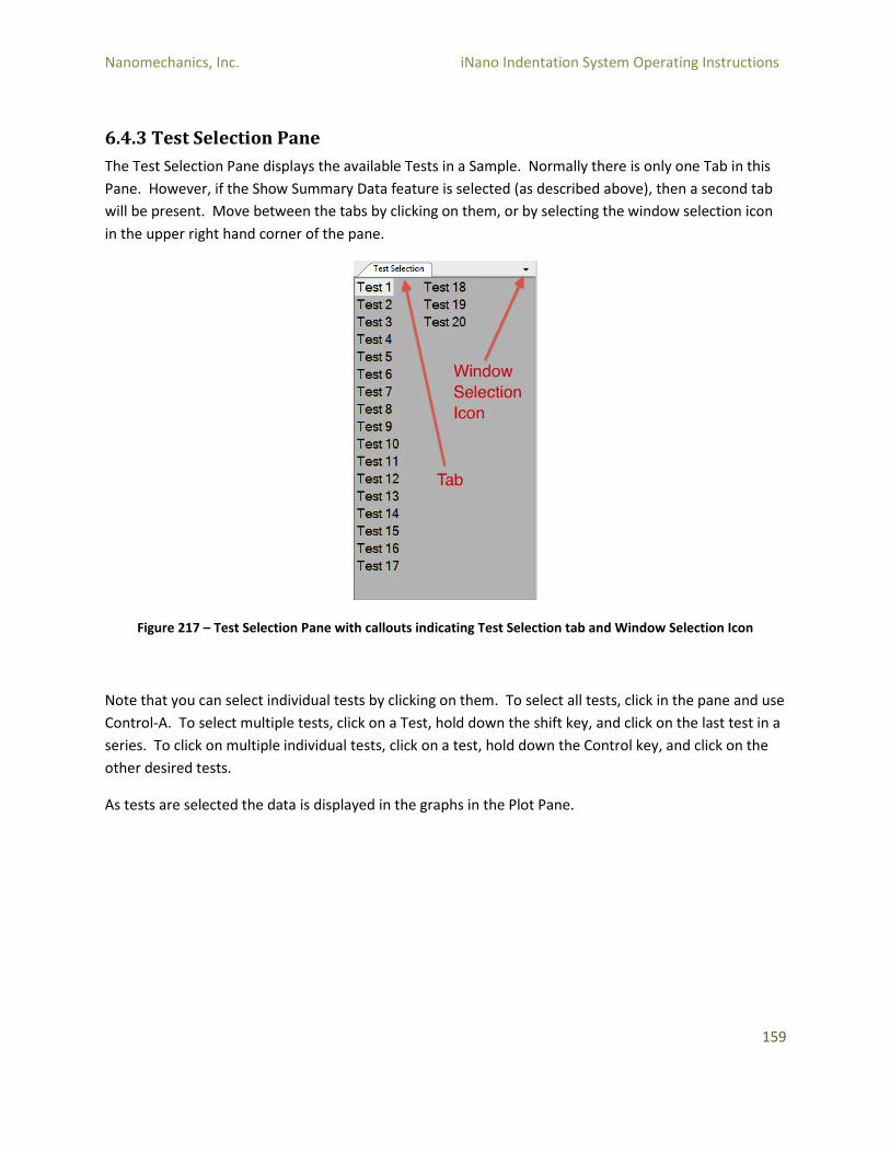
Nanomechanics, Inc. iNano Indentation System Operating Instructions
159
6.4.3 Test Selection Pane
The Test Selection Pane displays the available Tests in a Sample. Normally there is only one Tab in this
Pane. However, if the Show Summary Data feature is selected (as described above), then a second tab
will be present. Move between the tabs by clicking on them, or by selecting the window selection icon
in the upper right hand corner of the pane.
Figure 217 – Test Selection Pane with callouts indicating Test Selection tab and Window Selection Icon
Note that you can select individual tests by clicking on them. To select all tests, click in the pane and use
Control-A. To select multiple tests, click on a Test, hold down the shift key, and click on the last test in a
series. To click on multiple individual tests, click on a test, hold down the Control key, and click on the
other desired tests.
As tests are selected the data is displayed in the graphs in the Plot Pane.

Nanomechanics, Inc. iNano Indentation System Operating Instructions
160
6.4.4 Test Parameters Pane
The Test Parameters Pane displays the Sample Level and Test Level editable post-test inputs for a given
Sample. Note that these may change depending on the Method used. In the example below, it is
possible for the user to change the Poisson’s Ratio, whether or not to apply the Drift Correction, and the
Start and End Depths used for averaging the hardness, modulus, and other dynamic channels.
Figure 218 – Test Parameters Pane displaying Sample Level and Test Level fields
Note that any changes made in this pane will not be applied until the Sample is recalculated (see Section
6.4.2.1).
6.4.5 Results Pane
The Results Pane shows data for each test. The channels available will depend on the Sample and
Method used. Scrolling to the bottom of the Results Pane will display summaries for each column,
including the average, standard deviation, and coefficient of variation.
Figure 219 – Results Pane showing data for each test
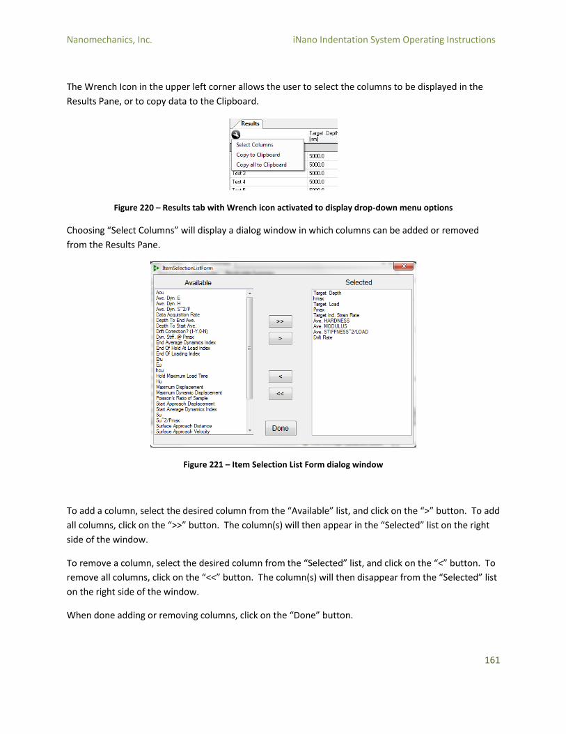
Nanomechanics, Inc. iNano Indentation System Operating Instructions
161
The Wrench Icon in the upper left corner allows the user to select the columns to be displayed in the
Results Pane, or to copy data to the Clipboard.
Figure 220 – Results tab with Wrench icon activated to display drop-down menu options
Choosing “Select Columns” will display a dialog window in which columns can be added or removed
from the Results Pane.
Figure 221 – Item Selection List Form dialog window
To add a column, select the desired column from the “Available” list, and click on the “>” button. To add
all columns, click on the “>>” button. The column(s) will then appear in the “Selected” list on the right
side of the window.
To remove a column, select the desired column from the “Selected” list, and click on the “<” button. To
remove all columns, click on the “<<” button. The column(s) will then disappear from the “Selected” list
on the right side of the window.
When done adding or removing columns, click on the “Done” button.
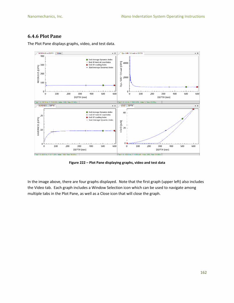
Nanomechanics, Inc. iNano Indentation System Operating Instructions
162
6.4.6 Plot Pane
The Plot Pane displays graphs, video, and test data.
Figure 222 – Plot Pane displaying graphs, video and test data
In the image above, there are four graphs displayed. Note that the first graph (upper left) also includes
the Video tab. Each graph includes a Window Selection icon which can be used to navigate among
multiple tabs in the Plot Pane, as well as a Close icon that will close the graph.
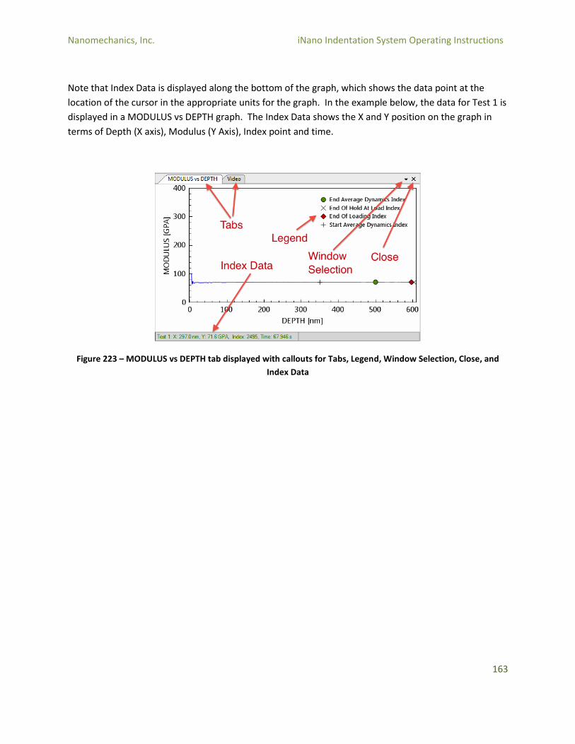
Nanomechanics, Inc. iNano Indentation System Operating Instructions
163
Note that Index Data is displayed along the bottom of the graph, which shows the data point at the
location of the cursor in the appropriate units for the graph. In the example below, the data for Test 1 is
displayed in a MODULUS vs DEPTH graph. The Index Data shows the X and Y position on the graph in
terms of Depth (X axis), Modulus (Y Axis), Index point and time.
Figure 223 – MODULUS vs DEPTH tab displayed with callouts for Tabs, Legend, Window Selection, Close, and
Index Data
Nanomechanics, Inc. iNano Indentation System Operating Instructions
164
The axes can be modified by right-clicking on the axis title or the axis units.
Figure 224 – Right-clicking on the Axis Title will display the above dialog window with options to modify axes
Y Axis Channel will display a list of the available Channels.
Y Axis Units will display the units that are available for a specific Channel.
Auto Scale Max and Min: When the checkbox by the Auto Scale is selected, the graph will automatically be rescaled as necessary to display the available data. When the checkbox is unchecked, the maximum or minimum scale of the axis will be set to the value entered in the value entry field. Note that the units are contextual (i.e., Displacement will be displayed as the selected Axis Unit, such as nm or mm, etc.).
Font: The Font size can be increased or decreased as desired.
Grid: The user can choose whether or not to show the Major and Minor gridlines on the graph.
Right-clicking on the graph itself will display another menu that can be used to control how the graph is
displayed.
Figure 225 – Right-clicking on the graph will display another menu with graph control display options
Nanomechanics, Inc. iNano Indentation System Operating Instructions
165
Show Legend: Show Legend allows the user to control how (or if) the legend is displayed on the graph.
Figure 226 – Show Legend menu options
o Selecting Tests will display the test number o Selecting Markers will display the markers and marker title. o Selecting Tests AND Markers will display both o Selecting None will remove the legend. o Position Left places the legend at the left side of the graph. o Position Right places the legend at the right side of the graph. o Position Far Right places the legend outside the body of the graph
Show Title: Displays the Sample Name at the top of the graph.
Show Lines: Displays lines between each data point on the graph (displays a “curve”).
Show Data Points: Displays the individual data points on the graph.
Show Tracker: Displays crosshairs at the cursor location (and the corresponding Index data at the bottom of the graph).
Set Marker: This function enables the user to manually place a marker at the current location of the cross hairs. For example, the Surface Marker can be moved by this functionality. Note that this is method-specific. If a Marker is moved, used Recalculate to apply changes. Note that Set Marker can only be used when a single test is selected.
Copy to Clipboard: Creates a copy of the graph on the clipboard so that it can be pasted into another document.
Export: Export allows the graph to be saved as either a SVG or PNG file. Selecting this option will cause a dialog window to be displayed in which the user can select the filename and location to save the image file.
Line Width: This option allows the user to change line width on the line or “curve.” There are three options: Thin, Normal, or Thick.
Nanomechanics, Inc. iNano Indentation System Operating Instructions
166
As noted in previous descriptions, new graphs can be added to the Plot Pane. Main Menu > Layout >
New Data Graph will display a new data graph in the Plots Pane. By default, the new data graph will be
displayed as a new tab in the second Plots Pane graph window. In this example, a new graph “Dyn.
Force vs Time” is displayed.
Figure 227 – Example of new graphs added to the Plot Pane
The graphs can be repositioned as desired. Clicking on the tab with the graph name (in this example,
Dyn Force vs Time) and dragging the graph into a “free area” of the Plot Pane will cause the graph to
become a free-floating window.
Figure 228 – Example of free-floating window
Nanomechanics, Inc. iNano Indentation System Operating Instructions
167
Note that while the graph is being dragged from one location to another, the graph placement function
will appear over the “dominant” pane in the Plot Pane.
Figure 229 – Example of the graph placement function/directional buttons icon
The dominant pane is the pane in which the actions of the graph placement function will take place. In
the example below, the MODULUS vs. DEPTH graph is the “Active Graph” in that it is being dragged to a
new location. The Shaded Area shows where the graph will be placed. The Graph Placement function
appears over the Dyn.Stiff.^2/Load vs. DEPTH graph, as the cursor is located over this graph.
Figure 230 – Example of dominant pane placement with callouts for Dominant Graph, Graph Placement, Active
Graph, and Shaded Area
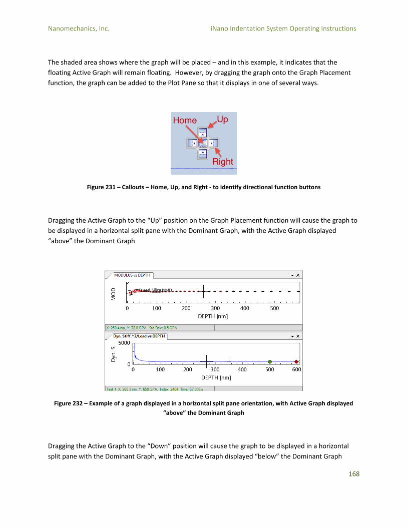
Nanomechanics, Inc. iNano Indentation System Operating Instructions
168
The shaded area shows where the graph will be placed – and in this example, it indicates that the
floating Active Graph will remain floating. However, by dragging the graph onto the Graph Placement
function, the graph can be added to the Plot Pane so that it displays in one of several ways.
Figure 231 – Callouts – Home, Up, and Right - to identify directional function buttons
Dragging the Active Graph to the “Up” position on the Graph Placement function will cause the graph to
be displayed in a horizontal split pane with the Dominant Graph, with the Active Graph displayed
“above” the Dominant Graph
Figure 232 – Example of a graph displayed in a horizontal split pane orientation, with Active Graph displayed
“above” the Dominant Graph
Dragging the Active Graph to the “Down” position will cause the graph to be displayed in a horizontal
split pane with the Dominant Graph, with the Active Graph displayed “below” the Dominant Graph
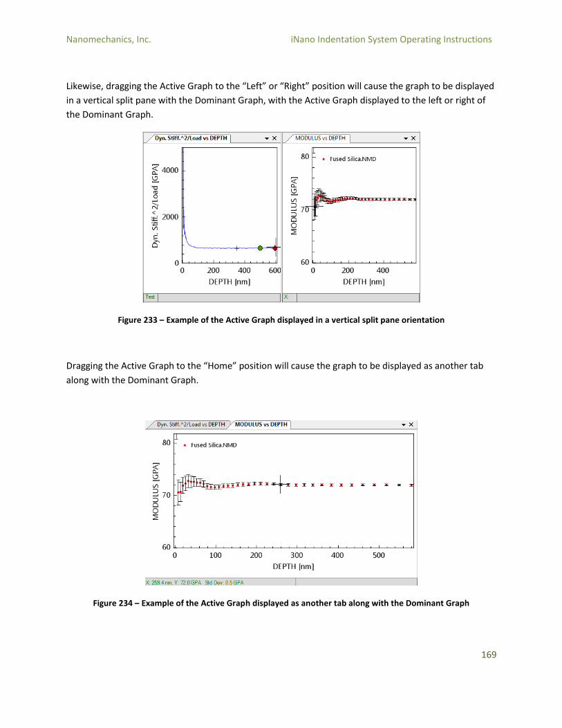
Nanomechanics, Inc. iNano Indentation System Operating Instructions
169
Likewise, dragging the Active Graph to the “Left” or “Right” position will cause the graph to be displayed
in a vertical split pane with the Dominant Graph, with the Active Graph displayed to the left or right of
the Dominant Graph.
Figure 233 – Example of the Active Graph displayed in a vertical split pane orientation
Dragging the Active Graph to the “Home” position will cause the graph to be displayed as another tab
along with the Dominant Graph.
Figure 234 – Example of the Active Graph displayed as another tab along with the Dominant Graph

Nanomechanics, Inc. iNano Indentation System Operating Instructions
170
6.5 References
6.5.1 Channels
There are a number of Channels defined in the InView software. The following list describes most of the
channels:
Extension: The position of the extension system relative to the last point at which it was zeroed.
Force: The fore being generated by the coil and magnet. It is calibrated as a function of current
to the coil. It has a range of +/- 50mN. Zero is zero current through the coil and positive values
try to extend the probe.
Displacement: The displacement from the center of travel as measured by the capacitive
sensor. It is calibrated as a function of “DisplacementVolts” from the sensor. It has a value of
approximately +/- 25µm travel. Zero is in the center of motion and the positive direction is
extending the probe.
LOAD: The LOAD represents the load applied on the specimen for both dynamic and
nondynamic portions of the experiment.
DEPTH: The DEPTH represents the penetration into the sample for both dynamic and
nondynamic portions of the experiment.
STIFFNESS: The STIFFNESS represents the contact stiffness corrected for the load frame
compliance for both dynamic and nondynamic portions of the experiment.
HARDNESS: The HARDNESS final result for this experiment.
MODULUS: The modulus calculated from dynamics and the Oliver and Pharr method.
Tip Temperature: The temperature of the tip.
Dyn. Damping: The measured contact damping during a dynamic experiment. Dyn. Disp.: The RMS value of the “Displacement” at the “Target Frequency.” Dyn Force: The RMS value of the “Force” at the “Target Frequency.” Dyn. Frequency: The frequency at which dynamic measurements are made. Dyn. Phase: The phase angle between the “Dyn. Disp.” and the “Dyn.Force.” Dyn. Stiffness: The stiffness being measured by the dynamic system. It is calculated using the calibrated system spring constant, damping, and mass.

Nanomechanics, Inc. iNano Indentation System Operating Instructions
171
Spring Stiffness: The stiffness of the support springs. It is calibrated as a function of “Displacement.”
Time: Time is measured from the start of the test.
X Axis Position: The position of the X axis manipulator.
Y Axis Position: The position of the Y axis manipulator.
(dP/dt)/P: The time derivative of the Load divided by the Load at each point in time. If Hardness and Modulus are constant and this parameter is constant, the indentation strain rate should be constant.
Auto Derivatives Tc: The time constant used to calculate the derivatives. It is set such that the “Delta Disp. In Der.” is satisfied.
Auto Points In Derivative: The number of data points in the buffers used to measure the
derivatives. In this case the number is set such that there is at least “Delta Disp. In Der.”
displacement change in the buffer. There is a maximum set by the system.
Cor. Dyn. Stiffness: The stiffness from dynamics corrected for the load frame stiffness.
d(Disp)/d(Time): The slope of the “Displacement” versus “Time” curve.
d(Force)/d(Disp): The slope of the “Force” versus “Displacement” curve.
d(Force)/d(Time): The slope of the “Force” versus “Time” curve.
Depth: The depth of the indentation. It is the zeroed value of the “Displacement” corrected for
load frame stiffness and drift rate. It is zero prior to surface detection.
Dyn. H: The hardness calculated from the dynamics and the Oliver and Pharr method.
Dyn. Ac: The contact area calculated from the dynamics and the Oliver and Pharr method, as
well as the current tip area calibration.
Dyn. E: The modulus calculated from the dynamics and the Oliver and Pharr method.
Dyn. Er: The reduced modulus calculated from the dynamics and the Oliver and Pharr method.
Dyn. hc: The contact depth calculated from the dynamics and the Oliver and Pharr method.
Dyn. Load / Dyn. Disp: This parameter should be equal to spring stiffness at low frequencies.

Nanomechanics, Inc. iNano Indentation System Operating Instructions
172
Dyn. Load Con.: This is the control loop that is modifying “Dyn.Force.” At small loads the result
is a fraction of the applied “Load.” At larger loads the result tries to achieve a constant
“Dyn.Disp.”
Dyn. Load Req.: This value is used to control “Dyn.Force” to obtain a constant value of
“Dyn.Disp.”
Dyn. Stiff.^2/Load: The Stiffness^2/Load is a parameter that should be insensitive to the area
function. It can be used to determine load frame stiffness.
Filtered Depth With Dyn.: The depth of the indentation when dynamics are in use. It is the
zeroed value of the “Filtered Disp.” Corrected for load frame stiffness, drift rate, and the
“Dyn.Disp.” It is zero prior to surface detection.
Filtered Disp.: The “Displacement” filtered to remove the “Dyn.Disp.” The “Displacement” is
averaged over “Points In Depth” which represents an integer number of waves, “Waves to Filter
Dynamics.”
Index: The index of a point in the data array.
Load: The “Load” applied to the sample. It is the zeroed value of the “Force” corrected for spring deflection. It is zero prior to surface detection. Dynamics are not considered.
Load With Dynamics: The load applied to the sample. It is the zeroed value of the “Force” corrected for spring deflection and the “Dyn.Load.” It is zero prior to surface detection.
Loading Rate Req.: The loading rate required to achieve a constant value of loading rate/”Load.” The “Approach Loading Rate” is assumed to be small and is added in to achieve a smooth transition.
Surface Trigger Counter: The surface is detected when “d(Force)/d(Disp)” exceeds the “Surface Stiffness Trigger” + Spring Constant. This must occur “Surface Trigger Required” number of times sequentially. “Surface Trigger Counter” tracks this number.
Time On Sample: The “Time” that has passed since the “Surface Index” was assigned.