Embed Size (px)
Citation preview

Quick Start
InView Marquee Message Display
Catalog Number 2706
About This Publication This publication provides steps for configuring an InView display to display messages.
Configure the InView Display for Serial Download
Follow these steps to configure the display for serial download.
What You Need
You need these items to complete this task:
• Catalog number 2706-P22R, 2706-P4x, 2706-P7x, or 2706-P9x
• Catalog number 2706-PCABLE1, Series A
• Catalog number 2706-PSW1 (InView Message software)
• 24V DC, Class 2, SELV Power Supply (for catalog number 2706-P22R only)
• InView User Manual, publication 2706-UM016
• InView Installation Instructions, publication 2706-IN006
• Communication Module Installation Instructions, publication 2706-IN015
• Communication Module User Manual, publication 2706-UM017
Topic Page
About This Publication 1
Configure the InView Display for Serial Download
1
Configure an EtherNet/IP Communication Module
10
Configure a TCP/IP Communication Module 18
Troubleshooting 22
Additional Resources 22

2 InView Marquee Message Display
Equipment Setup
Connect a power cord or power supply and catalog number 2706-PCABLE1, series A, to the InView display and to COM1 of the computer.
Configure the Display
Follow these steps to configure the display.
1. Install the InView Messaging software.
Refer to the installation instructions included on the CD.
2. Launch the InView Software from Start > Programs > Rockwell Automation > InView Software > InView Messaging Software.
3. After opening the software, click Create New InView Project and click OK.
TIP Verify RSLinx software is not using the serial port.
Publication 2706-QS001D-EN-P - January 2009

InView Marquee Message Display 3
4. In the Project Name field, type an appropriate name for your project and click OK.
You can also write an optional description of the project if you choose.
5. In the Add Display dialog box, type a display name and then choose your InView display type.
6. Click Next to continue.
TIP You can add up to 100 displays to your project in the Add Display dialog box by changing the Number Required. Displays can also be added individually from the main screen by right-clicking the project folder on the top left side.
Publication 2706-QS001D-EN-P - January 2009

4 InView Marquee Message Display
Configure Serial Communication
Follow these steps to configure serial communication.
1. In the Add Display dialog box, click Serial for the Download Protocol.
Once you have selected it, the Serial port settings heading becomes bold.
2. Unless otherwise required for your application, accept the default Serial port settings.
3. After you have finished setting up the Serial port settings, click Finish.
Create Messages
Next you will be directed to the message editor, where you can create your messages. The background message is the message that first appears when you power up the InView display. The default background message is Rockwell Automation.
Follow these steps to create messages.
1. You can modify the background message by clicking the row that contains the ID# B and then clicking the message editing field.
Publication 2706-QS001D-EN-P - January 2009

InView Marquee Message Display 5
The background message is always displayed on your InView Message Display when you cycle power and no messages are being triggered.
2. To create a new message, click the down arrow icon until a new row is added to the message list with the next available ID
number.
The message is created with the defaults of the previous message.
TIP For a full description of all of the icons on the Message Editor, see Help topic Working with Messages, subtopic Message Attributes.
Publication 2706-QS001D-EN-P - January 2009

6 InView Marquee Message Display
3. Create a sample message.
a. Click the new message row.
b. Click the message editing field.
c. Type ’New Message’.
Publication 2706-QS001D-EN-P - January 2009

InView Marquee Message Display 7
Download to the InView Display
Follow these steps to download a message to the display.
1. On the main screen, from the Message File menu, choose Download Message File.
A dialog box appears that shows all of the displays in the project that are of the same type as the display you selected.
You can download to multiple displays at the same time by selecting the displays that you want to download in this dialog box. You need to use the RS485 protocol to download to multiple displays.
2. After you have selected the displays that you want to download to, click Download.
A new dialog box opens, showing the download progress. If there is a communication error, it is displayed here. During download, the progress is indicated in the status field.
Publication 2706-QS001D-EN-P - January 2009

8 InView Marquee Message Display
Refer to Troubleshooting on page 22 for a list of possible causes of errors.
3. Once the download completes, click Exit.
Verify that your InView Display shows the default background message of Rockwell Automation.
By default when doing a download or cycling power, the InView Message Display will always show the background message. Any other messages that were also downloaded are stored in memory until that message number is triggered.
Download Individual Messages
You can download and view a specific message in the file by right-clicking the message and choosing Trigger Message.
Publication 2706-QS001D-EN-P - January 2009

InView Marquee Message Display 9
Follow these steps to download individual messages.
1. Select your Message File.
2. Right-click the message you want to trigger and choose Trigger Message.
3. Select the display you want to download to and click Download.
Once it completes the download, your InView Message Display now displays the message you just triggered.
Publication 2706-QS001D-EN-P - January 2009

10 InView Marquee Message Display
Configure an EtherNet/IP Communication Module
Follow these steps to configure an EtherNet/IP communication module.
What You Need
This list indicates what you need to complete this task:
• Catalog numbers 2706-P22R, 2706-P4x, 2706-P7x, 2706-P9x
• Catalog numbers 2706-PENETP, 2706-PENETM, 2706-PENETK InView Ethernet modules
• Ethernet cable (user supplied)
• RS-232 serial cable (supplied with Ethernet module)
• RSLinx software
• InView User Manual, publication 2706-UM016
• InView Installation Instructions, publication 2706-IN006
• Communication Module Installation Instructions, publication 2706-IN015
• Communication Module User Manual, publication 2706-UM017
Equipment Setup
Follow these instructions to configure the communication module for a 2706-P22R display.
• Connect a Class 2, 24V DC power supply.
• Connect the RS-232 (catalog number 2711-NC13) cable to a personal computer.
TIP Use a 2706-PENETP module for a 2706-P22R display, a 2706-PENETM module for a 2706-P4x display, and a 2706-PENETK module for a 2706-P7x or 2706-P9x display.
1 2 3 4 5
6 7 8 9
RS-2322711-NC13 Cable Supplied
Network Communication Power
Power
Publication 2706-QS001D-EN-P - January 2009

InView Marquee Message Display 11
Follow these instructions to setup the communication module for a 2706-P4x, 2706-P7x, or 2706-P9x display.
• Connect the power cord.
• Disconnect the DB9 connector inside the communication module.
• Connect your RS-232 (catalog number 2711-NC13 or equivalent) cable to a personal computer and the communication module.
Network Communication
Cable Provided with Module
To Personal Computer(catalog number 2711-NC13 or equivalent)
Disconnect communication module internal DB9 connector, connect your cable.
BlackRedOrangeBrown
Cable Provided with Module
Publication 2706-QS001D-EN-P - January 2009

12 InView Marquee Message Display
Configure Communication
Follow these steps to configure the communication.
From an existing project, start at the main page of the InView Messaging software.
1. Right-click the display you wish to modify and choose Edit Display.
2. In the Edit Display dialog box, click the Communications tab and choose Industrial Network Comms as your Download Protocol.
3. At the bottom of the dialog box, in the Industrial Network Communications settings, click Configure Communications.
Publication 2706-QS001D-EN-P - January 2009

InView Marquee Message Display 13
4. In the InView Network Communications dialog box, choose EtherNet/IP as your communication protocol and click Next.
5. From the Node Type pull-down menu, choose your node, for example SLC 5/05.
6. In the Node Address field, type the controller’s node address.
7. Click Next.
Publication 2706-QS001D-EN-P - January 2009

14 InView Marquee Message Display
8. In the EtherNet/IP Configuration dialog box, uncheck both DHCP/BootP Enable and DNS Enable.
9. Enter the IP Address for your communication module and the required Subnet Mask and click Next.
10. In Tag Setup, configure your tags, as required by your application, then click Next.
TIP The node address of the controller and the IP address of the message display must be unique in the fourth entry, for example, 192.168.1.100 and 192.168.1.120. Leave the Gateway Address blank unless required for your application.
Publication 2706-QS001D-EN-P - January 2009

InView Marquee Message Display 15
11. In the dialog box that follows, save your project, then download it to the module.
Download the File Serially
If you want to download the file by using the serial port, in the Download File dialog box, accept the default Transfer Type, and click OK.
The Application Download dialog box opens. This dialog box shows your download progress. If there are any errors, they will be displayed here. Refer to the troubleshooting guide at the end of this document for a list of possible causes of errors. Once the download is complete, the module will restart. The EtherNet Communication Module can now be connected to the message display and is ready to communicate with the message display and the controller.
TIP The InView Message software CD contains demo applications for configuring the Tag Setup for various controller types and communication modules. These can be found at:
Rockwell Automation\InView Version 2\Demos\Advanced\SLC500
Rockwell Automation\InView Version 2\Demos\Advanced\InView
Publication 2706-QS001D-EN-P - January 2009

16 InView Marquee Message Display
Download the File by Using Your EtherNet Driver
Follow these steps to download a file by using an EtherNet driver.
1. On the Download File dialog box, from the Transfer Type pull-down menu, choose RSLinx Network and click Setup.
The RSLinx configuration dialog box opens.
2. In the Configure Drivers dialog box, from the Available Driver Type pull-down menu, choose Ethernet devices, and click Add New.
Another dialog box opens, prompting you to give the new driver a name.
3. Name the driver and click OK.
Another dialog box opens.
4. Enter the address of your communication module, your computer EtherNet card, and click Apply then OK.
TIP Verify that RSLinx software is enabled when downloading to the communication module.
TIP The default IP address of the communication module is 192.168.1.1.
Publication 2706-QS001D-EN-P - January 2009
InView Marquee Message Display 17
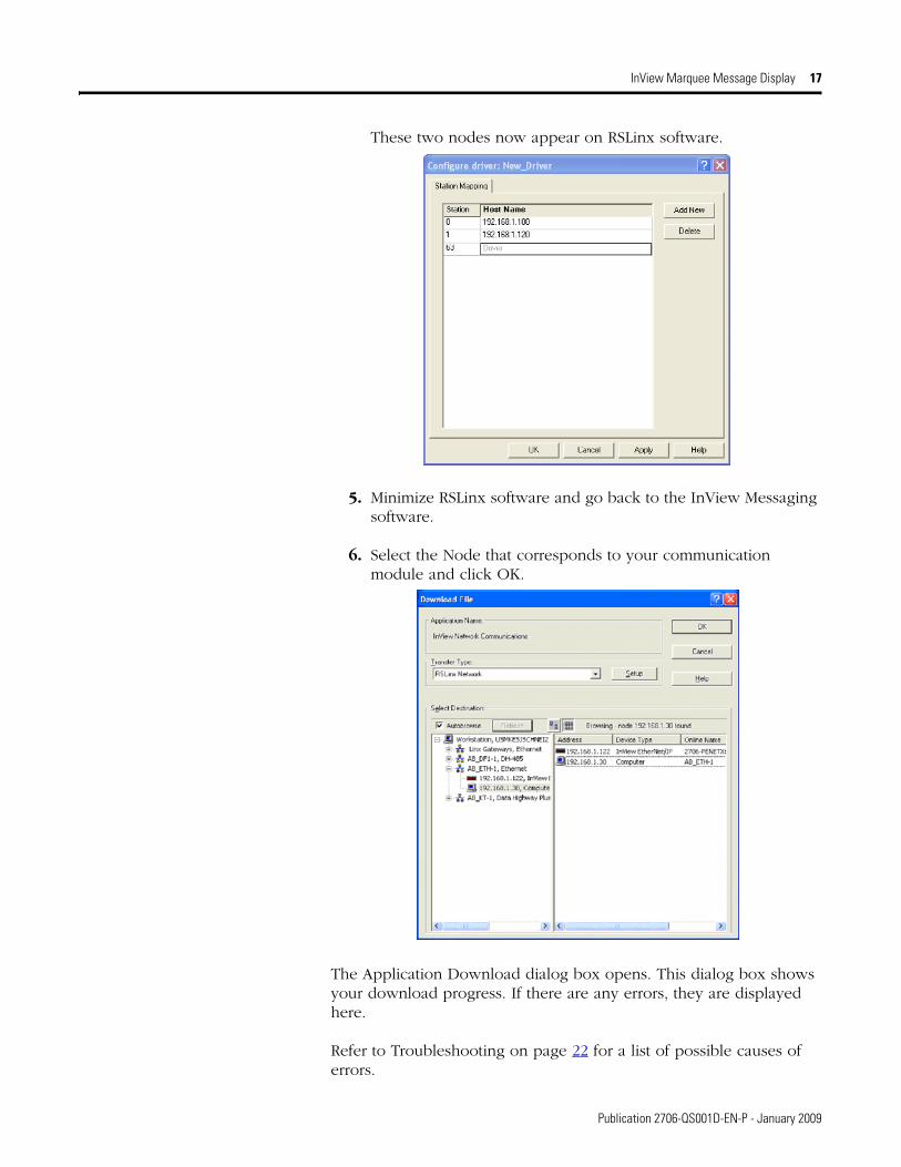
These two nodes now appear on RSLinx software.
5. Minimize RSLinx software and go back to the InView Messaging software.
6. Select the Node that corresponds to your communication module and click OK.
The Application Download dialog box opens. This dialog box shows your download progress. If there are any errors, they are displayed here.
Refer to Troubleshooting on page 22 for a list of possible causes of errors.
Publication 2706-QS001D-EN-P - January 2009

18 InView Marquee Message Display
Once the download is complete, the module restarts. The EtherNet Communication module can now be connected to the message display and is ready to communicate with the message display and the controller.
Configure a TCP/IP Communication Module
Follow these steps to configure a TCP/IP communication module.
What You Need
This list indicates what you need to complete this task:
• Catalog number 2706-P4x, 2706-P7x, 2706-P9x
• Ethernet cable (user supplied)
• Catalog number 2706-PENET1
• RS-232 serial cable (supplied with Ethernet module)
• InView User Manual, publication 2706-UM016
• InView Installation Instructions, publication 2706-IN006
• Communication Module Installation Instructions, publication 2706-IN015
• Communication Module User Manual, publication 2706-UM017
TIP The module may take up to 30 seconds to fully reboot.
Publication 2706-QS001D-EN-P - January 2009

InView Marquee Message Display 19
Equipment Setup
Follow these instructions to connect the 2706-PENET1 communication module for downloading.
• Connect the power to the unit and RS-232 cable as shown.
• Connect the Ethernet cable to the communication module.
TIP TCP/IP is not available for catalog number 2706-P22R. An external 2706-PENET1 module is not required for catalog number 2706-P9x.
Record the MAC address in catalog number 2706-PENET1 before installing a display or communication module. The MAC address can be found on the label near the 2706-PENET1 module.
TIP Verify RSLinx software is not using the serial port.
Publication 2706-QS001D-EN-P - January 2009

20 InView Marquee Message Display
Configure Communication
Follow these steps to configure communication.
From an existing project, start at the main page of the InView Messaging software.
1. Right-click the display you wish to modify and choose Edit Display.
2. In the Edit Display dialog box, click the Communication tab and choose Ethernet TCP/IP as your Download Protocol.
3. In the TCP/IP settings, click Configure Communications.
Publication 2706-QS001D-EN-P - January 2009

InView Marquee Message Display 21
4. In the Ethernet TCP/IP Communications dialog box, type the IP Address of the 2706-PENET1 module, the MAC Address of the communication module, and the Subnet Mask.
5. Click Setup to make the changes in the communication module and click OK to finish.
IMPORTANT There are two Setup buttons. You need to set the IP and MAC as stated in step 4. Click the first Setup button and then restart the 2706-PENET1 module. After it cycles power, click the next Setup button.
TIP Leave the Gateway Address blank unless required for your application.
TIP Your computer needs to be on the same subnet as the communication module to set the communication.
Publication 2706-QS001D-EN-P - January 2009

22 InView Marquee Message Display
Troubleshooting This table shows possible errors and the suggested solutions.
Additional Resources These documents contain additional information concerning related Rockwell Automation products.
You can view or download publications at http://literature.rockwellautomation.com. To order paper copies of technical documentation, contact your local Rockwell Automation distributor or sales representative.
Error Solution
COM1 unresponsive Make sure that RSLinx software is not active on COM1.
The Download File dialog box opens Check to see if the communication module has power.
Make sure that you are using the correct COM port.
TIP For more troubleshooting information, refer to InView Communication Module User Manual, publication 2706-UM017.
Resource Description
InView Marquee Message Display User Manual, publication 2706-UM016
Provides a more detailed description of how to use your InView display.
InView Installation Instructions, publication 2706-IN006
Provides details on installing and wiring InView displays.
Communication Module Installation Instructions, publication 2706-IN015
Provides details on installing and wiring the InView communication module.
InView Communication Module User Manual, publication 2706-UM017
Provides information about using the InView communication module.
Publication 2706-QS001D-EN-P - January 2009

InView Marquee Message Display 23
Notes:
Publication 2706-QS001D-EN-P - January 2009

Publication 2706-QS001D-EN-P - January 2009 24 PN 38176
Rockwell Automation Support
Rockwell Automation provides technical information on the Web to assist you in using its products. At http://support.rockwellautomation.com, you can find technical manuals, a knowledge base of FAQs, technical and application notes, sample code and links to software service packs, and a MySupport feature that you can customize to make the best use of these tools.
For an additional level of technical phone support for installation, configuration, and troubleshooting, we offer TechConnect support programs. For more information, contact your local distributor or Rockwell Automation representative, or visit http://support.rockwellautomation.com.
Installation Assistance
If you experience a problem within the first 24 hours of installation, please review the information that's contained in this manual. You can also contact a special Customer Support number for initial help in getting your product up and running.
New Product Satisfaction Return
Rockwell Automation tests all of its products to ensure that they are fully operational when shipped from the manufacturing facility. However, if your product is not functioning and needs to be returned, follow these procedures.
Allen-Bradley, Rockwell Automation, InView, RSLinx, and TechConnect are trademarks of Rockwell Automation, Inc.
Trademarks not belonging to Rockwell Automation are property of their respective companies.
United States 1.440.646.3434Monday – Friday, 8 a.m. – 5 p.m. EST
Outside United States Please contact your local Rockwell Automation representative for any technical support issues.
United States Contact your distributor. You must provide a Customer Support case number (see phone number above to obtain one) to your distributor in order to complete the return process.
Outside United States Please contact your local Rockwell Automation representative for the return procedure.
Supersedes Publication 2706-QS001C-EN-P - August 2003 Copyright © 2009 Rockwell Automation, Inc. All rights reserved. Printed in the U.S.A.