Embed Size (px)
Citation preview

�Stafsjö Valves AB. SE-618 95 Stavsjö, Sweden. Tel: +46 (0)11-39 31 00. Fax: +46 (0)11-39 30 67. [email protected] www.stafsjo.com
A Bröer Group company
Document: Data sheetProduct: MVSize: DN 50 - DN �200 Issue: �2 Issue date: 2009-09-��
MVEN 1092 PN 10 • EN 1092 PN 16 • ANSI B16.5 Class 150 • ANSI B16.47 Class 150 • JIS B 2238 10K
Stafsjö’s knife gate valve MV is designed for a wide range of applications. Principally, it’s made to handle fluids and suspen-sions up to 5%. Common media are pulp, recycled pulp and waste water, but it’s also used in different applications with sludge, powder, pellets and other solid materials.
The MV-valve is designed of one piece or a two piece valve body in stainless steel, nodular iron or carbon steel. It’s equippedwith a gate in stainless steel and a removable retainer ring, whichsimplifies changing of the seat. Stafsjö’s unique box packing, TwinPack™, gives a tight sealing and assures high operation reliability.
The valve is modular designed and it can easily be providedwith different actuators and accessories. MV can also be up-graded to a control valve.
Stafsjö’s knife gate valve MV is designed, manufactured, inspected and tested according to the European Pressure Equipment Directive (PED 97/23/EC) category II module A1. The valve is therefore CE marked.
The MV-valve is also available in ATEX-design (ATEX 94/9/EC II cat 3 G/D for zone 2 and 22). Please contact Stafsjö or your local representative for advice and information.
Information is only for informational purpose. All specifications are subject to change without notice.

2
Document: Data sheetProduct: MVSize: DN 50 - DN �200 Issue: �2 Issue date: 2009-09-��
Design dataSizes Flange drilling Face-to-face dimension Leakage rate
DN 50 - DN �000 EN �092 PN �0EN �092 PN �6JIS B 2238 �0KANSI B�6.5 Class �50ANSI B�6.47 Class �50BS �0 Table D*
Stafsjö manufactoring standardMSS SP-8�TAPPI TIS 405-8
EN �2266-�:2003 Rate A: no visually detectable leakage is allowed for duration of the test MSS SP-8�
Other sizes on request * Not described in this data sheet Rate A is not applicable for valves equipped with metal seat
Pressure tests
Pressure tests are performed with water at 20º C according to EN 12266-1:2003.Pressure for shell test: 1,5 times maximum allowable working pressure for open valve.Pressure for seat tightness test: 1,1 times maximum allowable differential pressure for closed valve.
Maximum working pressure body at 20°C
Maximum differential pressure in preferred direction at 20°C
Maximum differential pressure inreversed direction at 20°C
DN bar DN bar DN bar (E-body) bar (L-body)
50 - �25 �6 50 - �25 �6 50 - 200 3,5 3,5
�50 - 300 �0 �50 - 300 �0 250 3,0 3,0
350 - 600 6 350 - 600 6 300 - 450 - 3,0
700 - �000 4 700 - �000 4 500 - �000 - -
�200 4 �200 2 or 4 �200 - -
The MV knife gate valves with seat in E/N/V, also manages a certain differential pressure in the reversed direction.
Basic equipmentA. Valve Body
Material Type Maximum temperature °C
Stainless steel (E) �.4408 300
Nodular iron (L) GGG50 200
Carbon steel (C)DN 900 & DN �000
WCC/ASTM A2�6 425
Standard colour valve body L and C: epoxy colour, thickness 140-200µm, RAL 5015.
B. Gate
Material Type Body combination
Stainless steel 3�6/�.440� E/L/C
Stainless steel 304/�.430� L (DN 50 - DN 500)
C. Retainer ring
Material Type Body combination Seat combination
Stainless steel SS 2343 E E/N/V/P/PV/M
Cast iron GG20 L/C E/N/V/P/PV/M
Zinced carbon steel E/L/A U
Standard colour for retainer ring in cast iron: epoxy colour, thickness 140-200µm, RAL 5015.

3
Document: Data sheetProduct: MVSize: DN 50 - DN �200 Issue: �2 Issue date: 2009-09-��
D. Seat
Material Maximum temperature °C
EPDM (E) �20
Nitril (N) �00
Viton (V) �80
PTFE with o-ring nitril (P) �00
PTFE with o-ring viton (PV) �80
Polyurethane (U) 90
Metal with Graf oil (MHT) 300 (E)/200 (L)/425 (C)
Metal with o-ring nitrile/viton (M)
�00/�80
E. Box Packing
Material pH Maximum temperature °C
TwinPackTM (TY) 2-�3 260
PTFE (TF) 0-�4 280
Garlock �27 (TG) �-�2 650
ActuatorsManual Automatic
Hand wheel�) (HW) Pneumatic cylinder (AC)
Chain wheel2) (CW) Electrical motor (EM)
Hand lever2)3) (HL) Hydraulic cylinder2) (MH)
Ratchet wrench2) (RW)
Bevel gear2) (BG)1) For recommended size, see page 5 column E2) For recommended size, see separate data sheet3) Differential pressures in preferred or reversed direction according to design data are not valid for hand lever (HL). Maximum differential pressure in preferred direction at 20°C for DN 50 - DN 200: 4 bar.
Pneumatic cylinder Electric motor – AUMA multi-turn
DN valve Size AC Maximum Force (kN) DN valve AUMA Attachment
50 - �50 �00 3,5 50 - �50 SA 07.� F�0/A
200 - 300 �60 9.0 200 - 250 SA 07.5 F�0/A
350 - 500 200 �4.� 300 - 600 SA �0.� F�0/A
600 - 700 250 22.� 700 - 800 SA �4.� F�4/A
750 - �000 320 36,2 900 - �000 SA �4.5 F�4/A
�200 - - �200 SA �6.� F�6/A
The table above gives recommended cylinder sizes at normal operation with 5 bar air pressure. For other operating conditions, please contact Stafsjö or your local representa-tive for advice.
Electric motors are mounted according to standard ISO 5210. The table above gives recommended motor sizes at normal operation. For other operating conditions, please contact Stafsjö or your local representative for advice.
The actuators are described in detail in separate data sheets. For actuators classified according to ATEX, please contact Stafsjö or your local representative.

4
Document: Data sheetProduct: MVSize: DN 50 - DN �200 Issue: �2 Issue date: 2009-09-��
AccessoriesKnife gate valve
Accessories Model Design
Mechanical limit switch Ersce E�00-00-�� AC�5 6A/230 V
Inductive limit switch ifm electronic IG-2008-ABOA/IG0006 2-wire, 20-250 V AC/DC
ifm electronic IG-3008-BPKG/IG540� 3-wire, �0-36 V DC PNP
Stem extension Short Pipe Length < �.5 m
Long Pipe Length > �.5 m
Water flush gland For MV DN 80 - DN 300
Deflection cone For MV DN 50 - DN 600
V-port For MV DN 50 - DN 600
Positioner for V-port PMV Palmstierna/Metso/ABB
Purge ports MV DN 50 - DN 450 on order
MV DN 500 - DN �200 is equipped with purge ports Pipe thread G�/2” acc. to ISO 228/�
Pneumatic cylinder
Accessories Model Design
Solenoid valve Metal Work mono stable 5/2, series 70 �/4”
Metal Work mono stable 5/2, series 70 �/2”
Magnetic limit switch Elobau �02247 & �0224709 2-wire, �0-250 V AC/DC
Elobau �02290PE & �02290PE09 3-wire, �0-30 V DC
The accessories are described in detail in separate data sheets. For accessories classified according to ATEX, please contact Stafsjö or your local representative.

5
12
8
S TA FS JÖ
13
10
9
5
6
7
17
15
2b
1
16
3
4c
18
5a
5b
2c
2b
4
4b
2a
2
8a
8b
8c
28
20
25
9a
12a
21
10b
4a
10a 11
14
4
4c
4d
4b
Document: Data sheetProduct: MVSize: DN 50 - DN �200 Issue: �2 Issue date: 2009-09-��
Part ListPos. Part Material (Name) Pos. Part Material (Name)
� Hand wheel Epoxy coatedØ 200 - Ø 315 Cast iron GG25> Ø 400 Cast iron (GG20)
7 Beam Aluminium (EN AW-6063-T6)
8 Gland (E-body)Gland (L-body)
Stainless steel (1.4408)Nodular iron (GGG50), epoxy coated
2 Yoke Stainless steel (SS2333-02/304)DN 900 - DN 1200:Cast iron (GG20), Epoxy coated
8a Stud bolt Stainless steel (A2), zinc coated
8b Washer Stainless steel (A2)
8c Nut Stainless steel (A2), zinc coated
2a Bearing Brass (SS5170-00) 9 Box packing* See equipment E
2b Slide washer POM 9a Box bottom support DN 500 - DN 800 HD-polyethylene
2c Bearing Brass (SS5170-00) �0/a/b Valve body See equipment A
3 Stem DN 50 - DN250:Stainless steel (SS2320-02)> DN 300:Stainless steel (SS2383-02)
�� Body gasket PTFE
�2 Retainer ring See equipment C
�2a Locking screw Stainless steel (A2)
�3 Seat* See equipment D
4 Stem nut Brass (CW603N)> DN 800: Brass (SS5453)
�4 Guide strip HD-polyethylenepolyethylene
�5 Bushing Oil-bronze
4a Stem nut holder Stainless steel (SS2333-02) �6 Gate guard, not for HW
Stainless steel (SS2333-02)
4b Screw Stainless steel (A2)
4c Washer Stainless steel (A2) �7 Gate clevis Stainless steel (SS2346-02)
4d Nut Stainless steel (A2) �8 Cylinder See data sheet
5 Tie rod Stainless steel (SS2333-02) 20 Clevis pin Stainless steel (SS2346-02)
5a Washer Stainless steel (A2) 2� Split pin Stainless steel (SS2343-02)
5b Nut Stainless steel (A2) 25 Piston rod Stainless steel (SS2383-02)
6 Gate See equipment B 28 Locking nut Stainless steel (SS2346-02)* Recommended spare parts
One piece body: DN 50 - DN 800 Two piece body: DN 900 - DN �200
6
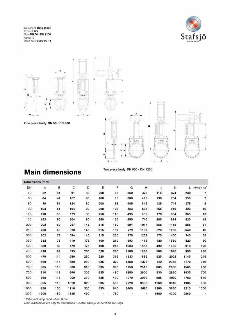
DN A B C D E F G H J K L
50 52 4� 9� 80 200 56 360 475 ��6 674 230 7
65 64 4� �07 80 200 65 380 495 �30 704 250 7
80 79 5� �24 80 200 88 405 545 �35 744 275 8
100 �03 5� �54 80 200 �02 453 593 �55 8�9 323 �0
125 �28 56 �79 80 250 ��6 495 685 �78 884 365 �3
150 �53 60 204 80 250 �30 550 740 205 964 420 �5
200 202 60 267 �45 3�5 �60 694 �0�7 268 ���5 555 3�
250 250 69 320 �45 3�5 �92 779 ��02 320 �250 640 40
300 302 78 374 �45 3�5 230 879 �252 375 �400 740 55
350 332 78 4�9 �75 400 2�0 993 �4�5 420 �550 820 90
400 380 89 479 �75 400 245 �083 �555 490 �690 9�0 �20
450 428 89 535 200 520 280 ��80 �680 560 �820 990 �80
500 470 ��4 580 250 520 3�5 �333 �892 625 2028 ��45 245
600 560 ��4 680 260 635 370 �558 2373 740 2358 �370 340
700 665 ��8 800 3�0 635 390 �750 25�3 865 2650 �565 460
750 7�0 ��8 860 305 635 490 �880 2900 930 2830 �635 700
800 760 ��8 900 3�0 635 490 �970 3030 985 2970 �780 540
900 855 ��8 �0�0 320 635 580 2220 3380 ��60 3340 �985 900
1000 950 �50 ���0 320 635 640 2400 3670 �280 3630 22�5 �500
1200 �200 �50 �335 490 - 750 - - �500 4300 2860 -
E
K
H
C A
B
FG
D
J
S ta fs jö S ta fs jö S ta fs jö
O
STAFSJÖ STAFSJÖ STAFSJÖ
GF
E
AC
H
D
B J
L
K
STAFSJÖ STAFSJÖ STAFSJÖ
GF
E
AC
H
D
B J
L
K
Document: Data sheetProduct: MVSize: DN 50 - DN �200 Issue: �2 Issue date: 2009-09-��
Main dimensionsDimensions (mm)
Wheight kg*
One piece body: DN 50 - DN 800
Two piece body: DN 900 - DN �200
* Valve including hand wheel (HW) Main dimensions are only for information. Contact Stafsjö for certified drawings.
7
DN 50 - DN 65DN 80 - DN 200
DN 250 - DN 300 DN 350 - DN 400DN 450 - DN 600
DN 700 - DN 800
DN 900 - DN 1000
DN 1200
Document: Data sheetProduct: MVSize: DN 50 - DN �200 Issue: �2 Issue date: 2009-09-��
Main dimensionsDimensions (mm)
Wheight kg*
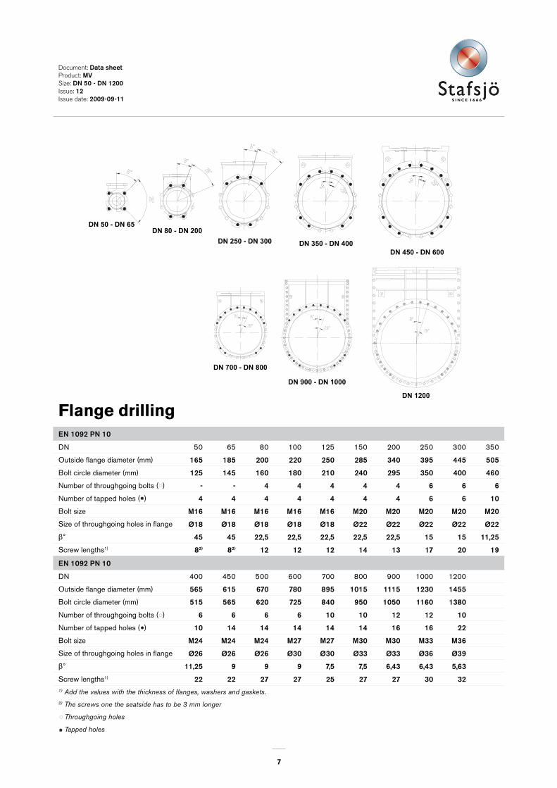
Flange drillingEN �092 PN �0
DN 50 65 80 100 125 150 200 250 300 350
Outside flange diameter (mm) �65 �85 200 220 250 285 340 395 445 505
Bolt circle diameter (mm) �25 �45 �60 �80 2�0 240 295 350 400 460
Number of throughgoing bolts ( ) - - 4 4 4 4 4 6 6 6
Number of tapped holes ( ) 4 4 4 4 4 4 4 6 6 �0
Bolt size M�6 M�6 M�6 M�6 M�6 M20 M20 M20 M20 M20
Size of throughgoing holes in flange Ø�8 Ø�8 Ø�8 Ø�8 Ø�8 Ø22 Ø22 Ø22 Ø22 Ø22
Ⱐ45 45 22,5 22,5 22,5 22,5 22,5 �5 �5 ��,25
Screw lengths1) 82) 82) �2 �2 �2 �4 �3 �7 20 �9
EN �092 PN �0
DN 400 450 500 600 700 800 900 1000 1200
Outside flange diameter (mm) 565 6�5 670 780 895 �0�5 ���5 �230 �455
Bolt circle diameter (mm) 5�5 565 620 725 840 950 �050 ��60 �380
Number of throughgoing bolts ( ) 6 6 6 6 �0 �0 �2 �2 �0
Number of tapped holes ( ) �0 �4 �4 �4 �4 �4 �6 �6 22
Bolt size M24 M24 M24 M27 M27 M30 M30 M33 M36
Size of throughgoing holes in flange Ø26 Ø26 Ø26 Ø30 Ø30 Ø33 Ø33 Ø36 Ø39
Ⱐ��,25 9 9 9 7,5 7,5 6,43 6,43 5,63
Screw lengths1) 22 22 27 27 25 27 27 30 321) Add the values with the thickness of flanges, washers and gaskets.2) The screws one the seatside has to be 3 mm longer
Throughgoing holes
Tapped holes
12121010
Ø30Ø26Ø26Ø22Size of throughgoing holes in flangeB
2ß°
ß°
2ß°
ß°
Bolt size
Screw length
ß°
2ß°2ß°
ß°
15412710278
and the estimated thickness of the gasket.
1) Add the values in the table with the thickness of the pipe flanges, the washers
1) 2217Screw lengths 3025911,2511,25 9ß°
=Throughgoing holes=Tapped holes
Outside flange diam (mm) 780565505 670
600400350 500Size (DN)
B
725620
8M27
8M24
515460
6M24
6M20Bolt size
No. of tapped hole/side. ( )No. of throughgoing bolts ( )Bolt circle diameter (mm)

8
Ду 50 - Ду 65Ду 80 - Ду 150
Ду 200 - Ду 300 Ду 350 - Ду 400Ду 450 - Ду 600
Ду 700 - Ду 800
Ду 900 - Ду 1000
Ду 1200
DN 50 - DN 65DN 80 - DN 150
DN 200 - DN 300 DN 350 - DN 400DN 450 - DN 600
DN 700 - DN 800
DN 900 - DN 1000
DN 1200
Document: Data sheetProduct: MVSize: DN 50 - DN �200 Issue: �2 Issue date: 2009-09-��
EN �092 PN �6
DN 400 450 500 600 700 800 900 1000 1200
Outside flange diameter (mm) 580 640 7�5 840 9�0 �025 ��25 �255 �485
Bolt circle diameter (mm) 525 585 650 770 840 950 �050 ��70 �390
Number of throughgoing bolts ( ) 6 6 6 6 �0 �0 �2 �2 �0
Number of tapped holes ( ) �0 �4 �4 �4 �4 �4 �6 �6 22
Bolt size M27 M27 M30 M33 M33 M36 M36 M39 M45
Size of throughgoing holes in flange Ø30 Ø30 Ø33 Ø36 Ø36 Ø39 Ø39 Ø42 Ø48
Ⱐ��,25 9 9 9 7,5 7,5 6,43 6,43 5,63
Screw lengths1) 22 22 27 27 25 27 27 30 321) Add the values with the thickness of flanges, washers and gaskets.2) The screws one the seatside has to be 3 mm longer
Throughgoing holes
Tapped holes
Flange drillingEN �092 PN �6
DN 50 65 80 100 125 150 200 250 300 350
Outside flange diameter (mm) �65 �85 200 220 250 285 340 405 460 520
Bolt circle diameter (mm) �25 �45 �60 �80 2�0 240 295 355 4�0 470
Number of throughgoing bolts ( ) - - 4 4 4 4 6 6 6 6
Number of tapped holes ( ) 4 4 4 4 4 4 6 6 6 �0
Bolt size M�6 M�6 M�6 M�6 M�6 M20 M20 M24 M24 M24
Size of throughgoing holes in flange Ø�8 Ø�8 Ø�8 Ø�8 Ø�8 Ø22 Ø22 Ø26 Ø26 Ø26
Ⱐ45 45 22,5 22,5 22,5 22,5 �5 �5 �5 ��,25
Screw lengths1) 82) 82) �2 �2 �2 �4 �3 �7 20 �912121010
Ø30Ø26Ø26Ø22Size of throughgoing holes in flangeB
2ß°
ß°
2ß°
ß°
Bolt size
Screw length
ß°
2ß°2ß°
ß°
15412710278
and the estimated thickness of the gasket.
1) Add the values in the table with the thickness of the pipe flanges, the washers
1) 2217Screw lengths 3025911,2511,25 9ß°
=Throughgoing holes=Tapped holes
Outside flange diam (mm) 780565505 670
600400350 500Size (DN)
B
725620
8M27
8M24
515460
6M24
6M20Bolt size
No. of tapped hole/side. ( )No. of throughgoing bolts ( )Bolt circle diameter (mm)
12121010
Ø30Ø26Ø26Ø22Size of throughgoing holes in flangeB
2ß°
ß°
2ß°
ß°
Bolt size
Screw length
ß°
2ß°2ß°
ß°
15412710278
and the estimated thickness of the gasket.
1) Add the values in the table with the thickness of the pipe flanges, the washers
1) 2217Screw lengths 3025911,2511,25 9ß°
=Throughgoing holes=Tapped holes
Outside flange diam (mm) 780565505 670
600400350 500Size (DN)
B
725620
8M27
8M24
515460
6M24
6M20Bolt size
No. of tapped hole/side. ( )No. of throughgoing bolts ( )Bolt circle diameter (mm)

9
DN 80DN 50 - DN 65 DN �00 - DN 200DN 250 - DN 350 DN 400 - DN 450
DN 500 - DN 600
DN 700 - DN 800DN 900
DN �000DN �200
Document: Data sheetProduct: MVSize: DN 50 - DN �200 Issue: �2 Issue date: 2009-09-��
DN 50 - DN 600: ANSI B�6.5 Class �50. > DN 700: ANSI B�6.47 Class �50.
DN 400 450 500 600 700 750 800 900 1000 1200
Outside flange diameter (mm) 597 635 699 8�3 927,� 984,3 �060 ��68,4 �289,� �5��
Bolt circle diameter (mm) 539,8 577,9 635 749,3 863,6 9�4,4 977,9 �085,9 �200,� �422,4
Number of throughgoing bolts ( ) 6 6 6 6 �0 �0 �0 �2 �8 28
Number of tapped holes ( ) �0 �0 �4 �4 �8 �8 �8 20 �8 �6
Bolt size (UNC) �-8 � �/8-7 � �/8-7 � �/4-7 � �/4-7 � �/4-7 � �/2-6 � �/2-6 � �/2-6 � �/2-6
Size of throughgoing holes in flange Ø30 Ø33 Ø33 Ø36 Ø36 Ø36 Ø42 Ø42 Ø42 Ø42
Ⱐ��,25 ��,25 9 9 6,43 6,43 6,43 5,63 5 4,0�
Screw lengths1) 22 22 27 27 25 25 27 27 33 321) Add the values with the thickness of flanges, washers and gaskets.2) The screws one the seatside has to be 3 mm longer3) The screws on the seatside has to be 10 mm longer for face-to-face TAPPI
Throughgoing holes
Tapped holes
Flange drillingDN 50 - DN 600: ANSI B�6.5 Class �50. > DN 700: ANSI B�6.47 Class �50.
DN 50 65 80 100 125 150 200 250 300 350
Outside flange diameter (mm) �52,4 �77,8 �90,5 228,6 254 297,4 342,9 406,4 482,6 533
Bolt circle diameter (mm) �20,7 �39,7 �52,4 �90,5 2�5,9 24�,3 298,5 362 43�,8 476,3
Number of throughgoing bolts ( ) - - 2 4 4 4 4 6 6 6
Number of tapped holes ( ) 4 4 2 4 4 4 4 6 6 6
Bolt size (UNC) 5/8-�� 5/8-�� 5/8-�� 5/8-�� 3/4-�0 3/4-�0 3/4-�0 7/8-9 7/8-9 �-8
Size of throughgoing holes in flange Ø�8 Ø�8 Ø�8 Ø�8 Ø22 Ø22 Ø22 Ø26 Ø26 Ø30
β° 45 45 22,5 22,5 22,5 22,5 22,5 �5 �5 �5
Screw lengths1) 82) 82) �2 �2 �2 �4 �33) �7 20 �912121010
Ø30Ø26Ø26Ø22Size of throughgoing holes in flangeB
2ß°
ß°
2ß°
ß°
Bolt size
Screw length
ß°
2ß°2ß°
ß°
15412710278
and the estimated thickness of the gasket.
1) Add the values in the table with the thickness of the pipe flanges, the washers
1) 2217Screw lengths 3025911,2511,25 9ß°
=Throughgoing holes=Tapped holes
Outside flange diam (mm) 780565505 670
600400350 500Size (DN)
B
725620
8M27
8M24
515460
6M24
6M20Bolt size
No. of tapped hole/side. ( )No. of throughgoing bolts ( )Bolt circle diameter (mm)
12121010
Ø30Ø26Ø26Ø22Size of throughgoing holes in flangeB
2ß°
ß°
2ß°
ß°
Bolt size
Screw length
ß°
2ß°2ß°
ß°
15412710278
and the estimated thickness of the gasket.
1) Add the values in the table with the thickness of the pipe flanges, the washers
1) 2217Screw lengths 3025911,2511,25 9ß°
=Throughgoing holes=Tapped holes
Outside flange diam (mm) 780565505 670
600400350 500Size (DN)
B
725620
8M27
8M24
515460
6M24
6M20Bolt size
No. of tapped hole/side. ( )No. of throughgoing bolts ( )Bolt circle diameter (mm)
�0
DN 700 - DN 750 DN 800
DN 900 - DN �000
DN 80 - DN �50DN 50 - DN 65DN 200 - DN 250 DN 300 DN 350 - DN 400 DN 450 - DN 500 DN 600
Document: Data sheetProduct: MVSize: DN 50 - DN �200 Issue: �2 Issue date: 2009-09-��
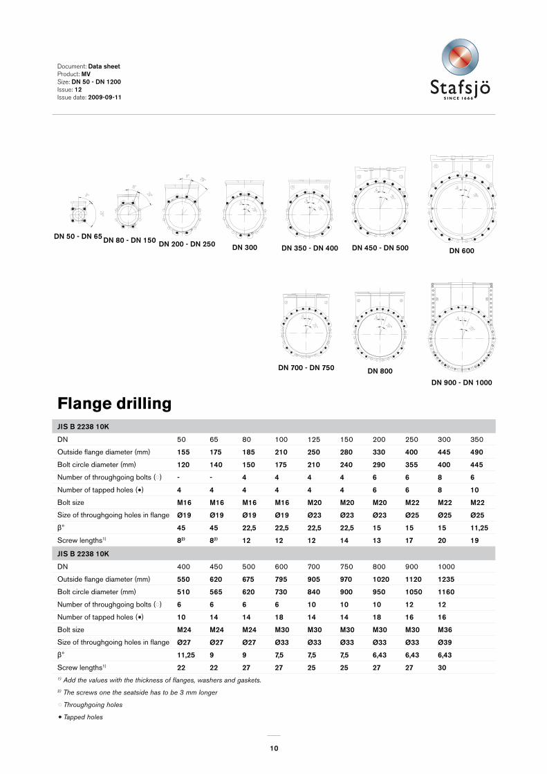
Flange drillingJIS B 2238 �0K
DN 50 65 80 100 125 150 200 250 300 350
Outside flange diameter (mm) �55 �75 �85 2�0 250 280 330 400 445 490
Bolt circle diameter (mm) �20 �40 �50 �75 2�0 240 290 355 400 445
Number of throughgoing bolts ( ) - - 4 4 4 4 6 6 8 6
Number of tapped holes ( ) 4 4 4 4 4 4 6 6 8 �0
Bolt size M�6 M�6 M�6 M�6 M20 M20 M20 M22 M22 M22
Size of throughgoing holes in flange Ø�9 Ø�9 Ø�9 Ø�9 Ø23 Ø23 Ø23 Ø25 Ø25 Ø25
Ⱐ45 45 22,5 22,5 22,5 22,5 �5 �5 �5 ��,25
Screw lengths1) 82) 82) �2 �2 �2 �4 �3 �7 20 �9
JIS B 2238 �0K
DN 400 450 500 600 700 750 800 900 1000
Outside flange diameter (mm) 550 620 675 795 905 970 �020 ��20 �235
Bolt circle diameter (mm) 5�0 565 620 730 840 900 950 �050 ��60
Number of throughgoing bolts ( ) 6 6 6 6 �0 �0 �0 �2 �2
Number of tapped holes ( ) �0 �4 �4 �8 �4 �4 �8 �6 �6
Bolt size M24 M24 M24 M30 M30 M30 M30 M30 M36
Size of throughgoing holes in flange Ø27 Ø27 Ø27 Ø33 Ø33 Ø33 Ø33 Ø33 Ø39
Ⱐ��,25 9 9 7,5 7,5 7,5 6,43 6,43 6,43
Screw lengths1) 22 22 27 27 25 25 27 27 301) Add the values with the thickness of flanges, washers and gaskets.2) The screws one the seatside has to be 3 mm longer
Throughgoing holes
Tapped holes
12121010
Ø30Ø26Ø26Ø22Size of throughgoing holes in flangeB
2ß°
ß°
2ß°
ß°
Bolt size
Screw length
ß°
2ß°2ß°
ß°
15412710278
and the estimated thickness of the gasket.
1) Add the values in the table with the thickness of the pipe flanges, the washers
1) 2217Screw lengths 3025911,2511,25 9ß°
=Throughgoing holes=Tapped holes
Outside flange diam (mm) 780565505 670
600400350 500Size (DN)
B
725620
8M27
8M24
515460
6M24
6M20Bolt size
No. of tapped hole/side. ( )No. of throughgoing bolts ( )Bolt circle diameter (mm)