Embed Size (px)
Citation preview
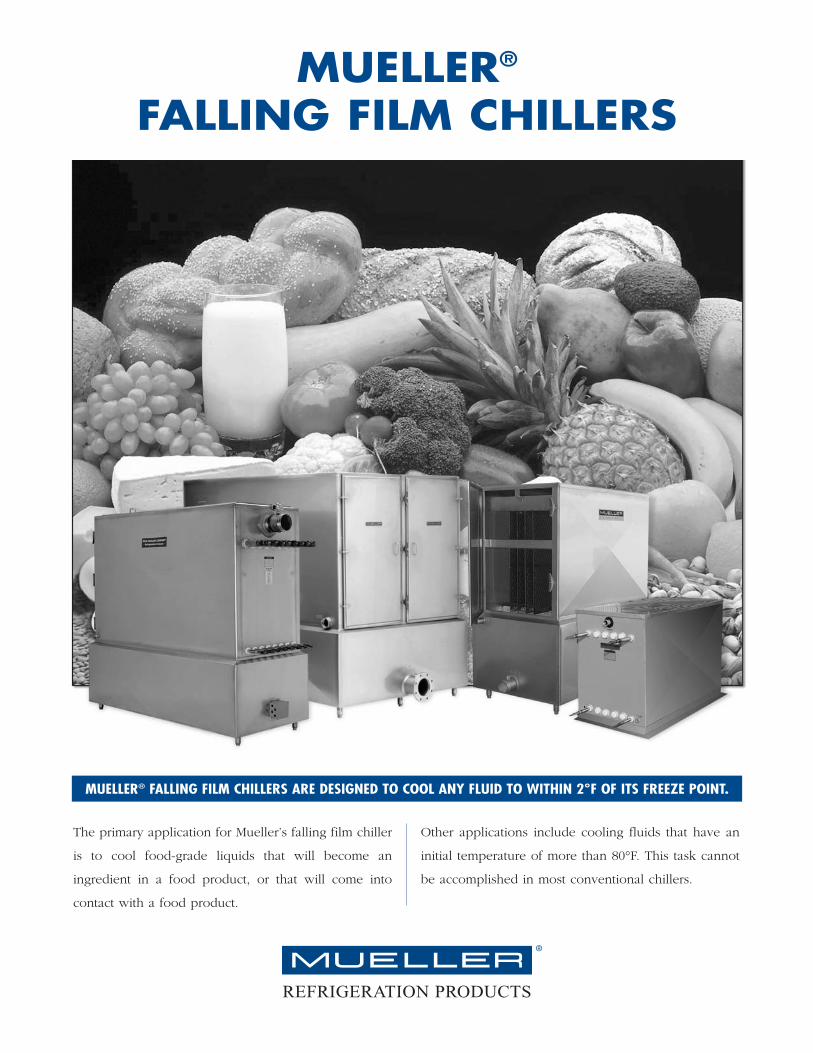
The primary application for Mueller’s falling film chiller
is to cool food-grade liquids that will become an
ingredient in a food product, or that will come into
contact with a food product.
Other applications include cooling fluids that have an
initial temperature of more than 80°F. This task cannot
be accomplished in most conventional chillers.
MUELLER® FALLING FILM CHILLERS ARE DESIGNED TO COOL ANY FLUID TO WITHIN 2°F OF ITS FREEZE POINT.
®
MUELLER®
FALLING FILM CHILLERS
REFRIGERATION PRODUCTS
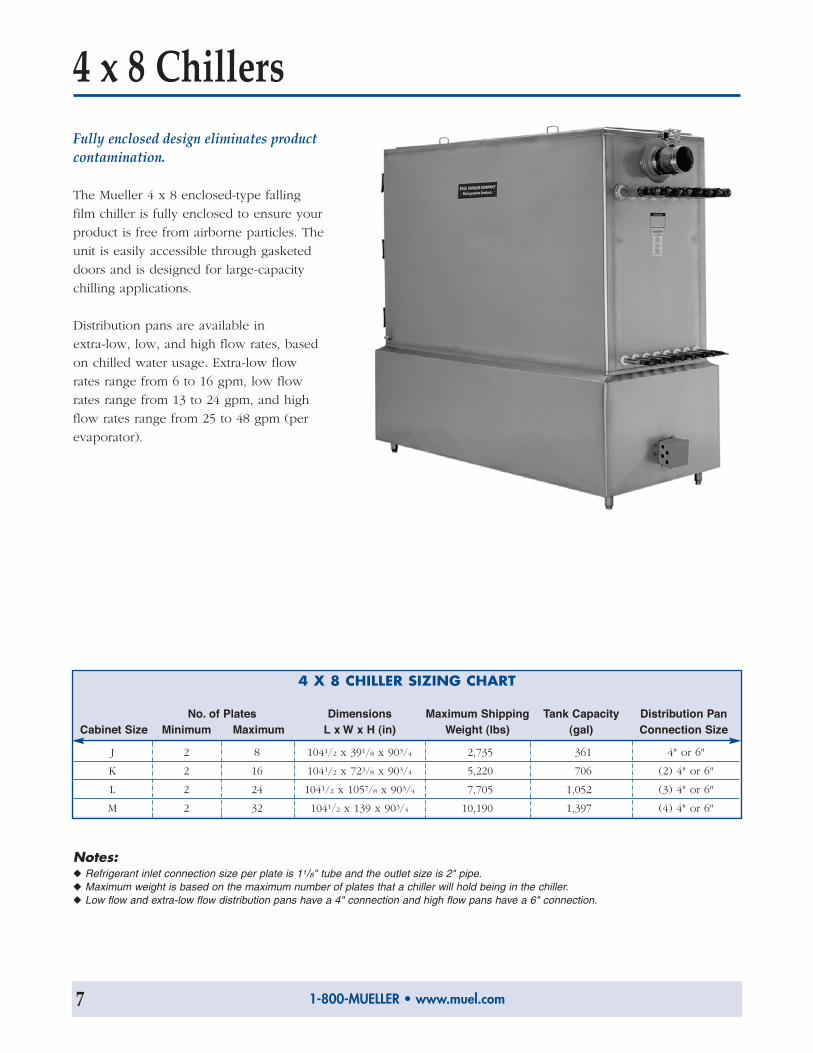
4 x 8 ChillersFully enclosed design eliminates productcontamination.
The Mueller 4 x 8 enclosed-type falling
film chiller is fully enclosed to ensure your
product is free from airborne particles. The
unit is easily accessible through gasketed
doors and is designed for large-capacity
chilling applications.
Distribution pans are available in
extra-low, low, and high flow rates, based
on chilled water usage. Extra-low flow
rates range from 6 to 16 gpm, low flow
rates range from 13 to 24 gpm, and high
flow rates range from 25 to 48 gpm (per
evaporator).
4 X 8 CHILLER SIZING CHART
No. of Plates Dimensions Maximum Shipping Tank Capacity Distribution PanCabinet Size Minimum Maximum L x W x H (in) Weight (lbs) (gal) Connection Size
J 2 8 1041/2 x 391/8 x 903/4 2,735 361 4" or 6"
K 2 16 1041/2 x 723/8 x 903/4 5,220 706 (2) 4" or 6"
L 2 24 1041/2 x 1057/8 x 903/4 7,705 1,052 (3) 4" or 6"
M 2 32 1041/2 x 139 x 903/4 10,190 1,397 (4) 4" or 6"
Notes:◆ Refrigerant inlet connection size per plate is 11/8" tube and the outlet size is 2" pipe.◆ Maximum weight is based on the maximum number of plates that a chiller will hold being in the chiller.◆ Low flow and extra-low flow distribution pans have a 4" connection and high flow pans have a 6" connection.
1-800-MUELLER • www.muel.com7
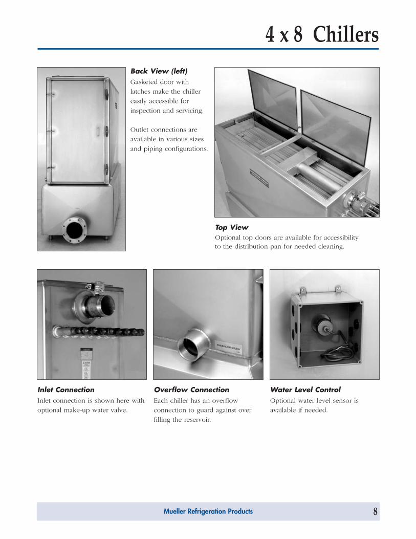
4 x 8 ChillersBack View (left)Gasketed door with
latches make the chiller
easily accessible for
inspection and servicing.
Outlet connections are
available in various sizes
and piping configurations.
Inlet ConnectionInlet connection is shown here with
optional make-up water valve.
Overflow ConnectionEach chiller has an overflow
connection to guard against over
filling the reservoir.
Water Level ControlOptional water level sensor is
available if needed.
Top ViewOptional top doors are available for accessibilityto the distribution pan for needed cleaning.
Mueller Refrigeration Products 8
Process Automation Worldwide Brands: LFETM • PartlowTM • PMATM • RustrakTM • West TM
Customer Service +1 800.390.6405Technical Support +1 800.866.6659
www.partlow.com • www.danaherindustrialcontrols.com
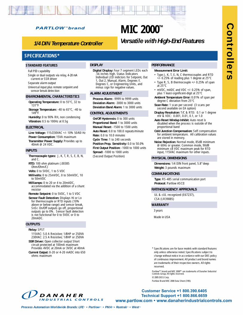
MIC 2000™
Versatile with High-End Features1/4 DIN Temperature Controller
SPECIFICATIONS*
DISPLAYDigital Display: Four 7 segment LEDs each
.56 inches high. Status IndicatorsIndividual LED indictors for Setpoint, Out1, Out 2, Manual, Alarm, Degrees F,Degrees C, or Engineering Units, andminus sign for negative values.
ALARM ADJUSTMENTProcess Alarm: -9999 to 9999 units Deviation Alarm: -3000 to 3000 units Deviation Band Alarm: 1 to 3000 units
CONTROL ADJUSTMENTS On/Off Hysteresis: 0 to 300 units Proportional Band: 1 to 3000 units Manual Reset: -1500 to 1500 unitsAuto Reset: 0.0 to 100.0 repeats/minute Rate: 0.0 to 10.0 minutes Cycle Time: 1 to 240 seconds Position Prop. Sensitivity: 0.0 to 50.0%First Output Position: -1000 to 1000 unitsSpread: -1000 to 1000 units(Second Output Position)
STANDARD FEATURES
Full PID capabilitySingle or dual outputs via relay, 4-20 mA
current or SSR driverSeparate alarm outputUniversal input plus remote setpoint and
sensor break detection
ENVIRONMENTAL CHARACTERISTICSOperating Temperature: 0 to 55° C, 32 to
131° FStorage Temperature: -40 to 65° C, -40 to
149° FHumidity: 0 to 90% RH, non condensingVibration: 0.5 to 100Hz at 0.5g
ELECTRICALLine Voltage: 115/230VAC +/- 10% 50/60 HzPower Consumption: 15VA maximumTransmitter Power Supply: Provides up to
40mA @ 24 VDC.
INPUTSThermocouple types: J, K, T, R, S, E, B, N,
and C.RTD: 100 ohm platinum (.00385
Ohm/Ohm/C)Volts: 0 to 5VDC, 1 to 5 VDCMillivolts: 0 to 25mVDC, 0 to 50mVDC, 10
to 50mVDCMilliamps: 0 to 20 or 4 to 20mADC,
accommodated via the addition of a shuntresistor
Remote Setpoint: 0 to 5VDC, 1 to 5 VDCSensor Fault Detection: Displays Hi or Lo
for thermocouple or RTD inputs (10%above or below range) and sensor break,SnSr. On/Off outputs go off, proportionaloutputs go to 0%. Sensor fault detectionis not functional for 0 to 5VDC or 0 to20mADC.
OUTPUTSRelay: SPST
115VAC: 5.0 A Resistive; 1/8HP or 250VA230VAC: 2.5 A Resistive; 1/8HP or 250VA
SSR Driver: Open collector output Shortcircuit protected at 100mA maximumProvides 4VDC at 20mA or 3VDC at 40mA
Current Output: 0-20 or 4-20 mADC into 650ohms maximum
PERFORMANCEMeasurement Error Limit:• Type J, K, T, E, N, C thermocouples and RTD
+/- 0.25% of reading plus 1 degree at 25° C• Type R, S, B thermocouple +/- 0.25% of span
at 25° C• mVDC, mADC and VDC +/- 0.25% of span,
plus 1 least-significent-digit at 25° CAmbient Temperature Error: 0.01% of span per
degree C deviation from 25° CScan Rate: 1 scan per second (3 scans per
second available on EA option)Display Resolution: T/C & RTD: 0.1 or 1 degree
mV & VDC: 0.001, 0.01, 0.1, or 1.0Auto Reset Windup Inhibit: Auto reset is
disabled when the process is outside of theproportional band
Cold Junction Compensation: Self compensationfor ambient temperature. All calibration valuesare stored in memory.
Noise Rejection: Normal mode, 85dB minimum@ 60Hz or greater. Common mode, 90dBminimum ±8 VDC maximum peak for RTDinput, 115VAC maximum for other inputs.
PHYSICAL DIMENSIONSDimensions: 1/4 DIN front panel, 5.8" deepWeight: 3 pounds maximum
COMMUNICATIONSType: RS-485 serial communication portProtocol: Partlow ASCII
RATINGS/AGENCY APPROVALS UL & cUL recognized (E67237), CSA (LR39885)
WARRANTY
3 years
Made in USA
* Specifications are for base models with standard featuresonly unless otherwise noted. Specifications subject tochange without notice in accordance with our DBS policyof continuous improvement. All product and brand namesare trademarks of their respective owners. All rightsreserved.
Partlow™ brand and MIC 2000™ are trademarks of Danaher IndustrialControls Group. All rights reserved. © 2005 DICG Corp.Partlow Brand MIC 2000 Data Sheet (7/05)
Co
ntro
llers
for Industrial/CommercialEvaporator Defrosting
Specifications, Applications,Service Instructions & Parts
HANSEN TECHNOLOGIESCORPORATION
Bulletin F100bAugust, 1994
FROST MASTER® &FROST MASTER® PLUS
DEFROST CONTROLLERS
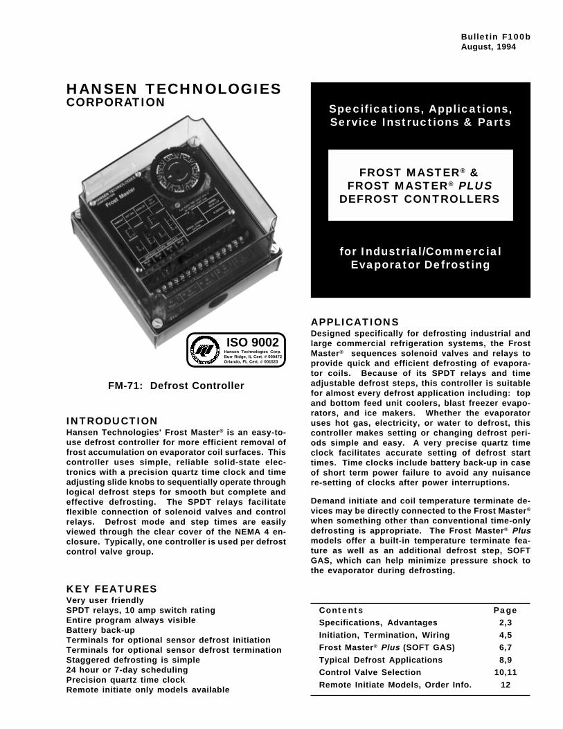
INTRODUCTIONHansen Technologies' Frost Master® is an easy-to-use defrost controller for more efficient removal offrost accumulation on evaporator coil surfaces. Thiscontroller uses simple, reliable solid-state elec-tronics with a precision quartz time clock and timeadjusting slide knobs to sequentially operate throughlogical defrost steps for smooth but complete andeffective defrosting. The SPDT relays facilitateflexible connection of solenoid valves and controlrelays. Defrost mode and step times are easilyviewed through the clear cover of the NEMA 4 en-closure. Typically, one controller is used per defrostcontrol valve group.
KEY FEATURESVery user friendlySPDT relays, 10 amp switch ratingEntire program always visibleBattery back-upTerminals for optional sensor defrost initiationTerminals for optional sensor defrost terminationStaggered defrosting is simple24 hour or 7-day schedulingPrecision quartz time clockRemote initiate only models available
FM-71: Defrost Controller
APPLICATIONSDesigned specifically for defrosting industrial andlarge commercial refrigeration systems, the FrostMaster® sequences solenoid valves and relays toprovide quick and efficient defrosting of evapora-tor coils. Because of its SPDT relays and timeadjustable defrost steps, this controller is suitablefor almost every defrost application including: topand bottom feed unit coolers, blast freezer evapo-rators, and ice makers. Whether the evaporatoruses hot gas, electricity, or water to defrost, thiscontroller makes setting or changing defrost peri-ods simple and easy. A very precise quartz timeclock facilitates accurate setting of defrost starttimes. Time clocks include battery back-up in caseof short term power failure to avoid any nuisancere-setting of clocks after power interruptions.
Demand initiate and coil temperature terminate de-vices may be directly connected to the Frost Master®
when something other than conventional time-onlydefrosting is appropriate. The Frost Master® Plusmodels offer a built-in temperature terminate fea-ture as well as an additional defrost step, SOFTGAS, which can help minimize pressure shock tothe evaporator during defrosting.
Contents PageSpecifications, Advantages 2,3
Initiation, Termination, Wiring 4,5
Frost Master® Plus (SOFT GAS) 6,7
Typical Defrost Applications 8,9
Control Valve Selection 10,11
Remote Initiate Models, Order Info. 12
Hansen Technologies Corp.Burr Ridge, IL Cert. # 000472Orlando, FL Cert. # 001523
ISO 9002
2
MATERIAL SPECIFICATIONSDefrost Steps:
PUMPOUT 0 to 15 minutesHOT GAS 0 to 45 minutesEQUALIZE 0 to 5 minutesFAN DELAY 0 to 5 minutes(For Plus models, see page 6.)
Relays: SPDT, 10 amp rating eachDefrost Interval:
24 hour clock, 96 settings (15 min. increments)7-day clock, 84 settings (2 hour increments)Remote initiate models, user selectable
Battery Back-Up: 90 hours for quartz time clockPower: 115V 50/60Hz; 230V 50/60HzTerminal Strip: Accepts 14-22 AWG wire sizesController Temperature Range: 32 to 120F (0°C to
50°C) ambientEnclosure: NEMA 4, high impact polycarbonate
clear cover, gasketedAuxiliary ¼" spade terminals for optional defrost
initiate or temperature terminate
ADVANTAGESThe control settings are in refrigeration terms, "de-frost steps", which make setting and adjusting theFrost Master® controller simple and easy to under-stand. The defrost starts with the removal of liquidrefrigerant from the evaporator before starting thefrost melt period. PUMPOUT (step 1) reduces theload caused by the cold residual liquid refrigerantand exposes more internal surface area to the hotgas. HOT GAS (step 2) introduces the hot gas (orother frost melting medium) to the evaporator for aset period of time or can be temperature terminat-ed. EQUALIZE (step 3) reduces the relatively highpressure inside the newly defrosted evaporator,thus eliminating the sudden, sometimes radical surgein suction pressure when the suction solenoid valveis reopened. FAN DELAY (step 4) freezes the waterdroplets from the melted frost to the evaporatorsurface instead of permitting them to blow into therefrigerated space. NORMAL refrigeration resumesby starting the fan motor. Usage of all steps is atthe designer's option and any step may be skippedby setting the defrost step time adjustment to zero.
When used in conjunction with a Demand InitiateDefrost device, this controller can limit the numberof defrosts per day or week by not defrosting unlessnecessary; the time clock can be used to preventdefrost from happening when it would not beadvantageous. Temperature terminate contacts areprovided to optionally connect a thermostat or otherdevice for minimized defrost time.
The Remote Initiate models (clockless) require onlyan external, momentary dry contact closure of theinitiate terminals from a computer, PLC, push but-ton, etc. to start a defrost cycle. This facilitatesgreat flexibility in various and unusual applica-tions. Frost Master® Plus models are availablehaving an additional defrost step, SOFT GAS, tominimize pressure shock when hot gas is intro-duced to evaporator. Also, these models have abuilt-in temperature terminate feature; see page 6.
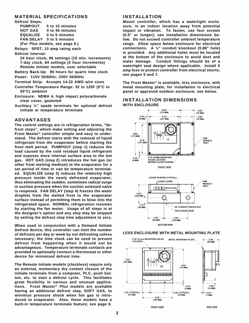
INSTALLATIONMount controller, which has a watertight enclo-sure, in an indoor location away from potentialimpact or vibration. To fasten, use four screws(0.5" or longer); see installation dimensions be-low. Do not exceed controller ambient temperaturerange. Allow space below enclosure for electricalconnections. A ½" conduit knockout (0.88" hole)is provided. Any additional holes must be locatedat the bottom of the enclosure to avoid dust andwater damage. Conduit fittings should be of awatertight seal design where applicable. Install 5amp fuse to protect controller from electrical shorts;see pages 5 and 7.
The Frost Master® is available, less enclosure, withmetal mounting plate, for installation in electricalpanel or approved outdoor enclosure; see below.
INSTALLATION DIMENSIONSWITH ENCLOSURE
LESS ENCLOSURE WITH METAL MOUNTING PLATE
6.89(175 MM)
�
6.18(157 MM)
�
2.95(75 MM)
�
2.95(75 MM)
�
FMPMODELSONLY
FRONT VIEW
0.19 (5 MM) MOUNTINGHOLES LOCATEDBEHIND COVER SCREWS
�0.34(9 MM)
�
6.18(157 MM)
�
6.89(175 MM)
�
0.34(9 MM)
�
FMPMODELSONLY
.05 CONDUIT KNOCK-OUT�
ENCLOSURE BASE
5.05(128 MM)
�
BOTTOM VIEW
3.45(88 MM)
�
1.13(29 MM)
�
3.94(100 MM)
�
COVER SCREWS (TYPICAL)
CLEAR COVER
0.19 (5 mm) MOUNTING HOLES4 PLACES
� METAL MOUNTING PLATE 3.38(86 MM)
�
6.88(175 MM)
�
0.56(14 MM)
�
0.03(1 MM)
�
SIDE VIEWFRONT VIEW
3.00 (TYPICAL)(76 MM)�
0.19(5 MM)
�
6.25(159 MM)
�
1.63 (TYPICAL)(41 MM)�
7.25(184 MM)
�
3
FROST MASTER® DEFROST CONTROLLER
PUMPOUT: 0 to 15 minutes. The PUMPOUTstep helps in the removal of liquid refrigerant fromthe evaporator before defrosting begins. Less liq-uid means more internal evaporator surface isexposed to entering hot gas. It also reduces theamount of liquid accommodated by the system duringdefrost.
HOT GAS: 0 to 45 minutes. The HOT GAS stepbegins the actual melting of the frost accumula-tion. The amount of time required to remove thefrost is dependent on many factors including thefollowing: design of evaporator, quantity of frostaccumulation, quality and quantity of hot gas sup-ply, size of valves, etc. A fairly accurate way ofsetting this time is by observing several defrostsof the evaporator to estimate the amount of timerequired, possibly by using the Manual Steppingfeature of the Frost Master®. Be sure that the HOTGAS step is long enough to entirely remove everyportion of the frost. Partial removal of frost is notacceptable because it will tend to increase in massafter each defrost, eventually causing a large frost/ice problem. To help assure complete defrostingwhere the HOT GAS step duration is desired to bekept to a minimum, a coil clean temperature termi-nate device is an option. (See TERMINATE, page 4and 6).
EQUALIZE: 0 to 5 minutes. The EQUALIZEstep permits gradual reduction of the pressure in-side the evaporator after defrosting to near suctionpressure. This is accomplished by either a bleed-down solenoid valve by-passing the suction shut-offvalve or by merely allowing the surrounding ambi-ent temperature to cool the evaporator. This steplowers the internal pressure and the likelihood ofevaporator, piping and component shock when thesuction stop valve is opened. Equalization alsoreduces the impact of pressure changes upon thesuction accumulator. Radical pressure changescause unnecessary loading and unloading of com-pressors and also encourage pumps to cavitate.Observing the evaporator pressure gauge duringthis step may help determine the most appropriatetime setting.
FAN DELAY: 0 to 5 minutes. This step re-sumes normal refrigeration but delays the evaporatorfan operation for the set time. This delay enablesthe remaining water droplets from the melted frostto freeze to the surface of the evaporator, thuspreventing them from blowing into the refrigeratedspace when air flow resumes.
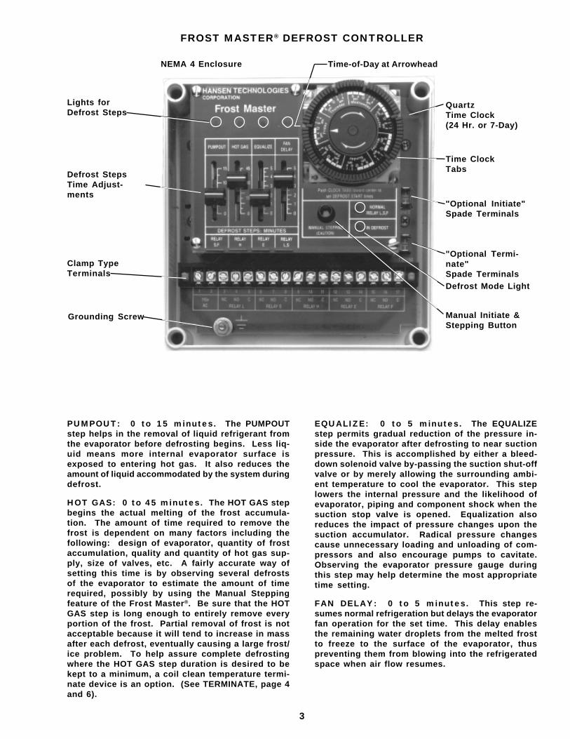
Lights forDefrost Steps
Time-of-Day at ArrowheadNEMA 4 Enclosure
Clamp TypeTerminals
Grounding Screw
Defrost StepsTime Adjust-ments
"Optional Initiate"Spade Terminals
QuartzTime Clock(24 Hr. or 7-Day)
Time ClockTabs
Manual Initiate &Stepping Button
Defrost Mode Light
"Optional Termi-nate"Spade Terminals
4
SETTING DEFROST START TIMESTo set the time-of-day or day-of-the-week (7-dayclock) rotate the time clock clockwise until theexact time matches up with the triangle shapedtime marker located on the inner dial. To set de-frost start times, push the time clock tabs next tothe desired times towards the center. Defrosts willbegin at each of these times, provided the initiateterminals are closed (for time-only defrost, a facto-ry installed, removable jumper closes theseterminals; see DEMAND INITIATE).
Typically, no more than a 1/3 of a plant's evapora-tors should be in defrost at one time because anadequate supply of hot gas is required. About 100psig minimum of hot gas pressure should be avail-able for ammonia or a pressure equivalent to 40F(4°C) saturation pressure plus about 30 psi linepressure drop for other refrigerants.
For multiple evaporators with individual defrostcontrollers, if necessary the defrost start time set-tings can be staggered by 15 minutes (or multiplesthereof) and the 24 hour quartz time clock willmaintain this interval accurately. (The 7-day timeclock can stagger start times by 2 hours or mul-tiples.) At least one tab must be set away from thecenter of the time clock between defrosts. There-fore, a ½ hour minimum between defrosts for 24hour time clocks and a 4 hour minimum for 7-dayclocks is required.
SETTING DEFROST STEPSEach defrost step has its own slide knob time ad-justment. After determining the proper setting,move each slide knob to a position correspondingto an appropriate amount of time (minutes). De-frost step lights will illuminate during each respectivestep to inform operator of defrost status. Afterobserving several defrosts, the setting may be easilyre-adjusted to more closely match the actual con-ditions of the application.
DEFROST STEP AND MODE LIGHTSThese lights inform the operator of defrost control-ler status. A green L.E.D. light indicates normalrefrigeration. A combination of two red L.E.D. lightsindicates the defrost mode and its particular step.If no lights are on, check power to controller.
MANUAL STEPPINGA manual stepping button is provided for initiatingand optionally advancing through the defrost steps.This will be helpful when testing electrical opera-tion and connections, as well as manually initiatinga defrost during a period of unusual frost accumu-lation. IMPORTANT: Control devices (solenoidvalves, control relays, etc.) can operate while us-ing the manual stepping button. Care should betaken not to advance the defrost steps so rapidlythat the evaporator, piping, and other refrigerantcomponents experience sudden or unfavorable con-ditions.
DEMAND INITIATEThe defrost initiate feature is a normally open (N.O.)pair of ¼" spade terminals (INIT). They must beclosed and a time clock tab must trip before a de-frost will begin. In other words, initiate for a clockequipped defrost controller will only occur if calledfor by an initiation device during a clock scheduleddefrost period. On the other hand, a "clockless"Remote Initiate Model (FM-01, FM-02, FMP-01) couldinitiate defrost any time the initiate device closedthe terminals. The Frost Master® is supplied with afactory installed jumper wire which closes the ini-tiate terminals. If a remote demand initiate defrostdevice is to be used for a clock model, simply cutand remove this small, horizontal jumper wire whichis soldered between the base of the initiate termi-nals. Then connect the normally open leads fromthe initiate device to the initiate spade terminals.
The demand defrost cycle will occur only when thetime clock tabs are pushed in and when the initiatedevice calls for defrost. This prevents defrostsfrom occurring at inappropriate times. At least onetime clock tab must be set away from the center ofthe time clock between defrost initiate times to "RE-ARM" controller. If there are periods when a demanddefrost would not be advantageous (i.e. when load-ing a room or at the beginning of a work shift), pullthe time clock tabs which correspond to these timesaway from the center of the time clock. A defrostwill not be able to start during these times. Shoulda defrost be requested by the initiate device duringthis restricted time period, it will not start until thenext following pushed-in time clock tab time isreached. This is also ideal in preventing too manyor several evaporators in the same room from goinginto defrost at once. It is feasible to use a computeror similar device in lieu of a frost sensor for de-mand initiate.
Frost Master® Remote Initiate Models (less any timeclock) offer many features suitable for computerinitiate, manual push button, and demand defrostdevices only; see page 12.
TERMINATEThe defrost terminate feature is a normally open(N.O.) pair of ¼" spade terminals. When there is aclosure of these terminals during the HOT GAS steponly, the Frost Master® ceases hot gas defrost sup-ply, advances to EQUALIZE and proceeds at the settime intervals through to the other steps. The coilclean terminate device is usually a customer sup-plied thermostat (temperature switch) set at about40F (4°C) whose sensing bulb is located at the lastplace on the evaporator coil where frost or ice re-mains during a defrost. By ending the HOT GASstep as soon as the coil is clean, a quick and effi-cient defrost occurs. When using a terminate devicebe sure that the HOT GAS step duration setting islong enough to always permit a complete defrost. Ifnot sure, set to maximum. If the terminate device orthermostat is not actuated, the hot gas supply orother frost melting medium will be terminated bythis step time setting. For defrost controller withbuilt-in Temperature Terminate feature and sensor,see Frost Master® Plus models on page 6.
5
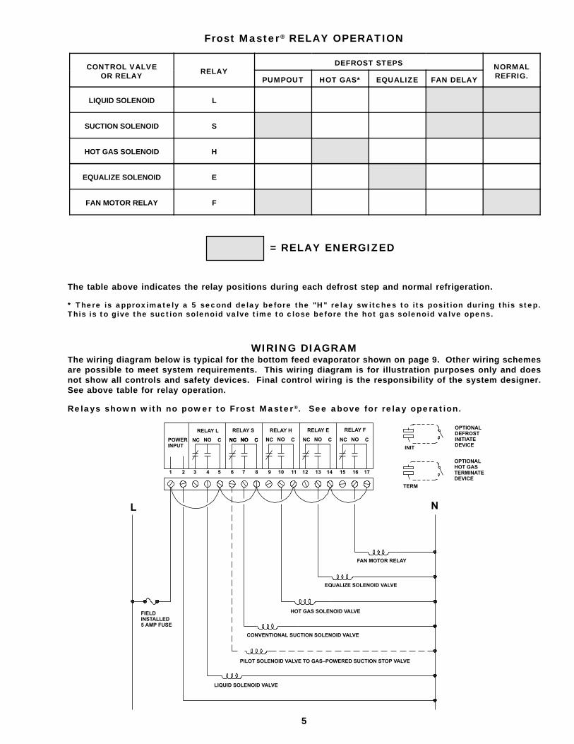
CONTROL VALVEOR RELAY RELAY
DEFROST STEPS NORMALREFRIG.PUMPOUT HOT GAS* EQUALIZE FAN DELAY
LIQUID SOLENOID L
SUCTION SOLENOID S
HOT GAS SOLENOID H
EQUALIZE SOLENOID E
FAN MOTOR RELAY F
The table above indicates the relay positions during each defrost step and normal refrigeration.
* There is approximately a 5 second delay before the "H" relay switches to its position during this step.This is to give the suction solenoid valve time to close before the hot gas solenoid valve opens.
= RELAY ENERGIZED
Frost Master® RELAY OPERATION
WIRING DIAGRAMThe wiring diagram below is typical for the bottom feed evaporator shown on page 9. Other wiring schemesare possible to meet system requirements. This wiring diagram is for illustration purposes only and doesnot show all controls and safety devices. Final control wiring is the responsibility of the system designer.See above table for relay operation.
Relays shown with no power to Frost Master®. See above for relay operation.
POWERINPUT
RELAY L
NC NO C NC NO C
RELAY S RELAY H RELAY E RELAY F
NC NO CNC NO C NC NO C NC NO C
1 2 3 4 5 6 7 8 9 10 11 12 13 14 15 16 17
OPTIONALDEFROSTINITIATEDEVICE
OPTIONALHOT GASTERMINATEDEVICE
INIT
TERM
N
FAN MOTOR RELAY
EQUALIZE SOLENOID VALVE
HOT GAS SOLENOID VALVE
CONVENTIONAL SUCTION SOLENOID VALVE
PILOT SOLENOID VALVE TO GAS–POWERED SUCTION STOP VALVE
LIQUID SOLENOID VALVE
FIELDINSTALLED5 AMP FUSE
L
6
HANSEN TECNOLOGIESCORPORATION
Frost Master Plus
PUMPOUT SOFT GAS HOT GAS EQUALIZE FANDELAY
45
30
15
0
45
30
15
0
5
4
3
2
1
0
5
4
3
2
1
0
5
4
3
2
1
0
5
4
3
2
1
0
5
4
3
2
1
0
5
4
3
2
1
0
5
4
3
2
1
0
5
4
3
2
1
0
10
8
6
4
2
0
DEFROST STEPS: MINUTES
RELAYS F1
RELAYSG
RELAYSG H1
RELAYE
RELAYL, S
INIT
Push CLOCK TABS toward centerto set DEFROST START times
MANUALSTEPPING(CAUTION)
NORMALRELAY L, S, F
IN DEFROST
TERMINATETEMP, °F
TEMP,SENSOR
1 2 3 4 5 6 7 8 9 10 11 12 13 14 15 16 17 18 19 20
NC NO C NC NO C NC NO C NC NO C NC NO C NC NO C
RELAY L RELAY S RELAY SG RELAY H RELAY E RELAY F
115V50/60 HZ
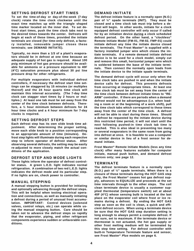
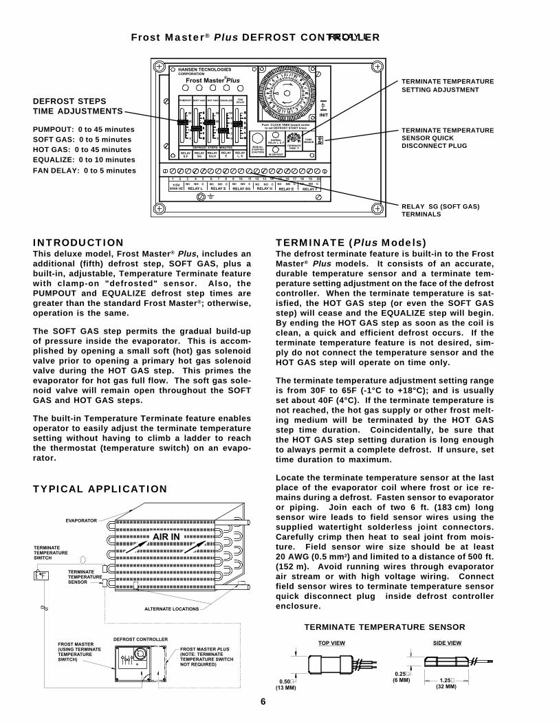
Frost Master® Plus DEFROST CONTROLLER
DEFROST STEPSTIME ADJUSTMENTS
PUMPOUT: 0 to 45 minutesSOFT GAS: 0 to 5 minutesHOT GAS: 0 to 45 minutesEQUALIZE: 0 to 10 minutesFAN DELAY: 0 to 5 minutes
TERMINATE TEMPERATURESENSOR QUICKDISCONNECT PLUG
TERMINATE (Plus Models)The defrost terminate feature is built-in to the FrostMaster® Plus models. It consists of an accurate,durable temperature sensor and a terminate tem-perature setting adjustment on the face of the defrostcontroller. When the terminate temperature is sat-isfied, the HOT GAS step (or even the SOFT GASstep) will cease and the EQUALIZE step will begin.By ending the HOT GAS step as soon as the coil isclean, a quick and efficient defrost occurs. If theterminate temperature feature is not desired, sim-ply do not connect the temperature sensor and theHOT GAS step will operate on time only.
The terminate temperature adjustment setting rangeis from 30F to 65F (-1°C to +18°C); and is usuallyset about 40F (4°C). If the terminate temperature isnot reached, the hot gas supply or other frost melt-ing medium will be terminated by the HOT GASstep time duration. Coincidentally, be sure thatthe HOT GAS step setting duration is long enoughto always permit a complete defrost. If unsure, settime duration to maximum.
Locate the terminate temperature sensor at the lastplace of the evaporator coil where frost or ice re-mains during a defrost. Fasten sensor to evaporatoror piping. Join each of two 6 ft. (183 cm) longsensor wire leads to field sensor wires using thesupplied watertight solderless joint connectors.Carefully crimp then heat to seal joint from mois-ture. Field sensor wire size should be at least20 AWG (0.5 mm2) and limited to a distance of 500 ft.(152 m). Avoid running wires through evaporatorair stream or with high voltage wiring. Connectfield sensor wires to terminate temperature sensorquick disconnect plug inside defrost controllerenclosure.
TERMINATE TEMPERATURESETTING ADJUSTMENT
RELAY SG (SOFT GAS)TERMINALS
®
INTRODUCTIONThis deluxe model, Frost Master® Plus, includes anadditional (fifth) defrost step, SOFT GAS, plus abuilt-in, adjustable, Temperature Terminate featurewith clamp-on "defrosted" sensor. Also, thePUMPOUT and EQUALIZE defrost step times aregreater than the standard Frost Master®; otherwise,operation is the same.
The SOFT GAS step permits the gradual build-upof pressure inside the evaporator. This is accom-plished by opening a small soft (hot) gas solenoidvalve prior to opening a primary hot gas solenoidvalve during the HOT GAS step. This primes theevaporator for hot gas full flow. The soft gas sole-noid valve will remain open throughout the SOFTGAS and HOT GAS steps.
The built-in Temperature Terminate feature enablesoperator to easily adjust the terminate temperaturesetting without having to climb a ladder to reachthe thermostat (temperature switch) on an evapo-rator.
TYPICAL APPLICATION
RELAY L
AIR IN
EVAPORATOR
TERMINATETEMPERATURESWITCH
TERMINATETEMPERATURESENSOR
ALTERNATE LOCATIONS
FROST MASTER(USING TERMINATETEMPERATURESWITCH)
DEFROST CONTROLLER
FROST MASTER(NOTE: TERMINATETEMPERATURE SWITCHNOT REQUIRED)
PLUS
0.50(13 MM)
�
TOP VIEW
0.25(6 MM)
�1.25
(32 MM)�
SIDE VIEW
TERMINATE TEMPERATURE SENSOR
7
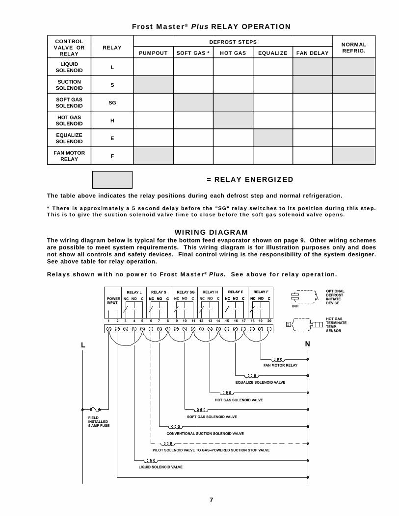
CONTROLVALVE OR
RELAYRELAY
DEFROST STEPS NORMALREFRIG.PUMPOUT SOFT GAS * HOT GAS EQUALIZE FAN DELAY
LIQUIDSOLENOID
L
SUCTIONSOLENOID
S
SOFT GASSOLENOID
SG
HOT GASSOLENOID H
EQUALIZESOLENOID
E
FAN MOTORRELAY
F
Frost Master® Plus RELAY OPERATION
WIRING DIAGRAMThe wiring diagram below is typical for the bottom feed evaporator shown on page 9. Other wiring schemesare possible to meet system requirements. This wiring diagram is for illustration purposes only and doesnot show all controls and safety devices. Final control wiring is the responsibility of the system designer.See above table for relay operation.
Relays shown with no power to Frost Master® Plus. See above for relay operation.
= RELAY ENERGIZED
The table above indicates the relay positions during each defrost step and normal refrigeration.
* There is approximately a 5 second delay before the "SG" relay switches to its position during this step.This is to give the suction solenoid valve time to close before the soft gas solenoid valve opens.
POWERINPUT
RELAY L
NC NO C NC NO C
RELAY S RELAY SG RELAY H RELAY F
NC NO CNC NO C NC NO C NC NO C
1 2 3 4 5 6 7 8 9 10 11 12 13 14 15 16 17 18 19 20
OPTIONALDEFROSTINITIATEDEVICE
HOT GASTERMINATETEMP.SENSOR
INIT
N
FAN MOTOR RELAY
EQUALIZE SOLENOID VALVE
HOT GAS SOLENOID VALVE
SOFT GAS SOLENOID VALVE
PILOT SOLENOID VALVE TO GAS–POWERED SUCTION STOP VALVE
LIQUID SOLENOID VALVE
FIELDINSTALLED5 AMP FUSE
L
RELAY E
NC NO C
RELAY F
NC NO C
RELAY F
NC NO C
CONVENTIONAL SUCTION SOLENOID VALVE
8
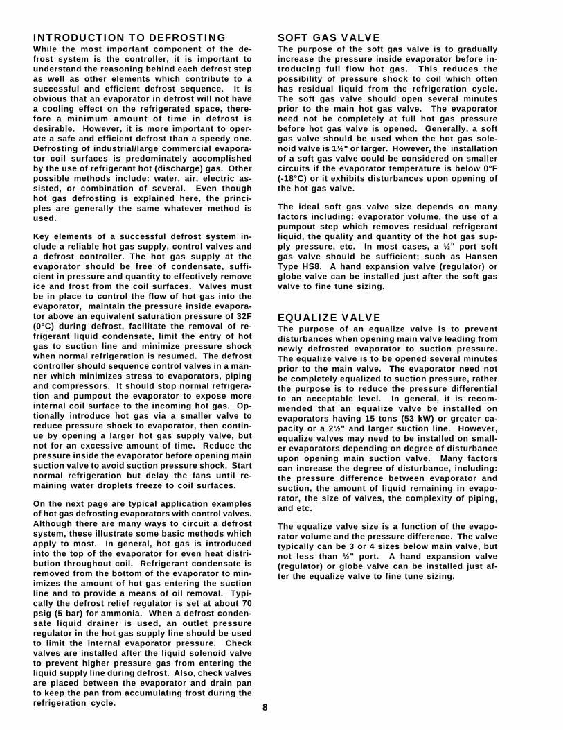
SOFT GAS VALVEThe purpose of the soft gas valve is to graduallyincrease the pressure inside evaporator before in-troducing full flow hot gas. This reduces thepossibility of pressure shock to coil which oftenhas residual liquid from the refrigeration cycle.The soft gas valve should open several minutesprior to the main hot gas valve. The evaporatorneed not be completely at full hot gas pressurebefore hot gas valve is opened. Generally, a softgas valve should be used when the hot gas sole-noid valve is 1½" or larger. However, the installationof a soft gas valve could be considered on smallercircuits if the evaporator temperature is below 0°F(-18°C) or it exhibits disturbances upon opening ofthe hot gas valve.
The ideal soft gas valve size depends on manyfactors including: evaporator volume, the use of apumpout step which removes residual refrigerantliquid, the quality and quantity of the hot gas sup-ply pressure, etc. In most cases, a ½" port softgas valve should be sufficient; such as HansenType HS8. A hand expansion valve (regulator) orglobe valve can be installed just after the soft gasvalve to fine tune sizing.
EQUALIZE VALVEThe purpose of an equalize valve is to preventdisturbances when opening main valve leading fromnewly defrosted evaporator to suction pressure.The equalize valve is to be opened several minutesprior to the main valve. The evaporator need notbe completely equalized to suction pressure, ratherthe purpose is to reduce the pressure differentialto an acceptable level. In general, it is recom-mended that an equalize valve be installed onevaporators having 15 tons (53 kW) or greater ca-pacity or a 2½" and larger suction line. However,equalize valves may need to be installed on small-er evaporators depending on degree of disturbanceupon opening main suction valve. Many factorscan increase the degree of disturbance, including:the pressure difference between evaporator andsuction, the amount of liquid remaining in evapo-rator, the size of valves, the complexity of piping,and etc.
The equalize valve size is a function of the evapo-rator volume and the pressure difference. The valvetypically can be 3 or 4 sizes below main valve, butnot less than ½" port. A hand expansion valve(regulator) or globe valve can be installed just af-ter the equalize valve to fine tune sizing.
INTRODUCTION TO DEFROSTINGWhile the most important component of the de-frost system is the controller, it is important tounderstand the reasoning behind each defrost stepas well as other elements which contribute to asuccessful and efficient defrost sequence. It isobvious that an evaporator in defrost will not havea cooling effect on the refrigerated space, there-fore a minimum amount of time in defrost isdesirable. However, it is more important to oper-ate a safe and efficient defrost than a speedy one.Defrosting of industrial/large commercial evapora-tor coil surfaces is predominately accomplishedby the use of refrigerant hot (discharge) gas. Otherpossible methods include: water, air, electric as-sisted, or combination of several. Even thoughhot gas defrosting is explained here, the princi-ples are generally the same whatever method isused.
Key elements of a successful defrost system in-clude a reliable hot gas supply, control valves anda defrost controller. The hot gas supply at theevaporator should be free of condensate, suffi-cient in pressure and quantity to effectively removeice and frost from the coil surfaces. Valves mustbe in place to control the flow of hot gas into theevaporator, maintain the pressure inside evapora-tor above an equivalent saturation pressure of 32F(0°C) during defrost, facilitate the removal of re-frigerant liquid condensate, limit the entry of hotgas to suction line and minimize pressure shockwhen normal refrigeration is resumed. The defrostcontroller should sequence control valves in a man-ner which minimizes stress to evaporators, pipingand compressors. It should stop normal refrigera-tion and pumpout the evaporator to expose moreinternal coil surface to the incoming hot gas. Op-tionally introduce hot gas via a smaller valve toreduce pressure shock to evaporator, then contin-ue by opening a larger hot gas supply valve, butnot for an excessive amount of time. Reduce thepressure inside the evaporator before opening mainsuction valve to avoid suction pressure shock. Startnormal refrigeration but delay the fans until re-maining water droplets freeze to coil surfaces.
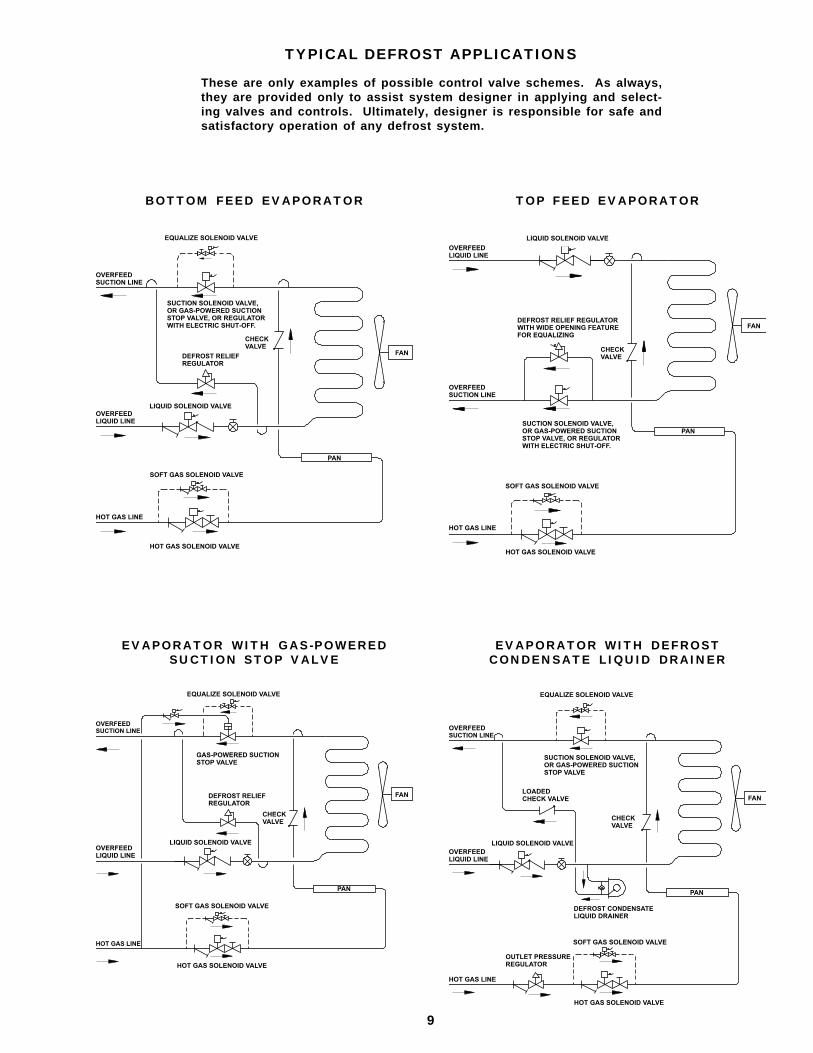
On the next page are typical application examplesof hot gas defrosting evaporators with control valves.Although there are many ways to circuit a defrostsystem, these illustrate some basic methods whichapply to most. In general, hot gas is introducedinto the top of the evaporator for even heat distri-bution throughout coil. Refrigerant condensate isremoved from the bottom of the evaporator to min-imizes the amount of hot gas entering the suctionline and to provide a means of oil removal. Typi-cally the defrost relief regulator is set at about 70psig (5 bar) for ammonia. When a defrost conden-sate liquid drainer is used, an outlet pressureregulator in the hot gas supply line should be usedto limit the internal evaporator pressure. Checkvalves are installed after the liquid solenoid valveto prevent higher pressure gas from entering theliquid supply line during defrost. Also, check valvesare placed between the evaporator and drain panto keep the pan from accumulating frost during therefrigeration cycle.
9
TYPICAL DEFROST APPLICATIONS
These are only examples of possible control valve schemes. As always,they are provided only to assist system designer in applying and select-ing valves and controls. Ultimately, designer is responsible for safe andsatisfactory operation of any defrost system.
BOTTOM FEED EVAPORATOR TOP FEED EVAPORATOR
EVAPORATOR WITH GAS-POWEREDSUCTION STOP VALVE
EVAPORATOR WITH DEFROSTCONDENSATE LIQUID DRAINER
EQUALIZE SOLENOID VALVE
OVERFEEDSUCTION LINE
SUCTION SOLENOID VALVE,OR GAS-POWERED SUCTIONSTOP VALVE, OR REGULATORWITH ELECTRIC SHUT-OFF.
CHECKVALVE
DEFROST RELIEFREGULATOR
FAN
LIQUID SOLENOID VALVEOVERFEEDLIQUID LINE
SOFT GAS SOLENOID VALVE
HOT GAS LINE
HOT GAS SOLENOID VALVE
PAN
OVERFEEDLIQUID LINE
LIQUID SOLENOID VALVE
FANDEFROST RELIEF REGULATORWITH WIDE OPENING FEATUREFOR EQUALIZING
CHECKVALVE
OVERFEEDSUCTION LINE
SUCTION SOLENOID VALVE,OR GAS-POWERED SUCTIONSTOP VALVE, OR REGULATORWITH ELECTRIC SHUT-OFF.
SOFT GAS SOLENOID VALVE
PAN
HOT GAS LINE
HOT GAS SOLENOID VALVE
EQUALIZE SOLENOID VALVE
GAS-POWERED SUCTIONSTOP VALVE
DEFROST RELIEFREGULATOR
CHECKVALVE
OVERFEEDSUCTION LINE
LIQUID SOLENOID VALVE
SOFT GAS SOLENOID VALVE
OVERFEEDLIQUID LINE
HOT GAS LINE
HOT GAS SOLENOID VALVE
PAN
FAN
EQUALIZE SOLENOID VALVE
OVERFEEDSUCTION LINE
SUCTION SOLENOID VALVE,OR GAS-POWERED SUCTIONSTOP VALVE
LOADEDCHECK VALVE
CHECKVALVE
OVERFEEDLIQUID LINE
LIQUID SOLENOID VALVE
DEFROST CONDENSATELIQUID DRAINER
SOFT GAS SOLENOID VALVE
HOT GAS SOLENOID VALVE
HOT GAS LINE
OUTLET PRESSUREREGULATOR
PAN
FAN
10
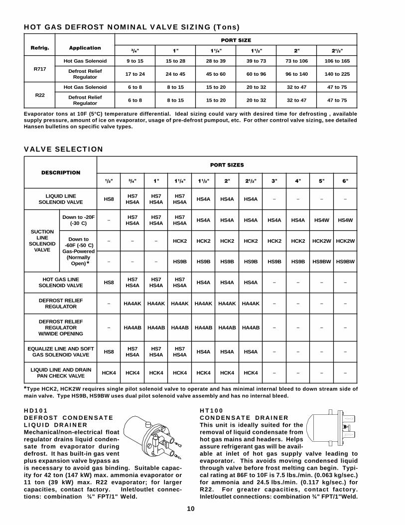
HOT GAS DEFROST NOMINAL VALVE SIZING (Tons)
������� ����� ���
��������
���� �� ����� ����� �� �����
717R
dioneloSsaGtoH 51ot9 82ot51 93ot82 37ot93 601ot37 561ot601
feileRtsorfeDrotalugeR
42ot71 54ot42 06ot54 69ot06 041ot69 522ot041
22R
dioneloSsaGtoH 8ot6 51ot8 02ot51 23ot02 74ot23 57ot74
feileRtsorfeDrotalugeR
8ot6 51ot8 02ot51 23ot02 74ot23 57ot74
Evaporator tons at 10F (5°C) temperature differential. Ideal sizing could vary with desired time for defrosting , availablesupply pressure, amount of ice on evaporator, usage of pre-defrost pumpout, etc. For other control valve sizing, see detailedHansen bulletins on specific valve types.
HD101DEFROST CONDENSATELIQUID DRAINERMechanical/non-electrical floatregulator drains liquid conden-sate from evaporator duringdefrost. It has built-in gas ventplus expansion valve bypass asis necessary to avoid gas binding. Suitable capac-ity for 42 ton (147 kW) max. ammonia evaporator or11 ton (39 kW) max. R22 evaporator; for largercapacities, contact factory. Inlet/outlet connec-tions: combination ¾" FPT/1" Weld.
VALVE SELECTION
���������
��������
� �� � �� �� �� �� �� �� �� �� �� �� �� �� ��
ENILDIUQILEVLAVDIONELOS
8SH7SHA4SH
7SHA4SH
7SHA4SH
A4SH A4SH A4SH − − − −
NOITCUSENIL
DIONELOSEVLAV
F02-otnwoD)C03-( − 7SH
A4SH7SHA4SH
7SHA4SH
A4SH A4SH A4SH A4SH A4SH W4SH W4SH
otnwoD)C05-(F06-derewoP-saG
yllamroN()nepO
− − − 2KCH 2KCH 2KCH 2KCH 2KCH 2KCH W2KCH W2KCH
− − − B9SH B9SH B9SH B9SH B9SH B9SH WB9SH WB9SH
ENILSAGTOHEVLAVDIONELOS
8SH7SHA4SH
7SHA4SH
7SHA4SH
A4SH A4SH A4SH − − − −
FEILERTSORFEDROTALUGER − KA4AH KA4AH KA4AH KA4AH KA4AH KA4AH − − − −
FEILERTSORFEDROTALUGER
GNINEPOEDIW/W− BA4AH BA4AH BA4AH BA4AH BA4AH BA4AH − − − −
TFOSDNAENILEZILAUQEEVLAVDIONELOSSAG
8SH7SHA4SH
7SHA4SH
7SHA4SH
A4SH A4SH A4SH − − − −
NIARDDNAENILDIUQILEVLAVKCEHCNAP
4KCH 4KCH 4KCH 4KCH 4KCH 4KCH 4KCH − − − −
*Type HCK2, HCK2W requires single pilot solenoid valve to operate and has minimal internal bleed to down stream side ofmain valve. Type HS9B, HS9BW uses dual pilot solenoid valve assembly and has no internal bleed.
*
HT100CONDENSATE DRAINERThis unit is ideally suited for theremoval of liquid condensate fromhot gas mains and headers. Helpsassure refrigerant gas will be avail-able at inlet of hot gas supply valve leading toevaporator. This avoids moving condensed liquidthrough valve before frost melting can begin. Typi-cal rating at 86F to 10F is 7.5 lbs./min. (0.063 kg/sec.)for ammonia and 24.5 lbs./min. (0.117 kg/sec.) forR22. For greater capacities, contact factory.Inlet/outlet connections: combination ¾" FPT/1"Weld.
11
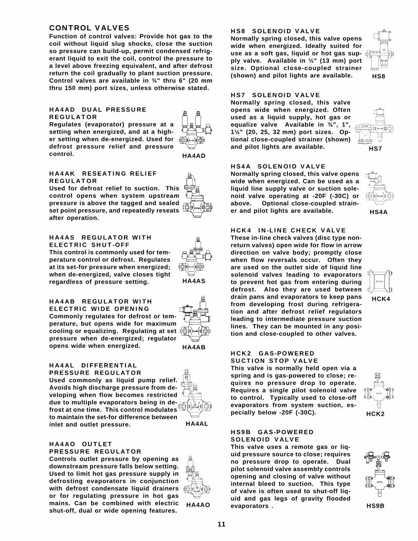
CONTROL VALVESFunction of control valves: Provide hot gas to thecoil without liquid slug shocks, close the suctionso pressure can build-up, permit condensed refrig-erant liquid to exit the coil, control the pressure toa level above freezing equivalent, and after defrostreturn the coil gradually to plant suction pressure.Control valves are available in ¾" thru 6" (20 mmthru 150 mm) port sizes, unless otherwise stated.
HA4AD DUAL PRESSUREREGULATORRegulates (evaporator) pressure at asetting when energized, and at a high-er setting when de-energized. Used fordefrost pressure relief and pressurecontrol.
HA4AK RESEATING RELIEFREGULATORUsed for defrost relief to suction. Thiscontrol opens when system upstreampressure is above the tagged and sealedset point pressure, and repeatedly reseatsafter operation.
HA4AS REGULATOR WITHELECTRIC SHUT-OFFThis control is commonly used for tem-perature control or defrost. Regulatesat its set-for pressure when energized;when de-energized, valve closes tightregardless of pressure setting.
HA4AB REGULATOR WITHELECTRIC WIDE OPENINGCommonly regulates for defrost or tem-perature, but opens wide for maximumcooling or equalizing. Regulating at setpressure when de-energized; regulatoropens wide when energized.
HA4AL DIFFERENTIALPRESSURE REGULATORUsed commonly as liquid pump relief.Avoids high discharge pressure from de-veloping when flow becomes restricteddue to multiple evaporators being in de-frost at one time. This control modulatesto maintain the set-for difference betweeninlet and outlet pressure.
HA4AO OUTLETPRESSURE REGULATORControls outlet pressure by opening asdownstream pressure falls below setting.Used to limit hot gas pressure supply indefrosting evaporators in conjunctionwith defrost condensate liquid drainersor for regulating pressure in hot gasmains. Can be combined with electricshut-off, dual or wide opening features.
HA4AB
HA4AD
HA4AL
HA4AO HS9B
HA4AS
HCK2
HS8 SOLENOID VALVENormally spring closed, this valve openswide when energized. Ideally suited foruse as a soft gas, liquid or hot gas sup-ply valve. Available in ½" (13 mm) portsize. Optional close-coupled strainer(shown) and pilot lights are available.
HS7 SOLENOID VALVENormally spring closed, this valveopens wide when energized. Oftenused as a liquid supply, hot gas orequalize valve Available in ¾", 1",1¼" (20, 25, 32 mm) port sizes. Op-tional close-coupled strainer (shown)and pilot lights are available.
HS4A SOLENOID VALVENormally spring closed, this valve openswide when energized. Can be used as aliquid line supply valve or suction sole-noid valve operating at -20F (-30C) orabove. Optional close-coupled strain-er and pilot lights are available.
HCK4 IN-LINE CHECK VALVEThese in-line check valves (disc type non-return valves) open wide for flow in arrowdirection on valve body; promptly closewhen flow reversals occur. Often theyare used on the outlet side of liquid linesolenoid valves leading to evaporatorsto prevent hot gas from entering duringdefrost. Also they are used betweendrain pans and evaporators to keep pansfrom developing frost during refrigera-tion and after defrost relief regulatorsleading to intermediate pressure suctionlines. They can be mounted in any posi-tion and close-coupled to other valves.
HCK2 GAS-POWEREDSUCTION STOP VALVEThis valve is normally held open via aspring and is gas-powered to close; re-quires no pressure drop to operate.Requires a single pilot solenoid valveto control. Typically used to close-offevaporators from system suction, es-pecially below -20F (-30C).
HS9B GAS-POWEREDSOLENOID VALVEThis valve uses a remote gas or liq-uid pressure source to close; requiresno pressure drop to operate. Dualpilot solenoid valve assembly controlsopening and closing of valve withoutinternal bleed to suction. This typeof valve is often used to shut-off liq-uid and gas legs of gravity floodedevaporators .
HS4A
HS8
HS7
HCK4
12
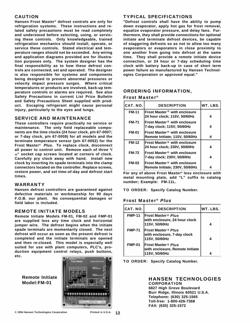
CAUTIONHansen Frost Master® defrost controls are only forrefrigeration systems. These instructions and re-lated safety precautions must be read completelyand understood before selecting, using, or servic-ing these controls. Only knowledgeable, trainedrefrigeration mechanics should install, operate, orservice these controls. Stated electrical and tem-perature ranges should not be exceeded. Any wiringand application diagrams provided are for illustra-tion purposes only. The system designer has thefinal responsibility as to how these defrost con-trols are connected, set and operated. The designeris also responsible for systems and componentsbeing designed to prevent abnormal pressures orvelocity impact pressure surges. Where criticaltemperatures or products are involved, back-up tem-perature controls or alarms are required. See alsoSafety Precautions in current List Price Bulletinand Safety Precautions Sheet supplied with prod-uct. Escaping refrigerant might cause personalinjury, particularly to the eyes and lungs.
SERVICE AND MAINTENANCEThese controllers require practically no service ormaintenance. The only field replaceable compo-nents are the time clocks (24 hour clock, p/n 67-0007;or 7-day clock, p/n 67-0009) for all models and theterminate temperature sensor (p/n 67-0052) for theFrost Master® Plus. To replace clock, disconnectall power to control unit. Remove each of three 5/32" socket cap screws located at corners of clock.Carefully pry clock away with hand. Install newclock by inserting its spade terminals into the clampconnectors located on the controller. Replace screws,restore power, and set time-of-day and defrost starttimes.
WARRANTYHansen defrost controllers are guaranteed againstdefective materials or workmanship for 90 daysF.O.B. our plant. No consequential damages orfield labor is included.
REMOTE INITIATE MODELSRemote Initiate Models FM-01, FM-02 and FMP-01are supplied less any time clock and horizontaljumper wire. The defrost begins when the initiatespade terminals are momentarily closed. The nextdefrost will occur as soon as the present defrost iscompleted and the initiate terminals are openedand then re-closed. This model is especially wellsuited for use with plant computers, PLC's, pro-duction equipment control relays, push buttons,etc.
TYPICAL SPECIFICATIONS"Defrost controls shall have the ability to pumpdown evaporator, apply hot gas for frost removal,equalize evaporator pressure, and delay fans. Fur-thermore, they shall provide connections for optionalinitiate and terminate defrost devices, be capableof staggering defrosts so as not to allow too manyevaporators or evaporators in close proximity toone another from going into defrost at the sametime. They shall provide a remote initiate deviceconnection, or 24 hour or 7-day scheduling timeclock with battery back-up in case of short termpower failure as manufactured by Hansen Technol-ogies Corporation or approved equal."
ORDERING INFORMATION,Frost Master®
© 1994 Hansen Technologies Corporation
CAT. NO. DESCRIPTION WT. LBS.
FM-11 Frost Master with enclosure24 hour clock; 115V, 50/60Hz 4
FM-71 Frost Master with enclosure7-day clock; 115V, 50/60Hz 4
FM-01 Frost Master with enclosureRemote Initiate; 115V, 50/60Hz 4
FM-12 Frost Master with enclosure24 hour clock; 230V, 50/60Hz 4
FM-72 Frost Master with enclosure7-day clock; 230V, 50/60Hz 4
FM-02 Frost Master with enclosureRemote Initiate; 230V, 50/60Hz 4
®
®
®
®
®
®
For any of above Frost Master® less enclosure withmetal mounting plate, add "L" suffix to catalognumber; Example: FM-11L.
TO ORDER: Specify Catalog Number.
Printed in U.S.A.
®
®
®
Plus
Plus
Plus
Frost Master® Plus
TO ORDER: Specify Catalog Number.
CAT. NO. DESCRIPTION WT. LBS.
FMP-11 Frost Masterwith enclosure, 24 hour clock115V, 50/60Hz 4
FMP-71 Frost Masterwith enclosure, 7-day clock115V, 50/60Hz 4
FMP-01 Frost Masterwith enclosure, Remote Initiate115V, 50/60Hz 4
HANSEN TECHNOLOGIESCORPORATION6827 High Grove BoulevardBurr Ridge, Illinois 60521 U.S.A.Telephone: (630) 325-1565Toll-free: 1-800-426-7368FAX: (630) 325-1572
Remote InitiateModel:FM-01