Embed Size (px)
Citation preview

Wastewater Treatment Plant
Operator Certification Training
Module 9: Basics of Pumps and Hydraulics
Updated 2020 This course includes content developed by the Pennsylvania Department of Environmental Protection (Pa. DEP) in cooperation with the following contractors, subcontractors, or grantees:
The Pennsylvania State Association of Township Supervisors (PSATS) Gannett Fleming, Inc.
Dering Consulting Group Penn State Harrisburg Environmental Training Center

MODULE 9: BASICS OF PUMPS AND HYDRAULICS
Bureau of Safe Drinking Water, Department of Environmental Protection Wastewater Treatment Plant Operator Training i
Topical Outline
Unit 1 – Basic Hydraulics I. Force, Pressure, and Head
A. Definitions and Units of Measure
B. Conversion Factors II. Velocity and Flow Rate
A. Velocity
B. Flow Rate and Continuity Equation
C. Conversion Factors & Sample Problems Unit 2 – Open Channel (Gravity) Flow I. Definitions
A. Open Channel (Gravity) Flow
B. Steady State Flow II. Energy Losses
A. Basic Principles
B. Friction Losses
C. Estimating Pipe Capacity
D. Minor Losses III. Open Channel Flow Measurement
A. Parshall Flume
B. Weir
MODULE 9: BASICS OF PUMPS AND HYDRAULICS
Bureau of Safe Drinking Water, Department of Environmental Protection Wastewater Treatment Plant Operator Training ii
Unit 3 – Pressure Flow in Force Mains I. Pressure Flow in Force Mains
A. Definition II. Energy Losses
A. Basic Principles
B. Friction Losses
C. Estimating Pipe Capacity
D. Minor Losses III. Other Hydraulic Considerations
A. Static Head
B. High Points/Siphons
C. System Head Curves IV. Force Main Flow Measurement
A. Venturi Meter
B. Magnetic Flow Meter Unit 4 – Pump Types and Applications I. Pump Basics
A. Purpose of Pumps in Wastewater Treatment
B. Flow, Head, Horsepower, and Efficiency
C. Relationships and Calculations
D. Head/Capacity Curves
II. Centrifugal Pumps
A. Basic Components
B. Types and Application
C. Pump Curve Characteristics III. Positive Displacement Pumps
A. General Description
B. Types and Applications
C. Pump Curve Characteristics
Bureau of Safe Drinking Water, Department of Environmental Protection 1- Wastewater Treatment Plant Operator Training
1
Unit 1 – Basic Hydraulics
Learning Objectives • Define force, pressure, and head, and use these formulas to solve wastewater treatment plant
problems. • Convert head to pressure and pressure to head. • Define velocity and flow rate and use the continuity equation to solve wastewater treatment plant
problems.
FORCE, PRESSURE, AND HEAD
Bureau of Safe Drinking Water, Department of Environmental Protection 1- Wastewater Treatment Plant Operator Training
2
Definitions and Units of Measure
Force is the push exerted by water on any surface being used to confine it. Force is usually expressed in pounds (lbs) or tons.
Pressure is force per unit of area. Pressure is expressed in units of force per unit of area, usually lbs/sq. in. (psi).
Head is the vertical distance from a free water surface to a reference point below the surface. In simple terms, it’s the height of the water column to be pumped. Head is expressed in units of length of the fluid being measured, usually feet of water. It can also be expressed in inches of water, inches of mercury (Hg), or mm of Hg.
Take care that you are consistent with units of measure. For example, do not mix units of gallons and liters or feet and meters without proper conversion factors.
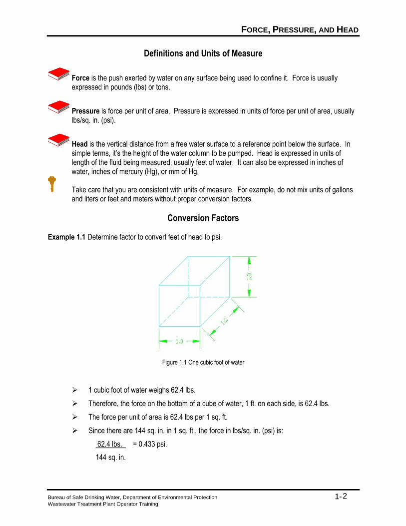
Conversion Factors Example 1.1 Determine factor to convert feet of head to psi.
Figure 1.1 One cubic foot of water
➢ 1 cubic foot of water weighs 62.4 lbs.
➢ Therefore, the force on the bottom of a cube of water, 1 ft. on each side, is 62.4 lbs.
➢ The force per unit of area is 62.4 lbs per 1 sq. ft.
➢ Since there are 144 sq. in. in 1 sq. ft., the force in lbs/sq. in. (psi) is:
62.4 lbs. = 0.433 psi.
144 sq. in.

FORCE, PRESSURE, AND HEAD
Bureau of Safe Drinking Water, Department of Environmental Protection 1- Wastewater Treatment Plant Operator Training
3
Pressure increases with depth. Pressure at any given depth acts the same in ALL directions. It will act on the walls of a vessel as well as the bottom.
FORCE, PRESSURE, AND HEAD
Bureau of Safe Drinking Water, Department of Environmental Protection 1- Wastewater Treatment Plant Operator Training
4
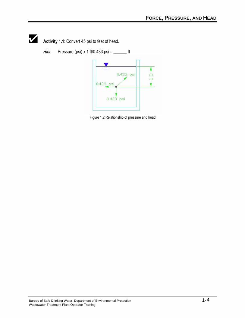
Activity 1.1: Convert 45 psi to feet of head.
Hint: Pressure (psi) x 1 ft/0.433 psi = ______ ft
Figure 1.2 Relationship of pressure and head
FORCE, PRESSURE, AND HEAD
Bureau of Safe Drinking Water, Department of Environmental Protection 1- Wastewater Treatment Plant Operator Training
5
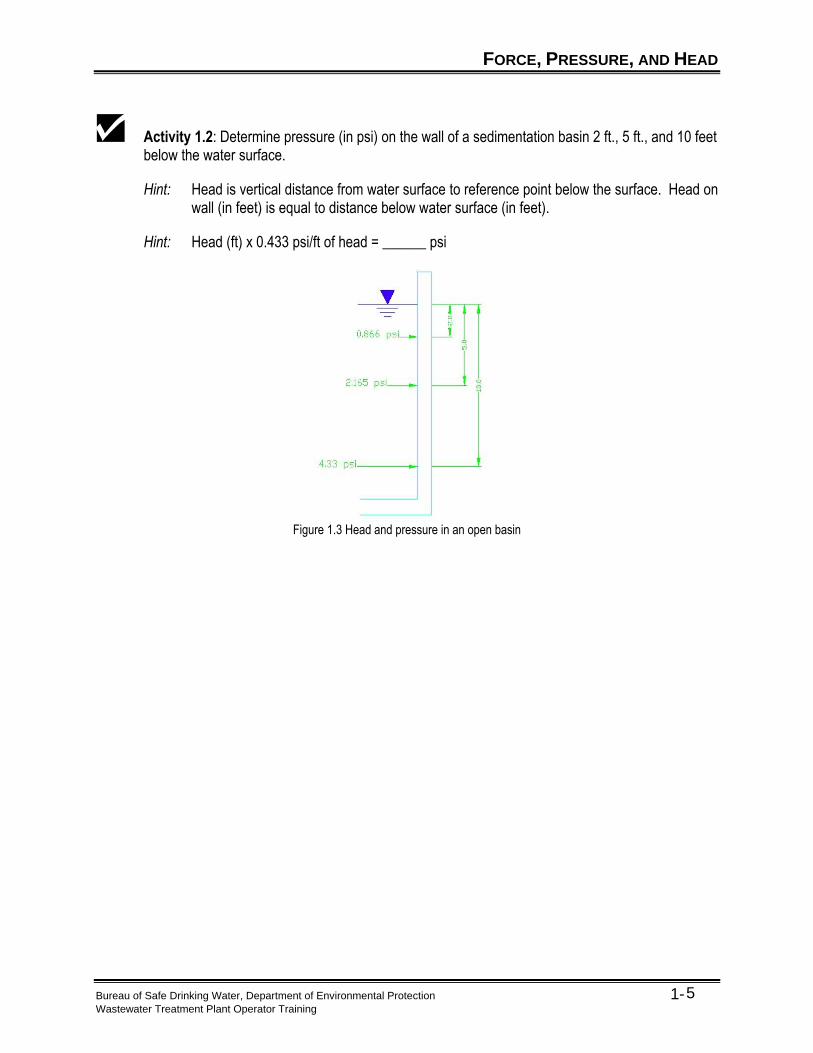
Activity 1.2: Determine pressure (in psi) on the wall of a sedimentation basin 2 ft., 5 ft., and 10 feet below the water surface.
Hint: Head is vertical distance from water surface to reference point below the surface. Head on wall (in feet) is equal to distance below water surface (in feet).
Hint: Head (ft) x 0.433 psi/ft of head = ______ psi
Figure 1.3 Head and pressure in an open basin
FORCE, PRESSURE, AND HEAD
Bureau of Safe Drinking Water, Department of Environmental Protection 1- Wastewater Treatment Plant Operator Training
6
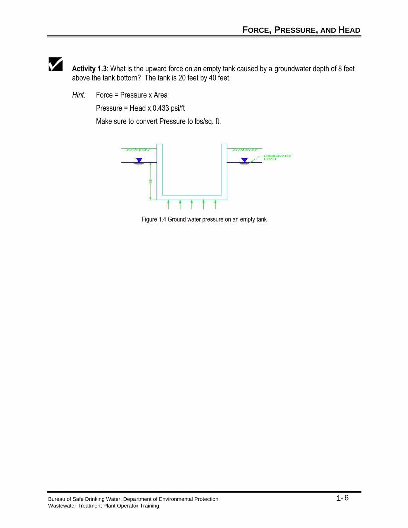
Activity 1.3: What is the upward force on an empty tank caused by a groundwater depth of 8 feet above the tank bottom? The tank is 20 feet by 40 feet.
Hint: Force = Pressure x Area
Pressure = Head x 0.433 psi/ft
Make sure to convert Pressure to lbs/sq. ft.
Figure 1.4 Ground water pressure on an empty tank
VELOCITY AND FLOW RATE
Bureau of Safe Drinking Water, Department of Environmental Protection 1- Wastewater Treatment Plant Operator Training
7
Velocity
Velocity is the speed at which a particle of a substance is moving. It is expressed as a distance traveled over a period of time, for instance miles per hour (mph) or feet per second (fps).
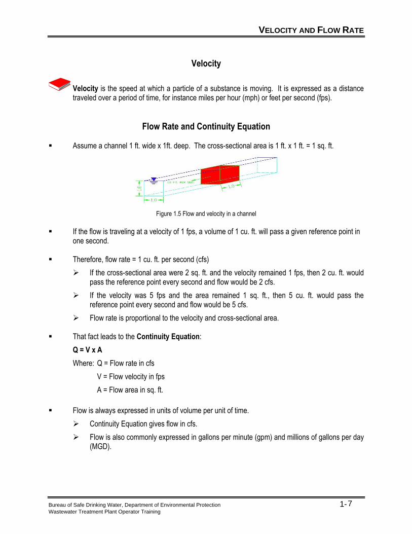
Flow Rate and Continuity Equation ▪ Assume a channel 1 ft. wide x 1ft. deep. The cross-sectional area is 1 ft. x 1 ft. = 1 sq. ft.
Figure 1.5 Flow and velocity in a channel
▪ If the flow is traveling at a velocity of 1 fps, a volume of 1 cu. ft. will pass a given reference point in
one second.
▪ Therefore, flow rate = 1 cu. ft. per second (cfs)
➢ If the cross-sectional area were 2 sq. ft. and the velocity remained 1 fps, then 2 cu. ft. would pass the reference point every second and flow would be 2 cfs.
➢ If the velocity was 5 fps and the area remained 1 sq. ft., then 5 cu. ft. would pass the reference point every second and flow would be 5 cfs.
➢ Flow rate is proportional to the velocity and cross-sectional area.
▪ That fact leads to the Continuity Equation:
Q = V x A
Where: Q = Flow rate in cfs
V = Flow velocity in fps
A = Flow area in sq. ft.
▪ Flow is always expressed in units of volume per unit of time.
➢ Continuity Equation gives flow in cfs.
➢ Flow is also commonly expressed in gallons per minute (gpm) and millions of gallons per day (MGD).
VELOCITY AND FLOW RATE
Bureau of Safe Drinking Water, Department of Environmental Protection 1- Wastewater Treatment Plant Operator Training
8
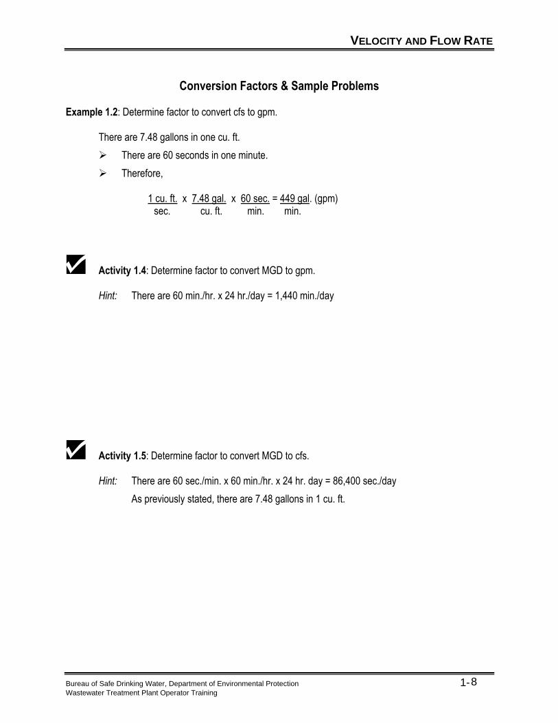
Conversion Factors & Sample Problems Example 1.2: Determine factor to convert cfs to gpm. There are 7.48 gallons in one cu. ft.
➢ There are 60 seconds in one minute.
➢ Therefore, 1 cu. ft. x 7.48 gal. x 60 sec. = 449 gal. (gpm) sec. cu. ft. min. min.
Activity 1.4: Determine factor to convert MGD to gpm.
Hint: There are 60 min./hr. x 24 hr./day = 1,440 min./day
Activity 1.5: Determine factor to convert MGD to cfs.
Hint: There are 60 sec./min. x 60 min./hr. x 24 hr. day = 86,400 sec./day
As previously stated, there are 7.48 gallons in 1 cu. ft.
VELOCITY AND FLOW RATE
Bureau of Safe Drinking Water, Department of Environmental Protection 1- Wastewater Treatment Plant Operator Training
9
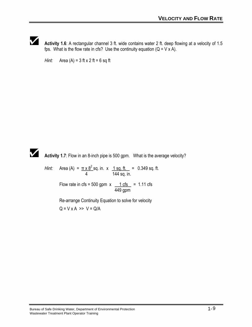
Activity 1.6: A rectangular channel 3 ft. wide contains water 2 ft. deep flowing at a velocity of 1.5 fps. What is the flow rate in cfs? Use the continuity equation (Q = V x A).
Hint: Area (A) = 3 ft x 2 ft = 6 sq ft
Activity 1.7: Flow in an 8-inch pipe is 500 gpm. What is the average velocity?
Hint: Area (A) = π x 82 sq. in. x 1 sq. ft. = 0.349 sq. ft.
4 144 sq. in.
Flow rate in cfs = 500 gpm x 1 cfs = 1.11 cfs 449 gpm
Re-arrange Continuity Equation to solve for velocity
Q = V x A >> V = Q/A
KEY POINTS
Bureau of Safe Drinking Water, Department of Environmental Protection 1- Wastewater Treatment Plant Operator Training
10
Key Points for Unit 1 – Basic Hydraulics
• Pressure is force per unit of area. It is usually measured in lbs/sq. in. and often abbreviated as psi.
• Head is the vertical distance from a free water surface to a reference point below the surface. It is often expressed as feet of water.
• Take care that you are consistent with units of measure. For example, do not mix units of gallons and liters or feet and meters without proper conversion factors.
• Pressure increases with depth.
• Flow is typically expressed in gallons per minute (gpm) or millions of gallons per day (MGD).

KEY POINTS
Bureau of Safe Drinking Water, Department of Environmental Protection 1- Wastewater Treatment Plant Operator Training
11
(This page was intentionally left blank.)
Bureau of Safe Drinking Water, Department of Environmental Protection 2- Wastewater Treatment Plant Operator Training
1
Unit 2 – Open Channel (Gravity) Flow
Learning Objectives
• Define open channel steady state flow. • Name the two sources of energy loss. • Describe the two methods of measuring open channel flow rate.
DEFINITIONS
Bureau of Safe Drinking Water, Department of Environmental Protection 2- Wastewater Treatment Plant Operator Training
2
Open Channel (Gravity) Flow
Open channel (gravity) flow is flow in a channel or conduit where water is contained on sides and bottom but has a free water surface (open to atmosphere) on top. The force of gravity provides the energy necessary to cause the water to flow.
To accurately measure the flow in an open channel sewer or pipe you will need the following:
• The channel or pipe diameter
• The depth of the wastewater
• The velocity of the wastewater
Steady State Flow ▪ A type of open channel flow most commonly encountered in wastewater systems. ▪ In steady state flow, the shape of the channel, depth of flow, and flow velocity are constant from
the upstream end of the channel to the downstream end of the channel. ▪ The slope of the free water surface in the channel matches the slope of the channel bottom.
ENERGY LOSSES
Bureau of Safe Drinking Water, Department of Environmental Protection 2- Wastewater Treatment Plant Operator Training
3
Basic Principles of Energy Losses
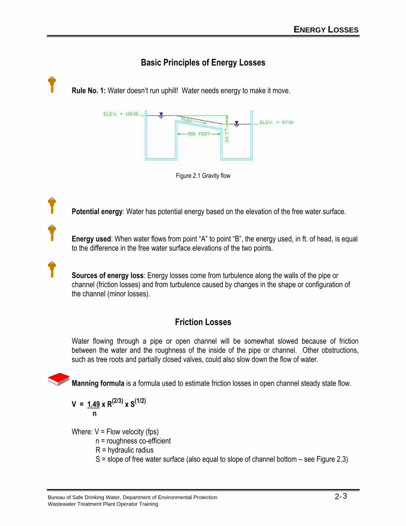
Rule No. 1: Water doesn’t run uphill! Water needs energy to make it move.
Figure 2.1 Gravity flow
Potential energy: Water has potential energy based on the elevation of the free water surface.
Energy used: When water flows from point “A” to point “B”, the energy used, in ft. of head, is equal to the difference in the free water surface elevations of the two points.
Sources of energy loss: Energy losses come from turbulence along the walls of the pipe or channel (friction losses) and from turbulence caused by changes in the shape or configuration of the channel (minor losses).
Friction Losses Water flowing through a pipe or open channel will be somewhat slowed because of friction
between the water and the roughness of the inside of the pipe or channel. Other obstructions, such as tree roots and partially closed valves, could also slow down the flow of water.
Manning formula is a formula used to estimate friction losses in open channel steady state flow.
V = 1.49 x R(2/3)
x S(1/2)
n
Where: V = Flow velocity (fps) n = roughness co-efficient R = hydraulic radius S = slope of free water surface (also equal to slope of channel bottom – see Figure 2.3)
ENERGY LOSSES
Bureau of Safe Drinking Water, Department of Environmental Protection 2- Wastewater Treatment Plant Operator Training
4
Roughness co-efficient is based on the channel material. It can range from 0.010 for very smooth channel surfaces to 0.35 for very rough stone or earth channels. Use 0.014 for most pipe materials.
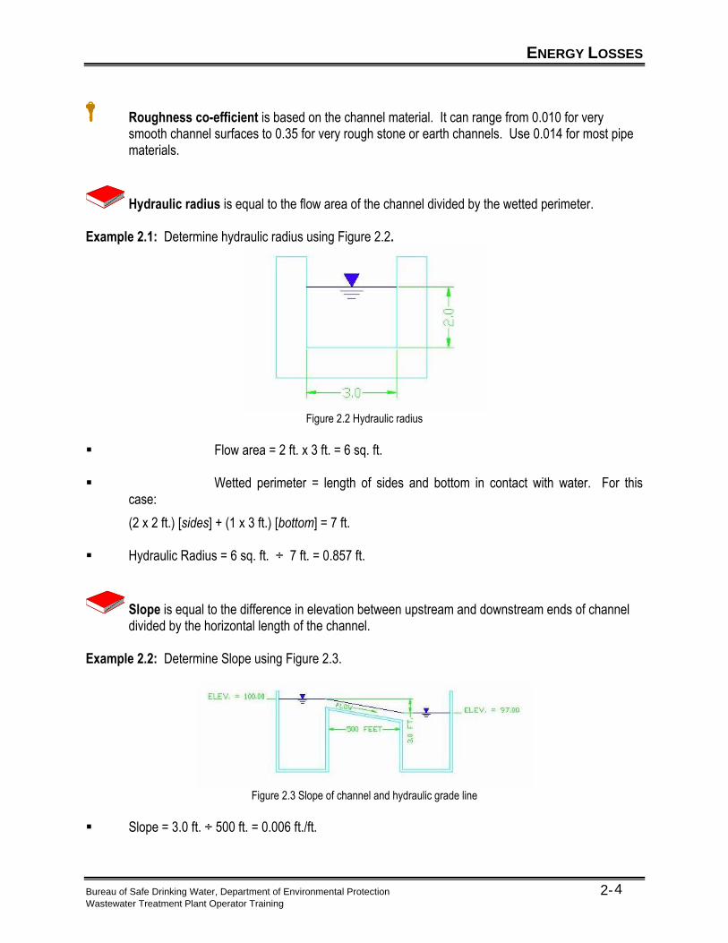
Hydraulic radius is equal to the flow area of the channel divided by the wetted perimeter. Example 2.1: Determine hydraulic radius using Figure 2.2.
Figure 2.2 Hydraulic radius
▪ Flow area = 2 ft. x 3 ft. = 6 sq. ft. ▪ Wetted perimeter = length of sides and bottom in contact with water. For this
case:
(2 x 2 ft.) [sides] + (1 x 3 ft.) [bottom] = 7 ft. ▪ Hydraulic Radius = 6 sq. ft. ÷ 7 ft. = 0.857 ft.
Slope is equal to the difference in elevation between upstream and downstream ends of channel divided by the horizontal length of the channel.
Example 2.2: Determine Slope using Figure 2.3.
Figure 2.3 Slope of channel and hydraulic grade line
▪ Slope = 3.0 ft. ÷ 500 ft. = 0.006 ft./ft.

ENERGY LOSSES
Bureau of Safe Drinking Water, Department of Environmental Protection 2- Wastewater Treatment Plant Operator Training
5
Optional Activity 2.1: What is the flow rate in the channel described in Figure 2.2 Hydraulic radius, and figure 2.3 Slope of channel and hydraulic grade line? Use both the Manning Equation and the Continuity Equation.
ENERGY LOSSES
Bureau of Safe Drinking Water, Department of Environmental Protection 2- Wastewater Treatment Plant Operator Training
6
Estimating Pipe Capacity As an operator, you will not be designing an entire system, however, if you are asked to add an extension to an existing line or replace part of an old line, the following material may be of interest to you. You will need to calculate the area of a circular pipe for this section. The area of a circle is: Area of Circle = (0.785) x (Diameter2) or π x (Radius2)
Where: A (area) = Cross sectional area of pipe in sq. ft. π (pi) = A constant approximately equal to 3.14 D (diameter) = Pipe diameter in ft.
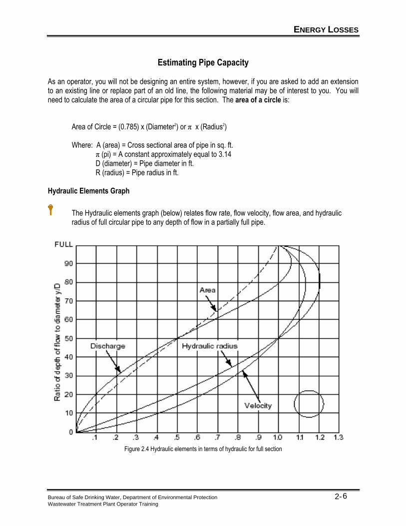
R (radius) = Pipe radius in ft. Hydraulic Elements Graph
The Hydraulic elements graph (below) relates flow rate, flow velocity, flow area, and hydraulic radius of full circular pipe to any depth of flow in a partially full pipe.
Figure 2.4 Hydraulic elements in terms of hydraulic for full section
ENERGY LOSSES
Bureau of Safe Drinking Water, Department of Environmental Protection 2- Wastewater Treatment Plant Operator Training
7
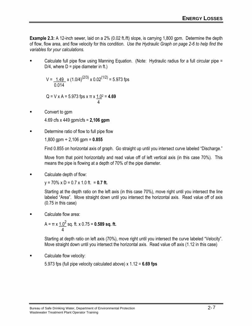
Example 2.3: A 12-inch sewer, laid on a 2% (0.02 ft./ft) slope, is carrying 1,800 gpm. Determine the depth of flow, flow area, and flow velocity for this condition. Use the Hydraulic Graph on page 2-6 to help find the variables for your calculations. ▪ Calculate full pipe flow using Manning Equation. (Note: Hydraulic radius for a full circular pipe =
D/4, where D = pipe diameter in ft.)
▪ Convert to gpm
4.69 cfs x 449 gpm/cfs = 2,106 gpm ▪ Determine ratio of flow to full pipe flow
1,800 gpm ÷ 2,106 gpm = 0.855
Find 0.855 on horizontal axis of graph. Go straight up until you intersect curve labeled “Discharge.”
Move from that point horizontally and read value off of left vertical axis (in this case 70%). This means the pipe is flowing at a depth of 70% of the pipe diameter.
▪ Calculate depth of flow:
y = 70% x D = 0.7 x 1.0 ft. = 0.7 ft.
Starting at the depth ratio on the left axis (in this case 70%), move right until you intersect the line labeled “Area”. Move straight down until you intersect the horizontal axis. Read value off of axis (0.75 in this case)
▪ Calculate flow area:
A = π x 1.02 sq. ft. x 0.75 = 0.589 sq. ft.
4
Starting at depth ratio on left axis (70%), move right until you intersect the curve labeled “Velocity”. Move straight down until you intersect the horizontal axis. Read value off axis (1.12 in this case)
▪ Calculate flow velocity:
5.973 fps (full pipe velocity calculated above) x 1.12 = 6.69 fps
V = 1.49 x (1.0/4)(2/3)
x 0.02(1/2)
= 5.973 fps 0.014 Q = V x A = 5.973 fps x π x 1.02 = 4.69 4
ENERGY LOSSES
Bureau of Safe Drinking Water, Department of Environmental Protection 2- Wastewater Treatment Plant Operator Training
8
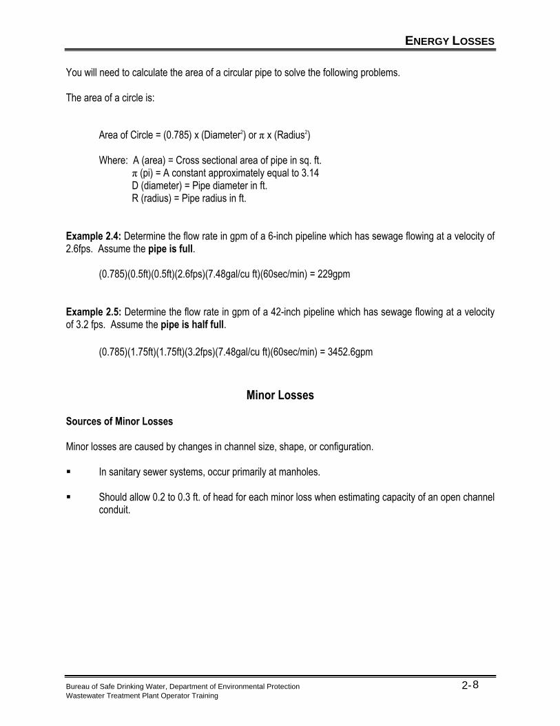
You will need to calculate the area of a circular pipe to solve the following problems. The area of a circle is: Area of Circle = (0.785) x (Diameter2) or π x (Radius2)
Where: A (area) = Cross sectional area of pipe in sq. ft. π (pi) = A constant approximately equal to 3.14 D (diameter) = Pipe diameter in ft.
R (radius) = Pipe radius in ft. Example 2.4: Determine the flow rate in gpm of a 6-inch pipeline which has sewage flowing at a velocity of 2.6fps. Assume the pipe is full.
(0.785)(0.5ft)(0.5ft)(2.6fps)(7.48gal/cu ft)(60sec/min) = 229gpm Example 2.5: Determine the flow rate in gpm of a 42-inch pipeline which has sewage flowing at a velocity of 3.2 fps. Assume the pipe is half full.
(0.785)(1.75ft)(1.75ft)(3.2fps)(7.48gal/cu ft)(60sec/min) = 3452.6gpm
Minor Losses Sources of Minor Losses Minor losses are caused by changes in channel size, shape, or configuration. ▪ In sanitary sewer systems, occur primarily at manholes. ▪ Should allow 0.2 to 0.3 ft. of head for each minor loss when estimating capacity of an open channel
conduit.
OPEN CHANNEL FLOW MEASUREMENT
Bureau of Safe Drinking Water, Department of Environmental Protection 2- Wastewater Treatment Plant Operator Training
9
Flow Measurement
Flumes and weirs are two common methods of measuring flow in open channels.
Parshall Flume
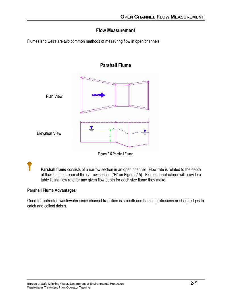
Figure 2.5 Parshall Flume
Parshall flume consists of a narrow section in an open channel. Flow rate is related to the depth of flow just upstream of the narrow section (“H” on Figure 2.5). Flume manufacturer will provide a table listing flow rate for any given flow depth for each size flume they make.
Parshall Flume Advantages Good for untreated wastewater since channel transition is smooth and has no protrusions or sharp edges to catch and collect debris.
Plan View
Elevation View
OPEN CHANNEL FLOW MEASUREMENT
Bureau of Safe Drinking Water, Department of Environmental Protection 2- Wastewater Treatment Plant Operator Training
10
Weir
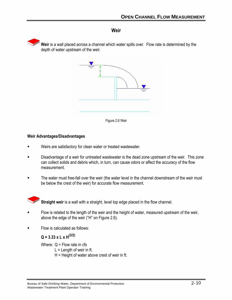
Weir is a wall placed across a channel which water spills over. Flow rate is determined by the depth of water upstream of the weir.
Figure 2.6 Weir
Weir Advantages/Disadvantages ▪ Weirs are satisfactory for clean water or treated wastewater. ▪ Disadvantage of a weir for untreated wastewater is the dead zone upstream of the weir. This zone
can collect solids and debris which, in turn, can cause odors or affect the accuracy of the flow measurement.
▪ The water must free-fall over the weir (the water level in the channel downstream of the weir must
be below the crest of the weir) for accurate flow measurement.
Straight weir is a wall with a straight, level top edge placed in the flow channel. ▪ Flow is related to the length of the weir and the height of water, measured upstream of the weir,
above the edge of the weir (“H” on Figure 2.6). ▪ Flow is calculated as follows:
Q = 3.33 x L x H(3/2)
Where: Q = Flow rate in cfs L = Length of weir in ft. H = Height of water above crest of weir in ft.
OPEN CHANNEL FLOW MEASUREMENT
Bureau of Safe Drinking Water, Department of Environmental Protection 2- Wastewater Treatment Plant Operator Training
11
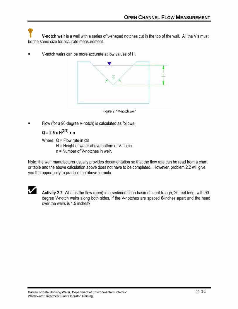
V-notch weir is a wall with a series of v-shaped notches cut in the top of the wall. All the V’s must be the same size for accurate measurement.
▪ V-notch weirs can be more accurate at low values of H.
Figure 2.7 V-notch weir
▪ Flow (for a 90-degree V-notch) is calculated as follows:
Q = 2.5 x H(3/2)
x n
Where: Q = Flow rate in cfs H = Height of water above bottom of V-notch n = Number of V-notches in weir. Note: the weir manufacturer usually provides documentation so that the flow rate can be read from a chart or table and the above calculation above does not have to be completed. However, problem 2.2 will give you the opportunity to practice the above formula.
Activity 2.2: What is the flow (gpm) in a sedimentation basin effluent trough, 20 feet long, with 90-degree V-notch weirs along both sides, if the V-notches are spaced 6-inches apart and the head over the weirs is 1.5 inches?
KEY POINTS
Bureau of Safe Drinking Water, Department of Environmental Protection 2- Wastewater Treatment Plant Operator Training
12
Key Points for Unit 2 – Open Channel (Gravity) Flow
• Gravity provides the energy needed to cause water to flow down an open channel.
• In steady state flow, the slope of the free water surface in the channel matches the slope of the channel bottom.
• Energy losses are classified as friction losses and minor losses.
• The roughness coefficient is a measure of how much friction will be created as water flows over the channel surface.
• Hydraulic radius is the flow area of the channel divided by the wetted perimeter.
• Minor losses occur due to changes in channel size, shape, or configuration. Manholes are good examples.
• Flumes and weirs are commonly used to measure flow in open channels.
EXERCISE
Bureau of Safe Drinking Water, Department of Environmental Protection 2- Wastewater Treatment Plant Operator Training
13
Exercise for Unit 2 – Open Channel Gravity Flow
1. The two devices used most often to measure open channel flow rate are ______________ and ______________.
2. In a steady state open channel flow situation which of the following factors stay the same from the
upstream end of the channel to the downstream end of the channel: a. _____ shape of the channel
b. _____ depth of flow c. _____ flow velocity d. _____ all of the above
3. The __________________ formula is used to estimate friction losses in open channel steady state flows.
4. For most commonly used pipe materials the roughness coefficient (n) can be estimated to be:
a. _____ zero
b. _____ 0.010 c. _____ 0.014 d. _____ 0.35
5. Slope is the difference in elevation between upstream and downstream ends of a channel divided by the horizontal length of the channel. Slope is expressed in units of ______________.
6. Each occurrence of minor losses will contribute approximately _________ to ________ feet of
head losses in open channel flow.
7. Weirs should not be used with:
a. _____ treated wastewater b. _____ clean spring water c. _____ untreated waste water d. _____ all of the above

EXERCISE
Bureau of Safe Drinking Water, Department of Environmental Protection 2- Wastewater Treatment Plant Operator Training
14
(This page was intentionally left blank.)
Bureau of Safe Drinking Water, Department of Environmental Protection 3- Wastewater Treatment Plant Operator Training
1
Unit 3 – Pressure Flow in Force Mains
Learning Objectives
▪ Define hydraulic grade line (HGL). ▪ Describe how static head and high points/siphons affect flow rate. ▪ Describe a system head curve. ▪ Describe how the Venturi Meter and Magnetic Flow Meter measures force main flow.
DEFINITION
Bureau of Safe Drinking Water, Department of Environmental Protection 3- Wastewater Treatment Plant Operator Training
2
Pressure Flow in Force Mains
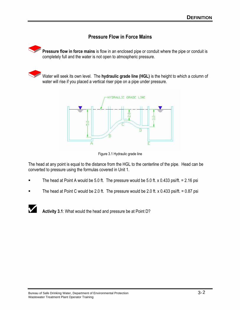
Pressure flow in force mains is flow in an enclosed pipe or conduit where the pipe or conduit is completely full and the water is not open to atmospheric pressure.
Water will seek its own level. The hydraulic grade line (HGL) is the height to which a column of water will rise if you placed a vertical riser pipe on a pipe under pressure.
Figure 3.1 Hydraulic grade line
The head at any point is equal to the distance from the HGL to the centerline of the pipe. Head can be converted to pressure using the formulas covered in Unit 1.
▪ The head at Point A would be 5.0 ft. The pressure would be 5.0 ft. x 0.433 psi/ft. = 2.16 psi
▪ The head at Point C would be 2.0 ft. The pressure would be 2.0 ft. x 0.433 psi/ft. = 0.87 psi
Activity 3.1: What would the head and pressure be at Point D?
ENERGY LOSSES
Bureau of Safe Drinking Water, Department of Environmental Protection 3- Wastewater Treatment Plant Operator Training
3
Basic Principles of Energy Losses
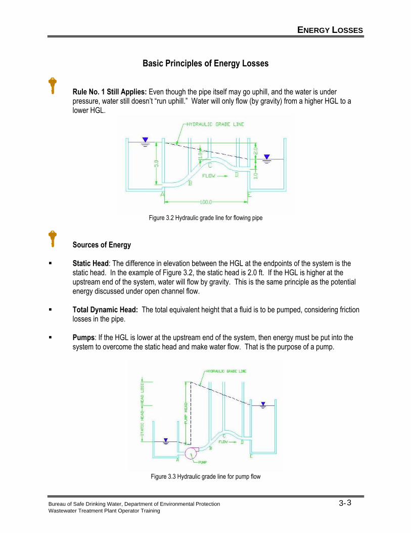
Rule No. 1 Still Applies: Even though the pipe itself may go uphill, and the water is under pressure, water still doesn’t “run uphill.” Water will only flow (by gravity) from a higher HGL to a lower HGL.
Figure 3.2 Hydraulic grade line for flowing pipe
Sources of Energy ▪ Static Head: The difference in elevation between the HGL at the endpoints of the system is the
static head. In the example of Figure 3.2, the static head is 2.0 ft. If the HGL is higher at the upstream end of the system, water will flow by gravity. This is the same principle as the potential energy discussed under open channel flow.
▪ Total Dynamic Head: The total equivalent height that a fluid is to be pumped, considering friction
losses in the pipe. ▪ Pumps: If the HGL is lower at the upstream end of the system, then energy must be put into the
system to overcome the static head and make water flow. That is the purpose of a pump.
Figure 3.3 Hydraulic grade line for pump flow
ENERGY LOSSES
Bureau of Safe Drinking Water, Department of Environmental Protection 3- Wastewater Treatment Plant Operator Training
4
Energy Used: The energy used between two points in the system, in ft. of head, is equal to the difference in elevation of the HGL at those two points. This is the Head Loss (HL).
Sources of Energy Loss: Energy losses in pressure pipe flow come from the same two sources as in open channel flow:
• Friction Losses - Turbulence along the walls of the pipes. Friction losses are high for old pipes in very poor condition (extensive build-up on the inside of the pipe) to low for new, very smooth pipe materials, such as PVC or polyethylene.
• Minor Losses - Changes in pipe size, shape or direction. Minor losses are associated with pipe bends, tees, valves, etc.
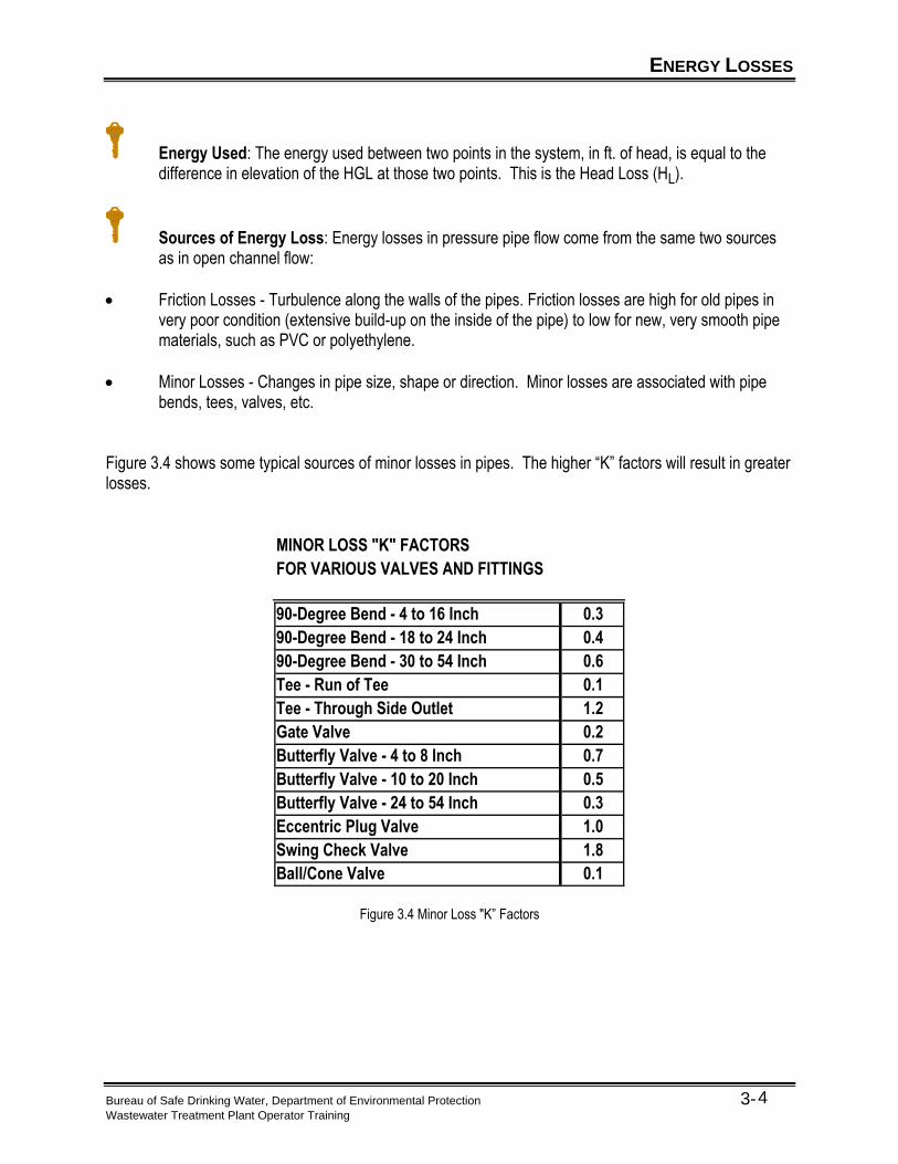
Figure 3.4 shows some typical sources of minor losses in pipes. The higher “K” factors will result in greater losses.
MINOR LOSS "K" FACTORS
FOR VARIOUS VALVES AND FITTINGS
90-Degree Bend - 4 to 16 Inch 0.3
90-Degree Bend - 18 to 24 Inch 0.4
90-Degree Bend - 30 to 54 Inch 0.6
Tee - Run of Tee 0.1
Tee - Through Side Outlet 1.2
Gate Valve 0.2
Butterfly Valve - 4 to 8 Inch 0.7
Butterfly Valve - 10 to 20 Inch 0.5
Butterfly Valve - 24 to 54 Inch 0.3
Eccentric Plug Valve 1.0
Swing Check Valve 1.8
Ball/Cone Valve 0.1
Figure 3.4 Minor Loss "K” Factors
OTHER HYDRAULIC CONSIDERATIONS
Bureau of Safe Drinking Water, Department of Environmental Protection 3- Wastewater Treatment Plant Operator Training
5
Static Head
Recall that static head is the difference in elevation of the HGL’s at the ends of a flow system. If the HGL is lower at the downstream end, water will flow by gravity. If the HGL is higher at the downstream end, a pump must be used to add energy to the system to make the water flow.
High Points/Siphons
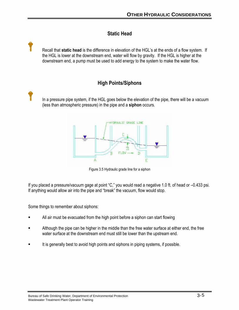
In a pressure pipe system, if the HGL goes below the elevation of the pipe, there will be a vacuum (less than atmospheric pressure) in the pipe and a siphon occurs.
Figure 3.5 Hydraulic grade line for a siphon
If you placed a pressure/vacuum gage at point “C,” you would read a negative 1.0 ft. of head or –0.433 psi. If anything would allow air into the pipe and “break” the vacuum, flow would stop. Some things to remember about siphons: ▪ All air must be evacuated from the high point before a siphon can start flowing ▪ Although the pipe can be higher in the middle than the free water surface at either end, the free
water surface at the downstream end must still be lower than the upstream end. ▪ It is generally best to avoid high points and siphons in piping systems, if possible.
OTHER HYDRAULIC CONSIDERATIONS
Bureau of Safe Drinking Water, Department of Environmental Protection 3- Wastewater Treatment Plant Operator Training
6
System Head Curves
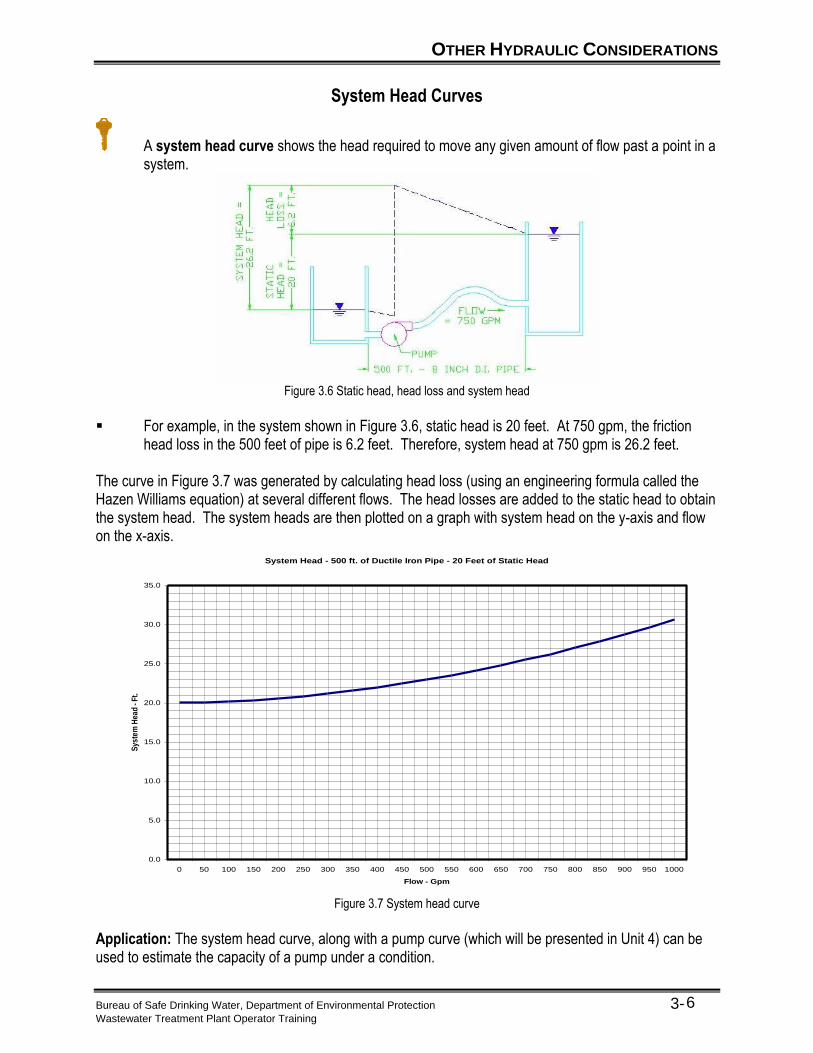
A system head curve shows the head required to move any given amount of flow past a point in a system.
Figure 3.6 Static head, head loss and system head
▪ For example, in the system shown in Figure 3.6, static head is 20 feet. At 750 gpm, the friction
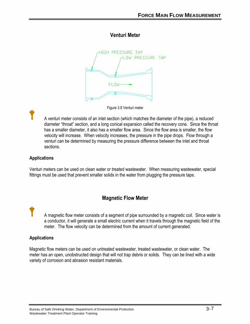
head loss in the 500 feet of pipe is 6.2 feet. Therefore, system head at 750 gpm is 26.2 feet. The curve in Figure 3.7 was generated by calculating head loss (using an engineering formula called the Hazen Williams equation) at several different flows. The head losses are added to the static head to obtain the system head. The system heads are then plotted on a graph with system head on the y-axis and flow on the x-axis.
System Head - 500 ft. of Ductile Iron Pipe - 20 Feet of Static Head
0.0
5.0
10.0
15.0
20.0
25.0
30.0
35.0
0 50 100 150 200 250 300 350 400 450 500 550 600 650 700 750 800 850 900 950 1000
Flow - Gpm
Sys
tem
Hea
d -
Ft.
Figure 3.7 System head curve
Application: The system head curve, along with a pump curve (which will be presented in Unit 4) can be used to estimate the capacity of a pump under a condition.
FORCE MAIN FLOW MEASUREMENT
Bureau of Safe Drinking Water, Department of Environmental Protection 3- Wastewater Treatment Plant Operator Training
7
Venturi Meter
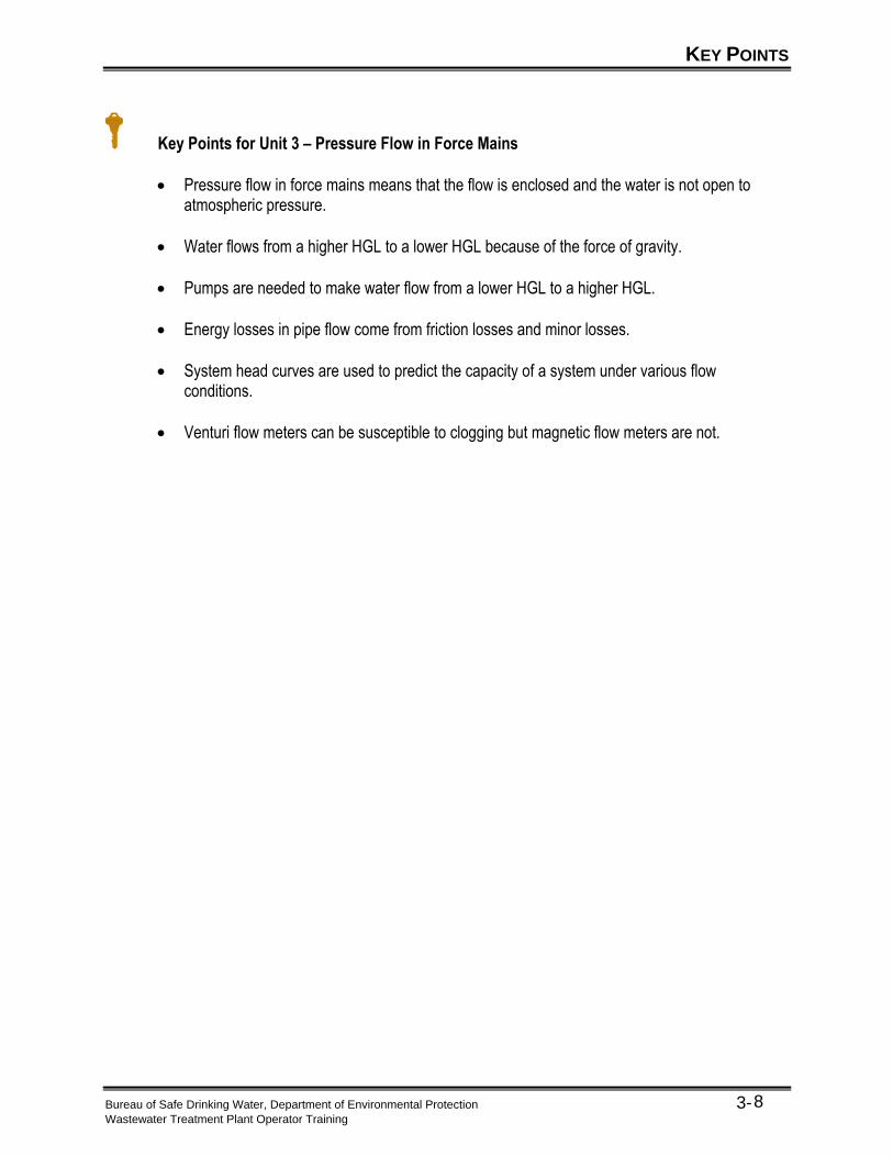
Figure 3.8 Venturi meter
A venturi meter consists of an inlet section (which matches the diameter of the pipe), a reduced diameter “throat” section, and a long conical expansion called the recovery cone. Since the throat has a smaller diameter, it also has a smaller flow area. Since the flow area is smaller, the flow velocity will increase. When velocity increases, the pressure in the pipe drops. Flow through a venturi can be determined by measuring the pressure difference between the inlet and throat sections.
Applications
Venturi meters can be used on clean water or treated wastewater. When measuring wastewater, special fittings must be used that prevent smaller solids in the water from plugging the pressure taps.
Magnetic Flow Meter
A magnetic flow meter consists of a segment of pipe surrounded by a magnetic coil. Since water is a conductor, it will generate a small electric current when it travels through the magnetic field of the meter. The flow velocity can be determined from the amount of current generated.
Applications
Magnetic flow meters can be used on untreated wastewater, treated wastewater, or clean water. The meter has an open, unobstructed design that will not trap debris or solids. They can be lined with a wide variety of corrosion and abrasion resistant materials.
KEY POINTS
Bureau of Safe Drinking Water, Department of Environmental Protection 3- Wastewater Treatment Plant Operator Training
8
Key Points for Unit 3 – Pressure Flow in Force Mains
• Pressure flow in force mains means that the flow is enclosed and the water is not open to atmospheric pressure.
• Water flows from a higher HGL to a lower HGL because of the force of gravity.
• Pumps are needed to make water flow from a lower HGL to a higher HGL.
• Energy losses in pipe flow come from friction losses and minor losses.
• System head curves are used to predict the capacity of a system under various flow conditions.
• Venturi flow meters can be susceptible to clogging but magnetic flow meters are not.
EXERCISE
Bureau of Safe Drinking Water, Department of Environmental Protection 3- Wastewater Treatment Plant Operator Training
9
Exercise for Unit 3 – Pressure Flow in Force Mains
1. Explain the difference between pressure flow in force mains and flow in an open channel.
______________________________________________________________________________
______________________________________________________________________________
______________________________________________________________________________
______________________________________________________________________________
2. HGL is the abbreviation for ___________________ __________________ _________________.
3. A friction loss in water flow is caused by ___________________________________.
4. List three examples of things that will cause minor losses:
a. ________________________
b. ________________________
c. ________________________
5. Which of the following devices would normally be expected to have the greatest minor loss?
a. _____ Butterfly Valve 15 inch
b. _____ 90-degree bend 12 inch
c. _____ Swing Check Valve
d. _____ Gate Valve
6. The difference in elevation of the HGLs at the ends of a flow system is called ___________
______________.
7. Explain why a magnetic flow meter is less susceptible to clogging than a venturi meter.
______________________________________________________________________________
______________________________________________________________________________
______________________________________________________________________________.

EXERCISE
Bureau of Safe Drinking Water, Department of Environmental Protection 3- Wastewater Treatment Plant Operator Training
10
(This page was intentionally left blank.)
Bureau of Safe Drinking Water, Department of Environmental Protection 4-1 Wastewater Treatment Plant Operator Training
Unit 4 – Pump Types and Applications
Learning Objectives
• Define flow, head, horsepower, efficiency, and use them to calculate water horsepower and brake
horsepower. • Describe the basic components of pumps. • Describe the common types of pumps used in wastewater treatment. • Estimate the pumping rate from the pump curve.
PUMP BASICS
Bureau of Safe Drinking Water, Department of Environmental Protection 4-2 Wastewater Treatment Plant Operator Training
Purpose of Pumps in Wastewater Treatment
Pumps supply the energy to “lift” wastewater from lower elevations to higher elevations. They may be used to move wastewater over a hill in a gravity collection system or from one basin to a higher basin in a treatment plant.
Flow, Head, Horsepower, and Efficiency
Flow is the flow rate going through the pump in MGD, gpm, cfs, or other unit of flow.
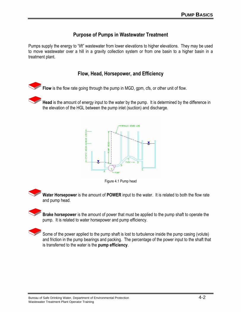
Head is the amount of energy input to the water by the pump. It is determined by the difference in the elevation of the HGL between the pump inlet (suction) and discharge.
Figure 4.1 Pump head
Water Horsepower is the amount of POWER input to the water. It is related to both the flow rate and pump head.
Brake horsepower is the amount of power that must be applied to the pump shaft to operate the pump. It is related to water horsepower and pump efficiency.
Some of the power applied to the pump shaft is lost to turbulence inside the pump casing (volute) and friction in the pump bearings and packing. The percentage of the power input to the shaft that is transferred to the water is the pump efficiency.
PUMP BASICS
Bureau of Safe Drinking Water, Department of Environmental Protection 4-3 Wastewater Treatment Plant Operator Training
Relationships and Calculations ▪ Head and flow to water horsepower:
The most commonly used equation is:
HP = Q x H
3,960
Where: HP = Power applied to water in horsepower. Q = Flow rate in gpm
H = Pump Head in ft. ▪ Brake horsepower to water horsepower
BHP = WHP e
Where: BHP = Brake horsepower (in HP) WHP = Water horsepower (in HP) e = Pump efficiency (expressed as a decimal) ▪ Combining these two formulas relates head and flow directly to brake horsepower. The equation
is:
BHP = Q x H 3,960 x e
Activity 4.1: If a pump is operating at 2,200 gpm and 60 feet of head, what is the water horsepower? If the pump efficiency is 71%, what is the brake horsepower?
PUMP BASICS
Bureau of Safe Drinking Water, Department of Environmental Protection 4-4 Wastewater Treatment Plant Operator Training
Head/Capacity Curves
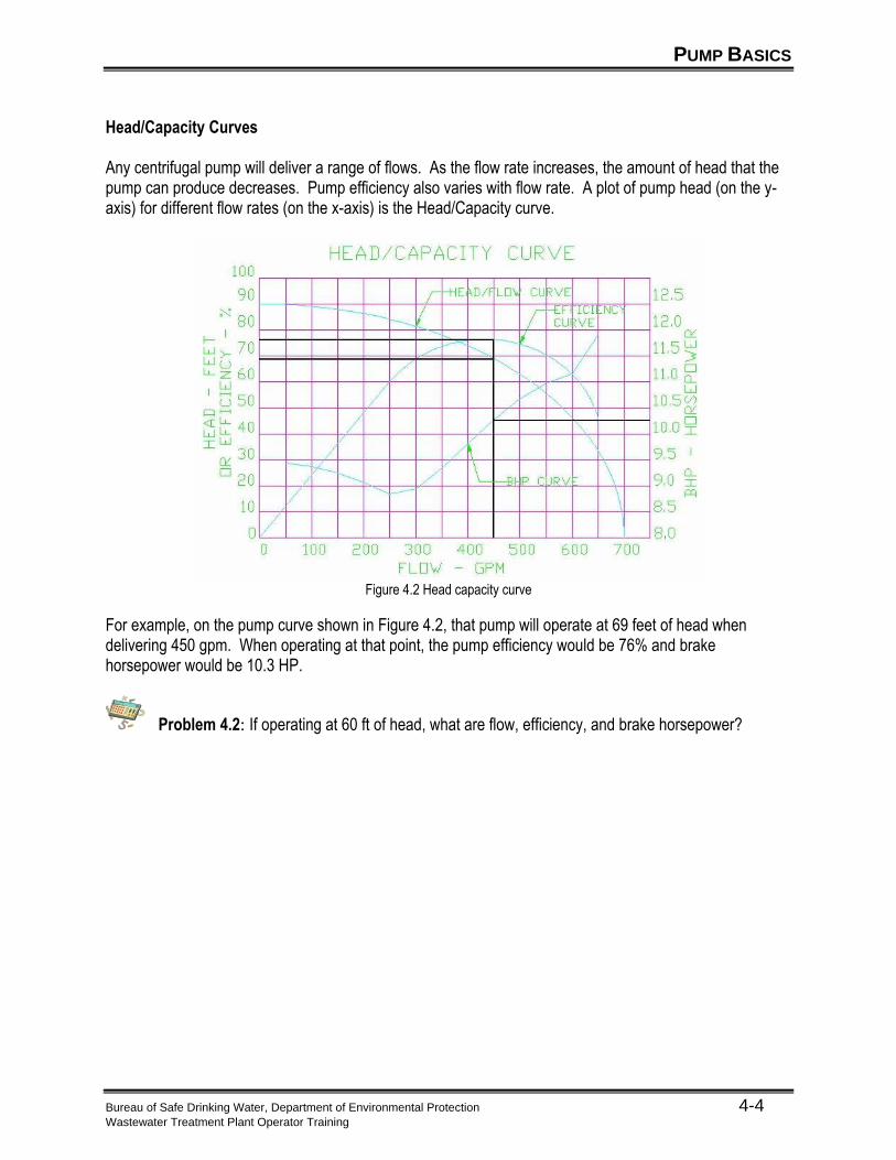
Any centrifugal pump will deliver a range of flows. As the flow rate increases, the amount of head that the pump can produce decreases. Pump efficiency also varies with flow rate. A plot of pump head (on the y-axis) for different flow rates (on the x-axis) is the Head/Capacity curve.
Figure 4.2 Head capacity curve
For example, on the pump curve shown in Figure 4.2, that pump will operate at 69 feet of head when delivering 450 gpm. When operating at that point, the pump efficiency would be 76% and brake horsepower would be 10.3 HP.
Problem 4.2: If operating at 60 ft of head, what are flow, efficiency, and brake horsepower?
CENTRIFUGAL PUMPS
Bureau of Safe Drinking Water, Department of Environmental Protection 4-5 Wastewater Treatment Plant Operator Training
Basic Components
Impeller is a paddle wheel type device at the heart of the pump. Blades on the impeller spin water outward by centrifugal force. As water is spun outward, more water is drawn into the center, or eye, of the impeller. At the time of installation, proper impeller rotation should be checked by performing a bump test.
Shaft supports the impeller. Shaft is protected from corrosion and abrasion by sleeves. Shaft is supported by bearings, which reduce friction on spinning shaft.
Casing (Volute) contains the liquid spinning off the impeller. It has fittings to connect piping to suction side and discharge side of pump.
Suction piping carries water to the eye of the impeller on the suction side of the pump and discharge piping carries water away from the high-pressure side of the volute. The piping connected to a pump should always be independently supported. It should not impart any force onto the pump casing.
The packing seals the opening where the shaft passes through the pump casing. The packing is lubricated by water. The water can come from the pump casing, if the water being pumped is relatively clean. The water must come from a separate source if the water being pumped is carrying a large amount of grit or solids.
Motor provides the power to spin the impeller and pump water. It is connected to the pump shaft by a coupling. The motor shaft and pump shaft must be carefully aligned to prevent excessive loading and wear on the pump bearings and motor bearings. If the impeller is spinning in the wrong direction on a three-phase motor, you will need to reverse the connection on two of the motor leads to correct.
Types and Application Split Case ▪ Suction and discharge are on opposite sides of the pump. ▪ The impeller and pump shaft are mounted perpendicular to the flow. The shaft is supported by
bearings at both ends. The bearings are mounted in the pump casing. ▪ Flow from the suction inlet divides and goes to both sides of the impeller. ▪ The pump casing is “split” horizontally into a top and bottom section. The top half is lifted off for
maintenance and repairs.
CENTRIFUGAL PUMPS
Bureau of Safe Drinking Water, Department of Environmental Protection 4-6 Wastewater Treatment Plant Operator Training
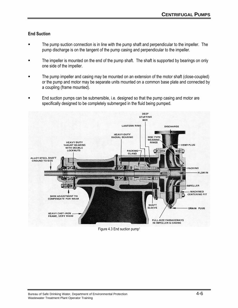
End Suction ▪ The pump suction connection is in line with the pump shaft and perpendicular to the impeller. The
pump discharge is on the tangent of the pump casing and perpendicular to the impeller. ▪ The impeller is mounted on the end of the pump shaft. The shaft is supported by bearings on only
one side of the impeller. ▪ The pump impeller and casing may be mounted on an extension of the motor shaft (close-coupled)
or the pump and motor may be separate units mounted on a common base plate and connected by a coupling (frame mounted).
▪ End suction pumps can be submersible, i.e. designed so that the pump casing and motor are
specifically designed to be completely submerged in the fluid being pumped.
Figure 4.3 End suction pump1
CENTRIFUGAL PUMPS
Bureau of Safe Drinking Water, Department of Environmental Protection 4-7 Wastewater Treatment Plant Operator Training
Vertical Turbine The characteristics of a vertical turbine pump are: ▪ Consist of a pump bowl (casing, impeller and pump shaft) submerged in the water, connected to a
discharge head above the water by a column pipe. The motor is mounted on the discharge head. The pump packing is located in the discharge head. The pump is connected to the motor by a line shaft located in the center of the column pipe.
▪ The pump suction is located on the bottom of the pump bowl. The pump shaft is vertical (in line
with the suction. ▪ A vertical turbine may have several bowls in series. Each bowl adds more head to the water,
increasing the total head of the pump at any given flow.
CENTRIFUGAL PUMPS
Bureau of Safe Drinking Water, Department of Environmental Protection 4-8 Wastewater Treatment Plant Operator Training
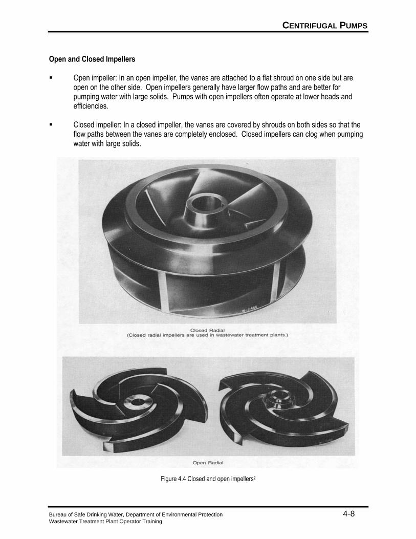
Open and Closed Impellers ▪ Open impeller: In an open impeller, the vanes are attached to a flat shroud on one side but are
open on the other side. Open impellers generally have larger flow paths and are better for pumping water with large solids. Pumps with open impellers often operate at lower heads and efficiencies.
▪ Closed impeller: In a closed impeller, the vanes are covered by shrouds on both sides so that the
flow paths between the vanes are completely enclosed. Closed impellers can clog when pumping water with large solids.
Figure 4.4 Closed and open impellers2
CENTRIFUGAL PUMPS
Bureau of Safe Drinking Water, Department of Environmental Protection 4-9 Wastewater Treatment Plant Operator Training
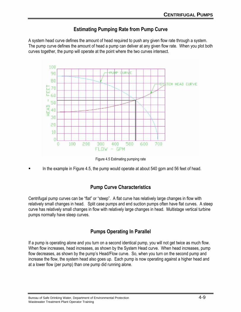
Estimating Pumping Rate from Pump Curve
A system head curve defines the amount of head required to push any given flow rate through a system. The pump curve defines the amount of head a pump can deliver at any given flow rate. When you plot both curves together, the pump will operate at the point where the two curves intersect.
Figure 4.5 Estimating pumping rate
▪ In the example in Figure 4.5, the pump would operate at about 540 gpm and 56 feet of head.
Pump Curve Characteristics Centrifugal pump curves can be “flat” or “steep”. A flat curve has relatively large changes in flow with relatively small changes in head. Split case pumps and end suction pumps often have flat curves. A steep curve has relatively small changes in flow with relatively large changes in head. Multistage vertical turbine pumps normally have steep curves.
Pumps Operating In Parallel
If a pump is operating alone and you turn on a second identical pump, you will not get twice as much flow. When flow increases, head increases, as shown by the System Head curve. When head increases, pump flow decreases, as shown by the pump’s Head/Flow curve. So, when you turn on the second pump and increase the flow, the system head also goes up. Each pump is now operating against a higher head and at a lower flow (per pump) than one pump did running alone.
CENTRIFUGAL PUMPS
Bureau of Safe Drinking Water, Department of Environmental Protection 4-10 Wastewater Treatment Plant Operator Training
Suction Lift and Cavitation
Sometimes a pump must be located above the tank or reservoir it’s pumping from. In this case, the HGL will be below the suction of the pump and there will be a vacuum at the pump suction. This is called suction lift. If the vacuum is too great at the pump suction, the water will flash into vapor forming vapor cavities in the flow. When the pressure is increased by the impeller, these cavities collapse violently and can damage the impeller. The collapse of these cavities is called cavitation. ▪ The pump casing must be full of water before starting the pump. If the pump is located above the
tank or reservoir, the pump casing may drain while the pump is stopped. The casing must be refilled using a priming system before starting.
▪ High vacuum on the suction side of a pump, noisy operation, and premature pump wear are all
signs of potential cavitation and should be investigated and corrected. ▪ Suction lift should be avoided if possible.
POSITIVE DISPLACEMENT PUMPS
Bureau of Safe Drinking Water, Department of Environmental Protection 4-11 Wastewater Treatment Plant Operator Training
General Description ▪ A positive displacement pump is one that moves or “displaces” a fixed volume for each cycle or
rotation of the pump. ▪ The same relationships of head, flow, efficiency and horsepower used for centrifugal pumps also
hold true for positive displacement pumps. Application ▪ Positive displacement pumps are usually used to pump water with a very high solids concentration,
such as waste sludge.
POSITIVE DISPLACEMENT PUMPS
Bureau of Safe Drinking Water, Department of Environmental Protection 4-12 Wastewater Treatment Plant Operator Training
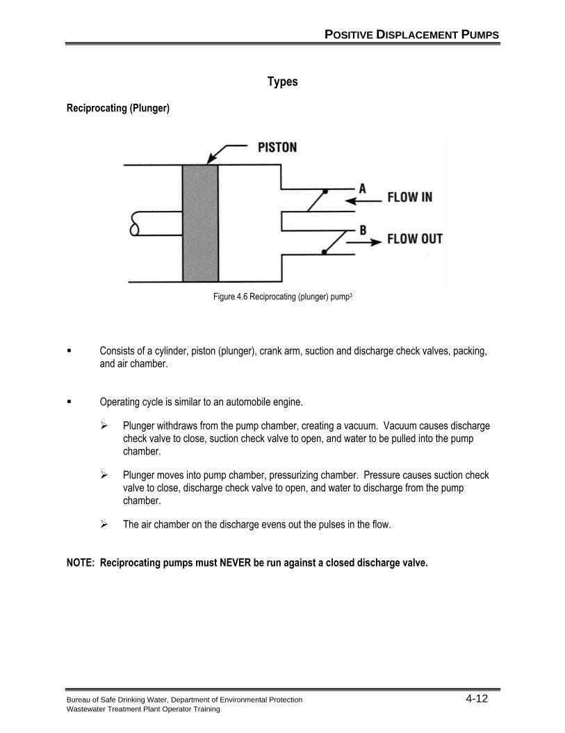
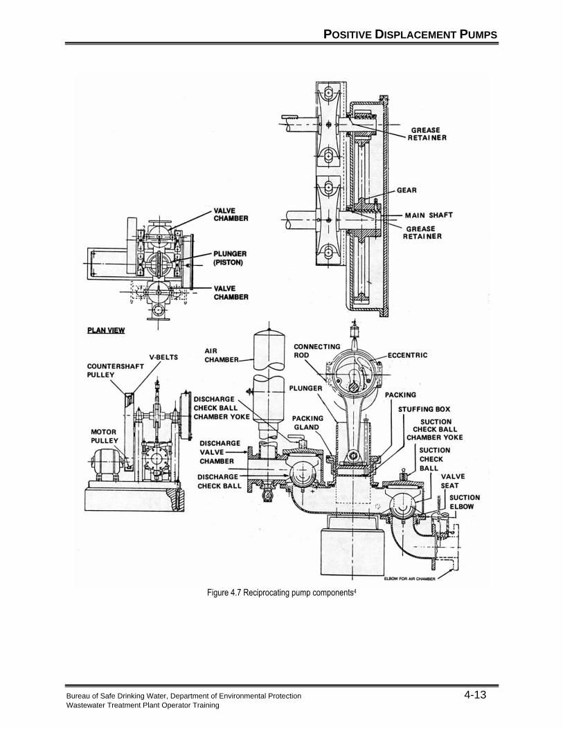
Types Reciprocating (Plunger)
Figure 4.6 Reciprocating (plunger) pump3
▪ Consists of a cylinder, piston (plunger), crank arm, suction and discharge check valves, packing, and air chamber.
▪ Operating cycle is similar to an automobile engine.
➢ Plunger withdraws from the pump chamber, creating a vacuum. Vacuum causes discharge check valve to close, suction check valve to open, and water to be pulled into the pump chamber.
➢ Plunger moves into pump chamber, pressurizing chamber. Pressure causes suction check valve to close, discharge check valve to open, and water to discharge from the pump chamber.
➢ The air chamber on the discharge evens out the pulses in the flow. NOTE: Reciprocating pumps must NEVER be run against a closed discharge valve.
POSITIVE DISPLACEMENT PUMPS
Bureau of Safe Drinking Water, Department of Environmental Protection 4-13 Wastewater Treatment Plant Operator Training
Figure 4.7 Reciprocating pump components4
POSITIVE DISPLACEMENT PUMPS
Bureau of Safe Drinking Water, Department of Environmental Protection 4-14 Wastewater Treatment Plant Operator Training
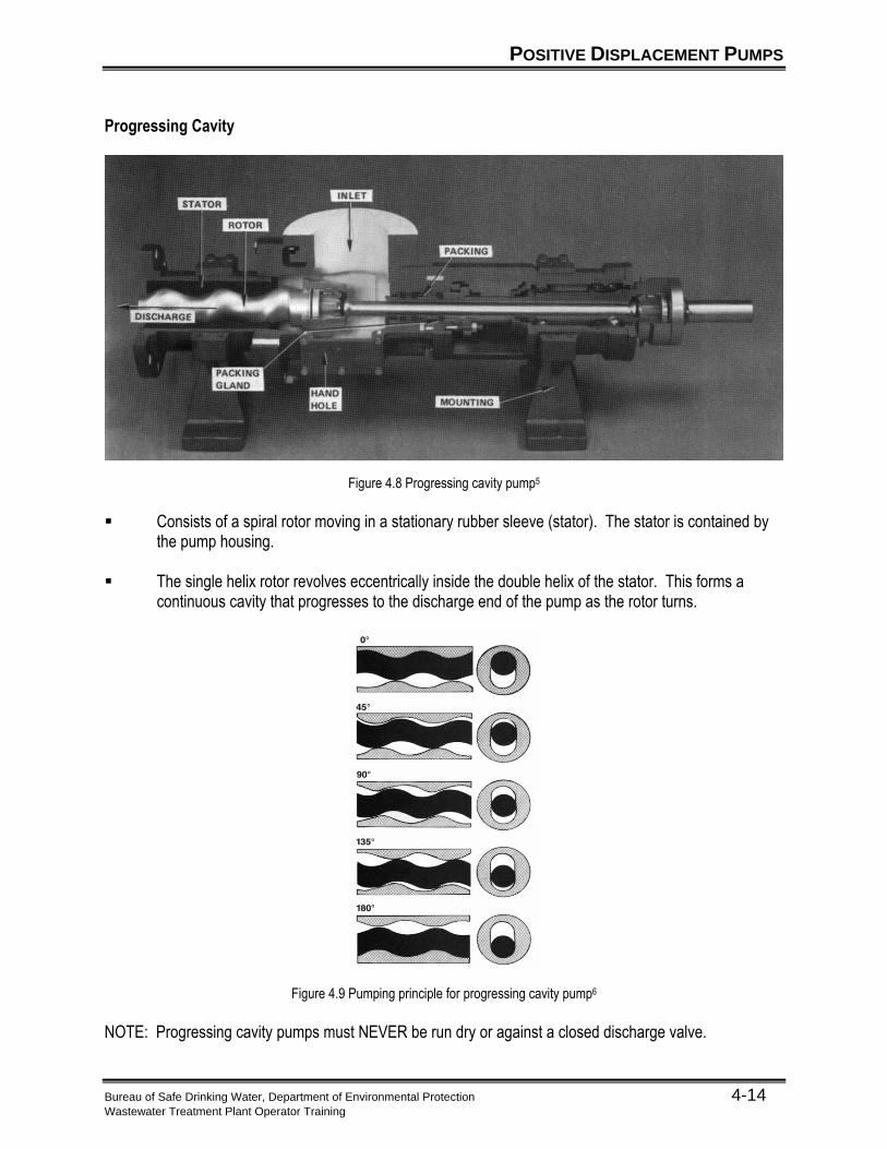
Progressing Cavity
Figure 4.8 Progressing cavity pump5
▪ Consists of a spiral rotor moving in a stationary rubber sleeve (stator). The stator is contained by
the pump housing. ▪ The single helix rotor revolves eccentrically inside the double helix of the stator. This forms a
continuous cavity that progresses to the discharge end of the pump as the rotor turns.
Figure 4.9 Pumping principle for progressing cavity pump6
NOTE: Progressing cavity pumps must NEVER be run dry or against a closed discharge valve.
POSITIVE DISPLACEMENT PUMPS
Bureau of Safe Drinking Water, Department of Environmental Protection 4-15 Wastewater Treatment Plant Operator Training
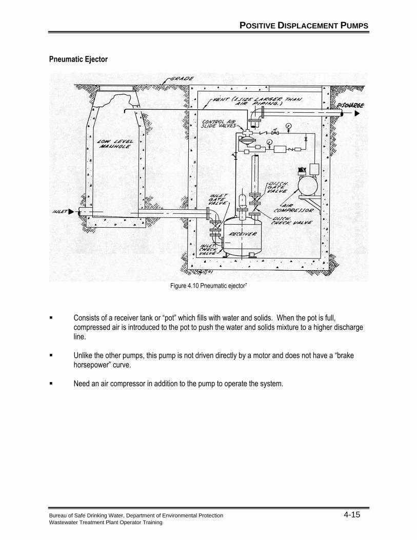
Pneumatic Ejector
Figure 4.10 Pneumatic ejector7
▪ Consists of a receiver tank or “pot” which fills with water and solids. When the pot is full, compressed air is introduced to the pot to push the water and solids mixture to a higher discharge line.
▪ Unlike the other pumps, this pump is not driven directly by a motor and does not have a “brake
horsepower” curve. ▪ Need an air compressor in addition to the pump to operate the system.
POSITIVE DISPLACEMENT PUMPS
Bureau of Safe Drinking Water, Department of Environmental Protection 4-16 Wastewater Treatment Plant Operator Training
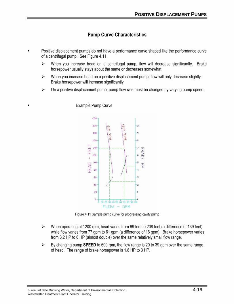
Pump Curve Characteristics
▪ Positive displacement pumps do not have a performance curve shaped like the performance curve of a centrifugal pump. See Figure 4.11.
➢ When you increase head on a centrifugal pump, flow will decrease significantly. Brake horsepower usually stays about the same or decreases somewhat
➢ When you increase head on a positive displacement pump, flow will only decrease slightly. Brake horsepower will increase significantly.
➢ On a positive displacement pump, pump flow rate must be changed by varying pump speed. ▪ Example Pump Curve
Figure 4.11 Sample pump curve for progressing cavity pump
➢ When operating at 1200 rpm, head varies from 69 feet to 208 feet (a difference of 139 feet) while flow varies from 77 gpm to 61 gpm (a difference of 16 gpm). Brake horsepower varies from 3.2 HP to 6 HP (almost double) over the same relatively small flow range.
➢ By changing pump SPEED to 600 rpm, the flow range is 20 to 39 gpm over the same range of head. The range of brake horsepower is 1.8 HP to 3 HP.
POSITIVE DISPLACEMENT PUMPS
Bureau of Safe Drinking Water, Department of Environmental Protection 4-17 Wastewater Treatment Plant Operator Training
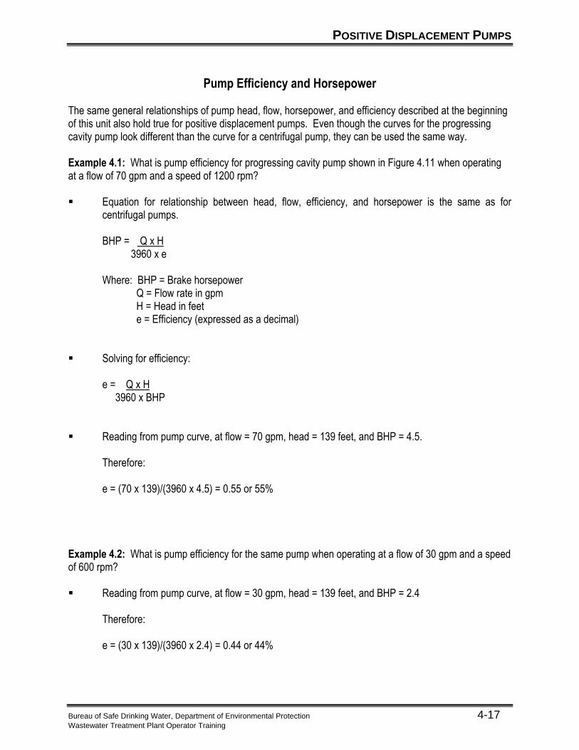
Pump Efficiency and Horsepower
The same general relationships of pump head, flow, horsepower, and efficiency described at the beginning of this unit also hold true for positive displacement pumps. Even though the curves for the progressing cavity pump look different than the curve for a centrifugal pump, they can be used the same way. Example 4.1: What is pump efficiency for progressing cavity pump shown in Figure 4.11 when operating at a flow of 70 gpm and a speed of 1200 rpm? ▪ Equation for relationship between head, flow, efficiency, and horsepower is the same as for
centrifugal pumps. BHP = Q x H 3960 x e Where: BHP = Brake horsepower
Q = Flow rate in gpm H = Head in feet e = Efficiency (expressed as a decimal)
▪ Solving for efficiency:
e = Q x H 3960 x BHP
▪ Reading from pump curve, at flow = 70 gpm, head = 139 feet, and BHP = 4.5.
Therefore: e = (70 x 139)/(3960 x 4.5) = 0.55 or 55%
Example 4.2: What is pump efficiency for the same pump when operating at a flow of 30 gpm and a speed of 600 rpm? ▪ Reading from pump curve, at flow = 30 gpm, head = 139 feet, and BHP = 2.4
Therefore:
e = (30 x 139)/(3960 x 2.4) = 0.44 or 44%
KEY POINTS
Bureau of Safe Drinking Water, Department of Environmental Protection 4-18 Wastewater Treatment Plant Operator Training
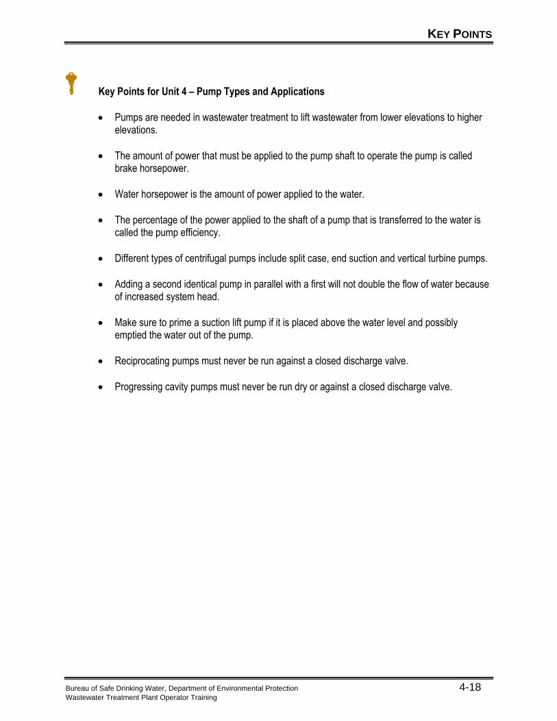
Key Points for Unit 4 – Pump Types and Applications
• Pumps are needed in wastewater treatment to lift wastewater from lower elevations to higher elevations.
• The amount of power that must be applied to the pump shaft to operate the pump is called brake horsepower.
• Water horsepower is the amount of power applied to the water.
• The percentage of the power applied to the shaft of a pump that is transferred to the water is called the pump efficiency.
• Different types of centrifugal pumps include split case, end suction and vertical turbine pumps.
• Adding a second identical pump in parallel with a first will not double the flow of water because of increased system head.
• Make sure to prime a suction lift pump if it is placed above the water level and possibly emptied the water out of the pump.
• Reciprocating pumps must never be run against a closed discharge valve.
• Progressing cavity pumps must never be run dry or against a closed discharge valve.
EXERCISE
Bureau of Safe Drinking Water, Department of Environmental Protection 4-19 Wastewater Treatment Plant Operator Training
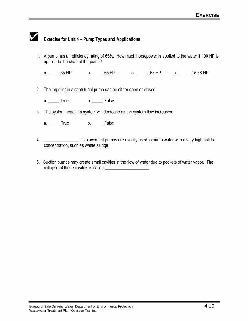
Exercise for Unit 4 – Pump Types and Applications
1. A pump has an efficiency rating of 65%. How much horsepower is applied to the water if 100 HP is applied to the shaft of the pump?
a. _____ 35 HP b. _____ 65 HP c. _____ 165 HP d. _____ 15.38 HP
2. The impeller in a centrifugal pump can be either open or closed. a. _____ True b. _____ False
3. The system head in a system will decrease as the system flow increases.
a. _____ True b. _____ False
4. ________________ displacement pumps are usually used to pump water with a very high solids concentration, such as waste sludge.
5. Suction pumps may create small cavities in the flow of water due to pockets of water vapor. The collapse of these cavities is called ____________________.
REFERENCES
Bureau of Water Supply and Wastewater Management, Department of Environmental Protection 4-20 Wastewater Treatment Plant Operator Training
1 Stan Walton, John Brady, and Roger Peterson, “Chapter 15: Maintenance” in Advance Waste
Treatment, (Sacramento, CA: California State University, Sacramento Foundation, 1998), p. 361.
2 Walton, p. 363.
3 Walton, p. 359.
4 Walton, p.436.
5 Walton, p.369.
6 Walton, p.371.
7 Walton, p.372.